Embed Size (px)
Citation preview

The Moyno progressing cavity pump is a single-screw rotary pump. The pumping action is created by the single helical rotor rolling eccentrically in the double threaded helix of the stator. In its revolution, the rotor forms in conjunction with the stator a series of sealed cavities 180 degrees apart. As the rotor turns the cavities progress from the suction to the discharge. As one cavity diminishes, the opposing cavity is increasing at exactly the same rate. Thus, the sum of the two discharges is a constant volume. The result is a pulsation-less positive displacement flow with no valves. Continental Supply, Co. Continental Supply, Co. 700 B Santa Anita Dr. 12020 Woodruff Ave Woodland, CA 95776 Unit F 800-464-9156 Downey, CA 90241 (530) 669-7966 fax 800-794-3737 (562) 803-1454 fax [email protected] [email protected]

Section: L and J FRAME PUMPS Page: 1 Date: (Revision 11/94)
OPERATION – ASSEMBLY INSTRUCTIONS AND PARTS LIST FOR
“L4” DRIVE END (FRAMES SIZES 1L4, 2L4, 3L4, 3M3, 6M3, 3P2, 6P2, 9P2)
GENERAL The Moyno® Pump is one of the most versatile pumps available. It has been proven in thousands of applications over the past 50 years. It is backed by the experience gained over the years, both in application and manufacturing know-how.
The Moyno progressing cavity pump is a single-screw rotary pump. The pumping action is created by the single helical rotor rolling eccentrically in the double threaded helix of the stator. In its revolution, the rotor forms in conjunction with the stator a series of sealed cavities 180 degrees apart. As the rotor turns the cavities progress from the suction to the discharge. As one cavity diminishes, the opposing cavity is increasing at exactly the same rate. Thus, the sum of the two discharges is a constant volume. The result is a pulsation-less positive displacement flow with no valves.
WARNING 1. Enclose all rotating belts, pulleys, drive shafts, etc., to
comply with acceptable industry safety standards for rotating equipment. Failure to comply could result in personal injury.
2. All pulleys have speed limitations. Refer to pulley manufacturer’s literature for specifications and follow all recommendations, to prevent personal injury.
NAMEPLATE DATA
The Moyno Pump nameplate, located on the bearing housing, carries the serial number, frame size, and type designation. All are extremely important and must be used when ordering spare parts.
Record the nameplate data of your pump in the spaces provided in the heading of Page 3.
Moyno Pumps are identified by Frame and Type. Pump Frame is essentially an indication of size. It consists of a number, a letter, and a number (i.e. 2L4). The first number indicates the number of stages in the pumping elements. The letter indicates the model. The final number indicates the size of the rotor-stator pumping elements. A frame 2L4 pump, therefore, has two stages of size 4 pumping elements.
The “L” in the frame size indicates a standard relationship between the housing, bearings, and drive shaft and the size of the pumping elements. Many variations may be made by adapting smaller element sizes to a larger drive end size. This may be necessary due to the severity of a specific pumping application. In cases where the drive end (housing, bearings, and drive shaft) is one size larger than the element size normally used, the pump is referred to as an “M” frame pump (i.e. 3M3). If the drive end is two sizes larger than the element size, the pump is referred to
as a “P” frame. Thus, a frame 3L4, 3M3, and 3P2 would all use a common drive end.
Type designation is a series of letters which identify the “Materials of Construction” in component groups of parts. The usual type designation will consist of three letters.
The first letter identifies the material of the suction housing casting or the body casting where the bearing housing is a part of the suction housing. C — Cast Iron E — Alloy cb-20 Stainless H — Hastelloy “C” M — Monel S — 316 Stainless Steel W — Cast Steel (Available only on 1L14 body) X — Special to application
The second letter indicates the material used in the drive shaft, pins, connecting rod, rotor, and other minor metallic parts in contact with the material being pumped. D — Alloy Steel E — Alloy cb-20 Stainless G — 416 Stainless Steel H — Hastelloy “C” J — 17-4 PH Stainless Steel M — Monel S — 316 Stainless Steel X — Special to application
The third letter determines the material of the stator. It identifies only the stator material and not that of the tube in which the stator is placed. B — EPDM 300, 70 Durometer C — Nitrile 103, 50 Durometer D — Tool Steel E — Nitrile 110, 70 Durometer F — Viton 500, 75 Durometer G —416 Stainless Steel H — Hastelloy “C” J — 17-4 PH Stainless Steel K — Hypalon 800, 70 Durometer M — Nitrile 100M, 70 Durometer P — Thiokol 70 Durometer Q — Nitrile 100, 700 Durometer R — Natural Rubber 200, 55 Durometer T — Teflon 15% glass U — Urethane 70 Durometer X — Special to application Z — Nitrile 150, 70 Durometer

•
2

* Add third letter of type designation to complete Part No. ** Bearing Kit includes Items A thru G EX: Type CDQ pump – add Q to basic number of stator *** Connecting Rod Kit includes items Q thru V. + See pages 5 – 6 for variations
“L4” DRIVE END PARTS TYPE DESIGNATIONS
Select type column corresponding to type designation at left. Order by part number Refer to frame size to select proper rotor and stator.
REF. NO.
DESCRIPTION
CDQ CDR CDB CDF
Part No.
CDD CDG CDT
Part No.
CSQ CSR CSB CSF
Part No.
CSG CSD CST
Part No.
SSQ SSR SSB SSF
Part No.
SSG SST
Part No. A. Ball Bearing (Radial) A04291 A04291 A04291 A04291 A04291 A04291 B. Ball Bearing (Thrust) A04301 A04301 A04301 A04301 A04301 A04301 C. Bearing Spacer A04331 A04331 A04331 A04331 A04331 A04331 D. Bearing Lock Nut A04581 A04581 A04581 A04581 A04581 A04581 E. Bearing Lock Washer A04591 A04591 A04591 A04591 A04591 A04591 F. Grease Seal (Radial) A04611 A04611 A04611 A04611 A04611 A04611 G. Grease Seal (Thrust) A04621 A04621 A04621 A04621 A04621 A04621
Bearing Kit** K04291 K04291 K04291 K04291 K04291 K04291 H. Bearing Housing A04051 A04051 A04051 A04051 A04051 A04051 I. Bearing Cover Plate A04341 A04341 A04341 A04341 A04341 A04341 J. Pump Support A04371 A04371 A04371 A04371 A04371 A04371 K. Shaft Collar A04491 A04491 A04491 A04491 A04491 A04491 M. Lantern Ring A04571 A04571 A04571 A04571 A04571 A04571 N. Stator Support 1L4, 2L4
3L3, 6M3 A04381 A04382 A04381 A04382 A04381 A04382 3M3, 6P2, 3P2 A04381 A04381 A04381 A04381 A04381 A04381 9P2 A04383 ---------- A04383 ---------- A04383 ----------
O. Support Bushing 3M3 A04711 ---------- A04711 ---------- A04711 ---------- 3P2, 6P2 A03711 A04711 A03711 A04711 A03711 A04711
P. Pin Retainer A04501 A04501 A04501 A04501 A04501 A04501 Q. Retaining Screw Washer A04731 A04731 A04731 A04731 A04731 A04731 R. Connecting Rod Washer A04531 A04531 A04531 A04531 A04531 A04531 S. Connecting Rod B0425D B0425D B0425S B0425S B0425S B0425S T. Rotor Pin B0445D B0445D B0445S B0445S B0445S B0445S U. Shaft Pin B0446D B0446D B0446S B0446S B0446S B0446S V. Drive Pin Retaining Screw B0454D B0454D B0454S B0454S B0454S B0454S
Connecting Rod Kit*** K0425D K0425D K0425S K0425S K0425S K0425S W. Suction Housing B04021 B04022 B04021 B04022 B04026 B04027 X. Reducer 1L4, 2L4, 3L4 B04091 B04092 B04091 B04092 B04096 B04097
6M3 B03092 B04092 B03091 B04092 B03096 B04097 3M3 B03091 B03092 B03091 B03092 B03096 B03097 3P2, 6P2 B02091 B02092 B02091 B02092 B02096 B02097 9P2 B03091 ---------- B03091 ---------- B03096 ----------
Y. Drive Shaft + B04261 B04261 B04266 B04266 B04266 B04266 Z. Packing Gland B0441D B0441D B0441S B0441S B0441S B0441S
AA. Packing + B04421 B04421 B04425 B04425 B04425 B04425 BB. Packing Washer B0465D B0465D B0465S B0465S B0465S B0465S CC. Adapter Bushing 3M3, 9P2 B03512 B04511 B03512 B04511 B04516 B03517
3P2, 6P2 B04512 B03511 B04512 B03512 B04517 B03517 FF. Stator Frame 1L4 C4104* C4104* C4104* C4104* C5104* C5104*
Frame 2L4 C4204* C4204* C4204* C4204* C5204* C5204* Frame 3L4 C4304* C4304* C4304* C4304* C5304* C5304* Frame 3M3 C4303* C4303* C4303* C4303* C5303* C5303* Frame 6M3 C4603* C4603* C4603* C4603* C5603* C5603* Frame 3P2 C4303* C4303* C4302* C4302* C5302* C5302* Frame 6P2 C4602* C4602* C4602* C4602* C5602* C5602* Frame 9P2 C4902* ---------- C4902* ---------- C5902* ----------
GG. Rotor Frame 1L4 + C71041 C71041 C81041 C81041 C81041 C81041 Frame 2L4 + C72041 C72041 C82041 C82041 C82041 C82041 Frame 3L4 + C73041 C73041 C83041 C83041 C83041 C83041 Frame 3M3 + M73031 M73031 M83031 M83031 M83031 M83031 Frame 6M3 + C76031 C76031 C86031 C86031 C86031 C86031 Frame 3P2 + P73021 P73021 P83021 P83021 P83021 P83021 Frame 6P2 + P76021 P76021 P86021 P96021 P86021 P86021 Frame 9P2 + P79021 ---------- P89021 ---------- P89021 ----------
3

A typical type designation such as CDQ would result in
the following: C = Cast Iron Suction Housing D = Hardened Steel Internals including drive shaft,
pins, connecting rod, rotor, and other minor metallic parts in contact with the material being pumped
• Q = Buna N Synthetic Rubber Stator (70 durometer) Also included on the nameplate is the three-character
trim code designation. This only appears on pumps which have semi-standard or special construction. The first letter identifies sealing variations, the second character identifies internal variations, and the third letter identifies rotor variations.
On page 5 of this manual are variations available for modifying pumps to meet specialized pumping conditions. If the trim code of your pump is other than “AAA", contact your nearest Moyno representative for clarification. Do not use any variation unless you have determined that it is compatible with your application. INSTRUCTIONS FOR DISASSEMBLY AND ASSEMBLY
Frames 1L4, 2L4, 3L4, 3M3, 6M3, 3P2, 6P2, 9P2 Disassembly Procedure 1. Disconnect the power source. 2. Close the suction and discharge valves to isolate the
pump from the line. 3. Turn off flush water to packing or rotary seal if used. 4. Remove drain plug in suction housing to drain away any
fluid remaining in pump. 5. Place a support block under suction housing in area of
drain plug. Wooden blocks are sufficient. The purpose is to prevent undue stress on pump support when pump is disassembled.
6. Disconnect piping from stator end of pump. 7. Stator Removal - With pipe wrench or strap wrench
remove discharge reducer (X). Remove cap of stator support and with strap wrench or pipe wrench, unscrew the stator (FF) from the suction housing. Pull Stator off the rotor.
8. Rotor Removal . The rotor (GG) is removed with the connecting rod (S) and rotor pin (T) as a unit. Removal of the unit is accomplished by removing the two drive pin retaining screws (V) located in the shaft collar (K). This step reveals the shaft drive pin (U) which is removed by driving the pin from the drive shaft (Y) with a small punch or drift pin. Slide the shaft collar toward the packing gland (Z) and remove the retaining screw washers (Q) from each side of the drive shaft. The rotor and connecting rod can now be removed by pulling them from the pump. To disassemble, clamp the connecting rod (S) by its mid-section in a vise and, with a drift pin, drive the pin retainer (P) from the head of the rotor. The rotor pin (T) can now be removed from the rotor freeing the connecting rod. Remove the connecting rod washers (R) if present.
9. To remove packing (AA), remove nuts holding packing gland (Z). Slip packing gland from studs, remove packing rings, lantern ring (M), and remaining packing rings. Packing rings can be removed with a standard packing puller. Note: If step 10 is to be performed, it should precede step 9 as packing can then be removed by freeing packing gland and driving packing, lantern ring, and packing washer (BB) from housing using a small rod. Rod should enter where stator screws into suction housing. Place rod on packing washer and tap. Entire set should easily exit from opposite end of
stuffing box. 10. Drive Shaft & Bearing Removal - With rotor removed
it is now possible to remove the drive shaft and bearings as a sub-assembly. Remove the four cap screws holding the bearing cover plate (I) and slip from shaft. Insert a bar or rod into the hollow end of drive shaft (Y) where it enters the suction cavity. By tapping on the rod the entire assembly will be forced from the bearing housing. To disassemble, remove bearing lock nut (D) and bearing lock washer (E). Using an arbor press remove radial bearing (A), bearing spacer (C), and thrust bearing (B). Apply pressure to inner race only. When replacing drive shaft and/or bearings, it is recommended that both grease seals be replaced. Grease seals are pressed into the bearing housing and bearing cover plate.
Assembly Procedure
Moyno pumps are reassembled in the reverse order of disassembly with special notes as outlined below: 1. Always replace all old washers, “O” rings, and packing.
We also recommend replacing grease seals when new bearings are installed.
2. Bearing Shaft Assembly - When installing new bearings, make sure that they are seated against the shoulder on the shaft. Replace bearing lock washer and bearing lock nut. Tighten bearing lock nut securely. Bend tab down onto lock nut to prevent loosening of nut. Make sure that the shaft collar, packing gland, and packing washer are installed on the drive shaft as the hollow end emerges in the bearing housing and approaches the stuffing box area. When replacing the bearing cover plate, tighten all cap screws evenly to prevent damage to the bearing cover plate and thrust grease seal. Do not over-lubricate bearings. (See Maintenance)
3. When installing the connecting rod, make sure that the hole in the rod is aligned with the holes in the drive shaft and shaft collar before inserting the pin. Always use retaining screw washers and make sure that the hollowed end of the retaining screw fits over the end of the shaft pin to ensure a tight fit. Retaining screws must seat on retaining screw washers and not on pin.
4. When replacing packing, insert two rings on the shaft, the lantern ring, and then four more rings. This will allow the lantern ring to line up with the grease fitting on the stuffing box. Make sure you stagger the ends of the packing rings. When installing the new packing, you may find that all but one ring will go on the drive shaft. When the pump has run for a short time and the new packing is compressed, this final ring can be installed.
5. When installing the stator on the rotor, it is best to lubricate the rotor with water (or a lubricant compatible with the rubber in the stator) to allow the stator to slip on easier. (Grease or oil is not compatible with type "R” or “B” stators.) When replacing the stator, always tighten it with the pipe wrench on the end of the stator nearest the suction housing. This will prevent it from binding and damaging the threads. If your stator has a stainless steel sleeve, use a teflon tape or similar material on the threads before replacing -- on all stators with a carbon steel sleeve, use pipe dope.
4

6. CautIon: Dry operation is harmful to the pump. Always fill the pump with fluid to be handled prior to start up. Check any valves in discharge line to determine that no restrictions exist.
MAINTENANCE
The Moyno pump has been designed for a minimum of maintenance, the extent of which is routine lubrication and adjustment of packing and infrequent lubrication of the bearings. The pump is one of the easiest to work on in that the main elements are very accessible and require few tools to disassemble. Packing
The Moyno pump is normally furnished with die formed packing. The packing may be either grease lubricated through a grease fitting in the stuffing box or have plumbing connected to the housing to allow a water flush. (See Water Flush of Packing) Packing gland adjusting nuts should be evenly adjusted so they are little more than finger tight. Over-tightening of the packing gland may result in premature packing failure and possible damage to the shaft and gland. When the packing is new, frequent minor adjustments are recommended for the first few hours of operation in order to compress and seat the packing. Greasing the packing often but with limited quantities of grease is the best practice. This can be done through a grease fitting which leads to a lantern ring in the mid-section of the packing. Do not use a one-piece spiral wrap of packing.
Water Flush of Packing
When the material being pumped is abrasive in nature, it may be advantageous to flush the packing to prevent leakage under packing and excessive shaft wear.
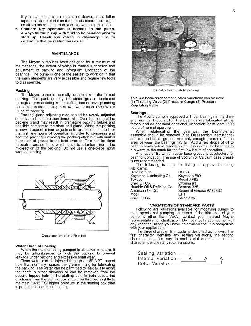
Clean water can be injected through a 1/8” NPT tapped hole that normally houses the grease fitting for lubricating the packing. The water can be permitted to leak axially along the shaft in either direction or can be removed from the second tapped hole in the stuffing box. In both cases, the discharge from the stuffing box should be throttled slightly to maintain 10-15 PSI higher pressure in the stuffing box than is present in the suction housing.
This is a basic arrangement, other variations can be used. (1) Throttling Valve (2) Pressure Guage (3) Pressure Regulating Valve Bearings
The Moyno pump is equipped with ball bearings in the drive end size L2 through L10. The bearings are lubricated at the factory and do not need additional lubrication for at least 1500 hours of normal operation.
When relubricating the bearings, the bearing-shaft assembly should be removed (See Disassembly instructions) and cleaned of old grease. Add only enough grease to fill the area between the bearings 1/3 full. Add a few drops of oil to bearing seals before reassembling. It is normal for bearings to run warm to the touch for the first few hours of operation.
Any type of Ep Lithium soap base grease is satisfactory for bearing lubrication. The use of Sodium or Calcium base grease is not recommended.
The following is a partial listing of approved bearing lubricants: Dow Corning DC 33 Keystone Lubricating Co. Keystone #89 Texaco Regal AFB2 Shell Oil Co. Cyprina #3 Humble Oil & Refining Co. Beacon 325 American Oil Co. Supermil Grease #A72832 Mobil EP1 Shell Oil Co. Alvania #2
VARIATIONS OF STANDARD PARTS
Following are variations available for modifying pumps to meet specialized pumping conditions. If the trim code of your pump is other than “AAA,” contact your nearest Moyno representative for clarification. Do not modify your pump with any variation unless you have determined that it is compatible with your application.
The three-character trim code is designed as follows. The first character identifies any sealing variations, the second character identifies any internal variations, and the third character identifies any rotor variations.
5

The trim code “AAA” represents a pump with standard features. Deviations from standard are to be indicated by changing the appropriate character from the choices listed. When two or more letters are combined, dashes are used to separate the three areas of the trim code for clarity. SEALING VARIATIONS
A — BRAIDED TEFLON & GRAPHITE PACKING, (Black) Standard to all lines except Quick Disassembly pumps. Optional on Quick Disassembly pumps.
C — BRAIDED TEFLON PACKING, (White) Optional
packing on all lines.
D — DOUBLE MECHANICAL SEAL, Optional on all lines. Not offered on #2 “L” frame.
F — BRAIDED TEFLON FOOD GRADE PACKING,
(White) Standard on all Quick Disassembly pumps. Optional on all other lines.
G — 100% GRAPHITE PACKING, (Gray) Optional to all
lines.
S — SINGLE MECHANICAL SEAL, Optional on all lines.
W — WATER FLUSH, Optional on all lines.
X — Special to application. INTERNAL VARIATIONS A — Standard plated shaft B — Non-plated shaft C — Solid drive shaft configuration D — Grit seal, for “L” frame only E — Extension tube with extended auger F — Extended drive shaft (for back stop or large pulley) G — Ceramic coating S — Shaft sleeve X — Special to application ROTOR VARIATIONS A — Standard size with chrome plating B — Non-plated (no plating) C — Standard undersize E — Standard oversize F — Counter clockwise rotation (Centennial line only) G — Ceramic coating X — Special to application
ROTORS identified on parts listing are standard size with hard-chrome plated surface. Other variations of rotor size and finish may be ordered by selecting the standard rotor part number and changing the last digit of the rotor number as follows:
2 = Standard size, non-plated 3 = Undersize, chrome-plated 4 = Undersize, non-plated 5 = Oversize, chrome-plated
Do not change rotor sizes without consulting your local Moyno Sales Office. These variations are used for certain specialized pumping conditions only.
PACKING VARIATIONS listed are common to most type designations. Others may be specified by changing the last digit to the following:
1 = Standard on all type CDQ pumps 3 = Standard on all type CDR & SSR pumps 5 = Standard on all type SSQ pumps 7 = Optional--Solid Braided Teflon 8 = Optional--Teflon impregnated white asbestos
DRIVE SHAFTS shown have hard-chrome plating on the packing wear area. If non-plated drive shafts are required, select the standard part number and change the last digit to next higher number. Example: B04261 to B04262.
L4 STANDARD HARDWARE
ITEM SIZE # REQ. Lock Washer 4 Packing Gland Stud 21/2LX3/8D-16 2 Packing Gland Bolt Nut 2 1/2L X 3/8D-16 2 Nut 1 1/2LX3/8D-16 2 Stator & Pump Support Screws 1 3/4L X 3/80-16 4 Suction Housing Drain Plug 1/2NPT 3 Pipe Plug 1/8NPT 2 Grease Fitting 1/8NPT 1 Hex Key 5/16 1
RECOMMENDED SPARE PARTS
The Moyno pump has been designed and built with all
wearable parts replaceable. A recommended inventory of spare parts is dependent upon the application and importance of continued operation.
For the shortest possible down time, we recommend the following parts be stocked:
1 - Rotor 1 - Stator 1 - Connecting Rod Kit
The above is only a suggested list. For further assistance in determining what you’ll need for your application, contact your Moyno representative.
© 1988 by Moyno, Inc. ® Moyno is a registered trademark of Moyno, Inc. Moyno, Inc. is a Unit of Robbins & Myers, Inc. Teflon® is a registered trademark of DuPont

Section: L and J FRAME PUMPS Page: 1 Date: (Revision 6/93)
OPERATION – ASSEMBLY INSTRUCTIONS AND PARTS LIST FOR
“L6” DRIVE END (FRAME SIZES 1L6, 2L6, 3L6, 3M4, 6M4, 3P3, 6P3, 9P3)
GENERAL The Moyno® Pump is one of the most versatile pumps
available. It has been proven in thousands of applications over the past 50 years. It is backed by the experience gained over the years, both in application and manufacturing know-how.
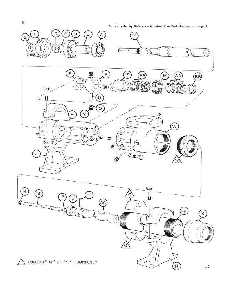
The Moyno progressing cavity pump is a single-screw rotary pump. The pumping action is created by the single helical rotor rolling eccentrically in the double threaded helix of the stator. In its revolution, the rotor forms in conjunction with the stator a series of sealed cavities 180 degrees apart. As the rotor turns the cavities progress from the suction to the discharge. As one cavity diminishes, the opposing cavity is increasing at exactly the same rate. Thus, the sum of the two discharges is a constant volume. The result is a pulsation-less positive displacement flow with no valves.
WARNING 1. Enclose all rotating belts, pulleys, drive shafts, etc., to
comply with acceptable industry safety standards for rotating equipment. Failure to comply could result in personal injury.
2. All pulleys have speed limitations. Refer to pulley manufacturer’s literature for specifications and follow all recommendations, to prevent personal injury.
NAMEPLATE DATA
The Moyno Pump nameplate, located on the bearing housing, carries the serial number, frame size, and type designation. All are extremely important and must be used when ordering spare parts.
Record the nameplate data of your pump in the spaces provided in the heading of Page 3.
Moyno Pumps are identified by Frame and Type. Pump Frame is essentially an indication of size. It consists of a number, a letter, and a number (i.e. 2L6). The first number indicates the number of stages in the pumping elements. The letter indicates the model. The final number indicates the size of the rotor-stator pumping elements. A frame 2L6 pump, therefore, has two stages of size 6 pumping elements.
The “L” in the frame size indicates a standard relationship between the housing, bearings, and drive shaft and the size of the pumping elements. Many variations may be made by adapting smaller element sizes to a larger drive end size. This may be necessary due to the severity of a specific pumping application. In cases where the drive end (housing, bearings, and drive shaft) is one size larger than
the element size normally used, the pump is referred to as an “M” frame pump (i.e. 3M4). If the drive end is two sizes larger than the element size, the pump is referred to as a “P” frame. Thus, a frame 3L6, 3M4, and 3P3 would all use a common drive end.
Type designation is a series of letters which identify the “Materials of Construction” in component groups of parts. The usual type designation will consist of three letters.
The first letter identifies the material of the suction housing casting or the body casting where the bearing housing is a part of the suction housing. C — Cast Iron E — Alloy cb-20 Stainless H — Hastelloy “C” M — Monel S — 316 Stainless Steel W — Cast Steel X — Special to application
The second letter indicates the material used in the drive shaft, pins, connecting rod, rotor, and other minor metallic parts in contact with the material being pumped. D — Alloy Steel E — Alloy cb-20 Stainless G — 416 Stainless Steel H — Hastelloy “C” J — 17-4 PH Stainless Steel M — Monel S — 316 Stainless Steel X — Special to application
The third letter determines the material of the stator. It identifies only the stator material and not that of the tube in which the stator is placed. B — EPDM 300, 70 Durometer C — Buna “N” 103, 50 Durometer D — Tool Steel E — Buna “N” 110, 70 Durometer F — Viton 500, 75 Durometer G — 416 Stainless Steel H — Hastelloy “C” J — 17-4 PH Stainless Steel K — Hypalon 800, 70 Durometer M — Buna “N” 100M. 70 Durometer P — Thiokol 70 Durometer Q — Buna “N” 100, 700 Durometer R — Natural Rubber 200, 55 Durometer T — Teflon 15% glass U — Urethane 70 Durometer X — Special to application Z — Buna “N” 150, 70 Durometer
• 2

* ADD THIRD LETTER OF TYPE DESIGNATION TO COMPLETE PART NO. EX: TYPE CDQ PUMP – ADD Q TO BASIC NUMBER OF STATOR. ** Bearing Kit includes Items A thru G *** Connecting Rod Kit includes items Q thru V. + see pages 5 – 6 for variations
“L6” DRIVE END PARTS TYPE DESIGNATIONS
Select type column corresponding to type designation at left. Order by part number Refer to frame size to select proper rotor and stator.
REF. NO.
DESCRIPTION
CDQ CDR CDB CDF
Part No.
CDD CDG CDT
Part No.
CSQ CSR CSB CSF
Part No.
CSG CSD CST
Part No.
SSQ SSR SSB SSF
Part No.
SSG SST
Part No. A. Ball Bearing (Radial) A06291 A06291 A06291 A06291 A06291 A06291 B. Ball Bearing (Thrust) A06301 A06301 A06301 A06301 A06301 A06301 C. Bearing Spacer A06331 A06331 A06331 A06331 A06331 A06331 D. Bearing Lock Nut A06581 A06581 A06581 A06581 A06581 A06581 E. Bearing Lock Washer A06591 A06591 A06591 A06591 A06591 A06591 F. Grease Seal (Radial) A06611 A06611 A06611 A06611 A06611 A06611 G. Grease Seal (Thrust) A06621 A06621 A06621 A06621 A06621 A06621
Bearing Kit** K06291 K06291 K06291 K06291 K06291 K06291 H. Bearing Housing A06051 A06051 A06051 A06051 A06051 A06051 I. Bearing Cover Plate A06341 A06341 A06341 A06341 A06341 A06341 J. Pump Support with Cap A06371 A06371 A06371 A06371 A06371 A06371 K. Shaft Collar A06491 A06491 A06491 A06491 A06491 A06491 M. Lantern Ring A06571 A06571 A06571 A06571 A06571 A06571 N. Stator Support with cap (All but 9P3 A06381 A06381 A06381 A06381 A06381 A06381
9P3 only A06382 ---------- A06382 ---------- A06382 ---------- O. Support Bushing 3M4, 3P3, 6P3 only A06711 A06711 A06711 A06711 A06711 A06712
Support Bushing 3P3 only A04711 A06711 A04711 A06711 A04711 A06711 P. Pin Retainer A06501 A06501 A06501 A06501 A06501 A06501 Q. Retaining Screw Washer A06731 A06731 A06731 A06731 A06731 A06731 R. Connecting Rod Washer A06531 ---------- A06531 ---------- A06531 ----------
All but Type F A0653Q ---------- A0653Q ---------- A0653Q ---------- CDF, CSF, SSF A0653F ---------- A0653F ---------- A0653F ----------
S. Connecting Rod B0625D B0625D B0625S B0625S B0625S B0625S T. Rotor Pin B0645D B0645D B0645S B0645S B0645S B0645S U. Shaft Pin B0646D B0646D B0646S B0646S B0646S B0646S V. Drive Pin Retaining Screw B0654D B0654D B0654S B0654S B0654S B0654S
Connecting Rod Kit*** All but Type F K0625D K0625D K0625S K0625S K0625S K0625S CDF, CSF, SSF K0625D ---------- K0625D ---------- K0625D ----------
W. Suction Housing B06021 B06021 B06021 B06021 B06026 B06026 X. Reducer 1L6, 2L6, 3L6, 6M4 B06091 B06091 B06091 B06091 B06096 B06096
3M4, 6P3 B04091 B04092 B04091 B04092 B04096 B04097 3P3 B03091 B03092 B03091 B03092 B03096 B03097 9P3 B04092 ---------- A04092 ---------- B04097 ----------
Y. Drive Shaft + B06261 B06261 B06266 B06266 B06266 B06266 Z. Packing Gland B0641D B0641D B0641S B0641S B0641S B0641S
AA. Packing + B06421 B06421 B06425 B06425 B06425 B06425 BB. Packing Washer B0665D B0665D B0665S B0665S B0665S B0665S CC. Adapter Bushing 3M4, 6P3 B06511 B06512 B06511 B06512 B06516 B06517
3P3 only B06513 B06511 B06513 B06511 B06518 B06516 9P3 only B06512 ---------- B06512 ---------- B06517 ----------
FF. Stator Frame 1L6 C4106* C4106* C4106* C4106* C5106* C5106* Frame 2L6 C4206* C4206* C4206* C4206* C5206* C5206* Frame 3L6 C4306* C4306* C4306* C4306* C5306* C5306* Frame 3M4 C4304* C4304* C4304* C4304* C5304* C5304* Frame 6M4 C4604* C4604* C4604* C4604* C5604* C5604* Frame 3P3 C4303* C4303* C4303* C4303* C5303* C5303* Frame 6P3 C4603* C4603* C4603* C4603* C5603* C5603* Frame 9P3 C4903* C4903* C4903* C4903* C5903* C5903*
GG. Rotors Frame 1L6 + C71061 C71061 C81061 C81061 C81061 C81061 Frame 2L6 + C72061 C72061 C82061 C82061 C82061 C82061 Frame 3L6 + C73061 C73061 C83061 C83061 C83061 C83061 Frame 3M4 + M73041 M73041 M83041 M83041 M83041 M83041 Frame 6M4 + C76041 C76041 C86041 C86041 C86041 C86041 Frame 3P3 + P73031 P73031 P83031 P83031 P83031 P83031 Frame 6P3 + P76031 P76031 P86031 P86031 P83031 P83031 Frame 9P3 + P79031 P79031 P89031 P89031 P89031 P89031
3

A typical type designation such as CDQ would result in the following:
C = Cast Iron Suction Housing D = Carbon Steel Internals including drive shaft, pins,
connecting rod, rotor, and other minor metallic parts in contact with the material being pumped
0 = Buna ‘N’ Synthetic Rubber Stator (70 durometer) Also included on the nameplate is the three-character
trim code designation. This only appears on pumps which have semi-standard or special construction. The first letter identifies sealing variations, the second character indentifies internal variations, and the third letter identifies rotor variations.
On page 5 of this manual are variations available for modifying pumps to meet specialized pumping conditions. If the trim code of your pump is other than “AAA", contact your nearest Moyno representative for clarification. Do not use any variation unless you have determined that it is compatible with your application. INSTRUCTIONS FOR DISASSEMBLY AND ASSEMBLY
Frames 1L6, 2L6, 3L6, 3M4, 6M4, 3P3, 6P3, 9P3 Disassembly Procedure 1. Disconnect the power source. 2. Close the suction and discharge valves to isolate the
pump from the line. 3. Turn off flush water to packing or rotary seal if used. 4. Remove drain plug in suction housing to drain away
any fluid remaining in pump. 5. Place a support block under suction housing in area of
drain plug. Wooden blocks are sufficient. The purpose Is to prevent undue stress on pump support when pump is disassembled.
6. Disconnect piping from stator end of pump. 7. Stator Removal - With pipe wrench or strap wrench
remove discharge reducer (X). Remove cap of stator support and with strap wrench or pipe wrench, unscrew the stator (FF) from the suction housing. Pull Stator off the rotor.
8. Rotor Removal - The rotor (GG) is removed with the connecting rod (S) and rotor pin (T) as a unit. Removal of the unit is accomplished by removing the two drive pin retaining screws (V) located in the shaft collar (K). This step reveals the shaft drive pin (U) which is removed by driving the pin from the drive shaft (Y) with a small punch or drift pin. Slide the shaft collar toward the packing gland (Z) and remove the retaining screw washers (Q) from each side of the drive shaft. The rotor and connecting rod can now be removed by pulling them from the pump. To disassemble, clamp the connecting rod (S) by its mid-section in a vise and, with a drift pin, drive the pin retainer (P) from the head of the rotor. The rotor pin (T) can now be removed from the rotor freeing the connecting rod. Remove the connecting rod washers (R) if present.
9. To remove packing (AA), remove nuts holding packing gland (Z). Slip packing gland from studs, remove packing rings, lantern ring (M), and remaining packing rings. Packing rings can be removed with a standard packing puller. Note: If step 10 is to be performed, it should precede step 9 as packing can then be removed by freeing packing gland and driving packing, lantern ring, and packing washer (BB) from housing using a small rod. Rod should enter where stator screws into
suction housing. Place rod on pack-ing washer and tap. Entire set should easily exit from opposite end of stuffing box.
10. Drive Shaft & Bearing Removal - With rotor removed it is now possible to remove the drive shaft and bearings as a sub-assembly. Remove the four cap screws holding the bearing cover plate (I) and slip from shaft. Insert a bar or rod into the hollow end of drive shaft (Y) where it enters the suction cavity. By tapping on the rod the entire assembly will be forced from the bearing housing. To disassemble, remove bearing lock nut (D) and bearing lock washer (E). Using an arbor press remove radial bearing (A), bearing spacer (C), and thrust bearing (B). Apply pressure to inner race only. When replacing drive shaft and/or bearings, it is recommended that both grease seals be replaced. Grease seals are pressed into the bearing housing and bearing cover plate.
Assembly Procedure
Moyno pumps are reassembled in the reverse order of disassembly with special notes as outlined below: 1. Always replace all old washers, “O” rings, and packing.
We also recommend replacing grease seals when new bearings are installed.
2. Bearing Shaft Assembly - When installing new bearings, make sure that they are seated against the shoulder on the shaft. Replace bearing lock washer and bearing lock nut. Tighten bearing lock nut securely. Bend tab down onto lock nut to prevent loosening of nut. Make sure that the shaft collar, packing gland, and packing washer are installed on the drive shaft as the hollow end emerges in the bearing housing and approaches the stuffing box area. When replacing the bearing cover plate, tighten all cap screws evenly to prevent damage to the bearing cover plate and thrust grease seal. Do not over-lubricate bearings. (See Maintenance)
3. When installing the connecting rod, make sure that the hole in the rod is aligned with the holes in the drive shaft and shaft collar before inserting the pin. Always use retaining screw washers and make sure that the hollowed end of the retaining screw fits over the end of the shaft pin to ensure a tight fit. Retaining screws must seat on retaining screw washers and not on pin.
4. When replacing packing, insert four rings on the shaft, the lantern ring, and then four more rings. This will allow the lantern ring to line up with the grease fitting on the stuffing box. Make sure you stagger the ends of the packing rings. When installing the new packing, you may find that all but one ring will go on the drive shaft. When the pump has run for a short time and the new packing is compressed, this final ring can be installed.
5. When installing the stator on the rotor, it is best to lubricate the rotor with water (or a lubricant compatible with the rubber in the stator) to allow the stator to slip on easier. (Grease or oil Is not compatible with type “R” or “B” stators.) When replacing the stator, always tighten it with the pipe wrench on the end of the stator nearest the suction housing. This will prevent it from binding and damaging the threads.
4
If your stator has a stainless steel sleeve, use a teflon tape or similar material on the threads before replacing -- on all stators with a carbon steel sleeve, use pipe dope.
6. Caution: Dry operation Is harmful to the pump. Always fill the pump with fluid to be handled prior to start up. Check any valves In discharge line to determine that no restrictions exist.
MAINTENANCE
The Moyno pump has been designed for a minimum of maintenance, the extent of which is routine lubrication and adjustment of packing and infrequent lubrication of the bearings. The pump is one of the easiest to work on in that the main elements are very accessible and require few tools to disassemble. Packing
The Moyno pump is normally furnished with die formed packing. The packing may be either grease lubricated through a grease fitting in the stuffing box or have plumbing connected to the housing to allow a water flush. (See Water Flush of Packing)
Packing gland adjusting nuts should be evenly adjusted so they are little more than finger tight. Over-tightening of the packing gland may result in premature packing failure and possible damage to the shaft and gland. When the packing is new, frequent minor adjustments are recommended for the first few hours of operation in order to compress and seat the packing. Greasing the packing often but with limited quantities of grease is the best practice. This can be done through a grease fitting which leads to a lantern ring in the mid-section of the packing. Do not use a one-piece spiral wrap of packing.
Water Flush of Packing
When the material being pumped is abrasive in nature, it may be advantageous to flush the packing to prevent leakage under packing and excessive shaft wear.
Clean water can be injected through a 1/8” NPT tapped hole that normally houses the grease fitting for lubricating the packing. The water can be permitted to leak axially along the shaft In either direction or can be removed from the second tapped hole In the stuffing box. In both cases, the discharge from the stuffing box should be throttled slightly to maintain 10-15 PSI higher pressure in the stuffing box than is present In the suction housing.
This is a basic arrangement, other variations can be used. (1) Throttling Valve (2) Pressure Guage (3) Pressure Regulating Valve Bearings
The Moyno pump is equipped with ball bearings in the drive end size L2 through L10. The bearings are lubricated at the factory and do not need additional lubrication for at least 1500 hours of normal operation.
When relubricating the bearings, the bearing-shaft assembly should be removed (See Disassembly Instructions) and cleaned of old grease. Add only enough grease to fill the area between the bearings 1/3 full. Add a few drops of oil to bearing seals before reassembling. It is normal for bearings to run warm to the touch for the first few hours of operation.
Any type of Ep Lithium soap base grease is satisfactory for bearing lubrication. The use of Sodium or Calcium base grease is not recommended.
The following is a partial listing of approved bearing lubricants: Dow Corning DC 33 Keystone Lubricating Co. Keystone #89 Texaco Regal AFB2 Shell Oil Co. Cyprina #3 Humble Oil & Refining Co. Beacon 325 American Oil Co. Supermil Grease #A72832 Mobil EP1 Shell Oil Co. Alvania #2
VARIATIONS OF STANDARD PARTS Following are variations available for modifying pumps to
meet specialized pumping conditions. If the trim code of your pump is other than “AAA,” contact your nearest Moyno representative for clarification. Do not modify your pump with any variation unless you have determined that it is compatible with your application.
The three.character trim code is designed as follows. The first character identifies any sealing variations, the second character identifies any internal variations, and the third character identifies any rotor variations.
5
The trim code “AAA” represents a pump with standard features. Deviations from standard are to be indicated by changing the appropriate character from the choices listed. When two or more letters are combined, dashes are used to separate the three areas of the trim code for clarity. SEALING VARIATIONS
A — BRAIDED TEFLON & GRAPHITE PACKING, (Black) Standard to all lines except Quick Disassembly pumps. Optional on Quick Disassembly pumps.
C — BRAIDED TEFLON PACKING, (White) Optional
packing on all lines. D — DOUBLE MECHANICAL SEAL, Optional on all
lines. Not offered on #2 “L” frame. F — BRAIDED TEFLON FOOD GRADE PACKING,
(White) Standard on all Quick Disassembly pumps. Optional on all other lines.
G — 100% GRAPHITE PACKING, (Gray) Optional to all
lines. S — SINGLE MECHANICAL SEAL, Optional on all lines. W — WATER FLUSH, Optional on all lines. X — Special to application.
INTERNAL VARIATIONS A — Standard plated shaft B — Non-plated shaft C — Solid drive shaft configuration D — Grit seal, for “L” frame only E — Extension tube with extended auger F — Extended drive shaft (for back stop or large pulley) G — Ceramic coating S — Shaft sleeve X — Special to application ROTOR VARIATIONS A — Standard size with chrome plating B — Non-plated (no plating) C — Standard undersize E — Standard oversize F — Counter clockwise rotation (Centennial line only) G — Ceramic coating X — Special to application
PACKING VARIATIONS listed are common to most type
designations. Others may be specified by changing the last digit to the following:
1 = Standard on all type CDQ pumps 3 = Standard on all type CDR & SSR pumps 5 = Standard on all type SSQ pumps 7 = Optional--Solid Braided Teflon 8 = Optional--Teflon Impregnated white asbestos
DRIVESHAFTS shown have hard-chrome plating on the packing wear area. If non-plated driveshafts are required, select the standard part number and change the last digit to next higher number. Example: B06261 to B06262.
L6 STANDARD HARDWARE
ITEM SIZE #REO. Bearing Cover Plate Screw 1L X 3/8D-16 4 Lock Washer 4 Packing Gland Stud 3 3/8LX 1/2D-14 2 Nut 2 Stator & Pump Support Screws 1 1/2L X 1/2D-13 4 Suction Housing Bolts 2L X 1/2D-13 4 Lock Washers 4 Suction Housing Drain Plug 1/2 NPT 3 Grease Fitting on Stuffing box 1/8 NPT 1 Drain Plug on Stuffing Box 1/8 NPT 1 Pipe Plug on Bearing Housing 1/8 NPT 1 Hex Key 5/16 1
RECOMMENDED SPARE PARTS
The Moyno pump has been designed and built with all
wearable parts replaceable. A recommended inventory of spare parts is dependent upon the application and importance of continued operation.
For the shortest possible down time, we recommend the following parts be stocked:
1 - Rotor 1 - Stator 1 - Connecting Rod Kit
The above is only a suggested list. For further assistance in determining what you’ll need for your application, contact your Moyno representative.
6
© 1993 by Moyno, Inc. ® Moyno is a registered trademark of Moyno, Inc. Moyno, Inc. is a Unit of Robbins & Myers, Inc. Teflon® is a registered trademark of DuPont
Section: L and J FRAME PUMPS Page: 1 Date: (Revision 9/94)
OPERATION – ASSEMBLY INSTRUCTIONS AND PARTS LIST FOR
“L8” DRIVE END (FRAME SIZES 1L8, 2L8, 3L8, 3M6, 3P4, 6P4, 9P4)
GENERAL
The Moyno® Pump is one of the most versatile pumps available, It has been proven in thousands of applications over the past 40 years. It is backed by the experience gained over the years, both in application and manufacturing know-how.
The Moyno progressing cavity pump is a single-screw rotary pump. The pumping action is created by the single helical rotor rolling eccentrically in the double threaded helix of the stator. In its revolution, the rotor forms in conjunction with the stator a series of sealed cavities 180 degrees apart. As the rotor turns, the cavities progress from the suction to the discharge. As one cavity diminishes, the opposing cavity is increasing at exactly the same rate. Thus, the sum of the two discharges is a constant volume. The result is a pulsation-less positive displacement flow with no valves. NAMEPLATE DATA
The Moyno Pump nameplate, located on the bearing housing, carries the serial number, frame size, and type designation. All are extremely important and must be used when ordering spare parts.
Record the nameplate data of your pump in the spaces provided in the heading of Page 3.
Moyno Pumps are identified by Frame and Type. Pump Frame is essentially an indication of size. It consists of a number, a letter, and a number (i.e. 2L8). The first number indicates the number of stages in the pumping elements. The letter indicates the model. The final number indicates the size of the rotor-stator pumping elements. A frame 2L8 pump, therefore, has two stages of size 8 pumping elements.
The “L” in the frame size indicates a standard relationship between the housing, bearings, and drive shaft and the size of the pumping elements. Many variations may be made by adapting smaller element sizes to a larger drive end size. This may be necessary due to the severity of a specific pumping application. In cases where the drive end (housing, bearings, and drive shaft) is one size larger than the element size normally used, the pump is referred to as an “M” frame pump (i.e. 3M6). If the drive end is two sizes larger than the element size, the pump is referred to as a “P” frame. Thus, a frame 3L8, 3M6 and 3P4 would all use a common drive end.
Type designation is a series of letters which identify the “Materials of Construction” in
component groups of parts. The usual type designation will consist of three letters.
The first letter identifies the material of the suction housing casting or the body casting where the bearing housing is a part of the suction housing.
The second letter indicates the material used in the drive shaft, pins, connecting rod, rotor, and other minor metallic parts in contact with the material being pumped.
The third letter determines the material of the stator. It identifies only the stator material and not that of the tube in which the stator is placed.
A typical type designation such as CDQ would result in the following:
C = Cast Iron Suction Housing D = Hardened Steel Internals including drive
shaft, pins, connecting rod, rotor, and other minor metallic parts in contact with the material being pumped
Q = Nitrile Synthetic Rubber Stator (70 durometer)
The following letters identify the actual materials that are used in standard construction: B - EPDM Q - Nitrile (70 durometer) C - Cast Iron R - Natural Rubber (55 durometer) D - Hardened Steel S - Stainless Steel, type #316 F - Fluoroelastomer T - Teflon (glass impreg- nated) G - Stainless Steel, #416
Also included on the nameplate is the three-character trim code designation. This only appears on pumps which have semi-standard or special construction. The first letter identifies sealing variations, the second character indentifies internal variations, and the third letter identifies rotor variations. On page 5 of this manual are variations available for modifying pumps to meet specialized pumping conditions. If the trim code of your pump is other than “AAA”, contact• your nearest Moyno representative for clarification. Do not use any variation unless you have determined that it is compatible with your application.

* ADD THIRD LETTER OF TYPE DESIGNATION TO COMPLETE PART NUMBER EX: TYPE CDQ PUMP – ADD Q TO BASIC NUMBER OF STATOR ** Bearing Kit includes Items A thru G *** Connecting Rod Kit includes items Q thru U + see pages 5 - 6 for variations
“L8” DRIVE END PARTS TYPE DESIGNATIONS
Select type column corresponding to type designation at left. Order by part number Refer to frame size to select proper rotor and stator.
REF. NO.
DESCRIPTION
CDQ CDR CDB CDF
Part No.
CDD CDG CDT
Part No.
CSQ CSR CSB CSF
Part No.
CSD CSG CST
Part No.
SSQ SSR SSB SSF
Part No.
SSG SST
Part No.
A. Ball Bearing (Radial) A08291 A08291 A08291 A08291 A08291 A08291 B. Ball Bearing (Thrust) A08301 A08301 A08301 A08301 A08301 A08301 C. Bearing Spacer A08331 A08331 A08331 A08331 A08331 A08331 D. Bearing Lock Nut A08581 A08581 A08581 A08581 A08581 A08581 E. Bearing Lock Washer A08591 A08591 A08591 A08591 A08591 A08591 F. Grease Seal (Radial) A08611 A08611 A08611 A08611 A08611 A08611 G. Grease Seal (Thrust) A08621 A08621 A08621 A08621 A08621 A08621
Bearing Kit** K08291 K08291 K08291 K08291 K08291 K08291 H. Bearing Housing A08051 A08051 A08051 A08051 A08051 A08051 I. Bearing Cover Plate A08341 A08341 A08341 A08341 A08341 A08341 J. Pump Support A08371 A08371 A08371 A08371 A08371 A08371 K. Shaft Collar A08491 A08491 A08491 A08491 A08491 A08491 M. Lantern Ring A08571 A08571 A08571 A08571 A08571 A08571 N. Stator Support 1 L8, 2L8, 3L8 A08381 A08381 A08381 A08381 A08381 A08381
3M6, 3P4, 6P4, 9P4 A08382 A08382 A08382 A08382 A08382 A08382 O. Support Bushing 3P4 A08711 A06712 A08711 A06712 A08711 A06712
9P4 A06712 ---------- A06712 ---------- A06712 ---------- P. Pin Retainer A08501 A08501 A08501 A08501 A08501 A08501 Q. Retaining Screw Washer A08731 A08731 A08731 A08731 A08731 A08731 R. Connecting Rod Washer A08531 A08531 A08531 A08531 A08531 A08531 S. Connecting Rod B0825D B0825D B0825S B0825S B0825S B0825S T. Rotor Pin or Shaft Pin B0845D B0845D B0845S B0845S B0845S B0845S U. Drive Pin Retaining Screw B0854D B0854D B0854S B0854S B0854S B0854S
Connecting Rod Kit*** K0825D K0825D K0825S K0825S K0825S K0825S V. Suction Housing B08021 B08021 B08021 B08021 B08026 B08026
W. Reducer 1L8, 2L8, 3L8 only B08091 B08091 B08091 B08091 B08096 B08096 3M6 B06091 B06091 B06091 B06091 B06096 B06096 3P4 B04091 B04092 B04091 B04092 B04096 B04097 6P4 B06091 B06091 B06091 B06091 B06096 B06096 9P4 B08092 ---------- ---------- ---------- B08097 ----------
X. Drive Shaft + B08261 B08261 B08266 B08266 B08266 B08266 Y. Packing Gland B0841D B0841D B0841S B0841S B0841S B0841S Z. Packing + B08421 B08421 B08425 B08425 B08425 B08425
AA. Packing Washer B0865D B0865D B0865S B0865S B0865S B0865S BB. Adapter Bushing
3M6, 6P4 B08511 B08511 B08511 B08511 B08516 B08516 3P4 Only B08512 B08513 B08512 B08513 B08517 B08518 9P4 Only B08513 ---------- B08513 ---------- B08518 ----------
EE. Stator Frame 1L8 C4108* C4108* C4108* C4108* C5108* C5108* Frame 2L8 C4208* C4208* C4208* C4208* C5208* C5208* Frame 3M6 C4306* C4306* C4306* C4306* C5306* C5306* Frame 3P4 C4304* C4304* C4304* C4304* C5304* C5304* Frame 6P4 C4604* C4604* C4604* C4604* C5604* C5604* Frame 9P4 C4904* ---------- C4904* ---------- C5904* ----------
FF. Rotors Frame1L8 + C71081 C71081 C81081 C81081 C81081 C81081 Frame 2L8 + C72081 C72081 C82081 C82081 C82081 C82081 Frame 3L8 + C73081 C73081 C83081 C83081 C83081 C83081 Frame 3M6 + M73061 M73061 M83061 M83061 M83061 M83061 Frame 3P4 + P73041 P73041 P83041 P83041 P83041 P83041 Frame 6P4 + P76041 P76041 P86041 P86041 P86041 P86041 Frame 9P4 + P79041 ---------- P89041 ---------- P89041 ----------
3
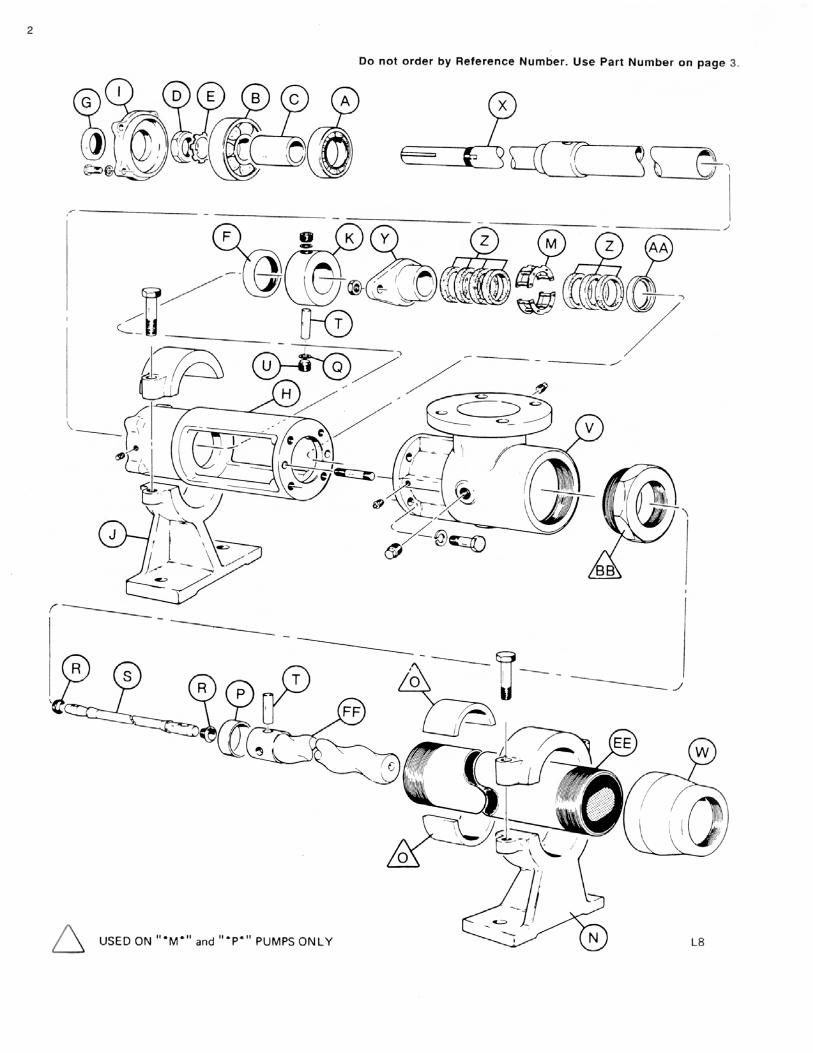
INSTRUCTIONS FOR DISASSEMBLY AND ASSEMBLY Frames 1L8, 2L8, 3L8, 3M6, 3P4, 6P4, 9P4
Disassembly Procedure 1. Disconnect the power source. 2. Close the suction and discharge valves to isolate the
pump from the line. 3. Turn off flush water to packing or rotary seal if used. 4. Remove drain plug in suction housing to drain away
any fluid remaining in pump. 5. Place a support block under suction housing in area of
drain plug. Wooden blocks are sufficient. The purpose is to prevent undue stress on pump support when pump is disassembled.
6. Disconnect piping from stator end of pump. 7. Stator Removal - With pipe wrench or strap wrench
remove discharge reducer (W). Remove cap of stator support and with strap wrench or pipe wrench, unscrew the stator (EE) from the suction housing. Pull Stator off the rotor.
8. Rotor Removal - The rotor (FF) is removed with the connecting rod (S) and rotor pin (T) as a unit. Removal of the unit is accomplished by removing the two drive pin retaining screws (U) located in the shaft collar (K). This step reveals the shaft drive pin (T), which is removed by driving the pin from the drive shaft (X) with a small punch or drift pin. Slide the shaft collar toward the packing gland (Y) and remove the retaining screw washers (Q) from each side of the drive shaft. The rotor and connecting rod can now be removed by pulling them from the pump. To disassemble, clamp the connecting rod (S) by its mid-section in a vise and, with a drift pin, drive the pin retainer (P) from the head of the rotor. The rotor pin (T) can now be removed from the rotor freeing the connecting rod. Remove the connecting rod washers (R) if present.
9. To remove packing (Z), remove nuts holding packing gland (Y). Slip packing gland from studs, remove packing rings, lantern ring (M), and remaining packing rings. Packing rings can be removed with a standard packing puller. Note: If step 10 is to be performed, it should precede step 9 as packing can then be removed by freeing packing gland and driving packing, lantern ring, and packing washer (AA) from housing using a small rod. Rod should enter where stator screws into suction housing. Place rod on packing washer and tap. Entire set should easily exit from opposite end of stuffing box.
10. Drive Shaft & Bearing Removal - With rotor removed it is now possible to remove the drive shaft and bearings as a sub-assembly. Remove the four cap screws holding the bearing cover plate (I) and slip from shaft. Insert a bar or rod into the hollow end of drive shaft (X) where it enters the suction cavity. By tapping on the rod the entire assembly will be forced from the bearing housing.
To disassemble, remove bearing lock nut (D) and bearing lock washer (E). Using an arbor press remove radial bearing (A), bearing spacer (C), and thrust bearing (B). Apply pressure to inner race only. When replacing drive shaft and/or bearings, it is recommended that both grease seals be replaced. Grease seals are pressed into the bearing housing and bearing cover plate.
Assembly Procedure
Moyno pumps are reassembled in the reverse order of disassembly with special notes as outlined below: 1. Always replace all old washers, “0” rings and packing.
We also recommend replacing grease seals when new bearings are installed.
2. Bearing Shaft Assembly - When installing new bearings, make sure that they are seated against the shoulder on the shaft. Replace bearing lock washer and bearing lock nut. Tighten bearing lock nut securely. Bend tab down onto lock nut to prevent loosening of nut. Make sure that the shaft collar, packing gland, and packing washer are installed on the drive shaft as the hollow end emerges in the bearing housing and approaches the stuffing box area. When replacing the bearing cover plate, tighten all cap screws evenly to prevent damage to the bearing cover plate and thrust grease seal. Do not over-lubricate bearings. (See Maintenance)
3. When installing the connecting rod, make sure that the hole in the rod is aligned with the holes in the drive shaft and shaft collar before inserting the pin. Always use retaining screw washers and make sure that the hollowed end of the retaining screw fits over the end of the shaft pin to ensure a tight fit. Retaining screws must seat on retaining screw washers and not on pin.
4. When replacing packing, insert three rings on the shaft, the lantern ring, and then four more rings. This will allow the lantern ring to line up with the grease fitting on the stuffing box. Make sure you stagger the ends of the packing rings. When installing the new packing, you may find that all but one ring will go on the drive shaft. When the pump has run for a short time and the new packing is compressed, this final ring can be installed.
5. When installing the stator on the rotor, it is best to lubricate the rotor with water (or a lubricant compatible with the rubber in the stator) to allow the stator to slip on easier. (Grease or oil is not compatible with type “R” or “B” stators.) When replacing the stator, always tighten it with the pipe wrench on the end of the stator nearest the suction housing. This will prevent it from binding and damaging the threads. If your stator has a stainless steel sleeve, use a teflon tape or similar material on the threads before replacing -- on all stators with a carbon steel sleeve, use pipe dope.
4

6. Caution: Dry operation is harmful to the pump. Always fill the pump with fluid to be handled prior to start up. Check any valves in discharge line to determine that no restrictions exist.
MAINTENANCE
The Moyno pump has been designed for a
minimum of maintenance, the extent of which is routine lubrication and adjustment of packing and infrequent lubrication of the bearings. The pump is one of the easiest to work on in that the main elements are very accessible and require few tools to disassemble. Packing
The Moyno pump is normally furnished with die formed packing. The packing may be either grease lubricated through a grease fitting in the stuffing box or have plumbing connected to the housing to allow a water flush. (See Water Flush of Packing)
Packing gland adjusting nuts should be evenly adjusted so they are little more than finger tight. Over-tightening of the packing gland may result in premature packing failure and possible damage to the shaft and gland. When the packing is new, frequent minor adjustments are recommended for the first few hours of operation in order to compress and seat the packing. Greasing the packing often but with limited quantities of grease is the best practice. This can be done through a grease fitting which leads to a lantern ring in the mid-section of the packing. Do not use a one-piece spiral wrap of packing. Water Flush of Packing
When the material being pumped is abrasive in nature, it may be advantageous to flush the packing to prevent leakage under packing and excessive shaft wear. Clean water can be injected through a 1/8” NPT tapped hole that normally houses the grease fitting for lubricating the packing. The water can be permitted to leak axially along the shaft in either direction or can be removed from the second tapped hole in the stuffing box. In both cases, the discharge from the stuffing box should be throttled slightly to maintain 10-15 PSI higher pressure in the stuffing box than is present in the suction housing.
This is a basic arrangement, other variations can be used. (1) Throttling Valve (2) Pressure Guage (3) Pressure Regulating Valve This is a basic arrangement, other variations can be used. (1) Throttling Valve (2) Pressure Guage (3) Pressure Regulating Valve
Bearings The Moyno pump is equipped with ball bearings in
the drive end size L2 through L10. The bearings are lubricated at the factory and do not need additional lubrication for at least 1500 hours of normal operation.
When relubricating the bearings, the bearing-shaft assembly should be removed (See Disassembly in-structions) and cleaned of old grease. Add only enough grease to fill the area between the bearings 1/3 full. Add a few drops of oil to bearing seals before reassembling. It is normal for bearings to run warm to the touch for the first few hours of operation.
Any type of Ep Lithium soap base grease is satisfactory for bearing lubrication. The use of Sodium or Calcium base grease is not recommended.
The following is a partial listing of approved bearing lubricants: Dow Corning DC 33 Keystone Lubricating Co. Keystone #89 Texaco Regal AFB2 Shell Oil Co. Cyprina #3 Humble Oil & Refining Co. Beacon 325 American Oil Co. Supermil Grease #A72832 Mobil EP1 Shell Oil Co. Alvania #2
VARIATIONS OF STANDARD PARTS
ROTORS identified on parts listing are standard size with hard-chrome plated surface. Other variations of rotor size and finish may be ordered by selecting the standard rotor part number and changing the last digit of the rotor number as follows:
2 = Standard size, non-plated 3 = Undersize, chrome-plated 4 = Undersize, non-plated 5 = Oversize, chrome-plated
Do not change rotor sizes without consulting your local Moyno Sales Office. These variations are used for certain specialized pumping conditions only.
5

PACKING VARIATIONS listed are common to most type designations. Others may be specified by changing the last digit to the following: 1 = Standard on all type CDQ pumps 3 = Standard on all type CDR & SSR pumps 5 = Standard on all type SSQ pumps 7 = Optional--Solid Braided Teflon 8 = Optional--Teflon impregnated white asbestos DRIVE SHAFTS shown have hard-chrome plating on the packing wear area. If non-plated drive shafts are required, select the standard part number and change the last digit to next higher number. Example: B08261 to B08262.
L8 STANDARD HARDWARE ITEM SIZE # REQ. Bearing Cover Plate Screw
1L X 1/2 D-13 4
Lock Washer 4 Suction Housing Bolt 3 1/4L X 1/2 D-13 4 Lock Washer 4 Stator & Pump Support Screw
2L X 5/8 D-11 4
Packing Gland Stud 4 L 1/2 D-13 2 Nut 1/2 D-13 2 Suction Housing Drain Plug
1/2 D 3
Drain Plug on Stuffing Box
1/8 D 1
Grease Fitting on Stuffing Box
1/8 D 1
Pipe Plug on Bearing Housing
1/8 D 2
Hex Key 9/16 1
RECOMMENDED SPARE PARTS The Moyno pump has been designed and built with all wearable parts replaceable. A recommended inventory of spare parts is dependent upon the application and importance of continued operation. For the shortest possible downtime, we recommend the following parts be stocked:
1 - Rotor 1 - Stator 1 - Connecting Rod Kit
The above is only a suggested list. For further assistance in determining what you’ll need for your application, contact your Moyno representative.
6
© 1988 by Moyno, Inc. ® Moyno is a registered trademark of Moyno, Inc. Moyno, Inc. is a Unit of Robbins & Myers, Inc. Teflon® is a registered trademark of DuPont