Embed Size (px)
Citation preview

CONTENTS
Technical Specification Manual
Page
Article I. General Conditions ................................................... 1 Sec.1 City of Nixa Extension Policies..................................................................1
A. Request for City Utilities Inside the City of Nixa Planning Area .......1
B. Request for City Utilities Outside the City of Nixa Planning Area ....2
Sec.2 City of Nixa Construction Discussion Items...............................................3
A. General ...............................................................................................3
B. Water ..................................................................................................4
C. Water Crossings .................................................................................6
D. Sewer..................................................................................................6
E. Streets .................................................................................................8
F. Underground Electric and Street Lights .............................................8
G. Drainage/Detention ............................................................................9
Sec.3 Service Ownership/Responsibility..............................................................10 Sections 4 thru 19 Reserved
Article II. Water and Sewer Specifications ............................. 11 Sec.20 Excavation and Trenching ........................................................................11
A. Scope ...................................................................................................11
B. General Requirements ........................................................................11
C. Blasting ..............................................................................................11
D. Unauthorized Excavation ...................................................................12
E. Dewatering .........................................................................................12
F. Sheeting and Shoring ..........................................................................12
G. Stabilization .......................................................................................12
H. Trench Excavation .............................................................................13
Sec.21 Installation of Mains ..................................................................................15
A. Standards ............................................................................................15
B. Bedding, Embedment and Backfill…………………………………15
C. Bedding ............................................................................................16
D. Material ……......................................................................................16
E. Trench Backfill...................................................................................16
F. Laboratory Tests……........................................................................17
G. Drainage Maintenance…………………………. .............................17
H. Protection of Trench Backfill in Drainage Course…………………...17
I. Disposal of Excess Excavated Materials………………………….....17
J. Settlement...........................................................................................18
K Seeding and Sodding..........................................................................18
L. Structure Backfill ...............................................................................19

M. Classification of Excavated Materials ...............................................20
Sec.22 PVC Water Piping.....................................................................................20
A. Standards of Materials Selection .......................................................20
B. Permeation of Pipe Walls...................................................................20
C. Used Materials ...................................................................................21
D. Joints ..................................................................................................21
E. Handling.............................................................................................21
F. Cutting Pipe .......................................................................................21
G. Cleaning .............................................................................................21
H. Inspection ...........................................................................................21
I. Alignment ..........................................................................................21
J. Laying Pipe ........................................................................................21
K. Push-on Joints ....................................................................................22
L. Mechanical Joints...............................................................................22
M. Flanged Joints ....................................................................................22
N. Wall Castings .....................................................................................22
O. Connections with Existing Pipelines .................................................22
P. Reaction Anchorage and Blocking ....................................................22
Q. Tracer Wire…………………………………………………………..23
Sec.23 Water Main Design ...................................................................................23
A. Pressure ..............................................................................................23
B. Diameter.............................................................................................24
C. Fire Protection....................................................................................24
D. Flushing..............................................................................................24
E. I s o l a t i o n Valves…………………………………………………24
Sec.24 Fire Hydrants ............................................................................................24
A. Location and Spacing.........................................................................24
B. Valves and Nozzles ............................................................................25
C. Hydrant Leads ....................................................................................25
D. Drainage .............................................................................................25
E. Installation…………………………………………………………..25
Sec.25 Air Relief Valves; Valve, Meter and Blow-off Chambers........................25
A. Location .............................................................................................25
B. Piping .................................................................................................26
C. Chamber Drainage .............................................................................26
D. Installation Standards .........................................................................26
Sec.26 Crossings...................................................................................................26
A. General…... ........................................................................................26
B. Parallel Installation ............................................................................26
C. Line Crossing………………….. ......................................................27
D. Exceptions…….. ...............................................................................27
E. Force Mains…………………………………………………………27
F. Sewer Manholes……………………………………………………. 27
G. Disposal Facilities…………………………………………………...27
H. Above Water Crossings…………………………………………….. 28
I. Underwater Crossings……………………………………………….28
J. Street Crossings……………………………………………………..29
K. Water Services………………………………………………………29
L. Protection of Water Meter Boxes…………………………………...30
Sec.27 Waterline Acceptance Testing…................................................................... 30
A. General……………………………. .................................................30

B. Pressure/Leakage Test..…………………………………………….30
C. Filling and Venting the Line…………………………………………30
D. Testing Equipment Facilities………………………………………...30
E. Test Pressure…………………………………………………………30
F. Test Duration………………………………………………………...30
G. Leak Measurement…………………………………………………..30
H. Allowable Leakage…………………………………………………..30
I. Defects……………………………………………………………….31
J. Repetition…………………………………………………………….31
Sec.28 Waterline Disinfection…...………………………………………………….31
A. General………….................................................................................31
B. Disinfectants….....................................................................................32
C. Feeding.………...................................................................................32
D. Bacteriological Tests………………………………………………...33
E. Re-disinfection……………………………………………………….33
Sec.29 Protection of Potable Water Supply...……………………………………..33
A. Protection of Potable Water Outlets………………………………....33
B. Connections ........................................................................................34
Sec.30 Sewer Pipe................... ..............................................................................34
A. PVC Sewer Pipe…………………………………………………….34
B. Building Sewer ...................................................................................39
C. PVC Force Main .................................................................................39
D. Vitrified Clay Sewer Pipe...................................................................43
E. Ductile Iron Piping……………...........................................................43
Sec.31 Manholes………………… .......................................................................46
A. General ................................................................................................46
B. Materials……………. .......................................................................46
C. Delivery…………………… ..............................................................48
D. Inspection………………….. .............................................................48
E. Construction. ......................................................................................48
F. Waterproofing.....................................................................................48
G. Frames and Covers…..........................................................................48
H. Pipe Connections... ............................................................................49
I. Stubs... ...............................................................................................49
J. Holes…... ...........................................................................................49
K. Painting…..…………………………………………………………49
L. Bench……………………………………………………………….49
M. Corrosion Protection for Manholes…………………………………49
N. Structures in Relation to Streams…………………………………...49
O. Manholes in Relation to Water Mains………………………………49
Sec.32 Sewer Acceptance Testing ......................................................................49
A. Scope... ...............................................................................................49
B. General…… ........................................................................................49
C. Sewer Performance Testing………....................................................50
D. Force Main Performance Testing........................................................51
Sections 33 thru 39 Reserved

Article III. Concrete and Grouting .................................................54
Sec.40 Portland Cement Concrete ........................................................................54
A. Description .........................................................................................54
B. Materials ............................................................................................54
C. Water..................................................................................................54
D. Fine Aggregate ...................................................................................54
E. Course Aggregate...............................................................................54
F. Air-Entrainment .................................................................................55
G. Fly Ash ...............................................................................................55
H. Proportions of Materials ....................................................................56
I. Water Content ....................................................................................56
J. Air Content.........................................................................................56
K. Fly Ash Content .................................................................................56
L. Mix Proportions .................................................................................56
M. General Requirements........................................................................56
Sec.41 Grouting ....................................................................................................57
A. Scope..................................................................................................57
B. Materials ............................................................................................57
C. Execution ...........................................................................................57
Sections 42 thru 49 Reserved
Article IV Streets .....................................................................................58
Sec.50 Portland Cement Concrete Curb & Gutter................................................58
A. Scope of Work ...................................................................................58
B. Materials ............................................................................................58
C. Forms .................................................................................................58
D. Placing Concrete ................................................................................59
E. Finishing ............................................................................................59
F. Joints ..................................................................................................60
G. Curing ................................................................................................60
H. Cold Weather Protection ....................................................................60
I. Curb and Gutter..................................................................................60
J. Backfilling..........................................................................................60
K. Driveway Entrances ...........................................................................60
Sec.51 Portland Cement, Concrete Pavement, and Integral Concrete Curb.........61
A. Scope of Work ...................................................................................61
B. Materials ............................................................................................61
C. Forms .................................................................................................61
D. Placing Concrete ................................................................................62
E. Consolidating and Finishing ..............................................................62
F. Floating, Straightening and Edging ...................................................63
G. Final Surface Finish ...........................................................................63
H. Joints ..................................................................................................63
I. Transverse Joints................................................................................64
J. Longitudinal Joints.............................................................................65
K. Tiebars................................................................................................65
L. Joint Sealer.........................................................................................65
M. Structures ...........................................................................................65

N. Curing ................................................................................................65
O. Cold Weather Protection ....................................................................65
P. Tolerance in Pavement Thickness .....................................................65
Q. Protection and Opening to Traffic .....................................................66
R. Paving by Slip Form ..........................................................................66
S. Integral Curb ......................................................................................66
T. Materials ............................................................................................66
U. Construction Methods ........................................................................67
V. Paving by Slip Forms.........................................................................67
Sec.52 Plant Mix Bituminous Surface Course .....................................................67
A. Scope of Work ...................................................................................67
B. Materials ............................................................................................67
C. Course of Aggregate ..........................................................................68
D. Fine Aggregate ...................................................................................68
E. Mineral Filler .....................................................................................69
F. Composition of Mixtures ...................................................................69
G. Job-Mix Formula ...............................................................................70
H. Changes in Proportions ......................................................................70
I. Gradation Control ..............................................................................70
J. Commercial Mixture ..........................................................................71
K. Weather Limitations...........................................................................71
L. Subgrade Preparation .........................................................................71
M. Tack Coat ...........................................................................................71
N. Preparation of Surface........................................................................71
O. Applications .......................................................................................71
P. Hauling Equipment ............................................................................72
Q Spreading ...........................................................................................72
R. Surface Condition ..............................................................................72
S. Spot Wedging and Leveling Course ..................................................72
T. Joints ..................................................................................................73
Sec.53 Plant Mix Bituminous Base Course..........................................................74
A. Scope of Work ....................................................................................74
B Materials ............................................................................................75
C. Fine Aggregate ...................................................................................75
D. Mineral Filler .....................................................................................75
E. Graded Aggregate ..............................................................................75
F. Compositions of Mixture ...................................................................76
G. Job-Mix Formula ...............................................................................76
H. Changes in Proportions ......................................................................77
I. Gradation Control ..............................................................................77
J. Quality of Asphalt ..............................................................................77
K. Commercial Mixture ..........................................................................77
L. Weather Limitations...........................................................................78
M. Subgrade Preparation .........................................................................78
N. Prime Coat .........................................................................................78
O. Application.........................................................................................78
P. Prime Coat .........................................................................................78
Q. Application.........................................................................................78
R. Transportation ....................................................................................79
S. Spreading ...........................................................................................79
T. Joints ..................................................................................................80

U. Compaction .......................................................................................80
V. Surface Tolerances ............................................................................80
W. Tolerance in Pavement Thickness ....................................................81
X. Method of Measurement ...................................................................81
Y. Basis of Payment...............................................................................81
Sec.54 Aggregate for Base (Rock Base Course) .................................................82
A. Scope of Work ..................................................................................82
B. Type 1 Aggregate..............................................................................82
C. Placement and Compaction...............................................................82
D. Surface Tolerances ............................................................................82
E. Testing Samples ................................................................................82
Sec.55 Sub Grade Preparations ...........................................................................83
A. Scope of Work ..................................................................................83
B. Placement and Compaction...............................................................83
C. Surface Tolerances ............................................................................83
D. Testing Samples ................................................................................83
Sec.56 General Notes ..........................................................................................83
Sec.57 Design Standards for Streets and Roadways ...........................................84
A. Grades ...............................................................................................84
B. Vertical Curves .................................................................................84
C. Horizontal Curves and Super Elevation............................................85
D. Minimum Curb Radii at Intersections...............................................85
E. Intersections ......................................................................................85
F. Pavement Design ..............................................................................85
Sec.58 Street Permit and Inspections Required for all Street Cuts, Bores,
and Curb Cuts ...............................................................................................86 Sections 25-59 Reserved
ARTICLE V. EQUIPMENT .....................................................87
Sec.60 Submersible Pump Station........................................................................87
A. Scope.................................................................................................87
B. General ..............................................................................................87
C. Wet Well/Valve Box Access ............................................................87
D. Sewage Pumping Equipment ............................................................87
E. Data to be Submitted.........................................................................90
F. Shop Tests .........................................................................................91
G. Responsibility ...................................................................................91
H. Pumping Station Electrical System...................................................91
I. Piping ................................................................................................94
J. Valves ...............................................................................................94
K. Painting and Corrosion Protection ....................................................94
L. Factory Tests .....................................................................................95
M. Installation for Pumping Station .......................................................95
N. Access Road ......................................................................................95
O. Security Fencing ...............................................................................95
P. Potable Water....................................................................................95
Q. Grading .............................................................................................95
R. Drawings and Descriptive Data ........................................................96
Sec.61 Wet Well Mounted Pump Station ............................................................96
Sec.-62 Standby Generator ...................................................................................96
A. Scope ..................................................................................................96

B. General ..............................................................................................96
C. Engine ...............................................................................................96
D. Alternator ..........................................................................................96
E. Fuel Tank ..........................................................................................97
F. Controls.............................................................................................97
G. Instruments........................................................................................97
H. Mounting...........................................................................................97
I. Accessories .......................................................................................97
J. Transfer Switch .................................................................................97
K. Test....................................................................................................98
L. Start-Up Instructions .........................................................................98
M. Warranty ...........................................................................................98
Sec.63 Lift Cranes ...............................................................................................98
A. Portable Cranes .................................................................................98
Sec.64 Mechanical and Plumbing .......................................................................99
A. Valves ...............................................................................................99
B. Gate Valves .......................................................................................99
C. Fire Hydrants ....................................................................................99
D. Valve Boxes ......................................................................................99
E. Flanged Joints ...................................................................................99
F. Connections with Existing Pipelines ................................................100
G. Reaction to Anchorage and Blocking ...............................................100
H. Leakage .............................................................................................100
Sec.65 Meter Services .........................................................................................100
A. Meter Pits and Covers .......................................................................100
B. Meter Brass .......................................................................................100
C. Service Tube .....................................................................................101
D. Meters ...............................................................................................101
Sections 66 thru 25-69 Reserved
Article VI Electrical .............................................................................102
Sec.70 Electrical General Requirements ............................................................102
A. Scope................................................................................................102
B. Coordination ....................................................................................102
C. Measurements and Layouts..............................................................102
D. Permits and Licenses........................................................................103
E. Shop Drawings and Material Lists...................................................103
F. Codes, Laws and Standards .............................................................103
G. Cleaning ...........................................................................................104
H. Material and Manufacturer ..............................................................104
I. Labor and Workmanship..................................................................104
J. Contractor’s Equipment ...................................................................104
K. Safety Regulations ...........................................................................105
L. Storage and Protection .....................................................................105
M. Adjusting, Aligning, Testing............................................................105
N. Excavation and Backfilling..............................................................105
O. Record Drawings .............................................................................106
P. NECA Standards ..............................................................................106
Q. Start Up of Systems .........................................................................106

R. Operating and Service Manuals ........................................................106
S. Temporary Wiring ............................................................................107
Sec.71 Underground Electric Service ..................................................................107
A. Application for Service .....................................................................107
B. Inspection ..........................................................................................107
C. Construction Requirements...............................................................107
D. Subdivision .......................................................................................108
E. Procedure ..........................................................................................108
F. Underground Primary Systems Specifications .................................108
G. Underground Secondary Systems Specifications .............................109
H. Easements .........................................................................................109
I. Developer or Builder’s Responsibility..............................................109
J. Grades and Staking ...........................................................................110
K. Damage to URD Systems After Installation .....................................110
L. Drawings and Designs ......................................................................110
Sec.72 Overhead Electric.....................................................................................110
Sec.73 Metering ...................................................................................................111
A. General ..............................................................................................111
B. Self-Contained Installations ..............................................................111
C. Instrumental Transformer Type Installations....................................111
D. Residential Services ..........................................................................112
E. Underground Services.......................................................................112
Sec.74 Temporary Power.....................................................................................113
A. General ..............................................................................................113
B. Ground-Fault Protection for Personnel .............................................113
C. Wet Locations ...................................................................................113
Sec.75 Street Lighting .........................................................................................114
A. General ..............................................................................................114
B. Standards for Electric Lighting Systems...........................................114
C. Design Review ..................................................................................115
D. Lighting for Other than Streets .........................................................115
E. Roadway and Walkway Classifications ............................................116
F. Area Classifications ..........................................................................116
Sections 76 thru 25-79 Reserved
Article VII Stormwater Management Plan ...............................118
Part I General Guidelines and Design....................................................118
Sec.80 General Provisions ....................................................................................118
A. Scope..................................................................................................118
B. Authority ............................................................................................118
C. Interpretations ....................................................................................118
D. Appeals ..............................................................................................118
E. Variances............................................................................................118
F. Amendments and Revisions...............................................................119
G. Approvals and Permits Required .......................................................119
H. Coordination with Other Jurisdictions ...............................................120
I. Communications and Correspondence ..............................................120
J. Stormwater Plan Review....................................................................120
K. Ownership and Maintenance..............................................................122
Sec.81 Stormwater Planning and Design..............................................................122
A. Stormwater Management Goals.........................................................122

B. General Planning and Design Principles............................................123
C. The Major-Minor Storm Approach....................................................125
D. Drainage Easements ...........................................................................126
Sec.82 Stormwater Runoff Calculations...............................................................126
A. General Guidelines.............................................................................126
B. Rational Formula ...............................................................................127
C. Time of Concentration .......................................................................127
D. Surface Description............................................................................128
E. Hydrographic Methods ......................................................................128
F. Rainfall...............................................................................................129
Sections 83 thru 89 Reserved Part II. Effects of Drainage on Natural Features.....................................130
Sec.90 Sinkholes and Karst Features ....................................................................130
A. General ...............................................................................................130
B. Definitions..........................................................................................130
C. Policy .................................................................................................132
D. Goals for Development in Sinkhole Areas ........................................133
E. Permits Required................................................................................134
F. General Plan Requirements................................................................134
G. Identifications and Investigation of Sinkholes...................................134
H. Sinkhole Evaluation ...........................................................................135
I. Flooding Considerations ....................................................................136
J. Water Quality Consideration .............................................................139
K. Performance Standards/Considerations for Development .................143
L. Development Requirements...............................................................144
M. Sinkhole Closure Regulations............................................................145
Sections 91 thru 94 Reserved Part III. Drainage Structures.....................................................................147
Sec.95 Inlets….....................................................................................................147
A. Inlet Location .....................................................................................147
B. Inlet Interception Capacities ..............................................................147
C. Interception and Bypass Flow............................................................147
D. Types of Inlets Allowed .....................................................................148
E. General Safety Requirements ............................................................148
Sec.96 Storm Sewers...............................................................................................149
A. Purpose...............................................................................................149
B. Design Criteria ...................................................................................149
C. Easements ..........................................................................................157
Sec.97 Bridges and Culverts…...................................................................................158
A. Purpose...............................................................................................158
B. Goals and Objectives .........................................................................158
C. Design Standards for Culverts ...........................................................158
D. Design Standards for Bridges ............................................................159
Sec.98 Open Channels…............................................................................................160
A. Purpose...............................................................................................160
B. Goals & Objectives ............................................................................160
C. General Design Guidelines ................................................................160
D. Hydraulics ..........................................................................................161
E. Design Standards ...............................................................................162
F. Easements ..........................................................................................163

Sec.25-99 Drainage of Streets and Roadways......................................................163
A. Purpose...............................................................................................163
B. Goals & Objectives ............................................................................164
C. General Design Guidelines ................................................................164
D. Hydraulics ..........................................................................................165
Sections 100 thru 109 Reserved Part IV Land Disturbance, Illicit Discharge & Erosion Control ............166
Sec.110 Purpose, Goals and Objectives.....................................................................166
A. Purpose...............................................................................................166
B. Goals and Objectives .........................................................................166
Sec.111 Definitions ...................................................................................................166
Sec.112 Scope and Authority ....................................................................................169
Sec-113 Compatibility with Other Regulations .........................................................169
Sec-114 Erosion and Sediment Control .....................................................................170
Sec-115 Permit Required ...........................................................................................170
A. Permit Required ..................................................................................170
B. Permit Procedures ...............................................................................170
C. Plan Requirements...............................................................................171
D. Security Requirements ........................................................................171
Sec-116 Work Exempt from Permits .........................................................................171
Sec-117 General Design Guidelines ..........................................................................172
A. Temporary vs. Permanent Controls ....................................................172
B. Sheet Flow vs. concentrated Flow.......................................................172
C. Slope....................................................................................................172
D. Soils and Geologic Setting ..................................................................173
E. Environmentally Sensitive Areas ........................................................173
Sec-118 Design Standards and Criteria .....................................................................173
A. Grading................................................................................................173
B. Sediment Containment ........................................................................173
C. Erosion Protection ..............................................................................175
D. Temporary Vehicle Tracking Pad .......................................................177
E. Cleaning Streets ...................................................................................177
F. Dust Control ........................................................................................177
G. Sequencing and Scheduling ................................................................177
Sec-119 Inspection .....................................................................................................178
Sec-120 Enforcement and Penalties...........................................................................179
A. Stop Work Order .................................................................................179
B. Violations and Penalties ......................................................................179
Sec-121 Discharger Prohibitions ...............................................................................180
A. Prohibition of Illegal Discharges ........................................................180
B. Prohibition of Illicit Connections ........................................................180
Sections 122 thru 124 Reserved Part V. Detention ........................................................................................182
Sec-125 Detention Facilities ......................................................................................182
A. Purpose...............................................................................................182
B. Policy .................................................................................................182
C. Methods of Analysis ..........................................................................182
Sec-126 Design Criteria .............................................................................................184
A. General ...............................................................................................184
B. Detailed Analysis ...............................................................................184

C. Submittals ..........................................................................................185
Drawings
ADA Public Sidewalk Curb Ramp Requirements .........................................1
Typical Utility Locations ...............................................................................A1
Typical Waterline Embedment Detail ...........................................................B1
Typical Valve Detail ......................................................................................B2
Typical Valve Detail ......................................................................................B2a
Hydrant Detail................................................................................................B3
Typical Common Trench Detail ....................................................................B4
6”Live-Tap Detail ..........................................................................................B5
Typ. 2” Flush Valve Detail ............................................................................B6
Typical Water Service Connection ................................................................B7
Typical Water Service....................................................................................B9
Anchor for Gate Valve ...................................................................................B10
Typical Embedment Detail ............................................................................C1
Sanitary Sewer Cradle/Encasement ...............................................................C2
Standard Manhole Detail ...............................................................................C3
Standard Manhole Over Existing Sewer Detail……………………………C3a
Standard Inside Drop Manhole Detail ...........................................................C4
Standard Outside Drop Manhole Detail.........................................................C4a
Manhole Frame & Cover Details ...................................................................C5
Air Release Valve Detail ...............................................................................C6
Typical Sewer Service Detail.........................................................................C7
Typical Common Trench Detail ....................................................................C8
Sanitary Sewer Stream Crossing Detail……..................................................C9
Standard Section ............................................................................................C10
Sanitary Sewer Aerial Crossing Detail..........................................................C11
Sanitary Sewer Aerial Crossing w/Piers Detail……………………………..C11a
Typical Sewer Service Detail.........................................................................C12
Typical Thrust Block Detail...........................................................................C13
Street Construction – Minimum Standards....................................................D1-AC
Intersection with Differing Pavement Types .................................................D1-B
Street Construction Minimum Standards for Cement Concrete Surfaces .....D1-CC
Concrete Sidewalk Detail ..............................................................................D3
Concrete Curb and Gutter – Detail ................................................................D5
Standard Curb Taper & Driveway Opening ..................................................D6
Concrete Pavement Joint Details ...................................................................D7
Concrete Pavement Joint Location ................................................................D8
Concrete Pavement Joint Details ...................................................................D9
Concrete Sidewalk & Driveway Detail..........................................................D11
Concrete Street Repair ...................................................................................D12
Asphalt Street Repair .....................................................................................D13
Parking Stall Layout Elements Minimum Requirements ..............................D14
Chain Link Fence Detail ................................................................................E2
Seeding, Mulch, Fertilizer..............................................................................G1
Rainfall Intensities Duration < 60 minutes ....................................................G2
Rainfall Depths for Durations of 1 to 24 Hours.............................................G3
Average Flow Velocity ..................................................................................G4
Curb Inlet……………………………………………...................................G5

Precast Inlet Tops…………………………….…………. ............................G6
Junction Box…………...................................................................................G7
Stormwater Manhole Rim & Cover………...................................................G8
Yard Inlet………….. .....................................................................................G9
Area Inlet Depression & Concrete Apron......................................................G10
Pipe Headwall & Wingwalls 30* & 45*........................................................G11
Straight Headwall & Rip Rap Protection.......................................................G12
Standard U-Shaped Concrete Headwall........................................................G13
Sediment Basin Detail....................................................................................G14
Headwall – Pipe I.D. 36” or Less ..................................................................G15
Riprap Outlet Sediment Filter ........................................................................G16
Hay Bale Dike and Silt Fence Details............................................................G17
Outlet Erosion Protection Culvert & Storm Sewer Outlets ...........................G18
Sediment Basin Perforated Pipe Outlet..........................................................G19
Curb Opening .................................................................................................G20
Curb Inlet .......................................................................................................G21
Standard Junction Box ...................................................................................G22
Manhole and Junction Losses ........................................................................G23

1
TECHNICAL SPECIFICATIONS
ARTICLE I
GENERAL CONDITIONS
Section 1. City of Nixa Extension Policies. A. REQUEST FOR CITY UTILITIES INSIDE THE CITY OF NIXA PLANNING
AREA.
1. All properties within the designated planning area must be annexed into the
City Limits of Nixa to access any City utility.
2. All properties within the designated planning area will be considered for
annexation upon request if state statute requirements are fulfilled.
3. All existing structures annexed into the city limits of Nixa will be required to
pay the fees for wastewater as per voter approved guidelines.
4. It will be the responsibility of the annexation petitioner to determine zoning
requirements and fee structures.
5. The petitioner must be the legal representative for the property owner and the
petitioner may withdraw the annexation by a written and notarized request up
to the time of the passage of the annexation ordinance.
6. All building and development plans under consideration at the time of
annexation must be submitted for City staff review. Staff will review the
request within a 30-day time frame.
7. Any building and development that is underway at the time of annexation shall
conform to all current City Codes.
8. The City may reimburse the developer for any requested increase in lift station
or line capacity that is over the size required by the State Department of
Natural Resources. Lift station capacity and line sizing shall be approved by
the City and its consulting engineer. Provided reimbursement is considered,
the amount will be determined by computing the difference between the bids
for the required versus requested improvements. The City reserves the right
to reject any or all bids.

2
9. All street, stormwater, electric, water and wastewater extensions, whether
internal or external to development shall be the sole expense of the party
requesting the street and/or utility unless otherwise approved by the Board of
Aldermen.
10. Off-street improvements may be required by the City. City staff will review
traffic and road conditions, change in classification and potential traffic
hazards. Off-street road improvements and upgrades will meet City Street
Specifications and will be the responsibility of the developer. When
necessary, City may require the developer to supply a professional traffic
study to determine offsite needs.
11. The City encourages the formation of neighborhood improvement districts to
pay for infrastructure improvements within the planning area.
B. REQUEST FOR CITY UTILITIES OUTSIDE THE CITY OF NIXA PLANNING
AREA
1. All developments must be built to City of Nixa Development Standards.
2. All developments must contractually agree to pay the fees for wastewater
capacity as per voter approved guidelines.
3. All developments must be approved by the Department of Natural Resources
before construction begins.
4. Request for utilities from outside of the Nixa Planning Area will be considered
for residential purposes only. Outside utilities will only be given in instances
when annexation is not possible. Prior to connection, the applicant must sign a
“Consent to Annex” form, to be executed when State Statute requirements can
be met.
5. All street, stormwater, electric, water and wastewater extensions shall be the
sole expense of the party requesting the street and/or utility unless otherwise
approved by the Board of Aldermen.
6. Off-street improvements may be required by the City. City staff will review
traffic and road conditions, change in classification and potential traffic hazards.
Off-street road improvements and upgrades will meet City Street Specifications
and will be the responsibility of the developer. When necessary, City may
require the developer to supply a professional traffic study to determine
offsite needs.
7. All developments must have approval from the Christian County Planning and
Zoning Authority before construction begins.

3
8. All requests require thirty (30) day staff review before permits are granted or
hearing scheduled.
Section 2. City of Nixa Construction Discussion Items.
This list is presented as a typical construction check list, but may not include
specific items pertaining to a particular project.
If in doubt concerning any of the City requirements or Ordinances, contact the
appropriate City Department. Failure to comply with any discussion item may be cause
for a stop work order, exposure of completed work or lack of willingness of the City’s
part to accept part or all of the work.
A. GENERAL:
1. Prior to approval of the Preliminary Plat, it will be the individual developer's
responsibility to acquire all required off-site water, sewer, drainage, street and
electric easements required by the City to serve the proposed development.
2. The City of Nixa requires that prior to beginning construction; the Owner will
be responsible for convening a pre-construction conference to be held at City
Hall between the Consulting Engineer(s), the Owner, the Contractor, City of
Nixa personnel and all private utility providers.
3. All construction and materials shall conform to the City of Nixa General
Development Regulations and Technical Specifications as adopted and
revised from time to time by the City of Nixa.
4. It shall be the sole responsibility of the contractor to contact the utility
suppliers and arrange for any necessary modifications required to facilitate
construction activities.
5. It shall be contractor's responsibility to keep rock, mud and other debris from
adjacent streets by construction equipment throughout the day and at the end
of each work day. Contractors shall provide a construction traffic plan for
approval at the pre-construction conference and be responsible to notify all
related contractor agencies.
6. All buried pipe shall comply to the City of Nixa's bedding requirements. (See
Detail Drawing B-1 and B-4 in the attached Appendix)

4
7. No pipe shall be backfilled until it has been approved by the City's
Superintendent or City Inspector. It shall be the responsibility of the
contractor to contact City Public Works at (417) 727-2353 and arrange for this
inspection.
8. All City inspections shall be made during regular City business hours unless
prior arrangements for inspections have been made. All costs (including
overtime) associated with inspections outside normal hours will be charged to
the contractor.
9. Testing of water and wastewater lines shall meet the City of Nixa
specifications. It shall be the Contractor or Developer's responsibility to notify
both the Engineer and the City of Nixa, a minimum of 24 hours prior to the
scheduled testing. It shall also be the Contractor's responsibility to have all
necessary equipment needed to perform the testing on site and ready to
proceed with testing at the scheduled time. Failure to make these
arrangements may necessitate rescheduling the test.
10. All utility road crossings shall be properly bedded and the trench backfilled
with ¾” base rock. Base Rock shall be installed in lifts no more than 6” thick
and each lift shall be compacted individually to grade.
11. The City of Nixa will issue building permits only after all utilities, with the
exception of street asphalting, are in place and all grading work has been
completed.
12. Upon completion of the project, the Developer/Contractor will be responsible
for furnishing a copy of redlined as-built drawings to the City. The as-built
drawings shall indicate any deviations from the original City-approved
drawings shall indicate dimensions from lot lines to sewer tees and shall
locate water, sewer and buried electric by dimensions from the street right-of-
way line. As-built drawings shall be submitted to the City prior to the issuance
of building permits.
13. Prior to any changes to City approved specifications or approved construction
plans, contractors shall be responsible for completing a Request for Plan
Revision (Form found on Page 9 of this document.) all appropriate signatures
will be required and copies distributed to all parties.
B. WATER:
1. Testing of waterlines shall meet the City of Nixa specifications. It shall be the

5
Contractor or Developer's responsibility to notify both the Engineer and the
City of Nixa at least 24 hours prior to the scheduled testing. It shall also be
the Contractor's responsibility to have all necessary equipment to perform the
testing on site and to be ready to proceed with testing at the scheduled time. A
failure to do so could lead to rescheduling the testing.
2. All buried pipe shall comply to the City of Nixa bedding requirements. (See
Detail Drawing B-1 and B-4 in the attached Appendix)
3. No cutting of concrete or asphalt surfaces shall be allowed unless prior City
approval is obtained in writing. Crossing permits may be obtained from the
Street Superintendent, 725-2353.
4. All utility road crossings shall be properly bedded and the trench backfilled
with ¾” base rock. Base Rock shall be installed in lifts no more than 6” thick
and each lift shall be compacted individually to grade.
5. Upon completion of waterline construction, no existing water valves shall be
operated unless City Personnel are notified and are present. Contractor shall
notify City personnel prior to making connection to the City's water
distribution system.
6. A metal fence post shall be placed by all meter pits to prevent damage to the
meter after installed;. (See Detail Drawing A-1 in the attached Appendix)
7. Water Meter Box Lids shall be equivalent to a Crouch 104 lid, which is a 2-
piece lid.
8. Damage to all individual lot utilities shall be the responsibility of the person
named on the building permit.
9. Subdivisions that opt to construct underground electric shall install the water
line at 4-foot and the gas line at 7-foot behind the curb on the same side of the
street, underground electric shall be installed at 4-foot and the sewer line at 7-
foot distance behind the curb on the opposite side of the street. The water
meters shall be on every other lot line and the electric meters are to be placed
on alternate lots. (See Detail Drawing A-1 in the attached Appendix)
10. An insulated copper tracer wire shall be placed on top of all water mains and
at all meter boxes and valves. Tracer wires within meter boxes and valves
shall be extended to the top of the box plus 12-inches and back to the main in
a continuous run. Any necessary stripping or splicing of the tracer wire shall

6
be repaired by placing electrical tape over the un-installed area. (See Detail
Drawing B-3 in the attached Appendix)
11. All water mains shall be Class 200 SDR 21 pipe.
12. The water meter lids and valve boxes shall be set at final grade elevation by
the contractor. Should final grade elevation change due to yard work, the
builder responsible for the yard work shall reset meter lids and valve boxes to
the revised grade. The cost incurred for raising meter setters shall be the
responsibility of the builder.
13. These requirements are not intended to include all waterline construction
information. The Developer/Contractor shall refer to the Water Specifications
in the City of Nixa Technical Specifications Book for additional information.
14. All water main construction shall comply with Missouri Department of
Natural Resources "Design Guide for Community Public Water Supplies",
and the City of Nixa Technical Specifications.
15. The Developer shall be solely responsible for making connection to the City's
existing water main and shall meet all construction specifications and
guidelines set forth in this document.
16. Typical Water Service: (See Detail Drawing B-9 in the attached Appendix.)
C. WATER CROSSINGS:
All water services shall be Type K Copper tubing.
D. SEWER:
1. All new sewer construction shall be completed and accepted by the City before
final tie in to the City system. This may be completed by keeping the two
systems physically separated or by plugging the new system at the City
connection point until approval has been completed.
2. All testing of sewer lines shall meet the City of Nixa specifications. It shall be
the Contractor's/Developer's responsibility to notify both the Engineer and the
City of Nixa, a minimum of 24 hours prior to the scheduled testing. It shall
also be the Contractor's responsibility to have all necessary equipment needed
to perform the testing on site and ready to proceed with testing at the

7
scheduled time. Failure to make these arrangements may necessitate
rescheduling the test.
3. All buried pipe shall comply with the City of Nixa bedding requirements.
(See Detail Drawing B-1 and B-4 in the attached Appendix)
4. No cutting of concrete or asphalt surfaces shall be allowed unless City
approval is obtained in writing. Crossing or street cut permits may be obtained
from the Street Superintendent, 725-2353.
5. All utility road crossings shall be properly bedded and the trench backfilled
with ¾” base rock. Base Rock shall be installed in lifts no more than 6” thick
and each lift shall be compacted individually to grade.
6. It shall be the responsibility of the Developer/Contractor to insure that all
manholes on the street shoulders are at curb level at final grade.
7. All manholes placed within the street shall be flush with the final pavement
and meet specification details in Drawing.
8. The City Inspector shall be contacted for inspection of any lateral crossings
prior to backfilling.
9. Subdivisions that opt to construct underground electric shall install the water
line at 4-foot and the gas line at 7- foot distance from the curb on the same
side of street; underground electric shall be installed 4-foot and the sewer line
at 7-foot behind the curb on the opposite side of the street. The water meters
shall be on every other lot line and the electric meters are to be placed on
alternate lots. (See Detail Drawing A-1 in the attached Appendix)
10. All sewer main lines shall be 8" or larger SCH 40 when the depth of sewer is
less than 10 feet. Sewer mains greater than 10 feet in depth shall be SDR 21.
11. At the location of the sewer tees there shall be an "S" painted on the curb. A
PVC pipe stake shall be set vertically to indicate the sewer tee location.
12. These requirements are not intended to include all sewer line construction

8
information. The Developer/Contractor shall refer to the Sewer Specification
in the City of Nixa Technical Specifications Book for additional information.
E. STREETS:
1. All proposed street construction shall be placed on a suitable subgrade. Where
over excavation is required, suitable, consistent material shall be placed to
bring the excavation to subgrade elevations. (See Detail Drawing D-1 in the
attached Appendix).
2. The City Inspector shall inspect the street sub-grade prior to base rock
placement and after base rock placement. It shall be the responsibility of the
Developer/Contractor to contact the City to arrange for these inspections.
3. At all locations where street construction terminates at a phase line, with
construction to be continued in the future, a pavement construction joint shall
be constructed by means of placing a 2"x4" board laterally across the roadway
and paving flush with the board. The board shall remain in place.
4. Concrete lined ditches or suitable storm sewers shall be required at all
locations where stormwater is conveyed from the streets or along back lot
lines.
5. These requirements are not intended to include all street construction
information. The Developer/Contractor shall refer to the Street Specifications
in the City of Nixa Technical Specifications Book for additional information.
F. UNDERGROUND ELECTRIC AND STREET LIGHTS:
1. Street lights are to be placed every 200 feet on straight runs. At cul-de-sacs,
lights shall be placed at the end of the cul-de-sac and spaced as indicated on
straight runs.
2. Easements shall be provided for constructing buried and overhead electric
lines to poles.
3. Subdivisions that opt to construct underground electric shall install the water
line at 4-foot and the gas at 7-foot distance behind curb on the same side of
street. Underground electric shall be installed 4-foot and the sewer line at 7-
foot distance behind the curb on the opposite side. The water meters shall be
on every other lot line and the electric meters are to be placed on alternate

9
lots. (See Detail Drawing A-1 in the attached Appendix)
4. The City does not stock maintenance or repair parts for street lighting other
than standard lights included in this document. The developer shall contact the
City Electric Superintendent to obtain pricing information for optional types
of street lights if desired. Optional street lighting may require special
agreement assuring future parts and materials necessary for maintenance as
well as cost for same.
G. DRAINAGE/DETENTION:
1. All stormwater drainage shall be conveyed through concrete lined ditches or
installed in pipe unless a grass lined ditch is allowed by the City of Nixa
Development Department and a written approval is obtained.
2. The Contractor shall place sod on the entire floor of the ditch and shall be
responsible for maintaining all sod through the first growing season after
placement.
3. Contractor shall spray hydro mulch on interior and exterior sides and floors of
all detention basins in areas where a 4 foot concrete trickle channel is
constructed within the basin. Seeding and strawing shall be allowed within
those basins where an 8 foot concrete low flow channel is constructed. (See
Detail Drawing G-1 in the attached Appendix) The contractor/Developer shall
be responsible for proper cover through the first full growing season.
4. Contractor shall provide erosion control by placing silt curtains at strategic
locations within the project. Silt curtains shall consist of straw bales tied
together and secured to any applicable drainage ways. (See Detail Drawing G-
17 in the attached Appendix)
5. The Developer shall be responsible for maintenance of all required detention
basins for a period of one year after City's acceptance of the work.
6. Building permits will normally be issued upon completion of all drainage and
detention improvements. Permits may be issued on a case by case basis for
those subdivisions with approved drainage plans and a letter of credit from the
Developer's financial institution.

10
Section 3. Service Ownership/Responsibility.
Generally, after acceptance, all production, main distribution, service lines and
other facilities such as transformers and meters are the responsibility of the City of Nixa.
Customer’s service lines include all piping and facilities from the outlet side of all meters
is the responsibility of the customer. All customer lines shall be installed, maintained and
repaired to meet currently adopted codes and ordinances of the City of Nixa. Transfer of
commodity such as electricity and water also transfers ownership on the outlet side of the
meter.
Customer’s lines on the wastewater collection system include all building piping
and yard piping from the structure to the City’s main including the main tap or “Y”
regardless of location. All customer lines shall be installed, maintained and repaired to
meet currently adopted codes and ordinances of the City of Nixa. Sections 4 thru 19 Reserved

11
ARTICLE II WATER AND SEWER SPECIFICATIONS
Section 20. Excavation and Trenching.
A. SCOPE: This section covers excavation and trenching work and shall include the necessary
clearing, grubbing, and preparation of the site: removal and disposal of all debris;
excavation and trenching as required; the handling, storage, transportation, and disposal
of all excavated material; all necessary sheeting, shoring, and protection work;
preparation of subgrades; pumping and dewatering as necessary or required; protection of
adjacent property; backfilling; pipe embedment; surfacing and grading; and other
appurtenant work.
B. GENERAL REQUIREMENTS: Excavation work shall be performed in a safe and proper
manner with appropriate precautions taken against all hazards. Excavations shall provide
adequate work space and clearances for the work to be performed therein and for the
installation and removal of concrete forms. In no case shall excavation faces be undercut
for extended footings.
Subgrade surfaces shall be clean and free of any loose material when concrete is placed
thereon.
Excavations for manholes and similar structures constructed of masonry units shall have
horizontal dimensions with at least a 6-inch clearance provided for outside plastering.
Backfilling and construction of fills and embankments during freezing weather shall not
be done except by permission of the City or City’s Engineer. No backfill, fill, or
embankment materials shall be installed on frozen surfaces, nor shall frozen materials,
snow, or ice be placed in any backfill, fill or embankment.
C. BLASTING: The Contractor shall comply with all laws, ordinances, applicable safety codes,
requirements, and regulations relative to the handling, storage, and use of explosives and
the protection of life and property. The Contractor shall be responsible for all damage
caused by any blasting operations. Suitable methods shall be employed to confine all
materials lifted by blasting within the limits of the excavation or trench.
The Contractor shall avoid excessive overbreak or damage to adjacent structures,
equipment, utilities or buried pipeline. Blasting near utilities shall be subject to approval
of the utility owner or City.
Before delivery of any explosives at the job site, the Contractor shall have blasting
endorsement on his public liability and property damage insurance policy.
All rock which cannot be handled and compacted, as earth shall be kept separate from
other excavated materials and shall not be mixed with backfill or embankment materials
except as specified or directed.

12
D. UNAUTHORIZED EXCAVATION: Except where otherwise authorized, shown, or
specified, all material excavated below the bottom of concrete walls, footings, slabs on
grade, and foundations shall be replaced, by and at the expense of the Contractor, with
concrete placed at the same time and monolithic with the concrete above.
E. DEWATERING: The Contractor shall provide and maintain adequate dewatering equipment
to remove and dispose of all surface and ground water entering excavations, trenches, or
other parts of the work. Each excavation shall be kept dry during subgrade preparation
and continually thereafter until the structure to be built, or the pipe to be installed, therein
is completed to the extent that no damage from hydrostatic pressure, flotation, or other
cause will result.
All excavations for concrete structures or trenches, which extend down to or below
groundwater, shall be dewatered by lowering and keeping the ground water level beneath
such excavations, 12 inches or more below the bottom of the excavation.
Surface water shall be diverted or otherwise prevented from entering excavated areas or
trenches to the greatest extent practicable without causing damage to adjacent property.
The Contractor will be held responsible for the condition of any pipe or conduit which is
used for drainage purposes, and all such pipes or conduits shall be left clean and free of
sediment.
F. SHEETING AND SHORING: Except where banks are cut back on a stable slope, excavation
for structures and trenches shall be properly and substantially sheeted, braced, and
shored, as necessary to prevent caving or sliding, for protection of workmen, work,
existing structures and facilities. Sheeting, bracing, and shoring shall be designed and
built to withstand all loads that might be caused by earth movement or pressure, and shall
be rigid, maintaining shape and position under all circumstances.
Trench sheeting shall not be pulled before backfilling unless pipe strength is sufficient, in
the opinion of the City or City’s Engineer, to carry trench loads based on trench width to
the back of sheeting; nor shall sheeting be pulled after backfilling.
Where trench sheeting is left in place, such sheeting shall not be braced against the pipe,
but shall be supported in a manner, which will preclude concentrated loads or horizontal
thrusts on the pipe. Cross braces installed above the pipe to support sheeting may be
removed after pipe embedment has been completed.
G. STABILIZATION: Subgrades for concrete structures and trench bottoms shall be firm,
dense, and thoroughly compacted and consolidated; shall be free from mud and muck;
and shall be sufficiently stable to remain firm and intact under the feet of the workmen.
Subgrades for concrete structures or trench bottoms, which are otherwise solid but which
become mucky on top due to construction operations, shall be reinforced with one or

13
more layers of crushed rock or gravel. No more than 1/2 inch depth of mud or muck shall
be allowed to remain on stabilized trench bottoms when the pipe bedding materials are
placed thereon. The finished elevation of stabilized subgrades for concrete structures
shall not be above subgrade elevations shown on the drawings.
All stabilization work shall be performed by and at the expense of the Contractor.
H. TRENCH EXCAVATION: The Contractor shall not open more trench in advance of pipe
laying than is necessary to expedite the work. One block or 400 feet (whichever is the
shorter) shall be the maximum length of open trench on any line under construction.
Except where tunneling is shown on the drawings, is specified, or is permitted by the
Engineer, all trench excavation shall be open cut from the surface.
1. Alignment, Grade, and Minimum Cover: The alignment and grade or elevation of
each pipeline shall be fixed and determined from offset stakes. Vertical and
horizontal alignment of pipes, and the maximum joint deflection used in connection
therewith, shall be in conformity with requirements of Section 25-21 Installation of
Mains.
Where pipe grades or elevations are not definitely fixed by the contract drawings,
trenches shall be excavated to a depth sufficient to provide a minimum depth of 42-
inch backfill cover over the top of the pipe. Greater pipe cover depths may be
necessary on vertical curves or to provide necessary clearance beneath existing pipes,
conduits, drains, drainage structures, or other obstructions encountered at normal pipe
grades. Measurement of pipe cover depth shall be made vertically from the outside
top of pipe to finished ground or pavement surface elevation.
2. Limiting Trench Widths: Trenches shall be excavated to a width, which will provide
adequate working space and pipe clearances for proper pipe installation, jointing, and
embedment. Unless otherwise shown on the drawings, the maximum trench widths,
below an elevation of 6 inches above the top of the installed pipe, shall be no more
than 24 inches greater than the outside diameter of the pipe. The minimum
permissible clearances between the installed pipe and either trench wall shall be 6
inches.
Stipulated minimum clearances are not minimum average clearances, but are
minimum clear distances that will be required.
Where necessary to reduce earth load on trench banks to prevent sliding and caving,
banks may be cut back on slopes, not to extend lower than one foot above the top of
the pipe.
3. Unauthorized Trench Widths: Where, for any reason, the width of the lower portion
of the trench as excavated at any point exceeds the maximum permitted, either pipe of
adequate strength, special pipe embedment, or arch concrete encasement, as required

14
by loading conditions and as determined by the Engineer, shall be furnished and
installed by and at the expense of the Contractor.
4. Mechanical Excavation: The use of mechanical equipment will not be permitted in
locations where its operation would cause damage to trees, buildings, culverts, or
other existing property, utilities, or structures above or below ground. In all such
locations, hand-excavating methods shall be used. Mechanical equipment used for
trench excavation shall be of a type, design, and construction, and shall be so
operated that the rough trench excavation bottom elevation can be controlled, that
uniform trench widths and vertical sidewalks are obtained at least from an elevation
one foot (1') above the top of the installed pipe to the bottom of the trench, and that
trench alignment is such that pipe when accurately laid to specified alignment will be
centered in the trench with adequate clearance between the pipe and sidewalks of the
trench. Undercutting the trench sidewalk to obtain clearance will not be permitted.
5. Cutting Concrete and Asphalt Surface Construction: No cutting of concrete/asphalt
surfaces shall be allowed unless City approval is obtained in writing. Cuts in concrete
or asphalt pavement and base pavements shall be no larger than necessary to provide
adequate working space for proper installation of pipe and appurtenances. Cutting
shall be started with a concrete saw in a manner which will provide a clean groove at
least 1 1/2 inch deep along each side of the trench and along the perimeter of cuts for
structures.
Concrete and asphalt pavement and concrete base pavement over trenches excavated
for pipelines shall be removed so that a shoulder not less than 6 inches in width at any
point is left between the cut edge of the pavement and the top edge of the trench.
Trench width at the bottom shall not be greater than the top width; no undercutting
will be permitted.
Pavement cuts shall be made to and between straight or accurately marked curved
lines, which unless required, shall be parallel to the centerline of the trench. Pavement
removed for connection to existing lines or structures shall not be of greater extent
than necessary for the installation as determined by the City or City’s Engineer.
Where the trench parallels the length of concrete walks and trench location is all or
partially under the walk, the entire walk shall be removed and replaced. Where the
trench crosses drives, walks, curbs, or other surface construction, the surface
construction shall be removed and replaced between existing joints or between saw
cuts.
6. Excavation Below Pipe Subgrades: Except where otherwise required, pipe trenches
shall be excavated below the underside of the pipe, to provide for the installation of
either 3/4 inch crushed limestone embedment pipe foundation material or sand if in
accordance with the material manufactures design specifications. (#1578 4/09)
7. Artificial Foundations in Trenches: Whenever so ordered by the City or City’s

15
Engineer, the Contractor shall excavate to such depth below grade as directed and the
trench bottom shall be brought to grade with such material as the City or City’s
Engineer may order installed.
8. Bell Holes: Bell holes shall provide adequate clearance for tools and methods used in
installing pipe. No part of any bell or coupling shall be in contact with the trench
bottom, trench walls, or granular embedment when the pipe is jointed.
Section 21. Installation of Mains. A. STANDARDS: Specifications shall incorporate the provisions of the AWWA standards
and/or manufacturer’s recommendations and Missouri Department of Natural Resources
“Minimum Design Standards for Missouri Community Water Systems” effective
December 10, 2013.
B. BEDDING, EMBEDMENT AND BACKFILL: Bedding is the portion of the trench beneath
the pipe and supporting the pipe to its spring line. Embedment is the material placed
around the pipe to at least six inches above the top of the pipe. Backfill is the material
placed into the trench above the embedment. Water main installation design shall meet
the following requirements.
a. Trench construction, bedding, and embedment shall be appropriate for the type and size
of the pipe installed.
b. Continuous, firm, stable, and uniform bedding shall be provided in the trench for all
buried pipe. The bedding design shall insure that there is full support in the haunches of
the pipe and be smooth and free of ridges, hollows, and lumps.
c. Bell holes should be excavated so that only the barrel of the pipe receives bearing from
the trench bottom.
d. The weight of metallic fittings shall not be supported by the pipe. Metallic fittings shall
be provided with proper support, such as crushed stone, concrete pads or a well
compacted trench bottom.
e. Rocks and hard objects larger than one inch diameter found in the trench shall be
removed at least four inches below and on each side of the pipe and the trench bottom
should be filled with 4 to 6 inches of tamped bedding material.
f. When an unstable sub-grade condition which will provide inadequate pipe support is
encountered, an alternative foundation shall be provided such as over digging and
backfilling with tamped granular material.
g. The trench shall be kept free from water during pipe installation until the pipe has been
installed, embedded and backfilled.
h. If the trench passes over another pipe or previous excavation, the trench bottom shall be
filled with granular material and compacted.
i. Blocks shall not be used to change pipe grade or to intermittently support pipe across
excavated sections.
j. All bedding and embedment material shall be free from cinders, ashes, refuse, vegetable
or organic material, boulders, rocks or stones.

16
k. Embedment material should be tamped in layers around the pipe, and to a sufficient
height above the pipe that the pipe is adequately supported, stabilized, and protected.
Shaped beddings perform essentially as well as full-contact embedment with select
granular soil and are considered equal to full contact bedding.
l. Bedding normally consists of free flowing material such as gravel, sand, silty sand, or
clayey sand. If this material is not used, a chipper should be used on the trencher to
prepare the soil removed from the trench as embedment and backfill.
m. Embedment material diameter for plastic pipe shall be no greater than ½ inch for 4-inch
diameter pipe, ¾ inch for 6 and 8-inch diameter pipes, and 1-inch for pipe diameters from
10 inches and greater. n. Sand or other non-acidic granular material shall be used for pipe bedding, embedment
and backfill in high traffic areas and under paved roads.
o. Backfill may consist of the excavated material, provided it is free from unsuitable matter
such as large lumps of clay, frozen soil, organic material, boulders, or stones larger than 8
inches, or construction debris.
p. Width of trenches shall be at least four inches larger than the pipe’s diameter. The
minimum clear width of a trench should be the pipe outside diameter plus twelve inches
to be wide enough to accommodate the compaction equipment.
C. BEDDING: A continuous and uniform bedding shall be provided in the trench for all buried
pipe; Backfill material shall be tamped in layers around the pipe, and to a sufficient
height above the pipe that the pipe is adequately supported, stabilized and protected.
Rocks and hard objects larger than one inch diameter found in the trench shall be
removed for a depth of at least six inches below the bottom of the pipe.
D. MATERIAL: Material for bedding shall be 3/4 inch clean crushed limestone or sand
in accordance with the material manufactures design specifications. (#1578
4/09)
E. TRENCH BACKFILL: All trench backfill above pipe bedding shall conform to the
following requirements.
1. Compacted Crushed Stone Backfill: Compacted backfill above the bedding shall
consist of 3/4 inches clean crushed limestone and will be required for the full depth in
the following locations:
a. Beneath pavements, surfacing, driveways, curbs, gutters, walks, or
other surface construction or structures.
b. In the street, road, or on highway shoulders or any paved roadways.
2. Other Backfill: A continuous and uniform material shall be provided in the trench for
all buried pipe above the bedding and shall be free of brush, roots more than 2 inches
in diameter, debris, and refuse, but may contain rubble and detritus from rock
excavations and stones smaller than 2”; Compaction of trench backfill above pipe
bedding in locations other than those specified will not be required except to the

17
extent necessary to prevent future settlement.
Uncompacted backfill material above bedding may be placed by any method,
acceptable to the City or City’s Engineer, which will not impose excessive
concentrated or unbalanced loads, shock, or impact on, and which will not result in
displacement of installed pipe.
F. LABORATORY TESTS: All laboratory tests to determine compliance of embedment and
backfill materials with specified treatments and to determine compliance with specified
compaction requirements will be paid for directly by the Contractor.
G. DRAINAGE MAINTENANCE: Trenches across roadways, driveways, walks, or
other trafficways adjacent to drainage ditches or watercourses shall not be backfilled
prior to completion of backfilling the trench on the upstream side of the trafficway to
prevent impounding water after the pipe has been laid. Bridges and other temporary
structures required to maintain traffic across such unfilled trenches shall be constructed
and maintained by the Contractor.
Backfilling shall be done so that water will not accumulate in unfilled or partially filled
trenches. All material deposited in roadway ditches or other water courses crossed by the
line of trench shall be removed immediately after backfilling is completed and the
original section, grades, and contours of ditches or water courses shall be restored.
Surface drainage shall not be obstructed longer than necessary.
H. PROTECTION OF TRENCH BACKFILL IN DRAINAGE COURSE: Where trenches are
constructed in ditches or other water courses, backfill shall be protected from surface
erosion. Where the grade of the ditch exceeds 1 percent, ditch checks shall be installed.
Unless otherwise shown on the drawings or directed by the Engineer, ditch checks shall
be concrete. Ditch checks shall extend no less than 2 feet below the original ditch or
water course bottom for the full bottom width and at least 18 inches into the side slopes
and shall be at least 12 inches thick.
I. DISPOSAL OF EXCESS EXCAVATED MATERIALS: Except as otherwise permitted, all
excess excavated materials shall be disposed of away from the site of the work.
Broken concrete and other debris resulting from pavement or sidewalk removal,
excavated rock in excess of the amount permitted to be and actually installed in trench
backfill, refuse, and debris encountered in excavation work, and other similar waste
materials shall be disposed of away from the site of the work.
Excess earth from excavations located in unimproved property shall be distributed over
the pipe trench and within the pipeline right-of-way to a maximum depth of 6 inches
above the original ground surface elevation at and across the trench and sloping
uniformly each way. Material thus wasted shall be carefully finished with a drag, blade
machine, or other suitable tool to a smooth, uniform surface without obstructing drainage
at any point. Wasting of excess excavated material in the above manner will not be

18
permitted where the line of trench crosses or is within a railroad, public road, or highway
right-of-way. The disposal of waste and excess excavated materials, including hauling,
handling, grading, and surfacing shall be a subsidiary obligation of the Contractor.
J. SETTLEMENT: The Contractor shall be responsible for all settlement of backfill, fills, and
embankments that may occur within one year after final completion of the contract under
which the work was performed.
The Contractor shall make or cause to be made all repairs or replacements made
necessary by settlement within 30 days after notice from the City or City’s Engineer.
K. SEEDING AND SODDING: The work shall consist of furnishing all labor, equipment, and
materials necessary for the preparation, fertilization, seeding, and mulching of the areas
specified. All disturbed areas shall be seeded and mulched except for sodded areas,
surfaced areas, and solid rock. Disturbed areas outside of authorized construction limits
shall be seeded and mulched, or sodded at the contractor’s expense.
1. Topsoil: Topsoil shall consist of a fertile, friable soil of loamy character, free of
sub-soil, stumps, stones, refuse, and other foreign material. It shall contain a normal
amount of natural humus and be reasonably free of roots, hard dirt, heavy or stiff
clay, coarse sand, noxious weeds, noxious weed seeds, sticks, brush, and other litter.
The topsoil shall be obtained from well-drained, arable land and be of even texture
so that all the soil will pass a one-half (1/2) inch screen. The topsoil shall not be
infested with nematodes or with any other noxious animal life or toxic substances.
Sandy loam of low fertility, even though mixed with leaf mold, manure, or other
fertilizers, will not be accepted.
2. Seed: Provide grass seed for established areas in a blend as specified below, unless
directed otherwise by the landowner or City.
a. 75% by weight of a three-way blend (equal parts) of turf fescues, consisting of
any three of the following varieties: Olympic, Falcon, Bonanza, Rebel, Hound
Dog, Astro 2000, Eldorado, Wrangle, FineLawn One, Anthem, or Apache.
b. 15% by weight of Perennial Rye, consisting of one or more of the following
varieties: Affinity, Derby, Regal, Manhattan, or Chateau.
c. 10% by weight of Bluegrass, consisting of either Kentucky Bluegrass, Park
Bluegrass, or both.
d. Purity of seed shall be 98%.
e. Germination shall be 85%.
3. Fertilizer: Provide a mixture containing 13 pounds each of soluble nitrogen,
phosphate, and potash per 100 pounds.

19
4. Mulch for Hydraulically Seeded Areas: Provide a mixture of 50% recycled slick
paper mulch and 50% ground corrugated paper mulch by weight. The recycled slick
paper mulch shall be produced from printer’s slick paper containing wood cellulose
and kaolin clay. Newsprint is not allowed. The \slick paper mulch shall have a
maximum moisture content of 8% by weight, and shall have a pH of 4.5 to 6.5. The
corrugated paper mulch shall have a moisture capacity of 700 grams water per 100
grams dry mulch minimum, a dry moisture content of 12% maximum, and a pH of
5.0 to 8.0. All mulch materials must be free of any germination or growth-inhibiting
substances, green in color, and have the property of being evenly dispersed and
suspended when agitated in water.
Clean wheat straw shall be material applied over the hydraulic mulch.
5. Seed for Pasture and Cropland Areas: Match as nearly as possible the species in
existence prior to disturbance. Alfalfa or other exotic grasses will not be replaced
but will be compensated if the land is privately owned.
6. Replacement of Plants, Trees, Shrubs, Sod: Plants, trees, shrubs and sod shall be
replaced with the same strain as removed and approximately the same size and
dimensions as those removed including trees up to 4 inches in diameter.
7. Sod: Machine cut, strongly rooted, certified turf-grass sod, at least 2 years old, and
be relatively free of weeds or other undesirable native grasses. Provide sod capable
of vigorous growth and development when planted (viable, not dormant).
Composed primarily of Kentucky bluegrass. Moisten sod to depth at which it is to
be cut when stripped during dry periods. Provide sod in uniform thickness of 5/8-
inch, plus or minus ¼-inch, measured at time of cutting and excluding top growth
and thatch. Strips shall be of supplier’s standard size of uniform length and width
with maximum 5% allowable deviation in either length or width. Broken or torn
pads, or pads with uneven ends are not acceptable. Sod pads shall be capable of
supporting their own weight and retaining size and shape when pad is suspended
vertically from a firm grasp on upper 10% of pad. Handle sod with care to prevent
loss of native soil from roots.
8. Liming Material: Shall consist of agricultural liming materials conforming to the
Missouri Agricultural Liming Materials Act of 1976. L. STRUCTURE BACKFILL: Backfill around structures shall be compacted, to the extent
necessary to prevent future settlement, by tamping or other means acceptable to the City
or City’s Engineer. Water settlement will be permitted only where no damage would be
caused to the work.
Material for backfill shall be composed of earth only and shall contain no wood, grass,
roots, broken concrete, stones, trash, or debris of any kind. No tamped or otherwise
mechanically compacted backfill shall be deposited or compacted in water.

20
M. CLASSIFICATION OF EXCAVATED MATERIALS: No classification of excavated
materials will be made. Excavation and trenching work shall include the removal and
subsequent handling of all materials excavated or otherwise removed in performance of
the contract work, regardless of the type, character, composition, or condition thereof. Section 22. PVC Water Piping.
This section covers Polyvinyl Chloride Piping (PVC). PVC pipe shall be furnished
complete with all fittings, jointing materials, anchors, blocking encasement, and other
necessary appurtenances. Waterline construction shall be in accordance with the
“Missouri Department of Natural Resources Minimum Design Standards for Missouri
Community Water Systems” effective December 10, 2013.
A. STANDARDS OF MATERIALS SELECTION: Unless otherwise required by the
drawings or specified herein, all fittings shall be D.I.P. mechanical joint.
Pipes shall conform to the latest edition of the AWWA, ASTM, Plastic Pipe Institute
(PPI), or UniBell Plastic Pipe Association standards or recommendations. Fittings, valves
and fire hydrants shall conform to the latest standards issues by the AWWA and, where
applicable, shall be certified by NSF or Underwriters Laboratories for use in drinking
water. Special attention shall be given to selecting pipe materials that will protect against
both internal and external pipe corrosion. PVC pipes must be at least Class 200 and
conform to SDR-21. Pipes, fittings and appurtenances containing more than 0.25 percent
lead calculated by weighted average shall not be used. Fittings shall have at least the
same pressure rating as the pipe.
High Density Polyethylene (HDPE) Pipe
Anchored or end restrained pipe such as connections between HDPE pipe and other types
of pipe will develop longitudinal stresses or thrust instead of undergoing a change in
length. Restraining structures must be designed to resist these anticipated loads. The
Plastic Pipe Institute technical guidelines for connecting HDPE pipe to other types of
pipe shall be used. Heat fusion joining by butt fusion using certified methods is the
preferred method of connecting lengths of HDPE pipe and of installing fittings in HDPE
pipe. Any mechanical methods of joining HDPE pipe or of installing fittings shall be
specifically designed for use with HDPE pipe. HDPE pipe with scrapes or gouges
exceeding 10 percent of the wall thickness shall not be used. The damaged sections shall
be removed and replaced. Kinked pipe shall not be installed and shall be removed and
replaced. High density polyethylene plastic (HDPE) pipe shall meet the appropriate
ANSI/AWWA standard and working pressure rating for the pipe size, PE code
designation, and expected working pressures of the installation. All HDPE pipe shall be
pressure tested in accordance with the recommended practice of the Plastic Pipe Institute
for this pipe. Any leaks discovered shall be repaired.
B. PERMEATION OF PIPE WALLS: In areas that are contaminated with organic chemicals,

21
permeation of organic chemicals into the water system shall be prevented by using non-
permeable materials for all portions of the water system including pipe, fittings, service
connections and hydrant leads.
C. USED MATERIALS: Only water mains that have been used previously for conveying
potable water may be reused, and must meet the above standards and have been
practically restored to their original condition.
D. JOINTS: Packing and joining materials used in the joints of pipe shall conform to the latest
edition of the AWWA standards. Pipe having mechanical joints or slip-on joints with
nylon or synthetic rubber gaskets is preferred. Natural rubber shall not be used.
E. HANDLING: Pipe, fittings, and accessories shall be handled in a manner that will insure
installation in sound, undamaged condition. Equipment, tools, and methods used in
unloading, reloading, hauling, and laying pipe and fittings shall be such that the pipe and
fittings are not damaged. Hooks inserted in ends of pipe shall have broad, well-padded
contact surfaces.
F. CUTTING PIPE: Cutting shall be done in a neat manner, without damage to the pipe. Cuts
shall be smooth, straight, and at right angles to the pipe axis. After cutting, the end of the
pipe shall be dressed with a file to remove all roughness and sharp corners.
G. CLEANING: The interior of all pipe and fittings shall be thoroughly cleaned for foreign
matter before being installed and shall be kept clean until the work has been accepted.
Before jointing, all joint contact surfaces shall be wire brushed, if necessary, wiped clean,
and kept clean until jointing is completed.
Every precaution shall be taken to prevent foreign material from entering the pipe during
installation. No debris, tools, clothing, or other materials shall be placed in the pipe.
The end of the pipe must be protected from contamination when construction is
terminated at the close of each day or for any extended period of discontinuation of
construction activities. The pipe end must be sufficiently sealed with a cap or plug so is
no foreign material may enter the line/pipe and maintained clean in accordance with all
applicable specifications.
H. INSPECTION: Pipe and fittings shall be carefully examined for cracks and other defects
immediately before installation. Spigot ends shall be examined with particular care since
they are vulnerable to damage from handling. All defective pipe and fittings shall be
removed from the site of the work.
I. ALIGNMENT: Pipelines or runs intended to be straight shall be laid straight. Deflections
from a straight line or grade shall not be permitted. Either shorter pipe sections or fittings
shall be installed where the alignment or grade requires them.
J. LAYING PIPE: Pipe shall be protected from lateral displacement by placing the specified

22
pipe embedment material. Under no circumstances shall pipe be laid in water and no pipe
shall be laid under unsuitable weather or trench conditions. Pipe shall be laid with the bell
ends facing the direction of laying except when reverse laying is specifically authorized
by the City or City’s Engineer.
K. PUSH-ON JOINTS: All instructions and recommendations of the pipe manufacturer,
relative to gasket installation and other jointing operations shall be followed by the
Contractor. All joint surfaces shall be lubricated with heavy vegetable soap solution
immediately before the joint is completed. Lubricant shall be suitable for use in potable
water, shall be stored in closed containers, and shall be kept clean. Each spigot end shall
be suitably beveled to facilitate assembly.
L. MECHANICAL JOINTS: Mechanical joints shall be carefully assembled in accordance with
the manufacturer's recommendations. If effective sealing is not obtained, the joint shall
be disassembled, thoroughly cleaned, and reassembled. Over tightening bolts to
compensate for poor installation practice will not be permitted.
M. FLANGED JOINTS: Whenever screwed-on flanges are used, the pipe shall extend
completely through the flange. The pipe end and flange face shall be finish machined in a
single operation. Flange faces shall be flat and perpendicular to the pipe centerline.
When bolting flanged joints, care shall be taken to insure that there is no restraint on the
opposite end of the pipe or fitting which would prevent uniform gasket compression or
which would cause unnecessary stress in the flanges. One flange shall be free to move in
any direction while the flange bolts are being tightened. Bell and spigot joints shall not be
packed or assembled until all flanged joints affected thereby have been tightened. Bolts
shall be tightened gradually and at a uniform rate so that gasket compression is uniform.
N. WALL CASTINGS: Unless otherwise shown on the drawings, wall castings shall be
provided where cast iron pipes pass through concrete or masonry walls.
O. CONNECTIONS WITH EXISTING PIPELINES: Where connections are made between new
work and existing piping, such connections shall be made using suitable fittings for the
conditions encountered. All live taps will be required. Each connection with an existing
pipe shall be made at a time and under conditions which will least interfere with service
to customers, and as authorized by the City or City’s Engineer. Facilities shall be
provided for proper dewatering and for disposal of all water removed from the dewatered
lines and excavations without damage to adjacent property.
Special care shall be taken to prevent contamination when dewatering, cutting into, and
making connections with existing pipe. No trench water, mud, or other contaminating
substances shall be permitted to enter the lines. The interior of all pipe, fittings, and
valves installed in such connections shall be thoroughly cleaned and then swabbed with,
or dipped in, chlorine solution having chlorine content of 200 milligrams per liter.
P. REACTION ANCHORAGE AND BLOCKING: All unlugged bell and spigot or all-bell

23
tees, Y-branches, bends deflecting 11 degrees or more, and plugs which are installed in
piping subjected to internal hydrostatic heads in excess of 30 feet shall be provided with
suitable reaction blocking, anchors, joint harness or other acceptable means for
preventing movements of the pipe caused by internal pressure.
1. Concrete Blocking: Concrete blocking shall extend from the fitting to solid
undisturbed earth and shall be installed so that all joints are accessible for repair. The
bearing area of concrete reaction blocking shall be as shown on the drawings or as
determined by the Engineer. If adequate support against undisturbed ground cannot
be obtained, metal harness anchorages consisting of steel rods across the joint and
securely anchored to pipe and fitting or other adequate anchorage facilities shall be
installed to provide the necessary support. Should the lack of a solid vertical
excavation face be due to improper trench excavation, the entire cost of furnishing
and installing metal harness anchorages in excess of the contract value of the concrete
blocking replaced by such anchorages shall be borne by the Contractor.
2. For Other Locations: Reaction blocking, anchorages, or other supports for fittings
installed in fills or other unstable ground, above grade, or exposed within structures,
shall be provided as required by the drawings or as necessary to prevent movement.
3. Protection of Metal Surfaces: All steel clamps, rods, bolts, and other metal
accessories used in reaction anchorages or joint harness subject to submergence or
contact with earth or other fill material and not encased in concrete shall be protected
from corrosion by two coats of coal tar paint applied to clean, dry metal surface. The
first coat shall be dry and hard before the second coat is applied. Metal surface
exposed above grade or within structures shall be painted with two coats (in addition
to a prime coat) of paint acceptable to the City or City’s Engineer.
All joints shall be watertight and free from leaks. Each leak which is discovered
within one year after final acceptance of the work by the City shall be repaired by and
at the expense of the Contractor.
Q. TRACER WIRE: All PVC waterlines shall be buried with a 12 gauge (solid) coated copper
wire for future location efforts. Wire is to lie on top of pipe and shall extend up into all
meter boxes and valves. (See Detailed Drawing B-3 and the General Discussion Notes)
Section 23. Water Main Design.
A. PRESSURE: All water mains shall be sized in accordance with a hydraulic analysis based on
flow demands and pressure requirements. The system shall be designed to maintain a
minimum pressure of 35 psi at ground level at all points on the distribution system under
all conditions of design flow not including fire flow, except that the department may
approve a minimum design pressure of 20 psi in areas served by rural water districts that
are isolated from the City’s distribution system or on a case-by-case basis in accordance
with the “Minimum Design Standards for Missouri Community Water Systems” effective
December 10, 2013. The normal working pressure in the distribution system should be

24
approximately 60 psi.
B. DIAMETER:
1. The minimum size of a water main for providing fire protection and serving fire
hydrants shall be six inches in diameter. Larger mains shall be required to allow
withdrawal of the required fire flow while maintaining the minimum residual pressure
of 20 psi throughout the distribution system.
2. For public water systems not providing fire protection, no water main shall be smaller
than 2 inches in diameter. Water lines serving more than one service connection shall
be considered a water main.
C. FIRE PROTECTION: Fire protection shall be provided for all waterline extensions. The
system design should be such that fire flows and facilities meet the classification criteria
of the state Insurance Service Offices (ISO). Systems that cannot provide a minimum
fire flow of 250 gpm for a two hour duration are not designed to provide fire protection.
All water mains shall be designed to carry fire flows and shall have fire hydrants
connected to them.
D. FLUSHING:
1. Flushing devices and valving shall be provided to allow every main in the distribution
system to be flushed. Flushing devices should be sized to provide flows that will give
velocity of at least 2.5 feet per second on the water main being flushed.
2. In order to provide increased reliability of service and reduce head loss, dead ends
shall be minimized by making appropriate tie-in wherever practical.
3. Where dead-end mains occur, they shall be provided with an approved flushing
device.
4. No flushing device shall be directly connected to any sewer.
E. ISOLATION VALVES: Sufficient valves shall be provided on water mains so that
inconvenience and sanitary hazards to customers will be minimized during repairs.
Valves should be located at not more than 500 foot intervals in commercial districts and
at not more than one block (or 800 foot) intervals in residential or other districts. Where
systems serve widely scattered customers and where future development is not expected,
the valve spacing should be at every water main branch on both the feeder main and the
branch line.
Section 24. Fire Hydrants.
A. LOCATION AND SPACING: Fire Hydrants shall be provided at each street
intersection and at intermediate points between intersections to meet the current

25
classification criteria of the Insurance Services Office (ISO). Generally, the fire hydrant
spacing may range from 500 feet to 600 feet in residential areas or 300 feet to 350 feet in
commercial areas. The number of hydrants required shall be based on use/occupancy
type, required fire flow, along with distance and access considerations. The maximum
distance from any structure’s access point to a hydrant in a commercial area shall not
exceed 200 feet, as measured along the required access. Final approval of fire hydrant
spacing shall be by the Nixa Fire Protection District. (1701 9/2011)
B. VALVES AND NOZZLES: Fire hydrants should have a minimum bottom valve opening of
at least 5 1/4 inches and one 4 ½ inch pumper nozzle and two 2 ½ inch nozzles.
C. HYDRANT LEADS: The hydrant lead shall be a minimum of six inches in diameter and
contain a shutoff valve.
D. DRAINAGE: A gravel pocket or dry well shall be provided unless the natural soils will
provide adequate drainage for the hydrant barrel. Hydrant drains shall not be connected to
or located within ten feet of sanitary sewers or storm drains.
E. INSTALLATION: Installation of fire hydrants shall meet the following requirements.
a. The weight of the hydrant shall not be carried by the pipe. Hydrants, lead valves,
fittings, and branch connections shall be provided with proper support, such as
crushed stone, concrete pads or a well compacted trench bottom.
b. Drainage shall be provided for dry barrel hydrants. This is generally washed stone
extending at least one foot on all sides of the hydrant.
c. Hydrants shall be plumb.
d. The center of a hose outlet shall be not less than 18 inches above final grade and so
that the final hydrant installation is compatible with the final grade elevation.
e. As a rule, hydrants are either oriented with the pumper outlet perpendicular to the
curb which faces the street, or with the pumper outlet set at a 45-degree angle to the
street.
f. Hydrants shall be protected if subject to mechanical damage. The means of
protection shall be arranged in a manner that will not interfere with the connection to,
or operation of, hydrants.
g. A clearance space of at least three feet (3 ft.) surrounding the hydrant body should be
provided around every hydrant.
h. Utility poles, vaults, walls, plants and other landscape materials should be kept
outside the hydrant’s clearance space.
i. In poor load-bearing soil, special construction such as support collars may be
required.
Section 25. Air Relief Valves; Valve, Meter and Blow-off Chambers.
A. LOCATION: At high points in water mains where air can accumulate, provisions shall be
made to remove air by means of manually operated hydrants or automatic air relief
valves. Automatic air relief valves shall not be used in situations where flooding of the

26
manhole or chamber may occur.
B. PIPING: The open end of an air relief pipe from automatic valves shall be extended to at least
one foot above grade and terminate in a downturned position with the opening covered
with an 18-mesh, corrosion resistant screen. The pipe from a manually operated valve
shall be capped with a threaded removable cap or plug and should be extended to the top
of the pit. Vaults or wells housing automatic air relief valves shall be drained to daylight
with drains sized to carry the maximum output of the air relief valve.
C. CHAMBER DRAINAGE: Chambers, pits or manholes containing valves, blow-offs, meters,
or other such appurtenances to a distribution system shall not be connected directly to any
storm drain or sanitary sewer, nor shall blow-offs or air relief valves be connected to any
sanitary sewer. Such chambers or pits shall be drained to the surface of the ground or
provided with a sump
D. INSTALLATON STANDARDS: Specifications shall incorporate the provisions of the
AWWA C-605 standards and/or manufacturer’s recommended installation procedures.
Section 26. Crossings:
A. GENERAL: The following factors shall be considered in providing adequate separation.
a. Materials and type of joints for water and sewer pipes.
b. Soil conditions.
c. Service and branch connections into the water main and sewer line.
d. Compensating variations in the horizontal and vertical separations.
e. Space for repair and alterations of water and sewer pipes.
f. Off-setting of water mains around manholes. B. PARALLEL INSTALLATION: Water main shall be located at least ten feet horizontally
from any existing or proposed line carrying non-potable fluids such as, but not limited to
drains, storm sewers, sanitary sewers, combined sewers, sewer service connections, and
process waste or product lines. The distance shall be measured edge to edge.
In cases where it is not practical to maintain a ten-foot separation, the City may allow
deviation on a case by case basis, if supported by data from the design engineer. Such
deviation may allow installation of the water main closer to a non-potable fluid line,
provided that the water main is laid in a separate trench located as far away from the non-
potable line as feasible and meets other specific construction requirements. Locating a
water main on an undisturbed earth shelf located on one side of the non-potable line as
feasible and meets other specific construction requirements. Locating a water main on an
undisturbed earth shelf located on one side of the non-potable line is not recommended
and requires justification by the engineer and specific case-by-case approval of the
department. In either case, an elevation shall be maintained such that the bottom of the
water main is at least 18 inches above the top of the non-potable line while meeting
minimum cover requirements.

27
In areas where the recommended separations cannot be obtained, either the waterline or
the non-potable line shall be constructed of mechanical or manufactured restrained joint
pipe, fusion welded pipe, or cased in a continuous casing.l Casing pipe must be a
material that is approved for use as water main. Conventional poured concrete is not an
acceptable encasement.
C. LINE CROSSINGS: Water mains crossing sewers, or any other lines carrying non-potable
fluids shall be laid to provide a minimum vertical clear distance of 18 inches between the
outside of the water main and the outside of the non-potable pipeline. This shall be the
case where the water main is either above or below the non-potable pipeline. An 18-inch
separation is a structural protection measure to prevent the sewer or water main from
settling and breaking the other pipe. At crossings, the full length of water pipe shall be
located so both joints will be as far from the non-potable pipeline as possible but in no
case less than ten feet or centered on a 20-foot pipe. In areas where the recommended
separations cannot be obtained either the waterline or the non-potable pipeline shall be
constructed of mechanical or manufactured restrained joint pipe, fusion welded pipe, or
cased in a continuous casing that extends no less than ten feet on both sides of the
crossing. Special structural support for the water and sewer pipes may be required.
Casing pipe must be a material that is approved for use as water main. Conventional
poured concrete is not an acceptable encasement. D. EXCEPTIONS: Any exceptions from the specified separation distances in paragraphs B and
C must be submitted to the City for approval. E. FORCE MAINS: There shall be at least a ten-foot horizontal separation between water mains
and sanitary sewer force mains or other force mains carrying non-potable fluids and they
shall be in separate trenches. In areas where the recommended separations cannot be
obtained, either the waterline or the non-potable line shall be constructed of mechanical
joint pipe or cased in a continuous casing, be constructed of mechanical joint pipe, or be
jointless or fusion welded pipe. Where possible, the waterline shall also be at such an
elevation that the bottom of the water main is at least 18 inches above the top of the non-
potable line. Casing pipe must be a material that is approved for use as water main.
Conventional poured concrete is not an acceptable encasement.
F. SEWER MANHOLES: No waterline shall be located closer than ten feet to any part of a
sanitary or combined sewer manhole. Where the separation cannot be obtained, the
waterline shall be constructed of mechanical or manufactured restrained joint pipe, fusion
welded pipe, or cased in a continuous casing. Casing pipe must be a material that is
approved for use as water main. The full length of water pipe shall be located so both
joints will be as far from the manhole as possible, but I no case less than ten feet or
centered on a 20-foot pipe. No water pipe shall pass through or come into contact with
any part of a sanitary or combined sewer manhole.
G. DISPOSAL FACILITIES: No water main shall be located closer than 25 feet to any
wastewater disposal facility, agricultural waste disposal facility, or landfill. Water mains
shall be separated by a minimum of 25 feet from septic tanks and wastewater disposal

28
areas such as cesspools, subsurface disposal fields, pit privies, land application fields, and
seepage beds.
H. ABOVE WATER CROSSINGS: The pipe shall be adequately supported and anchored,
protected from damage and freezing and accessible for repair or replacement.
I. UNDERWATER CROSSINGS:
a. Flowing streams and water body crossings five hundred feet or less in length shall
have a minimum cover of four feet over the pipe. When crossing water courses
greater than 15 feet in width, the following shall be provided:
i. The pipe shall be of special construction, having flexible watertight joints.
Steel or ductile iron ball-joint river pipe shall be used for open cut
crossings. Mechanical or restrained joint or fusion welded pipe may be
used for open cut crossings, provided it is encased in a welded steel
casing. Mechanical or restrained joint or fusion weld pipe shall be used
for bored crossings.
ii. Adequate support and anchorage shall be provided on both sides of the
stream.
iii. Valves shall be provided at both ends of water crossings so that the section
can be isolated for testing or repair; the valves shall be easily accessible
and should not be subject to flooding.
iv. The valve closest to the supply source shall be in an accessible location
and installed in a vault, manhole, or meter pit sized to allow the
installation of leak detection equipment.
v. Permanent taps shall be provided on each side of the valve within the manhole, vault, or meter pit to allow insertion of a small meter to
determine leakage and for sampling purposes.
vi. Bank erosion is a major cause of stream crossing failures, and erosion
protection measures such as rip rap have limited success. Stream
movement and the history of bank erosion must be considered when
choosing the length that the crossing pipe or casing shall extend beyond
the upper edge of the stream channel. The stream crossing pipe or casing
shall extend at least 15 feet beyond the upper edge of the stream channel
on each side of the stream.
vii. Large river crossings such as those crossing the Missouri or Mississippi
River require specialized design and shall be considered on a case-by-case
basis.
b. For lake, waterbody, and flood plain crossings greater than 500 feet in length, the
design shall consider the ability to access and repair or replace the pipe in these
crossings. Consideration shall also be given to the ability to continue service to
areas served by the crossing in the event of a submerged leak or pipe break.
i. Submerged portions of pipe crossing proposed lakes shall not be buried
when the submerged pipe is greater than 500 feet in length except for the
transition from water to land.

29
ii. Steel or ductile iron ball-joint river pipe or fusion welded pipe shall be
used under water during normal flow conditions. Mechanical, restrained
joint, or fusion welded pipe shall be used in flood plains.
iii. Underwater installations shall be tested for leaks prior to installation. iv. Valves above the high water level shall be provided at both ends of water
crossings so that the section can be isolated for testing or repair.
v. The valve closest to the supply source shall be in an accessible location
and installed in a vault, manhole, or meter pit sized to allow the
installation of leak detection equipment.
vi. Permanent taps shall be provided on each side of the valve within the
manhole, vault, or meter pit to allow insertion of a small meter to
determine leakage and for sampling purposes.
c. Intermittent flowing streams
i. Restrained joint or thermal welded pipe shall be used for all stream
crossings.
ii. The pipe shall extend at least 15 feet beyond the upper edge of the stream
channel on each side of the stream.
iii. Adequate support and anchorage shall be provided on both sides of the
waterway.
J. STREET CROSSINGS: No cutting of concrete/asphalt surface shall be allowed unless prior
City approval is obtained in writing. At all locations where water lines are placed within
the street, water trench shall be backfilled with 3/4 inch clean crushed limestone to the
subgrade of the proposed pavement.
K. WATER SERVICES: All water services shall be made with 200 psi High Density
Polyethylene (HDPE) pipe equal to copper tubing size (CTS) SDR 9 potable water pipe.
Service pipe shall meet the requirements of ASTM 2737, AWWA C901 and NSF
Standards 14 and 61.
1. Typical Water Service: (See Detail Drawing B-9 in the City of Nixa's Technical
Specifications Book)
a. Crossings Serving Single Lot: Water service crossing shall be made
using 1 inch diameter High Density Polyethylene (HDPE) pipe.
Water services on same side as water main shall be High Density
Polyethylene (HDPE) pipe.
b. Crossings serving Twin lots: Water service crossing shall be made
using a single 2 inch diameter or 2 - 1” diameter High Density
Polyethylene (HDPE) pipes. Dual Services on same side as water main
shall be High Density Polyethylene (HDPE) pipe.
2. Typical Water Meter Box: (See Detail Drawing B-7 in the City of Nixa's Technical
Specifications Book)

30
L. PROTECTION OF WATER METER BOXES: It shall be the responsibility of the contractor
to place a metal fence post at each meter box to prevent damage to the meter after
installation. Section 27. Waterline Acceptance Testing.
A. GENERAL: This section covers simultaneous hydrostatic pressure testing and leakage
testing of the waterline. The pipelines shall be tested as specified herein.
It shall be the responsibility of the contractor to notify the City of Nixa personnel at least
24 hours in advance of the time and place at which testing work will be done. All defects
shall be repaired to the satisfaction of the City of Nixa. (#1578 4/09)
Temporary discharge piping shall be provided for wasting test water at a suitable remote
location where such water will drain away from the work.
B. PRESSURE/LEAKAGE TEST: The pipelines shall be subjected to a simultaneous
hydrostatic pressure and leakage testing. The test shall be conducted prior to connection
of the pipeline to the existing water lines. All shutoff valves shall be open during testing.
Anchored or blocked test plugs shall be provided as necessary.
C. FILLING AND VENTING THE LINE: The pipelines shall be slowly filled with water and
all air expelled from the pipe. Vents shall be provided where necessary. A suitable plug
shall be provided for the tapped vents.
D. TESTING EQUIPMENT FACILITIES: The Contractor shall furnish the gauges and
measuring device for the hydrostatic and leakage tests, pump, pipe, connections, and all
other necessary apparatuses, unless otherwise specified, and shall furnish the necessary
assistance to conduct the test.
E. TEST PRESSURE: During the test the pipeline shall be subjected to 150 percent of the
working pressure at the point of the test, but not less than 125 percent of normal working
pressure at the highest elevation in the pipeline. Working pressure is defined as the
maximum anticipated sustained operating pressure.
F. TEST DURATION: The test pressure shall be maintained for at least 2 hours or for whatever
longer period is necessary for the City Inspector to inspect the pipeline.
(#1578 4/09)
G. LEAKAGE MEASUREMENT: Leakage shall be defined as the quantity of water that must
be supplied into the pipe section being tested to maintain a pressure within 5 psi of the
specified leakage-test pressure after the pipe has been filled with water and the air in the
pipeline has been expelled.
H. ALLOWABLE LEAKAGE: No installation will be accepted if the leakage is greater than

31
that determined by the formula:
L = ND(P)1/2
7,400
WHERE:
L = Allowable leakage (gal/hr)
N = Number of joints in the length of pipeline tested
D = Nominal diameter of pipe (inches)
P = Average test pressure during the leakage test (psi-gauge)
I. DEFECTS: It is the intent of these specifications and the contract based thereon that all joints
in piping shall be watertight and free from visible leaks during the prescribed leakage test
and each and every leak which may be discovered at any time prior to the expiration of
one year from and after the date of final acceptance of the work by the City shall be
located and repaired by and at the expense of the Contractor, regardless of any amount
that the total line leakage rate during the specified leakage test may be below the
specified maximum rate.
If the specified leakage test is made after the pipeline has been backfilled and the joints
covered, and such test shows a leakage rate in excess of the permissible maximum, the
Contractor shall make all necessary surveys in connection with the location and repair of
leaking joints to the extent required to reduce the total leakage to an acceptable amount.
Where evidence of leaking joints does not appear on the ground surface above or near the
leaks, the Contractor shall prospect the line by sinking a hole, with an auger or otherwise,
at the location of each joint and determine any undue saturation of the soil which would
indicate a leak at such joint; such prospecting shall be done after pressure has been
maintained in the line a sufficient time to provide adequate soil saturation for locating
leaks by this method.
Leaks in mechanical joints shall be repaired by dismantling, cleaning, realigning gland
and gasket, and rebolting. Under no circumstances shall gland bolts be tightened beyond
the specified and allowable torque limits in an attempt to reduce or stop leakage from a
defective joint or for any other purpose.
J. REPETITION: Materials shall be replaced as necessary and the pressure test shall then be
repeated until the line and all parts thereof withstand the test in a satisfactory manner.
Section 28. Waterline Disinfection.
A. GENERAL: The waterline shall be disinfected with a strong chlorine solution. Disinfecting
may be done concurrently with pressure and leakage testing or after pressure and leakage
testing at the option of the Contractor. All necessary disinfection equipment and materials
shall be provided by the Contractor. Disinfection work shall conform to the requirements
of AWWA C651-99, "Standard for Disinfecting Water Mains" as modified or
supplemented herein.

32
B. DISINFECTANTS: The forms of chlorine that may be used in the disinfection operations
are liquid chlorine, sodium hypochlorite solution, and calcium hypochlorite granules or
tablets.
1. Liquid Chlorine: Liquid chlorine conforming to ANSI/AWWA B301 contains 100%
available chlorine and is packaged in steel containers usually of 100-lb, 150-lb, or 1-
ton net chlorine weight. Liquid chlorine shall be used only: (1) in combination with
appropriate gas-flow chlorinators and ejectors to provide a controlled high-
concentration solution feed to the water to be chlorinated; (2) under the direct
supervision of someone familiar with the physiological, chemical, and physical
properties of liquid chlorine who is trained and equipped to handle any emergency
that may arise; and (3) when appropriate safety practices are observed to protect
working personnel and the public.
2. Sodium Hypochlorite: Sodium hypochlorite conforming to ANSI/AWWAB300 is
available in liquid form in glass, rubber-lined, or plastic containers typically ranging
in size from 1 qt. to 5 gal. Containers of 30 gal. or larger may be available in some
areas. Sodium hypochlorite contains approximately 5% to 15% available chlorine,
and the storage conditions and time must be controlled to minimize its deterioration.
3. Calcium Hypochlorite: Calcium hypochlorite conforming to ANSI/AWWA B300 is
available in granular form or in 5-g tablets, and must contain approximately 65%
available chlorine by weight. The material should be stored in a cool, dry, and dark
environment to minimize its deterioration. Minimum contact time to allow tablets to
dissolve shall be 7 hours. C. FEEDING: Pipelines shall be disinfected by the tablet method, the continuous feed method
or the slug method in accordance with ANSI/AWWA C651-99.
1. Tablet Method: The tablet method consists of placing calcium hypochlorite granules
or tablets in the water main as it is being installed and then filling the main with
potable water when installation is completed. This method shall be used only if the
pipes and appurtenances are kept clean and dry during construction.
2. Continuous Feed Method: The continuous feed method consists of placing calcium
hypochlorite granules in the main during construction (optional), completely filling
the main to remove all air pockets, flushing the completed main to remove
particulates, and filling the main with potable water. The potable water shall be
chlorinated so that after a 24 hour period in the main there will be a free chlorine
residual of not less than 10 mg/l.
3. Slug Method: The slug method consists of placing calcium hypochlorite granules in
the main during construction; completely filling the main to eliminate all air pockets;
flushing the main to remove particulates; and slowly flowing through the main a slug
of water dosed with chlorine to a concentration of 100 mg/l. The slow rate of flow
ensures that all parts of the main and its appurtenances will be exposed to the highly

33
chlorinated water for a period of not less than 3 hours.
During disinfection all valves shall be operated to insure that all appurtenances are
disinfected.
D. BACTERIOLOGICAL TESTS: After the chlorine solution is flushed out of the line and
before the new water main is connected to the distribution system, two consecutive sets
of acceptable samples, taken at least 24 hours apart, shall be collected from the new main.
At least one set of samples shall be collected from every 1,200 ft of the new water main,
plus one set from the end of the line and at least one set from each branch. All samples
shall be tested for bacteriological quality in accordance with Standard Methods for the
Examination of Water and Wastewater; and shall show the absence of coliform
organisms; and, if required, the presence of a chlorine residual. Turbidity, pH, and a
standard heterotrophic plate count or test may be required at the option of the purchaser,
because new material does not typically contain coliform but does typically contain HPC
bacteria.
Samples for bacteriological analysis shall be collected in sterile bottles treated with
sodium thiosulfate as required by Standard Methods for the Examination of Water and
Wastewater. No hose or fire hydrant shall be used in the collection of samples. The
record of compliance shall be the bacteriological test results certifying that the water
sampled from the new water main is free of coliform bacteria contamination and is equal
to or better than the bacteriologic water quality in the distribution system.
E. REDISINFECTION: If initial disinfection fails to produce satisfactory bacteriological
results or if other water quality is affected, the new main may be reflushed and shall be
resampled. If check samples also fail to produce acceptable results, the main shall be
rechlorinated by the continuous-feed or slug method until satisfactory results are
obtained. Section 29. Protection of Potable Water Supply.
The Contractor shall be solely responsible for assuring protection of the City's potable
water supply by means of providing backflow prevention as indicated in these specifications.
A. PROTECTION OF POTABLE WATER OUTLETS: All potable water openings and outlets
shall be protected against backflow, in accordance with one of the following.
1. Air Gap: Openings and outlets shall be protected by an air gap between the opening
and the fixture flood level rim. Openings and outlets equipped for hose connection
shall be protected by means other than an air gap.
2. Hose Connections: Sillcocks, hose bibs, wall hydrants and other openings with a hose
connection shall be protected by an atmospheric-type or pressure type vacuum
breaker or a permanently attached hose connection vacuum breaker.

34
3. Reduced Pressure Principle Backflow Preventer: Openings and outlets shall be
protected by a reduced pressure principle backflow preventer. B. CONNECTIONS:
1. Automatic Fire Sprinkler Systems and Standpipe Systems: The potable water supply
to automatic fire sprinkler and standpipe systems shall be protected against backflow
by a double check-valve assembly or a reduced pressure principle backflow
preventer.
The exception is where systems are installed as a portion of the water distribution
system in accordance with the requirements of this code and are not provided with a
fire department connection, isolation of the water system shall not be required
2. Additive or Non-potable Source: Where systems contain chemical additives or
antifreeze, or where systems are connected to a non-potable secondary water supply,
the potable water supply shall be protected against backflow by a reduced pressure
principle backflow preventer. Where chemical additive or antifreeze is added to only
a portion of an automatic fire sprinkler or standpipe system, the reduced pressure
principle backflow preventer shall be permitted to be located so as to isolate that
portion of the system.
3. Subject to Back Pressure: Where a potable water connection is made to a non-potable
line, fixture, tank, vat, pump or other equipment subject to backflow pressure, the
potable water connection shall be protected by a reduced pressure principle backflow
preventer.
4. Lawn Irrigation Systems: The potable water supply to lawn irrigation systems shall
be protected against backflow by a double check valve back flow preventer or a
reduced pressure principle backflow preventer. Where chemicals are introduced into
the system, the potable water supply shall be protected against backflow by a reduced
pressure principle backflow preventer.
Section 30. Sewer Pipe.
A. PVC SEWER PIPE:
1. Scope: This section covers Polyvinyl Chloride Piping (PVC). PVC pipe shall be
furnished complete with all fittings, jointing materials, anchors, blocking,
encasement, and other necessary appurtenances. All sewer line construction shall be
in accordance with 10CSR 20-8.120, effective January 30, 2012.
2. Materials: In depth less than 10 feet SDR-35 gasket-bell type pipe shall be used. All
sewer pipe with a depth of 10 feet or greater shall be SDR-21 gasket-bell type pipe.
PVC pipe and fittings 4 inches through 15 inches shall meet or exceed the

35
requirements of the latest revision of ASTM D-3034 and shall be cell classification of
12454-B, 12454-C or 13364-B as defined in ASTM D-1784. Pipe and fittings 18
inches through 27 inches shall meet ASTM F-679 and shall be cell classification of
12364-C or 12454-C. (#1578 4/09)
Minimum pipe stiffness (F/Y) at 5ø deflection shall be 46 for all sizes when tested in
accordance with ASTM D2412.
All joints of pipe and fittings shall have elastomeric gaskets and shall show no signs
of leakage when tested in accordance with D 3212. Solvent weld joints will not be
permitted below grade.
SIZES O.D. DIMENSIONS WALL THICKNESS
4" 4.215 .125 inches
6" 6.275 .180 niches
8" 8.400 .240 inches
10" 10.500 .300 inches
12" 12.500 .360 inches
15" 15.300 .414 inches
18" (T-1) 18.700 .536 inches
21" (T-1) 22.047 .632 inches
24" (T-1) 24.803 .711 inches
3. Location of Services: All SCH40 and SDR-21 PVC wyes or tee fittings will be
located in the center of each lot for ease of location on future hookups.
4. Lateral Lines: All service lateral lines shall be schedule 40 meeting the requirements
of ASTM D2665 or D2441.
5. Connection to existing: Any adaptation from SDR-35 to SDR-21 shall be completed
with a solvent weld coupling.
6. Handling: Pipe, fittings, and accessories shall be handled in a manner that will insure
installation in sound, undamaged condition. Equipment, tools, and methods used in
unloading, reloading, hauling and laying pipe and fittings shall be such that the pipe
and fittings are not damaged. Hooks inserted in ends of pipe shall have broad, well-
padded contact surfaces.
7. Cutting Pipe: Cutting shall be done in a neat manner, without damage to the pipe.
Cuts shall be smooth, straight, and at right angles to the pipe axis. After cutting, the
end of the pipe shall be dressed with a file to remove all roughness and sharp corners.
8. Cleaning: The interior of all pipe and fittings shall be thoroughly cleaned of foreign
matter before being installed and shall be kept clean until the work has been accepted.
Before jointing, all contact surfaces shall be wire brushed, if necessary, wiped clean,

36
and kept clean until jointing is completed.
Every precaution shall be taken to prevent foreign material from entering the pipe
during installation. No debris, tools, clothing, or other materials shall be placed in the
pipe.
9. Inspection: Pipe fittings shall be carefully examined for cracks and other defects
immediately before installation. Spigot ends shall be examined with particular care
since they are vulnerable to damage from handling. All defective pipe and fittings
shall be removed from the site of the work.
10. Alignment: Sewers twenty-four inches (24”) or less shall be laid with straight
alignment between manholes. Straight alignment shall be checked by either using a
laser beam or lamping.
Curvilinear alignment of sewers larger than twenty-four inches (24”) may be
considered on a case-by-case basis provided compression joints are specified and
ASTM or specified pipe manufacturers’ maximum allowable pipe joint deflection
limits are not exceeded. Curvilinear sewers shall be limited to simple curves which
start and end at manholes. When curvilinear sewers are proposed, the recommended
minimum slopes must be increased accordingly to provide a minimum velocity of two
feet (2’) per second when flowing full.
11. Laying Pipe: Pipe shall be protected from lateral displacement by placing the
specified pipe embedment material. Under no circumstances shall pipe be laid in
water and no pipe shall be laid under unsuitable weather or trench conditions.
Ledge rock, boulders, and large stones shall be removed to provide a minimum
clearance of four inches (4”) below and on each side of all pipe(s).
12. Embedment Materials: Plastic Pipe – Embedment materials for bedding,
haunching, and initial backfill, Classes I, II, or III, as described in ASTM D2321,
shall be used and carefully compacted for all flexible pipe provided the proper
strength pipe is used with the specified bedding to support the anticipated load based
on the type of soil encountered and potential groundwater conditions.
Composite pipe – Except as described in ASTM D2680, the bedding, haunching, and
initial backfill requirements for composite pipe shall be the same as for plastic pipe.
Final Backfill – Shall be of a suitable material removed from excavation except
where other material is specified. Debris, frozen material, large clods, stones, organic
matter, or other unstable materials shall not be used for final backfill within two (2’)
of the top of the pipe.
13. Steep Slope Protection: Sewers on twenty percent (20%) slope or greater shall be
anchored securely with concrete anchors or equal, spaced as follows:

37
a. Not over thirty-six feet (36’) center-to-center on grades twenty percent
(20%) and up to thirty-five percent (35%);
b. Not over twenty-four feet (24’) center-to-center on grades thirty-five
percent (35%) and up to fifty percent (50%); and
c. Not over sixteen feet (16’) center-to-center on grades fifty percent
(50%) and over.
14. High Velocity Protection: Where velocities greater than fifteen feet (15’) per second
are attained, special provision shall be made to protect against displacement by erosion
and impact.
15. Push-On-Joints: All instructions and recommendations of the pipe manufacturer
relative to gasket installation and other jointing operations shall be followed by the
Contractor. All joint surfaces shall be lubricated with heavy vegetable soap solution
immediately before the joint is completed.
16. Cross Connections: There shall be no physical connections between a public or
private potable water supply system and a sewer, or appurtenance thereto which
would permit the passage of any wastewater or polluted water into the potable supply.
No water pipe shall pass through or come in contact with any part of a sewer
manhole.
17. Service Connections: Service connections to the sewer main shall be watertight and
not protrude into the sewer. If a saddle-type connection is used, it shall be a device
designed to join with the types of pipe which are to be connected. All materials used
to make service connections shall be compatible with each other and with the pipe
materials to be joined and shall be corrosion proof.
18. Relation to Water Mains:
a. Horizontal Separation: Sewer mains shall be laid at least 10 feet (3.0
m) horizontally from any existing or proposed water main. The
distances shall be measured from edge to edge. In cases where it is not
practical to maintain a 10-foot separation, the City Superintendent may
allow deviation on a case-by-case basis if supported by data from the
design engineer. Such deviations may allow installation of the sewer
closer to a water main, provided that the water main is in a separate
trench or on an undisturbed earth shelf located on one side of the
sewer at such an elevation that the bottom of the water main is at least
18 inches (46 cm) above the top of the sewer.
b. Crossings: Sewers crossing water mains shall be laid to provide a
minimum vertical distance of 18 inches (46 cm) between the outside of

38
the water main and the outside of the sewer. This shall be the case
where the water main is either above or below the sewer. The crossing
shall be arranged so that the sewer joints will be equal distance and as
far as possible from the water main joints. Where a water main crosses
under a sewer, adequate structural support shall be provided for the
sewer to prevent damage to the water main.
c. Special Conditions: When it is impossible to obtain proper horizontal
and vertical separation as stipulated above, the sewer must be
constructed of slip-on or mechanical joint pipe or continuously
encased and be pressure tested to one hundred fifty pounds per square
inch (150 psi) to assure watertightness.
19. Street Crossing: No cutting of concrete/asphalt surfaces shall be allowed unless prior
City approval is obtained in writing. At all locations where sewer lines are placed
within the street, sewer trench shall be backfilled with 3/4 inch crushed limestone to
the subgrade of the proposed pavement. Creek gravel or similar material will not be
allowed.
20. Stream Crossing: Sewers entering or crossing streams shall be constructed of ductile
iron pipe with mechanical joints; otherwise, they shall be constructed so they will
remain watertight and free from changes in alignment or grade. Material used to
backfill the trench shall be stone, coarse aggregate, washed gravel, or other materials
which will not readily erode, cause siltation, damage pipe during placement, or
corrode the pipe.
Construction methods that will minimize siltation and erosion shall be employed.
The design engineer shall include in the project specifications the method(s) to be
employed in the construction of sewers in or near streams. Such methods shall
provide adequate control of siltation and erosion by limiting unnecessary excavation,
disturbing or uprooting trees and vegetation, dumping of soil or debris, or pumping
silt laden water into the stream. Specifications shall require that clean-up, grading,
seeding, planting, or restoration of all work areas shall begin immediately. Exposed
areas shall not remain unprotected for more than seven (7) days.
21. Aerial Stream Crossing: Support shall be provided for all joints in pipes utilized for
aerial crossings. The supports shall be designed to prevent frost heave, overturning,
and settlement. Precautions against freezing, such as insulation and increased slope,
shall be provided. Expansion jointing shall be provided between above-ground and
below-ground sewers. Where buried sewers change to aerial sewers, special
construction techniques shall be used to minimize frost heaving.
For aerial stream crossings, the impact of flood waters and debris shall be considered.
The bottom of the pipe should be placed no lower than the elevation of the fifty (50)
year flood.

39
Aerial crossings shall be constructed of ductile-iron pipe with mechanical joints;
otherwise, they shall be constructed so that they will remain watertight and free from
changes in alignment or grade.
22. Marking: Each pipe and fitting shall have plainly and permanently marked thereon:
a. Manufacturer's name or trademark.
b. Nominal pipe size.
c. ASTM Designation D3034 and Class Number
d. SDR number.
e. Material designation.
23. Acceptance Tests: Each reach of sewer shall meet the requirements of SECTION 25-
32. Sewerline Acceptance Testing.
B. BUILDING SEWER:
1. General: It shall be the responsibility of the property owner to construct and maintain
the sewer lines from the building to the sewer main. The property owner assumes all
ownership of the line from the building to the main tap or “Y” on the City main.
2. Materials: All sewer service connection lines shall be a minimum of 4 inches
diameter, Sch 40 PVC.
3. Laying of Pipe: All sewer lines shall have a minimum of 3 feet of cover over the top
of the pipe with a fall of 1/4 inch per foot. At no time shall 90-degree turns be
acceptable. It shall be acceptable to use 45-degree bends providing there is a
minimum of 1 foot of pipe between each bend.
4. Service Hookup: The City shall be notified to provide assistance in locating
building sewer extensions at the sewer main. No unauthorized connection to the
sewer main at locations other than building sewer extensions shall be allowed. No
split services will be allowed; all buildings will have a separate sewer service. Service
connections to the sewer main shall be watertight and not protrude into the sewer. If
a saddle-type connection is used, it shall be a device designed to join with the types of
pipe which are to be connected. All materials used to make service connections shall
be compatible with each other and with the pipe materials to be joined and shall be
corrosion proof. C. PVC FORCE MAIN:
1. Scope: This section covers bell and spigot rubber gasket PVC pressure pipe. Pipe shall be
completely furnished with all fittings, jointing material, anchors, blocking,
encasement, and other necessary appurtenances. All force main construction shall be
in accordance with 10CSR 20-8.130, effective January 30, 2012.

40
2. Materials: All materials used in the manufacture of pipe, fittings, and accessories shall
conform to ASTM D 1784, Type 1, Grade 1, Class 200. All pipe and fittings shall
have integral bells and conform to the following:
Pipe Dimensions: ASTM D2241, SDR 21
Fittings: Rated to exceed pipe with MJ type fittings.
Rubber Joint Rings: ASTM D1869
3. Handling: Pipe, fittings, and accessories shall be handled in a manner that will insure
installation in sound, undamaged condition. Extra care shall be used in handling
during cold weather.
Pipe and fittings, which have been scratched during handling or installation, shall be
replaced by and at the expense of the Contractor. Pipe repairs will not be permitted.
4. Storage: All pipe shall be stored on a flat surface so as to support the barrel evenly
with the bell ends overhanging and not stacked in piles higher than 5 feet. Bells shall
be inverted in alternate rows.
Pipes stored for an extended period (several months) shall be covered with an opaque
material to protect the pipe from the sun's rays.
Rubber gaskets shall be stored away from grease, oil, ozone-producing electric
motors, and excessive heat and in a cool dark place.
5. Cleaning: The interior of all pipe and fittings shall be thoroughly cleaned of foreign
matter before being installed. All joint contact surfaces shall be kept clean until the
jointing is completed.
Whenever pipe laying is stopped, the open end of the pipe shall be sealed with a
watertight plug, which will prevent trench water, sand and earth from entering the
pipe.
6. Cutting Pipe: Cutting shall be done with a fine-toothed saw and miter box or tubing
cutter approved for PVC pipe. Remove all burrs from inside the cut end with a file or
knife. The cut end shall be beveled with a milled curve-tooth flat file or beveling tool
designed for PVC pipe.
7. Joints: All instructions and recommendations of the pipe manufacturer relative to
gasket installation and other jointing operations shall be followed by the Contractor.
8. Alignment: Pipelines or runs intended to be straight shall be laid straight. Deflections

41
from a straight line or grade shall be as shown on the drawings.
Either shorter pipe or fittings shall be installed if the alignment or grade requires
them. Pipe shall not be bent.
9. Laying Pipe: Pipe shall be protected from lateral displacement by placing the
specified pipe embedment material. Under no circumstances shall pipe be laid in
water and no pipe shall be laid under unsuitable weather or trench conditions.
Pipe shall be laid with the bell ends facing the direction of laying, except where
reverse laying is authorized by the City or City’s Engineer.
A copper tracer wire (insulated #12 wire) shall be laid in the bedding within 1’ above
the top of the pipe. Tracer connections shall be placed in areas not to exceed 500’.
Tracer connections shall be supplied at all air relief valves.
Ledge rock, boulders, and large stones shall be removed to provide a minimum
clearance of four inches (4”) below and on each side of all pipe(s).
10. Embedment Materials: Plastic Pipe – Embedment materials for bedding,
haunching, and initial backfill, Classes I, II, or III, as described in ASTM D2321,
shall be used and carefully compacted for all flexible pipe provided the proper
strength pipe is used with the specified bedding to support the anticipated load based
on the type of soil encountered and potential groundwater conditions.
Final Backfill – Shall be of a suitable material removed from excavation except
where other material is specified. Debris, frozen material, large clods, stones, organic
matter, or other unstable materials shall not be used for final backfill within two (2’)
of the top of the pipe.
11. Steep Slope Protection: Sewers on twenty percent (20%) slope or greater shall be
anchored securely with concrete anchors or equal, spaced as follows:
a. Not over thirty-six feet (36’) center-to-center on grades twenty percent
(20%) and up to thirty-five percent (35%);
b. Not over twenty-four feet (24’) center-to-center on grades thirty-five
percent (35%) and up to fifty percent (50%); and
c. Not over sixteen feet (16’) center-to-center on grades fifty percent
(50%) and over.
12. Street Crossing: No cutting of concrete/asphalt surfaces shall be allowed unless prior
City approval is obtained in writing. At all locations where sewer lines are placed
within the street, sewer trench shall be backfilled with 3/4 inch crushed limestone to

42
the subgrade of the proposed pavement. Creek gravel or similar material will not be
allowed.
Where pressure lines cross State maintained roadways, the PVC pipe shall conform to
ASTM D-2241-76, or latest revision thereof, within the State right-of-way.
13. Stream Crossing: Sewers entering or crossing streams shall be constructed of ductile
iron pipe with mechanical joints; otherwise, they shall be constructed so they will
remain watertight and free from changes in alignment or grade. Material used to
backfill the trench shall be stone, coarse aggregate, washed gravel, or other materials
which will not readily erode, cause siltation, damage pipe during placement, or
corrode the pipe.
Construction methods that will minimize siltation and erosion shall be employed.
The design engineer shall include in the project specifications the method(s) to be
employed in the construction of sewers in or near streams. Such methods shall
provide adequate control of siltation and erosion by limiting unnecessary excavation,
disturbing or uprooting trees and vegetation, dumping of soil or debris, or pumping
silt laden water into the stream. Specifications shall require that clean-up, grading,
seeding, planting, or restoration of all work areas shall begin immediately. Exposed
areas shall not remain unprotected for more than seven (7) days.
14. Aerial Stream Crossing: Support shall be provided for all joints in pipes utilized for
aerial crossings. The supports shall be designed to prevent frost heave, overturning,
and settlement. Precautions against freezing, such as insulation and increased slope,
shall be provided. Expansion jointing shall be provided between above-ground and
below-ground sewers. Where buried sewers change to aerial sewers, special
construction techniques shall be used to minimize frost heaving.
For aerial stream crossings, the impact of flood waters and debris shall be considered.
The bottom of the pipe should be placed no lower than the elevation of the fifty (50)
year flood.
Aerial crossings shall be constructed of ductile-iron pipe with mechanical joints;
otherwise, they shall be constructed so that they will remain watertight and free from
changes in alignment or grade.
15. Cross Connections: There shall be no physical connections between a public or
private potable water supply system and a sewer, or appurtenance thereto which
would permit the passage of any wastewater or polluted water into the potable supply.
No water pipe shall pass through or come in contact with any part of a sewer
manhole.
16. Pressure Test: Pressure testing is required and is covered under SECTION 25-32.
Sewerline Acceptance Testing.

43
17. Marking: Each pipe and fitting shall have plainly and permanently marked thereon:
a. Manufacturer's name or trademark.
b. Nominal pipe size.
c. ASTM Designation D2241.
d. SDR Number.
D. VITRIFIED CLAY SEWER PIPE:
Vitrified Clay Sewer Pipe is not allowed. E. DUCTILE IRON PIPING:
1. Scope: This section covers ductile iron piping. Ductile iron pipe shall be furnished
complete with all fittings, jointing materials, anchors, blocking, encasement, and
other necessary appurtenances.
Piping, furnished complete with all joint gaskets, bolts, and nuts, is required for
installation.
2. Materials: Unless otherwise required by the drawings or specified herein, joints in
ductile iron piping shall be mechanical or push-on type.
Ductile ANSI A21.51; AWWA C151, ASMT A536, Grade 60-42-
10; thickness Class 50.
Fittings ANSI A21.10, AWWA C110, except shorter laying lengths
will be acceptable.
12" and Under 250 psi pressure rating.
Over 12" 150 psi pressure rating.
Mechanical Joints ANSI A21.11, AWWA C111
Locked Joints American "Loc-Fastite", U.S. Pipe "Lok-Tyton", or Clow
"Super-Lock".
Push-On Joints ANSI A21.11, except gaskets shall be neoprene or other
synthetic rubber. Natural rubber will not be acceptable.
Flexible Couplings Elastomeric polyvinyl chloride or resin impregnated fabric
provided with stainless steel tightening bands. Assemblies
shall be capable of connecting pipe of different size and
material with a flexible leak-proof joint.

44
Shop Coating and Lining
Cement Lining ANSI A21.4
Bituminous Coating Manufacturer's Standard.
Field Coating Heavy coal tar epoxy, MIL-C-18480;
Koppers "50 Bitumastic", Tnemec "476
Super”
3. Handling: Pipe fittings and accessories shall be handled in a manner that will insure
installation in sound, undamaged condition.
Equipment, tools, and methods used in unloading, reloading, hauling and laying pipe
and fittings shall be such that the pipe and fittings are not damaged. Hooks inserted in
ends of pipes shall have broad, well-padded contact surfaces.
Pipe fittings, in which the cement lining has been broken or loosened, shall be
replaced by and at the expense of the Contractor.
4. Cutting Pipe: Cutting shall be done in a neat manner, without damage to the pipe or to
the cement lining. Cuts shall be smooth, straight, and at right angles to the pipe axis.
After cutting, the end of the pipe shall be dressed with a file to remove all roughness
and sharp corners.
Ends of ductile iron pipe shall be cut with a saw, abrasive wheel, or oxyacetylene
torch. Field cutting of holes for saddles shall be done by mechanical cutters;
oxyacetylene cutting will not be permitted.
5. Cleaning: The interior of all pipe and fittings shall be thoroughly cleaned of foreign
matter before being installed and shall be kept clean until the work has been accepted.
Before jointing, all joint contact surfaces shall be wire brushed if necessary, wiped
clean, and kept clean until jointing is completed.
Every precaution shall be taken to prevent foreign matter from entering the pipe
during installation. No debris, tools, clothing, or other materials shall be placed in the
pipe.
Whenever pipe laying is stopped, the open end of the pipe shall be sealed with a
watertight plug, which will prevent trench water from entering the pipe.
6. Inspection: Pipe and fittings shall be carefully examined for cracks and other defects
immediately before installation. Spigot ends shall be examined with particular care
since they are vulnerable to damage from handling. All defective pipe and fittings
shall be removed from the site of the work.
7. Laying Pipe: The pipe shall be protected from lateral displacement by placing the
specified embedment material. Under no circumstances shall pipe be laid in water,
and no pipe shall be laid under unsuitable weather or trench conditions.

45
Pipe shall be laid with the bell ends facing the direction of the laying except when
reverse laying is specifically authorized by the City or City’s Engineer.
8. Mechanical Joints: Mechanical joints shall be carefully assembled in accordance
with the manufacturer's recommendations. If effective sealing is not obtained, the
joint shall be disassembled, thoroughly cleaned, and reassembled. Over tightening of
bolts to compensate for poor installation practice will not be permitted.
9. Push-on Joints: All instructions and recommendations of the pipe manufacturer,
relative to gasket installation and other jointing operations shall be followed by the
Contractor. All joint surfaces shall be lubricated with heavy vegetable soap solution
immediately before the joint is completed.
Lubricant shall be suitable for use in potable water, shall be stored in closed
containers, and shall be kept clean. Each spigot shall be suitably beveled to facilitate
assembly.
10. Couplings: Dresser couplings shall be carefully installed in accordance with the
manufacturer's recommendations.
Flexible couplings shall be installed at joints between ductile iron pipe and pipe of
unlike material. Flexible couplings shall be concrete encased.
11. Shop Coating and Lining: The interior surfaces of all pipe for gravity sewers, drain
lines and dewatering lines shall be provided with the standard cement lining. The
exterior surfaces of all pipe and fittings shall be shop coated with a bituminous
coating.
12. Concrete Encasement: Concrete encasement shall be installed where and as shown
on the drawings. Concrete and reinforcing steel shall be in accordance with the cast-
in-place concrete section. All pipe to be encased shall be suitably supported and
blocked in proper position and shall be anchored against flotation.
13. Cross Connections: There shall be no physical connections between a public or
private potable water supply system and a sewer, or appurtenance thereto which
would permit the passage of any wastewater or polluted water into the potable supply.
No water pipe shall pass through or come in contact with any part of a sewer
manhole.
14. Leakage: All joints shall be watertight and free from leaks. Each leak, which is
discovered within one year after final acceptance of work by the City, shall be
repaired by and at the expense of the Contractor.
15. Marking: Each pipe or fitting shall be plainly and permanently marked thereon:
a. Pipe Class.

46
b. Manufacturer's Name or Trademark.
c. Nominal Pipe Size.
d. Weight. e. Date of Manufacture.
f. Sampling Period. Section 31. Manholes.
A. GENERAL: This section covers standard, drop, and wet well manholes. Manholes shall be
constructed complete with covers, steps, fittings, and other appurtenances, in accordance
with the details shown on the drawings.
At the option of the Contractor, manholes shall be constructed of precast concrete sections
or cast-in-place concrete.
1. Standard Manholes:
Manholes shall be installed at the end of each line, at changes in grade, size or alignment, at
all sewer pipe intersections, at distances not greater than four hundred feet (400’) for sewers
fifteen inches (15”) or less and at distances not greater than five hundred feet (500”) for
sewers sixteen inches to thirty inches (16”-30”). Greater distances may be permitted on
larger sewers.
2. Drop Type Manholes:
A drop type manhole shall be provided for a sewer entering a manhole at an elevation of
twenty-four inches (24”) or more above the manhole invert. Where the difference in
elevation between the incoming sewer and the manhole invert is less than twenty-four
inches (24”) the invert shall be filleted to prevent solids deposition.
Only manholes, which are required to have inside pipe and fittings for dropping sewage into
the lower line, will be designated as drop manholes. All drop manholes shall have a
minimum inside diameter of 5 feet to allow for securing the drop pipe to the interior wall of
the manhole and providing adequate access for cleaning. When using precast manholes,
drop connections shall not enter the manhole at a joint.
B. MATERIALS:
1. Portland Cement: ASTM C150, Type II.
2. Concrete: ASTM C94 with compressive strength of 3000 psi at 28
days. Curing and protection shall be in accordance with
"Cast-In-Place Concrete ".
3. Brick: ASTM C32, Grade MS or ASTM C62, Grade SW.
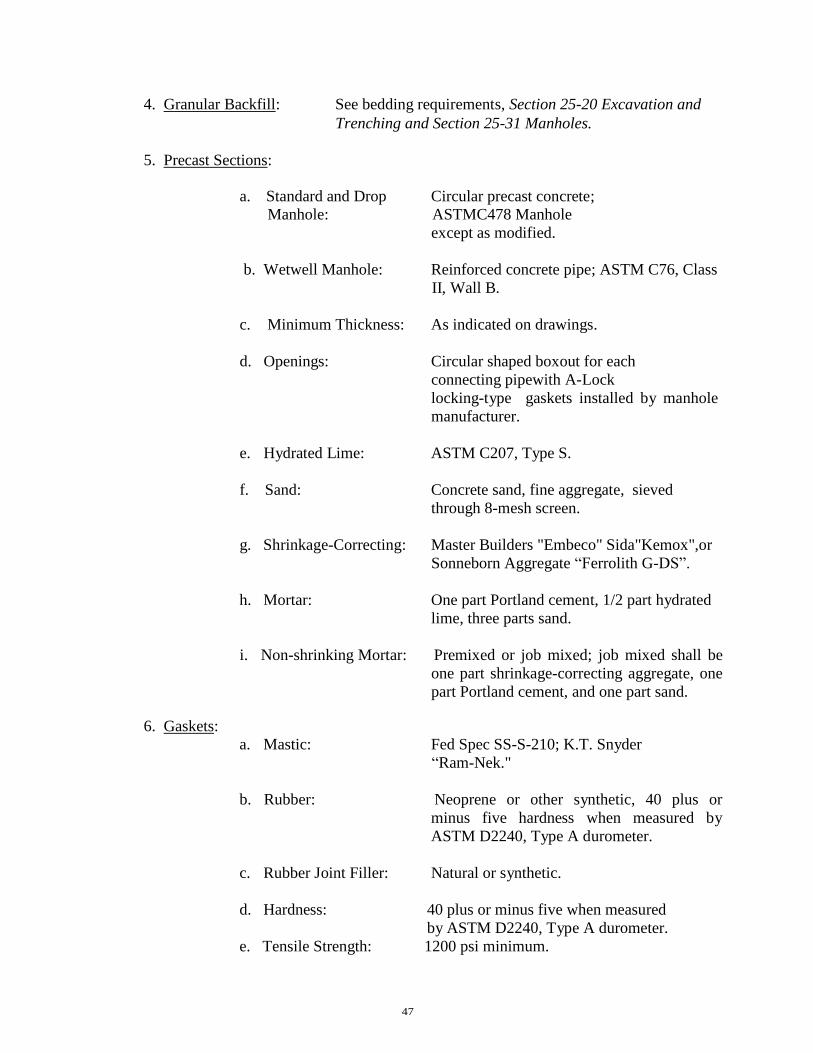
47
4. Granular Backfill: See bedding requirements, Section 25-20 Excavation and
Trenching and Section 25-31 Manholes.
5. Precast Sections:
a. Standard and Drop Circular precast concrete;
Manhole: ASTMC478 Manhole
except as modified.
b. Wetwell Manhole: Reinforced concrete pipe; ASTM C76, Class
II, Wall B.
c. Minimum Thickness: As indicated on drawings.
d. Openings: Circular shaped boxout for each
connecting pipewith A-Lock
locking-type gaskets installed by manhole
manufacturer.
e. Hydrated Lime: ASTM C207, Type S.
f. Sand: Concrete sand, fine aggregate, sieved
through 8-mesh screen.
g. Shrinkage-Correcting: Master Builders "Embeco" Sida"Kemox",or
Sonneborn Aggregate “Ferrolith G-DS”.
h. Mortar: One part Portland cement, 1/2 part hydrated
lime, three parts sand.
i. Non-shrinking Mortar: Premixed or job mixed; job mixed shall be
one part shrinkage-correcting aggregate, one
part Portland cement, and one part sand.
6. Gaskets:
a. Mastic: Fed Spec SS-S-210; K.T. Snyder
“Ram-Nek."
b. Rubber: Neoprene or other synthetic, 40 plus or
minus five hardness when measured by
ASTM D2240, Type A durometer.
c. Rubber Joint Filler: Natural or synthetic.
d. Hardness: 40 plus or minus five when measured
by ASTM D2240, Type A durometer.
e. Tensile Strength: 1200 psi minimum.

48
7. Manhole Steps:
a. Cast Iron: ASTM A48, with asphalt varnish
coating applied at the foundry.
b. Composition: Plastic ASTM 2146 Type II, Grade
16906. Steel reinforcing bar ASTM
A615.
c. Manhole Frame: ASTM A48, with coating applied at the
foundry. Frame and cover shall be equal to
a Neenah R-1642, Deeter 1247, or EJ 1045
Frame with 1040 AGS Cover imprinted with
“City of Nixa Sanitary Sewer”.
C. DELIVERY: Precast concrete sections shall not be delivered to the job until representative
concrete control cylinders have attained strength of at least 80 percent of the specified
minimum.
D. INSPECTION: Precast concrete sections and brick shall be inspected when delivered and
all cracked or otherwise visibly defective units rejected.
E. CONSTRUCTION: All mortar shall be used within 40 minutes after mixing. Mortar, which
has begun to take on initial set, shall be discarded and not mixed with additional cement
or new mortar. In no case shall the invert section through a manhole be greater than that
of the outgoing pipe. The shape of the invert shall conform exactly to the lower half of
the pipe it connects. Side branches shall be connected with as large radius of curve as
practicable. All inverts shall be troweled to a smooth clean surface.
Circular precast sections shall be provided with a rubber or mastic gasket to seal joints
between sections. The space between connecting pipes and the wall of precast sections
shall be equipped with A-Lock Locking-type gaskets or equal to be installed at the
factory.
F. WATERPROOFING: Manholes shall be waterproofed by application of heavy-duty coal tar
coating applied over entire exterior surface to attain a dry film thickness of not less than
15 mils. Surface to receive coating shall be thoroughly dry.
G. FRAMES AND COVERS: Frames shall be set so that the top of the cover is flush with
finished pavement or 2 inches higher than finish grade in unpaved areas except where
noted otherwise on the drawings. Watertight manhole covers shall be used wherever the
manhole tops may be flooded by street runoff or high water. Bolt-down cover assemblies
may be required on manholes subject to displacement by sewer surcharging. Locked
manhole covers may be desirable in isolated easement locations or where vandalism may
be a problem.

49
H. PIPE CONNECTIONS: Pipe connections shall be such that differential settlement between
pipe and manholes is permitted and shall be made using water stops, A-Lok gaskets,
standard O-ring gaskets, special manhole couplings, or other methods as approved.
I. STUBS: Future connections shall be provided in manholes at the locations shown on the
drawings. Stubs shall be not less than 3 feet and shall terminate in a bell plug. Final
length shall be determined by City for future anticipated connection.
J. HOLES: Core holes and handling holes shall be repaired by cementing a properly shaped
concrete plug in place with epoxy cement or by other methods acceptable to the
Engineer.
K. PAINTING: If castings arrive on the job without a foundry coating, one coat of coal tar paint
shall be applied. Before painting, all castings shall be thoroughly cleaned and properly
supported. All loose rust shall be removed by wire brushing. Castings shall not be
handled until the paint is dry and hard.
L. BENCH: A bench shall be provided on each side of any manhole channel when the pipe
diameter(s) are less than the manhole diameter. The bench should be sloped no less than
one-half inch per foot (0.50 in/ft). No pipe shall discharge onto the surface of the bench.
M. CORROSION PROTECTION FOR MANHOLES: Where corrosive conditions due to
septicity or other causes are anticipated, corrosion protection on the interior of the manholes
shall be provided.
N. STRUCTURES IN RELATION TO STREAMS: Manholes or other structures shall be
located so they do not interfere with the free discharge of flood flows of the stream.
O. MANHOLES IN RELATION TO WATER MAINS: Manholes shall be located at least ten
feet (10’) horizontally from any existing or proposed water main. Section 32. Sewer Acceptance Testing.
A. SCOPE: This section covers the performance testing of the installed sewer, force main, and
manholes.
B. GENERAL: The Contractor shall provide at his expense all necessary pumping equipment,
testing water, means of conveying test water to the testing site to include piping
connections between the piping and the nearest available source of test water, pressure
gauges, and other equipment, materials and facilities necessary for the tests.
All pipe, fittings, valves, pipe joints and other materials that are found to be defective
shall be removed immediately and replaced with new and acceptable material by and at
the expense of the Contractor.

50
C. SEWER PERFORMANCE TESTING: Each reach of sewer shall be performance tested. It
shall be the responsibility of the contractor to notify the City of Nixa personnel at least 24
hours in advance of the time and place at which testing work will be done. All defects
shall be repaired to the satisfaction of the Engineer and the City of Nixa. (#1578 4/09)
1. Lamping: Each straight section of sewer between manholes shall be straight and
uniformly graded. Each such section will be lamped by the Contractor in the presence
of the City Inspector. (#1578 4/09)
2. Exfiltration: The Contractor shall conduct an exfiltration test on each reach of sewer
between manholes. Exfiltration tests shall be conducted by blocking off all manhole
openings except those connecting with the reach being tested, filling the line and
measuring the water required to maintain a constant level in the manholes.
Each manhole shall be subjected to at least one exfiltration test. During the
exfiltration test, the water level shall be maintained at the top of the frame and cover
on each manhole to locate all leaks. Testing shall conform to the test procedures in
ASTM C969.
The total exfiltration shall not exceed 100 gallons per inch of nominal diameter per
mile of pipe per day for each reach tested. For purposes of determining maximum
allowable leakage, manholes shall be considered sections of 48 inch pipe. The
exfiltration tests shall be maintained on each reach for at least 2 hours and as much
longer as necessary, in the opinion of the City Inspector, to locate all leaks. (#1578
4/09)
The Contractor shall provide, at his own expense, all necessary piping between the
reach to be tested and the source of water supply, together with equipment and
materials required for the tests.
If the leakage in any reach exceeds the allowable minimum, it shall be re-tested after
the leaks are repaired.
In lieu of water testing of manholes, vacuum testing will be allowed. A vacuum of 5
psi for a period of 5 minutes is required or as much longer as necessary, in the
opinion of the City Inspector, to locate all leaks. (#1578 4/09)
Air testing will be in accordance with ASTM F1417-92 "Installation Acceptance of
Plastic Gravity Sewer Pipe Using Low Pressure Air.” A minimum pressure of 4 psi
for 4 minutes or longer, as necessary in the opinion of the City Inspector, shall be
maintained through each reach of sewer. (#1578 4/09)
3. Vacuum Test for Manhole: A vacuum test for manholes can be used in place of
exfiltration. Ten inches of mercury is needed for 2 minutes if the manhole is less than
10 feet deep. Ten inches of mercury for 2.5 minutes is needed if the manhole depth is
10 to 15 feet deep. Ten inches of mercury for 3 minutes is needed if the manhole

51
depth is from 15 to 25 feet deep. A loss of 1 inch of mercury per test is all that is
allowed. Testing shall conform to the test procedures in ASTM C1244 or the
manufacturer’s recommendations.
4. Infiltration: Infiltration shall also be tested by maintaining a minimum test pressure of
2 feet above the maximum groundwater elevation above the top of the pipe. If at any
time prior to the expiration of the guarantee period infiltration exceeds 100 gallons
per inch of nominal diameter per mile of sewer per day, the Contractor shall locate
the leaks and make repairs as necessary to control in the infiltration.
5. Vertical Deflection: Initial installed vertical deflection for flexible pipe (PVC sewer
pipe) shall not exceed 5 percent. The Contractor shall test the initial installed vertical
deflection by pulling a mandrel or other device through all reaches of sewer to
demonstrate that the 5 percent deflection limitation has not been exceeded. The deflection
testing shall not be performed until a minimum of 30 days after backfilling of pipe. The
method of test shall be acceptable to the Engineer and done in the presence of the City
Inspector. The City Inspector shall submit all deflection test results to the Engineer.
(#1578 4/09)
The rigid ball or mandrel used for the deflection test shall have a diameter not less than
ninety-five percent (95%) of the base inside diameter or average inside diameter of the
pipe depending on which is specified in the ASTM specification, including the appendix,
to which the pipe is manufactured. The test shall be performed without mechanical
pulling devices. A mandrel must have nine (9) or more odd number of flutes or points.
D. FORCE MAIN PERFORMANCE TESTING: The force main shall be subjected to
hydrostatic pressure testing and leakage testing as specified herein.
All testing work shall be done in the presence of the City Inspector. The Contractor shall
notify the City Inspector at least three days in advance of the times and places at which
testing work is to be done. (#1578 4/09)
1. Pressure Testing: The Contractor shall provide all necessary pumping equipment,
piping connections, pressure gauges, anchored or blocked test plugs, and all other
equipment, materials, and facilities necessary for the tests.
The test pressure at any point in the pipeline shall be equal to 100 psi. The test
pressure shall be maintained for at least 30 minutes and for whatever longer period is
necessary for the City Inspector to inspect the pipeline. (#1578 4/09)
All pipe, fittings, valves, pipe joints, and other materials that are found to be defective
shall be removed immediately and replaced with new and acceptable material, by and
at the expense of the Contractor. Following such replacement, the pressure test shall
be repeated. Such replacement of defective materials and re-testing shall continue
until the line and all parts thereof withstand the test pressure in a satisfactory manner.

52
2. Leakage Test: After the specified pressure test is completed and all pipeline repairs
have been made and retested to the satisfaction of the Engineer, the line being tested
shall be subjected to a leakage test. The hydrostatic pressure during leakage testing
may be any predetermined pressure selected by the Contractor, provided that it does
not exceed and is at least 75 percent of the pressure specified for pressure testing. The
selected pressure shall be maintained constant (within a maximum variation of plus or
minus 5 percent) during the entire time that line leakage measurements are being
made.
Leakage measurements shall not be started until a constant test pressure is
established; compression of air trapped in unvented pipes or fittings will give false
leakage readings under changing pressure conditions. After the selected test pressure
is stabilized, the line leakage shall be measured by means of a suitable water meter
installed in the pressure supply piping on the line side of the force pump. The water
meter shall be furnished and installed by the Contractor.
Line leakage shall be the total amount of water introduced into the line as measured
by the meter during the leakage test.
Each leakage test shall have a duration of 2 hours plus whatever additional period is
necessary to accurately determine leakage in the opinion of the Engineer.
The pipeline will not be accepted if the leakage indicated by the test is in excess of
that determined by the following formula:
where: Q = 0.015 DxLxN
Q = Allowable leakage in gallons per hour
D = Nominal diameter of pipe in inches
L = Length of section tested in thousand feet
N = Square root of average test pressure in psi
3. Defects: It is the intent of these specifications that all joints in piping shall be
watertight and free from visible leaks during the prescribed leakage test and each and
every leak which may be discovered at any time prior to the expiration of one year
from and after the date of final acceptance of the work by the City shall be located
and repaired by and at the expense of the Contractor, regardless of any amount that
the total line leakage rate during the specified leakage test may be below the specified
maximum rate.
The specified leakage test is to be made after the pipeline has been backfilled and the
joints covered. If such test shows a leakage rate in excess of the permissible
maximum, the Contractor shall make all necessary surveys in connection with the
location and repair of leaking joints to the extent required to reduce the total leakage
to an acceptable amount. Where evidence of leaking joints does not appear on the
ground surface above or near the leaks, the Contractor shall prospect the line by
sinking a hole, with an auger or otherwise, at the location of each joint and determine

53
any undue saturation of the soil which would indicate a leak at such joint; such
prospecting shall be done after pressure has been maintained in the line for a
sufficient time to provide adequate soil saturation for locating leaks by this method. Sections 33 thru 39 Reserved

54
ARTICLE III
CONCRETE AND GROUTING
Section 40. Portland Cement Concrete.
A. DESCRIPTION: The concrete described herein shall consist of a mixture of
Portland cement, fine aggregate, coarse aggregate, an air-entraining agent and
water combined in the proportions specified for the various classes of concrete
used in construction work and as set forth in these specifications.
B. MATERIALS: Cement shall be a standard brand Portland cement which shall
form to ASTM Designation C-150. Type 1 cement shall be used unless otherwise
provided in the special provisions.
Different brands or different types of cement from the same brand or type from
different mills shall not be mixed or used alternately in the same item of
construction unless authorized by the Engineer.
The Contractor shall not store cement at the site of the work without prior
approval from the Engineer.
The right is reserved by the City to sample the cement either at the origin of the
shipment or after delivery at the site of the work or the ready-mix concrete plant.
Professional acceptance by the City prior to completion of tests shall in no way
act as a waiver of the right to reject cement which has been shipped and not used
if, on completion of the tests, it fails to meet the requirements of the
specifications.
C. WATER: Water used with cement in concrete or mortar shall be clean, clear, free
from sugar and shall be free from injurious quantities of oil, acid, alkali, salt,
organic matter, vegetable matter or other deleterious substances.
D. FINE AGGREGATE: Fine aggregate shall consist of natural sand, manufactured
sand, or a combination thereof. The gradation requirements of fine aggregate shall
be as follows:
Passing 3/8 inch Sieve 100 percent
Passing No. 4 Sieve 95-100 percent
Passing No. 16 Sieve 40-80 percent
Passing No. 50 Sieve 5-30 percent
Passing No. 100 Sieve 0-10 percent
Fine aggregate shall conform to the requirements of ASTM Designation C-33 with

55
respect to deleterious substances, soundness and abrasion.
E. COURSE AGGREGATE: Coarse aggregates shall conform to the requirements of
ASTM Designation C-33 with respect to deleterious substances, soundness and
abrasion.
1. The coarse aggregate shall consist of a crushed stone or crushed gravel of
uniform quality. The gradation requirements of the coarse aggregate for Class
"A" concrete shall be as follows:
Passing 1 inch Sieve 100 percent
Passing No. 3/4 Sieve 90-100 percent
Passing No. 1/2 Sieve 40-60 percent
Passing No. 3/8 Sieve 10-30 percent
Passing No. 4 Sieve 0-5 percent
2. The gradation requirements of the Coarse aggregate for Class "X" concrete
shall be as follows:
Passing 1 inch Sieve 100 percent
Passing No. 1/2 Sieve 25-60 percent
Passing No. 4 Sieve 0-10 percent
Passing No. 8 Sieve 0-5 percent
F. AIR-ENTRAINMENT: The air-entrainment shall be obtained by the use of an
approved air-entrainment admixture conforming to ASTM Designation C260,
which shall be added during the process of mixing the concrete. Air-entrainment
Portland cement shall not be used. The admixture shall be dispensed by means of
a mechanically activated dispenser approved by the Engineer, except that in the
case of ready-mix concrete the flow may be started manually and the flow shall
shut off automatically when the required amount is delivered. The air-entraining
admixture shall be introduced into the stream of mixing water and the required
amount shall be fully discharged before all the mixing water has entered the drum.
The tank feeding the dispenser shall at all times contain an amount of air-
entraining admixture sufficient for the next batch and shall be provided with a
device approved by the Engineer for indicating visually when the supply runs
low. The amount of admixture to be used shall be less than 3 percent nor more
than 6 percent of the volume of the concrete.
G. FLY ASH: Fly Ash shall conform to ASTM Designation C-618.

56
H. PROPORTIONS OF MATERIALS: Class "A" concrete and Class "X" concrete
shall contain not less than 470 pounds of cement per cubic yard.
I. WATER CONTENT: The mixing water, including free surface moisture on the
aggregate, shall not exceed 6 gallons per sack of cement. The slump, when tested
in accordance with ASTM Designation C-143 shall be from 1 inch to 3 inches.
J. AIR CONTENT: Portland cement concrete shall have air-testing of not less than 3
percent nor more than 6 percent of the volume of the concrete when tested in
accordance with ASTM Designation C-173.
K. FLY ASH CONTENT: The Portland cement concrete shall contain not more than
100 pounds of fly ash per cubic yard.
L. MIX PROPORTIONS: In addition to the above requirements, the concrete materials
shall be proportioned so as to provide a uniform workable mix. Prior to the
beginning of construction, the Engineer may require the Contractor to furnish a
written statement giving the properties of the materials and the proportions by
weight (dry) of cement and of the fine and coarse aggregates that are proposed to
be used in each class of concrete.
M. GENERAL REQUIREMENTS: Concrete pouring operations shall be discontinued
when a descending ambient temperature away from artificial heat reaches 40
degrees Fahrenheit and not resumed until an ascending ambient temperature away
from artificial heat reaches 35 degrees Fahrenheit. If it is necessary for the
Contractor to take precautionary measures to prevent damage by freezing, such as
heating mixing water, heating aggregates or applying heat directly to the contents
of the mixer; aggregates shall not be heated higher than 150 degrees Fahrenheit,
when cement is added. The temperature of the mixed concrete when heating is
employed shall not be less than 30 degrees Fahrenheit and not more than 90
degrees Fahrenheit at the time of placement. Cement or fine aggregate containing
lumps or crusts of hardened material or frost shall not be used. Concrete shall not
be placed upon a frozen subgrade.
Ordinarily, the concrete shall be delivered to the job site in trucks so designed and
operated that the concrete will be thoroughly mixed during the time it is in transit
and shall be discharged at the site within a period of one and 1 1/2 hours after the
introduction of the mixing water. When concrete is placed at the job site, it shall
have the proper consistency and slump for satisfactory workability.
Testing shall be at the expense of the Contractor and shall consist of a slump test
performed on each batch of concrete delivered. The slump test will be made after
all on-site water has been added to the concrete prior to discharging. Three test
cylinders will be collected each day on random deliveries as directed by the
Engineer. Cylinders shall have a minimum 28-day compressive strength of 4,000
psi.

57
Section 41. Grouting.
A. SCOPE: This section covers grouting of pump, motor, and equipment baseplates or
bedplates; other miscellaneous baseplates; and other uses of grout as shown on the
drawings. All grouting shall be done with nonshrinking grout.
B. MATERIALS:
1. Nonshrinking: Grout Master Builders "Special LL-713 Grout", Sauereisen
Cements "F-100 Level Fill Grout", or U.S. Grout "Five Star
Grout".
2. Water: Clean and free from deleterious substances.
C. EXECUTION: Grout shall be furnished factory premixed so that only water is added
at the job site. Grout shall be mixed in a mechanical mixer. No more water shall
be used than is necessary to produce a flowable grout.
1. Preparation: The concrete foundation to receive grout shall be saturated with
water for 24 hours prior to grouting.
2. Placement Grout: Shall be placed in strict accordance with the directions of
the manufacturer so that all space beneath baseplates and bedplates is
completely filled without voids.
3. Edge Finishing: In all locations where the edge of the grout will be exposed to
view, the grout after it has reached its initial set shall be finished smooth.
Except where shown to be finished on a slope, the edges of grout shall be cut
off flush at the baseplate, bedplate, member, or piece of equipment.
4. Curing: Grout shall be protected against rapid loss of moisture by covering
with wet rags or polyethylene sheets. After edge finishing is completed, the
grout shall be wet cured for at least 7 days.
Sections 42 thru 49 Reserved

58
ARTICLE IV
STREETS
Section 50. Portland Cement Concrete Curb and Gutter .
(Also see Detail Drawings D1-AC, D1-CC and D-5 in the attached
Appendix.)
A. SCOPE OF WORK: The Contractor shall furnish all labor, materials, and equipment
to perform all operations in connection with construction of concrete curb and
gutter, in accordance with the City’s concrete specifications and drawings, and
subject to the terms and conditions of the contract.
B. MATERIALS: Class "A" Concrete shall be Portland Cement Concrete in accordance
with the City’s concrete specifications. Admixtures shall not be used unless
specifically approved by the Engineer.
Expansion joints shall be made with performed expansion joint filler of a non-
extruding type conforming to ASTM Designation D1751, configuration of the
curb and gutter as indicated in the Appendix.
Joint sealing compound for contraction joints shall be CRS-2 Asphalt Emulsion
meeting the requirements of ASTM Designation D3405. Curing compound shall
be a white pigmented membrane-forming liquid conforming to the requirements
of ASTM Designation C309, Type 2.
C. FORMS: Forms shall be made of metal and shall have a depth equal to or greater
than the prescribed edge of the thickness of pavement slab. The minimum length
of each section of form used shall be 10 feet. Each section or form shall be
uniform and free from undesirable bends or warps.
The maximum deviation of the top surface of any section shall not exceed 1/8
inch, or the inside face not more than 1/4 inch from planned alignment. The
method of connection between sections shall be such that the joint thus formed
shall be free from movement in any direction. Forms shall be of such cross-
section and strength and so secured as to resist the pressure of the impact and
vibration of any equipment which they support, without springing or settlement.
Every 10 foot length of form shall have at least three form braces and pin sockets
which shall be spaced at intervals of not more than 5 feet, having the end brace
and socket not more than 6 inches from the end of the form. Approved flexible
forms shall be used for construction where the radius is 150 feet or less.
The subgrade under the forms shall be compacted as specified herewith and cut to

59
grade so that the form when set will be uniformly supported for its entire length at
the specified elevation. Forms shall be joined neatly and in such a manner that the
joints are free from play or movement in any direction. The supply of forms shall
be sufficient to permit their remaining in place for at least 12 hours after the
concrete has been placed. All forms shall be cleaned and oiled prior to use.
The alignment and grade elevations of the forms shall be checked by the
Contractor, and the necessary corrections made immediately before placing the
concrete. When any form has been disturbed or any subgrade there under has
become unstable, the forms shall be reset and rechecked.
D. PLACING CONCRETE: The subgrade shall be moist but not muddy at the time of
placing concrete. If required by the Engineer, the prepared subgrade shall be
saturated with water the previous night, or not less than 6 hours or more than 20
hours prior to placing the concrete. If the sub grade subsequently becomes too
dry, it shall be sprinkled again ahead of placing concrete, in such a manner as not
to form mud or puddles of water.
The Contractor shall give the Engineer at least 8 hours advance notice before
placing concrete, and the subgrade shall be checked and approved by the Engineer
before any concrete is placed.
The concrete shall be mixed in quantities required for immediate use and shall be
deposited on the subgrade to the required depth and width of the curb and gutter
in successive batches and in a continuous operation without the use of
intermediate forms or bulkheads. The concrete shall be placed as uniformly as
possible in order to minimize the amount of additional spreading necessary. While
being placed, the concrete shall be vibrated with suitable tools so that the
formation of voids or honeycomb pockets is prevented.
The concrete shall be especially well-vibrated and tamped against the forms along
all joints. Care shall be taken in the distribution of the concrete to deposit a
sufficient volume along the outside form lines so that the curb section can be
consolidated and finished simultaneously with the slab.
No concrete shall be placed around manholes or other structures until they have
been adjusted to the required grade and alignment.
E. FINISHING: The curb shall be tooled to the required radii as soon as possible after
the concrete takes its initial set. The gutter shall be shaped with a wood float at
least 4 feet long. After the face forms and templates are removed, the joints shall
be tooled and the surface shall be final finished with a hard bristle broom to
remove all imperfections without additional mortar or dryer. In all cases, the
resulting surface shall be smooth and of uniform color, free from sags, twists or
warps and true to the specified lines and grades shown on the plans.

60
F. JOINTS: Expansion joints (formed with bituminous preformed expansion joints 3/4
inch thick or as specified on the plans and precut to exact cross section of curb)
shall be placed at all driveway radii and intersection radii and at intervals of not
more than 200 feet, and at the location shown on the plans or standard drawings,
so that they are not moved by depositing and compacting the concrete at these
joints. Preformed expansion joint filler shall be of non-extruding type and shall
conform to ASTM Designation D1781.
Contraction Joints shall be sawed or formed with templates at intervals between
not greater than 25 feet and at the location shown on the plans or standard
drawings and shall be sawed to a depth of 1 1/2 inches. Asphalt material used in
filling these joints shall be CRS-2 asphalt emulsion or as approved by the
Engineer. Contraction joints in proposed medians shall match the location of
joints in pavement. A template shall be 1/4 inch thick, cut to the configuration of
the curb section shown on the plans. Templates shall be secured so that they are
not moved by depositing and compacting the concrete.
Unless otherwise shown on the plans, and as soon as the concrete has hardened
sufficiently, the templates shall be rounded with an edging tool of 1/8 inch radius.
G. CURING: Immediately after the finishing operation has been completed and as soon
as marring of the concrete will not occur, the entire surface of the newly placed
concrete shall be sealed by spraying with a uniform application of white
pigmented membrane curing compound, at the rate of one gallon for each 150
square feet of surface. If rains fall on the newly coated surface before the film has
dried sufficiently to resist damage, or if the film is damaged in any other way, the
contractor will be required to apply additional curing material to the affected
portions.
H. COLD WEATHER PROTECTION: Cold weather protection shall be as specified in
Concrete General Requirements.
I. CURB AND GUTTER: Curb and gutter laid by slip-form or extruding equipment
will be accepted providing it complies with all of the above requirements other
than forms. The City retains the right to reject any slip-form equipment at its
discretion.
J. BACKFILLING: After curing, the curb shall be immediately backfilled to within
four (4) inches of the top curb to eliminate any possibility of washing beneath the
curb. The remaining four (4) inches shall be topsoil.
K. DRIVEWAY ENTRANCES: At all entrances, the concrete curb shall be removed
by saw cutting of either side of the entrance. After cutting, the exposed ends will
be rounded off by applying grout to provide a pleasing appearance. Removal of
curb by sledge hammer without first saw cutting shall not be allowed. All
replacement curbing and gutter pan shall be installed to provide positive drainage

61
as originally designed.
Section 51. Portland Cement, Concrete Pavement, and Integral Concrete Curb.
A. SCOPE OF WORK: Shall consist of furnishing all labor, materials, and equipment
necessary to perform all operations in connection with construction of Portland
Cement Concrete Pavement, in accordance with the specifications and drawings,
subject to the terms and conditions of the contract.
B. MATERIALS: Class "A" Concrete shall be Portland Cement Concrete in accordance
with Section 3A of these specifications. Reinforcing steel, if specified by the
plans, shall consist of deformed bars of grade 40 steel conforming to the
requirements of ASTM Designation A615 or of wire fabric conforming to ASTM
Designation A185.
Expansion joints shall be preformed expansion joint fillers of a non-extruding
type conforming to ASTM Designation D1751.
Joint sealing compound for sawed contraction joints and construction joints shall
be grade CRS-2 asphalt emulsion, or as approved by the Engineer.
Metal supports for tie bars or reinforcing bars shall be channel shaped pressed out
of 12-gauge sheet steel or heavier or as shown on the plans.
Dowel bars, where specified, for transverse joints shall be smooth, round bars of
the size specified. Burrs, mill scale and rust shall be removed. The free end shall
be painted with a suitable paint followed by a thin uniform coating of graphite
grease.
Expansion tubes or dowel caps shall be manufactured from 32 gauge sheet metal,
shall be indented to provide a limiting stop for the dowel bar, and shall provide
unobstructed expansion space of not less than one inch to permit movement of the
dowel bar. They shall be of proper size to fit the specified bars tightly, and the
closed end shall be watertight.
Curing compound shall be a white pigmented membrane-forming liquid,
conforming to the requirements of ASTM Designation C309, Type 2. 4B-3
C. FORM: Forms shall be made of metal and shall have a depth equal to or greater than
the prescribed edge thickness of the pavement slab. The minimum length of each
section of form used shall be 10 feet. Each section of form shall be uniform and
free from undesirable bends or warps.
The maximum deviation from planned grade of the top surface of any section
shall not exceed 1/8 inch, or the inside face not more than 1/4 inch from planned

62
alignment. The method of connection between sections shall be such that the joint
thus formed shall be free from movement in any direction. Forms shall be of such
cross-section and strength and so secured as to resist the pressure of the concrete
when planed, and the impact when planed, and the impact and vibration of any
equipment which they support, without springing or settlement.
Each 10 foot length of form shall have at least three form braces and pin sockets
which shall be spaced at intervals of not more than 5 feet, having the end brace
and socket not more than 6 inches from the end of the form. Approved flexible
forms shall be used for construction where radius is 150 feet or less.
The subgrade under the forms shall be compacted and cut to grade so that the
form when set will be uniformly supported for its entire length at the specified
elevation. Forms shall be joined neatly and in such a manner that the joints are
free from play or movement in any direction. The supply of forms shall be
sufficient to permit their remaining in place for at least 12 hours after the
concrete has been placed. All forms shall be cleaned and oiled prior to use.
The alignment and grade elevations of the forms shall be checked by the
Contractor and the necessary corrections made immediately before placing the
concrete. When any form has been disturbed or any subgrade thereunder has
become unstable, the form shall be reset and rechecked.
D. PLACING CONCRETE: Specifications here shall be identical to similar section
“Placing Concrete” above under section Portland Cement Concrete Curb and
Gutter.
E. CONSOLIDATING AND FINISHING: The pavement shall be struck off and
consolidated with a mechanical finishing machine or by hand-finishing methods.
When a mechanical finishing machine is used, the concrete shall be struck off at
such a height that after consolidated and finishing, it shall be at the elevations as
shown on the plans. A depth of excess concrete shall be carried in front of the
strike-off screed for the full width of the slab, whenever the screed is being used
to strike off the pavement. The finishing machine shall be provided with a screed
which will consolidate the concrete pressure. The concrete shall, through the use
of this machine, be brought to a true and even surface, free from rock pockets,
with the fewest possible number of passes of the machine. The edge of the screeds
along the curb line may be notched out to allow for sufficient concrete to form the
integral curb. Hand-finishing tools shall be kept available for use in case the
finishing machine breaks down.
When hand-finishing is used, the pavement shall be struck off and consolidated
by a vibrating screed or other approved equipment to the elevation shown on the
plans. When the forward motion of the vibrating screed is stopped, the vibrator
shall be shut off, and not be allowed to idle on the concrete. Internal mechanical
vibration shall be used along side all formed surfaces.

63
F. FLOATING, STRAIGHTENING AND EDGING: After the concrete has been struck
off and consolidated, it shall be further smoothed by means of a wood or
aluminum float at least 5 feet wide with a handle long enough to reach the entire
width of the slab being placed. The float shall be operated so as to remove any
excess water and laitance as well as surface irregularities. After the floating
operation, the pavement surface should be within the specified tolerances.
While the concrete is still plastic, the slab surface shall be tested for smoothness
with a 10 foot straightedge swung from handles 3 feet longer than one-half the
width of the slab. The straightedge shall be placed on the surface parallel to the
center line of the pavement and at not more than 5 foot intervals transversely.
After each test the straightedge shall be moved forward one-half of its length and
the operation repeated.
When irregularities are discovered, they shall be corrected by adding or removing
concrete. All disturbed places shall again be floated with the wooded float and
again straightedged. The pavement surface shall have no depression in which
water will stand.
Before final finishing is completed and before the concrete has taken its initial set,
the edges of the slab and curb shall be carefully finished with an edger of the
radius shown on the plans
G. FINAL SURFACE FINISH: A broom finish shall be used as the final finishing
method. A hard bristle broom shall be used which shall be kept clean and used in
such a manner as to provide a uniform textured surface. The curb shall have the
same final touch as the pavement.
The final surface of the concrete pavement and curb shall have a uniform gritty
texture that is free from excessive roughness and true to the grades and cross
section shown on the plans. The Engineer may require changes in the final
finishing procedure as required to produce the desired final surface texture.
H. JOINTS: Longitudinal and transverse joints shall be constructed as shown on the
plans or standard drawings.
Longitudinal joints are those joints parallel to the lane of construction. They may
be either center joints or the construction joints between construction lanes.
Traverse joints shall be contraction joints or contraction joints or construction
joints. Construction joints are put in transversely whenever construction
operations require them.
Expansion joints may be either longitudinal or transverse. They are used only
where specifically shown on the plans or standard drawings.

64
The edges of the pavement and those joints where such edging is shown on the
plans shall be rounded with an edger having a radius of not larger than 1/8 inch.
Transverse joints, except keyed and tied construction joints, shall be continuous
across the entire paved area including the curb.
I. TRANSVERSE JOINTS: Transverse joints shall be contraction, expansion or
construction joints. Contraction and expansion joints shall be placed as indicated
on the plans and construction joints wherever construction may require them.
They shall make a right angle with the center line of the pavement and with the
surface of the subgrade.
Expansion joints shall be installed in accordance with the size and locations
shown on the plans, and shall conform to the "Materials" requirements of these
specifications. They shall conform to the exact configuration of the curb section.
The filler shall be held accurately in place during the placing and finishing of the
concrete by means of a bulkhead, a metal channel cap or other approved methods.
Under no circumstances shall any concrete be left above or below the expansion
material or across the joint at any point. Any concrete, spanning the ends of the
joint next to the forms, shall be carefully cut away after the forms are removed.
Transverse contraction joints shall be of the sawed type, unless otherwise shown
on the plans. Care must be taken to saw the joints soon after concrete placement
to prevent contraction cracks. All transverse joints shall be sawed at least 1/4 of
the slab depth. Any procedure for sawing joints that results in premature and
uncontrolled cracking shall be revised immediately by adjusting the time interval
between the placing of the concrete and the cutting of the joint.
Transverse construction joints of the type shown on the plans or standard
drawings shall be placed wherever the placing of concrete is suspended for more
than 30 minutes. A butt type joint with dowels shall be used if the joint occurs at
the location of a contraction joint. Keyed joints with tie bars are used if the joint
occurs at any other location.
If joints are to be equipped with dowels, they shall be of the dimension and at the
spacing and location indicated on the plans. They shall be firmly supported in
place, and accurately aligned parallel to the pavement grade and the center line of
the pavement by means of a dowel support which will remain in the pavement and
will insure that the dowels are not displaced during construction. One-half of each
dowel shall be painted and greased and in an expansion joint, one end shall be
equipped with a tight fitting expansion tube of the dimensions shown on the plans
and conforming to the "Materials" requirements of these Specifications.

65
J. LONGITUDINAL JOINTS: Longitudinal joints shall be placed as shown on the plans
or standard drawings. They shall be of the sawed or the keyed construction type,
unless otherwise shown on the plans.
Sawed longitudinal center joints shall be sawed grooves made with a concrete saw
after the concrete hardened. The saw cut shall be at least 1/4 of the slab depth.
These joints are otherwise formed in the same manner as the transverse sawed
joints entitled "Transverse Contraction Joints."
Longitudinal keyed construction joints (i.e. joints between construction lanes)
shall be of the dimensions shown on the plans or standard drawings.
K. TIEBARS: Tiebars or tiebolts when shown on the plans or standard drawings shall
be of deformed steel and of the dimensions and at the spacing specified. Tiebars
shall be firmly supported by subgrade chairs or so installed as not to be displaced
during construction operation.
L. JOINT SEALER: After the curing period, all sawed and dummy groove joints in the
pavement shall be cleaned and sealed with material meeting the requirements
under "Materials" in this Specification. All foreign materials, joint sawing
residue, dirt and curing membrane shall be removed. Joints shall be lightly
underfilled (about 1/2 inch) to prevent extrusion of sealer. Any excess material
should be removed from the pavement surface as soon after sealing as possible.
M. STRUCTURES: All manholes, catch basins, or structures of a permanent nature
encountered in the area to be paved shall be raised or lowered as the case may be,
to the surface of the new pavement, and the necessary expansion joint material
placed around each structure for the full depth of the slab and of the thickness
shown on the plans or standard drawings.
N. CURING: Immediately after the finishing operation has been completed and as soon
as marring of the concrete would not occur, then entire surface of the newly
placed concrete shall be sealed by spraying it with a uniform application of white
pigmented membrane curing compound, at the rate of one gallon for each 150
square feet of surface. If rain falls on the newly coated surface before the film has
dried sufficiently to resist damage, or if the film is damaged in any other way, the
Contractor will be required to apply additional curing material to the affected
portions.
O. COLD WEATHER PROTECTION: Cold weather protection shall be provided as
necessary.
P. TOLERANCE IN PAVEMENT THICKNESS: It is the intent of these specifications
that pavement shall be constructed strictly in accordance with the thickness shown
on the plans. The thickness of the pavement will be measured, and where any
pavement is found deficient in thickness, in excess of one inch, it shall be

66
removed and replaced.
The thickness of the pavement will be determined by average caliper
measurement of cores. For the purpose of determining the construction thickness
of the pavement, 10 cores per mile will be taken at random intervals in each
traffic lane. In addition, cores may be taken at other locations as may be
determined by the Engineer. If the measurement of any core is deficient in excess
of 1 inch from the plan thickness, additional cores will be taken at 25-foot
intervals parallel to center line ahead and back of the affected location until the
extent of the deficiency has been determined
It will be assumed that each core is representative of the pavement thickness for a
distance extending one-half the distance to the next core, measured along center
line, or in the case of a beginning or ending core, the distance will extend to the
end of the pavement section.
The drilling of cores in irregular areas, or on projects involving less than 2500
square yards of concrete pavement, may be waived by the Engineer. In this case
the designed thickness will be considered as the measured thickness.
Q. PROTECTION AND OPENING TO TRAFFIC: The Contractor shall protect the
pavement against all damage prior to final acceptance of the work by the
Engineer. Traffic shall be excluded from the pavement by erecting and
maintaining barricades and signs for at least seven days.
R. PAVING BY SLIP FORM: Slip-forming equipment will be accepted providing it
produces a paving operation in compliance with all the foregoing requirements
other than forms.
S. INTEGRAL CURB: The work shall consist of furnishing all labor, materials, and
equipment necessary to construct integral curbs in accordance with the plans and
specifications. Integral curbs shall be required along the edges of all street
pavement as indicated on the plans, except at such locations as the Engineer may
direct. Depressed curbs shall be provided at all driveway entrances and sidewalks
shown on the plans.
T. MATERIALS: Class "A" concrete shall be Portland Cement Concrete in accordance
with these Specifications.
Expansion joints shall be preformed expansion joint fillers of a non-extruding
type conforming to ASTM Designation D1751.
Joint sealing compound for sawed contraction joints and construction joints shall
be grade CRS-2 emulsified asphalt, or as approved by the Engineer.

67
Liquid curing compound shall be a white pigmented membrane-forming liquid
conforming to the requirements of the ASTM Designation C309, Type 2.
U. CONSTRUCTION METHODS: The integral curb shall be constructed immediately
following the finishing operation unless otherwise shown on the plans. Special
care shall be taken so that the curb construction does not lag the pavement
construction and form a "Cold Joint".
Metal curb forms shall be required to form the backs of all curbs except where
street returns of small radius or other special sections make the use of steel forms
impractical.
The drilling of cores in irregular areas, or on projects involving less than 2500
square yards of concrete pavement, may be waived by the Engineer. In this case,
the designed thickness will be considered as the measured thickness.
V. PAVING BY SLIP FORM: Slip-forming equipment will be accepted, providing it
produces a paving operation in compliance with all the foregoing requirements
other than forms. In placing curb concrete, sufficient vibrating shall be done to
secure adequate bond with the paving slab and eliminate all voids in the curb.
Curbs shall be formed to the cross section as shown on the drawings with a mule
or templates supported on the side forms and with a wood float not less than four
feet in length.
The finished surface of the curb and gutter shall be checked by the use of the 10
foot straightedge and corrected if necessary. Where grades are flat and while
concrete is still plastic, the Engineer may require the Contractor to check the
drainage at the gutter by pouring water at the gutter summit and observing its flow
to the inlet. In order to prevent damage to the concrete surface, water should be
poured onto a piece of impervious paper or plastic.
In the construction of transverse joints of concrete integral curb pavement, special
care must be taken to see that all transverse joints extend continuously through the
pavement and curb.
Section 52. Plant Mix Bituminous Surface Course.
A. SCOPE OF WORK: The work shall include all labor, equipment, and materials
necessary for the furnishing, mixing, hauling, placing and consolidation of plant
mix bituminous surface course in accordance with the drawings and contract
documents.
B. MATERIALS: Asphalt cement for Surface Course shall meet, at minimum, PG grade
64-22, homogeneous and free from water, and shall not, on heating, foam below

68
the specified minimum flash point. It shall be prepared by refining crude
petroleum by suitable methods. It shall conform to all standard industry
requirements for the specified grade.
NOTE: The spot test shall be conducted in accordance with AASHTO T102, with
the following modifications: Add to Section 5.2.1, "If, however, the drop forms a
uniformly brown circular stain, the test shall be reported as negative. In case of
dispute, the entire test shall be repeated. "Delete Section 5.3 through 7.3,
inclusive."
C. COURSE OF AGGREGATE: All course aggregate shall consist of sound, durable
rock, free from cemented lumps or objectionable coatings. When tested in
accordance with AASHTO T96, the percentage of wear shall not exceed 50. The
percentage of delirious substances shall not exceed the following values and the
sum of percentages of all deleterious substances shall not exceed 8 percent.
Rock Type Percent by Weight
Deleterious Rock 8.0
Shale 1.0
Other foreign material 0.5
The requirements of this section apply to each size or fraction of aggregate
produced.
If a density requirement is specified for plant mix bituminous surface course the
total quantity of chert in each size or fraction of produced crushed stone
aggregate, including that permitted as deleterious, shall not vary more than 10
percentage points from the quantity present in the aggregates used in the approved
laboratory job mixtures.
D. FINE AGGREGATE: Fine aggregate for plant mix bituminous surface course shall
be a fine, granular material naturally produced by the disintegration of rock of a
siliceous nature. With written approval of the Engineer, chat sand produced from
flint chat in the Joplin area, or fines manufactured from crushed limestone,
igneous rock and chert gravel, or wet bottom boiler slag may be used as fine
aggregate for plant mix bituminous surface course. Fine aggregate shall be free
from cemented or conglomerated lumps and shall not have any coatings or
injurious material. The percentage of deleterious substances shall not exceed the
following values:
Item Percent by Weight
Clay lumps and shale 1.0
Total lightweight particles, including coal and lignite 0.5
Other deleterious substances 0.1

69
Lightweight sand particles are not considered deleterious lightweight particles.
The total lightweight particles requirement shall not apply to wet bottom boiler
slag, angular chert sand, or manufactured sand.
E. MINERAL FILLER: Mineral filler shall consist of limestone dust, Portland cement,
or other suitable mineral matter. It shall be thoroughly dry and free of lumps of
aggregations or fine particles. When tested in accordance with AASHTO T37 the
mineral filler shall conform to the following gradation requirements:
Sieve Size Passing Percent
Passing No. 30 sieve 100
Passing No. 50 sieve 95-100
Passing No. 100 sieve 90-100
Passing No. 200 sieve 70-100
The gradation of coarse aggregate shall be such that the total aggregate meets the
gradation requirements specified hereafter in Composition of Mixtures.”.
F. COMPOSITION OF MIXTURES: The total aggregate prior to mixing with asphalt
cement, shall meet the following requirements for Grade D mixture:
Grade D Gradation Percent by Weight
Passing 3/4 inch sieve 100
Passing 1/2 inch sieve 95-100
Passing No. 4 sieve 60-90
Passing No. 10 sieve 35-65
Passing No. 40 sieve 10-30
Passing No. 200 sieve 4-12
The combinations of materials as required in this section shall meet the gradation
requirements specified for the work.
Not less than 15 percent nor more than 30 percent natural siliceous sand, porphyry
sand, manufactured sand or flint sand of approved quality shall be added as a
separate ingredient. Sand shall have 100 percent passing the 3/8-inch sieve and
not more than 6 percent passing the No. 200 sieve.
The composition of the mixture shall conform to the following limits by weight:
Item Percent
Total Mineral Aggregate 92.0 - 96.5
Asphalt Cement 3.5 - 8.0

70
G. JOB-MIX FORMULA: Prior to preparing any mixture on the project, the Contractor
shall submit for the Engineer's approval, a job-mix formula for the mixture to be
supplied for the project. No mixture will be accepted for use until the job-mix
formula for the project is approved by the Engineer. The job-mix formula shall be
within the gradation range specified and shall include the type and sources of all
materials, the gradation of the aggregates, and the relative quantity of each
ingredient and shall state a definite percentage for each fraction of aggregate. No
job-mix formula will be approved which does not permit within the limits
specified in “Composition of Mixture“, the full tolerances specified in “Changes
in Proportion” for asphalt cement and not less than 1/2 the tolerances designated
for material passing the No. 10 sieve and the material passing the No. 200 sieve.
The job-mix formula approved for the mixture shall be in effect until modified in
writing by the Engineer. When unsatisfactory results or other conditions make it
necessary or should a source of material be changed, a new job-mix formula may
be required.
H. CHANGES IN PROPORTIONS: The Engineer will make such changes in the
proportions of asphalt cement and aggregates as he considers necessary within
the limits of the specifications. The proposed mixture will be compacted and
tested in a laboratory in accordance with AASHTO T167 and the bulk specific
gravity will be determined in accordance with the procedures described in
AASHTO T165.
The mixture of mineral aggregate and asphalt cement shall result in a bituminous
mixture which will be durable and retain satisfactory cohesion in the presence of
moisture. Chemical additions approved by the Engineer may be made to the
asphalt cement or to the mixture.
I. GRADATION CONTROL: In producing mixtures for the project, the plant shall be
so operated that no intentional deviations from the job-mix formula are made.
Mixtures as produced shall be subject to the following tolerances and controls.
Total aggregated gradation shall be within the master range specified in
“Composition of Mixtures” for Grade D mixture.
Maximum variation from the approved job-mix formula shall be within the
following tolerances:
Passing No. 10 sieve + 5.0 percentage points
Passing No. 200 sieve + 2.0 percentage points
Quality of Asphalt Cement introduced into the mixture shall be that quantity
specified in the job-mix formula. No change may be made in the quantity of
asphalt cement specified in the job-mix formula without written approval of the
Engineer. The quantity of asphalt cement determined by calculation or tests on the
final mixture shall not vary more than + 0.5 percentage points from the job-mix
71
formula.
J. COMMERCIAL MIXTURE: The Contractor may, at his option, use an approved
commercial mixture. The Contractor shall, at least 7 days prior to the desired time
of use, furnish a statement setting out the source and characteristics of the mixture
he proposes to furnish. The statement shall include: (1) the types and sources of
aggregates, percentage range of each, and range of combined gradation; (2) the
percent and grade of asphalt; and (3) the mixing time and range of mixture
temperature. The plant shall be designed and operated to produce a uniform,
thoroughly mixed material free from segregation. If the proposed mixture and
plant are approved by the Engineer, the component materials and the mixture
delivered will be accepted or rejected by visual inspection. The supplier shall
furnish with each truck load, a certification in triplicate that the materials and
mixture delivered are in conformance with his approved proposal. The mixture
shall be transported, placed and compacted as specified hereinafter.
K. WEATHER LIMITATIONS: Bituminous mixtures shall not be placed: (1) when
either the air temperature or the temperature of the surface on which the mixture
is to be placed is below 40 degrees Fahrenheit, (2) on any wet or frozen surface,
or (3) when weather conditions prevent the proper handling or finishing of the
mixture.
L. SUBGRADE PREPARATION: The subgrade upon which bituminous surface course
is to be placed shall be prepared in accordance with the requirements as shown on
the plans. If the bituminous surface course is to be placed upon the top of a
complete base course or existing hard surfaced pavement, then the base course or
existing pavement will be considered the subgrade for the next operation.
M. TACK COAT: The asphalt cement material used for tack coat shall be emulsified
asphalt meeting the requirements of AASHTO M140 or M208, and shall be Grade
SS-1 or SS-1H as designated by the Engineer.
N. PREPARATION OF SURFACE: The existing surface shall be free of all dust, loose
material, grease, or other foreign material at the time the tack is applied. Any fat
bituminous surface mixture or bituminous joint material will be removed by
others without cost to the Contractor before the tack is applied. The surface shall
be dry when the tack is applied, except in the case of emulsified asphalt. O. APPLICATIONS: Bituminous material shall be applied uniformly with a pressure
distributor at the rate specified in the contract, or as revised by the Engineer to be
within a minimum of 0.02 and a maximum of 0.10 gallon per square yard. In
using emulsified asphalt water may be added to the material and mixed therewith
in such proportion that the resulting mixture will contain not more than 50 percent
of added water, the exact quantity of added water to be specified by the Engineer.
The application of the resulting mixture shall be such that the original emulsion
will be spread at the specified rate. The tack material shall be heated at the time of
application to the temperature specified in the table below. The tack material shall

72
be properly cured and the tacked surface shall be cleaned of all dirt and surplus
sand before the next course is placed.
APPLICATION TEMPERATURES FOR BITUMINOUS MATERIALS
Temperature in Degrees Fahrenheit
Spraying Mixing Asphalt Emulsions
Bituminous Material Min. Max. Min. Max.
SS-1
75
130
75
130
SS-1H 75 130 75 130
The tack coat shall be applied in such manner as to cause the least inconvenience
to traffic. The tack may be applied full width, provided the tacked surface is
blotted with sand in such quantity as specified by the Engineer before it is opened
to traffic.
P. HAULING EQUIPMENT: Trucks used for hauling bituminous mixtures shall have
tight, clean, smooth, metal beds which have been thinly coated with a minimum
quantity of paraffin oil, lime solution, or other approved material to prevent the
mixture from adhering to the bed. Each load shall be covered with canvas or other
suitable material of sufficient size to protect the mixture from the weather. When
necessary, truck beds shall be insulated so that the mixture will be delivered on
the road to meet the requirements. No loads shall be sent out so late in the day that
spreading and compacting of the mixture cannot be completed during daylight.
Q. SPREADING: The base course, primed surface, or preceding course or layer shall be
cleaned of all dirt, packed soil, or any other foreign material prior to spreading the
bituminous mixture. When delivered to the roadbed, the mixture shall be at a
temperature which will permit proper placement and compaction. It shall be
spread with an approved spreading and finishing machine in the number of layers
and in the quantity required to obtain the compacted thickness and cross section
shown on the plans. The paver shall be operated at a speed that will give the best
results.
R. SURFACE CONDITION: The mixture shall be spread without tearing the surface
and struck off so that the surface is smooth and true to cross section, free from all
irregularities, and of uniform density throughout. Care shall be used in handling
the mixture to avoid segregation. Areas of segregated mixture shall be removed
and replaced with suitable mixture. The outside edges of the pavement shall be
constructed to an angle of approximately 45 degrees with the surface of the
roadbed. The outside edge alignment shall be uniform and any irregularities shall
be corrected by adding or removing mixture before compacting.
S. SPOT WEDGING AND LEVELING COURSE: Leveling course, consisting of a
layer of variable thickness used to eliminate irregularities in the existing surface,

73
shall be spread to the desired grade and cross section. Rigid control of the
placement thickness of the leveling course will be required. Spot wedging
operations over small areas, with featheredging at high points and ends of spot
areas, may be required prior to placing the leveling course. The use of an
approved finishing machine will be required on the spot wedging and leveling
course, except that the spreading of the spot wedging with a blade grader will be
permitted if results indicate the mixture is practically free from segregation.
T. JOINTS: Longitudinal and transverse joints shall be carefully made and well bonded.
Transverse joints shall be formed by cutting back on the previous run so as to
expose the full depth of the layer. A single lane of any layer shall not be
constructed to a length for which the adjacent lane cannot be completed in
succeeding operating day. The longitudinal joints in one layer shall offset those in
the layer immediately below by approximately 6 inches; however, the joints in the
final layer shall be at the lane lines of the travel way.
At locations designated in the contract or as specified by the Engineer, approaches
shall be tacked in accordance with “Tack Coat” and surfaced with a plant
bituminous mixture. The bituminous surface shall be placed in accordance with
the details shown on the typical section or as specified by the Engineer.
Approaches shall not be surfaced until after the surface course adjacent to the
entrance is completed. No direct payment will be made for any work required to
condition and prepare the subgrade on the approaches.
The mixture shall be thoroughly compacted by at least three complete coverages
over the entire area with either a pneumatic tire roller weighing not less than 10
tons, or a tandem-type steel wheel weighing not less than 10 tons. All rollers used
shall be in satisfactory condition, capable of reversing without backlash, and steel
wheel rollers shall be equipped with scrapers. Rollers shall have a system for
moistening each roll or wheel. Rolling shall begin as soon after spreading the
mixture as it will bear the weight of the roller without undue displacement. Final
rolling shall be done by the steel wheel roller. Rolling shall be performed at
proper time intervals and shall be continued until there is no visible evidence of
further consolidation and until all roller marks are eliminated.
The finished course shall have the nominal thickness shown on the plans and shall
be substantially free from waves or irregularities. The final riding surface, except
on medians and similar areas, shoulders, and temporary bypasses shall not vary
from a 10-foot straightedge, applied parallel to the center line, by more than 1/8
inch. At transverse construction joints, the surface of all other layers shall not
vary from the 10-foot straightedge by more than 1/4 inch. Surfaces exceeding
these tolerances shall be re-rolled, replaced, or otherwise corrected in a manner
satisfactory to the Engineer.
The surface of the mixture after compaction shall be smooth and true to the
established crown and grade. Any mixture showing an excess of asphalt cement

74
or that becomes loose and broken, mixed with dirt, or is in any way defective
shall be removed and replaced with satisfactory mixture, which shall be
immediately compacted to conform with the surrounding area.
It is the intent of these specifications that the plant mix bituminous surface course
shall be constructed strictly in accordance with the plant mix bituminous surface
course and the plant mix bituminous base course will be measured, and where the
total thickness is found to be deficient, corrective actions will be taken as
indicated hereinafter.
The total combined thickness of the bituminous surface course and the bituminous
base course will be measured and determined by average caliper measurement of
cores. For the purpose of determining the constructed thickness, 10 cores per mile
will be taken at random integrals in each traffic lane. In addition, cores may be
taken at other locations as may be determined by the Engineer. If the
measurements of any core is deficient in excess of 1/4 inch from the plan
thickness, additional cores will be taken at 25-foot intervals parallel to center line
ahead and back of the affected location until the extent of the deficiency has been
determined.
It will be assumed that each core is representative of the total combined thickness
for a distance extending one-half the distance to the next core, measured along
center line, or in the case of a beginning or ending core, the distance will extend
to the end of the pavement section.
The areas of deficiency shall be corrected by the addition of plant mix bituminous
surface course material and the areas shall be recompacted in accordance with
these specifications. The limits of the area of deficiency shall be defined as the
transverse distance from the outside edge of the pavement to the center line of the
street and a minimum longitudinal distance of 15 feet in both directions from the
deficient core. If the number of deficient pavement locations exceeds four per 1/4
mile or if the total area of deficient pavement sections exceed 5 percent of the
total pavement area in 1/4 mile, the Contractor shall be required to resurface the
entire 1/4 mile street surface area with a minimum thickness of 1/2 inch of plant
mix bituminous surface course. Additional test cores will be taken in order to
determine if the deficiencies have been corrected. The costs of all such additional
check cores will be at the Contractor's expense. The surface form which the cores
have been taken shall be restored by the Contractor within 48 hours using a
mixture acceptable to the Engineer.
Section 53. Plant Mix Bituminous Base Course.
A. SCOPE OF WORK: The work shall include all labor, equipment, and materials
necessary for the furnishing, mixing, hauling, placing and consolidation of plant
mix bituminous base course in accordance with the plans and contract documents.

75
B. MATERIALS: Asphalt cement for Base Course shall meet, at minimum, PG grade
64-22, homogeneous and free from water, and shall not, on heating, foam below
the specified minimum flash point. It shall be prepared by refining crude
petroleum by suitable methods. It shall conform to all standard industry
requirements.
C. FINE AGGREGATE: Fine aggregate for bituminous surface course shall be a fine,
granular material naturally produced by the disintegration of rock of a siliceous
nature. With written approval of the Engineer, chat sand produced from flint chat
in the Joplin area, or fines manufactured from crushed limestone, igneous rock
and chert gravel, or wet bottom boiler slag may be used as fine aggregate for plant
mix bituminous surface course. Fine aggregate shall be free from cemented or
conglomerated lumps and shall not have any coatings or injurious material. The
percentage of deleterious substances shall not exceed the following values:
Item Percent by Weight
Clay lumps and shale 1.0
Total lightweight particles, including coal and lignite 0.5
Other deleterious substances 0.1
Lightweight sand particles are not considered deleterious lightweight particles.
The total lightweight particles requirement shall not apply to wet bottom boiler
slag, angular chert sand, or manufactured sand.
D. MINERAL FILLER: Mineral filler shall consist of limestone dust, Portland cement,
or other suitable mineral matter. It shall be thoroughly dry and free of lumps of
aggregations of fine particles. When tested in accordance with AASHTO T37 the
mineral filler shall conform to the following gradation requirements:
Sieve Size Passing
Passing No. 30 sieve
Percent
100
Passing No. 50 sieve
Passing No. 100 sieve
Passing No. 200 sieve
95-100
90-100
70-100
E.
GRADED AGGREGATE:
Graded aggregate for bituminous base shall consist of
sound, durable rock particles, free from objectionable coatings. When tested in accordance with AASHTO T96, the percentage of wear shall not exceed 55. The
percentage of deleterious substances shall not exceed the following values and the
sum or percentages of all deleterious substances shall not exceed 8 percent.

76
Aggregate Type Percent Passing By Weight
Deleterious Rock 8.0
Mud Balls and Shale combined 2.0
Clay, uniformly dispersed 3.0
Other foreign material 0.5
The gradation of the course aggregate shall be such that the total aggregate meets
the gradation requirements specified hereafter under “Job Mix Formula, page 71,
prior to being fed into the cold aggregate feeders.
F. COMPOSITIONS OF MIXTURES: The bituminous base shall be composed of a
mixture of crushed limestone or dolomite, except as hereinafter permitted, filler if
needed, and asphalt cement. The aggregate prior to mixing with asphalt cement
shall meet the following gradation requirements:
Sieve Size Passing Percent by Weight
Passing 1 inch sieve 100
Passing 1/2 inch sieve 60-90
Passing No. 4 sieve 35-65
Passing No. 10 sieve 25-45
Passing No. 40 sieve 10-30
Passing No. 200 sieve 5-12
At the option of the Contractor, fine aggregate having 100 percent passing the
3/8-inch sieve and not more than 6 percent passing the No. 200 sieve may be
incorporated into the mixture. The total quantity of such fine aggregate shall not
exceed 30 percent by weight of the combined aggregate.
The composition of the mixture shall be as directed by the Engineer and shall
conform to the following limits by weight:
Item Percent
Total Mineral Aggregate 94-97
Asphalt Cement 3-6
G. JOB-MIX FORMULA: Prior to preparing any of the mixture on the project, the
contractor shall submit for the Engineer's approval, a job-mix formula for the
mixture to be supplied for the project. No mixture will be accepted for use until
the job-mix formula for the project is approved by the Engineer. The job-mix
formula shall be within the gradation range specified for bituminous base and
shall include the type and sources of all materials, the gradations of the aggregates
and the relative quantity of each ingredient, if more than one, and shall state a
definite percentage for each fraction of aggregate. No job-mix formula will be

77
approved, which does not permit within the limits specified in “Compositions of
Nature,” in the full tolerances specified in “Changes in Proportions,” and in the
full tolerances specified in “Gradation Control,” for material passing the No. 10
sieve and the material passing the No. 200 sieve. The job-mix formula approved
for the mixture shall be in effect until modified in writing by the Engineer. When
unsatisfactory results or other conditions make it necessary, or should a source of
material be changed, a new job-mix formula may be required.
H. CHANGES IN PROPORTIONS: The Engineer will make such changes in the
proportions of asphalt cement and aggregates as he considers necessary within the
limits of the specifications. The proposed mixture will be compacted and tested in
the laboratory in accordance with AASHTO T167 and the bulk specific gravity
will be determined in accordance with the procedures described in AASHTO
T165. The mixture of mineral aggregate and asphalt cement shall result in a
bituminous mixture which will be durable and retain satisfactory cohesion and
stability in the presence of moisture. Chemical additions approved in writing by
the Engineer may be made to the asphalt, cement, or to the mixture.
I. GRADATION CONTROL: In producing mixtures for the project, the plant shall be
so operated that no intentional deviations from the job-mix formula are made.
Mixtures as produced shall be subject to the following tolerances and controls.
Total aggregated gradation shall be within the master range specified in
“Composition of Natures” herein.
Maximum variation from the approved job-mix formula shall be within the
following tolerances:
Passing No. 10 sieve +/-5.0 percentage points
Passing No. 200 sieve +/-2.0 percentage points
J. QUALITY OF ASPHALT: Cement introduced into the mixture shall be that quantity
specified in the job-mix formula. No change may be made in the quantity of
asphalt cement specified in the job-mix formula without written approval of the
Engineer. The quantity of asphalt cement determined by calculation or tests on the
final mixture shall not vary more than +/-0.5 percentage points from the job-mix
formula.
K. COMMERCIAL MIXTURE: The Contractor may, at his option, use an approved
commercial mixture. The Contractor shall, at least 7 days prior to the desired time
of use, furnish a statement setting out the source and characteristics of the mixture
he proposes to furnish. The statement shall include: (1) the types and sources of
aggregates, percentage range of each, and range of combined gradation; (2) the
percent and grade of asphalt; and (3) the mixing time and range of mixture
temperature. The plant shall be designed and operated to produce a uniform,
thoroughly mixed material free from segregation. If the proposed mixture and

78
plant are approved by the Engineer, the component materials and the mixture
delivered will be accepted or rejected by visual inspection. The supplier shall
furnish with each truck load, a certification in triplicate that the materials and
mixture delivered are in conformance with his approved proposal. The mixture
shall be transported, placed and compacted as specified hereinafter.
L. WEATHER LIMITATIONS: Bituminous mixtures shall not be placed: (1) when
either the air temperature or the temperature of the surface on which the mixture
is to be placed is below 35 degrees F and, (2) on any wet or frozen surface, or (3)
when weather conditions prevent the proper handling or finishing of the mixture.
M. SUBGRADE PREPARATION: The subgrade shall be prepared in accordance with
the requirements “Subgrade Preparation” of these specifications.
N. PRIME COAT: The asphalt cement material used for prime coat on base rock shall
be Type MC, grade MC-30 and not be homogenous and be free from water, and
shall not, on heating, foam below the specified minimum flash point. It shall be
prepared by refining crude petroleum by suitable methods. It shall be prepared by
refining crude petroleum by suitable methods. It shall conform to all standard
industry requirements.
O. APPLICATION: Bituminous material shall be applied to the width of the section to
be primed by means of pressure distributor in a uniform, continuous spread. The
application rate shall be as specified in the contract or as revised by the Engineer
between 0.2 and 0.5 gallon per square yard. The primer shall be heated at the time
of application to a temperature specified in the following table.
P. PRIME COAT: The asphalt cement material used for prime coat on asphalt base
shall be Type SS-1, and not be homogenous and be free from water, and shall not,
on heating, foam below the specified minimum flash point. It shall be prepared by
refining crude petroleum by suitable methods. It shall conform to all standard
industry requirements.
Q. APPLICATION: Bituminous material shall be applied to the width of the section to
be primed by means of pressure distributor in a uniform, continuous spread. The
application rate shall be as specified in the contract or as revised by the Engineer
between 0.2 and 0.5 gallon per square yard. The primer shall be heated at the time
of application to a temperature specified in the following table.
APPLICATION TEMPERATURES FOR BITUMINOUS MATERIALS
Temperature, Degrees Fahrenheit
Bituminous Material Spraying Mixing
Min. Max. Min. Max.
Liquid Asphalt SS1 and MC Grade 150 50 110

79
Care shall be taken that the application of bituminous material at the junctions of
spreads is not in excess of the specified quantity. Building paper shall be placed
over the end of the previous applications and the joining application shall start on
the building paper. Building paper used shall be removed and satisfactorily
disposed. Pools of primer material remaining on the surface after the application
shall be removed.
When traffic is maintained, not more than one half of the width of the section
shall be treated in one application and one-way traffic will be permitted on the
untreated portion of the roadbed. As soon as the bituminous material has been
absorbed by the surface and will not pick up, traffic shall be routed to the treated
portion and the remaining width of the section shall be primed.
If, after the application of the prime coat, the bituminous material fails to
penetrate, and the roadbed must be used by traffic, sand blotter material shall be
spread in the quantity required to absorb any excess bituminous material. The
primer shall be properly cured, and the primed surface shall be cleaned of all dirt
and surplus sand before the next course is placed.
R. TRANSPORTATION: The prepared base course mixture shall be transported from
the paving plant to the work in tight vehicles previously cleaned of all foreign
materials. The inside of truck beds shall be lubricated with a thin oil to prevent the
mixture from adhering to the bed but an excess of lubricant will not be permitted.
Each load shall be covered with canvas or other suitable material of sufficient size
to protect it from the weather. No loads shall be sent out so late in the day that
spreading and compacting of the mixture cannot be done during daylight.
S. SPREADING: The base course, primed surface, or preceding course or layer shall be
cleaned of all dirt, packed soil, or any other foreign material prior to spreading the
bituminous mixture. When delivered to the roadbed, the mixture shall be at a
temperature which will permit proper placement and compaction. It shall be
spread with an approved spreading and finishing machine in the number of layers
and in the quantity required to obtain the compacted thickness and cross section
shown on the plans. The compacted thickness of a single layer shall not exceed 4
inches except the uppermost layer directly under the surface course for travel
ways and auxiliary lanes shall be placed in a single layer not to exceed the width
and thickness shown on the plans. In widening construction, the material may be
placed in two layers, provided the thickest layer is placed first and no individual
layer has a compacted thickness greater than 7 inches. On base widening work, a
succeeding layer of bituminous mixture may be placed the same day as the
previous layer, if it can be shown that the desired results are being obtained. On
small areas, and on areas which are inaccessible to mechanical spreading and
finishing equipment, the mixture may be spread and finished by hand methods if
permitted by the Engineer.

80
The mixture shall be spread without tearing the surface and struck off so that the
surface is smooth and true to cross section, free from all irregularities, and of
uniform density throughout. Care shall be used in handling the mixture to avoid
segregation. The outside edges of the base shall be constructed to an angle of
approximately 45 degrees with the surface of the roadbed. The outside edge
alignment shall be uniform and any irregularities shall be corrected by adding or
removing mixture before compacting.
If required by the contract, a leveling course consisting of a layer of variable
thickness shall be spread to the desired grade and cross section to eliminate
irregularities in the existing surface. Spot-leveling operations over small areas,
with featheredging at high points and ends of spot areas, may be required prior to
placing the leveling course. Rigid control of the placement thickness of the
leveling course will be required. The use of an approved finishing machine will be
required on the spot-leveling and the leveling course, except that the spreading of
the spot-leveling with a blade grader will be permitted if results indicate the
mixture is practically free from segregation.
T. JOINTS: Longitudinal and transverse joints shall be carefully made and well bonded.
Transverse joints shall be formed by cutting back on the previous run so as to
expose the full depth of the layer. The longitudinal joints in one layer shall offset
those in layers immediately below by approximately 6 inches.
U. COMPACTION: Rolling shall include the use of both a pneumatic tire roller and a
steel wheel roller. Rolling shall begin as soon after spreading the mixture as it will
bear the weight of the roller without undue displacement. All rollers shall be in
satisfactory condition capable of reversing without backlash, and steel wheel
rollers shall be equipped with scrapers. Rollers shall have a system for moistening
each roller wheel. A trench roller shall be used on depressed areas inaccessible to
regular width equipment. The compacted mixture shall have a density of not less
than 95 percent of that obtained by the laboratory compaction of a specimen made
in the proportions of the approved mixture. Density will be determined by the
direct transmission nuclear method or by a specific gravity method.
In lieu of roller and density requirements, mixtures used for shoulders adjacent to
rigid pavement, shoulders adjacent to resurfaced rigid pavement, temporary
bypasses to be maintained at the expense of the Contractor, and areas where a
commercial mixture is used shall be thoroughly compacted by at least three
complete coverage over the entire area with either a pneumatic tire roller
weighing not less than 10 tons, a tandem-type steel wheel roller weighing not less
than 10 tons, or an approved vibratory roller. Final rolling shall be done with the
tandem-type steel wheel roller. Rolling shall be performed at proper time intervals
on each layer and shall be continued until there is no visible evidence of further
consolidation.
V. SURFACE TOLERANCES: The finished layers shall be substantially free from

81
waves or irregularities and shall be true to the established crown and grade. At
transverse construction joints the surface of all layers shall not vary from a 10-
foot straight-edge, applied parallel to the centerline, by more than 1/4 inch, except
that the entire surface of the final layer of plant mix bituminous base mixture shall
not vary from the 10-foot straightedge by more than 1/8 inch if this layer is used
as the final riding surface course. Areas exceeding this tolerance shall be re-
rolled, replaced or otherwise corrected in a manner satisfactory to the Engineer.
W. TOLERANCE IN PAVEMENT THICKNESS: It is the intent of these specifications
that the plant mix bituminous base course shall be constructed strictly in
accordance with the thickness shown on the plans. The total thickness of the
pavement will be measured by coring as indicated under “Plant Mix Bituminous
Base Course”, Section 25-52. Where any pavement is found deficient in
thickness, corrective actions shall be taken as indicated under “Plant Mix
Bituminous Base Course”, Section 25-52.
No additional compensation will be allowed the Contractor for any plant mix
bituminous base course constructed in excess of the thickness requirements of the
plans and specifications. The surface from which the cores have been taken shall
be restored by the Contractor within 48 hours using a mixture acceptable to the
Engineer.
X. METHOD OF MEASUREMENT: Full depth pavement areas of plant mix
bituminous base course will be measured to the nearest 1/10 square yard. Areas
requiring a variable thickness bituminous base course will be measured on a per
ton basis. The weight of the bituminous base course for the areas requiring a
variable thickness will be determined from weight tickets for each truck
delivering base course to the job site. Final measurement for variable thickness
base course will be to the nearest 1/10 ton of acceptable base course.
Y. BASIS OF PAYMENT: Payment for all plant mix bituminous base course shall
include all labor, materials and equipment necessary for the construction of the
bituminous base course, in place. Prime coat will be considered incidental to said
construction unless specified separately in the specifications.
Payment for full depth pavement areas of plant mix bituminous base course will
be on a square yard basis. Payment for variable thickness bituminous base course
will be on a per ton basis. In case a truck load of bituminous base course is to be
spread in both areas of full depth pavement and variable depth pavement, the
Contractor and Engineer shall agree on the tonnage of that portion of the load
used in the variable depth area, prior to its placement. The conversion from tons
to square yards is based on 110 lb./sq. yd/inch.

82
Section 54. Aggregate for Base (Rock Base Course).
A. SCOPE OF WORK: The work shall include all labor, equipment, and materials
necessary for the furnishing, mixing, hauling and placing aggregate base course
(rock base) in accordance with the plans and contract documents.
B. TYPE 1 AGGREGATE: Type 1 aggregate for base shall be essentially limestone or
dolomite. It shall not contain more than 15 percent deleterious rock and shale.
Sand may be added only for the purpose of reducing the plasticity index of the
fraction passing the No. 40 sieve in the finished product. Any sand, silt and clay,
and any deleterious rock and shale shall be uniformly distributed throughout the
mass. The aggregates shall conform to the following gradation requirements:
SIEVE SIZE PERCENT
Passing 1-inch sieve 100
Passing 1/2-inch sieve 60-90
Passing No. 4 sieve 40-60
Passing No. 40 sieve 15-35
The fraction passing the No. 40 sieve shall have a plasticity index not to exceed
six.
C. PLACEMENT AND COMPACTION: Shall be well drained and compaction of
earthwork below street, sidewalk and driveway approaches by rolling, tamping or
any combination of these methods to meet minimum 95% compaction. (reference
MoDOT standards and specifications section 209).
D. SURFACE TOLERANCES: The finished layers shall be substantially free from
waves or irregularities and shall be true to the established crown and grade. At
transverse construction joints the surface of all layers shall not vary from a 10-
foot straight-edge, applied parallel to the centerline, by more than 1/4 inch. Areas
exceeding this tolerance shall be re-rolled, replaced or otherwise corrected in a
manner satisfactory to the City or Engineer.
E. TESTING SAMPLES: All samples collected for testing purposes shall be obtained
in the presence of an authorized City of Nixa employee. Any samples tested that
have not been obtained in the presence of an appointed City of Nixa employee
shall be considered invalid. All costs associated with testing shall be borne by the
contractor. The City of Nixa reserves the right to request testing at its discretion
(3/9/98).

83
Section 55. Sub Grade Preparations.
A. SCOPE OF WORK: The work shall include all labor, equipment, and materials
necessary for the furnishing, mixing, hauling and placing sub grade in accordance
with the plans and contract documents.
B. PLACEMENT AND COMPACTION: Sub grade shall consist of the compaction of
earth below the rock base for street, sidewalk and driveway approaches by rolling,
tamping or any combination of these methods to meet minimum 98% compaction.
(reference MoDOT standards and specifications).
C. SURFACE TOLERANCES: The finished layers shall be substantially free from
waves or irregularities and shall be true to the established crown and grade. Areas
exceeding this shall be re-rolled, replaced or otherwise corrected in a manner
satisfactory to the City or Engineer.
D. TESTING SAMPLES: All samples collected for testing purposes shall be obtained
in the presence of an authorized City of Nixa employee. Any samples tested that
have not been obtained in the presence of an appointed City of Nixa employee
shall be considered invalid. All costs associated with testing shall be borne by the
contractor. The City of Nixa reserves the right to request testing at its discretion
as specified above.
Section 56. General Notes. A. Expansion joints shall be placed on concrete curb & gutter at all driveway radii and
intersection radii and at intervals of not more than two hundred (200) feet.
Preformed expansion joint filler shall be of non-extruding type and shall conform
to ASTM Designation D1751. (See Detailed Drawing D-9 in the City of Nixa
Technical Specifications Book) B. Contraction joints shall be placed on concrete curb and gutter at intervals not greater
than twenty-five feet. Joints shall be filled with asphalt material. (See Detailed
Drawing D-9 in the City of Nixa Technical Specifications Book) C. Where concrete curbs must be removed to facilitate drive entrances, curbs must be
cut out prior to removal and the cut ends grouted to provide a pleasing
appearance.
Expansion joints shall be placed on concrete pavements as shown on the City of
Nixa standard joint location plan sheet for concrete pavements and concrete
pavement with integral curb. Expansion joints shall be located on straight runs at
intervals not exceeding 50 feet. Preformed expansion joint filler shall be of non-
extruding type and shall conform to ASTM Designation D1751.

84
D. Contraction joints shall be placed on concrete pavement as shown on the City of
Nixa standard joint location plan sheet for concrete pavements and concrete
pavement with integral curb.
Section 57. Design Standards for Streets and Roadways.
A. GRADES:
All street grades shall comply with the following minimum and maximum.
CLASSIFICATION MINIMUM MAXIMUM*
Alleys 0.5% 12%*
Local 0.5% 12%*
Collector 0.5% 10%*
Arterials 0.5% 8%
Parkways 0.5% 8%
* These are maximum allowable under any circumstance. The City reserves the
right to modify standards for all grades over 8%. All grades grater than 8% are
subject to review by the City and the Engineer and may require special
construction standards including additional subgrade, base and pavement
thickness and specifications. Additional requirements to meet this section will be
the responsibility of the developer/owner.
B. VERTICAL CURVES:
The length of vertical curves shall be no less than that determined by the formula:
L = KA, where
L = Length of vertical curve, feet,
A = Algebraic difference in grades
K = Constant defined in the following table.
CLASSIFICATION
K VALUES
CREST
SAG
Alleys 10 20
Local 20 30
Collector 40 50
Arterials 80 70
Parkways 80 70

85
C. HORIZONTAL CURVES AND SUPER ELEVATION:
The minimum centerline radii (R), maximum super elevation (E) and super
elevation runout length (L) shall be in accordance with the following table.
K VALUES
CLASSIFICATION R E L
Alleys 150 N/A N/A
Local 150 .02 80
Collector 250 .04 100
Arterials 500 .04 115
Parkways 500 .04 115
D. MINIMUM CURB RADII AT INTERSECTIONS:
INTERSECTING
CLASSIFICATION LOCAL & COLLECTOR
Alleys 15'
Local 15'
Collector 20’
Arterials 30'
Parkways 30'
E. INTERSECTIONS:
All curb returns shall be designed with a wheel chair ramp meeting the
requirements of Drawing D-10. No structures will be permitted in the ramp area.
Where the approach grade of either or both streets exceed four percent, a leveling
area shall be provided. The leveling area shall have a minimum length of 75 feet
measured from the intersection of the edge of gutter flag or edge of road within
which no grade shall exceed a maximum of three percent.
Right angle intersections shall be used whenever practical. The angle of
intersection shall not be less than 75 degrees.
F. PAVEMENT DESIGN:
Pavement sections shall be in accordance with the Drawing D-1. Soils
information and design calculations shall be submitted when deviating from the
standards shown on Drawing D-1.

86
Section 58. Street Permit and Inspections Required for all Street Cuts, Bores,
and Curb Cuts.
Street Permit shall be submitted and approved by the City before any street cut,
bore or curb cut begins. Street cuts within 4’ of final grade must be backfilled with Base
Rock, installed in 6” compacted lifts to within 8” of final grade. The final 8” shall be
filled with concrete. A City inspection of the rock fill is required before concrete is
placed. Street Cuts greater than 4’ shall be filled to within 4’ of final grade with ¾” clean
rock.
Sections 59 Reserved

87
ARTICLE V
EQUIPMENT
Section 60. Submersible Pump Station.
A. SCOPE: The pump station shall be furnished and installed complete as shown,
including wet well, wet well cover, pumps, controls, valves, valve box, slide rails,
supervisory system, high level alarms with lights and horn, security fencing, and
all equipment and appurtenances required to provide a complete and satisfactory
pumping installation. Potable water shall be extended to pump station location.
B. GENERAL: The complete pump station assembly including all equipment and
appurtenances shall be fabricated, assembled, erected and placed in proper
operating condition in full conformity with drawings, specifications, engineering
data, instructions, and recommendations of the sewage pumping station
manufacturer unless exceptions are noted by the Engineer.
The station shall be designated to withstand soil pressure based on a soil weight of
at least 120 pounds per cubic feet. All sizes, thickness, and deflection of the
component parts shall be acceptable to the Engineer.
C. WET WELL/VALVE BOX ACCESS: A wet well cover and valve box cover shall be
constructed of 1/4 " steel plate as shown. The wet well cover shall consist of a
double door access opening provided in the top to allow removal of either the
pump from the wet well or access to the float switch assembly. Each cover shall
be provided with a continuous hinge welded to a support frame. Each cover at the
wet well shall be reinforced to allow the total weight of a pump to be rested on it
during removal. Each cover at the wet well shall be reinforced with an angle
anchored to the circular wall to provide sufficient support if deemed necessary by
the Engineer.
D. SEWAGE PUMPING EQUIPMENT: The sewage pumping equipment to be
furnished and installed in the pumping station shall consist of motor driven,
nonclog sewage pumps, each complete with all specified accessories and
appurtenances.
Pumps shall be non-clog submersible pumps. All pumps in a station shall be the
same type. Each pumping unit shall conform to the following requirements:

88
1. Performance and Design Requirements:
Number of pumps and motors 2
Rated total head, feet As Required
Capacity at rated head, gpm As Required
Min. shutoff head, feet As Required
Min. total head for continuous operation, feet As Required
Max. bhp requirement of pump at any total head
in excess of min. head for continuous operation As Required
Operation speed, rpm As Required
Min. diameter of test sphere, inches. As Required
Min. suction inlet diameter, inches As Required
Min. discharge outlet diameter, inches As Required
Head losses through the pump, including pump suction elbow losses, are not
included in the total pumping heads stipulated in the foregoing design data
tabulation.
2. Pump Materials:
Item Material
Case Cast iron, ASTM A48
Impeller Cast iron, ASTM A48
Shaft Stainless steel or carbon steel w/ stainless
steel sleeve
Mechanical Seal Dura metallic "Dura Seal", double seal,
carbon and ceramic with No. 9 or better
carbon rings.
3. Non-Clog Submersible Pump Construction:
a. Motor - Pump motor shall be of the sealed submersible type rated as
necessary to meet the specified performance and design requirements.
Motors shall be for 240/480 volt, 60 Hz, 3 phase power supply. Stator
winding to be of the open type with insulation good for 80 degrees C.
Winding housing to be filled with a clean high dielectric oil that
lubricates bearings and seals and transfers heat from winding and rotor
to outer shell.
Motor shall have two heavy duty ball bearings to support pump shaft
and take radial and thrust loads and a sleeve guide bushing directly
above the lower seal to take radial load and act as flame path for seal
chamber. Ball bearings shall be designed for 30,000 hours B-10 life.
Stator shall be heat shrunk into motor housing.

89
A heat sensor thermostat shall be attached to and imbedded in the
winding and be connected in series with the motor starter contactor
coil to stop motor if temperature of winding is more than 220 degrees
F. Thermostat to reset automatically when motor cools to safe
operating temperature. Two heat sensors to be used on 3 phase motors.
The common pump motor shaft shall be of 416 stainless steel.
b. Seals - Motor shall be protected by two mechanical seals mounted in
tandem with a seal chamber between the seals. Seal chamber shall be
oil filled to lubricate seal face and to transmit heat from shaft to outer
shell. Seal face shall be carbon and ceramic and lapped to a flatness of
one light band.
A double electrode shall be mounted in the seal chamber to detect any
water entering the chamber through the lower seal. Water in the
chamber shall cause a red light to turn on at the control panel. This
signal shall not stop the motor but shall act as a warning only,
indicating service is required.
c. Impeller - Shall be cast iron and of the 2 vane non-clog enclosed type.
Vane inlet tips shall be carefully rounded to prevent stringy material
from catching in vanes. Pump-out vane shall be used in front and back
chamber and impeller shall be dynamically balanced by grinding on
shroud faces. No holes are to be drilled for balancing.
Impeller to be driven by stainless steel shaft key and impeller held in
place with lock screw and washer.
Impeller and motor shall lift off case as a unit without disturbing
discharge piping.
Impeller neck shall run in bronze wear ring that is pressed into volute
case.
d. Pump Case - The volute case shall be cast iron and have aflanged
center line discharge. Discharge flange shall be 4 inch standard with
bold holes straddling center line. Bronze wear ring to be pressed
into case for guiding impeller neck and to prevent corrosion freeze up.
Wear ring to be held from rotating by locking with stainless steel set
screw in end of ring.
e. Pump and Motor Casting - All castings shall be of high tensile cast
iron and shall be treated with phosphate and chromate rinse.

90
f. Bearing End Cap - Upper motor bearing cap shall be a separate casting
for easy mounting and replacement.
g. Power Cables - Power cord and control cord shall be double sealed.
The power and control conductor shall be single strand sealed with
epoxy potting compound and then clamped in place with rubber seal
bushing to seal outer jacket against leakage and to provide for strain
pull. Cords shall withstand a pull of 300 pounds to meet U.L.
requirements.
Insulation of power control cords shall be type SO or STOW. Both
control and power cords shall have a green carrier ground conductor
that attaches to motor frame.
E. DATA TO BE SUBMITTED: Each request from the Contractor for review of
equipment shall be accompanied by complete descriptive, performance and
engineering data covering equipment offered. Two copies of the following items
are required information.
Pump Data:
Name of Manufacturer,
Type and Model,
Design rotative speed,
Size of pump section inlet,
Size of suction elbow outlet,
Type and number of bearings,
Maximum bhp requirement of pump at any total head
specified minimum for continuous operation,
Maximum diameter of test sphere,
Complete performance curves showing capacity, head, &
NSPE requirements, efficiency and bhp requirements,
Shaft diameter,
Type of pump seal.
Motor Data:
Name of manufacturer
Type designation
Rated size of motor (hp), service factor, and temperature rating
Full load rotative speed
Weight
Input-Output efficiency at:
(a) Full Load
(b) Rated pump condition

91
Full Load current
Locked rotor current
Shaft diameter
Type of lubricant
Description of special moisture resistant treatment of motor air gap surfaces
F. SHOP TESTS: Each pump shall be shop tested for capacity, power requirement, and
efficiency at specified minimum head for continuous operation, rated head,
shutoff head, and at as many other points as necessary for accurate performance
curve plotting in each case. All tests shall be made in conformity with the
requirements and recommendations of the Hydraulic Institute. Shop tests shall be
conducted by the pump manufacturer or by the pumping station manufacturer
after installation in the pumping station.
Not less than two certified copies of a report covering each test, and capacity,
power, and efficiency curves based on shop test results shall be prepared and
delivered to the Engineer not less than 10 days prior to shipment of the equipment
from the factory.
G. RESPONSIBILITY: The manufacturer of the pumping station assembly shall be
responsible for proper installation, alignment, and operating conditions of the
pumping equipment when placed in service.
H. PUMPING STATION ELECTRICAL SYSTEM: The pumping station shall be
designed for 3 phase, 3 wire, 240 volt power service. Single phase, 120 volt
auxiliary power requirements and 24 volt control power requirements shall be
provided for by furnishing suitably sized dry type transformers within the station.
All wiring shall conform to the National Electrical Code and shall comply with
local regulations and ordinances of the community for which the station is
constructed.
1. Conduit: Except for plug-in cords and in control enclosures, all wiring shall be
in rigid galvanized steel or aluminum conduit or enclosed galvanized steel or
aluminum rectangular raceways. Conduit entering the wet well and control
panel shall be caulked to prevent the movement of gases from the wet well
into the control panel.
2. Cable: Except for continuation of exterior cables, cable and wiring shall be
factory installed. On stations where the disconnect shall employ more than
one breaker, breaker cable lugs shall be sized to fully accommodate both
service entrance conductors and branch service conductors. Removal of outer
strands of conductors to make up branch connections will not be permitted.
Where breaker lugs will not accommodate service, and branch conductors, T
type connectors or double lugs shall be provided. Thermoplastic insulated
neoprene covered service entrance conductors of the size required shall be
provided.

92
All power and control cable installed in the station shall be copper, insulated
for 600 volts, 75C, wet and dry locations, Underwriters Laboratories Type
RHH for power cable and Type RHH or THW for control cable. Bare copper
conductors shall be installed in all but lighting conduits for grounding
connections.
3. Equipment: All equipment and devices expressly intended as a means of
switching, adjusting, or actuating shall be mounted within convenient reach of
an attendant.
Externally operable circuit breaker type disconnect means shall permit
disconnecting all phase conductors in the station from service entrance
conductors.
Control and switching equipment enclosures shall be NEMA Type 3 finished
steel or rigid heavy-duty construction. Enclosures housing an assembly of
switches, contactors, relays, starters, etc., shall have hinged doors with
latches.
Each pump motor and auxiliary circuit shall be provided with thermal-
magnetic circuit breakers. Breakers for 3 phase loads shall be 3 pole. All
breakers shall be operable from outside the control panel. A three position
selector switch with HAND-OFF-AUTO position shall be flush mounted on
the panel door for operation of each pump motor. Auxiliary and control power
may be supplied through a circuit breaker load center.
All equipment shall be identified by nameplates and device identifications in
agreement
4. Panel Wiring: All control wiring in switching and control assemblies shall be
color coded or numbered. Color coding shall be such that electrically common
interconnections of devices are the same color. The colors may be used more
than once but not in the same circuit or cable grouping. Color of plug-in cord
conductors does not need to comply with the color code. The power and
control enclosure shall contain ground lugs or an AWG ground in the service
entrance circuit and each ground cable to devices in the station. The enclosure
shall be well grounded to the station shell by mounting or by an AWG band
jumper.
5. Controls: Wet well level and alarm controls shall be 120 volt and shall be
provided by sealed float type mercury switches. The mercury tube switches
shall be sealed in a solid polyurethane float for corrosion and shock resistance.
The support wire for each float switch shall have a heavy neoprene jacket. A
weight shall be attached to each support cord above the float to hold the
switch in place in the wet well. Weight shall be above the float to effectively
prevent sharp bends in the cord when the float operates. Each float switch

93
shall hang in the wet well supported only by the individual cord connected
thereto.
Three level sensors (normally open) and an electric alternator shall provide
automatic operation. The lower control shall be at the turn-off (STOP) level,
the upper control is to be set at the turn-on (START #1) level required and the
override control (START #2) is to be set above the upper control so both
pumps will come on if the level rises above the upper control. If one pump
fails for any reason, the other pump shall automatically operate on the
override control until cause of failure is corrected. A fourth level sensor
(normally open) shall operate a high level alarm and the supervisory system.
An automatic alternator with manual switch shall be provided to change the
sequence of operation at the end of each pumping cycle. The manual switch
shall allow for either pump to be selected as lead pump or for automatic
alteration.
An explosion proof junction box, suitable for a corrosive environment and
mounting outside the wet well, shall be furnished to connect the four control
cords to cables connecting the wet well controls to the pump station. This box
shall be constructed so incoming control wires are individually sealed with
mechanical rubber seal and so no sealing compounds are required to make
explosion-proof joints. Box shall be provided with terminal strip to connect
incoming wires with control cords. Control cords shall be sealed in box with
mechanical held rubber seal. Box cover shall be bolted on and sealed with
rubber "O" ring. Box and all connections shall be completely explosion-proof
and waterproof and shall not leak under an outside pressure of 10 psi. A
galvanized steel control cord support bracket shall be attached to the junction
box and the outside of the wet well top slab. Cord snubbers shall be furnished
to hold control cords at any set height.
6. Convenience Outlets: Convenience outlets for auxiliaries shall be 3 wire,
polarized grounded type, 15 amp, 125 volt. At least one similar duplex
convenience outlet shall be provided on a separate circuit for maintenance
tools.
7. Wiring Diagrams: The manufacturer shall provide both connection diagrams
and schematics, identifying all items in wiring connections in accordance with
terminal identification of equipment.
8. Supervisory: An audio/visual supervisory system shall be located at the pump
station to monitor the occurrence of a high wet well level situation. The
supervisory information shall be provided by normally open switches which
are wired into the control panel.
9. Elapsed Time Meters: An elapsed time meter capable of recording actual

94
running time shall be provided for each motor. Elapsed time meters shall be
mounted in the control panel of the pump station.
I. PIPING: Except where otherwise shown, all sewage piping shall be cast iron. Cast
iron pipe shall be ANSI Class 22 conforming to ANSI A21.6 or A21.8. Fittings
shall conform to ANSI A21.10. Mechanical joints shall conform to ANSI A21.11
and flanges shall be ANSI 125 lb. All pipe and fittings shall be coated inside and
out with the manufacturer's standard bituminous coating. Flange bolts and nuts
shall be ASTM A307, Grade B, of such length that, after installation, bolts will
project 1/8 to 3/8 inch beyond the outer face of the nut. Flange gaskets shall be of
ring type made from 1/11 inch thick red rubber or other approved material.
Flanged or mechanical joint pipe and fittings shall be used inside the pumping
station, and mechanical joint type bells shall be provided outside the station walls.
J. VALVES: Each pump discharge shall be provided with a check valve and an
eccentric plug valve. The check valves shall be located between the pumps and
the plug valve. In addition, the manufacturer shall provide auxiliary valve and
piping as shown on plans to a portable gasoline powered sewage pump.
1. Gate Valves: All 4 inch and larger gate valves shall conform to AWWA C500
as modified herein. Gate valves shall be double disc. AWWA gate valves shall
have O-ring stem seals.
2. Eccentric Plug Valves: Eccentric plug valves shall have a port area of at least
80 percent of the cross-section of the connecting piping and shall be
equivalent to DeZurik "Eccentric Valves". Eccentric plug valves shall be
installed with the shaft horizontal and the plug in the upper half of the body.
3. Check Valves: All check valves shall be flanged, iron body, horizontal swing
type with all seats, seat rings, pins, bushings and other parts subject to wear
constructed of bronze. Vertical check valves and straight globe check valves
will not be acceptable.
K. PAINTING AND CORROSION PROTECTION: Preparation of surfaces to be
painted and all painting shall be done in the shop before shipment of the station
assembly so that field painting will be limited to coating joints or areas not
previously painted, or damaged or abraded areas.
All pumps, motors, the control cabinet, explosion-proof junction box and controls
and other machines or equipment shall be painted in the shop using epoxy coating
or machinery enamel.
Exposed surfaces of copper tubing, including fittings, and valves, inside the
station shall have a natural finish obtained by cleaning and burnishing with "00"
steel wool and applying a coat of clear lacquer or shall be painted with epoxy.

95
All joints in wrought metal piping, including exposed threads, to be buried
underground, shall be painted with one heavy coat of Tnemec "Tnemecol 456",
Koppers "Bitumastic 50" or equal.
All painted surfaces damaged during shipment or installation shall be repainted
using the same or equivalent materials as used in the original application.
L. FACTORY TESTS: Before shipment from the factory, the pumping station shall be
operated to check alignment; faulty equipment and controls; proper wiring; leaks
in piping, seals, or welds; and proper operation of the automatic control system
and auxiliary equipment.
Pump suction and discharge lines shall be connected to a water tank and the
sewage pumps operated at least one hour to simulate the field service conditions.
The automatic control shall be adjusted to the specified levels. Defective
equipment and materials disclosed by such tests shall be replaced and the station
placed in satisfactory operating condition before shipment.
M. INSTALLATION OF PUMPING STATION: Backfill around structures shall be
placed as soon as the station installation is completed to the Engineer's
satisfaction. Backfilling shall be performed in accordance with the requirements
of “Structural Backfill” under “Excavation and Trenching.”
N. ACCESS ROAD: An access road shall be constructed from the nearest City street
to the lift station to provide access. Road shall be a minimum of fifteen feet wide
and shall meet all requirements for base rock, bituminous base and asphalt as
contained in these specifications. (See Detail Drawing D-1 in the City of Nixa
Technical Specifications Book)
O. SECURITY FENCING: Fencing shall be installed along the entire property line and
shall be constructed as approved on the design plans. Chain link or wood privacy
are most common and shall be 8’ in height. Gates shall be provided for access by
necessary equipment for future maintenance of the facility.
P. POTABLE WATER: A 1-inch PVC waterline shall be extended from the nearest
City water main to the pump station. A frost proof hydrant shall be installed at the
pump station for cleanup.
Q. GRADING: Maximum grading at the pump station shall be 3:1 for maintenance
purposes. Any grades exceeding 3:1 shall be poured concrete 4-inches in
thickness to a point where 3:1 slope can be achieved.

96
R. DRAWINGS AND DESCRIPTIVE DATA: Shop drawings shall be submitted
showing materials and assembly of all elements of the pump station. In addition to
pump and motor data to be submitted in paragraph "Data to be Submitted"
descriptive literature shall clearly indicate all information necessary to evaluate
conformance with specification requirements for all features of the pump station
including valves. Complete data for all electrical items, switches, enclosures,
relays, motor starters and controls, and a drawing of the control panel layout and a
schematic diagram of the control panel circuitry shall be included.
Section 61. Wet Well Mounted Pump Station.
Though some older Wet Well Mounted systems still exist on the system, no new
systems of this type shall be allowed.
Section 62. Standby Generator.
A. SCOPE: This section covers the furnishing and installation of a standby generator
system, complete including all material and control wiring, etc., required for a
complete installation.
B. GENERAL: The generator set shall be as specified herein; with dry-type transformer
and all accessories and transfer switches as required and shall be supplied by an
authorized distributor of the engine generator set manufacturer who warrants and
services the entire package, and having a service and parts organization within a
reasonable distance of this project, backed up by a national sales and service
organization.
The generator set shall be rated for continuous service at the required loading
80% power factor, 240/480 Volts AC, 3 Phase, at 60 Hertz, for operation at 38
degrees C ambient temperature, and 1500 meters altitude. Approved
manufacturers are Onan, Cummings and Caterpillar. Dry-type transformer and all
appurtenances shall be installed to carry required 120v systems installed with the
project during generator operations.
C. ENGINE: The engine shall be L.P. fueled, liquid-cooled and capable of satisfactory
performance operating on L.P. fuel. Engine speed shall be governed within 5
percent from no load to full rated output.
Engine shall be equipped with 12 Volt starting motor, battery charging alternator
with automatic regulator, 50 degree C (122 degree F) ambient radiator with fan
guards, engine coolant heater, 1500 watts minimum, thermostatically controlled to
maintain engine block coolant temperature between 120 and 140 degrees F.
D. ALTERNATOR: The alternator, having a single, maintenance free bearing, shall be

97
direct connected to the engine and shall be a broad range, 12 lead reconnectable,
four pole rotating field unit with rotating brushless exciter. It shall be self-
ventilated, with skewed stator and full amourtissuer windings with, 2/3 pitch for
smooth voltage wave form. Temperature rise shall be within NEMA MG1-22.40,
IEEE, and ANSI standards for standby duty at rated output. The balanced
telephone influence factor (TIF) shall not exceed 50. Insulation shall be within
class F with vacuum pressure impregnated epoxy on both rotor and stator.
The voltage regulator shall be of the static type and regulation shall be within plus
or minus two percent of rated voltage from no load to full load. The voltage
regulator shall include under frequency protection and moisture resistance
protection. On application of rated load at rated Power Factor, instantaneous
voltage dip shall not exceed 20% with recovery within one second.
E. FUEL TANK: The generator shall be equipped with a 250 gallon L.P. fuel tank. The
tank shall be equipped with level gauge. The tank shall be filled with L.P. as
recommended by the manufacturer.
F. CONTROLS: Set mounted controls shall include automatic start/stop control
operable by a remote contact with a switch to select off, automatic or test
(allowing set operation without interrupting the normal power supply) modes, a
voltage adjustment rheostat, automatic shutdown protection against high engine
coolant temperature, low engine oil pressure, engine cranking over 30-45 seconds,
and overspeed by directly cutting off the fuel supply, and a lamp to indicate an
engine failure has occurred.
G. INSTRUMENTS: The following engine and generator instruments will be set
mounted through vibration isolators in a NEMA 1 enclosure and fully wired with
appropriate reading lights: ENGINE: battery voltmeter, engine oil pressure and
coolant temperature gauges and running time hour-meter. GENERATOR: A.C.
voltmeter, A.C. ammeter, phase selector switch, and frequency meter.
H. MOUNTING: The electric plant shall be equipped with vibration isolators mounted
between the engine-generator and steel skid base.
I. ACCESSORIES: All accessories required for a complete operating system shall be
furnished. These shall include: one 12 volt lead acid battery sized per engine
manufacturers requirements, battery cables and rack, automatic float charger (5
amp minimum), residential muffler, stainless steel flexible exhaust connector, fuel
lines, 60 amp main line thermal magnetic circuit breaker, oil pan heater, and a
weather protective housing with removable side panels.
J. TRANSFER SWITCH: A manually operated transfer switch shall be provided by the
generator set manufacturer, rated at 400 amperes, 480 volts and 60 hz. The switch
shall have closing, withstanding and interrupting ratings equal to the available
short circuit current on the normal supply and shall be rated for continuous duty.

98
It shall be housed in a NEMA-1 enclosure suitable for wall mounting, shall
conform with Underwriters Laboratories 1008 Standards and all classes of load,
and meet the National Electric Code (NEC) requirements for critical applications.
The transfer mechanism shall be a circuit breaker type. Control circuitry shall be
solid state.
The transfer switch shall be equipped with; normal push buttons, transfer push
buttons, fixed 5 minute time delay for engine cool down, a test switch to simulate
a normal power source failure, pilot lights to visually indicate the transfer switch
position, and one set of normally open and normally closed contacts that indicate
switch position. The switch shall also be equipped with the following; volt, amp,
and frequency meters, 7-day exerciser clock for exercising with or without load.
K. TEST: Certified final factory test report shall be provided to the Engineer certifying
the units full power rating, voltage stability, and frequency regulation.
L. START-UP INSTRUCTIONS: A factory trained representative shall consult with the
contractor during installation and start-up. The representative shall fully instruct
the owners personnel as to correct operating and testing procedures and supply a
parts book and a complete operators manual for installation, operation and
maintenance.
M. WARRANTY: The generator set, transfer switch and accessories as furnished will
carry a one-year guarantee (two years if installed in the U.S. or Canada) against
defective parts and workmanship from the date of field testing and acceptance by
the first owner and shall include 100 percent parts and labor coverage.
Section 63. Lift Cranes.
A. PORTABLE CRANES:
1. General: Work under this section consists of furnishing and installing portable
hand winch operated crane and base for removal of the submersible pumps at
the pump station site.
2. Portable Crane: Portable cranes shall be geared hand winch operated, adjustable
boom type having a minimum lift capacity of 1,000 pounds. Boom shall be
easily detachable for moving. Mast height shall be a minimum of 61 inches
above base and boom shall be adjustable with a range of 41 to 65 inches of
reach and shall rotate a minimum of 240 degree. Winch shall be double geared
with automatic safety brake handle for safe positive to lower load. Portable
crane shall be Therm-o-matic Portacrane Model 533, Gilco Type Jt10 or
equal. Winch shall have a minimum of 30 feet of 1/2 inch lift cable.

99
Section 64. Mechanical and Plumbing. A. VALVES
1. General: All valves shall comply with the following:
a. Ends: All buried valves shall have push-on or mechanical joint ends
and conform to ANSI A21.11.
b. Rotation: The direction of rotation of the wrench nut to open shall be
to the left (counterclockwise). Each valve body or operator shall have
cast thereon the word OPEN and an arrow indicating the direction to
open.
c. Shop Painting: The interior and exterior of all valves shall be shop
painted for corrosion protection. The valve manufacturer's standard
paint will be acceptable.
B. GATE VALVES: Distribution valves in sizes through 12 inches shall be of the iron
body, non-rising bronze stem, resilient seated wedge type manufactured to
equal or exceed all applicable provisions of AWWA Standard C509. Gate
valves shall be wedge type epoxy coated 200 psi or approved equal to Mueller
Series A-2360.
C. FIRE HYDRANTS: Fire hydrants shall be 3-way, 6" mj shoe, 3'6" bury traffic model
with non-freezing, cast iron bodies, full bronze mounted, suitable for a working
pressure of 200 psi. Hydrants will be Mueller A-423, or approved equal.
All hydrants will be installed with a mechanical joint hydrant swivel tee and a
6"x13" swivel coupling for a complete restrained assembly from tee to hydrant.
No star bolts, dvc lugs, all thread rod, mega-lug or retainer glands will be
accepted.
D. VALVE BOXES: All gate valves in water lines shall be provided with valve boxes.
Valve boxes shall be a cast iron, extension sleeve type or Sch 40 PVC, suitable
for the depth of cover required by the drawings. Valve boxes shall not be less than
5 inches in diameter, shall have a minimum thickness at any point of 3/16 inch,
and shall be provided with suitable cast iron bases and covers.
E. FLANGED JOINTS: Whenever screwed-on flanges are used, the pipe shall extend
completely through the flange. The pipe end and flange face shall be finish
machined in a single operation. Flange faces shall be flat and perpendicular to the
pipe centerline.
When bolting flange joints, care shall be taken to insure that there is no restraint
on the opposite end of the pipe or fitting which would prevent uniform gasket

100
compression or which would cause unnecessary stress in the flanges. One flange
shall be free to move in any direction while the flange bolts are being tightened.
Bell and spigot joints shall not be packed or assembled until all flanged joints
affected thereby have been tightened. Bolts shall be tightened gradually and at a
uniform rate, so that gasket compression is uniform.
Special care shall be taken when connecting to pumping equipment to insure that
no stresses are transmitted to the pumping equipment to insure that no stresses are
transmitted to the pump flanges by the connected piping. All such piping shall be
permanently supported so that accurate matching of bolt holes and uniform
contact over the entire surface of abutting pump and piping flanges are obtained
before installation of any bolts in those flanges. In addition, pump connection
piping shall be free to move parallel to its longitudinal centerline while the bolts
are tightened.
F. CONNECTIONS WITH EXISTING PIPELINES: Where connections are made
between new work and existing piping, such connections shall be made using
suitable fittings for the conditions encountered. Each connection with an existing
pipe shall be made at a time and under conditions which will least interfere with
service to customers, and as authorized by the Owner. Live tapping will be
required. Facilities shall be provided for proper dewatering and for disposal of all
water removed from the dewatered lines without damage to adjacent property.
G. REACTION TO ANCHORAGE AND BLOCKING: All piping exposed in interior
locations and subject to internal pressure in which mechanical or similar type
joints are installed shall be blocked, anchored, or harnessed to preclude separation
of joints. All steel clamps, rods, bolts, and other metal accessories used in reaction
anchorages or joint harnesses shall be painted with two coats (in addition to a
prime coat) of a paint acceptable to the Engineer.
H. LEAKAGE: All joints shall be watertight and free from leaks. Each leak which is
discovered within one year after final acceptance of the work by the Owner shall
be repaired by and at the expense of the Contractor.
Section 65. Meter Services.
A. METER PITS AND COVERS: All 5/8 x 3/4 meters shall be housed in an 18"
diameter by 30" deep "White" PVC meter pit with a notched bottom for tube entry
into the pit.
Lids for meter pits shall be a cast iron, two piece raised similar to Crouch Foundry
Model C-104 or approved equal.
B. METER BRASS: All 5/8 x 3/4 meters shall be supplied with a brass service saddle
similar to a Ford S70 series or equal.

101
Service corporation stops shall be similar to Mueller H-15000 series or approved
equal.
Meter setters shall be a 5/8 x 3/4 x 7 setter similar to Mueller H-1404 and will
have a ball valve with lockwing. Yoke connectors will be Mueller 3/4 H-14227 or
similar.
Where meter services are split, all services shall be 1" from the service
corporation stop to a service wye similar to Ford Y44-243 or approved equal.
C. SERVICE TUBE: All service tubing shall be as follows:
All services shall be Type K copper tubing.
D. METERS: All meters when not supplied by the city shall be a 5/8 x 3/4 bronze disc
meter with cast iron freeze plate. Meters shall be equal to Badger M-25 and shall
meet the AWWA C-700 standard. All registers shall read in U.S. gallons.
Sections 66 thru 69 Reserved.

102
ARTICLE VI
ELECTRICAL
Section 70. Electrical General Requirements.
A. SCOPE: Electrical work includes complete Electrical systems as indicated in the
Contract Documents and shown on the contract drawings.
This Section generally describes these systems, but the scope of Electrical work
includes all such work indicated in all of the Contract Documents: Instructions to
Bidders; Bid Form; General Conditions; Supplementary Conditions; Drawings
and Specifications; and Addenda.
This Section requires the furnishing and installing a complete functioning system,
and each element thereof, as specified or indicated on the Drawings or reasonably
inferred; including every article, device, or accessory (whether or not specifically
called for by item) reasonably necessary to facilitate each system’s operation, as
indicated by the design and the equipment specified. Elements of the work
include materials, labor, supervision, supplies, equipment, transportation, and
utilities.
B. COORDINATION: The Contractor shall visit the site before submitting his bid and
shall verify all dimensions and locations before purchasing equipment or
commencing work.
The contractor shall maintain a foreman on the job whenever necessary to
coordinate his work with other Contractors and Subcontractors. He shall
cooperate with all Contractors to avoid interference or delay.
The contractor shall refer to the plans and to relevant equipment drawings and
shop drawings to determine the extent of clear spaces. He shall make all offsets
required to clear equipment, beams, and other structural members; and to
facilitate concealing conduit in the manner anticipated in the design.
C. MEASUREMENTS AND LAYOUTS: The Drawings are intended to cover the
layout and design of the work and are not to be scaled for exact measurements.
Where specific detail and dimension for Electrical work are not shown on the
Drawings, the General Contractor shall take measurements and make layouts as
required for the proper installation of the electrical work in coordination with all
other work on the project.
D. PERMITS AND LICENSES: All permits and licenses that are required by governing

103
authorities for the performance of electrical work shall be procured and paid for
by the General Contractor.
E. SHOP DRAWINGS AND MATERIAL LISTS: Contractor shall submit six copies of
his material list and of each shop drawing within thirty days after award of the
Contract. If any shop drawing cannot be obtained within thirty days, he shall
notify the Engineer immediately upon receiving notice of that fact.
Before submitting shop drawings and material lists, the Contractor shall verify
that all equipment submitted are mutually compatible and suitable for the
intended use. He shall verify that all equipment will fit the available space and
allow ample room for maintenance. If the size of equipment furnished makes
necessary any change in location, or configuration, the Contractor shall submit a
shop drawing showing the proposed layout.
All shop drawings prepared by manufacturers must be prechecked by Contractor;
must bear Contractor's stamp of approval and date; and must indicate a
specification paragraph under which submitted and the project’s name. Any
submittals not so identified will be returned to the Contractor without action.
The Engineer's checking and subsequent approval of such drawings, schedules,
literature, or illustrations shall not relieve the Contractor from responsibility for
deviations from Drawings or Specifications unless he has in writing, called the
Engineer's attention to such deviation at the time of submission, and secured
Engineer’s written approval. Nor shall it relieve him from responsibility for errors
in dimensions, details, size of members, or quantities, or omissions of components
or fittings; or for coordinating items with actual building conditions and adjacent
work.
Any corrections or modifications made by the Engineer shall be deemed
acceptable to the Contractor at no change in price unless written notice is
received by the Engineer prior to the performance of any work incorporating such
corrections or modifications.
Shop drawings shall be submitted for all major items of equipment and all articles
requiring coordination between Contractors. This shall include light fixtures,
panelboards, wiring devices, transformers, and special systems. Any shop
drawings being submitted shall be flagged and clouded where changed.
F. CODES, LAWS AND STANDARDS: Contractor's performance, workmanship, and
material shall comply with all governing codes, state statutes, city ordinances, and
regulations of regulatory bodies having jurisdiction.
Without limiting the generality of the foregoing paragraphs, the provisions of the
following National Fire Code shall be deemed applicable as Contractual
provisions: NFPA-70-National Electrical Code (current version adopted by City

104
of Nixa) is incorporated herein by references.
A reference to a NESC, NECA, NEMA, IEEE, ANSI, OR U.L. Standard shall
indicate that the article shall be the most currently adopted version of the article
and conform to that standard in all respects (including material, manufacturer,
handling, dimensions, and test procedure).
Contractor shall comply with rules and regulations of public utilities and
municipal departments affected by connections of service.
Laws, codes, ordinances and regulations shall take precedence excepting only
where work called for by the Drawings and Specifications exceeds code
requirements in quality and/or quantity.
All articles shall be listed or certified by a nationally recognized testing authority
(such as, but not limited to, Underwriters Laboratories or Factory Mutual
Engineering Corporation).
G. CLEANING: Dirt and refuse resulting from the performance of the work shall be
removed from the premises as required to prevent accumulation. The Electrical
Contractor shall cooperate in maintaining reasonably clean premises at all times.
Immediately prior to final inspection, the Contractor shall make a final cleanup of
dirt and refuse resulting from his work and shall assist in making the premises
broom clean.
Immediately prior to the final inspection, the Contractor shall clean all material
and equipment installed under the Electrical Contract. Dirt, dust, plaster, stains,
and foreign matter shall be removed from all surfaces. Damaged finishes shall be
touched up and restored to their original condition.
H. MATERIAL AND MANUFACTURER: All material and equipment shall be new,
shall be of the best quality and design, shall be free from defects and
imperfections, and shall have markings or nameplate identifying the manufacturer
and provide sufficient reference to establish quality, size, and capacity. All
material and equipment of the same type shall be made by the same manufacturer
whenever that is practicable.
I. LABOR AND WORKMANSHIP: All labor for the installation of material and
equipment furnished under the General Contract shall be done by experienced
mechanics of the proper trade. All workmanship shall be first class and in
compliance with the specific requirements of Drawings and Specifications.
J. CONTRACTOR’S EQUIPMENT: All hoists, scaffolds, staging, runways, tools,
machinery, and equipment required for the performance of the Electrical work
shall be furnished by the Electrical Contractor.

105
K. SAFETY REGULATIONS: All Electrical work shall be performed in compliance
with all applicable and governing safety regulations, including the National
Electric Safety Code (current addition) and OSHA regulations. All safety lights,
guards, and signs required for the performance of the electrical work shall be
provided and operated by the General Contractor.
L. STORAGE AND PROTECTION: Material and equipment shall be stored as
directed by the Engineer, maintained in a clean condition, and protected from
weather, moisture, and physical damage.
Material which becomes rusted or damaged shall be replaced or restored by the
Contractor to a condition acceptable to the Engineer.
M. ADJUSTING, ALIGNING, TESTING: All Electrical equipment on this project
furnished under this Division and all Electrical equipment furnished by others
shall be adjusted, aligned, and tested by the General Contractor.
Mechanisms of all Electrical equipment shall be checked, adjusted and tested for
proper operation. Motors shall be checked for alignment with drive and adjusted
as required. Protective devices and parts shall be checked and tested for specified
and required application and adjusted as required. Adjustable parts of all lighting
fixtures and Electrical equipment shall be checked, tested, and adjusted as
required to produce the intended performance.
Completed wiring systems shall be free from short circuits. After completion, the
Contractor shall perform tests for insulation resistance in accordance with the
requirements of the National Electrical Code.
The Contractor shall be held responsible for the operation, service, and
maintenance of all new Electrical equipment during construction and prior to
acceptance by the Owner of the completed project under this contract. All
Electrical equipment shall be maintained in the best operating condition,
including proper lubrication. Operational failure caused by defective material
and/or labor shall be immediately corrected and the Engineer shall be
immediately notified of any operation failure caused by defective material and/or
labor provided by others.
The Contractor shall maintain service and equipment for the testing of Electrical
equipment and apparatus until all work is approved and accepted by the Owner. A
first class voltmeter and ammeter shall be kept available at all times and the
Contractor shall provide service for test readings when and as required.
N. EXCAVATION AND BACKFILLING: Each Contractor shall perform all
excavation necessary for installation of work included in this section of the
specifications, regardless of character of material encountered. The contract price

106
will not be increased because of rock excavation, no matter what procedure is
utilized.
Each trench shall be uniformly graded and the bottom shall be free of soft spots
and stone. All water encountered in trenches must be drained away, or bailed and
pumped out, and the trench kept dry for the conduit laying. In no case shall
sewers be used as drains for such water. Trenches, close to walks or columns,
shall not be excavated without prior consultation with the Engineer.
For safety, the Contractor shall erect barricades around excavations; and shall
place an adequate number of amber lights on or near the work and shall keep
them burning from dusk to dawn. The Contractor shall be held responsible for any
damage that any parties may sustain in consequence of neglecting the necessary
precautions in prosecuting the work.
Each system shall be tested and accepted before backfilling. Backfill shall be in
layers not exceeding 12 inches. Fill shall be well tamped before additional
backfill material is placed. Backfill shall consist of earth or sand free of stone,
bricks, or foreign matter.
O. RECORD DRAWINGS: The Contractor shall show, on blue-line prints furnished
for that purpose, all changes from the original drawings made during the
installation of his work, and shall file them with the Engineer when the work is
completed.
P. NECA STANDARDS: The current NECA Standard of Installation, published by the
National Electrical Contractor's Association, incorporated herein by reference
shall be the minimum standard of performance on any matter not consistent with
express specifications.
Q. START UP OF SYSTEMS: Prior to start-up of Electrical systems, the Contractor
shall check all components and devices, lubricate items appropriately, and tighten
all screwed and bolted connections.
The Contractor shall review manufacturer's instructions on the proper procedure
for checking out each device and system, and shall follow those instructions.
After all systems have been inspected and adjusted, confirm all operating features
required by the specifications. Record and report malfunctions and then make
final adjustments. Operate all systems under full load.
R. OPERATING AND SERVICE MANUALS: At the completion of the project and at
least 14 days in advance of the request for final inspection, the Contractor shall
provide two volumes of manuals containing the following:
1. "Operating Instructions" for all major items of equipment, including start-up

107
and shut-down procedures.
2. "Service and Lubrication Instructions" for each unit of equipment, including
spare parts list indicating local source of supply.
Each complete set of manuals shall be bound in a three-ring, loose leaf, hard-back
binder.
S. TEMPORARY WIRING: The Contractor shall furnish and install 120/240 volt,
three-phase, four-wire, temporary power service and temporary lighting system
to facilitate construction.
The Contractor shall pay all charges made by the Electric utility, in respect to
energy charges.
The work by the Contractor shall consist of all labor, conduit, wiring, fuse blocks,
fused disconnecting switches, fuses, pigtails, receptacles, and other miscellaneous
materials required to complete the power system.
All temporary wiring shall be installed in accordance with applicable codes, and
shall be maintained in a safe manner.
When permanent wiring for lighting and power is installed, the Contractor may
use the permanent system, provided he assumes full responsibility for all
electrical material, equipment, and devices contained in the system.
When directed by the Engineer, all temporary service, wiring, and devices shall
be removed from the property by the Contractor.
Section 71. Underground Electric Service.
A. APPLICATION FOR SERVICE: Any person who desires to purchase electrical
energy from the City of Nixa shall make written application, signed by the
customer. All such applications shall contain a printed agreement stating that the
applicant will conform to and abide by all the rules, regulations and provisions of
the ordinances of the City pertaining to the regulation of electrical energy
customers.
B. INSPECTION: The application for a new service shall contain a description of the
premises to be served.
The Nixa Electric Department shall also have the right to inspect the installation
by the customer before electric service is provided.
C. CONSTRUCTION REQUIREMENTS: Construction of underground distribution

108
facilities must meet the requirements of the National Electrical Safety Code
(NESC) and the National Electric Code (NEC). The latest edition of all codes
shall apply.
The City of Nixa shall approve proposed contractors who will provide the
installation, together with evidence of insurance and financial capability of the
contractor. No work is to be performed by a contractor, if not so approved by the
City of Nixa.
D. SUBDIVISIONS: Cost and all materials for a complete electric system except
underground cable and transformers shall be supplied and installed by the
developer. Certain work will be completed and labor supplied by City of Nixa as
noted in the Technical Specifications. Said City provided labor shall be done
without expense to the developer.
At least 60 days prior to the time that the owner/developer desires approval, said
owner/developer shall file a complete set of plans, including a complete outline of
the equipment and material to be included, with the City of Nixa, demonstrating
the design of the intended electric installation.
Construction shall not commence without City of Nixa authorization.
The City of Nixa will bill the owner/developer $3.00 per lineal foot of
primary/secondary, served by the newly installed electric system. Billing for these
services will be due and payable prior to the Pre-Construction Meeting. Only after
installation, inspection and final acceptance by the City of Nixa, the City shall
supply power and operate the electric system. The City of Nixa will supply and
install all wire and transformers and bare the cost for same.
E. PROCEDURE: Upon approval of design plans by the City of Nixa, the City will
order appropriate wire and transformers. The developer’s contractor may begin
installation of conduits and systems based on the plans and Technical
Specifications. The developer is responsible to notify the Electric Superintendent
prior to burying any conduit for inspection. Once the installation of all conduits
and junction boxes is complete, the City will pull wire and set and tie-in
transformers.
F. UNDERGROUND PRIMARY SYSTEMS SPECIFICATIONS: The basic
underground distribution system within subdivision confines includes single
phase, 7200 volt; concentric neutral 15 KV cross-linked polyethylene insulated,
direct buried cable, installed in conduit with a normal minimal depth of forty-
eight inches below the final established grade line. Some three phase primary may
be required as part of the system by the City of Nixa when necessary for looping
and overall reliability of the distribution system. In some cases, certain switching
capabilities may also be required. Necessary three phase and switching
requirements may also part of the developers financial responsibility and will be

109
determined on a case by case basis. The distribution cables shall be terminated in
primary fused-switching pad mounted enclosures, junction boxes or in pad
mounted transformers.
All conduits are to be 2” diameter sch40 PVC electric conduit. All sweeps are to
be of same type and size and have a radius of 36” or 48”.
Junction boxes shall be Durham Steel/Fiberglass Junction Boxes or of equal
quality as approved by the Electric Superintendent and of sufficient size to
accommodate the specific application. Junction boxes shall be bedded with ½”
rock and shall be buried to within 6” from the top of the sleeve.
Secondary vaults shall be all fiberglass and bedded in ½”rock. The vault shall be
not more than 2” above ground level at finish grade. Transformer pads shall be
plastic type and bedded in ½” rock. Final lay shall be above finish grade level.
The single phase, 7200/120-240 volt transformer shall be the standard unit for
residential subdivision usage. The distribution cables shall be installed at the front
lot lines, wherever practical; the side lot lines when crossing from one block or
area to another; or the curb edge of the street for main line distribution runs to
enter or leave an area. The underground primary distribution system shall be of
the loop-fed type, capable of being separated at each transformer location by
means of loadbreak cable terminators.
G. UNDERGROUND SECONDARY SYSTEMS SPECIFICATIONS: The basic
underground secondary distribution system shall be of the 120-240 volt; single
phase; triplexed; cross-linked polyethylene, 600 volt type insulation; direct burial
cable type with pad mounted transformers to pedestal runs not smaller than #4/0
AWG (Al). The secondary distribution triplexed conductor shall terminate in a
connection box (pedestal) located at the back lot line area, where most convenient
to serve the largest group of houses. The secondary distribution cables shall be
run in a random lay method, wherever possible, and at a minimal depth of thirty-
two (32) inches below the final established grade line.
H. EASEMENTS: For locations being served by the underground electrical distribution
system, the owner or developer shall provide utility easements, at no cost for
electrical facilities to the City of Nixa. Easements for subdivisions shall be shown
and recorded on the subdivision plat map.
I. DEVELOPER OR BUILDER’S RESPONSIBILITY: The electric system shall be
designed as an underground distribution system, and the subdivider, builder, or
developer must present a construction schedule for the area so that the URD
systems can be installed in an orderly, logical method. All sewer and water main
installations and any other underground systems located deeper than the electrical
system shall be installed prior to installation of the URD system. The lots or
easements for underground electrical systems shall be graded to within 6 inches of

110
final grade; all lots and easements shall be staked with all stakes to be marked to
show lot numbers and final grades; and all obstructions including vegetation and
dirt piles shall be removed from the easements and R-O-W by the developer prior
to the installation of the electric system. The developer shall coordinate the
installation of the streets to properly install the URD system or install conduit
across the roads and streets after the street has been brought to sub-grade
elevation and prior to any further street construction in the area of the crossing. If
the installation of streets is not coordinated and the developer incurs extra expense
in installing crossings due to requirements for boring, tunneling, street repair, etc.,
such extra expenses shall be paid by the developer.
J. GRADES AND STAKING: It shall be the developer's responsibility to provide the
final grades; all staking for easements, road crossings and lots; and to coordinate
the installation of the underground facilities. If the grades, easement stakes, or
street crossings are wrong or are changed after the installation of the street
crossings or the URD system, the cost of moving or rebuilding the URD system
as a result of the error or change shall be paid for by the developer.
K. DAMAGE TO URD SYSTEMS AFTER INSTALLATION: It shall be the
responsibility of any contractors, excavators, developers, builders or any person
working in an area with underground electrical cables to determine the location of
same and take whatever precautions necessary to avoid damage to same. Any
damage to the system repair by the City of Nixa shall be billed at full cost to the
persons causing the damage.
L. DRAWINGS AND DESIGNS: It shall be the developer or customer's responsibility
to provide the City of Nixa with complete and accurate drawings and layouts for
new subdivisions, planned unit developments or any other project requiring the
installation of new electrical facilities. The drawings must be furnished far enough
in advance of construction so as to allow sufficient time for the review of the
facilities and the layout of easements. If the developer or customer should change
the plans or change the project at any time after the design has begun, the
developer shall pay the full expense incurred by the changes.
Section 72. Overhead Electric.
The complete overhead electric system, including all materials for a completed
system shall be furnished and installed by the City of Nixa. The City of Nixa will bill the
owner/developer $500.00 per lot, served by the newly installed electric system. Billing
for these services will be due and payable prior to the Pre-construction meeting; and the
City of Nixa shall thereafter operate and maintain the electric system.

111
Section 73. Metering.
A. GENERAL: The owner/developer shall be completely responsible for the furnishing
and installation of the metering service, including the required wire, conduit and
meter base(s). Metering equipment which will be provided by the City of Nixa
consists of the following items as are required for the particular installation: watt-
hour meters, demand registers, recording demand devices and instrument
transformers. The equipment supplied by the City of Nixa for a specific
installation will be dependent upon the billing requirements of the applicable rate
and the City of Nixa's standard practices.
B. SELF-CONTAINED INSTALLATION: If the voltage of the electricity to be
metered is 480 volts or less and the customer's disconnecting means has a rating
of 200 amperes or less, self-contained metering equipment shall be installed for
all new and revised installations.
The meter-switch-fuse sequence shall be followed where practical for all
installations where single phase or three phase, self-contained meters are used.
New or revised single phase or three phase installations shall be installed outside
of the building. However, if a large number of self-contained meters are involved,
or if for any other reason the Nixa Electrical Department determines that outdoor
metering is impractical or inadvisable, the metering equipment shall be installed
indoors.
Where two or more meters are installed within a building, the meter sockets shall
be banked on a panel in a location that will be accessible for meter reading, meter
testing or other maintenance and labeled, tagged or stenciled showing the
complete address and location of the area served such as apartment, office or store
in the building for which the metering equipment is being installed.
Multiple meter type services shall be reviewed with and approved by the Nixa
Electrical Department prior to ordering or installing equipment.
C. INSTRUMENTAL TRANSFORMER TYPE INSTALLATIONS: If the voltage of
the electricity to be metered is 480 volts or less and the customer's disconnecting
means has a rating in excess of 200 amperes, a current transformer metering
installation shall be installed for all new or revised installations.
The meter-switch-fuse sequence shall be followed where practical for all
installations where single phase or three phase, instrument transformer type
meters are used.
For single phase and three phase services requiring multiple metering, the details
of the service entrance and equipment must be reviewed and approved by the City
of Nixa prior to ordering or installing equipment. In all cases the current
transformers shall be provided by the City of Nixa in C.T. gear. The meters will

112
be furnished by the City of Nixa and may be mounted by the developer/owner on
the switchgear provided the meters are located 5 feet above the floor and that the
meters will be completely accessible at all times for meter reading, meter testing
and other maintenance. The meter socket, test switches, meter conductors and all
other equipment for the meter installation, except current transformers and meters,
shall be provided by the owner or customer and shall be pre-wired or assembled
by the owner or customer. For those cases when the above conditions cannot be
met, the owner or customer shall provide and install meter sockets equal to or
better than a Milbank S9319-XL or a Superior #W11523-M with a 1058-F 13
terminal prewired meter socket with color coded P.T. and C.T. switches. The
meter sockets will be located on an outside building wall, 5 feet above final grade
and in such a position that there will be no obstructions to meter reading, meter
testing or other maintenance. The owner or customer shall also provide and install
a 1 inch conduit from each meter socket to its respective current transformers. The
City of Nixa will provide and install the metering.
Services and metering installations for primary metering will be handled on an
individual basis. All service installations must be reviewed and approved by the
City of Nixa prior to ordering or installing equipment.
D. RESIDENTIAL SERVICES: The standard electric service to residential customers is
120/240 single phase 200 ampere service. All underground services shall be 2
inch schedule 40 pvc placed in the ditch 30 inches deep with glued joints and 36
inch sweep ells on all corners and up to pole and meter loop, 2/o aluminum wire
on services up to 150 amp and 4/o wire on 200 amp service is required. A
distance of 35 feet of wire coiled up should be left at the bottom of the pole and
also 2 feet of wire should be extended out from the meter base. House numbers
must be stamped on the meter base if more than one meter appears at that
location. The house number must be on the house before the electric service will
be hooked up. For the purpose of installing the electric service conductors,
residential customers include single family dwellings, townhouses and duplexes.
Multiple occupancy buildings and other than those stated will be treated as
commercial customers for the purpose of installing the service conductors. All
standard electric services to residential customers will be provided by the
owner/developer at no cost to the City of Nixa. One electric service will be
provided to each residential premise, and not more than one. All services other
than 200 amp 120-240 volt services shall be considered non-standard and will be
installed only with special permission of the City of Nixa after reviewing all
circumstances. The excess cost will be paid by the customer (owner/developer),
prior to installation of the facilities.
E. UNDERGROUND SERVICES: Underground services shall be delivered to
residences by means of buried triplex cable from a pedestal or pad mounted
transformer located on the property line to a point designated on the dwelling. The
location of the service entrance shall be such as to provide the shortest route from
the pedestal or pad mounted transformer to the house as is practicable. All

113
obstructions such as debris, dirt piles, brush, etc., shall be removed prior to
installation of the service, also the lot shall be graded to within 1 foot of final
grade.
The owner or contractor shall provide a pedestal type meter socket, equal to or
better than a Milbank S-9617-O-NED with lugs for #4/0-4/0-2/0 STR aluminum
conductor, main switch, riser conduits and all other materials and installation as
required to make a complete installation. The meter shall be placed so that there
will be obstruction to access for meter reading, meter testing or other
maintenance.
Section 74. Temporary Power.
A. GENERAL: The owner/developer shall be completely responsible for following
acceptable safety standards when using temporary power during construction
activities. B. GROUND-FAULT PROTECTION FOR PERSONNEL: Ground-fault protection for
construction personnel shall be provided to comply with the following:
1. Ground-Fault Circuit Interrupters: All 125-volt, single-phase, 15 and 20
ampere receptacle outlets, that are not a part of the permanent wiring of the
building or structure and that are in use by personnel, shall have ground-fault
circuit-interrupter protection for personnel. If a receptacle or receptacles are
installed as part of the permanent wiring of the building or structure and used
for temporary electric power, GFCI protection for personnel shall be provided.
2. Exception: Receptacles on a 2-wire, single-phase portable or vehicle-mounted
generator rated not more than 5kW, where the circuit conductors of the
generator are insulated from the generator frame and all other ground surfaces.
3. Where an assured equipment grounding conductor program is not in place,
receptacle outlets that are NOT part of the permanent wiring and that are used
by construction personnel are required to be GFCI-type receptacles, be
supplied through a GFCI circuit breaker. The new second sentence (1993
Code) requires GFCI protection for construction personnel using receptacles
that ARE part of the permanent wiring. Such protection for personnel is
permitted to be accomplished with the use of portable GFCIs.
C. WET LOCATIONS: A receptacle installed outdoors where exposed to weather or in
other wet locations shall be in a weatherproof enclosure, the integrity of which is
not affected when the receptacle is in use (attachment plug cap inserted).

114
Section 75. Street Lighting. A. GENERAL: Street lighting for new developments shall be provided by the
owner/developer as per the City of Nixa Required Improvements. Lighting design
criteria for all areas shall be based on an average maintained horizontal
illumination. The Owner/Developer shall provide easements for electrical
facilities to the City of Nixa as required at no cost to the City.
Street or area lighting shall meet the Technical Specifications and certain costs are
to be born by the developer. Certain work will be completed and labor supplied
by City of Nixa as noted in the Technical Specifications. Said City provided labor
shall be provided without expense to the developer.
Upon approval by the City of Nixa, the City will order appropriate lights and
bases. The developer or contractor shall coordinate the installation of conduits
with the City’s installation of light bases. The developer or contractor is
responsible to notify the Electric Superintendent prior to burying any conduit for
inspection. Once the installation of conduit is complete, the City will pull wire
and set lights.
All conduits for street lighting are to be 1” diameter sch40 PVC electric conduit.
All sweeps are to be of same type and size.
B. STANDARDS FOR ELECTRIC LIGHTING SYSTEMS: For street lighting by
electrical means the lighting standards shall be one of several types including: a
stress-spun concrete precast butt type; anchor/bolt type; or special design specific
to decorative poles as designed by the pole manufacturer with the combinations of
pole heights, lamp wattage and luminaries listed.
POLE HEIGHT LAMP WATTAGE* LUMINARY TYPE
16 ft. 100 HPS Contemporary Post-Top
23 ft 100 HPS Horizontal Burning Luminary
OVER 150 HPS Horizontal Burning Luminary
(High Pressure Sodium - ANSI Suffix HPS).
All fixtures will be equipped with individual photo-electric controls. The street
lights will be served underground and the circuits shall be of the 120/240 volt
single phase; 10-2 romex specifically designed for underground and shall follow
established side lot lines or the curb edge of the street, whichever is the most
practical for the City of Nixa. If the street lighting system will be served and
switched from a single source, the entire system, including the transformer that
serves as the source of power, shall be designed and provided by the developer.
Such systems shall be controlled by a pad-mounted metal clad switching device.

115
The switching device shall include, but not be limited to, a photo electric
switching system; a main controlling switch; a by-pass switch to provide means
for energizing the system for maintenance purposes; and for systems where the
load exceeds 5 KW facilities for KWHR metering.
C. DESIGN REVIEW: The design and materials for the street lighting systems shall be
reviewed and approved by the City of Nixa prior to construction. (The design
review will be accelerated if calculations and photometric curves are also
submitted). Where electrical connections are required, the subdivider will be
furnished with drawings showing the Nixa distribution system.
D. LIGHTING FOR OTHER THAN STREETS: Lighting for all areas other than streets
will be provided by either the developer or owner. Such area lighting can be
installed, owned and maintained by the developer or owner.
RECOMMENDED FOR AVG. MAINTAINED HORIZONTAL
ILLUMINATION (1)
FOOTCANDLES FOR AREA CLASSIFIED AS:
CLASSIFICATION RESIDENTIAL
Vehicular Roadways (2):
Major and Minor arterials (3) 0.6 Collector (3) 0.6
Local (4) 0.4
Pedestrian Walkways:
Sidewalks 0.2
Pedestrian Ways 0.5
Parking Lots:
Lots (5) 0.4
Entrances and Exits (6) 0.6
NOTE:
(1) At the lowest level of maintenance, i.e. just before washing and lamp
replacement. Assume washing annually for a 0.95 depreciation factor and
lamp replacement at 4 years (16,000 hours) and use the lumen output at
this point.
(2) Uniformity ratio not to exceed 3 to 1.
(3) Uniformity ratio not to exceed 6 to 1.

116
(4) Parking lots for the general public are to have a minimum of one
footcandle; light shall be arranged so as not to spill over onto adjoining
property.
(5) Illumination levels at entrances and exits should not be less than twice the
illumination of the adjacent parking area or the adjoining street, whichever
is greater.
E. ROADWAY AND WALKWAY CLASSIFICATIONS:
1. Major: The part of the roadway system that serves as the principle network for
through traffic flow. The routes connect areas of principal traffic generation
and important rural highways entering the city.
2. Collector: The distributor and collector roadways serving traffic between
major and local roadways. these are roadways used mainly for traffic
movements within residential, commercial and industrial areas.
3. Local: Roadways used primarily for direct access to residential, commercial
and industrial, or other abutting property. They do not include roadways
carrying through traffic. Long local roadways will generally be divided into
short sections by collector roadway systems.
4. Expressway: A divided major arterial highway for through traffic with full or
partial control of access and generally with interchanges at major crossroads.
Expressways for noncommercial traffic within parks and park-like areas are
generally known as parkways.
5. Alley: A narrow public way within a block, generally used for vehicular
access to the rear of abutting properties.
6. Sidewalks: Paved or otherwise improved areas for pedestrian use, located
within public street right-of-ways which also contain roadways for vehicular
traffic.
7. Pedestrian Ways: Public sidewalks for pedestrian traffic generally not within
right-of-way for vehicular traffic roadways. Included are skywalks (pedestrian
overpasses), subwalks (pedestrian tunnels), walkways giving access to park or
block interiors and crossings near centers of long blocks.
F. AREA CLASSIFICATIONS:
1. Residential: A residential development, or a mixture of residential and
commercial establishments, characterized by few pedestrians and a low
parking demand or turnover at night. This definition includes areas with
single-family homes, townhouses, and/or small apartments. Regional parks,
cemeteries, and vacant lands are also included.

117
Developers shall design, furnish and install such systems as are required to
provide the illumination standards given. The systems shall be guaranteed for
one year from date of acceptance by the City of Nixa and shall be deeded to
the City of Nixa. For any system other than street lighting by electrical means,
the developer must provide and guarantee a maintenance system for the
lighting system for the life of such lighting system.
Sections 76 thru 79 Reserved

118
ARTICLE VII
STORM WATER MANAGEMENT PLAN
PART I. GUIDELINES AND DESIGN
Section 80. General Provisions.
A. SCOPE: The design criteria sets forth the minimum standards for design of storm
drainage facilities on public right-of-way and private property in the City of Nixa.
B. AUTHORITY: The design criteria and standards set forth herein have been adopted
by the Nixa Planning and Zoning Commission, and the Nixa Board of Alderman
in accordance with the procedures and authority set forth in the City of Nixa Land
Development Ordinance.
Any development or grading started after the date of the passage of these criteria
and standards that does not comply with the requirements set forth herein, shall be
deemed to be in violation of the Land Development Ordinance and shall be
subject to enforcement measures and penalties set forth in Article VII of this
Ordinance.
C. INTERPRETATIONS: Where any of the provisions contained herein may be
unclear or ambiguous as they pertain to a particular site or situation;
interpretations of the policies, criteria, and standards set forth herein shall be
made in writing by the City Planner.
Such written interpretations shall be kept on file for future reference for use in
similar situations, and shall be incorporated in subsequent revisions for the
standards, if deemed necessary for general reference.
D. APPEALS: Where disagreements may arise over the interpretations of the
requirements set forth herein by the City Planner, appeals may be made to the
City Administrator upon written request.
Requests for appeals in subdivisions shall be addressed to the City Planner.
Information and supporting documentation for the appeal shall be submitted with
the request. The City Planner shall forward the information to the City Administrator within 3 calendar days following receipt of the information.
E. VARIANCES: In the event that compliance with the standards and criteria set forth
herein is not practical or feasible, and that reasonable alternative measures can be
proposed, an application for a variance can be made.

119
Requests for variances shall be made in writing to the City Planner and shall be
considered in accordance with the procedures set forth in the Article V & VI of
the Land Development Code.
F. AMENDMENTS AND REVISIONS: By the first day of February of each year the
City shall issue any updates or revisions which have been made during the
previous calendar year.
Revisions or interpretations made by the City Planner during the calendar year
shall be mailed to interested parties who have requested such notification at the
Planning Department.
Notices: Persons, firms or agencies wishing to be notified of the revisions or
updates in these criteria shall notify the Planning and Zoning Department in order
to be placed on the mailing list.
G. APPROVALS AND PERMITS REQUIRED:
1. Grading Permits: Storm drainage facilities may not be constructed or altered
without review and approval of the plans by the City Planner and issuance of a
Grading Permit by the Planning Department for subdivisions or for
commercial or other sites.
2. National Pollutant Discharge Elimination System (NPDES) Stormwater
Permit: Provisions of the 1987 Clean Water Act require that certain
stormwater discharges obtain an NPDES stormwater permit. In Missouri,
these permits are administered by the Missouri Department of Natural
Resources.
Federal rules for NPDES stormwater discharges are contained in 40 CFR
Parts 122, 123 and 124 of the Code of Federal Regulations.
State NPDES stormwater regulations are contained in 10 CSR 20- 6.200 of
the Code of State Regulations.
Copies of these regulations are available at the Planning Department.
Additional provisions for NPDES stormwater permits for land disturbance
activities and information regarding the City of Nixa General Permit for land disturbance activities are contained in “Sinkholes and Karst Features,” page
131 of these Criteria.
3. “404” Permits: For certain activities which involve the discharge of dredged
or fill materials into the waters of the United States, a Department of the
Army permit may be required as set forth in Section 4040 of the Clean Water
120
Act. Rules for 404 permits are contained in 33 CRF Parts 320 through 330 of
the Code of Federal Regulations.
Determination of applicability for Section 404 requirements are generally
made by the Little Rock District office of the Corps of Engineers for the
James River and its tributaries which are located within the White River
drainage basin. Questions regarding the Department of the Army Permits may
be directed to:
Chief, Permits Branch
Little Rock District
U.S. Army Corps of Engineers
P.O. Box 867
Little Rock, AR 72203-0867
Phone: 501-378-5296
A brochure regarding the Corps of Engineers regulatory program may be
obtained from the Corps offices.
H. COORDINATION WITH OTHER JURISDICTIONS: Where proposed storm
drainage facilities are located on property adjoining to other local government
jurisdictions, design of storm drainage facilities shall include provisions to receive
or discharge storm water in accordance with the requirements of the adjoining
jurisdiction, in addition to meeting City requirements.
In these cases two additional sets of plans shall be submitted and will be
forwarded to the adjoining jurisdiction for review and comment.
No grading or construction of storm drainage facilities may commence without
prior notification of the Missouri One-Call utility warning system at 1-800-DIG-
RITE, as required by law.
I. COMMUNICATIONS AND CORRESPONDENCE: Communications and
correspondence regarding storm water plan review, policies, design standards,
criteria, or drainage complaints shall be directed to the City Planner at the City of
Nixa Planning Department, P. O. Box 395, 715 W. Mt. Vernon, Nixa, Missouri
65714, Phone 417-725-5850.
J. STORMWATER PLAN REVIEW:
1. Subdivision
a. Sketch Plat: Storm drainage planning requirements for sketch plats are
set forth in The Stormwater Management Plan, Article IV of the Land
Development Code.

121
b. Preliminary Plat & Engineering Report: Storm drainage Requirements
for the preliminary plat and engineer's report are set forth in The
Stormwater Management Plan, Article IV of the Land Development
Code.
The City Planner will review the plat and report and will forward
written comments to the Planning Commission with copies to the
engineer within three working days.
c. Construction Plans: General Requirements for submittal of
construction plans are set forth in The Stormwater Management Plan,
Article IV of the Land Development Code.
d. Final Plat: The City Planner shall review the final plat for conformity
with storm drainage requirements and return written comments to the
engineer within fourteen calendar days following receipt.
2. Grading and Building Permits:
a. Pre-Construction Conference: A pre-construction conference shall be
held prior to beginning any construction.
The developer or his representative shall schedule the pre-construction
conference by contacting the City Planner at 725-5850. The developer,
engineer, and contractor, or their authorized representative shall attend
the conference.
b. Inspections: Periodic inspection will be made of the construction of
stormwater improvements, and facilities for sediment and erosion
control throughout the construction period.
Routine inspections of sediment and erosion control measures, and
storm drainage facilities located on private property will be made by
the City Planning Department on approximately a weekly basis.
Special inspections shall be made at the following times: Prior to
backfilling storm sewers and after placement of reinforcing steel and
prior to placement of concrete for any reinforced concrete structure.
c. Final Inspection and Acceptance of Improvement: After all storm
drainage improvements are constructed, the consultant shall perform
construction record surveys and prepare construction record drawings
in accordance with the requirements of Stormwater Planning and
Design.
As-Built drawings shall be submitted to the City Planner.

122
The developer will be notified in writing of any deficiencies
discovered during review of the construction record drawings or field
inspections.
Upon correction of the noted deficiencies, the developer shall notify
the City Planner and schedule a field inspection. When all deficiencies
have been corrected, the consultant shall submit one set of
reproducible as-built drawings.
d. Release of Security: Escrow or other required security may be
released by the City Administrator after acceptance of the constructed
improvements.
K. OWNERSHIP AND MAINTENANCE:
1. Improvements on public road right-of-way: Storm drainage improvements on
public right-of-way shall, upon acceptance of the constructed improvements,
become the property of and shall be maintained by the City of Nixa.
2. Improvements on private property: Storm drainage improvements on private
property shall be maintained by the owner of the lot upon which the
improvements are located, or by the Homeowners' Association for
improvements located in common areas.
All such improvements, which serve a drainage area of 5 acres or more, shall
be located in a drainage easement as defined in the Land Development Code;
and the public shall have such rights of access to repair or maintain such
facilities as set forth in the Land Development Ordinance.
Section 81. Stormwater Planning and Design:
A. STORMWATER MANAGEMENT GOALS: In order to ensure protection of the
general health and welfare of the citizens of the City of Nixa, planning and design
of stormwater management measures shall meet the following:
1. Prevent damage to residential dwellings and other building structures from
flood waters.
2. Maintain emergency vehicle access to all areas during periods of high water.
3. Prevent damage to roads, bridges, utilities, and other valuable components of
the community's infrastructure from damage due to flood waters and erosion.
4. Prevent degradation of surface and ground water quality from stormwater
123
runoff; preserve and protect quality of the environment; and promote
conservation of the City's natural resources.
5. Minimize flood water and erosion damage to lawns, recreational facilities, and
other outdoor improvements.
6. Minimize traffic hazards from runoff carried in streets and roads.
7. Comply with applicable State and Federal laws and regulations.
8. Meet the foregoing goals in a manner which is cost effective and which
minimizes the cost of housing and development while encouraging sound
development.
9. Encourage innovative and cost effective planning and design of stormwater
management facilities.
10. Encourage multiple purpose design of stormwater management facilities, to
provide opportunities for recreational use, and other benefits to the
community wherever possible.
The standards and criteria set forth herein provide the minimum standards for
planning and design of stormwater facilities. Where a particular plan or design
may be found to be in conflict with a specific standard, achievement of the goals
set forth above will have precedence.
B. GENERAL PLANNING AND DESIGN PRINCIPLES: The City of Nixa recognizes
that stormwater management is an important component of overall land use
planning.
The City of Nixa further recognizes that proper stormwater planning significantly
reduces the long term costs to the community both in terms of infrastructure cost
and property losses due to flood damage.
It is much more cost effective to prevent flood damage by proper design and
construction, than to repair and remediate problems which have occurred through
poor planning and design.
The following general principles must be followed in preparing the grading and
storm drainage plans for all development sites.
1. Recognize the existing drainage systems. The storm drainage system differs
from other utility systems in very important ways:
a. There is an existing natural drainage system.

124
b. It is only needed when runoff occurs.
c. The capacity of the system varies greatly depending on the amount of
rains.
d. The system does not have to be constructed of man-made components
in order to function.
Because of these characteristics, there has been a historic inclination for
fragmented planning and design of storm drainage facilities.
Proper planning of storm drainage facilities must begin with the recognition of
the existing system, and include necessary provisions for preserving or
altering the existing system to meet the needs of proposed development or
construction.
Methods of delineating existing watercourses are outlined under Stormwater
Runoff Calculations.
2. Allow for increase in runoff rates due to future urbanization: As areas
urbanize, peak rates of runoff increase significantly. The City of Nixa may
require temporary detention and storage of increased volumes of urban runoff
in order to minimize increases in flow rates as urbanization occurs. However,
the cumulative effects of on-site detention are difficult to predict and control,
and development of comprehensive basin-wide runoff models to determine
these effects does not appear likely in the foreseeable future.
For this reason, design of storm drainage improvements must be based upon
the assumption of fully urbanized conditions in the area under consideration.
No reduction allowed in peak flow rates due to detention, unless an approved
runoff model has been developed for the drainage basin under consideration.
Any detention storage facilities, whose effects are considered, must be located
within approved drainage easements.
3. Provide for acceptance of runoff from upstream drainage areas: It is critical
that provisions must be made to receive runoff from upstream drainage areas.
Drainage easements or public right-of- way must extend to a point where the
upstream drainage areas is no greater than 5 acres. Drainage easements or
public right-of-way must extend to the point where existing watercourses
enter the site. Where the upstream drainage area is 5 acres or greater, but does
not discharge onto the site through a defined watercourse, the drainage
easement shall extend to the point of lowest elevation.
4. Provide a means to convey runoff across the site: Stormwater shall be
conveyed across the site in a system of overland drainageways and storm
sewers. Overland drainageways consists of streets, open channels, swales, and

125
overland flow within drainage easements.
5. Discharge of runoff to downstream properties: Concentrated runoff shall be
discharged only into existing watercourses, drainage easements, or public road
rights-of-way. Where none of these exist, a drainage easement which extends
to the nearest watercourse, drainage easement or public road right-of-way
must be obtained from the downstream property owner, and proper provisions
made for conveyance of the peak flow from the 4 percent Annual Probability
storm within the drainage easement.
One of the typical results of urbanization is that diffuse surface flow or "sheet
flow" is replaced with concentrated points of discharge. Where concentrated
flows are discharged to downstream properties proper provisions must be
made to:
a. Allow the flow to spread over the same area as would have occurred
for the same rate of flow prior to the development, and
b. Reduce the rate of velocity to rates at least equal to the predevelopment
values at the same rate of flow.
6. Assess potential downstream flooding problems: It is important that a
determination be made of conditions in the watershed downstream of each
development site to determine whether there are existing structures which are
subject to an unacceptable flooding hazard (10 percent annual probability or
greater).
If areas having an unacceptable flooding hazard occur downstream of a
development site, either on-site detention for peak flow control, or mutually
agreed off-site improvements will be required, as set forth in Part V
Detention.
7. Assess potential water quality impacts on receiving water: Sediment,
erosion and other water quality controls are required as set forth in the
Detention Section.
8. Provide for operation and maintenance of drainage facilities.
C. THE MAJOR-MINOR STORM APPROACH: The amount of water that the storm
drainage system must carry varies greatly depending upon the amount of
precipitation which may occur.
The degree of flooding protection desired and the cost of providing that level of
protection must be balanced against the risk and potential costs to life and
property.
126
The City of Nixa recognizes that it is neither cost effective nor necessary to
require construction of a conveyance system for large infrequent floods in all
cases.
Design of storm drainage systems can be made much more cost effective while
providing desired levels of property protection by taking a major-minor storm
approach to design of drainage facilities.
1. Major storm: The major storm is defined as a storm with an annual
probability of 4 percent (a "25-year storm").
The combination of all overland and underground conveyance systems shall
have sufficient capacity to convey the peak flow from the major storm without
resulting in flooding of any new building structures, and without exceeding
maximum flooding depths in streets necessary to allow passage of emergency
vehicles.
It is recommended that the floor elevations of all new structures be located at
least 1 foot above the estimated high water elevation resulting from the peak
flow from the 4 percent annual probability storm.
2. Minor storm: The minor storm is defined as a storm with an annual
probability of 20 percent (a"5-year storm"). Inlets and storm sewers must have
sufficient capacity to maintain acceptable flooding depths in street and road
rights-of-way during the minor storm as required in “Drainage of Streets &
Roadway“ Section.
D. DRAINAGE EASEMENTS: All areas subject to inundation during the major
storm must be included in drainage easements, Specific standards for drainage
easements to be provided for storm sewers, open channels, and detention
facilities are set forth under Storm Sewers; Open Channels; and Detention
Facilities respectively.
Section 82. Storm Water Runoff Calculations.
This section outlines acceptable methods of determining storm water runoff.
A. GENERAL GUIDELINES: For watersheds with a total tributary area less than 200
acres and a one percent annual probability fully developed discharge less than 300
cfs, the design storm runoff may be analyzed using the rational formula.
For watersheds with a total tributary area greater than 200 acres or with a one
percent annual probability fully developed discharge greater than 300 cfs, the
design storm runoff shall be analyzed using an approved hydrographic method.

127
B. RATIONAL FORMULA: The rational formula, when properly understood and
applied, can produce satisfactory results for urban storm sewer design. The
rational formula is as follows:
Q = CIA
Where: Q = Peak discharge in cubic feet per second
C = Runoff coefficient which is the ratio of the maximum rate of runoff
from the area to the average rate of rainfall intensity for the time
of concentration.
I = Average rainfall intensity in inches per hour for a duration equal to
the time of concentration.
A = Contributing watershed area in acres.
The basic assumptions made when applying the rational formula are:
1. The rainfall intensity is uniform over the basin during the entire storm duration
2. The maximum runoff rate occurs when the rainfall lasts as long or longer than
the basin time of concentration.
3. Runoff response characteristics are relatively uniform over the entire basin.
4. The time of concentration is the time required for the runoff from the most
hydraulically remote part of the basin to reach the point of interest.
The drainage basin should be divided into sub-basins of a size where all of the
basic assumptions apply.
C. TIME OF CONCENTRATION:
Time of concentration, tc, is calculated by:
tc = ti where
ti tt
= =
initial, inlet or overland flow time in minutes, shallow channel and open channel flow time in minutes
Overland flow (sheet flow) time shall be calculated as:
ti = (n x l)0.8
4.64 x s 0.4
where
ti = initial, inlet or overland flow time in minutes
n = Manning's n for sheet flow (from the following table),
L = Overland flow length in feet, (maximum of 300 feet),
S = Slope in feet per foot.
Roughness coefficients (Manning's n) for sheet flow

128
D. SURFACE DESCRIPTION:
Smooth surfaces (concrete, asphalt, gravel or bare soil) ...............................0.011
Fallow (no residue) ..........................................................................................0.05
Cultivated soils:
Residue cover less than or equal to 20 percent ....................................... 0.06
Residue cover greater than or equal to 20 percent .................................. 0.10
Grass:
Short grass prairie .................................................................................. 0.15
Dense Grasses* .......................................................................................0.24
Bermuda Grass ....................................................................................... 0.41
Range (natural) ........................................................................................... 0.13
Woods: **
Light underbrush ..................................................................................... 0.40
Dense underbrush .................................................................................... 0.80
* Includes species such as weeping lovegrass, blue grass, buffalo grass, glue grama
grass and native grass mixtures.
** When selecting n, consider cover to a height of about 0.1 feet. This is the only part
of the plant cover that will obstruct sheet flow.
Shallow channel velocities may be estimated from Figure 3-1 in Reference 11.
Open channel flow velocities may be estimated from Manning's equation. Open
channel velocities are generally estimated under bank full conditions.
The basin time of concentration calculation techniques are described in detain in TR-
55, Chapter 3 (Reference 11).
E. HYDROGRAPHIC METHODS:
Methodologies. The most common hydrographic techniques are those developed
by Corps of Engineers and the Soil Conservation Service. These methods are
preferred, however other proven techniques will be accepted.
The Corps of Engineers HEC-1 Flood Hydrographic Package (Reference 18) and
Soil Conservation Service TR-55 computer models (Reference 11) are the
preferred runoff models. Other models may be used with approval from the City
Planner.

129
The runoff model must include the entire drainage basin upstream of the proposed
development. The model shall be prepared in sufficient detail to ensure that peak
runoff rates are reasonably accurate.
The runoff model shall be developed for the following cases:
Case 1: Existing conditions in the drainage basin prior to development of the
applicant's property.
Case 2: Existing conditions in the drainage basin with developed conditions on
the applicant's property.
Case 3: Fully developed conditions in the entire drainage basin.
F. RAINFALL: Rainfall depth-duration-frequency and intensity-duration-frequency
curves for the Nixa area are included in the Standard Drawing Section of this
document. The design rainfall intensities were developed from the U.S.
Department of Commerce, National Weather Service, Technical Paper 40
(Reference 19) and the National Oceanic and Atmospheric Administration
Publication "HYDRO-35" (Reference 9).
Rainfall shall be distributed in time using the SCS Type II distribution (Reference
11) or the Pilgrim-Cordery Distribution adapted to local rainfall data (References
20 and 21) as shown in the following table. Other distributions may be used upon
approval from the City Planner.
PILGRIM-CORDERY METHOD
SYNTHETIC RAINFALL MASS CURVES
Cumulative
Fraction of
Storm Duration Cumulative Fraction of Storm Duration
1-Hour 2-Hour 3-Hour 4-Hour 6-Hour
.00 .00 .00 .00 .00 .00
.05 .03 .03 .03 .02 .05
.10 .07 .05 .05 .03 .09
.15 .11 .10 .06 .05 .14
.20 .14 .17 .09 .06 .20
.25 .17 .22 .11 .08 .28
.30 .23 .25 .13 .14 .35
.35 .29 .27 .19 .20 .41
.40 .35 .29 .31 .27 .43
.45 .41 .30 .39 .33 .46
.50 .47 .31 .44 .38 .49
Sections 83-89 Reserved

130
PART II - EFFECTS OF DRAINAGE ON NATURAL FEATURES
Section 90. Sinkholes and Karst Features
A. GENERAL: The City of Nixa is located on the Springfield Plateau of the Ozarks
physiographic region. This area is underlain by Mississippian Age limestone which is
highly susceptible to solution weathering. As a result, sinkholes, springs and caves are
common.
Nixa sets on a broad upland area that serves as the drainage divide between the James and
Finely Rivers. A karst plain has developed on the relatively flat surface of the upland area
within which surface runoff is drained internally to sinkholes; swallow holes, and losing
streams. The sinkholes swallow holes, and losing streams feed a shallow subsurface
drainage system which discharges at springs along the James and Finley Rivers.
In many areas of the City special consideration must be given to flood hazards and
potential for ground water contamination due to the presence of sinkholes, caves, losing
streams, springs, and other features associated with karst geology.
The requirements set forth herein are intended to provide specific criteria for design and
construction for any site upon which sinkholes or other karst features are located.
Interpretations of these requirements shall be made and appeals may be made according
to the procedures set forth in Article VI of the Land Development Code. B. DEFINITIONS: The following are terms used to interpret this portion of the
Technical Specifications. The following definitions are related specifically to sink
holes and sinkhole development.
Altered Sinkhole: A sinkhole which has been filled, excavated or otherwise disturbed.
Collapse Sinkhole: A collapse sinkhole is a sinkhole that forms suddenly when surface
soil collapses into a subsurface cavity. Collapse sinkholes typically originate at the
bedrock surface and propagate upward to the ground surface.
Heavy Equipment: Motorized equipment having a gross weight of more than 6 tons.
Light Equipment: Motorized equipment weighing 6 tons or less.
Losing Stream: A losing stream is a surface stream which loses 30 percent or more of its
flow through natural processes such as permeable geologic materials into an aquifer.
Piracy Sinkhole: a piracy sinkhole is a sinkhole that has captured the normal flow of a
surface stream and diverted it to an underground drainage system.
Qualified Geologist: A person who is licensed to practice geology in the State of
Missouri; who has met or exceeded the minimum geological education requirements and

131
who can interpret and apply geologic principles; and who by reason of experience and
education has an understanding of local karst geology.
Qualified Professional Engineer: A person who is licensed to practice engineering in the
State of Missouri; who has met or exceeded the minimum engineering education
requirements and can interpret and apply the fundamentals of storm drainage, soils
engineering, and karst geology; and who by reason of experience and education has an
understanding of local karst geology.
Side Slope Sinkhole: A side slope sinkhole is a type of solution sinkhole which has
formed on a sloped surface, but which has not subsided to the degree that a closed
depression is formed. Side slope sinkholes are characterized by a localized flattening of
the topography. Storm water drains naturally thru the open (downslope) side of the
sinkhole.
Sinkhole: A sinkhole, also known as a sink or doline, is a natural depression or hole in
the surface topography caused by the removal of soil or bedrock by water. Sinkholes may
vary in size from a few feet to several hundred feet both in diameter and depth, and vary
in form from shallow bowl-shaped depressions to deep chasms. They may be formed
gradually or suddenly, and are found around the world.
Sinkhole Cluster Area: An area containing 2 or more sinkholes located in close
proximity, generally interconnected by ground water conduits. 125
Sinkhole Eye: A sinkhole eye consists of a discrete hole, or shaft, within the floor or
slope of a solution sinkhole that provides a conduit for drainage of storm water to the
subsurface drainage system.
Sinkhole Flooding Area: The area inundated by runoff from a storm with an annual
exceedance probability of 1% and duration of 6 hours.
Sinkhole Floor: The sinkhole floor consists of the flat or slightly convex surface at the
bottom of a solution sinkhole. Sinkhole floors are typically covered with an accumulation
of sediment or organic material. The edge, or limit, of the sinkhole floor is defined by the
topographic break between the relatively flat floor and the sloped side wall of the
sinkhole.
Sinkhole Rim: The sinkhole rim constitutes the lateral limit of a sinkhole and is defined
by the topographic break, or transition, between the natural ground surface and the sloped
sinkhole wall.
Sinkhole Slope: The sinkhole slope, or wall, consists of the inclined surface between the
sinkhole rim and the sinkhole floor. The sinkhole slope may be convex in its upper
reaches and concave in its lower reaches.
Sinkhole Watershed: The ground surface area that provides drainage to the sinkhole. This
area extends beyond the sinkhole depression, and generally crosses property boundaries.

132
Solution Sinkholes: A solution sinkhole is a sinkhole that forms by dissolution of soluble
bedrock, such as limestone, dolomite, or gypsum Solution sinkholes typically occur as
bowl-shaped depressions.
Subsidence Sinkhole: A subsidence sinkhole is a sinkhole that occurs in areas of sandy,
non-cohesive soils, and forms when surface soils migrate into subsurface cavities within
the bedrock. Subsidence sinkholes are common in other parts of the nation, such as
Florida.
Swallow Hole: A swallow hole is a discrete sinkhole that forms in the floor of a stream
channel and which captures a portion, or all, of the stream flow. Swallow holes are
related to losing streams, but losing streams lack an identifiable point of water loss.
Terminal Sinkhole: The lowest sinkholes in a sinkhole cluster to which any surface water
overflowing from other sinkholes in the cluster will flow.
Unaltered Sinkhole: A sinkhole which has never been altered or disturbed.
C. POLICY: In keeping with the intent of the Land Development Code the
following policy is set forth for development in areas containing sinkholes:
Development in sinkhole areas will be based upon the following axioms:
1. Avoidance
2. Minimization
3. Mitigation
Construction in sinkholes should be avoided. Exceptions will be made only in situations
where it can be conclusively demonstrated that there are no practical alternative to such
construction.
These situations are most likely to arise where:
1. An underground cavity has caused a collapsed sinkhole to form, after
subdivision approval or building construction.
2. A sinkhole has been altered or filled either unknowingly or prior to
passage of these regulations.
3. Maintenance and operation is required for existing roads and utilities.
4. Location of existing streets or utilities would render access or utility
service to property impractical or cost prohibitive.
5. It is demonstrated, subject to city approval, that sinkhole location
renders the site undevelopable and economically unaffordable.
6. For road construction when it is demonstrated to the City’s satisfaction
that movement of the roadway to avoid a sinkhole would conflict with
the City’s traffic circulation plan and conflict with city adopted street
standards.

133
In these types of cases, measures which will have minimal impact on the sinkhole or
receiving water may be proposed.
In circumstances where sinkhole closure is deemed necessary and appropriate to the site
development plan sinkhole closure (filling) will be allowed with proper site investigation
and design. Clean, engineered soil fill can satisfy the goals of development in sinkhole
areas, in that it can actually improve the structural integrity of the site, simplify storm
water management, and enhance groundwater quality protection, while opening up
additional areas for development. Proposals for sinkhole closure shall be reviewed on
case-by-case basis, with the burden of proof on the applicant.
D. GOALS FOR DEVELOPMENT IN SINKHOLE AREAS: There are four basic goals
for development in sinkhole areas; assurance of structural integrity, maintenance of the
storm water drainage system, protection of groundwater quality, and
sustainability. Each of these goals is discussed in the following:
1. Structural Integrity: Structures that are constructed in proximity to sinkholes
should be required to have properly designed foundations. Lightly Loaded
(residential) structures must maintain a 10’ setback from the sinkhole rim as
determined by a qualified geologist. Heavier structures (commercial or
industrial) may encroach into the sinkhole provided it has been filled in
accordance with the regulations. In these circumstances construction of the
building may require piers to bedrock. Foundation shall be designed by
qualified professional engineer and the design documented to the City’s
satisfaction.
2. Storm Water Management: There are two primary storm water concerns with
respect to development in karst areas. The first concern is that the development
does not cause a concentration of storm water in sinkholes (depth or duration of
storage) beyond what would be expected in the pre-development condition,
because increased saturation of soils can induce sinkhole collapses. This can be
accomplished by diverting storm water inflow away from the sinkhole or
draining storm water from the sinkhole more quickly, and ensuring that the
natural permeability of the sinkhole floor is not compromised by construction
equipment traffic. Diversion of storm water away from individual sinkholes
does not have a significant impact on groundwater recharge since the diverted
water typically flows to a losing stream or to another sinkhole. The second
concern is that the development does not cause an increase in flood elevations
in post-development condition. This can be accomplished by excavation of
additional storm water storage capacity within the sinkhole bowl or
construction of external storm water detention basins.
3. Groundwater Protection: Much of the potential impact on groundwater quality
occurs during construction. Best management practices (BMPs) must be
instituted and maintained to prevent sediment or other deleterious materials

134
from entering the sinkhole during the construction phase. Construction
equipment should not be allowed within the sinkhole floor, since the
inadvertent soil compaction caused by this equipment can reduce the natural
permeability of the soil and reduce the ability of the sinkhole to drain.
Developments should be designed to route urban runoff around or away from,
sinkholes to the degree possible. This can be accomplished by construction of
surface drainage swales or hard-piped storm water conveyance systems. Where
storm water drainage to sinkholes concentrated biofiltrations swales and
biofiltration strips may be bused to protect groundwater quality. Institutional
controls (subdivision covenants, city ordinances) may also be required to
preclude the introduction of pesticides, fertilizers, and other deleterious
chemicals into sinkholes. Sinkhole eyes are very critical features for
groundwater protection, since the sinkholes collect the storm water that falls
within their drainage areas and the eyes allow unrestricted transfer of storm
water to the karst drainage system. Sinkhole eyes can be modified to provide a
measure of treatment by incorporating layer of sand (for filtrations) and peat
moss (for absorption) into the design of a graded filter.
4. Sustainability: Development in sinkhole areas must provide permanent
solutions to the issues of structural integrity, storm water management, and
groundwater protection, and cannot create an ongoing maintenance issue or a
source of liability for the developer, the homeowners association, or the City.
E. PERMITS REQUIRED:
1. Grading Permit: A grading permit must be obtained prior to any alteration of
sinkholes associated with new subdivision construction in accordance with the Land
Development Code. Procedures and requirements for grading permits are set forth in
the “Design Standards and Criteria” Section (page 166).
F. GENERAL PLAN REQUIREMENTS: General requirements for grading and drainage plans
are set forth in the “Guidelines and Design” Section.
G. IDENTIFICATIONS AND INVESTIGATION OF SINKHOLES: Sinkholes can typically be
identified on the basis of visual observation by qualified geologist. More detailed
information on sinkhole structure can be obtained by soil borings, seismic surveys, and
resistivity surveys. Ground penetrating radar (GPR) surveys are also useful but are
somewhat limited by the clay soils in the area. Borehole data is also useful in determining
depth to bedrock, but can be misleading due to the highly variable nature of the bedrock
surface. Light truck-and trailer-mounted drilling rigs can provide misleading data on
depth to bedrock due to the presence of chert boulders in the soil column. In all cases, site
investigation data should be evaluated and interpreted by a geologist registered in the
State of Missouri.
Excavated farm ponds can often be mistaken for sinkholes, but can usually be
differentiated from sinkholes on the basis of soil borings. Soil cross sections through

135
sinkholes will typically exhibit a sag in the soil profile resulting from subsidence, while
soil cross sections through excavated farm ponds will not. Other conditions which can
potentially form surface depressions that may be mistaken for sinkholes include:
1. Improper compactions of backfill
2. Buried compressible material
3. Decomposing organic material (such as a tree stump)
4. A failed septic tank, lateral field, or utility trench
H. SINKHOLE EVALUATION: An evaluation including the following information shall be
made for all sites upon which sinkholes are fully or partially located.
The site plan for the proposed development must show the following items with respect
to location of proposed construction, proposed or existing property lines; and existing
structures
1. Sinkholes
a. Location and limits of the area of the sinkhole depression as determined by field
surveys or other reliable sources as may be approved. Location of sinkholes based
solely upon USGS 7-1/2 Minute Series Quadrangle Maps will not be considered
sufficient unless field verified.
b. Location and elevation of the sinkhole eye where visible or known.
c. Topographic contours at maximum intervals of one foot, and spot elevations
sufficient to determine the low point on the sinkhole rim and the profile of the
potential overflow area.
d. Minimum entry elevations of any existing structures located within the sinkhole
rim.
e. Elevation of any roadway located within or adjacent to the sinkhole.
2. Water Supply Sources
a. The approximate location of public or private water supply sources such as
springs or wells, as determined from information available from the City Planner
and Missouri Department of Natural Resources.
b. Boundaries of any known recharge areas to wells or springs as determined from
information available from the City Planner and Missouri Department of Natural
Resources.
3. Other Geologic Features

136
Locations of caves, springs, faults and fracture trends, geologic mapping units based
upon information from the City Planning Department or other reliable sources.
4. Flooding Limits for the sinkholes determined as set forth in this section.
a. A drainage area map showing the sinkhole watershed area.
b. Where the site is located in a sinkhole cluster area, this map shall be extended to
include the watershed area and any sinkholes located downstream of the site
which may receive overflow drainage from the site.
c. Assessment of potential impacts on ground water quality and proposed water
quality management measures as provided in this section.
I. FLOODING CONSIDERATIONS:
1. Minimum Flooding Analysis: Maximum estimated flooding elevations shall be
determined for each sinkhole for both pre-development and post development
conditions, assuming no subsurface outflow from the sinkhole.
Where the estimated volume of runoff exceeds the volume of the sinkhole depression,
the depth, spread, and path of overflow shall be estimated using methods set forth in
“Stormwater Runoff Calculations” (page 127) and shown on the map.
The overflow volume shall be included, determining the maximum estimated
flooding elevations in the next downstream sinkhole. This analysis shall continue
downstream until the lowest sinkhole of the sinkhole cluster is reached or overflow
reaches a surface watercourse.
The volume of runoff considered shall be that which results from a rainstorm with an
annual probability of 1 percent (100-year storm) and a duration of 6 hours (5.8 inches
for Nixa).
The runoff volume shall be determined by the method set forth in Chapter 2 of the
SCS TR-55 Manual (Reference 11).
No further flooding analysis will be required, provided that:
a. The post-development flooding area of any sinkhole which receives drainage
from the site is located entirely on the site.
b. A drainage easement covering the post-development flooding area is provided
for any off-site sinkhole or portion of a sinkhole which receives increased
peak rates of runoff from the site. If the sinkhole is not contiguous to the site,
an easement must also be provided for the waterway which connects the site
to the sinkhole.

137
c. The minimum entry elevation of any existing structure is at least 1 foot higher
than the estimated flooding elevation from the 1 percent annual probability 6-
hour storm.
d. The flooding depth on any existing public road does not exceed the maximum
depths set forth in Drainage of Street and Roadways.
2. Detailed Flooding Analysis. In cases where the conditions set forth in “Minimum
Flooding Analysis” (above) cannot be met, a detailed flooding analysis will be
required if any increase in runoff volume is proposed. For detailed flooding analysis a
runoff model must be made for the sinkhole watershed and reservoir routing analysis
performed using hydrographic techniques as set froth in Stormwater Runoff
Calculations.
The following alternative methods may be used singularly or in combination to keep
flooding levels at pre-development levels:
a. Diversion of Excess Runoff to Surface Watercourses
Where feasible, increased post-development runoff may be diverted to a
surface watercourse, provided that:
1). Any increase in peak runoff rate in the receiving watercourse does
not crater or worsen existing flooding problems downstream, and
2). The diverted storm water remains in the same surface watershed.
Storm sewers, open channels and other appurtenances provided for diversions
shall be designed in accordance with the applicable sections of these Design
Criteria.
The effect of diverted water on downstream watercourses and developments,
and requirements for additional detention facilities prior to release of runoff to
the surface watercourse shall be determined as set forth in “Detention
Facilities” (page 173).
Effects of the diversion shall be shown by reservoir routing analysis. Routing
of excess runoff shall be considered satisfactory when it can be demonstrated
that the post-development flooding elevation in the sinkhole does not exceed
the pre-development flooding elevation within reasonable tolerance (generally
0.1 ft.).
b. Determination of Outflow Capacity of Sinkhole
The stage-discharge characteristics of the sinkhole shall be estimated by

138
monitoring the sinkhole during at least two storm events exceeding 1 inch of
runoff in a 6 hour period.
In sinkhole complexes, receiving or terminal sinkholes must also be analyzed
if they receive overflow from upstream sinkholes.
Input rainfall hydrographic shall be determined either by a recording rain gage
or readings from an approved rain gage at 15 minute intervals.
The outflow rate shall be estimated by adjusting the stage-discharge
relationship of the reservoir routing model until the maximum reservoir stage
in the model correlates with the maximum observed stage in the sinkhole. The
maximum stage shall be determined to the nearest 0.1 foot by field survey.
Stages may be determined by field instrumentation at the consultant's option.
Information regarding the instrument used shall be submitted with the report.
Where debris lines are used as evidence of maximum stage, photographs shall
be provided.
If by accounting for the outflow from the sinkhole, the conditions set forth in
this section can be met, no further flooding analysis is necessary.
The volume of runoff storage in the sinkhole(s) can be counted toward storm
water detention requirements, provided that proper sediment and erosion
control measures are provided as set forth in “Sediment and Erosion Control”
and water quality considerations as set forth in this section can be met.
If in the opinion of the City Planner, the outflow capacity of the sinkhole may
be adversely affected by ground water conditions, the effects of which may
not be adequately determined by observing surface water stages, the City
Planner may require installation of a monitoring well in each sinkhole, for the
purpose of monitoring ground water levels in comparison with surface water
levels.
c. Storage of Excess Runoff within the Sinkhole Watershed
Where feasible, detention facilities may be constructed within the sinkhole
watershed or in perimeter areas of the sinkhole. These detention facilities must
be located outside the sinkhole flooding area determined for post-development
conditions.
The flooding considerations set forth in this Section will be met if it can be
demonstrated that:
1). Inflow rates to the sinkhole can be reduced to a degree that, in
conjunction with the observed outflow rate, the post-

139
development flooding elevation in the sinkhole does not exceed
the pre-development flooding elevation within reasonable
tolerance (generally 0.1ft).
2). Sediment & erosion control and water quality considerations as
set forth elsewhere in this section can be satisfied.
J. WATER QUALITY CONSIDERATION: Sinkholes provide direct recharge routes to
ground water. As a result water quality in wells, caves and springs may be affected by
discharge of runoff from developed areas.
The Sinkhole Evaluation must consider potential impacts of the proposed construction of
receiving ground waters and propose measures to mitigate such impacts.
Four primary factors must be considered: (1) Receiving Ground water Use; (2)
Relative ground water contamination hazard associated with the proposed development;
(3) Ability to capture pollutants; (4) Management measures to be provided to reduce
pollutant levels.
1. Receiving Ground Water Use: The Sinkhole Evaluation Report shall identify
whether the site lies within a critical area based upon information available from the
City Planning Department.
Where disagreements may arise over whether a site is located within a particular
recharge area, dye tracing may be required for confirmation of the destination of
water discharges through a sinkhole.
a. Critical Areas: The following areas are classified as critically sensitive to
contamination from urban runoff:
Recharge areas of domestic water supply wells
Recharge areas of springs used for public or private water supply
Recharge areas of caves provide habitat to endangered species such as the
Ozark cave fish
b. Sensitive Areas: All other sinkhole areas will be classified as sensitive to
contamination from urban runoff.
2. Ground Water Contamination Hazard: The relative potential for ground water
contamination will be classified as low, moderate, or high depending upon the type of
land use, development density and amount of directly connected impervious area. The
Sinkhole Evaluation shall identify whether the proposed development poses a low,
moderate, or high hazard to ground water uses, as defined below.
a. Low Hazard: The following land uses are classified as posing a relatively low
hazard to ground water contamination:

140
1). Wooded areas and lawns.
2). Parks and recreation areas.
3). Residential developments on sewer, provided directly connected impervious
areas discharging to the sinkhole are less than 1 acre.
4). Low density commercial and office developments provided directly connected
impervious areas discharging to the sinkhole and less than 1 acre.
5). Discharge from graded areas less than 1 acre having required sediment
controls per “Sediment and Erosion Control” Section.
b. Moderate Hazard:
1). Concentrated discharge from streets and parking lots and roofs and other
directly connected impervious areas having an area greater than 1 acre and
less than 5 acres.
2). Multifamily residential developments and higher intensity office
developments provided the directly connected impervious areas discharging to
the sinkhole are less than 5 acres.
3). Discharge from graded areas greater than 1 acre and less than 5 acres having
required sediment controls per “Sediment and Erosion Control” Section.
c. High Hazard:
1). Collector and arterial streets and highways used for commercial transport of
toxic materials.
2). Railroads
3). Concentrated discharge from streets and parking lots and roofs and other
directly connected impervious areas having an area greater than 5 acres.
4). Commercial, industrial and manufacturing areas.
5). Individual waste water treatment systems.
6). Commercial feedlots or poultry operations.
7). Discharge from graded areas greater than 5 acres having required sediment
controls per “Sediment and Erosion Control“ Section.
3. Capturing and Filtering Pollutants: The majority of sinkholes drain a limited
watershed area. For sinkholes where the surrounding drainage area is small enough

141
that the area draining to the sinkhole flows predominantly as "sheet flow", potential
impacts on water quality can be addressed by erecting silt control barriers around the
sinkhole during construction and providing a vegetative buffer area around the
sinkhole to filter out potential contaminants.
When the volume of runoff into the sinkhole increases to the point where flow
becomes concentrated, the degree of effort required capturing and filtering out
contaminants increases significantly.
Concentration inflow occurs naturally when the sinkhole watershed area reaches a
sufficient size for watercourses leading into the sinkhole to form. Concentrated
surface flows result as urbanization occurs due to construction of roads, storm sewers,
and drainage channels. Subsurface flows can become concentrated through utility
trenches.
The Sinkhole Evaluation shall include maps showing any existing watercourse which
flows into the sinkhole and location of any proposed concentrated storm water
discharges into the sinkhole.
4. Water Quality Management Measures:
a. Sediment and Erosion Control:
1). Non-Concentrated Flow (sheet flow)
In critical areas, existing ground cover shall not be removed within 25 feet of
the sinkhole rim and a silt barrier shall be provided around the outer perimeter
of the buffer area.
2). Concentrated Flow
A sediment basin will be required at each point where concentration flows are
discharged into the sinkhole.
Sediment basins shall be designed according to the procedures per “Sediments
and Erosion Control” Section.
b. Minimizing Directly Connected Impervious Area:
The ground water contamination hazard category for impervious areas may be
reduced by reducing the amount of Directly Connected Impervious Area. This is
the area of roofs, drives, streets, parking lots, etc. which are connected via paved
gutters, channels, or storm sewers.

142
Directly Connected Impervious Areas can be reduced by providing properly sized
grass swales, vegetative filter strips or other Best Management Practices to
separate paved areas.
c. Diversion of Runoff:
Concentrated discharges to sinkholes can be reduced to manageable levels or
avoided by diverting runoff from impervious areas away from sinkholes where
possible.
Diversions shall be done in a manner that does not increase flooding hazards on
downstream properties and, generally, shall not be directed out of the surface
watershed in which the sinkhole is located.
d. Filtration Areas:
For areas having a low or moderate ground water contamination hazard and where
flow into the sinkhole occurs as sheet flow, water quality requirements can be
satisfied by maintaining a permanent vegetative buffer area with a minimum
width of 30 feet around the sinkhole.
Use of pesticides and fertilizers will not be permitted within the buffer area.
Animal wastes will not be permitted to accumulate in the buffer area.
e. Grassed Swales and Channels:
For areas having a low ground water contamination hazard concentrated flows
from directly connected impervious areas of less than one acre may be discharged
into the sinkhole through grassed swales and channels.
Swales and channels shall be designed for non-erosion velocities and appropriate
temporary erosion control measures such as sodding or erosion control blankets
provided.
f. Storage and Infiltration:
Storage and infiltration will be required in the following cases:
1). All areas having a high ground water contamination hazard.
2). Areas having a moderate ground water contamination hazard where
concentrated inflow occurs.
Storage and infiltration basins shall be designed to capture the runoff from storms
up to 1 inch in 6 hours and release runoff over a minimum period of 24 hours.
Standard outlet structures for sedimentation and infiltration basins are shown in
Appendix F.
143
K. PERFORMANCE STANDARDS/CONSIDERATIONS FOR DEVELOPMENT:
Performance standards and considerations for various types of development in
sinkhole areas are discussed in the following:
1. Roadways: Subdivision streets should be laid out to avoid sinkholes to the
degree possible. Major arterials and highways, however, require specific
alignments and, in many cases, it is not possible to create an alignment that
avoids all sinkholes. Long term performance is usually the best indicator of
future performance. Roadways produce a relatively light loading on soils and,
if designed and constructed properly, should provide suitable structural
stability. Any collapse sinkholes or solution sinkhole eyes should be stabilized
prior to roadway construction. BMPs should be maintained during construction
to prevent transport of sediment or other deleterious materials into sinkholes.
Storm water conveyance structures should be designed to remove storm water
from sinkholes as quickly as possible, and roadways should be designed to
route roadway surface runoff away from, rather than into, sinkholes to the
degree possible. If the storm water storage capacity (sinkhole volume) of the
sinkhole is diminished as a result of roadway construction and post-
construction flood routing shows an adverse effect on downstream landowners,
additional storm water storage should be provided by either enlargement of the
sinkhole by lateral excavation or construction of supplementary detention
basins.
2. Utilities: Utilities that are constructed within twenty feet of sinkhole rims must
be bedded in flowable fill rather than granular fill. At no time shall a structure
be placed over utility lines. The installation of utilities within a sinkhole shall
be limited to the sinkhole slope, since the sinkhole floor may be subject to
subsidence, collapse, or prolonged ponding of storm water.
3. Residential Construction: Residential structures shall maintain a 10 foot
setback from the rim of the sinkhole as identified by a qualified geologist.
Residential construction should incorporate drainage swales to divert storm
water runoff around sinkholes to the degree possible. Introduction of pesticides
and fertilizers is problematic from the standpoint of groundwater quality.
4. Commercial and Industrial Construction: Larger structures that are supported
by piers to bedrock can be constructed to the sinkhole rim, or even onto the
sinkhole slope, Special considerations will be required, however, to address
storm water management and groundwater protection.
5. Recreational use and Green Space: Solutional sinkholes are very appropriate
for recreational use and preservation of green space. Sinkholes may be
developed with benches, walking trails, playgrounds and plantings, provided
they are done so with the understanding that flooding may periodically occur.
Recreational uses that would not be appropriate include those that may

144
introduce hazardous materials to the sinkhole or that may cause excessive
erosion (BBQ grills, gasoline-powered vehicles, etc) Recreational use will be
considered and approved on a case-by-case basis.
6. Sinkhole Closure: Sinkhole closure will be considered an acceptable means of
increasing the amount of useable land for development within the City of Nixa
provided certain requirements are satisfied. An appropriate site investigation
and development plan must be submitted to the City of approval which
addresses structural integrity, storm water management, protection of
groundwater quality, impact on groundwater recharge, and sustainability. In all
cases, the owner/developer should retain the liability for private property and
structures within the closed sinkhole, and must provide a bond to the City for
maintenance and repair of any infrastructure that the City accepts. All closed
sinkholes must be surveyed and legal descriptions submitted to the Christian
County Recorder’s Office.
L. DEVELOPMENT REQUIREMENTS:
1. Storm Water Detention in Sinkholes: Where flooding considerations set fort in
Stormwater Management Goals and water quality considerations, as set forth in
Sediment and Erosion Control, can be met, the volume of runoff storage in
sinkholes can be counted toward storm water detention requirements, provided
that proper sediment an erosion control measures are provided as set forth in
Sediment and Erosion Control.
The volume of required detention storage shall be determined as set forth in
Detention.
Excavation within the sinkhole flooding area to provide additional detention
storage will not be allowed.
2. Modification of Sinkholes to Increase Outflow Rates: Increasing outflow rates in
sinkholes by excavating the sinkhole eye or installing disposal wells for diverting
surface runoff to the ground water system is prohibited, unless clear and imminent
danger to the public health and safety can be demonstrated.
3. Setbacks and Use Restrictions:
a. No new construction of any of the following shall be permitted within 10 feet of
the sinkhole rim:
Residential, commercial or industrial structures within 10 feet of the rim of a
sinkhole that has not been closed a s provided in the regulations.
Swimming Pools.
Streets, highways, or parking lots within 10 feet of the rim of a sinkhole that

145
has not been closed as provided in the regulations.
Storage yards for materials, vehicles and equipment.
b. Use of pesticides and fertilizers within 30 feet of the sinkhole rim is prohibited.
c. Use of heavy construction equipment in unaltered sinkholes is prohibited.
d. Construction of underground utilities is prohibited within the sinkhole rim except
as provided for in the regulations.
e. Recreational facilities such as hiking, jogging, and bicycle trails, playgrounds,
exercise courses, and grass playing fields are permitted within the sinkhole area,
provided they are not located within the eye of the sinkhole.
f. Golf courses are permitted subject to approval of a Management Plan for use of
pesticides and fertilizers.
g. Clearing and pruning of trees and undergrowth, and limited grubbing of roots is
permitted.
h. Landscaping and minor gardening is permitted outside of the sinkhole eye
provided erosion and sediment discharge is limited through the use of minimum
tillage and mulch.
i. Construction of light incidental landscaping and recreational structures such as
gazebos, playground equipment, etc. is permitted except in the sinkhole eye.
4. Collapsed Sinkholes: Collapsed sinkholes may be stabilized and filled using
approved techniques. A Grading Permit must be issued prior to performing the
construction.
The probable cause of the collapse and potential adverse impacts of filling the
collapse shall be investigated and information submitted with the Grading Permit
Application.
5. Altered Sinkholes: Filling or altering of sinkholes without a Grading Permit
constitutes a violation of this ordinance. In such cases corrective measures must be
proposed within the time period specified in the Land Development Code for
enforcement of such violations. No corrective or remedial measures shall be
undertaken until the proposed remediation plan has been reviewed by the City
Planner and a Grading Permit issued.
No Building Permits will be issued, or zoning or subdivision approvals granted until
the remedial measures specified in the Grading Permit have been completed.
M. SINKHOLE CLOSURE REGULATIONS: An exemption may be granted to the policy of
sinkhole avoidance, minimization, and mitigation upon approval of sinkhole closure application

146
and acquisition of a sinkhole closure permit. The sinkhole closure application shall include the
following information:
Reason for the sinkhole closure,
Location and description of the sinkhole, including dimensions, depth, and a
description of the sinkhole eye, and one-foot contour interval topographic map of
the sinkhole and sinkhole drainage area.
Geotechnical report describing the fill plan, source of clean soil fill, soil testing
data, and specifications for compaction.
Foundation design report detailing the design of any structures to be constructed
on the closed sinkhole.
Storm water management report that included pre-development and post-
development flooding analysis and describes how storm water will be managed
onsite.
Groundwater report that assesses the impact of sinkhole closure on groundwater
quality and goundwater recharge.
Side development report that details site grading, roadway construction, utility
construction, and erosion control (best management practices).
The sinkhole closure application must be signed and sealed by a Missouri
Registered Geologist, as appropriate, and must be accompained by a $250.00
review fee and performance bond in the amount of 110% of the cost of
improvements. A maintenance agreement must also be provided detailing the
continued maintenance of all infrastructure improvements.
The sinkhole closure design must provide for engineered fill with a permeability
of at least 1.0 X l0-6 cm/sec. bearing capacity. Any sinkhole eyes that exist must
be stabilized by construction of a graded filter. A survey of the closed sinkhole
must be recorded with Christian County Recorder or Deeds.
Sections 91 thru 94 Reserved
147
PART III - DRAINAGE STRUCTURES
Section 95. Inlets.
A. INLET LOCATION: Inlets shall be provided at locations and intervals, and shall
have a minimum inflow capacity such that maximum flooding depths, as set forth
in General Provisions and Drainage of Streets and Roadways , are not exceeded
for the major or minor storm; and at all sump locations where ponding of water is
not desired, and drainage cannot be released at the ground surface.
B. INLET INTERCEPTION CAPACITIES:
Inlet capacities shall be determined in accordance with the Federal Highway
Administration HEC-12 or HEC 22 Manual.
Nomographs and methods presented in the Neenah Inlet Grate Capacities report
(Reference 12) may also be used where applicable.
The use of commercial software utilizing the methods of HEC-12 is acceptable. It
is recommended that software be pre-approved for use by the City Planner.
Clogging Factors. The inlet capacities determined as required in this section must
be reduced as follows, in order to account for partial blockage of the inlet with
debris:
Inlet Type and Location Clogging Factor
Type SS Curb Opening .08
Grated Inlets
on grades .06
in sumps 0.5
Inlet lengths or areas shall be increased as required to account for clogging.
C. INTERCEPTION AND BYPASS FLOW: It is generally not practical for inlets on
slopes to intercept 100 percent of the flow in gutter. Inlets must intercept
sufficient flow to comply with street flooding depths requirements. Bypass flows
shall be considered at each downstream inlet, until all flow has entered approved
storm sewers or drainage ways.

148
D. TYPES OF INLETS ALLOWED:
1. Public Streets:
a. Curb Opening Inlets. Type "SS" standard curb opening inlets as shown in
Drawing G-21 shall be used for public streets with curb and gutter.
b. Grated Inlets. In general the use of grated inlets in streets, which require
adjustments when streets are repaved, will not be permitted.
Where conditions are such that curb inlets cannot intercept the required rate of
flow necessary to control street flooding depth or to provide diversion of flow
to detention,, sedimentation or infiltration basins, "trench inlets" with vaned
grates may be specified with approval of the City Planner.
Other types of inlets will not be permitted unless approved by the City
Planner.
2. Outside of Public Right-of-Way: The type of inlets specified outside of
public right-of-way is left to the discretion of the designer provided the
following criteria are met:
a. Maximum flooding depths for the major or minor storm, as set forth in
Drainage of Streets and Roadways , are not exceeded.
b. General safety requirements, as set forth in Stormwater Planning and
Design , are met.
c. All inlets shall be depressed a minimum of 2" below the surrounding
grade to allow proper drainage to the inlet and prevent inadvertent
ponding in the area around the inlet.
d. Inlets in pavements shall be provided with a concrete apron.
E. GENERAL SAFETY REQUIREMENTS: All inlets openings shall:
1. Provide for the safety of the public from being swept into the storm drainage
system; the maximum allowable opening shall not exceed 6" in width.
2. Be sufficiently small to prevent entry of debris which would clog the storm
drainage system.
3. Be sized and oriented to provide for safety of pedestrians, bicyclists, etc.

149
Section 96. Storm Sewers.
A. PURPOSE: This section outlines acceptable methods of determining storm water
runoff.
B. DESIGN CRITERIA:
1. Design Storm Frequency: The storm sewer system, beginning at the upstream
and with inlets, is required when the allowable street capacity or overflow
capacity is exceeded for the design storm. The "design storm" has two
connections in the City of Nixa: The design storm for the minor system
and the design storm for the major system, the 5-year and 25-year storm
respectively, as noted in “Stormwater Runoff Calculations” (page 127).
Thus, the storm sewer system should be designed for the larger of the
following two events:
The peak flow from a 5-year storm or;
The difference in the peak flow from a 25-year storm and the allowable
street capacity.
2. Construction Materials: Storm sewers may be constructed using reinforced
concrete, corrugated metal (steel or aluminum) or plastic pipe. The
materials, pipes, or appurtenances shall meet one or more of the following
standards:
Pipe Material Standard
Reinforced Concrete Pipe-Round M-170 ASTM C-76 or AASHTO
Reinforced Concrete Pipe-Elliptical M-207 ASTM C-507 or AASHTO
Reinforced Concrete Pipe Joints M-198 ASTM C-443 or AASHTO
Reinforced Concrete Pipe Arch M-206 ASTM C-506 or AASHTO
Pre-Cast Concrete Manhole M-199 ASTM C-478 or AASHTO
Pre-Cast Concrete Box Pipe ASTM C-789/C-850 or
AASHTO M259/M-273
Corrugated Steel Pipe-Metallic for Sewers
and Drains AASHTO M-36

150
Corrugated aluminum Alloy Pipe
and Underdrains AASHTO M-196
Bituminous Coated Corrugated Metal Pipe and
Pie Arches AASHTO M-190
Corrugated PVC Pipe F-679 ASTM D-3034 and ASTM
Corrugated Polyethylene Pipe ASTM D-1248
3. Vertical Alignment: The sewer grade shall be such that a minimum cover is
maintained to withstand AASHTO HS-20 loading on the pipe. The
minimum cover depends upon the pipe size, type and class, and soil
bedding condition, but shall not be less than 1 foot from the top of the pipe
to the finished grade at any point along the pipe. If the pipe encroaches on
the street subgrade, approval is required.
Manholes will be required whenever there is a change in size, direction,
elevation grade and slope, or where there is a junction of two or more
sewers. The maximum spacing between manholes for storm sewers (cross
sectional are less than 25 square feet) shall be 400 feet. For large storm
sewers (cross sectional area greater than 25 square feet), manholes for
maintenance access need only be placed a minimum of every 500 feet;
access to the lateral can be obtained from within the larger storm sewer.
The minimum clearance between storm sewer and water main (for new
construction), either above or below shall be 18 inches. In addition, when
an existing sanitary sewer main lies above a storm sewer, or within 18
inches below, then sanitary sewer shall have an impervious encasement or
be constructed of structural sewer pipe for a minimum of 10-feet on each
side of the storm sewer crossing. Siphons or inverted siphons are not
allowed in the storm sewer system.
4. Horizontal Alignment: Storm sewer alignment between manholes shall be
straight except when approved by the Water & Sewer Superintendent.
Approved curvilinear storm sewers may be constructed by using radius
pipe. The radius requirements for pipe bends is dependent upon the
manufacture's specifications. A minimum horizontal clearance of 10 feet
is required between sanitary and water utilities and the storm sewer.
The permitted locations for storm sewer within a street ROW are: a) on
centerline; b) between centerline and curb; and c) behind the curb. Storm
sewer shall not be placed on the area within the wheel lanes of the
pavement.

151
5. Pipe Size: The minimum allowable pipe size for storm sewers is
dependent upon a diameter practical from the maintenance standpoint. For
storm sewers less than 50 feet in length the minimum allowable diameter
is 15 inches. All other pipe shall have a minimum diameter of 18 inches.
6. Storm Sewer Capacity and Velocity: Storm sewers should be designed to
convey the design storm (5-year) flood peaks without surcharging the
storm sewer. The sewer may be surcharged during larger floods and under
special conditions when approved by the City Planner.
The capacity and velocity shall be based on then-values presented in Table
259-1. The maximum full flow velocity shall be less than 15 fps. Higher
velocities may be approved by the City Planner if the design includes
adequate provisions for uplift forces, dynamic impact forces and abrasion.
The minimum velocity in a pipe based on full flow shall be 2.5 fps to
avoid excessive accumulations of sediment.
The energy grade line (EGL) for the design flow shall be no higher than
six inches below the final grade at manholes, inlets, or other junctions. To
insure that this objective is achieved, the hydraulic grade line (HGL) and
the energy grade line (EGL) shall be calculated by accounting for pipe
friction losses and pipe form losses. Total hydraulic losses will include
friction, expansion, contraction, bend, manhole and junction losses. The
methods for estimating these losses are presented in the following
sections.
7. Storm Sewer Outlets: All storm sewer outlets into open channels shall be
constructed with a headwall and wingwalls or a flare-end-section. Riprap
or other approved material shall be provided at all outlets.
8. Hydraulic Evaluation: Presented in this section are the general procedures for
hydraulic design and evaluation of storm sewers. The user is assumed to
possess a basic working knowledge of storm sewer hydraulics and is
encouraged to review the text books and other technical literature
available on the subject (Reference -3, -4, -6, -7, -10, and -40).
9. Pipe Friction Losses: Pipe friction losses are estimated using Equation 259-1
and Manning's formula (Equation 259-2) which are expressed as follows:
(259-1)
Hf = Sf x L
where Hf = head loss due to friction (feet)
Sf = Friction slope from Manning's equation (feet per foot)

152
f
Sf = n2x V
2_
2.22xR3/4
L = length of pipe segment (feet)
(259-2)
and V = 1.49 x R2/3
x S 1/2
n
where V = velocity of flow (ft per second)
R = hydraulic radius = A/WP (feet)
Sf = friction slope (feet per foot)
A = area of flow (square feet)
WP = wetted perimeter (feet)
n = Manning's roughness coefficient (refer to Table 259-1)
10. Pipe Form Losses: Generally, between the inlet and outlet, the flow
encounters, in the flow passageway, a variety of configuration such as
changes in pipe size, branches, bends, junctions, expansions, and
contractions. These shape variations impose losses in addition to those
resulting from pipe friction. Form losses are the result of fully developed
turbulence and can be expressed as follows:
HL = K (V2/2g)
(259-3)
where HL = head loss (feet)
K = loss coefficient
V2
/2g = velocity head (feet)
g = gravitation acceleration (32.2 ft/sec2
).
The following discussion of a few of the common types of form losses
encountered in storm design. The reader is referred to Reference 1 and 6
for additional discussion.

153
11. Expansion Losses: Expansion losses in a storm sewer will occur when the
sewer outlets into a channel. The expansion will result in a shearing action
between the incoming high velocity jet and the surrounding outlet
boundary. As a result, much of the kinetic energy is dissipated by eddy
currents and turbulence. The loss head can be expressed as follows.
(259-4)
HL = Kx (V12/2g) * (1-(A1/A2))
2
where A = cross section area in square feet
V1 = average upstream pipe flow velocity, feet per second
Kx = expansion loss coefficient
Subscripts 1 and 2 denote the upstream and downstream sections
respectively. The value of Kx is about 1.0 for a sudden expansion (such as
an outlet to a channel) and about 0.2 for a well designed expansion
transition. Table 259-2 presents the expansion loss coefficient for various
flow conditions.
12. Contraction Losses: The form loss due to contraction is:
(259-5)
HL = Kc (V22/2g)(1-(A2/A1)2)2
where Kc = contraction loss coefficient
Kc is equal to 0.5 for a sudden contraction and about 0.1 for a well
designed transition. Subscripts 1 and 2 denote the downstream sections
respectively. Table 259-2 presents the contraction loss coefficient for
various flow conditions.
13. Bend Losses: The head losses for bends, in excess of that caused by an
equivalent length of straight pipe, may be expressed by the relation:
HL = Kb (V2/2g)
(259-6)
where Kb = Bend coefficient
The bend coefficient has been found to be a function of: a) the ratio of the
radius of curvature of the bend to the width of the conduit; b) deflection

154
angle of the conduit; c) geometry of the cross section of flow; and d) the
Reynolds Number and relative roughness. Recommended bend loss
coefficients for standard bends, radius pipe, and bends through manholes
are presented in Table 259-2.
14. Junction and Manhole Losses: A junction occurs where one or more branch
sewer enters a main sewer, usually at manholes. The hydraulic design of a
junction is in effect the design of two or more transitions, one for each
flow path.
Allowances should be made for head loss due to the impact at junctions.
The head loss at a junction for each pipe entering the junction can be
calculated from:
(259-7)
HL = (V22/2g) - Kj (V1
2)
2g where V2 = the outfall flow velocity
V1 = the inlet velocity
Kj = junction loss coefficient
Because of the difficulty in evaluating hydraulic losses at junctions
(Reference-6) due to the many complex conditions involving pipe size,
geometry of the junction and flow combinations, a simplified table of loss
coefficients has been prepared. Table 259-2 presents the recommended
energy loss coefficients for typical manhole or junction conditions
encountered in the urban storm sewer system. The coefficients are based
on a review of the available data in References -1, -3, -6 and -7.
Case I is for an inlet or a manhole with a straight-through sewer. The
recommended loss under this condition is 5% of the velocity head, which
typically will be between 0.05 and 0.1 feet. Cases II and III are for
junctions with an additional branch line entering the inlet or manhole. For
these cases, the losses are dependent on the entry angle of the branch line.
The inlet condition, Case II, will have a slightly higher loss than the
manhole, because of the flow entering from the top, which results in
additional turbulence loss.
Case IV defines the losses for a lateral pipe in which the only flow is from
the inlet itself. If a straight-through sewer makes a bend at the manhole,
Case V, the losses are calculated from the figure portion of Table 259-3,
Sheet 2 of 2. Case VI illustrates flow conditions of connector pipes.

155
15. Partially Full Pipe Flow: When a storm sewer is not flowing full, the sewer
acts like an open channel and the hydraulic properties can be calculated
using open channel techniques in Open Channels Section (page 156).
16. Storm Sewer Outlets: When the storm sewer system discharges into an open
channel, additional losses, in the form of expansion losses, occur at the
outlet. For a headwall and no wingwall, the loss coefficient Kx is 1.0. For
a headwall with 45 degree wingwalls, the loss coefficient is about 1.14.
For a flared-end-section (which has a Dc/D1 ratio of 2 and a theta angle of
around 30 degrees) the loss coefficient is approximately 0.5.
17. Connection Pipe: Connector pipes are used to convey runoff from an inlet to
the storm sewer. If, however, the storm sewer runs through the inlet, then
a connector pipe is not needed. Connector pipes can connect a single inlet
to the storm sewer or they can be connected in a series. Both cases are
illustrated in Table 259-3.
As is illustrated in Table 259-2(c), water has a vertically downward
velocity component after entering the inlet. The water is conveyed in the
connector pipe in a roughly horizontal direction and then travels roughly
horizontally again through the storm sewer after making a sharp bend
from the connector pipe.
(TABLE 259-1)
Recommended
MANNING'S n-VALUES
Closed Conduit
Concrete pipe .013
Corrugated steel pipe .024
Open Channels
gabions .035
concrete .015
0.17
riprap .0395 d50
grouted riprap .027 gunite .028
earth lined .020 to .040
grass lined .029 to .100
natural streams .025 to .100

156
(TABLE 259-2)
LOSS COEFFICIENTS
a. Expansion Loss Coefficients:
Coefficient, KX
EXPANSION ANGLE
10
D2/D1=3
.17
D2/D1=1.5.
.17
20 .40 .40
45 .86 1.06
60 1.02 1.21
90 1.06 1.14
120 1.04 1.07
180 1.00 1.00
Where D2 = downstream diameter and D1 = upstream diameter
b. Contraction Loss Coefficients:
ENTRANCE COEFFICIENT, Kc
Bell-mouthed 04
Square-edged .50
Groove-edged .20
D2/D1 COEFFICIENT. Kc
<.4 . .4
.4 .4
.6 .3
.8 .1
c. Bend Loss Coefficients:
PIPE BENDS DEFLECTION ANGLE COEFFICIENT, KB
90 .50
60 .43
45 . .35
22.5 .20
BENDS AT MANHOLES (no special shaping)

157
DEFLECTION ANGLE COEFFICIENT, KB
90 1.30
60 0.68
45 0.44
22.5 0.14
BENDS AT MANHOLES (Curved or defection)
DEFLECTION ANGLE COEFFICIENT, KB
90 1.04
60 0.48
45 0.32
22.5 0.10
These bends, turns, and flows through the connector pipe give rise to
three hydraulic losses: a change from static to kinetic energy to get the
water moving through the connector pipe, an entrance loss from the inlet
to the connector pipe, and a friction loss along the length of the connector
pipe. The total head loss in the connector pipe can be calculated from the
following equation.
(259-8)
Hcp = Hv + Ke x Hv = Sf x L
Where Hcp = head loss in the connector pipe (feet)
Ke = Entrance loss coefficient
Hv = velocity head in the pipe, assuming full pipe flow (feet)
and the other variables are as previously defined. The value of the entrance
loss coefficient is determined from Table 259-2.
If the connector pipes are connected in series, the head loss in each pipe is
calculated from Equation 259-B and the total head loss is the summation of
the individual head losses.
C. EASEMENTS: Easements shall be provided for all storm sewers constructed in the
City of Nixa that are not located within public rights-of-way. The minimum
easement widths are as follows:
For pipes 48 inches or less in diameter or width the required easement width is 15
feet.
158
For pipes and boxes greater than 48 inches in width the required easement width
is 10 feet plus the width of the proposed storm sewer.
Storm sewers greater than 8 feet in depth to the flow line may require additional
easement width.
All easements required for construction which are not included on the final plat
shall be recorded and filed with the City prior to approval of the construction
drawings.
Section 97. Bridges and Culverts.
A. PURPOSE: This section outlines the criteria for the allowable drainage
encroachment within public streets.
B. GOALS & OBJECTIVES: Urban streets are a necessary part of the City drainage
system. The design for the collection and conveyance of storm water runoff is
based on a reasonable frequency and degree of traffic interference. Depending on
the street classification, (i.e.: local, collector, etc.) portions of the street may be
inundated during storm events. Drainage of streets are controlled by both the
minor and major storm events. The minor system is provided to intercept and
convey nuisance flow. Flow depths are limited for the major storm to provide for
access by emergency vehicles during most flood events.
C. DESIGN STANDARDS FOR CULVERTS:
1. Structural Design: All culverts shall be designed to withstand an HS-20
loading in accordance with the design procedures of AASHTO "Standard
Specifications for Highway Bridges". The designer shall also check the
construction loads and utilize the most severe loading condition. The
minimum allowable cover is one foot.
2. Design Capacity: Culverts shall be designed to pass the major storm with one
foot of freeboard prior to overtopping the road or driveway.
3. Headwater: The maximum headwater for the major storm design flow shall
be 1.5 times the culvert diameter for round culverts or 1.5 times the
culvert rise dimension for shapes other than round.
4. Inlet and Outlet Protection: For road and driveway culverts larger than 15
inches, culverts are to be designed with protection at the inlet and outlet
areas as provided in the “General Design Guidelines” Section (page 162)
of this criteria. Headwalls or end sections are to be located a sufficient
distance from the edge of the shoulder or the back of the walk to allow for

159
a maximum slope of 3H:1V to the back of the structure. The type of outlet
protection required is as follows:
V < 7 FPS 7 FPS < V < 15 FPS V > 15 FPS
Minimum Riprap protection Energy
Riprap Protection or Dissipater
(Part V) Energy Dissipater
5. Velocity Limitations: The maximum allowable discharge velocity is 15 feet
per second.
6. Culvert Hydraulics: It is recommended that the procedures outlined in the
publication "Hydraulic Design of Highway Culverts" reference 4, be used
for the hydraulic design of culverts. Backwater calculations demonstrating
the backwater effects of the culvert may be required.
D. DESIGN STANDARDS FOR BRIDGES:
1. Structural Design: All bridges shall be designed to withstand a HS-20
loading in accordance with the design procedures of AASHTO
"Standard Specifications for Highway Bridges" Reference 13. The
designer shall also check the construction loads and utilize the most severe
loading condition.
2. Design Capacity: Bridges shall be designed to pass the major storm with one
foot of freeboard between the water surface and the bridge low chord.
3. Backwater: Backwater is defined as the rise in the water surface due to the
constriction created by the bridge approach road fills. The maximum
backwater for the major storm design flow shall be one foot.
4. Velocity Limitations: Discharge velocities through bridge openings shall be
limited to 15 feet per second. Abutment and channel scour protection shall
be provided at all bridges.
5. Bridge Hydraulics: All bridge hydraulics shall be evaluated using the
procedures presented in the publication "Hydraulics of Bridge Waterways"
Reference 14. Backwater calculations demonstrating the effects of the
bridge and approach fills compared to the existing flood stages shall be
submitted for all bridges.

160
Section 98. Open Channels.
A. PURPOSE: Presented in this section are the technical criteria for the hydraulic
evaluation and hydraulic design of open channels including natural channels,
grass, concrete or rock lined channels, composite channels, and roadside ditches.
B. GOALS & OBJECTIVES: The open channel is generally the main facility of major
drainage system. If the natural drainage path is preserved, the construction costs
for the system can be minimized. The natural route along with minimum
alteration of the existing channel is recommended for all drainage ways. In some
instances, however, the land use of the property can be improved by relocation or
straightening the natural drainage path. Altering the channel alignment and shape
may require the addition of grade control structures to control the flow velocities
and erosion resulting from increased flows due to urbanization.
C. GENERAL DESIGN GUIDELINES:
1. Natural Channels: The hydraulic properties of natural channels vary along the
channel reach and can be either controlled to the extent desired or altered
to meet the given requirements. Natural channels used as part of the
drainage system must be evaluated for the effect of increased peak flow,
flow duration and volume of runoff due to urbanization.
2. Lined Channels: Grass lined channels are the most desirable of the artificial
channels. the channel storage, lower velocities, and the green belt multiple
use benefits obtained create significant advantages over other artificial
channels. Unless existing development restricts the availability of right of
way, channels lined with grass should be given preference over other
artificial types.
3. Concrete Lined Channels: Concrete lined channels are sometimes required
where right of way restrictions within existing development prohibit grass
lined channels. The lining must be designed to withstand the various
forces and actions which tend to overtop the bank, deteriorate the lining,
erode the soil beneath the lining and erode unlined areas.
4. Rock Lined Channels: Rock lined channels are constructed from ordinary
riprap or wire enclosed riprap (gabions etc.) The rock lining permits
higher design velocity than for grass lined channels. Rock linings will
normally be used only for erosion control at culvert/storm sewer outlets, at
sharp channel bends, at channel confluence and at locally steepened
channel sections.
5. Other Lining Types: The use of fabrics and other synthetic materials for
channel linings has increased over the past several years. Proposed

161
improvements of this type will be reviewed on an individual basis as for
applicability and performance.
D. HYDRAULICS: An open channel is a conduit in which water flows with a free
surface. The calculations for uniform and gradually varied flow are relatively
straight forward and are based upon similar assumptions (e.g. parallel
streamlines). The basic equations and computational procedures are presented in
this section.
1. Uniform Flow: Open channel flow is said to be uniform if the depth of flow
is the same at every section of the channel. For a given channel geometry,
roughness, discharge and slope, there is only one possible depth, the
normal depth. For a channel of uniform cross section the water surface
will be parallel to the channel bottom for uniform flow.
The computation of normal depth for uniform flow shall be based upon
Manning's formula as:
Q = AV
where
(261-1)
Q = Discharge in cubic feet per second (cfs)
V = Velocity in feet per second as determined by equation 259-2
A = Cross sectional flow area in square feet
For channels with a uniform cross section the EGL slope and the bottom
slope are assumed to be the same.
2. Critical Flow. The design of earth or rock channels in the critical flow regime
(Froude numbers from 0.9 to 1.2) is not permitted. The Froude number is
defined as follows:
F = V/(gD)0.5
where
F = Froude number
(261-2)
V = Velocity in feet per second (fps)
g = Acceleration of gravity, 32.2 ft/sec2
D = Hydraulic depth in feet = A/T
A = Cross sectional flow area in square feet
T = Top width of flow area in feet
The Froude number shall be calculated for the design of all open channels.

162
3. Gradually Varied Flow: The most common occurrence of gradually varied
flow in storm drainage is the backwater created by culverts, storm sewer
inlets or channel constrictions. For these conditions the flow depth will be
greater than normal depth in the channel and the water surface profile
must be computed using backwater techniques.
Backwater computations can be made using the methods presented in
Chow (Reference 1). Many computer programs are available for
computation of backwater cures. The most widely used program is HEC-2,
Water Surface Profiles, developed by the U.S. Army Corps of Engineers
(Reference 2) and is the program recommended for backwater profile
computations. Another program by the Federal Highway Administration is
WSPRO (Reference 15) and is acceptable for use in backwater
computations.
E. DESIGN STANDARDS:
1. Flow Velocity: Maximum flow velocities shall not exceed the following:
Channel Type Max. Velocity
Grass lined* 5 fps
Concrete 15 fps
Rock Lined 10 fps
* Refer to “Grass Channels”
2. Maximum Depth. The maximum allowable channel depth of flow is three feet
for the design flow.
3. Freeboard Requirements. Freeboard is defined as the vertical distance
between the computed water surface elevation for the design flow and the
minimum top of bank elevation for a given cross section.
For all channels one foot minimum of freeboard is required.
Freeboard shall be in addition to super elevation.
4. Curvature: The minimum channel centerline radius shall be three times the top
width of the design flow.
5. Super Elevation: Super elevation shall be calculated for all cures. An
approximation of the super elevation h, may be calculated from the
following formula:

163
h = V
2T/(gr)
where
h = Super elevation in feet
(261-3)
V = Velocity in feet per second (fps)
T = Top width of flow area in feet
g = Acceleration of gravity, 32.2 ft/sec2
r = radius of curvature in feet
6. Grass Channels: Side slopes shall be 3 (horizontal) to 1 (vertical) or flatter.
Steeper slopes may be used subject to additional erosion protection and
approval from the City Planner.
For design discharges greater than 50 cfs, grade checks shall be provided
at a maximum of 200' horizontal spacing.
Channel drops shall be provided as necessary to control the design
velocities within acceptable limits.
Vertical drops may be used up to three feet in height. Drops greater than
three feet shall be baffled chutes or similar structures.
The variation of Manning's n with the retardance, and the product of mean
velocity and hydraulic radius as shown in Figure 7.23 in Reference 17
shall be used in the capacity calculations. Retardance curve C shall be
used to determine the channel capacity and retardance cure D shall be used to determine the velocity.
F. EASEMENTS: Shall be provided for all open channels constructed in the City of
Nixa that are not located within public rights of way. The minimum easement
width for open channels is the flow width inundated by a 25-year event plus 15
feet.
All easements required for construction which are not included on the final plat
shall be recorded and filed with the City prior to approval of the construction
drawings.
Section 99. Drainage of Streets and Roadways.
A. PURPOSE: This section outlines the criteria for the allowable drainage
encroachment within public streets.

164
B. GOALS & OBJECTIVES: Urban streets are a necessary part of the City drainage
system. The design for the collection and conveyance of storm water runoff is
based on a reasonable frequency and degree of traffic interference. Depending on
the street classification, (i.e.: local, collector, etc.) portions of the street may be
inundated during storm events. Drainage of streets are controlled by both the
minor and major storm events. The minor system is provided to intercept and
convey nuisance flow.
Flow depths are limited for the major storm to provide for access by emergency
vehicles during most flood events.
When the depths of flow exceed the criteria presented in this section, a storm
sewer or open channel system is required.
C. GENERAL DESIGN GUIDELINES:
1. Allowable Flow Depths: Flow in the street is permitted with allowable depths
of flow as follows:
a. Local Streets: Top of curb for the runoff from a 5-year rainfall (minor
storm), maximum of six inches at crown for a 25 year event (major
storm).
b. Collector Streets: Top of curb for the minor storm, maximum of six
inches at the crown for the major storm.
c. Arterials and Parkways: Top of curb for the minor storm. For the major
storm, a maximum of 6 inches at the crown, depth at the gutter shall
not exceed 1 inch
Where allowable depths are exceeded, a storm sewer system must remove
the excess water.
2. Cross Flow: Cross flow at intersections is permitted up to the following
depths:
STREET MINOR
CLASSIFICATION
STORM MAJOR
ALLOWABLE DEPTH
STORM
ALLOWABLE DEPTH
Local `
6" in cross pan
12" at gutter flow line
Collector
6" in cross pan
12" at gutter flow line
Arterial or
Parkway
No cross flow permitted
No cross flow permitted

165
D. HYDRAULICS: The allowable storm capacity of each street section with curb and
gutter is calculated using the modified Manning's formula for both the minor and
major storm event.
Q = 0.56(Z/n)S1/2
d8/3
Where
(262-1)
Q = discharge in cubic feet per second
Z = reciprocal of the cross slope of the street in feet per foot
d = depth of flow at the gutter in feet
s = longitudinal slope of the street in feet per foot
n = Manning's roughness coefficient
Sections 100 thru 109 Reserved

166
PART IV- LAND DISTURBANCE, ILLICIT DISCHARGE & EROSION
CONTROL
Section 110 Purpose, Goals and Objectives
A. PURPOSE: The purpose of this section is to protect the health, safety and general welfare
of the citizens of Nixa and protect the Waters of the City and Waters of the State through
the regulation to the maximum extent practicable of non-storm water discharges to the
storm drainage system as required by federal and state law. This section establishes
uniform requirements for land disturbance activities in order to control the introduction of
pollutants into the municipal separate storm sewer system (MS4) in order to comply with
requirements of the National Pollutant Discharge Elimination System (NPDES) permit
process.
B. GOALS AND OBJECTIVES: The goal of the regulation is to effectively minimize
erosion and discharge of sediment by application of Best Management Practices
(BMP’s).
This goal can be attained by meeting the following objectives:
1. Stabilize disturbed areas as soon as possible by re-establishing sod, other forms of
landscaping, and completing proposed structures, pavements and storm drainage
systems.
2. To regulate the contribution of pollutants to the MS4 by storm water discharges by
any user.
3. To prohibit illicit connections and discharges to the MS4.
4. To establish legal authority to carry out all inspection, surveillance, monitoring, and
enforcement procedures necessary to ensure compliance with this ordinance.
Section 111 DEFINITIONS For the purposes of this section, the following words shall have the definitions hereinafter set
forth:
“Accepted” or “Acceptance” means a determination by the Director or designee that the
documents under review meets the minimum applicable standards.
Authorized Enforcement Agency: City of Nixa. Best Management Practices (BMPs): Schedules of activities, prohibitions of practices, general
good housekeeping practices, pollution prevention and educational practices, maintenance
procedures, and other management practices to prevent or reduce the discharge of pollutants
directly or indirectly to storm water, receiving waters, or storm water conveyance systems.

167
BMPs also include treatment practices, operating procedures, and practices to control site runoff,
spillage or leaks, sludge or water disposal, or drainage from raw materials storage.
Clean Water Act: The federal Water Pollution Control Act (33 U.S.C. δ 1251 et seq.), and any
subsequent amendments thereto. Construction Activity: Activities subject to NPDES Construction Permits. These include
construction projects resulting in land disturbance of one acre or more. Such activities include
but are not limited to clearing and grubbing, grading, excavating and demolition.
Director: Means the Director of Public Works of the City of Nixa, Missouri, or the Director’s
authorized representative. Discharge: means any substance disposed, deposited, spilled, poured, injected, seeped, leached,
pumped, dumped, leaked, or placed by any means such that it can reasonably be expected to
enter, intentionally or unintentionally, into the Waters of the City or Waters of the State, or on
any area draining directly or indirectly into the MS4.
Erosion: The wearing away of land due to the action of gravity, wind, water or other mechanical
forces. Hazardous Materials: Any material, including any substance, waste, or combination thereof,
which because of its quantity, concentration, or physical, chemical, or infectious characteristics
may cause, or significantly contribute to, a substantial present or potential hazard to human
health, safety, property, or the environment when improperly treated, stored, transported,
disposed of, or otherwise managed.
Illegal Discharge: Any direct or indirect non-storm water discharge to the storm drain system,
except as exempted in Section 25-116 of this ordinance.
Illicit Connections: An illicit connection is defined as either of the following:
- Any drain or conveyance, whether on the surface or subsurface that allows an illegal
discharge to enter the storm drain system including but not limited to any conveyances
that allow any non-storm drain system and any connections to the storm drain system
from indoor drains and sinks, regardless of whether said drain or connection had been
previously allowed, permitted, or approved by an authorized enforcement agency or,
- Any drain or conveyance connected from a commercial or industrial land use to the storm
drain system that has not been documented in plans, maps, or equivalent records and
approved by an authorized enforcement agency.
Land Disturbance Permit: The document issued by Public Works approving the SWPPP and
sediment erosion control plan thus authorizing land disturbance activity in accordance with the
SWPPP.

168
Land Disturbance: Any activity that exposes soil including clearing, grubbing, grading,
excavating, filling and other related activities.
MS4: Municipal Separate Storm Sewer System. Municipal Separate Storm Sewer System (MS4): The system of conveyances (including
sidewalks, roads with drainage systems, municipal streets, catch basins, curbs, gutters, ditches,
berms, stream beds, open fields, parking lots, impervious surfaces used for parking, man-made
channels, or storm drains) owned and operated by the City of Nixa and designed or used for
collecting or conveying storm water, and that is not used for collecting or conveying sewage. National Pollutant Discharge Elimination System (NPDES) Storm Water Discharge Permit: A
permit issued by EPA (or by the State of Missouri under authority delegated pursuant to 33 USC
δ 1342 (b)) that authorizes the discharge of pollutants to the waters of the United States, whether
the permit is applicable on an individual, group or general area-wide basis.
Non-Storm Water Discharge: Any discharge to the storm drain system that is not composed
entirely of storm water. Person: Any individual, association, organization, partnership, firm, corporation or other entity
recognized by law and acting as either the owner or as the owner’s agent.
Pollutant: Anything which causes or contributes to pollution. Pollutants may include, but are not
limited to: paints, varnishes, and solvents; oil and other automotive fluids; non-hazardous liquid
and solid wastes and yard wastes; refuse, rubbish, garbage, litter, or other discarded or
abandoned objects, ordinances, and accumulations, so that same may cause or contribute to
pollution; floatables; pesticides, herbicides, and fertilizers; hazardous substances and wastes;
sewage, fecal coli form and pathogens; dissolved and particulate metals; animal wastes; wastes
and residues that result from constructing and building or structure; and noxious or offensive
matter of any kind. Premises: Any building, lot, parcel of land, or portion of land whether improved or unimproved
including adjacent sidewalks and parking strips.
Responsible party: The property owner or person authorized to act on the property owner’s
behalf; or any person allowing, causing or contributing to a violation of the Code.
Sediment: Mineral or organic matter generated as a result of erosion. Sediment & Erosion Control Plan: A written plan (including drawings or other graphic
representations) that is designed to minimize the accelerated erosion and sediment runoff at a site
during construction activities. Storm Drainage System: Publicly-owned facilities by which storm water is collected and/or
conveyed, including but not limited to any roads with drainage systems, municipal streets,

169
gutters, curbs, inlets, piped storm drains, pumping facilities, retention and detention basins,
natural and human-made or altered drainage channels, reservoirs, and other drainage structures.
Storm Water: Any surface or shallow subsurface flow, runoff, or drainage consisting entirely of
water from rainstorm or frozen precipitation events. Storm Water Pollution Prevention Plan (SWPPP): A plan developed by a qualified professional
engineer or person certified in erosion and sediment control to establish controls to limit erosion
and transport of sediment and other pollutants from the site. The plan shall include BMPs in
accordance with the City’s Technical Specifications, Land Development Code and City code of
ordinances.
SWPPP: Storm Water Pollution Prevention Plan.
Wastewater: Any water or other liquid, other than uncontaminated storm water, discharged from
a facility.
Watercourse: Any body of water, including, but not limited to lakes, ponds, rivers, streams, and
bodies of water which are delineated by the City of Nixa. Water Quality Standards: The standards, required under the Clean Water Act, which Missouri
has adopted to control and remedy water pollution (10 CSR 20-7.031). Water quality standards
have three parts: water used classifications, water quality criteria, and an antidegradation policy.
Waters of the City: Any and all rivers, streams, creeks, branches, lakes, reservoirs, ponds,
sinkholes, springs, wetlands, wells and channels, and other bodies of surface or subsurface
waters, natural or artificial, lying within the boundaries of the City of Nixa, Missouri. Waters of the State: Any water, surface or underground, lying within the boundaries of the City
of Nixa, Missouri over which the Missouri Department of Natural Resources has authority with
respect to Clean Water Law.
Section 112 SCOPE AND AUTHORITY
This section shall apply to all water entering the storm drain system generated on any developed
and undeveloped lands unless specifically exempted. The provisions in this section shall be
administered and enforced by the Director. The Director shall have the authority to develop and
implement procedures, forms, policies, design and construction standards and interpretations for
administering the provisions of this section.
Section 113 COMPATIBILITY WITH OTHER REGULATIONS This ordinance is not intended to modify or repeal any other ordinance, rule, regulation, or other
provision of law. The requirements of this ordinance are in addition to the requirements of any
other ordinance, rule, regulation, or other provision of law, and where any provision of this
ordinance imposes restrictions different from those imposed by any other ordinance, rule,

170
regulation, or other provision of law, whichever provision is more restrictive or imposes higher
protective standards of human health or environment shall control.
Section 114 EROSION AND SEDIMENT CONTROL
The Responsible Party shall control site erosion and the release of sediment and other pollutants
resulting from land disturbance activities to the Maximum Extent Practicable (MEP) utilizing
Best Management Practices (BMPs). The Responsible Party shall ensure that BMPs are
designed, constructed and maintained during land disturbance activities.
Section 115 PERMIT REQUIRED A. PERMIT REQUIRED: A Land Disturbance Permit is required for all land disturbance
activity affecting one (1) acre or greater, cumulatively, throughout the duration of the
development. The Responsible Party shall obtain a Land Disturbance Permit from the Public
Works Director prior to commencing land disturbance activity. A Land Disturbance Permit is
not generally required for land disturbance activity of less than one (1) acre, cumulatively,
throughout the duration of the development. However, a Land Disturbance Permit may be
required if the Director determines that there is significant potential for deposition of sediment
that is in violation of this section or the land disturbance activity is within close proximity to
valuable resource waters. Regardless of land disturbance size, a Land Disturbance Permit is
required if the land disturbance is located twenty-five feet (25’) or less from the boundary of a
spring, rim of a sinkhole, cave entrance, wetland, watercourse, stream buffer or one hundred
(100) year FEMA identified floodplain. The Director shall provide written notice of the need for
a permit to the Responsible Party or person conducting the land disturbance activities. The
Responsible Party shall obtain a Land Disturbance Permit from the Public Works Department
prior to commencing or resuming land disturbance activity.
B. PERMIT PROCEDURES: The following items must be received prior to issuance of a Land
Disturbance Permit:
1. An approved grading, SWPPP, and sediment and erosion control plan.
2. A performance bond or other security.
3. A copy of the General Operating Permit
The submittal and approval procedure is as follows: Subdivisions, Commercial and Other Sites;
The sediment and erosion control plan shall be submitted for review along with the plans for the
proposed improvements: and Land Disturbance permit for subdivisions will be issued by the
Director after approval of the plans for the subdivision improvements.
In addition, 10 CSR 20-6.200 requires land disturbance activities of one acre or more to obtain a
Missouri State Operating Permit to discharge stormwater. The permit requires Best Management
Practices sufficient to control runoff and sedimentation to protect waters of the state. Land
disturbance permits may only be obtained by means of the Department of Natural Resources
ePermitting system available online at www.dnr.mo.gov/env/wpp/wpermit/help.htm. See
www.dnr.mo.gov/env/wpp/wtormwater/sw-land-disturb-permits.htm for more information.

171
C. PLAN REQUIREMENTS: Plans must be prepared by and bear the seal of an engineer
registered to practice in the State of Missouri.
Plan requirements are set forth in the Stormwater Planning and Design Section (page 123)
and in this Section.
Plans will not be required in the following cases:
1. Grading associated solely with a single family residence and which is exempt from the
permit requirement except as provided in Section 25-115
2. Grading or filling of less than 1 acre if located outside of allowable building areas and not
located within 25 feet of a spring, sinkhole, wetland, or watercourse.
In these instances, a Land Disturbance permit can be issued following an inspection of
the site by a representative of the Planning Department if it does not reveal any
conditions which would warrant preparation of a detailed plan in the opinion of the
Planning Department.
D. SECURITY REQUIREMENTS: Upon approval of the Land Disturbance Permit and prior to
issuance of a Land Disturbance Permit, the Public Works Department shall require the
developer to post a security in the form of a cash bond, cash or equivalent approved by the
Director of Finance of not less than 150% of the value of all work to be done under the
grading plan and SWPPP. For land disturbance permits which do not include the
construction of public improvements related to subdividing land under the jurisdiction of the
Subdivision Regulations, chapter 23 of the Nixa City code, or construction of permanent
building or structures, under jurisdiction of the Land Development Code, chapter 23, (i.e.
where only grading work is included, such as a borrow pit or pond) the only type of security
which will be accepted will be a cash bond. If the bond, letter or credit or other security
document is placed in default, or the insurance is terminated or not maintained at a
satisfactory level, then no further permits or approvals, including building permits, shall be
issued for the developer’s property located in the development for which the security was
given, until the improvements are completed to the satisfaction of the City. Any portion of
the deposit not expended or retained by the City hereunder shall be refunded when the land
disturbance is completed and the soil and drainage conditions are stabilized to the satisfaction
of the City.
Section 116 Work Exempt from Permit
A Land Disturbance Permit shall not be required in the following instances, provided that no
change in drainage patterns or sedimentation onto adjacent properties will occur:
1. Grading of land for farming;
2. Nurseries;
3. Gardening or similar agricultural or horticultural use; and
4. Grading activities in quarries and permitted sanitary landfills.

172
No Land Disturbance Permit is required for the following activities, provided they are less than
one (1) acre of cumulative land disturbance, are not located within twenty-five feet (25’) of the
boundary of a spring, rim of a sinkhole, cave entrance, wetland, watercourse, stream buffer or
one hundred (100) year FEMA identified floodplain and do not cause a violation of the Missouri
Clean Water Law or Water Quality Standards:
1. Grading and repair of existing roads or driveways;
2. Cleaning and routine maintenance of roadside ditches or utilities;
3. Utility construction where the width of the disturbed area for trench excavation and
backfill is twenty feet (20’) or less;
4. Emergency construction required to repair or replace roads, utilities, or other items
affecting the general safety and well being of the public; and
5. Land disturbance for single family residences not part of an overall subdivision plan. For emergency construction activities which would otherwise be required to obtain a permit and
for which remedial construction will take more than fourteen (14) calendar days, application for
the Land Disturbance Permit must be made within three (3) calendar days from the start of
construction. Section 117 General Design Guidelines.
The following items must be considered in preparing a sediment and erosion control plan. A. TEMPORARY vs. PERMANENT CONTROLS: The greatest potential for soil erosion
occurs during construction. Temporary controls are those which are provided for the purpose of
controlling erosion and containing sediment until construction is completed.
Temporary controls include straw or hay bale dikes, silt fences, erosion control blankets etc.,
which are not needed after the area is stabilized.
Permanent controls consist of riprap, concrete trickle channels, detention basins, etc., which will
remain in place through the life of the development.
It is possible for the same facility to serve both a temporary and permanent purpose. The
difference between temporary and permanent erosion control should be clearly recognized in
preparing a sediment and erosion control plan.
B. SHEET FLOW vs. CONCENTRATED FLOW: In areas where runoff occurs primarily as
sheet flow, containment of sediment is relatively simple. In these areas straw or hay bales, silt
fences and vegetative filter areas can be very effective.
Where concentrations of flow occur, containment of sediment becomes more difficult as the rate
and volume of flow increases. In these areas more sophisticated controls such as sedimentation
basins must be provided.
C. SLOPE: Control of erosion becomes progressively more difficult as the slope of the ground
increases. Areas with steeply sloping topography, and cut and fill slopes must be given special
consideration.

173
D. SOILS AND GEOLOGIC SETTING:
Area soils and the geologic setting must be considered in preparing the plan and any special
considerations deemed necessary for a particular site provided.
E. ENVIRONMENTALLY SENSITIVE AREAS: Where construction occurs within the
vicinity of permanent streams, springs, sinkholes, lakes or wetland, special attention must be
given to preventing discharge of sediment. Section 118 Design Standards and Criteria.
A. GRADING:
1. Maximum Grades: Cut or fill slopes shall not exceed 3:1; 4:1 slopes are preferred where
possible.
2. Maximum Height: Cut or fill slopes shall not exceed 15 feet in vertical height unless a
horizontal bench area at least 5 feet in width is provided for each 15 feet in vertical
height.
3. Minimum Slope: Slope in grassed areas shall not be less than 1 percent. 4. Construction Specifications: Construction for streets must comply with specifications set
forth by the City of Nixa Planning Department.
For all other areas, construction specifications stating requirements for stripping, materials,
subgrade compaction, placement of fills, moisture and density control, preparation and
maintenance of subgrade must be included or referenced on the plans, or accompanying
specifications submitted.
5. Spoil Areas: Broken concrete, asphalt and other spoil materials may not be buried in fills
within proposed building or pavement areas. Outside of proposed building and pavement
areas, broken concrete or stone may be buried in fills, provided it is covered by a
minimum of 2 feet of earth. Burying of other materials in fills is prohibited.
6. Stockpile Access: Location of proposed stockpile areas shall be outlined on the plans,
and specifications for proper drainage included.
7. Borrow Areas: The proposed limits of temporary borrow areas shall be outlined in the
plans and a proposed operating plan described on the grading plan. Temporary slopes in
borrow areas may exceed the maximums set forth above. At the time that borrows
operations are completed, the area shall be graded in accordance with the criteria set forth
above, and reseeded.
B. SEDIMENT CONTAINMENT:
1. Existing Vegetative Filter Area: Existing vegetative filter areas may be used where:
Unconcentrated sheet flow occurs;
An area of existing vegetation a minimum of 25 feet in width can be maintained
between the area to be graded and a property line, watercourse, sinkhole, spring,
wetland or classified lake;
Existing ground slope is no greater than 5:1 (20 percent);

174
The existing vegetative growth is of sufficient density and in sufficiently good
condition to provide for filtration of sediment.
2. Containment areas constructed of hay or straw bales, or silt fence may be provided in
areas where:
Unconcentrated sheet flow occurs;
An area of existing vegetation, a minimum of 25 feet in width cannot be maintained
between the area to be graded and a property line, watercourse, sinkhole, spring,
wetland or classified lake;
Existing ground slope is no greater than 5:1 (20 percent);
Concentration flow from an area no greater than 1 acre occurs and a minimum
volume of 100 cubic feet per acre is contained behind the dike.
Either cereal grain straw or hay may be used for bale dikes.
Silt fence may be used in lieu of hay or straw bales.
Straw/hay bake dikes and silt fences are temporary practices.
3. Temporary Containment Berms: Temporary containment berms may be provided for
areas where concentrated flow from areas greater than 1 acre and less than 5 acres occurs.
Temporary containment berms must contain a volume of 1000 cubic feet per acre of
drainage area.
Temporary containment berms and accumulated sediment may be completely removed
after the tributary area is stabilized, and must be removed prior to final acceptance and
release of escrow.
4. Sedimentation Basin: Sediment basins shall be provided for all areas where
concentrated flow occurs from an area of 5 or more acres. Sediment basins shall be
designed to detain the runoff from 1 inch of rainfall, for a period of at least 24 hours.
Runoff shall be calculated using the methods contained in Chapter 2 of TR-55 (Reference
11), using the recommended curve number for newly graded areas from Table 2-2a. Note: For construction sites in Nixa, an average value of runoff volume from 1 inch of
rainfall is approximately 1000 cubic feet per acre, using a curve number of 90, as
indicative of a Type B & C soils. This value may be used in sizing sediment basins or the
runoff volume determined using the values from Figure 2-1 of TR-55.
a. Sediment basins shall be provided with: an outflow structure consisting of:
A flow restriction device which provides for the required detention time,
An outfall pipe sized to carry the maximum estimated outflow rate,
protective structures at the pipe outlet to prevent crushing or damage of the end of
the pipe,
Protective structures to prevent blockage of the pipe with debris,
Erosion protection at the pipe outlet.
b. An overflow spillway capable of discharging the peak flow rate for the annual 4%
annual probability (25-year) storm while maintaining a minimum freeboard of 1 foot.
Overflow spillways may be sodded where the depth of flow at the crest is limited to

175
no greater than 6" and outlet channel velocities do not exceed 5 feet per second for
the minor (5- year) storm.
Overflow spillways not meeting these restrictions must be constructed of riprap,
concrete or other approved, non-erodible material.
C. EROSION PROTECTION:
1. Seeding and Mulching: (Also see “Seeding” in this Chapter)
a. Permanent Seeding: Permanent seeding fertilizer and mulch shall be applied at the
rate set forth in Drawing G-1 or according to other specifications which are approved
with the Grading Permit. Permanent seeding seasons are from March 1 to May 15,
and August 15 to October 15.
b. Mulching: Where slopes are less than 4:1, cereal grain mulch is required at the rate
of 100 pounds per 1000 square feet (4500 pounds per acre). Cereal grain mulch shall
meet the requirements of Section 802 of the State Specifications (Reference 17) for
Type 1 mulch.
Where slopes are 4:1 or greater Type 3 mulch ("hydromulch") meeting the
requirements of Section 802 of the State Specifications (Reference 17) shall be used.
c. Temporary Seeding: Whenever grading operations are suspended for more than
30 calendar days between permanent grass or seeding periods all disturbed areas must
be reseeded with temporary cover according to Drawing G-1. Temporary seeding
season runs from May 15 to November 15.
d. Overseeding: During the winter season (November 15 to March 1) temporary seed
and mulch shall be placed on all completed areas or areas where grading is suspended
for more than 30 days. During this period seed, mulch and soil amendments shall be
applied at the following rates:
Lime: 100% of specified quantity.*
Fertilizer: 75% of specified quantity.
Seed: 50% of specified quantity.
Mulch: 100% of specified quantity.
* Per Drawing G-1
e. Maintenance: Seeded areas must be maintained for one year following seeding.
2. Cut and Fill Slopes: Cut and fill slopes shall be protected from erosion by construction
of straw bale dikes, silt fences, diversion berms, or swales along the top of the slope.
Where drainage must be carried down the slopes, pipe drains, concrete flumes, riprap
chutes, or other impervious areas must be provided. Suitable erosion control measures
such as riprap stilling basins, must be provided at the bottom of the slope.
Diversions shall be maintained until permanent growth is firmly established on the

176
slopes.
3. Channels and Swales: Permanent channels and swales shall be provided with a
stabilized invert consisting of one of the following materials:
a. Sod: Where the average velocity of flow is 5 feet per second or less and there is no
base flow, the channel shall be lined with sod.
The remainder of the channel slopes shall be seeded and mulched as provided above.
b. Erosion Control Blanket: Commercial erosion control blankets may be used in lieu
of sod provided that samples are submitted and approved by the City Planner. The
guaranteed maintenance period shall be one year.
c. Non-erosive lining: In grass channels where base flow occurs, a non-erosive low-
flow channel of riprap or concrete must be provided. Low flow channels shall have a
minimum capacity of 5 cubic feet per second. Other suitable non-erosive materials
may be specified with approval of the City Planner.
For channels which have an average velocity of 5 feet per second or greater a non-
erosive lining of riprap concrete or other approved material must be provided.
4. Storm Sewer and Culvert Outlets: Erosion protection shall be provided at storm
sewer and culvert outlets. Minimum erosion protection shall consist of a concrete
toe wall and non-erosive lining.
Flared end sections and headwalls are not required, but may be provided at the discretion
of the designer to meet grading or aesthetic requirements. The required length of non-
erosive lining will not be decreased where flared end sections or headwalls are provided
unless calculations and data to support the decrease in length are submitted and approved.
Non-erosive lining shall consist of riprap, unless otherwise specified and approved. Field
stone, gabions, or Riprap shall extend to the point at which average channel velocity for
the peak flow rate from the minor (5-year) storm has decreased to 5 feet per second
maximum
The length of riprap to be provided shall be as follows:
Average outlet velocity less than 5 feet per second: L = 3 times the pipe diameter
or culvert width.
Average outlet velocity less than 5-10 feet per second: L = 5 times the pipe diameter
or culvert width.
Average outlet velocity greater than 10 feet per second: Use MHTD standard energy
dissipater headwall (Reference 17) or approved equal.
5. Curb Openings: Where drainage flows from paved areas to grass areas through curb
openings erosion protection shall be provided.

177
6. Ditch Checks and Drop Structures: In grass channels, grades and velocities may be
controlled by use of ditch checks and drop structures.
Riprap ditch checks may be required in natural channels where average velocity for the
peak flow rate from the minor storm exceeds 5 feet per second for post-development
conditions.
7. Spillways: Erosion protection must be provided at spillways and outlet structures for
detention ponds. Erosion protection shall extend to the point where flow has stabilized
and average velocity in the outlet channel is 5 feet per second or less.
D. TEMPORARY VEHICLE TRACKING PAD: A minimum of one temporary vehicle
tracking pad is required at each site. Additional tracking pad’s may be provided if
approved. The location of each tracking pad shall be shown on the plan. Only
tracking pads designated on the sediment and erosion control plan may be used.
Barricades shall be maintained if necessary to prevent access at other points until
construction is complete.
Temporary Vehicle Tracking Pad’s shall be constructed of crushed limestone
meeting the following specifications.
Temporary vehicle tracking pad’s shall be a minimum of 25 feet wide and 50 feet long.
Minimum thickness of crushed limestone surface shall be 2” to 4” inch diameter rock
(rocks 6” and larger shall be avoided because they can become lodged between dual tires
on trucks) is to be used, with a minimum thickness of 12 inches. Additional 2 inch lifts of
crushed limestone shall be added at the discretion of the City if the surface of the initial
drive deteriorates or becomes to muddy to be effective.
E. CLEANING STREETS: Streets both interior and adjacent to the site shall be completely
cleaned of sediment at the end of construction and prior to release of security.
F. DUST CONTROL: The contractor will be required to use water trucks to water haul roads
and construction areas to minimize dust leaving the site when conditions warrant.
G. SEQUENCING AND SCHEDULING: Costs of sediment and erosion control can be
minimized if proper consideration is given to sequencing and scheduling construction.
Any special sequencing and scheduling considerations should be noted in the grading plan.
A detailed schedule must be received from the contractor at the Pre-Construction
Conference.

178
Section 119: INSPECTION
A. By submitting a Land Disturbance permit the applicant consents to inspections of the
proposed development site and all work in progress. The Director shall be allowed to
enter the property of the responsible party as deemed necessary to make regular
inspections.
B. A copy of the Land Disturbance permit and SWPPP must be available on site for
inspection by the Director.
C. The Director shall make inspections as hereinafter required in Subsection D and shall
either approve that portion of the work completed or shall notify the Responsible Party
wherein the work fails to comply with the plan as approved.
D. In order to obtain required inspections, the responsible party shall notify the Director at
least two (2) working days before the following required inspections:
1. Initial erosion and sediment control measures placement.
2. Site Clearing.
3. Rough Grading.
4. Removal or substantial modification of any erosion and sediment control measure or
practice.
5. Final landscaping.
E. The Responsible Party shall provide a qualified inspector to conduct inspections on a
weekly basis or within forty-eight (48) hours of a half inch (1/2”) or greater rain event.
The log of such inspections shall be maintained on site and available for review by the
City upon request. Prior to final acceptance of the project a copy of the inspection log
must be provided to the Director for permanent record.
F. The purpose of inspections will be to determine the overall effectiveness of the SWPPP
plan and shall be used to identify the need for additional control measures. The need
for changes to the plan as identified by the inspections shall be provided to the
Responsible Party in writing.
G. In the event work does not conform to the permit or conditions of approval or to the
approved plan or to any instruction of the Director, notice to comply shall be given to
the Responsible Party in writing. After a notice to comply is given, the Responsible
Party shall be required to make the corrections within the time period determined by the

179
Director. If an imminent hazard exists, the Director shall require that the corrective
work begin immediately.
Section 120 ENFORCEMENT AND PENALTIES
A. Stop-Work Order; Revocation of Permit
1. In the event that the Responsible Party holding a Land Disturbance Permit pursuant to
this ordinance violates the terms of the permit, or implements site development in
such a manner as to materially adversely affect the health, safety, welfare, or safety of
persons residing or working in the neighborhood or development site, the Director
may suspend or revoke the Land Disturbance Permit and issue a stop-work order.
2. For the purpose of this ordinance, a stop work order is validly posted by posting a
copy of the stop work order on the site of the land disturbance activity in reasonable
proximity to a location where the land disturbance activity is taking place. A copy of
the order, in the case of work for which there is a permit, shall be mailed to the
address listed by the Responsible Party on the permit. In the case of work for which
there is no permit, a copy of the order shall be mailed to the person listed as the
owner of the property on the tax records of Christian County Missouri.
3. No person is permitted to continue or permit the continuance of work in an area
covered by a stop work order, except work required to correct deficiencies with
respect to an erosion or sediment control measure and as authorized by the Director.
4. Forty-eight (48) hours after posting a stop work order, the Director, if the conditions
specified in the stop work order to resume work have not been satisfied, may issue a
notice to the Responsible Party that the City of Nixa will perform work necessary to
comply with this regulation. The City of Nixa may go on the land and commence
work after forty-eight (48) hours from issuing the notice of intent. The costs incurred
by the City of Nixa to perform this work shall be charged against the performance
security.
B. Violation and Penalties
1. No Responsible Party, owner, or land user shall construct, enlarge, alter, repair, or
maintain any grading, excavation, or fill, or cause the same to be done, contrary to or
in violation of the terms of this ordinance.
2. Any Responsible Party, owner or land user violating any of the provisions of this
ordinance shall be deemed guilty of a misdemeanor and upon conviction thereof,
shall be fined not more than one thousand dollars ($500.00) for each offense, and

180
each day during which any violation of any of the provisions of this ordinance is
committed, continued or permitted, shall constitute a separate offense.
3. Any waiver of a violation of this ordinance by the Director shall not be deemed or
construed by the Responsible Party to constitute a waiver of any prior or succeeding
violation of this ordinance.
4. The City Attorney may seek any appropriate remedy to cause the removal of such
sediment including, but not limited to, an injunction, revocation proceedings or any
and all permits, licenses, and termination of utility services.
Section 121 DISCHARGE PROHIBITIONS
A. Prohibition of Illegal Discharges: No person shall throw, drain, or otherwise discharge,
cause, or allow others under its control to throw, drain, or otherwise discharge into the
MS4 any pollutants or waters containing any pollutants, other than storm water.
The commencement, conduct or continuance of any illegal discharge to the storm drain
system is prohibited except as described as follows:
1. The following discharges are exempt from discharge prohibitions established by this
ordinance: water line flushing, landscape irrigation, diverted stream flows, rising
ground waters, uncontaminated ground water infiltration, uncontaminated pumped
ground water, discharges from potable water sources, foundation drains, air
conditioning condensation, irrigation water, springs, water from crawl spaces pumps,
footing drains, lawn watering, individual residential car washing, flows from riparian
habitats and wetlands, dechlorinated swimming pool discharges, and street wash
water.
2. Discharges or flow from firefighting, and other discharges specified in writing by the
City of Nixa as being necessary to protect public health and safety.
3. Discharges associated with dye testing, however this activity requires a verbal
notification to the City of Nixa Public Works Director prior to the time of the test.
4. The prohibition shall not apply to any non-storm water discharge permitted under an
NPDES permit, waiver, or waste discharge order issued to the discharger and
administered under the authority of the United States Environmental Protection
Agency (EPA), provided that the discharger is in full compliance with all
requirements of the permit, waiver, or order and other applicable laws and
regulations, and provided that written approval has been granted for any discharge to
the storm drain system.
B. Prohibition of Illicit Connections:
1. The construction, use, maintenance or continued existence of illicit connections to the
storm drain system is prohibited.

181
2. This prohibition expressly includes, without limitation, illicit connections made I the
past, regardless of whether the connection was permissible under law or practices
applicable or prevailing at the time of connection.
3. A person is considered to be in violation of this ordinance if the person connects a
line conveying sewage to the MS4, or allows such a connection to continue.
4. Improper connections in violation of this ordinance must be disconnected and
redirected, if necessary, to an approved onsite wastewater management system or the
sanitary sewer system upon approval of the City of Nixa.
5. Any drain or conveyance that has not been documented in plans, maps or equivalent,
and which may be connected to the storm sewer system, shall be located by the owner
or occupant of that property upon receipt of written notice of violation from the City
of Nixa Public Works Director requiring that such locating be completed. Such
notice will specify a reasonable time period within which the location of the drain or
conveyance is to be determined, that the drain or conveyance be identified as storm
sewer, sanitary sewer or other, and that the outfall location or point of connection to
the storm sewer system, sanitary sewer system or other discharge point be identified.
Results of these investigations are to be documented and provided to the City of Nixa
Public Works Director. Sections 122 thru 124 Reserved

182
PART V - DETENTION
Section 125. Detention Facilities.
A. PURPOSE: Detention facilities are used to reduce storm water runoff rates by
storing excess runoff.
The usual function of detention facilities is to provide sufficient storage such that
peak runoff rates are not increased when development occurs.
B. POLICY: The primary goal of the City of Nixa storm water management program is
the prevention of flood damage to residential, commercial and public property.
In adopting this policy, the City of Nixa recognizes that:
There are many areas in the City where residential flooding occurs because of
inadequately sized drainage ways;
Flooding depths and frequency will increase as development occurs upstream
of these areas; and
Detention basins are the only effective "on-site" means, which can be used to
control peak runoff storm water rates as areas develop.
City of Nixa further recognizes that:
The best means to assure effective performance of a detention basin is to
perform reservoir routing calculations using hydrographs;
Therefore, in order to provide a reasonable level of flood protection to homes and
businesses, while maintaining a climate favorable for development and economic
growth, the City of Nixa has established the following policy for design of
detention facilities:
C. METHODS OF ANALYSIS: The method of analysis to be required for the design of
detention facilities will be determined as follows:
1. Detailed Analysis will be required in most all cases. Stormwater runoff
calculations shall be determined in accordance with Section 25-82.

183
2. Alternatives to Detention: In cases where channelization or other
improvements can be shown to be more effective than detention in reducing
the flooding hazard to downstream properties, and where no adverse effect to
downstream properties will result from construction of such improvements,
the City may, upon written recommendation by the Stormwater Engineer, and
approval of the Planning Commission, enter into an agreement with the
applicant to accept compensation in lieu of constructing on-site detention
facilities. The fee would be paid to the City either when the development was
completed and the final plat approved or when a performance bond is issued
to the City for that development.
The Planning Department has established the following formula for the fee in
lieu of detention:
(268-1)
Fee = K x Ia
Where Ia is the increase in impervious area (roofs, pavement, driveways,
patios, etc.) in acres and
K = 7150 (amended #1366 8/05)
K is a factor determined by the City Planner. This factor is determined based
upon the net financial gain which the developer would realize if the detention
facility is not built. This amount will generally be equal to the construction
cost of the detention facility plus revenue from sale of additional lots or
increased value of lots, less the cost of developing the lots, including utilities
and streets, financing cost, sales costs, and reasonable profit. The City Planner
shall evaluate this formula annually and make the appropriate adjustments.
3. Innovation in design: It is the desire of the City that detention facilities be
designed and constructed in a manner to enhance aesthetic and environmental
quality of the City as much as possible. City of Nixa therefore encourages
designs which utilize and enhance natural settings, and minimize disturbance
and destruction of wooded areas, natural channels, and wetlands.
4. Interpretation: Interpretations of the detention policy will be made by the
City Planner in writing.
Appeals of the decision of the City Planner may be made to the City Board of
Aldermen. Request for appeals should be made in writing to the City Planner.

184
Section 126. Design Criteria.
A. GENERAL: Detention facilities shall discharge into a drainage easement or public
right of way. In the event that neither of these property rights is in place and a
drainage easement cannot be obtained, the points of discharge from the
development shall be spread out to mimic the predevelopment drainage
characteristics. This may involve creating a greater setback for the point(s) of
discharge to the property line and other engineering methods as is appropriate for
the site.
One foot of freeboard shall be provided between the maximum water surface
elevation (maximum stage for a 1% annual probability event) and the minimum
top of berm or wall elevation.
Embankment slopes steeper than three horizontal to one vertical (3H:1V) are not
permitted. Preferred embankment slope is four horizontal to one vertical (4H:1V).
In certain instances, such as when the existing development conditions runoff
from a watershed would exceed the capacity of the existing downstream facilities,
retention basins (i.e., no outlet or with a release rate at the capacity of the
downstream facilities) for the storm runoff may be required by the City Planner.
Dry detention basins shall maintain a minimum bottom slope of two feet per
hundred feet (2 percent).
Trickle channels shall have a minimum slope of one half foot per hundred feet
(0.5 percent).
The maximum allowable depth of ponding for parking lot detention is 12 inches.
Parking lot detention may not inundate more than 10% of total parking area.
All parking lot detention areas shall have a minimum of two signs posted
identifying the detention pond area. The signs shall have a minimum area of 1.5
square feet and contain the following message:
WARNING
This area is a storm water detention pond and is subject to
periodic flooding to a depth of 18 inches.
Any suitable materials and geometry of the sign are permissible, subject to
approval by the City Planner.
B. DETAILED ANALYSIS: Detailed analysis shall be performed using hydrograph

185
methodologies and reservoir routing techniques.
The most common techniques are those developed by the Corps of Engineers and
the Soil Conservation Service. These methods are preferred, however, other
proven techniques will be accepted.
Detention basins designed by detailed methods shall be designed on the basis of
multiple storm recurrence frequencies to ensure that they function properly for
both frequent storms and large infrequent storms.
A minimum of three recurrences frequencies, the 50 percent, 10 percent and 1
percent annual probability storms (the "2-year, 10-year and 100-year" storms)
must be considered.
The runoff model must include the entire drainage basin upstream of the proposed
detention pond. The model shall be prepared in sufficient detail to ensure that
peak runoff rates are reasonably accurate.
The runoff model shall be developed for the following cases:
Case 1: Existing conditions in the drainage basin prior to development of the
applicant's property.
Case 2: Existing conditions in the drainage basin with developed conditions on
the applicant's property.
Case 3: Fully developed conditions in the entire drainage basin.
Cases 1 & 2 are utilized to determine the required detention volume and the type
of outlet structure to be provided, and shall be analyzed for the three storm
recurrence frequencies required above.
The detention facility shall be designed such that peak outflow rates from the
facility for Case 2 are no greater than the rates determined in Case 1 for each of
the three storm recurrence frequencies required.
Case 3 is used to determine the size of the overflow spillway. Case 3 need only be
analyzed for the 1% annual probability (100-year). The overflow spillway will, in
most cases, be combined with the outlet structure.
C. SUBMITTALS: The following information must be submitted for detention ponds
designed by detailed methods.
1. Information regarding analytical methods and software to be used, including:

186
Name of software to be used.
Type and distribution of precipitation input.
Method of determining precipitation losses.
Type of synthetic hydrograph.
Method for routing hydrographs.
Method used for reservoir routing.
2. Map(s) showing sub basin delineation, topography, presumed flow routes, and
pertinent points of interest; soil types; existing basin development conditions
used in the model; fully developed conditions used in the model.
3. Routing diagram for the runoff model..
4. A summary of sub basin characteristics used for program input.
5. Stage-area or stage-storage characteristics for the basin in tabular or graphic
form.
6. Stage-discharge characteristics for the outlet structure and overflow spillway
in tabular or graphic form; hydraulic data for weirs, orifices, and other
components of the control structure.
7. A printout of the input data file.
8. A summary printout of program.
Sections 127 thru 135 Reserved