Embed Size (px)
Citation preview

User's Manual ^ Synchronous Machine AMG 0900LS10 DSEA
Serial no. 4567776-4567777 ABBref. 6185HD401
May 2001 Project: SWEETHEART CUP
Contents Technical Specification
Technical Specification
i k I I I !
We reserve all righls in this document and in the information contained ttierein. Reproduction, use or disclosure to third partes without express authority is slriclly (ortoidder. 7 ABB
TECHNICAL SPECIFICATION
Project name: Our reference number: Customei^ reference number: Customer: Application: Machine type:
Sweetheart Cup 6185HD401 0002032154/211 Sweetheart Cup Wartsila Finland Oy Gas engine AMG 0900LS10DSEA
NOTES
CONTENTS
S E C T I O N :
/ PERFORMANCE DA TA ( Calculated values) 2 CONFIGURA TION AND SCOPE OF SUPPL Y 3 ACCESSORIES 4 PQ-DIAGRAM
2 4 6 7
E N C L O S U R E S :
Document Identification Rev Status Date Distribution
Prep. FIDRI/PTD 15.05.01 TECHNICAL SPECIFICATION No.ofsh.
7 ^ppr- FIDRI/PTD Project TECHNICAL SPECIFICATION No.ofsh.
7 Rasp. dept. pXD
TECHNICAL SPECIFICATION No.ofsh.
7
/ ^ I f IP A B B Industry Oy / Machines
Doraiment number Lang.
en Rev. Ind.
B Sheet
1

1 PERFORMANCE DATA ( Calculated values)
T Y P E
Machine type: AMG 0900LS10 DSEA
RATINGS
Output: 7187 kVA Direction of rotation Duty: 81 (Facing non-drive end): CW Voltage: 13800 V Stored energy constant Current: 301 A (Rotative energy divided Power factor: 0,80 by rated effect): 0,53 s Frequency: 60 Hz Weight: 22500 kg (49600 ib) Speed: 720 rpm inertia: 1350kgm'^2 (32000 ibft'^2) Overspeed: 864 rpm Protection by enclosure: i P 2 3 / W P I
Cooling method: I C 0 A 1 / W P I Mounting arrangement: IM1101/Horizontal
STANDARDS
Applicable standard: lEC 34, NEMA Marine ciassification: None Hazardous area ciassification: None Temperature rise stator / rotor: F/F insulation class: F
ENVIRONMENTAL CONDITIONS
Ambient temperature: < 40 ?C ( < 1 0 4 ? F ) Altitude: < 1000 masi ( <3300 fas i )
A S S U M E D DATA
Driving equipment: Wartsila 18V34SG Appr. mec. power: 5925 kW
E F F I C I E N C Y in %
load: 110 % 100 % 75 % 50 % 25 % Efficiency @ power factor 0,80 96,97 97.01 96,96 96,46 94.31 Efficiency @ power factor 1,00 97,92 97,93 97,83 97,38 95,61
R E A C T A N C E S IN %
XD (U): 171 XD'(S): 35,8 xqs): 30 XO (U): 11,4 XQ (U): 91 XD(S): 24,1 X2 (S): 27 XP (S): 26,8 X I (U): 14,5 (S) = Saturated value, (U) = Unsaturated value
TIME C O N S T A N T S ( S E C . ) A T 75 ? C ( 1 6 7 ?F )
TDCf 4 T K 0,79 TQO' 0,101 TA: 0,09 TDO" 0,023 TD' 0,012 TQ' 0,019
/I^IPIP A B B Industry Oy / Machines
Document number Lang. Rev. IrxJ. Sheet
/I^IPIP A B B Industry Oy / Machines en B 2

R E S I S T A N C E S A T 20 ?C ( 68 ? F ) •
Stator winding: 0,1098 ? Fieid winding: 0,651 Excitation winding: 7,9
SHORT C IRCUIT
Short circuit ratio: Sustained short circuit current:
Sudden short circuit current:
V O L T A G E VARIATION
Maximum allowed amount of starting load:
Maximum voltage drop Power factor Load 1 5 % 0.1 3250 kVA 1 5 % 0.4 3500 kVA 1 5 % 0.8 4800 kVA 20 % 0.1 4500 kVA 2 0 % 0.4 4800 kVA
Voltage drop at sudden increase of rated load: 21 % Voltage rise at sudden drop of rated load: 27 %
R E A C T I V E LOADING
Steady state reactive loading at rated excitation: 5950 kVAR Steady state reactive loading at zero excitation: 3200 kVAR
T O R Q U E
Rated load torque (Calculated of rated output in kVA): 95300 Nm (70300 ib-ft)
The peak values of sudden short circuit air gap torques: 2-phase short circuit: 535 % 3-phase short circuit: 375 %
COOLING
Cooler type: Asymmetric direct cooling
TERMINAL C O N N E C T I O N S
0,70 1,8 p.u. (rated excitation) > 2.5 p.u. (voltage regulator) 1250 A (symmetric RMS) 3200 A (peak value)
Direction of main connection: Right / Left (See Main Dimensions drawing) Direction of zero connection: Left / Right (See Main Dimensions drawing)
EXCITATION
Exciter fieid No load: 3,4 A 34,6 V Rated load: 9,8 A 98,7 V
Jinn Document number Lang. ftev.lnd. Sheet Jinn A B B Industry Oy / Machines en B 3

2 CONFIGURATION AND SCOPE OF SUPPLY
G E N E R A L
The generator is designed to operate together with a gas engine.
CONSTRUCTION
The stator frame is a rigid welded steel structure construction. The stator core is built of thin electric sheet steel laminations which are insulated on both sides with heat-resistant inorganic resin. The radial cooling ducts in the stator core insure uniform and effective cooling of the stator.
The rotor consists of a shaft poles fixed on the shaft, exciter and a fan(s). The shaft is machined of steel forging. The poles are manufactured of 2 mm sheet steel and bolted from the top to the shaft. The pole laminations are pressed together with steel bars which are welded to the end plates. The exciter rotor and the fan are shrink fitted onto the shaft and secured with a key.
Ail windings are completely vacuum pressure impregnated with high quality epoxy resin. The windings are provided with very strong bracing which withstands ail expected mechanical and electrical shocks and vibrations as well as chemicals. For more information ask for brochure "MiCADUR-Compact industry insulation System"
The stator frame, core support and endshieids are made of fabricated steel and welded together. The stator frame is closed with steel panels that guide the ventilation air and provide the degree of protection required. The flange mounted bearings are bolted to the endshieids
According to iM1101 the machine has 2 bearings The feet are raised. Cyiindar shaft
FOUNDATION
The machine can be mounted using shimming, machined blocks, chock fast or on grouted sole plates or bed plate. Before using other mountings, contact us.
COOLING
The machine has a shaft mounted fan inside. The surrounding air is used for cooling. The cooling air is drawn in though air filters (self charging eiectrostatic panels) and blown out to the surrounding environment.
C O N T R O L S Y S T E M S
Brushless excitation. The excitation requires following components: Current transformers for booster excitation and actual value measurement. 2-core voltage transformer for measurement and excitation power supply.
TESTING
ROUTINE T E S T S
1. Vtsualinspection * 2. Air gap measurement and bearing clearance * 3. insulation resistance measurement *
/ ^ I P I P A B B Industry Oy / Machines
Document number Lang. ftev.lrid. Sheet
/ ^ I P I P A B B Industry Oy / Machines en B 4
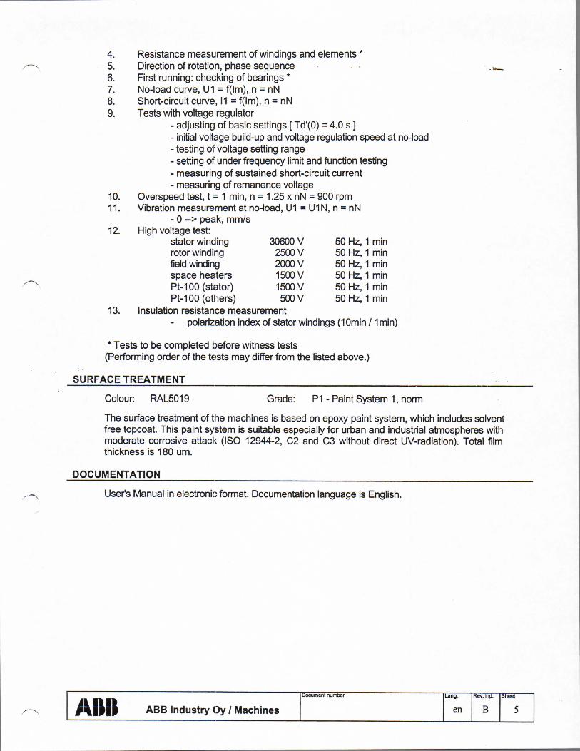
4. Resistance measurement of windings and elements * 5. Direction of rotation, phase sequence 6. First running: checking of bearings * 7. No-ioad curve, U1 = f(im), n = nN 8. Short-circuit curve, 11 = f(im), n = nN 9. Tests with voltage regulator
- adjusting of basic settings [ Td'(O) = 4.0 s ] - Initial voltage buiid-up and voltage regulation speed at no-ioad - testing of voltage setting range - setting of under frequency limit and function testing - measuring of sustained short-circuit current - measuring of remanence voltage
10. Overspeed test, t = 1 min, n = 1.25 x nN = 900 rpm 11. Vibration measurement at no-ioad, U1 = U1N, n = nN
- 0 ~> peak, mm/s 12. High voltage test:
stator winding 30600 V 50 Hz, 1 min rotor winding 2500 V 50 Hz, 1 min fieid winding 2000 V 50 Hz, 1 min space heaters 1500 V 50 Hz, 1 min Pt-100 (stator) 1500 V 50 Hz, 1 min Pt-100 (others) 500V 50 Hz, 1 min
13. insulation resistance measurement polarization index of stator windings (lOmin / 1 min)
* Tests to be completed before witness tests (Performing order of the tests may differ from the listed above.)
S U R F A C E T R E A T M E N T
Colour: RAL5019 Grade: P I - Paint System 1, norm
The surface treatment of the machines is based on epoxy paint system, which includes solvent free topcoat. This paint system is suitable especially for urban and industrial atmospheres with moderate corrosive attack (ISO 12944-2, C2 and C3 without direct UV-radiation). Total film thickness is 180 um.
DOCUMENTATION
User's Manual in electronic format. Documentation language is English.
/VlPIP A B B Industry Oy / Machines
Document number Lang.
en B Sheet
5

3 ACCESSORIES
A C C E S S O R I E S
No pc/pcs Item
PT100 for stator winding
PT100 for sieeve bearings
Anticondensation heater Power 500 - 800 W, Voitage 380 - 480 V
AVR Basier DECS + board According to drawing 6-1103-91-199 (UL-certified)
Voitage transformer for exc.power & actual value measurement 13800/110/110 V, 60 Hz Secondary 1 :110V 3200VA for excitation Secondary 2:110 V 300VA for actual value measurement
Current transformer for short circuit exc.power 400/6.3 A, 10P2.5/3, 60 Hz
Current transformer for actual value measurement 400/1A, 5 VA, CL 0.5, 60 Hz
Current transformer for differential protection Current transformer for measuring and protection KOFD 13.8 CA41 400/5/5 A, 60 Hz C o r e l : C I 00, B-1.0 Core2 :C100, B-1.0
/ ^ I P I P A B B Industry Oy / Machines
Document number Lang. Rev. itxJ. Sheet
/ ^ I P I P A B B Industry Oy / Machines en B 6
6
2
2
1
1
3
1
3
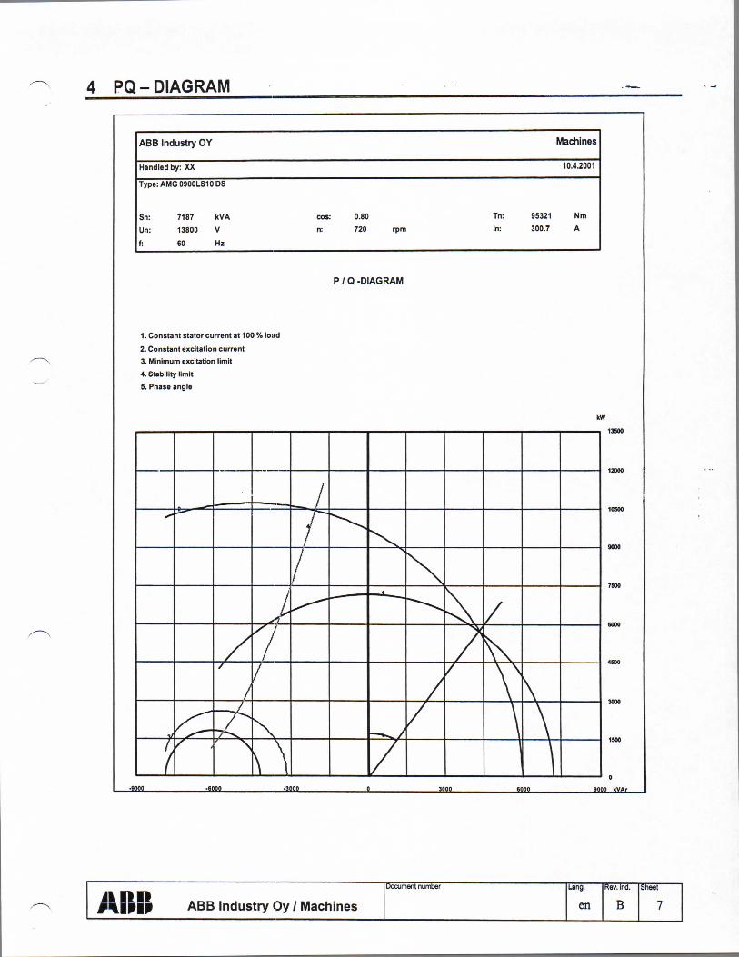
4 PQ-DIAGRAM
ABB Industry OY Machines
Handled by: XX 10.4.2001
Type: AMG 0900LS1 CDS
Sn: 7187 kVA cos: 0.80 Tn: 95321 Nm
Un; 13800 V n: 720 rpm In: 300.7 A
f: 60 Hz
P / Q -DIAGRAM
1. Constant stator current at 100 % load
2. Constant excitation current 3. Minimum excitation limit
4. Stability limit
5. Phase angle
kW
I I I . . I . I I I I I 13500
10S00
9000
7500
6000
4500
3000
1500
0
jam -ma -am s ma ma mqq x v a .
AlPIP A B B Industry Oy / Machines
ITocument number Lang. Rev. ind. Sheet
AlPIP A B B Industry Oy / Machines en B 7

Synchronous Machine AMG 0900LS10 DSEA Section 3 - Technical Specification
Protection for Synchronous Generators
Subject: standard generators Applicable for voltage 1-15 kV and power 3 - 40 MVA
Recommended protection
For generator itself 1. Thermal overload in stator winding; 1 > 2. Network short-circuit; 1» 3. Stator interwinding short-circuit; Differential protection relay 4. Stator earth-fault; Earth-fault relay 5. Overvoltage; Over voltage relay 6. Unbalance load or shorted turns in the same phase; 12 / In 7. Underexcitation and loss of synchronism; Under reactance relay 8. Undervoltage and intermittent loss of voltage; Under voltage relay 9. Temperature supervision of temperature detectors; Pt-lOO-monitoring
Additional protection
Essential rather for prime mover than for generator 1. Frequency disturbance 2. Reverse power
8

Synchronous Machine AMG 0900LS10 DSEA Section 3 - Technicai Specification
Max. Allowed Unbalanced Load for Standard Generators
12 is a counter rotating component of stator current In Max. continuous rate of 12 is 8%

Synchronous Machine AMG 0900LS10 DSEA Section 3 - Technical Specification
Underfrequency Withstanding Capability After Continuous Operation at Rated Output
Subject: standard generators Frequency Load at rated voltage % P.F.=0.8 P.F.= I.O No load
P=Pn P=Pn P=0 100 cont. cont. cont. 96 cont. cont. cont. 95 30 min cont. cont. 92.5 2 min 30 min cont. 90 2 min cont. 87.5 30 min 85 2 min
10
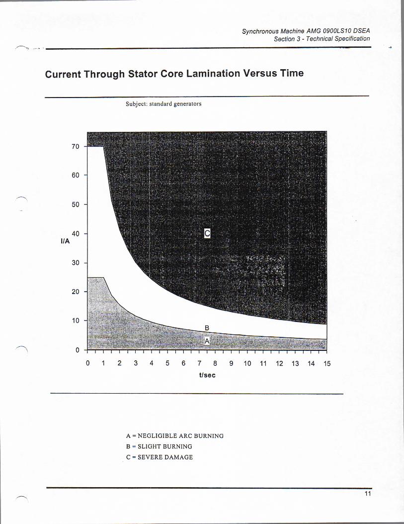
Synchronous Machine AMG 0900LS10 DSEA Section 3 - Technicai Specification
Current Through Stator Core Lamination Versus Time
Subject: standard generators
A = NEGLIGIBLE ARC BURNING B = SLIGHT BURNING C = SEVERE DAMAGE
11

Synchronous Machine AMG 0900LS10 DSEA Section 3 - Technical Specification
Overcurrent Limit for Standard Oenerators
Subject: standard generators
150 % for 2 minutes 125 % for 15 minutes 110% for 1 hour
l n = Rated current 1 = Max. allowed current at six-hour intervals
12

Synchronous Machine AMG 0900LS10 DSEA Section 3 - Technical Specification
Loadability of Standard Generators
Subject; standard generators
1,6 1,6 1
1 ,5 j ! [ [
1 ,5 ; 1 j 1 .4 I ! i ; 1 .4 ; 1 1 :
1 ,3 \ ! ! i 1 1 ,3 . . c 00
; CO j 1,2 1,2
1 .1 ] i
1
0 ,9
i 1 1
0 ,9 1 1 i i 1 1
0 ,9 1 1 1 — 0 1 0 2 0 3 0 4 0 5 0 6 0 m in
110% f o r i hour 100 % continuously
Sn = Rated output S = Output with rated p.F. at six-hour intervals
13