Embed Size (px)
Citation preview
It is of vital importance, before attempting to operate your engine, to read the general 'SAFETY INSTRUCTIONS AND WARNINGS' section on pages 2-5 of this booklet and to strictly adhere to the advice contained therein.
Also, please study the entire contents of this instruction manual, so as to familiarize yourself with the controls and other features of the engine.
Keep these instructions in a safe place so that you may readily refer to them whenever necessary.
It is suggested that any instructions supplied with the model, radio control equipment, etc., are accessible for checking at the same time.
Integrated with O.S. Demand Regulator System
1
2-5
6-7
8-9
10
13-16
30-34
35
42-43
44-45
46
29
17-18
36-37
38-41
11-12
25-28
47
48
CONTENTSSAFETY INSTRUCTIONS AND WARNINGS ABOUT YOUR O.S. ENGINE
NOTES ON INSTALLING COOLING-FAN ANDCLUTCH
NOTES WHEN APPLYING AN ELECTRIC STARTER,INSTALLATION OF THROTTLE SERVO
NOTES ON HEATING THE GLOW PLUG
INTRODUCTION, ENGINE PARTS NAME
BEFORE STARTING,INSTALLATION OF THE ENGINE
INSTALLATION OF THE STANDARDACCESSORIES
ABOUT THE REGURETOR ,ABOUT THE PLUMBING
GLOWPLUGS, CARBURETOR CONTROLS
STARTING
RUNNING-IN ("Breaking-in")
ADJUSTMENT
ADJUSTMENT CHART
CARE AND MAINTENANCE
TROUBLE SHOOTING
ENGINE EXPLODED VIEW & PARTS LIST
CARBURETOR EXPLODED VIEW & PARTS LIST
O.S. GENUINE PARTS & ACCESSORIES
THREE VIEW DRAWING
MEMO
19-21
22-24
! !
2
Remember that your engine is not a "toy", but a highly efficient internal-combustion machine whose power is capable of harming you, or others, if it is misused.As owner, you, alone, are responsible for the safe operation of your engine, so act with discretion and care at all times.If at some future date, your O.S. engine is acquired by another person, we would respectfully request that these instructions are also passed on to its new owner.
SAFETY INSTRUCTIONS AND WARNINGS ABOUT YOUR O.S. ENGINE
The advice which follows is grouped under two headings according to the degree of damage or danger which might arise through misuse or neglect.
WARNINGS NOTES
These cover events which might involve serious (in extreme circumstances, even fatal) injury.
These cover the many other possibilities, generally less obvious sources of danger, but which, under certain circumstances, may also cause damage or injury.
3
! WARNINGS
• •
•
•
•
Never touch, or allow any object to come into contact with, the rotating parts.
Model engine fuel is poison-ous. Do not allow it to come into contact with the eyes or mouth. Always store it in a clearly marked container and out of the reach of children.
Model engine fuel is also highly flammable. Keep it away from open flame, excessive heat, sources of sparks, or anything else which might ignite it. Do not smoke or allow anyone else to smoke, near to it.
Model engines generate considerable heat. Do not touch any part of your engine until it has cooled. Contact with the muffler (silencer), cylinder head or exhaust header pipe, in particular, may result in a serious burn.
Never operate your engine in an en-closed space. Model engines, like auto-mobile engines, exhaust deadly carbon-monoxide. Run your engine only in an open area.
!
4
NOTES
•
•
•
•
•
This engine was designed for model helicopters. Do not attempt to use it for any other purpose.
Mount the engine in your model securely, fol-lowing the manufacturers' recommendations, using appropriate screws and locknuts.
Install an effective silencer (muffler). Frequent close exposure to a noisy exhaust (especially in the case of the more powerful high-speed engines) may eventually impair your hearing and such noise is also likely to cause annoyance to others over a wide area.
Check the linkage to the throttle arm before each flight.
Avoid sudden high r.p.m. immediately after the engine is started, as the clutch will engage and you may be struck by the rotor.
•
•
After starting the engine, carry out any needle-valve readjustments after stopping the rotor by closing the throttle to the lowest r.p.m.. Stop the engine before attempting to make other adjustments to the carburetor.
Use an electric starter. The wearing of safety glasses is also strongly recommended. Press the rotor head down securely.
Take care that the glow plug clip or battery leads do not come into contact with rotating parts.
Adjust the throttle linkage so that the engine stops when the throttle stick and trim lever on the transmitter are fully retarded. Alternatively, the engine may be stopped by cutting off the fuel supply. Never try to stop the engine physically.
•
•
5
! NOTES•
•
•
Take care that loose clothing (ties, shirt sleeves, scarves etc.) do not come into contact with the rotor. Do not carry loose objects (such as pen-cils, screwdrivers, etc.) in a shirt pocket from where they could fall through the rotor disc.
For their safety, keep all onlookers (especially small children) well back (at least 20 feet or 6 meters) when preparing your model for flight. If you have to carry the model to the take-off point with the engine running, be especially cautious. Hold the rotor securely and keep well clear of spectators.
Warning! lmmediately after a glowplug-ignition engine has been run and is still warm, conditions sometimes exist whereby it is just possible for the engine to restart when turned over WITHOUT the glowplug battery being reconnected. Remember this if you wish to avoid the risk of accidents.

6
Notes on installing cooling fan and clutch
Do not use a tool which locks piston when installing a cooling-fan and clutch, or top of the piston may be damaged. Also, do not insert a screw driver or the similar into the exhaust port.
It is recommended to use Crankshaft Clamp 91 (Code No.71530510) available as an optional tool.
With this engine, the cover plate cannot be removed when the piston is at BDC due to engine construction.When it is required to remove the cover plate, be sure to position the piston at TDC.
7
Notes on installing cooling fan and clutch
Do not grip the engine mounting beams with a vise, or the crankcase will be distorted which will result in engine breaking.
Vise
Beam Mount
8
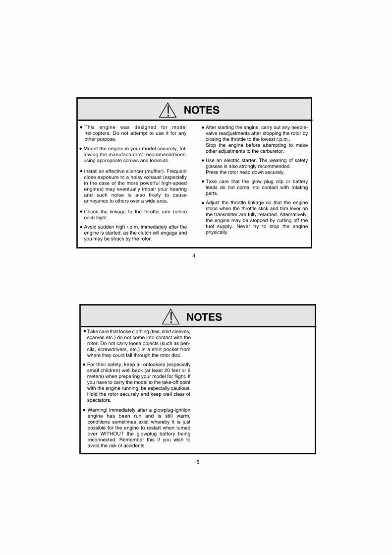
NOTES WHEN APPLYING AN ELECTRIC STARTER
Because of the initial tightness, of the piston/sleeve assembly a standard electric starter may have difficulty in rotating the engine when cold, before it has been adequately run-in. In this case, use a high-torque type starter.
Do not over-prime. This could cause a hydraulic lock and damage the engine on application of the electric starter.
If over-primed, remove glowplug, close needle-valve and apply starter to pump out surplus fuel. Cover the head with a rag to prevent pumped out fuel from getting into your eyes.
9
F
J J
F
2834
27 33
A
B
90° 90°
A=B
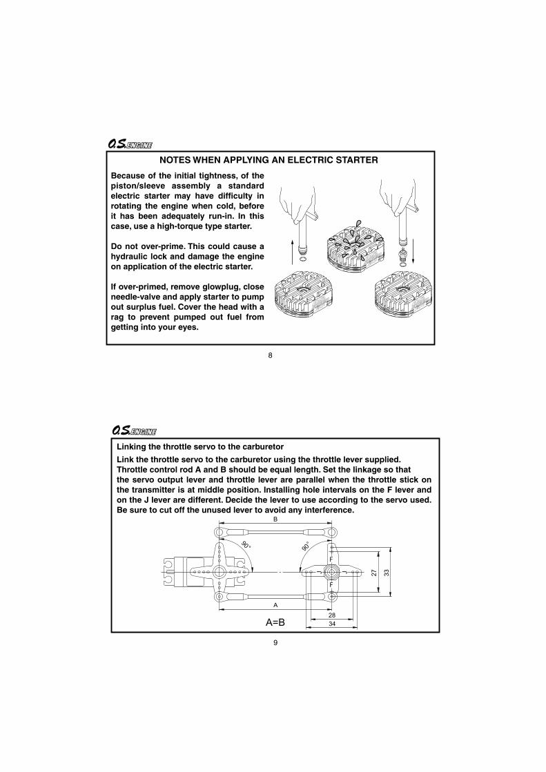
Linking the throttle servo to the carburetor
Link the throttle servo to the carburetor using the throttle lever supplied.Throttle control rod A and B should be equal length. Set the linkage so thatthe servo output lever and throttle lever are parallel when the throttle stick on the transmitter is at middle position. Installing hole intervals on the F lever and on the J lever are different. Decide the lever to use according to the servo used. Be sure to cut off the unused lever to avoid any interference.

10
Note on heating the glow plug Example
The heatsink head and the crankcase of on the engine is treated with an anodized finish which does not conduct current. Therefore, when heating the glow plug, connect one lead to the glow plug and the other to the cover plate retaining screw.
11
INTRODUCTION
Standard accessories
Glow Plug No.8
Check Valve
Head Gasket (0.2mm)
This is the O.S. SPEED version of the 91HZ-R developed expressly for the 3D flights.The equipped DRS (Demand Regulator System) ensures an always steady fuel supply which is required for 3D flights which require repeated vigorous attitude changes. The new 61G carburetor is equipped with twin needles which enable adjustment of the idling/hovering and high speed mixture independently.The cover plate has a cell to accept a sensor designed to install in the cover plate from Futaba GY-701 Governor.
As delivered, the engine has the
carburetor lightly fit into the intake.
Secure it changing the angle according
to the model.
NOTE

12
ENGINE PARTS NAME
Heatsink Head
CarburetorTypr 61G
CrankshaftPropeller nut
Crankcase
Glowplug
Beam Mount
Reguretor
High SpeedNeedle Valve
Fuel Inlet
Mixture Control Valve
Throttle Lever
Idle Mixture Control Screw
Mixture ControlValve Stopper
Thrust Washer
Carburetor Rubber Gasket
Medium Speed Needle Valve
Thermo Insulater
Cover Plate
13
Items necessary for starting
Tools, accessories, etc.The following items are necessary for operating the engine.
BEFORE STARTING
Glow PlugO.S. No.8 is supplied with the engine.
Battery leads
Glowplug batteryThe power source for heating the glowplug may be either a large heavy-duty 1.5volt dry cell, Ni-cd battery or glowplug Igniter.
1.5 volt dry cell
These are used to conduct current from the battery to the glowplug. Basically, two leads, with clips, are required, but, for greater conve-nience, twin leads with special glowplug connectors, as shown on the right, are commercially available.
Battery leads
glowplug Igniter
Make sure glowplug element glows bright red inside room or shadow.
Battery leads
In case of 1.5volt dry cell
12V BatteryStarter
Electric starter and starterbattery An electric starter is recom-mended for starting.
Hexagon starting shaftThis shaft mounted on an electric starting motor is driven into the shaft cup to turn the engine.
14
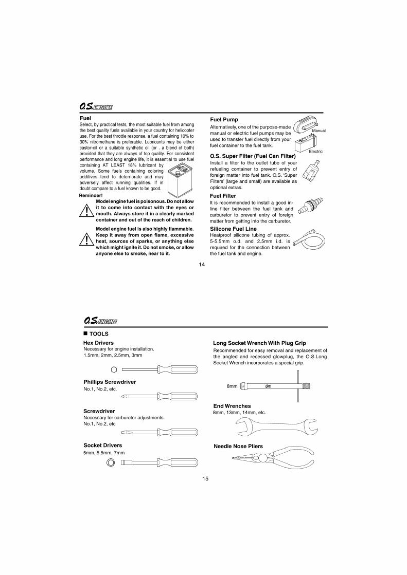
Select, by practical tests, the most suitable fuel from among the best quality fuels available in your country for helicopter use. For the best throttle response, a fuel containing 10% to 30% nitromethane is preferable. Lubricants may be either castor-oil or a suitable synthetic oil (or . a blend of both) provided that they are always of top quality. For consistent performance and long engine life, it is essential to use fuel containing AT LEAST 18% lubricant by volume. Some fuels containing coloring additives tend to deterriorate and may adversely affect running qualities. If in doubt compare to a fuel known to be good.
Model engine fuel is poisonous. Do not allow it to come into contact with the eyes or mouth. Always store it in a clearly marked container and out of the reach of children.
Reminder!
Fuel
Model engine fuel is also highly flammable. Keep it away from open flame, excessive heat, sources of sparks, or anything else which might ignite it. Do not smoke, or allow anyone else to smoke, near to it.
Alternatively, one of the purpose-made manual or electric fuel pumps may be used to transfer fuel directly from your fuel container to the fuel tank.
Manual
Electric
Install a filter to the outlet tube of your refueling container to prevent entry of foreign matter into fuel tank. O.S. ‘Super Filters’ (large and small) are available as optional extras.
O.S. Super Filter (Fuel Can Filter)
Fuel Filter
Heatproof silicone tubing of approx. 5-5.5mm o.d. and 2.5mm i.d. is required for the connection between the fuel tank and engine.
Fuel Pump
Silicone Fuel Line
It is recommended to install a good in-line filter between the fuel tank and carburetor to prevent entry of foreign matter from getting into the carburetor.
15
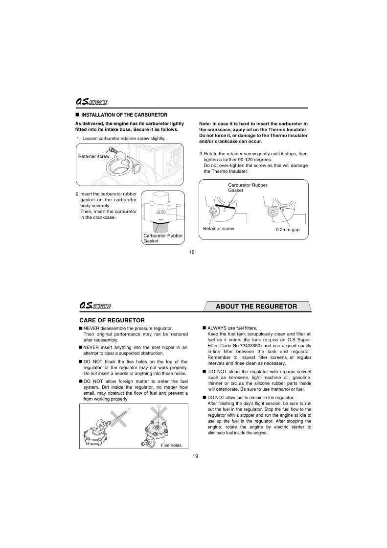
TOOLS
Screwdriver
Necessary for engine installation.1.5mm, 2mm, 2.5mm, 3mm
Necessary for carburetor adjustments.No.1, No.2, etc
Phillips ScrewdriverNo.1, No.2, etc.
Socket Drivers5mm, 5.5mm, 7mm
Hex Drivers
8mm
Recommended for easy removal and replacement of the angled and recessed glowplug, the O.S.Long Socket Wrench incorporates a special grip.
End Wrenches8mm, 13mm, 14mm, etc.
Needle Nose Pliers
Long Socket Wrench With Plug Grip

16
INSTALLATION OF THE ENGINE
The under-surfaces of all O.S. engine beam mounting lugs are precision machined flat and exactyly parallel to the engine's horizontal axis. It is essential that the engine mounts in the model are also accurately made and aligned. If they are not, they will cause stress and distortion within the engine itself, probably resulting in loss of performance and internal damage.The recommended screws for securing the engine to the engine mounts in the model are 4mm or 4-40 steel Allen type. It is also advisable to use lock washers or LOCTITE to prevent nuts from loosening.
Front view
CORRECT
Side viewTop surfaces are in the same plane.
Re-align the surfaces as necessary
INCORRECT
Top surfaces are not in the same plane.
Top surfaces are not in the same plane.
Engine does not rest firmly.
Make sure that only the under-surfaces of the engine’s mounting lugs are in contact with the engine mount.
17
INSTALLATION OF THE STANDARD ACCESSORIES
INSTALLING THE GLOWPLUG
Install washer on glowplug and insert carefully into Heatsink-head, making sure that it is not cross-threaded before tightening firmly.
Glow plugWasher
ABOUT THE HEAD GASKETThe engine is installed with a 0.1mm thick head gasket at the factory. When a 15% nitro fuel is used, run the engine as it is. When a 30% nitro fuel is used, replace with a 0.2mm thick gasket supplied or add 0.2mm thick gasket for easier tuning.
18
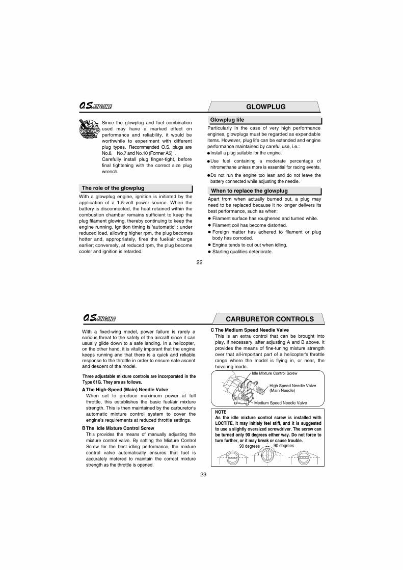
INSTALLATION OF THE CARBURETOR
1.
2.
Retainer screw
Carburetor RubberGasket
0.2mm gapCarburetor RubberGasket
Insert the carburetor rubber gasket on the carburetor body securely.Then, insert the carburetor in the crankcase.
Note: In case it is hard to insert the carburetor in the crankcase, apply oil on the Thermo Insulater. Do not force it, or damage to the Thermo Insulater and/or crankcase can occur.
Rotate the retainer screw gently until it stops, then tighten a further 90-120 degrees.Do not over-tighten the screw as this will damage the Thermo Insulater.
3.
Loosen carburetor retainer screw slightly.
Retainer screw
As delivered, the engine has its carburetor lightly fitted into its intake boss. Secure it as follows.
19
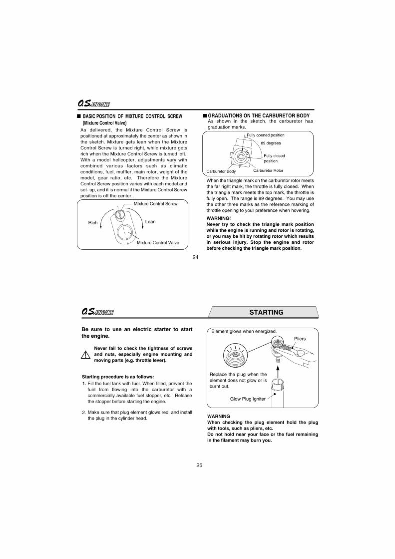
CARE OF REGURETORNEVER disassemble the pressure regulator. Their original performance may not be restored after reassembly.
NEVER insert anything into the inlet nipple in an attempt to clear a suspected obstruction.
ALWAYS use fuel filters. Keep the fuel tank scrupulously clean and filter all fuel as it enters the tank (e.g.via an O.S.'Super-Filter' Code No.72403050) and use a good quality in-line filter between the tank and regulator. Remember to inspect filter screens at regular intervals and rinse clean as necessary.
DO NOT clean the regulator with organic solvent such as kerosene, light machine oil, gasoline, thinner or crc as the silicone rubber parts inside will deteriorate. Be sure to use methanol or fuel.
DO NOT allow fuel to remain in the regulator. After finishing the day's flight session, be sure to run out the fuel in the regulator. Stop the fuel flow to the regulator with a stopper and run the engine at idle to use up the fuel in the regulator. After stopping the engine, rotate the engine by electric starter to eliminate fuel inside the engine.
DO NOT allow foreign matter to enter the fuel system. Dirt inside the regulator, no matter how small, may obstruct the flow of fuel and prevent a from working properly.
DO NOT block the five holes on the top of the regulator, or the regulator may not work properly. Do not insert a needle or anything into these holes.
ABOUT THE REGURETOR
Five holes

20
ABOUT THE PLUMBING
Carry out plumbing referring to a sketch on page 21.
Connect silicone tubing cut into approx. 10cm to the nipple on the cover plate.
Then, connect the check valve supplied with the engine as sketched (Be aware of the direction.) It is suggested to install a stopper as shown in the sketch.
When refueling, remove this stopper to release pressure in the fuel tank.
Connect the fuel line to the nipple on the regulator.
Be sure to equip a commercially available in-line filter to avoid dust entering the regulator.
Note:Since the muffler pressurized fuel feed is not used with this engine, plug a nipple on the muffler or replace it with a bolt.
21
Fuel tank
Fuel Stopper (commercially available)
Fuel Filter (commercially available)
Check valve
Check valve Fuel Stopper (commercially available)
T Nipple
Remove when refuelling
(commercially available)
Be aware of direction
Grooved part shouldface the fuel tank.
Silicone tubingapprox.10cm
(commercially available)
JAPA
N
22
GLOWPLUG
The role of the glowplug
Glowplug life
Particularly in the case of very high performance engines, glowplugs must be regarded as expendable items. However, plug life can be extended and engine performance maintained by careful use, i.e.:
Install a plug suitable for the engine.
Use fuel containing a moderate percentage of nitromethane unless more is essential for racing events.
Do not run the engine too lean and do not leave the battery connected while adjusting the needle.
With a glowplug engine, ignition is initiated by the application of a 1.5-volt power source. When the battery is disconnected, the heat retained within the combustion chamber remains sufficient to keep the plug filament glowing, thereby continuing to keep the engine running. Ignition timing is 'automatic' : under reduced load, allowing higher rpm, the plug becomes hotter and, appropriately, fires the fuel/air charge earlier; conversely, at reduced rpm, the plug become cooler and ignition is retarded.
Apart from when actually burned out, a plug may need to be replaced because it no longer delivers its best performance, such as when:
When to replace the glowplug
Filament surface has roughened and turned white. Filament coil has become distorted.Foreign matter has adhered to filament or plug body has corroded.Engine tends to cut out when idling.Starting qualities deteriorate.
Since the glowplug and fuel combination used may have a marked effect on performance and reliability, it would be worthwhile to experiment with different plug types. Recommended O.S. plugs are No.8, No.7 and No.10 (Former A5) . Carefully install plug finger-tight, before final tightening with the correct size plug wrench.
23
CARBURETOR CONTROLS
With a fixed-wing model, power failure is rarely a serious threat to the safety of the aircraft since it can usually glide down to a safe landing. In a helicopter, on the other hand, it is vitally imporant that the engine keeps running and that there is a quick and reliable response to the throttle in order to ensure safe ascent and descent of the model.
The High-Speed (Main) Needle ValveWhen set to produce maximum power at full throttle, this establishes the basic fuel/air mixture strength. This is then maintained by the carburetor's automatic mixture control system to cover the engine's requirements at reduced throttle settings.
The Idle Mixture Control ScrewThis provides the means of manually adjusting the mixture control valve. By setting the Mixture Control Screw for the best idling performance, the mixture control valve automatically ensures that fuel is accurately metered to maintain the correct mixture strength as the throttle is opened.
Three adjustable mixture controls are incorporated in the Type 61G. They are as follows.
A
B
The Medium Speed Needle ValveThis is an extra control that can be brought into play, if necessary, after adjusting A and B above. It provides the means of fine-tuning mixture strength over that all-important part of a helicopter's throttle range where the model is flying in, or near, the hovering mode.
C
Idle MIxture Control Screw
High Speed Needle Valve(Main Needle)
Medium Speed Needle Valve
NOTE
90 degrees90 degrees
As the idle mixture control screw is installed with LOCTITE, it may initialy feel stiff, and it is suggested to use a slightly oversized screwdriver. The screw can be turned only 90 degrees either way. Do not force to turn further, or it may break or cause trouble.
24
BASIC POSITION OF MIXTURE CONTROL SCREW(Mixture Control Valve)
Rich
Mixture Control Valve
MIxture Control Screw
Lean
89 degrees
When the triangle mark on the carburetor rotor meets the far right mark, the throttle is fully closed. When the triangle mark meets the top mark, the throttle is fully open. The range is 89 degrees. You may use the other three marks as the reference marking of throttle opening to your preference when hovering.
WARNING!Never try to check the triangle mark position while the engine is running and rotor is rotating, or you may be hit by rotating rotor which results in serious injury. Stop the engine and rotor before checking the triangle mark position.
Carburetor RotorCarburetor Body
Fully closedposition
Fully opened position
As shown in the sketch, the carburetor has graduation marks.
GRADUATIONS ON THE CARBURETOR BODY
As delivered, the Mixture Control Screw is positioned at approximately the center as shown in the sketch. Mixture gets lean when the Mixture Control Screw is turned right, while mixture gets rich when the Mixture Control Screw is turned left.With a model helicopter, adjustments vary with combined various factors such as climatic conditions, fuel, muffler, main rotor, weight of the model, gear ratio, etc. Therefore the Mixture Control Screw position varies with each model and set- up, and it is normal if the Mixture Control Screw position is off the center.
25
!
STARTING
Be sure to use an electric starter to start the engine.
Fill the fuel tank with fuel. When filled, prevent the fuel from flowing into the carburetor with a commercially available fuel stopper, etc. Release the stopper before starting the engine.
1.
2.
Starting procedure is as follows:
WARNINGWhen checking the plug element hold the plug with tools, such as pliers, etc.Do not hold near your face or the fuel remaining in the filament may burn you.
Glow Plug Igniter
Pliers
Element glows when energized.
Replace the plug when the element does not glow or is burnt out.
Make sure that plug element glows red, and install the plug in the cylinder head.
Never fail to check the tightness of screws and nuts, especially engine mounting and moving parts (e.g. throttle lever).
26
Open
1.
2.
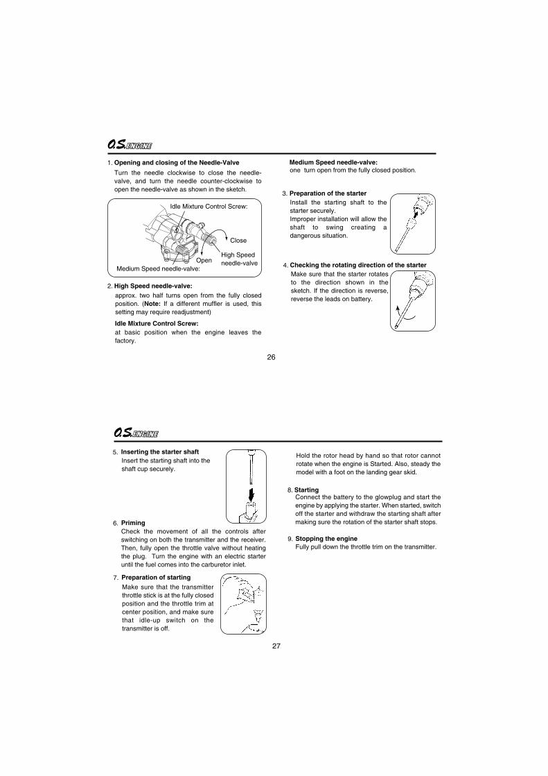
Opening and closing of the Needle-Valve
Turn the needle clockwise to close the needle-valve, and turn the needle counter-clockwise to open the needle-valve as shown in the sketch.
High Speed needle-valve:approx. two half turns open from the fully closed position. (Note: If a different muffler is used, this setting may require readjustment)
Idle Mixture Control Screw:at basic position when the engine leaves the factory.
one turn open from the fully closed position.Medium Speed needle-valve:
Close
4. Checking the rotating direction of the starterMake sure that the starter rotates to the direction shown in the sketch. If the direction is reverse, reverse the leads on battery.
3. Preparation of the starterInstall the starting shaft to the starter securely. Improper installation will allow the shaft to swing creating a dangerous situation.
High Speedneedle-valve
Idle Mixture Control Screw:
Medium Speed needle-valve:
27
5. Inserting the starter shaftInsert the starting shaft into the shaft cup securely.
6. PrimingCheck the movement of all the controls after switching on both the transmitter and the receiver. Then, fully open the throttle valve without heating the plug. Turn the engine with an electric starter until the fuel comes into the carburetor inlet.
Stopping the engineFully pull down the throttle trim on the transmitter.
StartingConnect the battery to the glowplug and start the engine by applying the starter. When started, switch off the starter and withdraw the starting shaft after making sure the rotation of the starter shaft stops.
Preparation of starting7.
8.
9.
Hold the rotor head by hand so that rotor cannot rotate when the engine is Started. Also, steady the model with a foot on the landing gear skid.
Make sure that the transmitter throttle stick is at the fully closed position and the throttle trim at center position, and make sure that idle-up switch on the transmitter is off.

28
In case the engine does not stop.Hold the rotor head, and pinch the fuel line to stop the fuel supply. If it still does not stop, pull off the fuel line from the carburetor.It is necessary to readjust the throttle linkage so that the carburetor rotor is fully closed when the throttle stick and throttle trim on the transmitter are fully pulled Down.
NOTE:If the throttle response is poor or the engine stops due to a temporarily over-rich mixture im-mediately after the engine is started, pinch the fuel line for one or two seconds until the engine r.p.m. increase and the engine runs steadily.
Reminder!Never touch, or allow any object to come into contact with, the rotating rotor.
29
All internal-combustion engines benefit, to some degree, from extra care when they are run for the first few times known as running-in or breaking-in.
This allows the working parts to mate together under load at operating temperature.
However, because O.S. engines are made with the aid of the finest modern precision machinely and from the best and most suitable materrials, only a very short and simple running-in procedure is required and can be carried out with the engine installed in the model.
RUNNING-IN ("Breaking-in")
Main needle is set two and half turns open from fully closed position and the medium speed needle is set one turn open from fully closed position when the engine leaves the factory.
It is expected with these needle settings the engine may run rich. During running-in, hover the model making sure the engine runs rich.
Also, during running-in since the mixture is rich, you may feel uneven engine rpm and more fuel consumption.
In the next section, needle adjustments to optimum position from running-in position are explained. Be sure to run the engine a little on the rich side so that if will have a long life expectancy.

30
ADJUSTMENT
Please observe the following before beginning to make any adjustment.
The general course of adjustment procedure is shown in the ADJUSTING CHART and is correct for a fuel containing 20% lubricant and 15-30% nitromethane.
Bear in mind that fuels containing relatively large percentages of power-boosting nitromethane operate at richer mixture settings than are needed for mild fuels and will, therefore, require the High-Speed Needle Valve to be readjusted accordingly. The type and percentage of lubricant used is also a factor here, as noted later in these instructions.
This carburetor is not equipped with a throttle stop screw. Instead, idle speed is adjusted by means of the throttle trim lever on the trans-mitter.
High-Speed Needle Valve. Turn this approximately 30 degrees (3 to 4 clicks) at a time, when making initial adjustments; then in steps of approximately 15 degrees (1 to 2 clicks) when making final adjustments.
Medium-Speed Needle Valve. Turn approximately 30 degrees (3 to 4 clicks) at a time.
Idle Mixture Control Screw. Turn approximately 5 degrees at a time. It turns approximately 90 degrees both sides from the center. Turn left to enrich the idle mixture and turn right to lean the idle mixture.
31
As a safety measure, first check the transmitter controls, including the throttle stick and trim lever positions, and hold the main rotor securely before starting the engine.
Warm the engine by allowing it to idle for about 30 seconds. If the engine stops, advance the throttle trim lever slightly to increase the idle rpm. Then open the throttle sufficiently to 'float' the model above the ground. lf, at this time, the engine is slow to pick up and produces an excess of exhaust smoke, the mixture is too rich. Correct this condition by turning the Mixture Control Screw clockwise 5 degrees. lf the mixture is extremely rich, engine rpm will become unstable: opening the throttle will produce a great deal of smoke and rpm may drop suddenly or the engine may stop.
ADJUSTMENT PROCEDURE
1.
This condition may also be initiated by an excessively prolonged warming-up period. lf, on the other hand, the mixture is too Iean, this wiIl be indicated by a marked lack of exhaust smoke and a tendency for the engine to cut out when the throttle is opened. ln this case, turn the Mixture Control Screw counter-clockwise 5 degrees to enrich the mixture.

32
Having provisionally set the idle mixture, the next step is to adjust the mixture for hovering flight.Hover the model and actuate the throttle to observe response over the medium speed range. lf the engine smokes excessiveIy and throttle response is poor, the mixture is too rich ; in which case, land the model and turn the High-Speed Needle Valve clockwise. Do not close the High-Speed NeedIe Valve more than the recommended initial adjustment (3 to 4 clicks) at a time, keeping it a little on the rich side at this stage. DO NOT touch the Medium Speed Needle Valve.
lf, on the other hand, hovering is not stable and response to the throttIe is over-sensitive, or if the engine tends to overheat, this indicates that the mixture is too lean and should be corrected by turning the High-Speed Needle Valve counter-clockwise.
2. After about 10 seconds of idling, open the throttle to 'float' the model. lf the transition is smooth, the idle mixture is O.K. If the symptoms of either rich or Iean running are observed, readjust the Idle Mixture Control Screw accordingly.
NOTE: With this carburetor, neither the Idle Mixture Control Screw adjustment, nor the Medium Speed Needle Valve adjustment will have any effect on mixture strength when the throttle is fully (or almost fully) open.
Throttle OpeningFully Closed 1/3 2/3 Fully Open
Fuel F
lowM
aximum
Minim
um
Adjustment range of Idle MixtureControl Screw
Adjustment range of MediumSpeed Needle Valve
Needle Valve too far open
Needle Valve too far closed
High Speed Needle Valve Setting variesaccording to the curve.
When satisfactory hovering flight has been achieved, land the modeI again and re-check the engine's idle qualities.
33
Now re-check hovering performance It may be found that (with the High-Speed Needle Valve now set for optimum full-throttle performance) hovering will reveal symptoms of slightly lean running at medium speeds. DO NOT touch the High-Speed Needle Valve.
Now adjust the High-Speed Needle Valve to achieve the best performance when the model is flying at full throttle. lf, at full throttle, acceleration is poor, the exhaust unduly smoky and the model fails to reach expected straight line speed, the mixture is too rich and the High-Speed Needle Valve setting will need to be reduced. lf, however, after smoothly acceIerating to satisfactory high-speed straight and level flight, power is lost when the model is puIled up into a climb, the mixture is too lean. ln this case, land the model immediately and readjust thw High-Speed Needle Valve to a richer setting.
3.
4. Having now found the optimum setting for the High-Speed Needle Valve, re-check the engine's idle performance, fine tuning the Idle Mixture Control Screw, if necessary, to perfect the idle.
5.
It is at this point that the Medium Speed Needle Valve, previously set one and a half turns open, may be brought into operation. Open the Medium Speed Needle Valve 30 degrees, or 3-4 clicks, then fine tune until the optimum hovering performance is obtained. If on the other hand, hovering reveals rich running, close the Medium Speed Needle Valve gradually until the optimum hovering performance is obtained.
34
CARBURETOR CLEANLINESS
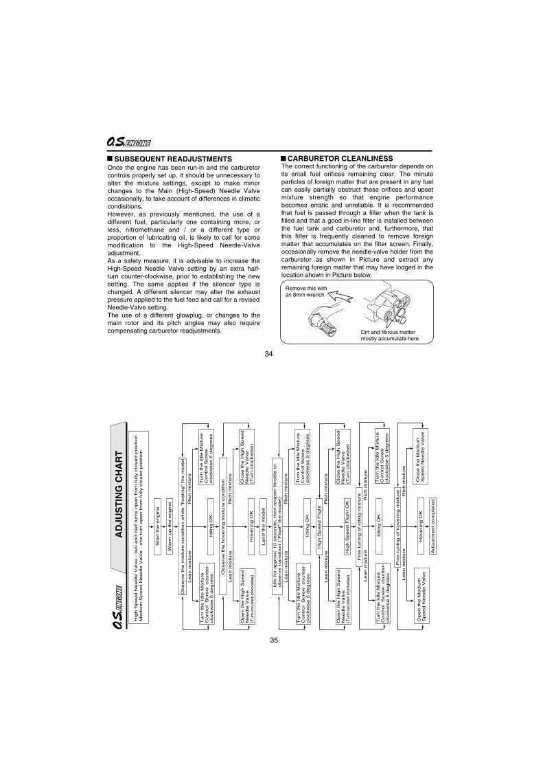
Remove this with an 8mm wrench
Dirt and fibrous mattermostly accumulate here
SUBSEQUENT READJUSTMENTSOnce the engine has been run-in and the carburetor controls properly set up, it should be unnecessary to alter the mixture settings, except to make minor changes to the Main (High-Speed) Needle Valve occasionally, to take account of differences in climatic condisitions.However, as previously mentioned, the use of a different fuel, particularly one containing more, or less, nitromethane and / or a different type or proportion of lubricating oil, is likely to call for some modification to the High-Speed Needle-Valve adjustment.As a safety measure, it is advisable to increase the High-Speed Needle Valve setting by an extra half-turn counter-clockwise, prior to establishing the new setting. The same applies if the silencer type is changed. A different silencer may alter the exhaust pressure applied to the fuel feed and call for a revised Needle-Valve setting.The use of a different glowplug, or changes to the main rotor and its pitch angles may also require compensating carburetor readjustments.
The correct functioning of the carburetor depends on its small fuel orifices remaining clear. The minute particles of foreign matter that are present in any fuel can easily partially obstruct these orifices and upset mixture strength so that engine performance becomes erratic and unreliable. It is recommended that fuel is passed through a filter when the tank is filled and that a good in-line filter is installed between the fuel tank and carburetor and, furthermore, that this filter is frequently cleaned to remove foreign matter that accumulates on the filter screen. Finally, occasionally remove the needle-valve holder from the carburetor as shown in Picture and extract any remaining foreign matter that may have lodged in the location shown in Picture below.
35
AD
JUS
TIN
G C
HA
RT
Hig
h S
peed N
eedle
Valv
e -
tw
o a
nd h
alf turn
s o
pen fro
m fully c
losed p
ositio
n.
Mediu
m S
peed N
eedle
Valv
e -
one t
urn
open fro
m fully c
losed p
ositio
n.
Sta
rt the e
ngin
e
Warm
up the e
ngin
e
Observ
e the m
ixtu
re c
ond
itio
n w
hile "
floating"
the m
odel
Turn
the Idle
Mix
ture
Contr
ol
Scre
w counte
r-clo
ckw
ise 5
degre
es
Idling O
K
Turn
the Idle
Mix
ture
Contr
ol S
cre
wclo
ckw
ise 5
degre
es
Lean m
ixtu
reR
ich m
ixtu
re
Observ
e the h
overing m
ixtu
re c
onditio
n
Open the H
igh S
peed
Needle
Valv
e(T
urn
counte
r-cl
ock
wis
e)
Hovering O
K
Lean m
ixtu
reR
ich m
ixtu
re
Clo
se the H
igh S
peed
Needle
Valv
e(T
urn
clo
ckw
ise)
Land
the m
odel
Idle
for
appro
x: 10 s
econds, th
en r
eopen thro
ttle
to
observ
e tra
nsitio
n (
"Flo
at"
the m
odel)
Idling O
K
Lean m
ixtu
reR
ich m
ixtu
re
Hig
h S
peed F
light
Lean m
ixtu
reR
ich m
ixtu
re
Hig
h S
peed F
light O
K
Fin
e tunin
g o
f hovering m
ixtu
re
Open the M
ediu
mS
peed N
eedle
Valv
eH
overing O
K
Adju
stm
ent com
ple
ted
Open the H
igh S
peed
Needle
Valv
e(T
urn
counte
r-cl
ock
wis
e)
Clo
se the H
igh S
peed
Needle
Valv
e(T
urn
clo
ckw
ise)
Fin
e tunin
g o
f id
ling m
ixtu
re
Lean m
ixtu
reR
ich m
ixtu
re
Idling O
K
Lean m
ixtu
reR
ich m
ixtu
re
Clo
se the M
ediu
mS
peed N
eedle
Valv
e
Turn
the Idle
Mix
ture
Contr
ol S
cre
wclo
ckw
ise 5
degre
es
Turn
the Idle
Mix
ture
Contr
ol S
cre
wclo
ckw
ise 5
degre
es
Turn
the Idle
Mix
ture
Contr
ol
Scre
w counte
r-clo
ckw
ise 5
degre
es
Turn
the Idle
Mix
ture
Contr
ol
Scre
w counte
r-clo
ckw
ise 5
degre
es
36
CARE AND MAINTENANCE
Please pay attention to the matters described below to ensure that your engine serves you well in regard to performance, reliability and long life.
As previously mentioned, it is vitally important to avoid operating the engine in conditions where dust, disturbed by the propeller, may be deposited on the engine and enter its working parts.
Remember to keep your fuel container closed to prevent foreign matter from contaminating the fuel.
If these precautions are neglected, restriction of fuel flow may cause the engine to cut out, or the fuel/air mixture to become too lean causing the engine to overheat.
Clean these filters periodically.
The use of modern high-performance alcohol based model engine fuels, while promoting cooler running, improved anti-detonation combustion and increased power, have the disadvantage of causing corrosion due to the acid by-products of combustion. The use of nitromethane in the fuel can also contribute to the problem.
Install a fuel filter to prevent foreign matter in the fuel container from entering the fuel tank. O.S. Super Filters (L) and (S) are available as optional extras.
Install an in-line fuel filter between the tank and carburetor to prevent foreign matter in the tank from entering the carburetor.
37
Do not close the needle-valve and mixture control valve too far as this will cause a lean setting and over heating of the engine. This can, in turn, create nitromethane oxide leading to internal rusting of the engine. Always adjust the needlevalve slightly on the rich side of peak rpm.
Do not leave unused fuel in the engine at the conclusion of a day’s flying. Accepted practice is to cut off the fuel supply while the engine is still running at full throttle, then expel as much fuel residue as possible by turning the engine over 5-10 seconds with the electric starter. Finally, inject some after-run oil through the glowplug hole and turn the engine over several times by hand.
When the engine is not to be used for some months (for example, as between flying seasons), a worthwhile precaution is to remove it from the airframe and, after washing off the exterior with alcohol (not gasoline nor kerosene), remove carefully the carburetor with intake pipe, glow plug and all silicone tubing and put them safely aside. Then, immerse the engine in a container of alcohol. Rotate the crankshaft while the engine is immersed. If foreign matter is visible in the alcohol, rinse the engine again in clean alcohol. Finally, shake off and dry the alcohol, and inject some after-run oil in the glowplug hole and rotate the crankshaft several times by hand. Reinstall the carburetor with intake pipe and glowplug on the engine and keep it in a dry place after putting in a vinyl bag.

38
TROUBLE SHOOTING
Symptom
Cause Corrective action
Engine fails to fire.
Fuel tank is empty.Fuel not reaching the engine.
Fill the tank with fuel and repeat.Priming procedure.
Glowplug element is burnt out.Glowplug battery discharged
Replace glowplug.Recharge or replace the battery.
Clogged fuel filter. Silencer inside is dirty. Clean or replace fuel filter. Clean inside silencer.
Over priming Remove glowplug and pump out excess fuel.
Fuel tubing is disconnected. Connect fuel tubing securely.Fuel tubing is kinked, split or has a hole. Check the tubing carefully and replace if necessary.
Incorrect carburetor settings Return the needle valve and mixture control valve to basic position.
Incorrect servo linkage Reconnect linkage after setting servo at neutral.
Reverse rotating direction of electric starter. Mare sure the engine rotates counter clockwiseseen from crankshaft side.
39
Symptom
Cause Corrective action
Engine fires intermittently but does not run.
Insufficient fuel in the tank. Fill the tank with fuel.
Deteriorated glowplug Replace glowplug.
Clogged fuel filterSilencer inside is dirty.
Clean or replace fuel filter.Clean inside silencer.
Engine overheated Wait until engine has cooled.
Disconnecting plug battery too soon.Do not disconnect plug battery and wait untilthe r.p.m. becomes stable.
Air bubbles in fuelFit O rings to the tank screws to prevent bubbles.

40
Symptom
Cause Corrective action
Symptom
Cause Corrective action
Unstable idle
Unsuitable glowplug Use suggested glowplug in the instructions.
Unsuitable fuel Do not use extremely high nitro or low oil fuel.
Silencer is disconnected or is loose Install silencer securely.
Not reaching expected peak r.p.m.
Insufficient warming up or running-in.Set the needle only after warming up. Complete running-in.
Silencer or manifold is not securely connectedor disconnected.
Check the connections and secure them.
Fuel tubing from tank to is split or broken. Replace the tubing.
41
Symptom
Cause Corrective action
Symptom
Cause Corrective action
Poor response
Deteriorated glowplug Replace glowplug.
Incorrect carburetor settings Readjust low r.p.m. range with metering needle and mixture control valve.
Poor r.p.m. drop
Too much throttle opening at idle.Lower the throttle trim to adequate positionto lower idle r.p.m.
Incorrect carburetor fitting Fit carburetor securely.
Inaccurate linkageRecheck the throttle opening againstthe pitch angle.
Needle-valve closed too far. Open needle-valve slightly

42
EN
GIN
E E
XP
LO
DE
D V
IEW
7987
1055
7987
1140
7987
1150
M2.
6x18
M3x
12
M3x
15
CA
P S
CR
EW
SE
TS
( 10p
cs./s
ets)
Cod
e N
o.S
ize
Pcs
. use
d in
an
engi
ne
Cylin
der H
ead
Reta
inin
g Sc
rew
(6pc
s.)
Cov
er P
late
Ret
aini
ng S
crew
(4pc
s.)
Ret
aine
r Scr
ew (1
pc.)
Typ
e of
scr
ew
C…
Cap
Scr
ew
*
17
C.M
3x15
1
2
3 45
6 7
8
910
1112
13
1415
12-1
16
C.M
3x12
18
C.M
2.6x
18
1-1
43
The
spe
cific
atio
ns a
re s
ubje
ct to
alte
ratio
n fo
r im
prov
emen
t with
out n
otic
e.
EN
GIN
E P
AR
TS
LIS
T
Hea
tsin
k H
ead
H
ead
Gas
ket (
0.1m
m)
Cyl
inde
r Li
ner
Pis
ton
Rin
gP
isto
nP
isto
n P
inP
isto
n P
in R
etai
ner
(2pc
s.)
Con
nect
ing
Rod
Car
bure
tor
Com
plet
e 6
1GP
rope
ller
Nut
Thr
ust W
ashe
rC
rank
shaf
t Bal
l Bea
ring
(Fro
nt)
Car
bure
tor
Ret
aine
r A
ssem
bly
"
O"
Rin
gC
rank
case
Cra
nksh
aft B
all B
earin
g (R
ear)
Cra
nksh
aft
Cov
er G
aske
tC
over
Pla
teN
ippl
e (N
o.1)
Glo
w P
lug
No.
8C
heck
Val
veH
ead
Gas
ket (
0.2m
m)
No
.D
escr
ipti
on
Co
de
No
.1 1-1 2 3 4 5 6 7 8 9 10 11 12 12-1
13 14 15 16 17 18
2907
4050
2906
1405
2907
3120
2950
3400
2907
3200
2660
6008
2791
7000
2950
5010
2908
8040
4501
0002
4612
0000
2673
1002
2908
1720
4556
6310
2907
1010
2793
0000
2907
2010
2906
1410
2906
7030
2268
1953
7160
8001
7240
3070
2906
1406
44
CARBURETOR EXPLODED VIEW
Type of screw
C...Cap Screw
C.M3x8
1
1-1
4-14-2
4-3
4
5
6
7
11-1
11-2
11-3
11-4
10
11
9
10-1
8
9-1
9-29-3
9-4C.M2x5
2
3
C.M2.6x7
12
3-1
6-1
45
The specifications are subject to alteration for improvement without notice.
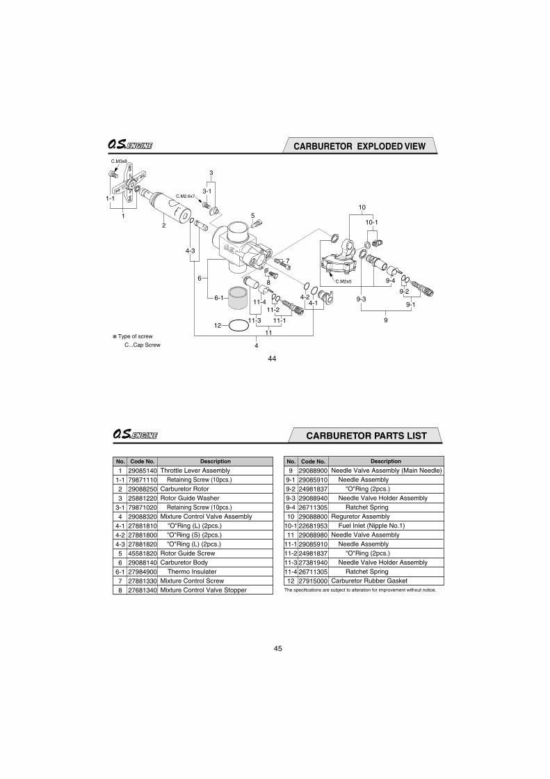
CARBURETOR PARTS LIST
No. DescriptionCode No. No. DescriptionCode No.
Throttle Lever Assembly Retaining Screw (10pcs.)Carburetor RotorRotor Guide Washer Retaining Screw (10pcs.)Mixture Control Valve Assembly "O"Ring (L) (2pcs.) "O"Ring (S) (2pcs.) "O"Ring (L) (2pcs.)Rotor Guide ScrewCarburetor Body Thermo InsulaterMixture Control ScrewMixture Control Valve Stopper
Needle Valve Assembly (Main Needle) Needle Assembly "O"Ring (2pcs.) Needle Valve Holder Assembly Ratchet SpringReguretor Assembly Fuel Inlet (Nipple No.1) Needle Valve Assembly Needle Assembly "O"Ring (2pcs.) Needle Valve Holder Assembly Ratchet SpringCarburetor Rubber Gasket
11-123
3-14
4-14-24-356
6-178
2908514079871110290882502588122079871020290883202788181027881800278818204558182029088140279849002788133027681340
99-19-29-39-410
10-111
11-111-211-311-412
29088900290859102498183729088940267113052908880022681953290889802908591024981837273819402671130527915000

46
(71531000)
(71531010)
(72403050) (55500003)
(71530510)
(71521000)(L)
91
M4
LONG SOCKET WRENCH WITH PLUG GRIP
SUPER FILTER LOCK WASHER(10set)
O.S. GENUINE PARTS & ACCESSORIES
The specifications are subject to alteration for improvement without notice.
GLOWPLUG CRANKSHAFT CLAMP
NON-BUBBLEWEIGHT
NON-BUBBLEWEIGHT
S
(71605100)
No.10(Former A5)
(71608001)No.8
(71607100)No.7
(72145020) (72145030)
(29122520) (72145010)
POWERBOOST PIPE 90
Silencer Retaining Screw(2pcs.)
Exhaust Tube
Exhaust Gasket Set(2pcs.)
Pressure Nipple M4
47
THREE VIEW DRAWING
Displacement Bore Stroke Practical R.P.M. Power output Weight
SPECIFICATIONS
Dimensions(mm)
14.95 cc (0.912 cu.in.)27.7 mm (1.091 in.)24.8 mm (0.976 in.)2,000~16,000 r.p.m.3.6 hp / 15,500 r.p.m.603 g (21.27 oz.)
42
42.8
27.4
UNF 5/16-24
88.756.4
12
79
JAPAN
25
52
4- 4.2
4361
42
JAPAN

48
MEMO
C Copyright 2011 by O.S.Engines Mfg. Co., Ltd. All rights reserved. Printed in Japan. 60092520 031100
TEL. (06) 6702-0225FAX. (06) 6704-2722
6-15 3-Chome Imagawa Higashisumiyoshi-ku Osaka 546-0003, Japan