Embed Size (px)
Citation preview

Model No.
TH-80LFB70W
Operating InstructionsTouch Screen LCD Display (for business use)
For more detailed instructions, refer to the Operating Instructions on the CD-ROM.
Contents• Important Safety Notice .............................2• Safety Precautions .....................................3• Accessories ................................................7• Connections ...............................................9• Power On / Off .........................................11• Basic Controls ..........................................13• Speci� cations ...........................................15
Please read these instructions before operating your set and retain them for future reference.English
TQB0AC0089

2
Important Safety Notice
WARNING1) To prevent damage which may result in � re or shock hazard, do not expose this appliance to dripping
or splashing. Do not place containers with water (� ower vase, cups, cosmetics, etc.) above the set. (including on
shelves above, etc.) No naked � ame sources, such as lighted candles, should be placed on / above the set. 2) To prevent electric shock, do not remove cover. No user serviceable parts inside. Refer servicing to quali� ed
service personnel.3) Do not remove the earthing pin on the power plug. This apparatus is equipped with a three pin earthing-type
power plug. This plug will only � t an earthing-type power outlet. This is a safety feature. If you are unable to insert the plug into the outlet, contact an electrician.
Do not defeat the purpose of the earthing plug.4) To prevent electric shock, ensure the earthing pin on the AC cord power plug is securely connected.
CAUTIONThis appliance is intended for use in environments which are relatively free of electromagnetic � elds.Using this appliance near sources of strong electromagnetic � elds or where electrical noise may overlap with the input signals could cause the picture and sound to wobble or cause interference such as noise to appear.To avoid the possibility of harm to this appliance, keep it away from sources of strong electromagnetic � elds.
Note:Image retention may occur. If you display a still picture for an extended period, the image might remain on the screen. However, it will disappear after a while.
IMPORTANT INFORMATIONIf a display is not positioned in a suf� ciently stable location, it can be potentially hazardous due to falling. Many injuries, particularly to children, can be avoided by taking simple precautions such as:• Using cabinets or stands recommended by the manufacturer of the display.• Only using furniture that can safely support the display.• Ensuring the display is not overhanging the edge of the supporting furniture.• Not placing the display on tall furniture (for example, cupboards or bookcases) without anchoring both the furniture
and the display to a suitable support.• Not standing the displays on cloth or other materials placed between the display and supporting furniture.• Educating children about the dangers of climbing on furniture to reach the display or its controls.
3
Safety Precautions
Always be sure to ask a quali� ed technician to carry out set-up.
Small parts can present choking hazard if accidentally swallowed. Keep small parts away from young children. Discard unneeded small parts and other objects, including packaging materials and plastic bags/sheets to prevent them from being played with by young children, creating the potential risk of suffocation.
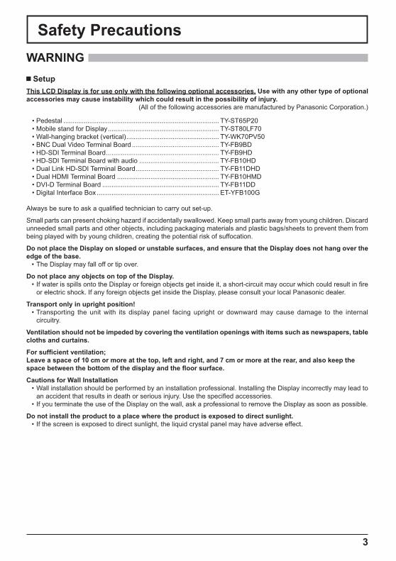
Do not place the Display on sloped or unstable surfaces, and ensure that the Display does not hang over the edge of the base.
• The Display may fall off or tip over.
Do not place any objects on top of the Display.• If water is spills onto the Display or foreign objects get inside it, a short-circuit may occur which could result in � re
or electric shock. If any foreign objects get inside the Display, please consult your local Panasonic dealer.
Transport only in upright position!• Transporting the unit with its display panel facing upright or downward may cause damage to the internal
circuitry.
Ventilation should not be impeded by covering the ventilation openings with items such as newspapers, table cloths and curtains.
For suf� cient ventilation;Leave a space of 10 cm or more at the top, left and right, and 7 cm or more at the rear, and also keep the space between the bottom of the display and the � oor surface.
Cautions for Wall Installation• Wall installation should be performed by an installation professional. Installing the Display incorrectly may lead to
an accident that results in death or serious injury. Use the speci� ed accessories.• If you terminate the use of the Display on the wall, ask a professional to remove the Display as soon as possible.
Do not install the product to a place where the product is exposed to direct sunlight.• If the screen is exposed to direct sunlight, the liquid crystal panel may have adverse effect.
WARNING Setup
This LCD Display is for use only with the following optional accessories. Use with any other type of optional accessories may cause instability which could result in the possibility of injury.
(All of the following accessories are manufactured by Panasonic Corporation.)
• Pedestal .................................................................................... TY-ST65P20• Mobile stand for Display ............................................................ TY-ST80LF70• Wall-hanging bracket (vertical) .................................................. TY-WK70PV50• BNC Dual Video Terminal Board ............................................... TY-FB9BD• HD-SDI Terminal Board ............................................................. TY-FB9HD• HD-SDI Terminal Board with audio ........................................... TY-FB10HD• Dual Link HD-SDI Terminal Board ............................................. TY-FB11DHD• Dual HDMI Terminal Board ....................................................... TY-FB10HMD• DVI-D Terminal Board ............................................................... TY-FB11DD• Digital Interface Box .................................................................. ET-YFB100G

4
Safety Precautions
When using the LCD Display
The Display is designed to operate on 220 - 240 V AC, 50/60 Hz.
Do not cover the ventilation holes.• Doing so may cause the Display to overheat, which can cause � re or damage to the Display.
Do not stick any foreign objects into the Display.• Do not insert any metal or � ammable objects into the ventilations holes or drop them onto the Display, as doing so
can cause � re or electric shock.
Do not remove the cover or modify it in any way.• High voltages which can cause severe electric shocks are present inside the Display. For any inspection, adjustment
and repair work, please contact your local Panasonic dealer.
Ensure that the mains plug is easily accessible.
An apparatus with CLASS I construction shall be connected to a mains socket outlet with a protective earthing connection.
Do not use any power supply cord other than that provided with this unit.• Doing so may cause � re or electric shocks.
Securely insert the power supply plug as far as it will go.• If the plug is not fully inserted, heat may be generated which could cause � re. If the plug is damaged or the wall
socket is loose, they shall not be used.
Do not handle the power supply plug with wet hands.• Doing so may cause electric shocks.
Do not do anything that may damage the power cable. When disconnecting the power cable, pull on the plug body, not the cable.
• Do not damage the cable, make any modi� cations to it, place heavy objects on top of it, heat it, place it near any hot objects, twist it, bend it excessively or pull it. To do so may cause � re and electric shock. If the power cable is damaged, have it repaired at your local Panasonic dealer.
Do not remove covers and NEVER modify the Display yourself• Do not remove the rear cover as live parts are accessible when it is removed. There are no user serviceable parts
inside. (High-voltage components may cause serious electrical shock.) • Have the Display checked, adjusted, or repaired at your local Panasonic dealer.
Keep the Pen Stand � xing screw and washer out of reach of children to prevent swallowing.
If the Display is not going to be used for any prolonged length of time, unplug the power supply plug from the wall outlet.
To prevent the spread of � re, keep candles or other open � ames away from this product at all times.
If problems occur during use
If a problem occurs (such as no picture or no sound), or if smoke or an abnormal odour starts to come out from the Display, immediately unplug the power supply plug from the wall outlet.
• If you continue to use the Display in this condition, � re or electric shock could result. After checking that the smoke has stopped, contact your local Panasonic dealer so that the necessary repairs can be made. Repairing the Display yourself is extremely dangerous, and shall never be done.
If water or foreign objects get inside the Display, if the Display is dropped, or if the cabinet becomes damages, disconnect the power supply plug immediately.
• A short circuit may occur, which could cause � re. Contact your local Panasonic dealer for any repairs that need to be made.

5
Safety Precautions
CAUTION When using the LCD Display
Do not bring your hands, face or objects close to the ventilation holes of the Display.• Heated air comes out from the ventilation holes at the top of Display will be hot. Do not bring your hands or face,
or objects which cannot withstand heat, close to this port, otherwise burns or deformation could result.
Be sure to disconnect all cables before moving the Display.• If the Display is moved while some of the cables are still connected, the cables may become damaged, and � re or
electric shock could result.
Disconnect the power supply plug from the wall socket as a safety precaution before carrying out any cleaning.
• Electric shocks can result if this is not done.
Clean the power cable regularly to prevent it becoming dusty.• If dust built up on the power cord plug, the resultant humidity can damage the insulation, which could result in � re.
Pull the power cord plug out from the wall outlet and wipe the mains lead with a dry cloth.
Do not burn or breakup batteries.• Batteries must not be exposed to excessive heat such as sunshine, � re or the like.
Cleaning and maintenanceThe front of the display panel has been specially treated. Wipe the panel surface gently using only a cleaning cloth or a soft, lint-free cloth.
• If the surface is particularly dirty, wipe with a soft, lint-free cloth which has been soaked in pure water or water in which neutral detergent has been diluted 100 times, and then wipe it evenly with a dry cloth of the same type until the surface is dry.
• Do not scratch or hit the surface of the panel with � ngernails or other hard objects, otherwise the surface may become damaged. Furthermore, avoid contact with volatile substances such as insect sprays, solvents and thinner, otherwise the quality of the surface may be adversely affected.
If the cabinet becomes dirty, wipe it with a soft, dry cloth.• If the cabinet is particularly dirty, soak the cloth in water to which a small amount of neutral detergent has been
added and then wring the cloth dry. Use this cloth to wipe the cabinet, and then wipe it dry with a dry cloth.• Do not allow any detergent to come into direct contact with the surface of the Display. If water droplets get inside
the unit, operating problems may result.• Avoid contact with volatile substances such as insect sprays, solvents and thinner, otherwise the quality of the
cabinet surface may be adversely affected or the coating may peel off. Furthermore, do not leave it for long periods in contact with articles made from rubber or PVC.
Wipe off dirt on the IR transmission part with soft cloth.• Wipe off dirt on the IR transmission part with soft cloth once a day.
If malfunction is due to dirt on the IR transmission part, simply wiping it off lightly can recover the performance.If dirt is sticky, wipe it off with cloth wrung out of neutral detergent diluted with water and then wipe the part with dry cloth.
Usage of a chemical cloth• Do not use a chemical cloth for the panel surface.• Follow the instructions for the chemical cloth to use it for the cabinet.
Ask your dealer to clean the inside at least once a year.• Dust accumulated inside may interfere with the infrared beam for touch detection, resulting in poor performance.
Ask your dealer to clean the inside at least once a year.
6
Safety Precautions
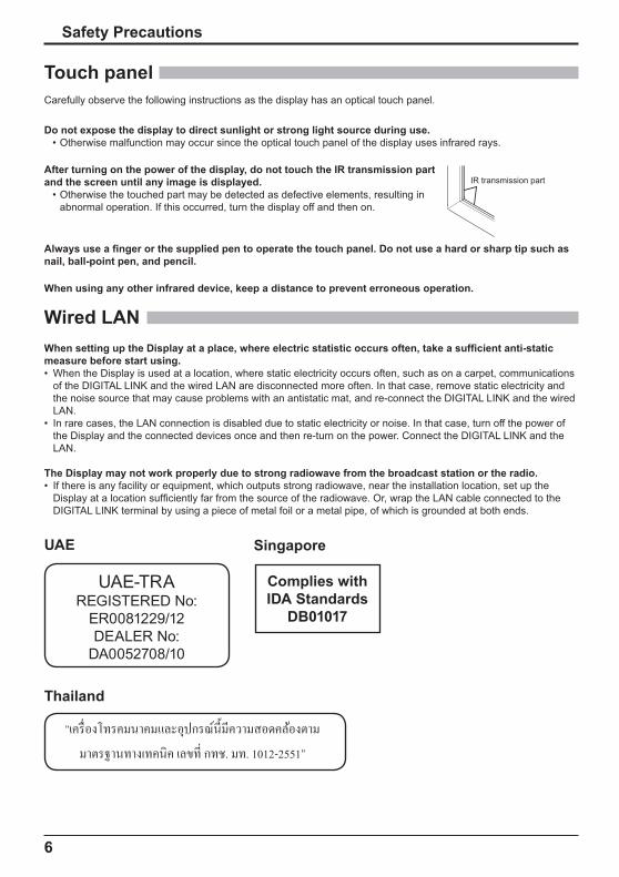
Touch panelCarefully observe the following instructions as the display has an optical touch panel.
Do not expose the display to direct sunlight or strong light source during use.• Otherwise malfunction may occur since the optical touch panel of the display uses infrared rays.
After turning on the power of the display, do not touch the IR transmission part and the screen until any image is displayed.
• Otherwise the touched part may be detected as defective elements, resulting in abnormal operation. If this occurred, turn the display off and then on.
Always use a � nger or the supplied pen to operate the touch panel. Do not use a hard or sharp tip such as nail, ball-point pen, and pencil.
When using any other infrared device, keep a distance to prevent erroneous operation.
Wired LANWhen setting up the Display at a place, where electric statistic occurs often, take a suf� cient anti-static measure before start using.• When the Display is used at a location, where static electricity occurs often, such as on a carpet, communications
of the DIGITAL LINK and the wired LAN are disconnected more often. In that case, remove static electricity and the noise source that may cause problems with an antistatic mat, and re-connect the DIGITAL LINK and the wired LAN.
• In rare cases, the LAN connection is disabled due to static electricity or noise. In that case, turn off the power of the Display and the connected devices once and then re-turn on the power. Connect the DIGITAL LINK and the LAN.
The Display may not work properly due to strong radiowave from the broadcast station or the radio.• If there is any facility or equipment, which outputs strong radiowave, near the installation location, set up the
Display at a location suf� ciently far from the source of the radiowave. Or, wrap the LAN cable connected to the DIGITAL LINK terminal by using a piece of metal foil or a metal pipe, of which is grounded at both ends.
IR transmission part
UAE
UAE-TRAREGISTERED No:
ER0081229/12DEALER No:
DA0052708/10
Thailand
Singapore
Complies withIDA Standards
DB01017
“����������� ������������������� ���������� � � ��� � ������ ����� �!. �. 1012-2551”
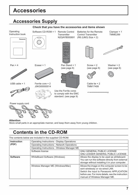
Clamper × 1TMME289
Batteries for the Remote Control Transmitter(R6 (UM3) Size × 2)
Remote Control TransmitterN2QAYB000691
Operating Instruction book
Check that you have the accessories and items shownSoftware CD-ROM × 1
Pen × 4 Eraser × 1 Pen Stand × 1(see page 8)
Screw × 2 (see page 8)
Washer × 2 (see page 8)
USB cable × 1 Ferrite core × 2J0KG00000014
Cable tie × 2TMM17499
Power supply cord
7
Accessories Supply
Accessories
Contents in the CD-ROMThe contents below are included in the supplied CD-ROM.Instruction (PDF)
Operating Instructions - Display OperationsOperating Instructions - Network OperationsOperating Instructions - Wireless Manager MESoftware license GNU GENERAL PUBLIC LICENSE
GNU LESSER GENERAL PUBLIC LICENSESoftware WhiteBoard Software (Windows) Allows the display to be used as whiteboard.
You can run the software directly from external storage without installing it in your computer.
Wireless Manager ME (Windows/Mac) Allows the image on the computer screen to be sent wirelessly or via wired LAN.Switch the input to Panasonic APPLICATION before use. For more details, see the instruction manual of Wireless Manager ME.
AttentionStore small parts in an appropriate manner, and keep them away from young children.
Use the Ferrite cores to comply with the EMC standard. (see page 9)
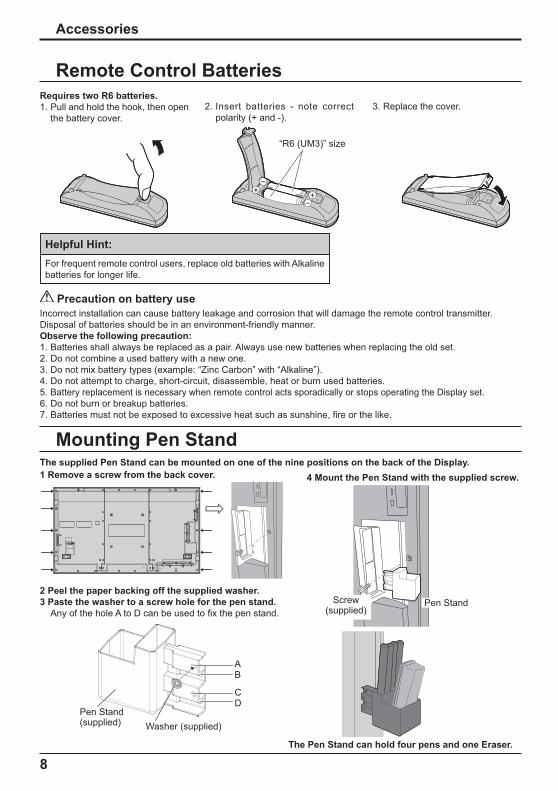
1 Remove a screw from the back cover. 4 Mount the Pen Stand with the supplied screw.
The Pen Stand can hold four pens and one Eraser.
2 Peel the paper backing off the supplied washer.3 Paste the washer to a screw hole for the pen stand.
Any of the hole A to D can be used to � x the pen stand.
AB
CD
Washer (supplied)Pen Stand (supplied)
Screw(supplied)
Pen Stand
8
+-
+
-
Remote Control BatteriesRequires two R6 batteries.1. Pull and hold the hook, then open
the battery cover.2. Insert batteries - note correct
polarity (+ and -).3. Replace the cover.
Helpful Hint:For frequent remote control users, replace old batteries with Alkaline batteries for longer life.
Precaution on battery useIncorrect installation can cause battery leakage and corrosion that will damage the remote control transmitter.Disposal of batteries should be in an environment-friendly manner.Observe the following precaution:1. Batteries shall always be replaced as a pair. Always use new batteries when replacing the old set.2. Do not combine a used battery with a new one.3. Do not mix battery types (example: “Zinc Carbon” with “Alkaline”).4. Do not attempt to charge, short-circuit, disassemble, heat or burn used batteries.5. Battery replacement is necessary when remote control acts sporadically or stops operating the Display set.6. Do not burn or breakup batteries.7. Batteries must not be exposed to excessive heat such as sunshine, � re or the like.
“R6 (UM3)” size
Accessories
Mounting Pen StandThe supplied Pen Stand can be mounted on one of the nine positions on the back of the Display.

9
Connections
Plug the AC cord into the display unit.Plug the AC cord until it clicks.Note:Make sure that the AC cord is locked on both the left and right sides.
AC cord � xing
Unplug the AC cord
Unplug the AC cord pressing the two knobs.Note:When disconnecting the AC cord, be absolutely sure to disconnect the AC cord plug at the socket outlet � rst.
Using the clamperSecure any excess cables with clamper as required.Note:One clamper is supplied with this unit. In case of securing cables at four positions, please purchase it separately.If you need more clampers, purchase them from your dealer. (Available from the customer service)
1 2Attach the clamper To remove from the unit:
Keep pushing both side snaps
hole
Bundle the cables
snaps
hooksSet thetip in thehooks
To loosen:
Keeppushingthe knob
knobInsert the clamper in a hole.
AC cord connection and � xing, cable � xing
How to use the Ferrite core
Stereo mini plug (M3)
PC with DVI-D video out Shared with PC IN.
Less than 5 cm
Ferrite core (supplied)
DVI-video cable (Within 5 m)
Less than 5 cm
Installing the Ferrite core
Pull back the tabs(in two places)
1 .
Open the Ferrite core
2.
Route the cable through and close
3.
Fix the Ferrite core with the cable tie
4.

10
Video equipment connection
Connections
Please use 8 �/10 W speaker.
Speaker connection
RedBlack
RedBlack
1 While pressing the lever, insert the core wire.
2 Return the lever.
AUDIO 1 IN: Audio input terminal shared with VIDEO and COMPONENT/RGB IN.
PC IN: PC Input Terminal Connect to video terminal of PC or equipment with Y, PB(CB) and PR(CR) output.
DVI-D IN: DVI-D Input Terminal
LAN, DIGITAL LINK*Connect to a DIGITAL LINK input terminal network to control the Display. Alternatively, connect to a device that sends video and audio signals via the DIGITAL LINK terminal.
SERIAL: Serial Control Terminal. Control the Display by connecting to PC.
AV IN (VIDEO): Composite Video Input TerminalCOMPONENT/RGB IN: Component/RGB Video
Input Terminal
* DIGITAL LINK is technology that enables signals such as audio and video to be transmitted using twisted pair cables. For details, see the Operating Instructions - “Network Operations”.
AV IN (HDMI 1, HDMI 2): HDMI Input TerminalConnect to video equipment such as VCR or DVD player.
AUDIO 2 IN: Audio input terminal shared with DVI-D IN and PC IN.
PC OUT:Video signals being reproduced on the display are output to another sub monitor as PC video signals.
SLOT: Terminal board (optional accessories) insert slot (see page 3)
Note:The upper side slot is for terminal board with 2-slot width. The terminal board with 1-slot width does not function when installed in the upper side slot.

11
Power On / Off
Press the button on the remote control to turn the Display off.
Power Indicator: Red (standby)
Press the button on the remote control to turn the Display on.
Power Indicator: Green
Turn the power to the Display off by pressing the switch on the unit, when the Display is on or in standby mode.
Note: During operation of the power management function, the power indicator turns orange in the power off state.
Connecting the plug to the Wall Outlet
Notes:• Main plug types vary between countries. The power
plug shown at right may, therefore, not be the type � tted to your set.
• When disconnecting the AC cord, be absolutely sure to disconnect the AC cord plug at the socket outlet � rst.
Press the Power switch on the Display to turn the set on: Power-On.
Power Indicator: Green
[Starting up the touch screen and network]It takes some time for the touch screen and network to start up just after the power is turned on.During that time, “Touch Screen Settings”, “Network Settings” in the “Setup” menu is grayed out and cannot be set.
Connecting the AC cord plug to the Display.
Power switch
Power Indicator Remote Control Sensor

Set
Day MON
18:00Time
Day/Time Settings
Time MON 99:99
Set
Day TUE
18:00Time
Day/Time Settings
Time TUE 99:99
OSD Language
English (UK)
Deutsch
FrançaisItalianoEspañol
ENGLISH (US)
�����
12
Power On / Off
When � rst switching on the unitFollowing screen will be displayed when the unit is turned on for the � rst time.Use the remote control to make the settings. Pressing the buttons on the main unit or multi-touch operation will not work.
Notes:• Once the items are set, the screens won't be displayed when switching on the unit next time.• After the setting, the items can be changed in the following menus. OSD Language Day/Time Settings
Power ON messageThe following message may be displayed when turning the unit power ON:
No activity power off Precautions‘No activity power off’ is enabled.
If “No activity power off” in Setup menu is set to “Enable”, a warning message is displayed every time the power is turned ON.
Power Management InformationLast turn off due to ‘Power management’.
If “Power management” is functioned, an information message is displayed every time the power is turned ON. These message displays can be set with the following menu: Options menu
Power On Message (No activity power off) Power On Message (Power Management)
OSD Language Day/Time Settings
1 Select the language.
2 Set.
1 Select “Day” or “Time”.
2 Setup “Day” or “Time”.
1 Select “Set”.
2 Set.
WhiteBoard Startup screen
Now Loading...
WhiteBoard
When the power is turned ON with the Input switch of the WHITEBOARD, the built-in WhiteBoard starts up.
Touch screen connection status displayWhen not connected to a computer via USB
Initializing Touch Screen...
When connected to a computer via USBTouch Screen connected to external device.
Touch Screen detected.
Touch operation of the display is possible after this message appears.

13
INPUT
MENU
VOL
ENTER/
+ /
- /
Basic Controls
MENU Screen ON / OFFEach time the MENU button is pressed, the menu screen will switch.
Normal Viewing PictureSound Pos. /Size Setup
Volume AdjustmentVolume Up “+” Down “–” When the menu screen is displayed:“+” : press to move the cursor up “–” : press to move the cursor down
Remote control sensor
Main Power On / Off Switch
Brightness SensorDetects the brightness in the viewing environment.
Main Unit Power IndicatorThe Power Indicator will light.• Power-OFF .... Indicator not illuminated (The unit will still
consume some power as long as the power cord is still inserted into the wall outlet.)
• Standby ........ RedOrange (When “Slot power” is set to “On” and Terminal Board is installed.)Orange (Depending on the type of the function board installed, when the power is supplied to the slot)Orange (When “Control I/F Select” is set to “DIGITAL LINK/LAN” or “Wireless Network Standby” is set to “On”. Refer to “Operating Instructions, Network Operations”)Orange (When “Quick Launch” is set to “On”.)
• Power-ON ...... Green• HDMI1 Power management
HDMI2 Power management......................... Orange (With HDMI1 or HDMI2 input signal.)• PC Power management (DPMS) ......................... Orange (With PC input signal.)• DVI-D Power management ......................... Orange (With DVI input signal.)Note:If the power indicator is orange, power consumption during standby is generally larger than that of when the power indicator is red.
Enter / Aspect button
INPUT button (INPUT signal selection)
SLOT: Terminal board (optional accessories) insert slot (see page 3)
Note:The upper side slot is for terminal board with 2-slot width. The terminal board with 1-slot width does not function when installed in the upper side slot.
Touch panel IR transmission partInstalled on the four sides of the display panel.
USB (VIEWER): Connect to USB memory.USB (TOUCH): When using the “WhiteBoard
Software” from the supplied CD-ROM, connect the computer via USB cable.

14
Basic Controls
Remote Control Transmitter
Digital Zoom
1
2
PC4:3
� COMPONENTMemory name: MEMORY2
Off timer 90min 34 10:00
Standby (ON / OFF) buttonThe Display must � rst be plugged into the wall outlet and turned on at the power switch (see page 11).Press this button to turn the Display On, from Standby mode. Press it again to turn the Display Off to Standby mode.
ACTION buttonPress to make selections.
ASPECT buttonPress to adjust the aspect.
POS./SIZE button
PICTURE button
Sound mute On / Off Press this button to mute the sound.Press again to reactivate sound.Sound is also reactivated when power is turned off or volume level is changed.
N button
POSITION buttons
INPUT button Press to select Input signal sequentially.
ECO MODE (ECO)Press to change the ECO MODE setup status.
FUNCTION buttons (FUNCTION)
AUTO SETUP buttonAutomatically adjusts the position/size of the screen.
SET UP button
SOUND button
Volume AdjustmentPress the Volume Up “+” or Down “–” button to increase or decrease the sound volume level.
R button Press the R button to return to previous menu screen.
OFF TIMER buttonThe Display can be preset to switch to stand-by after a � xed period. The setting changes to 30 minutes, 60 minutes, 90 minutes and 0 minutes (off timer cancelled) each time the button is pressed.
30 min 60 min0 min (Cancel)
90 min
When three minutes remain, “Off timer 3 min” will � ash.The off timer is cancelled if a power interruption occurs.
RECALL buttonPress the “RECALL” button to display the current system status.1 Input label2 Aspect mode Audio input Pro� le name3 Off timer The off timer indicator is
displayed only when the off timer has been set.
4 Clock display
15
Speci� cationsTH-80LFB70W
Power Source 220 - 240 V AC, 50/60 HzPower Consumption
Power on 350 WStand-by condition 0.5 WPower off condition 0.3 W
LCD Display panel 80-inch VA panel (LED backlight), 16:9 aspect ratioScreen size 1,771 mm (W) × 996 mm (H) × 2,032 mm (diagonal)
(No.of pixels) 2,073,600 (1,920 (W) ×1,080 (H))[5,760 × 1,080 dots]
Operating conditionTemperature 0 °C - 40 °C
Humidity 20 % - 80 % (no condensation) Applicable signals
Colour System NTSC, PAL, PAL60, SECAM, Modi� ed NTSCScanning format 525 (480) / 60i · 60p, 625 (575) / 50i · 50p, 750 (720) / 60p · 50p, 1125 (1080) / 60i · 60p · 50i ·
50p · 24p · 25p · 30p · 24psF, 1250 (1080) / 50i PC signals VGA, SVGA, XGA, SXGA
UXGA ···· (compressed)Horizontal scanning frequency 15 - 110 kHz
Vertical scanning frequency 48 - 120 HzConnection terminals
AV IN VIDEOAUDIO 1 IN
BNCStereo mini jack (M3) × 1
1.0 Vp-p (75 �)0.5 Vrms, Shared with COMPONENT/RGB IN
HDMI 1HDMI 2
TYPE A Connector × 2
COMPONENT/RGB INY/G
PB/CB/BPR/CR/R
AUDIO 1 IN
BNCBNCBNCStereo mini jack (M3) × 1
with sync 1.0 Vp-p (75 �)0.7 Vp-p (75 �)0.7 Vp-p (75 �)0.5 Vrms, Shared with VIDEO
DVI-D IN
AUDIO 2 IN
DVI-D 24 PinContent ProtectionStereo mini jack (M3) × 1
Compliance with DVI Revision 1.0Compatible with HDCP 1.10.5 Vrms, Shared with PC IN
PC IN
AUDIO 2 IN
High-Density Mini D-sub 15 Pin
Stereo mini jack (M3) × 1
Y or G with sync 1.0 Vp-p (75 �)Y or G without sync 0.7 Vp-p (75 �)PB/CB/B: 0.7 Vp-p (75 �)PR/CR/R: 0.7 Vp-p (75 �)HD/VD: 1.0 - 5.0 Vp-p (high impedance)0.5 Vrms, Shared with DVI-D IN
SERIAL External Control TerminalD-sub 9 Pin RS-232C compatible
PC OUT R: 0.7 Vp-p (75 �)G: 0.7 Vp-p (75 �)B: 0.7 Vp-p (75 �)HD/VD: 1.0 - 5.0 Vp-p
USB (VIEWER) TYPE A USB connectorUSB (TOUCH) TYPE B USB connector
DIGITAL LINK / LAN For RJ45 network and DIGITAL LINK connections, compatible with PJLink™Communication method: RJ45 100BASE-TX
EXT SP 8 �, 20 W [10 W + 10 W] (10 % THD)Sound
Speakers 120 mm × 40 mm × 2 pcsAudio Output 20 W [10 W + 10 W] (10 % THD)
Dimensions (W × H × D) 1,868 mm × 1,093 mm × 104 mmMass (weight) approx. 84.0 kg net
Note:Design and speci� cations are subject to change without notice. Mass and dimensions shown are approximate.

Customer’s RecordThe model number and serial number of this product can be found on its rear panel. You should note this serial number in the space provided below and retain this book, plus your purchase receipt, as a permanent record of your purchase to aid in identi� cation in the event of theft or loss, and for Warranty Service purposes.
Model Number Serial Number
Web Site : http://panasonic.net� Panasonic Corporation 2014
Printed in China
Trademark Credits• VGA is a trademark of International Business Machines Corporation.• Microsoft®, Windows®, Windows Vista®, and Internet Explorer® are the registered trademarks or trademarks of
Microsoft Corporation in the United States and/or other countries.• Macintosh, Mac, Mac OS, OS X and Safari are the trademarks of Apple Inc. registered in the United States
and other countries.• SVGA, XGA, SXGA and UXGA are registered trademarks of the Video Electronics Standard Association.
Even if no special notation has been made of company or product trademarks, these trademarks have been fully respected.
• HDMI, the HDMI Logo, and High-De� nition Multimedia Interface are trademarks or registered trademarks of HDMI Licensing LLC in the United States and other countries.
• RoomView, Crestron RoomView and Fusion RV are registered trademarks of Crestron Electronics, Inc, and Crestron Connected is the trademark of Crestron Electronics, Inc.
• Miracast is a trademark of Wi-Fi Alliance.• Android is a registered trademark of Google Inc.• iPad, iPhone, and iPod touch are trademarks of Apple Inc., registered in the U.S. and other countries.