Embed Size (px)
Citation preview

Contemporary Implant Dentistry
Edwin A. McGlumphy and Peter E. Larsen
CHAPTER OUTLINE
BIOLOGIC CONSIDERATIONS FOR OSSEOINTEGRATION SoftTissue-to-lmplant Interface
Biomechanical Factors Affecting Long-Term Implant Success
CLINICAL IMPLANT COMPONENTS Implant Cover Screw Healing Cap Abutment Impression Post Laboratory Analog Waxing Sleeve Prosthesis-Retaining Screw IMPLANT PROSTHETIC OPTIONS Completely Edentulous Patients Implant- and Tissue-Supported Overdenture All Implant-Supported Overdenture Fixed Detachable Restoration Partially Edentulous Patients Free-End Distal Extension Single-Tooth Implant Restorations PREOPERATIVE MEDICAL EVALUATION OF IMPLANT
PATIENT SURGICAL PHASE: TREATMENT PLANNING
Evaluation of Implant Site Bone Height, Width, and Anatomic Limitations
Informed Consent Surgical Guide Template
BASIC SURGICAL TECHNIQUES Patient Preparation Soft Tissue Incision Preparation of Implant Site Implant Placement Postoperative Care Uncovering
COMPLICATIONS Failing Implant
ADVANCED SURGICALTECHNIQUES Guided Bone Regeneration Block Bone Grafting Alveolar Distraction Transantral Grafting (Sinus Lift)
SPECIAL SITUATIONS Postextraction Placement of Implants Anterior Maxilla Esthetic Zone Atrophic Anterior Mandible Atrophic Posterior Mandible Atrophic Maxilla Implants in Growing Patients Implants in Irradiated Bone Early Loading Extraoral Implants
305

pat
he dental professional must use considerable clinical skill to help
ients cope with the effects of partial or complete edentulism.
Dental problems that were historically the most difficult can be solved today with the assistance of dental implants. Completely edentulous patients now enjoy the security and function of fixed restorations (Fig. 14-1). Patients missing a posterior abutment, who would ordinarily require a distal extension removable partial denture, may now enjoy the benefits of a fixed restoration with dental implants (Fig. 14-2). Trauma victims who are missing teeth and bone can be successfully rehabilitated with fixed restorations (Fig. 14-3). Even the patient missing only a single tooth can receive a restoration more analogous to the missing natural tooth (Fig. 14-4). Likewise, a patient with the available bone can receive a complete fixed implant rehabilitation (Fig. 14-5). These examples illustrate advantageous and predictable alternatives to edentulism that are becoming the standard of care within the dental community.
The dental profession has not always had a positive opinion of dental implants. Implants had their begin-nings around the middle of the twentieth century. Early types of dental implants came into relatively common use during the 1960s because of patient demand,
although little or no scientifically sound research had been done to characterize implant success rates.
In a May 1982 conference held in Toronto, the North American dental profession was introduced to a body of scientific literature on Swedish research into the bone-to-implant interface—a concept called osseointegration. This] new concept is based on atraumatic implant placement and delayed implant loading. These factors contribute to a remarkably higher degree of implant predictably than was previously possible. The Swedish research team led by P. I. Branemark reported high success in the mandible for over 15 years. The knowledge gained from the experience of the Swedish team was used in the development of other systems currently available on the market. Today the American Dental Association (ADA) has also accepted many other systems.
In 1988 a National Institutes of Health (NIH) consen-sus conference was held in Washington, D.C. This con-ference evaluated the long-term effectiveness of dental implants and established indications and contraindica-tions for the various types of dental implants. Stringent criteria for success were proposed and have gained gener-al acceptance (Box 14-1). By these criteria a success rate of 85% at the end of a 5-year observation period and 80% at the end of a 10-year period are minimal levels for success.
FIG. 14-1 Complete-arch implant restoration supported by five implants in completely edentulous patient.
FIG. 14-2 Radiograph of two-unit implant restoration used to restore dentition. Conventionally, replacement with removable par-tial denture would be required.
FIG. 14-3 A, Twenty-six-year-old patient with large dental defect caused by shotgun wound. Three implants placed in defect. B,Trau-matic defect restored with implant-supported hybrid restoration retained by screws.

Single dental implant has been placed in extraction site. Abutment projects through soft tissue. B, Single-tooth implant restored without compromising adjacent tooth structure.
FIG. 14-5 Radiograph of complete-mouth fixed implant restoration.
BIOLOGIC CONSIDERATIONS FOR OSSEOINTEGRATION FOR OSSEOINTEGRATION The recent success of dental implants relates directly to the discovery of methods to maximize the amount of bone and implant contact. Osseointegration is a histo-logic definition meaning "a direct connection between living bone and load-bearing endosseous implant at the light microscopic level." Four main factors are required to achieve a successful osseointegrated bone-to-implant interface: (1) a biocompatible material, (2) an implant precisely adapted to the prepared bony site, (3) atraumat-ic surgery to minimize tissue damage, and (4) an immo-bile, undisturbed healing phase. A biocompatible materi-al is necessary to promote healing without a foreign-body rejection reaction by the host tissue. If biocompatible materials are not used, the body attempts to isolate the foreign-body implant material by surrounding it with granulation and then connective tissue. It has been
demonstrated that titanium and certain calcium-phos-phate ceramics are both biologically inert.
The size of the gap between the implant and the bone immediately after implant placement is critical to achieving osseointegration. The gap size can be controlled primarily by the preparation of a precise surgical bed into which the implant is placed. Cylindrical preparations are the most predictably made in an accurate shape. Precision instru-mentation and a technically sound surgical procedure min-imize the distance between the implant and host bone.
Atraumatic surgery is required to allow minimal mechanical and thermal injury to occur. Sharp, high-quality burs that are run at low speed by high-torque drills are essential to precise atraumatic bed preparation, Copious irrigation by either internal or external methods keeps the bone temperatures to levels below 56° C, which is the level beyond which irreversible bone damage occurs. It has been also found that bone tissue damage occurs when the bone temperature reaches 47° C for more than 1 minute. If the temperature rises, alkaline phosphatase within the bone is denatured, which pre-vents alkaline calcium synthesis. If the gap between the implant and the bone can be minimized and surgery is atraumatic, embryonic bone will rapidly be laid down between the implant and the bone and will then mature into the lamellar load-bearing bone (Fig. 14-6).
Implant immobility during the healing phase is affect-ed by bone quality and quantity.
Areas of the jaws that have a high percentage of corti-cal bone, such as the anterior mandible, are more likely to anchor the implant successfully. Areas of the jaws with a high percentage of cancellous bone make initial stability for the implant more difficult to achieve. It is also advantageous for initial implant stability if both the superior and inferior cortical plates can be used to stabi-lize the implant (Fig. 14-7), which is frequently possible in the anterior mandible and the maxilla. However, the
From Smith D, Zarb CA: Criteria for success for osseointegrated endosseous implants, J Prosthet Dent 62:567, 1989.
inferior alveolar canal prevents this from occurring in the posterior mandible.
FIG. 14-6 A, Implant site prepared in bone using irrigation to keep temperatures below 47° C to pre-vent cell death in area. B, Precisely machined implant placed in site. Cap between implant and bone should be less than 1 mm. C, If gap between implant and bone is small enough, embryonic bone will rapidly bridge gap. D, If implant is left undisturbed during healing phase, embryonic bone will mature to lamellar load-bearing bone.

Once the initial stability of the implant has been achieved, it must be maintained throughout the healing-phase. Should the patient desire to continue to wear the removable prosthesis during the healing period, it is important that a soft liner be placed in the removable den-ture to further decrease load transfer to the implant. The bone in the mandible is generally denser than the bone in the maxilla. Therefore because the maxilla is primarily cancellous bone, osseointegration requires a longer heal-ing period. When placing implants, it is crucial to obtain primary stabilization for successful osseointegration.
The achievement of successful osseointegration is first assessed at the second surgery. Once the abutment is attached to the implant body, the surgeon should care-fully check for any signs of clinically detectable mobility. An immobile implant at this stage indicates successful osseointegration. Detectable mobility at this stage indi-cates that fibrous connective tissue has encapsulated the implant. If mobility is detected, the implant should be removed at that time. The failed site is allowed to heal and another implant can be placed at a later time. Once a successful osseointegrated bone-to-implant interface has been achieved, masticatory function at least equal that of natural dentition is generally possible.
The major mechanisms for the destruction of osseoin-tegration are similar to those of natural teeth. Disease activity in the periimplant soft tissue environment and biomechanical overload of the individual implant are the two factors most commonly associated with the potential breakdown of osseointegration.
Soft Tissue-to-lmplant Interface The successful dental implant should have an unbroken, perimucosal seal between the soft tissue and the implant abutment surface. To maintain the integrity of this seal, the patient must maintain a high level of oral hygiene
specific to dental implants. Clinicians, dental hygienists, and patients must understand and appreciate the necessi-ty for a comprehensive implant maintenance program, including regularly scheduled recall visits. In the natural dentition the junctional epithelium provides a seal at the base of the gingival sulcus against the penetration of chemical and bacterial substances. It has been demon-strated that epithelial cells attach to the surface of titani-um in much the same manner in which the epithelial cells attach to the surface of the natural tooth, that is, through a basal lamina and by the formation of hemidesmosomes. The connection differs from that occurring with natural teeth at the connective tissue attachment level. In the natural dentition, Sharpey's fibers extend from the bundle bone of the lamina dura and insert into the cementum of the tooth root surface. Because no cementum or fiber insertion is found on the surface of an endosseous implant, the epithelial surface attachment is all-important. If this seal is lost, the peri-odontal pocket can extend directly to the osseous struc-tures. Therefore if the seal breaks down or is not present, the area is subject to periimplant gingival disease.
Although the abutment-to-junctional epithelium attachment is not mechanically strong, it is adequate to resist bacterial invasion with the assistance of adequate home care. When implants are stable and they have a highly polished titanium collar transversing the tissue, gingival and periimplant health appear relatively easy to maintain. The lack of definitive gingival connective tissue attachment appears to be less of a problem in osseointe-grated implants than it was in implants with fibrous connective tissue attachments. Because osseointegrated implants have a different relationship between the implant and bone, there appears to be different mecha-nisms working against inflammation caused by bacteria and their by-products. The pathogenicity of the bacteria seems to be particularly diminished in the completely edentulous patient restored with dental implants. Disease activity around the natural dentition in the partially edentulous patient may contribute to a slightly higher incidence of periimplant disease in these patients.
Implant survival depends on proper and timely home care and maintenance. The dentist must ensure that the patient receives thorough instruction in maintenance techniques. The goal of implant maintenance is to eradi-cate microbial populations. Recall visits should be sched-uled at least every 3 months for the first year. The sulcu-Iar area should be debrided of calculus by using plastic or wooden scalers. A rubber cup with low abrasive polishing paste or tin oxide may be used to polish implant abut-ments. Implant mobility should be evaluated and bleed-ing upon probing documented. Framework fit and occlu-sion should also be checked at recall appointments. These biomechanical factors are as important as oral hygiene for the long-term success of the dental implant.
Biomechanical Factors Affecting Long-Term Implant Success Bone resorption around dental implants can be caused by
premature loading or repeated overloading. Vertical or angular bone loss is usually characteristic of bone resorp- FIG. 14-7 Initial implant stability can be aided if implant canengage two cortical plates of bone.

FIG. 14-8 Implants positioned outside of arch form may lead to individual fixture overload.
tion caused by occlusal trauma. When pressure from trau-matic occlusion is concentrated, bone resorption occurs by osteoclastic activity. In the natural dentition, bone reposition would typically occur once the severe stress concentration is reduced or eliminated. However, in the osseointegrated implant system, after bone resorbs, it will not usually reform. Because dental implants can resist forces directed primarily in the long axis of the implant more effectively than they can resist lateral forces,, lateral forces on implants should be minimized. Lateral forces in the posterior part of the mouth have higher impact and are more destructive than lateral forces in the anterior part of the mouth. When lateral forces cannot be com-pletely eliminated from the implant prosthesis, efforts should be made to equally distribute the lateral forces over as many teeth and implants as possible.
Divergent implant placement can also increase the momentum through which force is transferred to the bone-to-implant interface. Such force could potentially exceed the threshold for bone resorption. Inadequate implant distribution, which leads to excessive cantilevers, can also potentially overload individual fixtures (Fig. 14-8).
Connecting a single osseointegrated implant to one natural tooth with a fixed partial denture may effective-ly create an excessive cantilever situation, as well. Because of the relative immobility of the osseointegrat-ed implant compared with the functional mobility of a natural tooth, when loads are applied to the bridge, the tooth can move within the limits of its periodontal lig-ament. This can create stresses at the neck of the implant up to 2 times the applied load on the prosthe-sis (Fig. 14-9). Potential problems with this type of restoration are described in Box 14-2. Therefore free-standing implant restorations should be planned when-ever possible.
Additionally pathogenetic forces can be placed on implants by nonpassively fitting frameworks. If screws are tightened to close gaps between the abutment and the nonpassive framework, compressive force is placed on the interracial bone. Excessive force of this nature can lead to implant failure (Fig. 14-10).
CLINICAL IMPLANT COMPONENTS Two-stage osseointegrated implants are generally designed to support screw-retained implant restorations. These two-stage implant systems offer many advantages over con-ventional dental restorations and one-stage implant sys-tems (Box 14-3). Fabrication of screw-retained implant restorations requires the use of several component parts that heretofore had not been routinely described in con ventional dental education. For the inexperienced im-plant clinician, the sheer number of parts within one sys-tem often creates an overwhelming obstacle to getting involved in implant dentistry. This section describes in generic terms the component parts typically necessary restore a screw-retained, osseointegrated implant. It should be noted that the components might differ slight ly in design and materials among the implant systems.
Implant The implant is the endosteal dental implant that is placed within the bone during stage I surgery. It may be either a threaded or nonthreaded cylinder. It is either titanium or titanium alloy, with or without hydroxyapatite (HA) coat-ing (Fig. 14-11).

TaTmiid
FIG. 14-9 When single implant is attached to natural tooth, biting forces on natural tooth and pon-tic cause stress to be concentrated at superior portion of implant.
Cover Screw A screw is placed in the implant during the healing phase after stage I surgery. This screw is usually low profile to facilitate easy suturing of the soft tissue over the implant. At stage II surgery the screw is removed and replaced with subsequent components (Fig. 14-12).
Healing Cap he healing cap is a dome-shaped screw that is placed fter the stage II surgery and before prosthesis placement. his component may range in length from 2 mm to 10 m and projects through the soft tissue into the oral cav-
ty. The healing cap may screw directly into the implant or, in some systems, may screw onto the abutment imme-iately after stage II surgery. The cap may be made out of
a resin, such as polyoxyethylene, or one of the titanium metals (Fig. 14-13).
Abutment The abutment is that component of the implant system that screws directly into the implant. The abutment will eventually directly support the prosthesis. It is smooth, polished, straight-sided titanium or titanium alloy. The length may range from 1 to 10 mm (Fig. 14-14).
Impression Post The impression post facilitates the transfer of the intra-oral location of the fixture or the abutment to a similar position in the laboratory cast. The impression post

FIG. 14-10 A, Implant overdenture bar that does not fit passively to implant abutment (arrow denotes gap). B, Stress produced by nonpassive framework can cause bone resorption at implant inter-face (arrows denote bone loss).
FIG. 14-11 Four main categories of two-stage osseointegrated implants. HA, Hydroxyapatite.
screws directly into the fixture or into the abutment. Once the impression post is in place an impression is made intraorally. The impression post is then removed from the mouth and joined to the laboratory analog before being transferred into the impression in the prop-erly keyed position (Fig. 14-15).
Laboratory Analog The laboratory analog is a component machined to exact-ly represent either the implant or the abutment in the
laboratory cast. The laboratory analog screws onto the impression post after it has been removed from the mouth and placed back into the impression before pour-ing (Figs. 14-16 and 14-17).
Waxing Sleeve The waxing sleeve is attached to the abutment by the prosthesis-retaining screw on a laboratory model. The waxing sleeve will eventually become part of the pros-thesis (Fig. 14-18). It may be a plastic pattern that is

supported overdentures require a very precise prosthetic technique. It is important that the retentive devices engage at the same time the posterior extensions contact the tissue and at the same time the teeth meet in occlu-sion. Although this option is not the answer for all patients, it provides an economic alternative for the patient who only needs additional retention and stabili-ty for a lower denture.
All implant-supported overdenture. For those patients requiring more retention and stability for an upper and lower denture, the all implant-supported overdenture may be the answer. For implants to support the entire load, it is recommended that a minimum of four implants be placed in the lower jaw and six implants in the upper jaw. These implants are connected by a more extensive bar design using multiple clips for retention (Figs. 14-21 and 14-22 on page 317). This type of prosthesis can provide the advantages of minimal tis-sue pressure, optimal access for hygiene, and optimal esthetics, because the denture covers all metalwork. In the maxilla this prosthesis can also have the additional advantages that the palate can be removed from the den-ture and that all air holes can be covered, which provides the patient with a better phonetic result. The disadvan-tage to this prosthesis is that it is still a removable pros-thesis and must be removed for cleaning and mainte-nance, which does not satisfy that patient who seeks
FIG. 14-12 Diagram of sealing screw in place during initial implant healing phase. Soft tissue is sutured over implant. Removable pros-thesis can be worn over this area during this period.
"burned-out" inside the investment and replaced by a cast precious alloy, or it may be made of a precious alloy that is waxed around and "cast-to."
Prosthesis-Retaining Screw The prosthesis-retaining screw penetrates the fixed restoration and secures it to the abutment. In nonseg-mented restorations the screw tightens the abutment directly to the implant (Fig. 14-19). The screws are tight-ened into place with a screwdriver. The screw can be made of titanium, titanium alloy, or gold alloy.
IMPLANT PROSTHETIC OPTIONS
Completely Edentulous Patients At least three prosthetic implant options exist for the completely edentulous patient: They include (1) the implant- and tissue-supported overdenture, (2) the all implant-supported overdenture, and (3) the complete implant-supported fixed rehabilitation. Implant- and tissue-supported overdenture.
Completely edentulous patients have the most difficulty with the mandibular denture. Long-time denture wearers with a progressively worsening lower denture fit may derive great benefit from an implant- and tissue-supported overdenture. For this type of prosthesis, most common-lytwo implants are placed in the mandibular symphysis area between the mental foramina. These implants are used to retain and support the lower denture. A bar may join these implants, and a clip housed in the denture retains the prosthesis (Fig. 14-20). Implant- and tissue-
implant treatment for the psychologic benefits of having a permanently retained restoration. A further disadvan-tage is that clip mechanisms wear over time and must be replaced.
Fixed detachable restoration. For those completely edentulous patients who require nonremovable restora-tions the two options are (1) a fixed porcelain-fused-to-metal rehabilitation (Fig. 14-23 on page 318) or (2) a hybrid prosthesis (Fig. 14-24 on page 318). The hybrid prosthesis is a cast framework with resin denture mate-rial and teeth processed to the framework. Both of these options require a minimum of 5 implants in the mandible and 6 implants in the maxilla. One major determining factor for selecting the appropriate option is the amount of bone loss. Complete-mouth fixed reha-bilitation can only be made esthetically pleasing if min-imal bone loss has occurred. This type of restoration is best suited for those patients who have recently lost their natural dentition. For patients who have moderate bone loss, the prosthesis must replace bone and soft tis-sue, as well as teeth.
In this case the hybrid prosthesis can best mimic soft tissue replacement. The advantage to the completely fixed restoration (either the hybrid or fixed prosthesis) is that it is completely retained by the patient at all times. Patients derive the maximal psychologic benefit by hav-ing a restoration that is most like their natural teeth.
Movement within the system is minimized, so the component parts tend to wear out less quickly. Potential disadvantages for the complete-mouth fixed rehabilita-tion is that implants must be very precisely placed, espe-cially in the maxillary anterior esthetic zone, to achieve the ideal esthetic result. The relative benefit to each restorative option can be described to the edentulous patient (Box 14-4.)

FIG. 14-13 Healing cap that screws directly into implant (left). This type may be called the healing abutment in some systems. Healing cap screws into abutment (right). Both types allow for soft tissue healing after stage II surgery.
FIG. 14-14 Types of abutments. Left to right: (1) Standard: length can be selected to make margin sub-gingival or supergingival. (2) Fixed: this abutment is much like a conventional post and core. It is screwed into the implants, has a prepared finish line, and receives a cemented restoration, (3) Angled: available when implant angles must be corrected for esthetic or biomechanical reasons. (4) Tapered: can be used to make transition to restoration more gradual in larger teeth. (5) Nonsegmented or direct: used in areas of limited interarch distance or high esthetics demand. Restoration can be built directly on implant, so no intervening abutment is required. This direct restoration technique has been called the UCLA abutment

FIG. 14-15 Types of impression posts. Left to right: (1) Transfer abutment post: used if abutment need not be changed on laboratory cast. (2) Transfer implant post: used if it is desirable to change abutments on laboratory cast. This abutment should have at least one flat side to correctly orient the antirotational feature. (3) Pickup implant impression post: used to orient antirotationai features or to take impressions of very divergent implants.
FIG. 14-16 Laboratory analogs. Laboratory analogs represent either implant or abutment in laboratory model. Analog represents top of implant (left). Analog represents top of abutment (right).
FIG. 14-17 A, Impression posts screwed onto abutments intra-orally. B, Impression post (upper left) unscrewed from mouth and screwed onto abutment laboratory analog (lower left). C, Labora-tory analogs inverted into impression before pouring.
FIG. 14-18 A, Five-implant framework waxed around five plastic waxing sleeves. Plastic will be "burned-out" in the investment and cast in precious alloy. First plastic waxing sleeve is noted (arrow), B, Five-implant framework cast in precious alloy. Previous location of waxing sleeves is noted (arrow).
FIG. 14-19 Two types of prosthesis-retaining screws. Crown retained on abutment (right). Nonsegmented crown retained to implant (left). The dotted lines would represent the former position of the waxing sleeve that has now become the inner wall of the screw access channel.

FIG. 14-20 A, Two mandibular implants connected by gold bar. B, Plastic clip fabricated within denture and designed to snap onto single gold bar (A) to help support and retain denture.
Partially Edentulous Patients Major advantages from implant support can be derived in the partially edentulous patient. The two main indi-cations for implant restorations in this patient are (1) the free-end distal extension when no terminal abut-ment is available and (2) a long edentulous span. In both of these situations the conventional dental treatment plan would include a removable partial denture. In the short edentulous span (including single-tooth restora-tions), the implant option is becoming a more popular choice. This selection is often made because natural abutments do not have to be prepared and improved access for hygiene can be realized. If the implants are 10 mm long or less, definite consideration should be given to adding a third implant to support a three-unit fixed partial denture.
FIG. 14-21 More extensive bar design with distal cantilevers join-ing four mandibular implants.
FIG. 14-22 Three Hader clips in all implant-supported overdenture.
Free-end distal extension. The implant dentist has two options in treating the patient missing terminal pos-terior abutments: (1) a single implant placed distal to the most posterior natural abutment and (2) a fixed prosthe-sis made to connect the implant and a natural tooth abut-ment.
Alternatively two or more implants can be placed posterior to the most distal natural tooth, and an implant restoration can be fabricated (Figs. 14-25 and 14-26).Single-tooth implant restorations. The use of single implants in restoring missing teeth is a very attractive option for the patient and the dentist. This procedure requires a careful implant placement and precise control of all prosthetic components. Single-tooth restorations supported by implants may be indicated in four situa-tions: (1) patients with otherwise intact dentition, (2) den-tition with spaces that would be more complicated to treat with conventional fixed prosthodontics, (3) distally miss-ing teeth when cantilevers or removable partial dentures are not indicated, and (4) patient desire for treatment that will most closely mimic the missing natural tooth.
The five requirements for single-tooth crown are as follows: (1) esthetics, especially when a visible metal collar from the abutment is unacceptable; (2) antirotation to both avoid prosthetic component loosening and allow

accurate tranminimize thity, so the pa(5) variabilheight, diamtion. Systemdemands ofmay be best(i.e., molarrestored with
FIG. 14-23 Occlusal view of porcelain-fused-to-metal implant-supported rehabilitation.
PREOPERATIVE MEDICAL EVALUATION OF IMPLANT PATIENT As with any surgery, the implant patient must be assessed preoperatively to evaluate patient ability to tolerate the proposed procedure. The predictable risk and the expect-ed benefit should be weighed for each patient. Surgical placement of dental implants may be associated with cer-tain risks.
One set of concerns is the immediate surgical and anesthetic risks associated with implant placement. Because implant placement is a relatively atraumatic pro-cedure, little immediate surgical risk exists. Absolute con-traindications to implant placement on the basis of immediate surgical and anesthetic risks are limited to patients who are acutely ill, those with uncontrolled metabolic disease, and pregnant patients. These con-traindications are applicable to virtually all elective surgi-cal procedures. These conditions are also generally limit-
FIG. 14-24 Facial view of mandibular hybrid prosthesis. This pros-thesis consists of precious metal substructure with acrylic resin and denture teeth processed to it.
sfer of angle corrections; (3) simplicity, to e number of components used; (4) accessibil-tient can maintain optimal oral hygiene; and
ity, so the clinician can easily control the eter, and angulation of the implant restora-s have been developed to comply with the
single tooth replacement. Very small teeth restored with cemented crowns. Larger teeth s, cuspids, centrals) may be more easily screw retention (Figs. 14-27 and 14-28).
ed in duration; once the illness resolves, the pregnancy is over, or the metabolic disorder controlled, the patient may become a good implant candidate. Relative con-traindications may also exist. Many implant patients are elderly and have preexisting chronic systemic medical conditions, such as diabetes mellitus. The presence of a chronic medical condition is rarely a contraindication to surgical placement of implants. Each patient must be evaluated for anesthesia and surgery in light of the pre-existing disease process, as discussed in Chapter 1,
Local and systemic conditions that threaten long-term retention of the implants must be evaluated. Implants

FIG. 14-25 Two implant abutments attached to implants placed distal to most posterior natural abutment.
may be contraindicated in patients with abnormal bone metabolism, poor oral hygiene, and previous radiation to the implant site
Although osteoporosis is prevalent in the geriatric female population, these patients show no documented decrease in the success of implants. Other metabolic bone disorders, including osteopetrosis, fibrous dysplasia, chronic diffuse sclerosing osteomyelitis, and florid osseous dysplasia, may contraindicate implant place-ment. One systemic consideration, smoking, has been conclusively linked with increased implant failure. Although smoking is not an absolute contraindication, patients who smoke should be counseled on cessation and informed of the increased risk of failure.
Most patients who present for implant placement became edentulous from caries and periodontal disease resulting from poor oral hygiene. Suspicion that inade-quate hygiene is likely to continue is a relative con-traindication to implant placement. Patients must be motivated and educated in oral hygienic techniques as part of their preparation for implants. Some patients may
FIG. 14-27 Fixed abutment is screwed into implant and engages antirotational feature.
FIG. 14-26 Screw-retained prosthesis tightened to abutments with prosthesis-retaining screws.
FIG. 14-28 Conventional crown is cemented over fixed implant abutment. Temporary cement can be used to maintain retrievability.
not be able to improve their hygiene, such as those suf-fering from paralysis of the arms, debilitating arthritis, cerebral palsy, and severe mental retardation. Implants are contraindicated in these patients, unless caregivers will provide adequate hygiene. A summary of contraindi-cations to implant placement is presented in Box 14-5.
Lastly, several previous authors have recommended extensive diagnostic laboratory testing as part of patient evaluation for implant placement. Blood indices and chemistry and even urinalysis have been recommended. Rather than generically recommending laboratory test-ing, a rational approach is preferred; that is, no laborato-ry tests are generally indicated unless dictated by specific underlying medical conditions for which laboratory test-ing will assist in safe patient management.
SURGICAL PHASE: TREATMENT PLANNING Clinical and radiographic evaluation of the planned implant site is essential to treatment planning, to deter-mine whether adequate bone exists and to evaluate the

From US Department of Health and Human Services: Dental implants, NIH Consensus Development Conference Statement, 7(3):108, 1988.
proximity of anatomic structures that may interfere with implant placement. The combined surgical and restora-tive plan and feasible nonimplant alternatives are then presented to the patient so that he or she can make an informed decision whether to proceed with treatment.
Evaluation of Implant Site Evaluation of the planned site begins with a thorough clinical examination. Visual inspection and palpation will allow the detection of flabby excess tissue, narrow bony ridges, and sharp underlying ridges and undercuts that may limit implant placement. Clinical inspection alone may not be adequate if the thick overlying soft tis-sue is dense, immobile, fibrous tissue (Fig. 14-29).
Radiographic evaluation is also necessary, with the best initial film being a panoramic radiograph. Because variations in magnification from 5% to 35% may occur (Fig. 14-30), a small radiopaque reference object of known size placed at the area of the proposed implant placement allows correction for any magnification. A ball bearing placed in wax on a denture base plate or within polyvinylsiloxane putty adapted to the ridge works well (Fig. 14-31).
Bone width not revealed on panoramic films can be evaluated in the anterior maxilla and mandible with a lateral cephalometric film. Width of the posterior mandible and maxilla are primarily determined by clini-cal examination. Specialized computerized tomography (CT) scans are useful to determine the location of the inferior alveolar canal and maxillary sinus and to evalu-ate ridge form (Fig. 14-32). These should be viewed as adjunctive tools. Their routine use is not required and has not been demonstrated to improve outcome or decrease morbidity.
Bone Height, Width, and Anatomic Limitations Bone quality and quantity are important considerations. In general, more cortical bone and denser cancellous bone (i.e., anterior mandible) is associated with higher
implant success when compared with thinner cortical bone and loose cancellous marrow (i.e., posterior maxil-la). Bone quality has been classified as type 1-IV (Fig. 14-33). In type I-III bone, implant success, regardless of length, is predictably high. However, in type IV bone, short implants (< 10 mm) have significantly higher fail-ure rates.
To maximize the chance for success, there must be ade-quate bone width to allow 1 mm of bone on the lingual aspect and 0.5 mm on the facial aspect of the implant. There should also be adequate space between the implants. The minimal distance between implants varies slightly among implant systems, but is generally accepted as 3 mm. This minimal space is necessary to ensure bone viability between the implants and to allow adequate oral hygiene once the restorative dentistry is complete.
Specific limitations as a result of anatomic variations between different areas of the jaws must also be consid-ered. Implant length, diameter, proximity to adjacent structures, and time required to achieve integration varie. in areas within the jaws. The anterior maxilla, posterio maxilla, anterior mandible, and posterior mandible each require special consideration when placing implant; Some common guidelines for implant placement are summarized in Table 14-1.
After tooth loss, resorption of the ridge follows a pat-tern that results in crestal bone thinning and changes in angulation of the residual ridge (Fig. 14-34), which i most often a problem in the anterior mandible and max-illa. The altered anatomy of the residual ridge may lead to intraoperative problems of achieving ideal implant angu-lation or lack of adequate bone along the labial aspect of the implant. This is a particular problem in the esfhetic zone. Techniques for intraoperative management of these problems are discussed later, but the potential for such problems must be anticipated in the preoperative phase to allow adequate management should they arise.

FIG. 14-29 A, Cadaver specimen of edentulous maxilla that appears to have adequately wide ridge. B, Same specimen with soft tissue removed. Very thin and knife edge ridge is present, which was not evident from clinical examination.
The anterior maxof the nasal cavitybe left between tnasal cavity. The the residual ridge aillary bone. This the edentulous magainst natural mmaxillary implantson either side of th
Implant placemspecific concerns: ity of the bone inmaxilla, is poorerspaces and thinnetreatment planninbe allowed for intimum of 6 monthof implants placed
FIG. 14-30 Panoramic radiograph with standard-sized steel ball bearings placed along ridge. Magnification varies from 5% to 35%.
illa must be evaluated for proximity . A minimum of 1 mm of bone should he apical end of the implant and the incisive foramen may be located near s a result of resorption of anterior max-
is especially true in patients in whom axilla has been allowed to function andibular anterior dentition. Anterior should be located slightly off midline e incisive foramen. ent in the posterior maxilla poses two First, as previously discussed, the qual- the maxilla, particularly the posterior than mandibular bone. Larger marrow r, less dense cortical bone that affect g exist, because increased time must egration of implants. Generally a min-s is necessary for adequate integration in the maxilla (Table 14-2).
The second concern is that the maxillary sinus is in close proximity to the edentulous ridge in the posterior maxilla. Frequently as a result of resorption of bone and increased pneumatization of the sinus, only a few mil-limeters of bone are found between the ridge and the sinus (Fig. 14-35). In treatment planning of implants in the posterior maxilla, the surgeon should plan to leave 1 mm of bone between the floor of the sinus and the implant. This allows the implant to be anchored apically into the cortical bone of the sinus floor. Adequate bone height for implant stability can usually be found in the area between the nasal cavity and maxillary sinus (Fig. 14-36). If inadequate bone exists for implant placement and support, bony augmentation through the sinus may be performed as discussed in the section on advanced sur-gical techniques.
The posterior mandible poses some limitations on implant placement. The inferior alveolar nerve traverses the mandibular body in this region. Treatment planning

of ithe infeguidandlengnervplanduresurg
Ishorsupp
Abe b
FIG. 14-31 A, Steel ball bearings of known diameter are placed on cast at points at which implants are to be placed. B, Polyvinylsilaoxane impression material is placed over bearings. This can be carried to mouth and used to produce a radiograph with ball bearings as a standard to calculate effect of magnification.
are used, it is advisable to "over engineer," and place more implants than usual, to withstand the occlusal load.
The width of the residual ridge must also be carefully evaluated in the posterior mandible. Attachment of the mylohyoid muscle may maintain bony width along the superior aspect of the ridge, although a deep lingual depression forms immediately below (Fig. 14-38). This area should be palpated at the time of evaluation and visualized at surgery.
The anterior mandible is usually the most straightfor-ward area for treatment planning, with respect to anatomic limitations. The mandible is usually wide enough and tall enough to provide adequate bone for implant placement.
mplant length must allow for a 2-mm margin from apical end of the implant to the superior aspect of the rior alveolar canal (Fig. 14-37), which is an inviolable eline to avoid damaging the inferior alveolar nerve
causing numbness of the lower lip. If inadequate th is present for even the shortest available implant, e repositioning, grafting, or a conventional nonim-t-borne prosthesis can be considered. These proce-s are discussed further in the section on advanced ical techniques. mplants placed in the posterior mandible are usually ter, do not engage cortical bone inferiorly, and must ort increased biomechanical occlusal force once loaded. s a result, slightly increased time for integration may eneficial. Additionally if short implants (8 to 10 mm)
The bone quality is usually excellent, which makes this the area of the jaw that requires the least time for inte-gration to occur. In the premolar area, care must be taken to ensure that the implant is placed anterior to the mental foramen. The inferior alveolar nerve usually courses ante-rior to the mental foramen before turning posteriorly and superiorly to exit the mental foramen. Because the nerve may be as much as 3 mm anterior to the foramen, the most posterior extent of the implant should be a minimum of 5 mm anterior to the mental foramen (Fig. 14-39).
Informed Consent Once adequate information is obtained to allow formula-tion of a treatment plan, informed consent is obtained before surgery. This step is best accomplished using a team approach involving the surgeon and the restorative

FIG, 14-32 A, Panoramic film shows possible pneumatization of the maxillary sinus. It is diffi-cult to determine the quantity of bone available for implant placement. B, Reformatted com-puterized tomographic scan allows direct visualization of bone morphology in several areas of the maxilla.

dentist. Models of various implant-supported prostheses can be used to demonstrate the proposed treatment. The patient should be informed regarding the timing of sur-gery, the possible necessity of two surgical procedures,
and the expected time between the initial surgery and the delivery of the finished prosthesis. The patient should also be informed concerning the need to leave existing dentures out and the length of time this must be done. The patient should be informed about potential short-and long-term risks, such as nerve injury, infection, and implant failure. Alternative treatment options, including conventional dentures or bridges, should be presented Finally, a clear understanding of the expected cost of the proposed treatment should be reached. After this infor-mation is discussed, the patient should sign a written informed consent document.
Surgical Guide Template
FIG. 14-33 Bone types based on quantity of cortical bone and density of cancellous marrow.The coordination of the surgical and prosthetic proce-dures through proper treatment planning is one of the most critical factors in obtaining an ideal esthetic and functional result for the implant restoration. The surgical guide template is a critical factor for implants placed in an esthetic area, because even slight variations of angula-tion can have large effects on the appearance of the final restoration. The construction of the surgical guide tem-plate is nearly indispensable for those patients for whom it is necessary to optimize implant placement to ensure correct emergence profiles in the anterior esthetic zone. The four objectives of using a surgical template for the partially edentulous patient are as follows: (1) delineate embrasure, (2) locate implant within tooth contour, (3) align implants with long axis of completed restoration, and (4) identify level of cementoenamal junction (CEJ) or tooth emergence from the soft tissue (Fig. 14-40). The template most useful in the anterior esthetic zone is a I clear resin template, which allows a surgeon ease of access to the bone and uninterrupted visual confirmation of frontal and sagittal angulations (Fig. 14-41). The sur-geon stays as close as possible to the template during implant placement (Fig. 14-42). The ultimate result should allow the surgeon to place the implant optimally in bone while maintaining the angulation that will provide the least compromise of the final restoration.
FIG. 14-34 After tooth loss, angulation of bony ridge changes as resorption occurs. Tooth had labial inclination (A) at time of extrac-tion, and remaining bone will best support implant at significantly different angulation (B). Care must be taken in treatment planning to assess importance of this type of resorption on implant placement.
FIG. 14-35 Radiograph illustrates how pneumatization of maxillary sinus and crestal bone loss together produce residual ridge that is not capable of supporting implant (arrow).

In posterior edentulous areas, a similar template is fab-ricated with directional holes drilled through the template. This surgical template provides the surgeon with a guide to locate the implant placement accurately and direct the long-access inclination of the implant (see Fig. 14-40).
The surgical template for the completely edentulous mandible should allow the surgeon maximal flexibility to select the implant position in the resorbed bone but yet provide guidance as to the angulation requirements of the
restorative dentist. A template with a labial flange that simulates the labial surface of the anticipated position of the denture teeth but that is cut out on the lingual aspect satisfies these two requirements (Fig. 14-43). The surgeon places the implants within the arch form, as close to the surgical template as possible. This technique prevents the placement of the implants too far lingually or labially.
BASIC SURGICAL TECHNIQUES
Specific considerations and exceptions for various implant applications are discussed later in the chapter. Following are basic steps that are applicable when ideal conditions are present.
Patient Preparation Implant surgery can be performed in an ambulatory set-ting with local anesthesia. Such surgery requires more time than other surgical procedures, so the use of con-scious sedation is beneficial. Although implant place-ment is less traumatic than tooth extraction, the patient will have the expectation that it will be more so.
Preoperative patient education and conscious sedation both help to lessen anxiety.
Preoperative antibiotic prophylaxis is usually recom-mended. An oral dose of 2 g penicillin V 1 hour preoper-
FIG. 14-36 Implants should be placed with a minimum of 1 mm between apical end of implant and sinus floor. Septum of bone between nasal cavity and sinus is excellent area for implant placement.
FIG. 14-37 Implants should be placed a minimum of 2 mm from inferior alveolar canal.

FIG. 14-38 Mylohyoid muscle will maintain bone along its attach-ment on medial of mandibular body. Frequently a significant depres-sion is found just below this. If implant position and angulation do not compensate, lingual perforation may result. Apparent bone height on radiograph (A) and actual height in desired area (B) are demonstrated.
FIG. 14-40 Posterior surgical template used to align drill path of insertion. Individual embrasure spaces are delineated by template.
FIG. 14-41 Anterior surgical template. Thickness should equal that of porcelain on final restoration. Distance from facial of tooth to be restored and lingual extent of template should be approximately 2
FIG. 14-39 Most anterior extent of bony mental foramen (F) is fre-quently located posterior to most anterior extent of mental nerve before its exit from bone (N). Most posterior aspect of implant (I) should be placed a minimum of 2 mm from nerve. This means that implant must be placed 5 mm anterior to most anterior aspect of bony mental foramen.
FIG. 14-42 With final-dimension drill, surgeon should stay as close to surgical template as possible.

FIG. 14-43 Completed edentulous surgical template used to delin-eated arch form and facial tooth location.
atively or an intravenous (IV) dose of 1 million U peni-cillin G immediately preoperatively are both effective. Alternative medications include 1 g cefazolin IV or 300 mg clindamycin by mouth. No postoperative antibiotic administration is necessary.
Profound local anesthesia is required for precise implant placement. In the atrophic anterior mandible, block anesthesia, as well as infiltration anesthesia, is sometimes required to achieve this goal. Long-acting anesthetics, such as bupivacaine, are useful when long procedures are anticipated. They also aid with early post-surgical pain control.
Adequate aseptic technique minimizes the risk for post-operative infection. The patient should rinse with 15 ml of a 0.12% chlorhexidine gluconate (Peridex) for 30 seconds immediately before the start of surgery. This significantly reduces the oral microbial count and maintains a reduced level for 1 hour or more. A perioral facial preparation using an iodine- or chlorhexidine-based antiseptic solution may be useful. The field is then isolated with sterile towels. The surgeon and assistants should follow sound sterile techniques using masks, sterile gloves, and sterile instrumentation. A complete sterile surgical gown is not required. Proper implant placement is a technically demanding
procedure requiring precision. Therefore adequate visual-ization is critical. Carefully directed lighting and ade-quate retraction are both necessary. Self-retaining photo-graphic cheek retractors are an effective aid in retracting the cheek and lips (Fig. 14-44).
Soft Tissue Incision Several types of incisions can be used to gain access to the residual ridge for implant placement. The incision should be designed to allow convenient retraction of the soft tis-I sue for unimpeded implant placement. It should preserve or increase the quantity of attached tissue and preserve local soft tissue esthetics.
When the quantity of attached tissue is adequate and the underlying bone is expected to be of adequate width,
FIG. 14-44 Self-retaining photographic cheek retractors provide excellent access and soft tissue retraction.
FIG. 14-45 Crestal incision is the most straightforward method of access to residual ridge for implant placement.
a simple crestal incision is the incision of choice (Fig. 14-45). Closure of the incision must be done carefully, because the implants lie directly beneath the incision. This approach works well in the mandible and posterior maxilla. An incision placed slightly palatal may be a bet-ter choice in the anterior maxilla, especially when esthet-ics is of concern, because it preserves facial contour and soft tissue bulk.
When there has been loss of vestibular depth and of attached tissue in the edentulous mandible, periim-piant soft tissue health is more likely if the tissue adja-cent to the implant is nonmobile. A modification of the Kazanjian vestibuloplasty can be used to gain access to the ridge for implant placement and to increase vestibu-lar depth and quantity of attached tissue on the residual ridge (Fig. 14-46).
Preparation of Implant Site After the bone is exposed the surgical guide template is positioned, and a periodontal probe is used to make a

FIG. 14-46 Kazanjian style of vestibuloplasty allows access for implant placement and increased vestibular depth and attached tissue, as well.
The implant site is located using the surgical guide tem-plate, which may also assist in directing the angulation of the implant. With the initial drill the center of the implant recipient site is marked and the initial pilot hole is prepared. A paralleling pin is placed in the initial prepa-ration to check alignment and angulation (Fig. 14-49).
Once the initial preparation for the implant is deter-mined to be appropriate, it is sequentially enlarged to a dimension that precisely conforms to the dimensions of the implant. Cylindrical implant systems accomplish this with a series of progressively larger-diameter drills of the desired length. Each drill follows the path created by the previous drill.
Implant Placement After the desired depth and diameter of the recipient site is accomplished, the implant is placed. For titanium
FIG. 14-47 Access is gained to bone, and periodontal probe is placed through guide hole of splint and locates ideal implant position.
preliminary assessment of potential implant sites (Fig. 14-47). The residual ridge may have areas of unevenness or sharp ridges that are best reduced with a rongeur before implant placement.
Placement procedures for all implant systems require atraumatic preparation of the recipient site. A low-speed (1500 to 2000 revolutions per minute [rpm]), high-torque handpiece and copious irrigation are necessary to prevent excess thermal injury to the bone. Irrigation may be exter-nally applied or internally directed through the drills. Recommendations of the specific implant manufacturer should be followed, because they relate to the type of irri-gation and the allowable speed of the drilling equipment.
The implant recipient site is prepared by a series of gradually larger burs. All implant systems have an initial small-diameter drill that is used to mark the implant site (Fig. 14-48).
implants, an uncontaminated surface oxide layer is nec-essary to obtain osseointegration. Contamination by touching the implant with instruments made of a dis-similar metal or by contact with cloth, soft tissue, or even surgical gloves may affect the degree of osseointegration. HA-coated implants are also sensitive to contamination. HA is porous and will easily absorb liquids or oils and become contaminated with fibers from cloth drapes or powder from surgical gloves.
Nonthreaded implants are positioned into the recipi-ent site and gently tapped into place with a mallet and seating instrument (Fig. 14-50). Threaded implants are screwed into place, which requires an additional step to place the screw threads into the recipient site bone (Fig. 14-51). Threading the bone is done at very low speeds (e.g., 15 rpm). Self-tapping implants are available from most implant systems. However, in very dense bone, the recipient site should still be tapped to produce threads to avoid excess torque during implant placement. Excess

FIG. 14-48 Configuration of drills differs from system to system. All cylindrical implant systems use progression of drills of increasing diameter to produce implant recipient site. This drill system is part of IMZ System. (Courtesy Steri-Oss, Yorba Linda, Calif.)
torque can damage the antirotational features of the implant, may crush the bone leading to necrosis, or may even induce fractures.
After all implants are placed, the wound is closed. A tension-free closure is important to prevent wound dehis-Icence. Horizontal mattress closure with monofilament suture will produce a watertight closure.
Postoperative Care A radiograph should be taken postoperatively to evaluate the position of the implant in relation to adjacent struc-tures, such as the sinus and inferior alveolar canal, and relative to other implants.
Patients should be provided analgesics. Mild-to-moder-ate strength analgesics are usually sufficient. Rarely will potent oral analgesics be required. Patients should also be placed on 0.12% chlorhexidine gluconate rinses (Peridex) for 2 weeks after surgery to help keep bacterial populations at a minimum during healing. The patient is evaluated on a weekly basis until soft tissue wound healing is complete
FIG. 14-50 Press-fit implants are driven into place with mallet and driver that is angulated to improve access and direct force along long axis of implant.
FIG. 14-49 Paralleling pins are placed in each hole after it is drilled; they help to direct angulation of adjacent hole. This position aids in producing parallelism between multiple implants.
FIG. 14-51 Many screw type of implants require bone to be tapped to produce threads for implant to follow. This Branemark tap is being used to prepare threads for implant.
(approximately 2 to 3 weeks). If the patient wears a denture over the area of implant placement, the denture can be relined with a soft liner after 1 week and may be worn.
Uncovering The length of time necessary to achieve integration varies from site to site and may require modification based on the particular situation. Successful loading with shorter integration times has been reported when various proto-cols are followed (see Table 14-2 for conventionally accepted times for integration based on historical experi-ence, which should serve as a reference point). Although shorter times may be possible, longer times may be required if the bone quality at surgery was poor or if there was a question regarding the adequacy of bone-to-implant interface at the time of placement.
In a single-stage system, the implant remains exposed after surgery and throughout the healing phase. After appropriate integration time, restoration can proceed. In a two-stage system, the implant must be uncovered

FIG. 14-52 Tissue punch removes smalt plug of tissue overlying implant and allows access for attachment of superstructure.
before restoration. The goals of surgical uncovering are to accurately attach the abutment to the implant, preserve attached tissue, and recontour and thin tissue or add form and thickness to existing tissue. This may be accomplished by one of the following general tech-niques: the tissue punch, crestal incision, flap reposition. ing, or soft tissue grafting. Each has its own advantages and indications (Box 14-6).
The simplest method of implant uncovering is the tis-sue punch (Fig. 14-52). This method of uncovering is easy to perform, only minimally disturbs the tissue surround-ing the implant, and produces minimal patient discom-fort. To use this technique, the implant must be located with certainty below the tissue. Use of the punch is con-traindicated if inadequate attached tissue will remain after the punch is used. The punch also has the slight dis-advantage of not allowing visualization of the bone. If; graft was placed or if there was some question regarding the relationship between the marginal bone and the implant, this technique would not allow assessment the time of uncovering nor could nonresorbable guided tissue regeneration membranes be removed. This technique also makes visualization of the abutment-implant body interface difficult. The operator must rely on tactile sense to determine if the abutment is com-pletely seated on the implant body.
If the implants cannot be palpated or the clinician needs to visualize the marginal bone, a crestal incision over the implant is indicated. If sufficient attached I is found, a punch or scissors can be used to contour the edge of the flap to conform to the implant before wound closure. This technique will also heal rapidly because pri-mary closure exists. This technique also requires adequate attached tissue.
If attached tissue surrounding the implant is limited or inadequate, an apically repositioned flap is the uncover-ing method of choice. A crestal incision developed in a supraperiosteal plane is performed to develop a split thickness flap. The flap is then sutured over the facial sur-face at a more apical level. Healing occurs by secondary intention. This technique requires the longest healing

time and is more amount of attachesue thickness.
In some situatioto produce propeespecially a probleadequate osseous a localized depresfound that will copedicled or free coto restore soft tissuThese procedures around the implanquate osseous forreestablished first).
In situations ithick, it may be ndioxide laser or ebipolar cautery por bone than conv
FIG. 14-53 A, Pedicled connective tissue graft from the palate can be used to augment the labial soft tissue contour. B, Free connective tissue graft can also be used to accomplish the same thing.
painful. It preserves and increases the d soft tissue, but does not improve tis-
ns the bulk of soft tissue is not adequate r contour around the implant. This is m in the anterior maxilla where, despite contour and proper implant placement, sion at the facial margin of the crown is mpromise esthetics. In this situation a nnective tissue graft is an effective way e form around the implant (Fig. 14-53).
allow minor changes in the tissue height t crown but cannot substitute for ade-
m that must always be maintained (or
n which the overlying tissue is very ecessary to recontour tissue. A carbon
lectrocautery is quite effective. Laser or oses less risk of damage to the implant entional monopolar cautery.
After the implant is exposed the implant abutment is placed. Two approaches can be used to do this: One approach is to place the abutment that the restorative dentist will use in the restoration. This is effective in the mandible and posterior maxilla where esthetics is of less concern. The other technique is to place a temporary heal-ing abutment that will remain until the tissue heals and will then be discarded and replaced by an abutment. This may be a factory or custom-made abutment. A custom abutment will help contour soft tissue for better esthetic results. A custom abutment is made from an index of implant position recorded at the time of placement.
When the abutment is placed, it is important that it be completely seated on the implant body without gaps or intervening soft or hard tissue. In systems that have antirotational facets built into the implant, these must be aligned to allow complete seating of the abutment. The abutment-to-implant interface should be evaluated radi-ographically immediately after uncovering. If a gap is present, the abutment must be repositioned (Fig. 14-54).

and a shorter implant placed. If no indication of perfora-
FIG. 14-54 Radiographs should be taken after attachment of abut-ments and before impressions. This radiograph shows that abut-ments are not properly seated on implant body, which could lead to error in fabrication of implant prosthesis if not properly seated before impression.
COMPLICATIONS Potential complications include improper angulation or position of the implants; perforation of the inferior bor-der, the maxillary sinus, or the inferior alveolar canal; dehiscence of the buccocortical or linguocortical plate; mandibular fracture; and soft tissue wound dehiscence.
Variation in the position or angulation of the implant results when the anatomy found at surgery requires implant placement different from that planned preopera-tively. This should be avoided by grafting to allow implant placement in the desired location and angle. In the event that ideal angulation has not been achieved, a variety of prosthodontic attachments are available to sal-vage implants that have nonideal angulation.
Sinus perforation occurring during drilling for implant placement is unlikely to cause serious sequelae. Shorter implant length than planned may be necessary to pre-vent the implant from extending too far into the sinus. Usually the resistance provided by the cortical bone of the maxillary sinus floor is encountered before a perfora-tion results and can serve as an indicator that maximum depth has been reached. If perforation does occur and the implant is placed only a short distance into the maxillary sinus, a problem is not likely (Fig. 14-55). Similar guide-lines exist for perforation of the inferior border of the mandible. The apical portion of the implant should be within the cortical bone of the inferior border.
Perforation of the inferior alveolar canal is a serious problem. Local infiltration over the bone crest rather than inferior alveolar nerve block may facilitate identifi-cation of this at surgery because the patient will be ade-quately anesthetized for implant placement but feel a sharp pain if the canal is perforated. Perforation of the canal may also be accompanied by sudden increased bleeding. If this occurs an implant shorter than planned should be used. If the implant appears to extend into the inferior alveolar canal on the postoperative radiographs (Fig. 14-56), the implant should be immediately removed
FIG. 14-55 If implant perforates maxillary sinus, it is unlikely that any serious sequelae will follow. Apical holes in implant body should be kept within bone, and attempts to avoid perforation of sinus membrane should be made.
tion exists and no radiographic evidence of violation of the canal is noted, patients may still have postoperative neurosensory alteration. This may be from traction on the mental nerve, from direct injury during implant placement, or from extraosseous hematoma or soft tissue swelling. These patients should be followed closely. Deficits of this nature will generally resolve with time but may require surgical intervention if they persist and are bothersome to the patient.
Perforation of the buccocortical or linguocortical plates may occur when resorption has resulted in a thin ridge along the planned implant site. A simple solution is to countersink the implant until the depth of the implant recipient site is adequate for the length of the implant. This may leave excess bone height on the lin-gual, mesial, and distal surfaces. At the time of uncover-ing there may be bone growth over the implant that requires removal. If the sharp crest is generalized and several implants are to be placed, the entire crest can be reduced down to a suitable width. If a dehiscence does occur, it should be evaluated and a decision made regard-ing treatment. A small, 1- to 2-mm bony dehiscence on the buccal aspect of an implant will generally require no additional treatment. Larger defects, particularly if the implant is short, may compromise stability. If this results, the defect can be grafted (Fig. 14-57). This tech-nique is more fully discussed in the section on advanced surgical techniques.
An unusual complication of implant placement in the mandible is mandibular fracture (Fig. 14-58). This is most likely when the mandible is very atrophic, when preex-isting metabolic disease (e.g., osteoporosis) is seen, or when the patient has a history of postoperative trauma. Failure to tap threaded implants in very dense mandibu lar bone may also be associated with fracture. Manage-ment may require bone grafting to increase the bone mass of the mandible.
Soft tissue wound dehiscence may occur, which allows part of the implant to become exposed. If this occurs no attempt should be made to resuture the wound, because the only result will be increased wound.

mandible. Implants appear to violate superior border of inferior alveolar canal (dotted line). 6, Implants were replaced and are above canal (dotted line). Patient had no permanent deficit.
FIG. 14-57 In an ideal situation (A), adequate bone on buccolingual areas for implant placement
exists. This may not occur when there has been resorption of buccal bone (B). Acceptable ways to han-dle this include removal of sharp crest to level of adequate width for implant or placement of bone graft over buccal dehiscence that results.

Chlorhexidine rinseing has occurred. Ifremains exposed, adine should be useout the integrationincrease implant faipurposely left expohave comparable su
Failing Implant Implant failure occtime of (or shortlymately 18 months than 18 months afte
A few implants widentified at the timFailure in this periotors. Overheating oto achieve a precismay lead to failuretion, excessive presmovement of the imay also jeopardizwith a prosthesis, b18 months after wachieved. During implant failure mayassociated with eximplant or comproresulting from lackboth. Smoking is althis period and late18 months after ploccur. This is rare, fiable. In general, thduring routine recalorous hygiene mea
FIG. 14-58 Implants may weaken mandible and lead to fracture. This is most common in severely atrophic mandible and after trauma.
s should be used until soft tissue heal- the tissue is healthy but the implant soft toothbrush dipped in chlorhexi-d to keep the implant clean through- period. This should result in no
lure, because single-stage implants are sed throughout osseointegration and
ccess as two-stage systems.
urs at three distinct times: (1) at the after) stage II surgery, (2) approxi-after stage II surgery, and (3) more r stage II surgery. ill fail to integrate. This failure will be e of (or shortly after) stage II surgery. d may be related to a variety of fac-
f the bone during placement or failure e implant fit with primary stability of integration. Postoperative infec-sure on the integrating implant (with mplant), or wound-healing problems e implant integration. After loading one loss will occur for approximately
hich time a steady state will be this 18-month period, additional
occur. Failure in this period is often cessive biomechanical forces on the mised periimplant soft tissue health of attached tissue, poor hygiene, or so associated with increased failure in r periods. Late failure (i.e., more than acement of the prosthesis) may also and frequently the cause is not identi-ese implants are identified as "ailing"
l. Progressive bone loss in spite of rig-sures is often seen. A combined
prosthodontic and surgical intervention can often restore health to these ailing implants.
Once periimplant bone loss has been identified, efforts should initially be focused on optimizing hygiene. This may even require removal of the prosthesis to facilitate access. If bone loss is severe or progressive, surgical inter-vention is necessary. The implant must be exposed surgi-cally and all soft tissue adjacent to the implant surface removed. The surface of the implant is then cleaned with hydrogen peroxide, after which citric acid is used. Tetracy-cline powder is placed along the implant surface and into the bony defect, and the defect reconstructed with a graft. Healing for a minimum of 4 months is allowed, after which the implant is uncovered and the prosthesis replaced.
ADVANCED SURGICAL TECHNIQUES
Guided Bone Regeneration Guided bone regeneration is a process that allows bone growth while retarding the ingrowth of fibrous connec-tive tissue and epithelium. It is well recognized that most bone defects will regenerate with new bone if the inva-sion of connective tissue from adjacent soft tissue can be prevented. Guided bone regeneration uses a barrier that is placed over the bone defect and prevents fibrous tissue ingrowth while the bone underlying the barrier has time to grow and fill the defect (Fig. 14-59). This technique is particularly useful in the treatment of buccal dehiscence, where labiobuccal augmentation of bone is required. Guided bone regeneration can be performed simultane-ously with implant placement or before stage I. A variety of materials may serve as barriers to fibrous tissue ingrowth. Ideal characteristics of a membrane are out-lined in Box 14-7. Expanded polytetrafluoroethylene (Gore Tex) is the most extensively tested material. Resorbable materials are also now available, eliminating the necessi-ty of removal.

FIG. 14-59 Various applications of guided bone regeneration. A, membrane and "filler material" such as allogeneic bone is used to augment the ridge. B, Same as in A except that an implant is placed simultaneously. C, The membrane is supported by screws that preserve the space beneath the graft to allow bone fill.
Block Bone Grafting Guided bone regeneration is most often used for lateral ridge augmentation. Some authors have described verti-cal augmentation, but it is less predictable. Corticocancellous bone grafts are an alternative to guided bone regeneration techniques. Bone can be har-vested from the genial region, mandibular ramus, or iliac crest and used to augment lateral or vertical height of the atrophic ridge (Fig. 14-60). The defect is approached and prepared for grafting by perforating the cortical bone and creating a site to receive the graft. The corticocancellous block is harvested and trimmed to fit into the defect. Sta-bilization of the graft and primary closure is paramount. After 4 to 6 months of healing, the implant surgery can be accomplished (Fig. 14-61).
Alveolar Distraction All grafting techniques are compromised when inade-quate soft tissue is present. This is particularly problem-atic in the anterior maxilla when vertical hard and soft tissue defects exist after trauma or treatment of patholo-
FIG. 14-60 Graft sites from the genial region or from the buccal shelf.
gy. Tightly bound tissue in this area makes primary clo-sure very difficult. Distraction osteogenesis techniques take advantage of the development of bone that results when an osteotomized segment of bone is slowly moved, allowing new bone formation within the gap. This tech-nique was initially used to lengthen long bones, but the principles have been applied to the jaws and to alveolar bone. The technique has the disadvantage of increased

FIG. 14-61 A, A bony defect is suspected in the anterior maxilla caused by congenitally missing lat-eral incisor. B, View of the defect after the bone is exposed. C, Harvest of a cortical cancellous bone graft from the genial region with a trephine. D, The graft is placed and stabilized with a screw.
cost associated with the distraction device and esthetic compromise during the distraction phase. However, it is a very predictable way to gain large vertical increases of soft and hard tissue, especially in difficult areas such as the anterior maxilla (Fig. 14-62).
Transantral Grafting (Sinus Lift) After tooth loss, alveolar resorption occurs. In the posterior maxilla, crestal bone resorption is also accompanied by sinus pneumatization. In situations where inadequate bone exists to place implants of appropriate length, sinus floor augmentation can be performed. This can be done indi-rectly through the implant osteotomy site or directly by an approach through the lateral wall of the maxillary sinus.
When only a few millimeters of augmentation is need-ed in conjunction with simultaneous implant placement, indirect sinus lift is effective. This procedure relies on the lack of density found in maxillary cancellous bone. The initial drill is used to locate the angulation and position of the planned implant. The depth is drilled just short of the sinus floor. Osteotomes are then used to progressively enlarge the site. The osteotome is cupped on the end and compresses the walls of the osteotomy site; it also
scrapes bone from the sides of the wall, pushing it ahead. The bone of the sinus floor is pushed upward elevating the sinus membrane and depositing the bone from the lateral wall of the osteotomy into the sinus below the membrane (Fig. 14-63). If needed, additional graft mate-rial can be introduced through the implant site.
Undetected perforation may occur with this tech-nique. This procedure is only possible when a few mil-limeters of bone is needed for an implant that has adequate primary stability in native bone.
If several implants are to be placed or more than 2 or 3 mm of augmentation is needed, a direct approach i: required. A window is created in the lateral wall of the sinus, and the sinus membrane is elevated and the floor is grafted to increase vertical bone height (Fig. 14-64), Implants may be placed simultaneously with the grafting procedure if adequate native bone is present for primary implant stability. This is usually defined as 4 mm or more of bone. If less than 4 mm of bone is available, the proce-dure should be staged with initial grafting alone, after which the graft is consolidated and the implant placed. Transantral grafting (i.e., sinus lift) procedures can be per-formed in an outpatient setting using autogenous bone allogeneic bone, or bone substitutes.
Success is similbone requires less tto consolidate (4 to
The available bonificantly improvesmoke have a sigauthors suggest tsinus lift. In addittion after this pimplant surgery. Patients must alsothe surgical area fo
FIG. 14-62 A, Onlay grafts were attempted to restore this large anterior maxillary defect resulting from trauma. These grafts failed, and a large defect persists. B, Typical device for alve-olar distraction. The bone remains pedicled to the palatal tissue and can be transported to a more favorable position slowly as bone fills in above the mobilized segment.
ar for all these materials. Autogenous ime than allogeneic or xenogeneic bone 6 months versus 7 to 12 months). ne to support the implant can be sig-d with these techniques. Patients who nificant increased failure rate. Some hat smoking is a contraindication to ion, a much higher incidence of infec-rocedure is found than with other Antibiotic prophylaxis is paramount. refrain from wearing prosthesis over r a minimum of 1 week.
SPECIAL SITUATIONS
Postextraction Placement of Implants When implant placement is planned before extraction of the tooth, consideration should be given to the most desirable time for implant placement. The implant may be placed immediately (i.e., at the time of extraction), early (i.e., 2 months after extraction), or late (i.e., more than 6 months after extraction). Each of these times has its indications, advantages, and disadvantages.
Immediate placement allows the overall shortest healing time and combines the tooth extraction with the surgical

FIG. 14-63 A, Pneumatized sinus. B to D, Gradual enlargement of the osteotomy site for the implant results in compaction of the bone surrounding the implant site and also pushes bone ahead of the implant, indirectly elevating the sinus floor and allowing space for a longer implant.
FIG. 14-64 Direct sinus lift procedure.

implant placemered if the tootremoved withtooth is removcal to the apeshould be coucrestal bone toto extraction.
The gap besocket must bsize. If the gaption is neededtype of guided
After implanto achieve a prsible, a resorbaimplant and hetime for integr
Even if the immediate imwait. If the soc2 months is aplacement. Duheal and primimplant placem
This is genethe socket anding of the sockplaced using implant placem
FIG. 14-65 Implants placed in fresh extraction sockets must have 4 mm of precise fit along apical aspect of implant. They should be countersunk 2 mm, and gap between sides of extraction socket and implant should be less than 1 mm. If gap is greater than 1 mm, graft-ing with demineralized allogeneic bone should be considered.
ent. Immediate placement can be consid-h to be removed is not infected and can be out the loss of alveolar bone. Once the ed the implant is placed at least 4 mm api-x of the tooth (Fig. 14-65). The implant ntersunk 2 mm below the height of the allow for resorption of the bone secondary
tween the implant and the residual tooth e evaluated and managed according to its is less than 1 mm, no treatment modifica-
. If the gap is greater than 1 mm, the same bone regeneration may be necessary. t placement, every effort should be made imary soft tissue closure. If this is not pos-ble collagen pellet may be placed over the ld in place with a figure-eight suture. The
ation should be extended by 1 or 2 months. extraction site meets the requirements for plant placement, it may be desirable to ket is reconstructed with a graft, as little as n adequate waiting period before implant ring this time the overlying soft tissue will ary closure will be easier at the time of ent. rally long enough to allow remodeling of , in the case of multirooted teeth, some fill-et with bone. In this situation implants are
the same technique described for routine ent. The bone in the area of surgery will
be softer but generally will allow preparation of the implant recipient site with little modification. No increase in integration time is generally necessary in this situation. If teeth have been removed longer than 6 months, im-plant placement should proceed with no modification in technique.
Anterior Maxilla Esthetic Zone In the esthetic zone of the anterior maxilla, successful integration alone is not adequate. The implant must have proper position, angulation, and depth for esthetic restoration. These parameters are prosthodontically deter-mined and communicated to the surgeon by the surgical stent. The stent must show the ideal position; labial thick-ness of porcelain and metal; and location of the CEJ of the final prosthesis. If inadequate bone is present to place the implant with proper position and angulation, grafting is necessary. Esthetic concerns and compromised bone often present in the situation of congenitally missing teeth. Fail-ure of tooth formation is associated with severe hypopla-sia of the alveolar bone. Grafting using either guided bone regeneration techniques or corticocancellous blocks must be considered (see Fig. 14-61). Implant depth is also important to allow proper emergence profile. Excessive depth will lead to increased pocket depth, and too shallow placement can result in a poorly contoured crown or metal showing at the gingival margin. As a general rule, the top of the implant should be placed 3 mm below the planned position of the CEJ of the final restoration.

Atrophic Anterior Mandible In the atrophic mandible (i.e., less than 8 mm of vertical height), the shortest implant may be longer than the available bone. Implants may be placed by purposefully perforating the inferior cortex. This may decrease the crown-to-root ratio or increase the risk of fracture. Recent studies have shown that after restoration of the atrophic mandible with an entirely implant-supported prosthesis, bone height and density increase, presumably as a result of the functional stresses that result from the prosthesis.
Therefore an effective approach in the atrophic mandible is to place five implants, leaving 2 to 3 mm above the height of the residual bone. An entirely implant-supported hybrid prosthesis is then fabricated. Alterna-tively the transmandibular implant (TMI) has also been shown to be effective in the very atrophic mandible, with similar remodeling and formation of new bone. Either of these techniques may be considered in the atrophic mandible where 6 mm or more of bone height is found. If the bone height is less than 6 mm, augmentation of the bony height in this area with autogenous grafts may be necessary. Autogenous grafts onlayed onto the residual ridge will undergo resorption if conventional dentures are placed but are generally maintained well if an implant-borne prosthesis is placed.
Atrophic Posterior Mandible As discussed earlier, the posterior mandible poses unique problems. Presence of the inferior alveolar nerve limits implant length. This, coupled with increased occlusal load, is one reason for the higher implant failure rate in this region. Overengineering with placement of more implants can improve the prognosis. When less than 8 mm of vertical height overlying the inferior alveolar nerve is found, implant success will be severely compro-mised. Bone may be grafted to increase height as previ-ously described.
However, if supereruption of the posterior maxillary dentition exists, a graft of adequate thickness to improve implant stability may result in inadequate interarch space for the prosthesis. In this case the infe-rior alveolar nerve may be repositioned to allow use of the entire height of the mandibular body (Fig. 14-66). This procedure carries the risk of permanent anesthesia or painful dysesthesia. The magnitude of this complica-tion requires that a surgeon experienced with nerve sur-gery and postoperative assessment of neurosensory function perform this operation. The advantage is that with repositioning of the nerve a longer implant can be placed, with stabilization in both the superior and infe-rior cortical bone.
Atrophic Maxilla Initial implant restorative approaches for the fully eden-tulous maxilla concentrated on implant placement in the anterior region, similar to the edentulous mandible. However, the resulting prosthesis was often unsatisfacto-
ry. If adequate space was allowed for proper hygiene, phonetics and esthetics were severely compromised. If the prosthesis was developed in such a way as to elimi-nate these problems, hygiene became virtually impossi-ble. The cantilever effect of this type of prosthesis on implants placed within the compromised bone of the maxilla also resulted in increased failures. If implants are placed bilaterally in the posterior maxilla, a prosthesis with ideal esthetics, phonetics, and hygiene access can be created. However, the bone overlying the sinus is fre-quently inadequate to place the implant and to allow suitable bony support. In these situations the sinus floor may be grafted to increase the quantity of bone for implant placement.
Some patients are unwilling to wait the time required for sinus lift consolidation or are unwilling to undergo grafting. A relatively new technique that places very long implants into the body of the zygoma (Zygomaticus sys-tem), along with short anterior implants, is an effective way to support a maxillary overdenture without need for sinus lift surgery (Fig. 14-67).
Implants in Growing Patients Children may have edentulous spaces resulting from con-genital absence of teeth or loss of teeth from trauma, infection, or neoplasia. The ability to restore the lost function without damage to adjacent virgin teeth that would occur from conventional restorative methods is appealing. Evidence suggests that implants can be suc-cessfully placed into growing patients. In the fully eden-tulous patient, an implant-supported prosthesis can be fabricated as soon as the patient is old enough to cooper-ate with hygiene requirements. This is usually defined as age 7. In patients who have lost a portion of the jaw from tumor resection or trauma, an implant-supported pros-thesis can likewise be used as early as age 7. However, when the edentulous area in question is associated with unerupted natural teeth, no implants should be placed until eruption of the natural dentition and alveolar growth are complete (i.e., at approximately 16 years of age). Implants placed before this will behave in a similar fashion to an ankylosed tooth, with progressive submer-sion of the implant as a result of eruption of adjacent teeth and alveolar bone growth.
Implants in Irradiated Bone Cancer patients frequently suffer from surgery- and irradiation-associated soft and hard tissue defects that sig-nificantly compromise conventional prosthodontic reha-bilitation. An implant-supported prosthesis could improve function and esthetics; however, concern regard-ing the compromised wound healing that results after tumoricidal irradiation to the jaws has contraindicated even minor surgery and implant placement in these patients. It now appears that it may be possible to place implants in this group of patients. Careful soft tissue han-dling and perioperative hyperbaric oxygen treatments have been used for patients receiving implants in irradi-
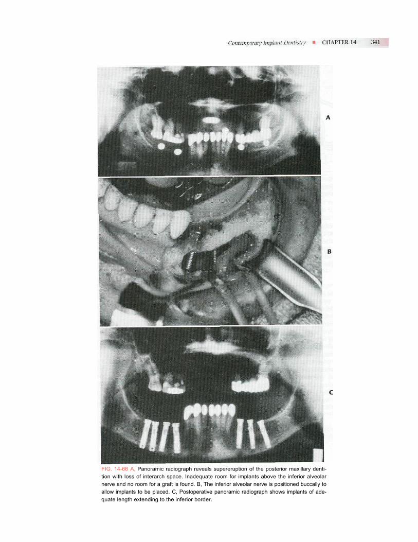
FIG. 14-66 A, Panoramic radiograph reveals supereruption of the posterior maxillary denti-tion with loss of interarch space. Inadequate room for implants above the inferior alveolar nerve and no room for a graft is found. B, The inferior alveolar nerve is positioned buccally to allow implants to be placed. C, Postoperative panoramic radiograph shows implants of ade-quate length extending to the inferior border.

Extraoral Implants Recognizing the success of implants for oral applications, maxillofacial prosthodontists and surgeons have expand-ed use of titanium fixtures to extraoral application. Extraoral implants are now used to anchor prosthetic ears, eyes, and noses for patients with defects resulting from congenital conditions, trauma, or pathology.
BIBLIOGRAPHY Adell R: Long-term treatment results. In Branemark PI, Zarb
G, Albrektson I, editors: Tissue-integrated prostheses, Chicago, 1985, Quintessence.
Adell R et al: A 15-year study of osseointegrated implants in the treatment of the edentulous jaw, Int J Oral Surg 10:387,1981.
Bain CA, May PK: The association between the failure of den-tal implants and cigarette smoking, Int j Oral Maxillofac Smplanti 8:609, 1993.
FIG. 14-67 The Zygomaticus implant, placed along with a mini-mum of two conventional implants in the anterior maxilla, will allow fabrication of an implant-supported maxillary denture without the need for sinus lift.
ated tissue, with results comparable to that found in non-irradiated patients. Little is known about the long-term results in these patients, and potential for increased fail-ure and serious sequelae (e.g., osteoradionecrosis) still exists. As a result, an experienced implant surgeon should manage implant placement in this group of patients.
Early Loading Since staged implant systems were first introduced, there have been efforts to define the minimum time required for osseointegration. Generally accepted integration times are based on experience and tradition with little experi-mental data. Research continues to attempt to define ideal minimum integration times. Factors that are likely impor-tant in determining what these minimum times should be include: bone quality, implant material, and surface and prosthesis configuration. Some studies have shown that early loading (i.e., 6 weeks) is successful when 5 implants in the anterior mandible are rigidly connected in a sup-porting framework. The most extreme variation on the theme of early loading is immediate loading. The Novum system relies on a jig to ensure exact implant position with a prosthesis supported by a machined titanium superstructure that is placed the same day as the implants.
Dahlin C et al: Generation of new bone around titanium implants using a membrane technique: an experimental study in rabbits, / Oral Maxillofac Implants 4:19, 1989.
Eriksson AR, Albrektsson T: Temperature threshold levels for heat-induced bone tissue injury: a vital microscopic study in the rabbit, ! Prosthet Dent 50:101, 1983.
Granstom G et al: A detailed analysis of titanium implants lost in irradiated tissue, Int / Oral Maxillofac Implants 9:653,1994.
Lazzara RJ: Immediate implant placement into extraction sites: surgical and restorative advantages, Int } Periodontia Restorative Dent 9:333, 1989.
McKinney RV, Steflik DE, Roth DL: The biologic response to single crystal sapphire endosteal implant: SEM observations, / Prosthet Dent 51:372, 1984.
Perrott, DH, Shama AB, Vargerik K: Endosseous implants for pediatric patients, Oral Maxillofac Clin N Am 6:79, 1994.
Peterson LJ et al: Comparison of mandibular bone response to implant overdentures versus implant-supported hybrid, I Dent Res 75:333, 1996.
Peterson LJ et al: Long-term antibiotic prophylaxis is not nec-essary for placement of dental implants, / Oral Maxillofac Surg 54(suppl 3):76, 1996.
Smith D, Zarb GA: Criteria for success for osseointegrated endosseous implants, / Prosthet Dent 62:567, 1989.
U.S. Department of Health and Human Services: Dental Implants, NIH Consensus Development Conference Statement, 7(3):108.
Veksler AE, Kayrouz GA, Newman MG: Chlorhexidine reduces salivary bacteria during scaling and root planing, / Dent Res 69:240, 1990.


![Denture Delivery [Removable Prosthodontics Seminar @AmCoFam]](https://img.dokumen.tips/doc/110x75/543eb8c3b1af9f700b8b47f1/denture-delivery-removable-prosthodontics-seminar-amcofam.jpg)