Embed Size (px)
Citation preview

Peter E. Bowden is the TechnicalServices Manager of John Crane EAA(Europe, Africa, and Asia). He is based inManchester, England, and is responsiblefor control of technical data across JohnCrane EAA. Mr. Bowden joined FlexiboxInternational in 1989 working in design,development, projects, and market develop-ment including two periods working inHouston. He was Project Manager for theZEST emission control sealing program
before taking up his current position in 2000. He has written andpresented a number of papers for technical conferences andjournals around the world relating to seal design, emissions, andreliability.
Mr. Bowden earned a B.Sc. degree (Mechanical Engineering,1979) from Stockport College of Technology. He is a member of theInstitution of Mechanical Engineers and a registered CharteredEngineer.
Chris J. Fone is the Director of TechnicalServices for John Crane EAA, based inSlough, United Kingdom. He joined JohnCrane in 1971 and has worked in varioustechnical roles including a period based inIran. He chairs the British StandardsInstitute committee for seals, the jointEuropean Sealing Association/Fluid Seal-ing Association Standards Task Force, andis a member of the task force creating the
Second Edition of API 682. He has written and presented a numberof technical papers on mechanical sealing to conferences aroundthe world.
Mr. Fone earned a B.Sc. Honors degree (Mechanical Engineer-ing, 1969) from Nottingham University. He is a member of theInstitution of Mechanical Engineers and a registered CharteredEngineer.
ABSTRACT
The impending revision of API 682/ISO 21049 will include drycontainment seals for the first time. These seals have beencommercially available for over 15 years. This paper reviews theperformance of these seals both in test and service in process plantsto assess their capabilities of meeting API 682 target objectives ofhigh reliability and emission control.
Options for secondary containment are reviewed though thepaper focuses on two principal types, dry contacting andnoncontacting containment seals. Data from the test laboratory arerelated to field experience and recommendations made for whenthe two types of design are best applied. Both emissionperformance and seal reliability experience are drawn fromrefineries in the United States, Europe, and the Asia Pacific regionsto validate operational expectations. Seal support systems for thetwo types of containment seals are described and reviewed.
INTRODUCTION
Application of dry (or gas lubricated) containment seals hasbeen increasing steadily for many years as process plant operatorshave sought better leakage control from their pump seals withoutthe cost of liquid barrier and buffer dual seals and systems.Application of mechanical containment seals has particularlyincreased on light hydrocarbon duties where single seals wouldfind it difficult to maintain compliance with local and nationalemission regulations. The forthcoming issue of API 682 SecondEdition/ISO 21049 (2001) formally recognizes this sealarrangement and will include it within the standard along withqualification test programs and recommendations for supportsystems.
This paper looks at the options available for containment sealingand reviews historical testing of mechanical containment seals(both contacting and noncontacting). Seal support systems to beincluded in API 682 Second Edition/ISO 21049 are described andguidelines given for their application. The paper also looks atperformance of these seals in process plants across the UnitedStates, Europe, and Asia, and compares this real life performancewith the targets set within the standard.
SECONDARY CONTAINMENT—GENERAL OBJECTIVES
The containment of primary seal leakage is a feature commonlyapplied to pump and compressor seal assemblies. The requirementfor leakage containment has various needs that influence thechoice of arrangement.
• Minimizing the fluid loss to the atmosphere upon failure of theprimary seal and reducing the resulting hazard potential
• Assist channeling primary seal leakage to a suitable collectionpoint to maintain cleanliness and permit monitoring of primaryseal operation
• Reducing the hazard potential caused by primary seal leakage
• Reducing or eliminating the atmospheric pollution potentialarising from primary seal leakage
67
CONTAINMENT SEALS FOR API 682 SECOND EDITION
byPeter E. Bowden
Technical Services Manager
John Crane EAA
Manchester, England
andChris J. Fone
Director of Technical Services
John Crane EAA
Slough, England
• Sealing quench fluids
Typical containment techniques that are applicable tocombinations of the above features are described below undersection “SECONDARY CONTAINMENT—TECHNIQUES ANDDESIGNS,” together with a discussion of the strengths andweaknesses of the options.
This document however primarily addresses the hazard andpollution issues of secondary containment and not the containmentof quench fluids for other reliability benefits. It is in thiscontainment role that seal suppliers have developed products thatare intended to provide the following functions.
• A period of operation equivalent to the design life expected ofthe primary seal and during which the primary seal leakage toatmosphere will be contained within acceptable levels
• A capability of alarming the operator when the primary sealleakage has exceeded normal levels and a capability of providingeffective containment for a short period of time thereafter. Thisdelay period is to enable the equipment to be shutdown withoutaffecting the normal running of the plant process and maintenancefunctions.
This latter design specification is sometimes misunderstoodby some individuals. In some quarters there is a presumptionthat the secondary containment system can be arranged toprovide an equivalent environment to that enjoyed by theprimary seal for an indefinite period. This is not normallypractical and ignores the main function of secondarycontainment: to provide a second line of defense in minimizinghazard and atmospheric pollution.
This was appreciated by the task force developing the draft ofAPI 682 Second Edition/ISO 21049 and resulted in the followingobjective stated by the standard.
Containment seals should run for at least 25000 h (wet ordry seals) at any containment seal chamber equal to orless than the seal leakage pressure switch (not to exceeda gauge pressure of 0.7 bar (10 psi)) and for at least 8 hat the full seal chamber conditions (API 682 SecondEdition/ISO 21049, 2001).
SECONDARY CONTAINMENT—TECHNIQUES AND DESIGNS
Fixed Bushings
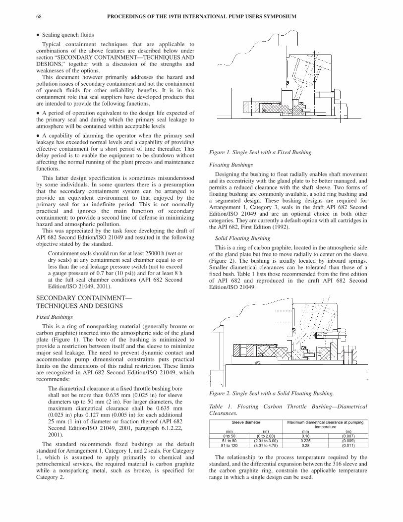
This is a ring of nonsparking material (generally bronze orcarbon graphite) inserted into the atmospheric side of the glandplate (Figure 1). The bore of the bushing is minimized toprovide a restriction between itself and the sleeve to minimizemajor seal leakage. The need to prevent dynamic contact andaccommodate pump dimensional constraints puts practicallimits on the dimensions of this radial restriction. These limitsare recognized in API 682 Second Edition/ISO 21049, whichrecommends:
The diametrical clearance at a fixed throttle bushing boreshall not be more than 0.635 mm (0.025 in) for sleevediameters up to 50 mm (2 in). For larger diameters, themaximum diametrical clearance shall be 0.635 mm(0.025 in) plus 0.127 mm (0.005 in) for each additional25 mm (1 in) of diameter or fraction thereof (API 682Second Edition/ISO 21049, 2001, paragraph 6.1.2.22,2001).
The standard recommends fixed bushings as the defaultstandard for Arrangement 1, Category 1, and 2 seals. For Category1, which is assumed to apply primarily to chemical andpetrochemical services, the required material is carbon graphitewhile a nonsparking metal, such as bronze, is specified forCategory 2.
Figure 1. Single Seal with a Fixed Bushing.
Floating Bushings
Designing the bushing to float radially enables shaft movementand its eccentricity with the gland plate to be better managed, andpermits a reduced clearance with the shaft sleeve. Two forms offloating bushing are commonly available, a solid ring bushing anda segmented design. These bushing designs are required forArrangement 1, Category 3, seals in the draft API 682 SecondEdition/ISO 21049 and are an optional choice in both othercategories. They are currently a default option with all cartridges inthe API 682, First Edition (1992).
Solid Floating Bushing
This is a ring of carbon graphite, located in the atmospheric sideof the gland plate but free to move radially to center on the sleeve(Figure 2). The bushing is axially located by inboard springs.Smaller diametrical clearances can be tolerated than those of afixed bush. Table 1 lists those recommended from the first editionof API 682 and reproduced in the draft API 682 SecondEdition/ISO 21049.
Figure 2. Single Seal with a Solid Floating Bushing.
Table 1. Floating Carbon Throttle Bushing—DiametricalClearances.
The relationship to the process temperature required by thestandard, and the differential expansion between the 316 sleeve andthe carbon graphite ring, constrain the applicable temperaturerange in which a single design can be used.
PROCEEDINGS OF THE 19TH INTERNATIONAL PUMP USERS SYMPOSIUM68
Sleeve diameter Maximum diametrical clearance at pumpingtemperature
mm (in) mm (in)0 to 50 (0 to 2.00) 0.18 (0.007)51 to 80 (2.01 to 3.00) 0.225 (0.009)
81 to 120 (3.01 to 4.75) 0.28 (0.011)

CONTAINMENT SEALS FOR API 682 SECOND EDITION 69
Segmented Floating Bushing
Segmenting the ring and utilizing a garter spring for retentioncan further reduce radial clearance between the shaft sleeve and thefloating bushing (Figure 3). Axial springs again act to position thebushing. The circumferential flexibility can be used toaccommodate dimensional tolerances and differential expansion.This technology, developed originally for steam turbine seals, hasa designed contact between sleeve and bushing, but after a periodof wear typically operates with a diametrical gap of approximately0.04 mm (0.0015 in). This gap reduces significantly with theapplication of a pressure differential, thus further reducing theleakage through the bore.
Figure 3. Segmented Floating Bushing.
Lip Seals
This technology is available in elastomeric and polymerdesigns but is rarely used for secondary containment. The lowcost and short axial length make it an attractive solution, but thetechnology is currently unable to provide the effectivecontainment and mean time between repair (MTBR) expectationsof plant operators with the low viscosity fluids and widetemperature ranges applied in the field. For these reasons thistechnology has not yet been included in the choices available inthe draft API 682 Second Edition/ISO 21049 and will not becovered in this document.
Lip seals are used in specialist secondary containmentarrangements, primarily to retain quench fluids, particularly thosethat have sufficient lubricating properties or where there is sometolerance to slight leakage.
Abeyant Seals
This terminology describes a principle of operation requiring thecontainment seal to be effective in the event of an excessiveleakage from the primary seal, but only offering limited sealingfunction in normal operation. Most of the designs available rely onthe primary seal leakage flow generating a pressure differential in
the arrangement that moves or activates a normally dormantsecondary containment seal.
There are still many abeyant secondary seals operating in thefield, and there are frequent examples where the technology hasprevented a major hazard occurring. The principle however nowhas limited application because other available technologies canoffer improved and reliable containment at all the primary sealleakage rates. For this reason the draft API 682 SecondEdition/ISO 21049, and its current predecessor, does not includethe option for this principle and it will not be included in furtherparts of this document.
Dry (Gas Lubricated) Mechanical Seals
Technologies have been developed to enable the faces ofmechanical seals to operate reliably in a gaseous environmentwithout needing liquid lubrication. This opens the opportunity forsimplified but reliable secondary containment with radial facedmechanical seals. Although they are ordinarily lubricated by theprocess leakage entering the containment chamber, they can alsobe used with an injected buffer gas where this is desired.
This technology and its application to secondary containmenthave been widely used for more than a decade and are referenced inAPI 610, Eighth Edition (1995). Although not included in the firstedition of API 682 it is now a formal part of the draft API 682Second Edition/ISO 21049 as a selection option in the Arrange-ment 2 configuration and in all three categories. In conformancewith other alternative configurations recommended by the standard,the design and applicability of this technology are addressed. Aseries of qualification tests that imitate its use in the field is part ofthe specification (refer to section “API 682, Second Edition,Qualification Tests”). The standard also requires a fixednonsparking bushing to be installed inboard of the containment sealfaces and downstream of the containment chamber vent connectionto help isolate the faces from the process leakage (Figure 4).
Figure 4. Dual Seal with External Dry Contact Containment Seal.
Two alternative gas lubricated technologies are described below.
Dry Contacting Seals
The design and materials technology now available enables theuse of radial faced mechanical seals to operate in a gas with anacceptable MTBR capability at pump 2 pole speeds (Figure 4). Thedry rubbing contact restricts the technology to a low pressurerange, but the material properties also enable much higher liquidlubricated performance with the same seal face pairing. Thecapability thus exists for effective containment of normal primaryseal leakage in whatever physical state it is at ambient conditions,plus containment in the event of a major failure of the primary sealwithout the need for a separate lubricating buffer fluid (refer tosection “Dry (Gas Lubricated) Mechanical Seals” below).
Dry Noncontacting Seals
Noncontacting gas seal technology can also be applied to themechanical seal using macro adjustment of the rubbing face profile

and surface (Fone, 1995). When in dynamic operation the seal faceoperates with a full separation of the running parts but, in all otherrespects, functions in the same way as the dry contacting seal(Figure 5). Statically the faces physically contact and, having a fullcircumferential region where this occurs, minimizes leakage.
Figure 5. Dual Seal with External Dry Noncontact ContainmentSeal.
The draft API 682 Second Edition/ISO 21049 considers theacceptability of both technologies but recommends a default to thenoncontacting design, arguing the technology is more tolerant ofpressure excursions in the normal arrangement when thecontainment chamber is connected to the plant flare system. Theseissues are discussed below in section “Dry (Gas Lubricated)Mechanical Seals.”
Dual Contacting Wet Seals with an Unpressurized Buffer
This configuration uses a mechanical seal between the primaryseal and atmosphere for secondary containment, but lubricates itsfaces with a liquid buffer fluid (Figure 6). This fills thecontainment chamber and is supplied by an externally connectedreservoir. Primary seal leakage, normally in gaseous form, entersthe buffer liquid system and is removed through the reservoirconnection to the flare.
Figure 6. Dual Contacting Wet Seal with an Unpressurized Buffer.
This robust arrangement has been used for secondarycontainment for decades and the seal arrangement has been part ofAPI 610 over this period. It is classed as Arrangement 2 in thecurrent API 682, First Edition, and is reproduced as one of theArrangement 2 options in all three categories of the draft API 682Second Edition/ISO 21049. The Standard requires a circuit loopwith a positively circulated buffer liquid and a heat exchanger toremove heat to ensure reliability in the outer seal.
SECONDARY CONTAINMENT—SELECTION
The selection criteria for secondary containment seals must be ajudgement on the potential hazard or atmospheric pollutioncapability arising from normal primary seal leakage and that
arising from a failure (refer to discussion in section“SECONDARY CONTAINMENT—GENERAL OBJECTIVES”above). Corporate and plant standards as well as local government,national, and transnational regulations however also influencethese judgements. Definitive rules are thus impractical, but designfunction can offer guidance in selection. These issues are discussedbelow.
Bushings
The diametrical clearances practical with fixed bushings limittheir applicability for secondary containment. At normal leakagelevels their shape at the containment chamber exit does encouragethe channeling of liquid leakage through the gland plate drainconnection. They however offer negligible containment or flowchanneling in the event of the primary seal leakage being gaseous,but do assist with the throttling of flow to the atmosphere atexcessive liquid leakage levels. The main contribution of fixedbushings in hazard reduction primarily occurs in the event of ashaft bearing failure; being the closest radial contact point, theyprovide a frontline nonsparking contact region for the shaft sleeveand radial protection for vulnerable seal components.
The simplicity and small dimensional boundaries still makethese limited benefits attractive where the need for hazardmanagement is not a major factor in secondary containment, and iswhy they are a common feature on single seal cartridges.
With a cube power relationship between flow and bushingclearance, there is significantly improved containment capabilitywith the floating bushing. This is the source of the preference inAPI 682, First Edition, and why the draft API 682 SecondEdition/ISO 21049 defaults to this design on Category 3 seals.Other benefits feature with the floating bushing such as easierassembly on between-bearing pump designs. Radial movementmust be generous to minimize the potential of clogging and permiteffective draining, whereas this may compromise the protectivefeatures of the bushing. One solution is the construction of theretaining plate in bronze with a fixed bushing clearance on thesleeve (Figure 3). The plate section and clamping of the retainingplate must be designed for the maximum potential chamberpressure.
In API 682, First Edition, while not normally recommended ondual seal arrangements, the floating bushing was left as an optionfor those process temperature extremes when the barrier or bufferfluid may itself be a hazard or there is a potential that icing mayimpede seal flexibility. The effectiveness of their function is notuniversally accepted, and this option has been removed from thesecond edition unless a separate agreement with the vendor isarranged. Practical axial length constraints, required by the pumpindustry to improve reliability, compromise the primary function ofdual seals if a bushing is specified.
A result of designing for a maximum range of temperature forthe solid ring floating bushing is that maximum clearance willoccur at the lower temperatures that are more typical in serviceswhere the process leakage is gaseous at ambient conditions. Itscontainment role is thus still limited for these high vapor pressureprocesses, and a segmented ring design offers far superiorcapability in these circumstances (Figures 7 and 8).
In conclusion bushings provide various levels of containment,primarily minimizing the fluid loss to the atmosphere upon failureof the primary seal and reducing the resulting hazard potential.They assist in channeling primary seal liquid leakage to a suitablecollection point to maintain cleanliness, and enable monitoring ofprimary seal operation.
Dry (Gas Lubricated) Mechanical Seals
The development of gas lubrication on radial faced mechan-ical seals has filled a gap in the secondary containment capabilityof bushings. The smaller leakage levels that can be achieved offer the plant operator a far improved containment of gaseous
PROCEEDINGS OF THE 19TH INTERNATIONAL PUMP USERS SYMPOSIUM70
CONTAINMENT SEALS FOR API 682 SECOND EDITION 71
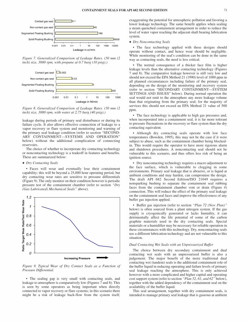
Figure 7. Generalized Comparison of Leakage Rates. (50 mm (2inch) size, 3000 rpm, with propane at 0.7 barg (10 psig).)
Figure 8. Generalized Comparison of Leakage Rates. (50 mm (2inch) size, 3000 rpm, with water at 2.75 barg (40 psig).)
leakage during periods of primary seal disturbance or during itsfailure cycle. It also allows effective connection of leakage to avapor recovery or flare system and monitoring and warning ofthe primary seal leakage condition (refer to section “SECOND-ARY CONTAINMENT—SYSTEMS AND OPERATION”below) without the additional complication of connectingreservoirs.
The choice of whether to incorporate dry contacting technologyor noncontacting technology is a tradeoff in features and benefits.These are summarized below:
• Dry Contacting Seals
• Faces will wear and eventually lose their containmentcapability; this will be beyond a 25,000 hour operating period, butdry contacting wear rates are sensitive to pressure differentials(Figure 9). The only monitor on their condition however is periodicpressure test of the containment chamber (refer to section “Dry(Gas Lubricated) Mechanical Seals” above).
Figure 9. Typical Wear of Dry Contact Seals as a Function ofPressure Differential.
• The sealing gap is very small with contacting seals, andleakage to atmosphere is comparatively low (Figures 7 and 8). Thisis seen by some operators as being important when directlyconnected to vapor recovery or flare systems; in this scenario theremight be a risk of leakage back-flow from the system itself,
exaggerating the potential for atmospheric pollution and favoring alower leakage technology. The same benefit applies when sealinga steam quenched containment arrangement in order to reduce thelevel of water vapor reaching the adjacent shaft bearing lubricationsystem.
• Dry Noncontacting Seals
• The face technology applied with these designs shouldoperate without contact, and hence wear should be negligible.While monitoring of the seal’s condition can be done in the sameway as contacting seals, the need is less critical.
• The normal consequence of a thicker face film is higherleakage levels than the alternative contacting technology (Figures7 and 8). The comparative leakage however is still very low andshould not exceed the EPA Method 21 (1990) level of 1000 ppm inall planned circumstances including failure of the primary seal,depending on the design of the monitoring and recovery system(refer to section “SECONDARY CONTAINMENT—SYSTEMSETTINGS AND ISSUES” below). During normal operation theseal would not emit to the atmosphere any more leakage volumethan that originating from the primary seal; for the majority ofservices this should not exceed an EPA Method 21 value of 500ppm.
• The face technology is applicable to high gas pressures and,when incorporated into a containment seal, it is far more tolerantto pressure fluctuations in the recovery or flare system than the drycontacting equivalent.
• Although dry contacting seals operate with low facetemperatures (Bowden, 1995), this may not be the case if it weresubject to abuse, such as the containment chamber being blocked-in. This would require the operator to have more rigorous alarmand shutdown procedures. A noncontacting seal should not bevulnerable to this scenario, and thus offers less risk of being anignition source.
• Dry noncontacting technology requires a macro adjustment tothe face surface, which is vulnerable to clogging in someenvironments. Primary seal leakage that is abrasive, or is liquid atambient conditions and may harden, can compromise the design.The draft API 682 Second Edition/ISO 21049 requires anonsparking bushing to separate the containment seal rubbingfaces from the containment chamber vent or drain (Figure 4)connection. This will reduce the effect of the primary seal leakageon the containment seal faces and improve the effectiveness of anybuffer gas injection applied.
• Buffer gas injection (refer to section “Plan 72 (New Plan)”below) is often sourced from a plant nitrogen system. If the gassupply is cryogenically generated or lacks humidity, it candetrimentally affect the life potential of some of the carbongraphite materials used in the dry contacting seals. Specialmaterials or a humidifier may be necessary for reliable operation inthese circumstances with this technology. Dry, noncontacting sealsuse a different lubrication technology and are not vulnerable to thissituation.
Dual Contacting Wet Seals with an Unpressurized Buffer
The choice between dry secondary containment and dualcontacting wet seals with an unpressurized buffer is also ajudgement. The major benefit of the more traditional dualcontacting wet (tandem) seals is the additional containment role ofthe buffer liquid in reducing operating and failure levels of primaryseal leakage reaching the atmosphere. This is only achievedhowever with a more complicated and higher capital and operatingcost support system (refer to section “Plan 52, 61, and 62” below),together with the added dependency of the containment seal on theavailability of the buffer liquid.
This seal arrangement, together with dry containment seals, isintended to manage primary seal leakage that is gaseous at ambient
200
3
0.03
0.002
0.001 0.01 0.1 1 10 100 1000
Leakage in Nl/min
200
3
0.03
0.002
0.001 0.01 0.1 1 10 100 1000
Solid Floating Bushing
Segmented Floating Bushing
Non-contact gas seal
Contact gas seal
Leakage in Nl/min
Rat
io T
arg
et W
ear
Rat
e/Te
st W
ear
Rat
e

conditions. If there is a high proportion of liquid primary sealleakage, this will have the effect of contaminating the buffer liquidand increasing the hazard and seal system reliability. This problemcan be overcome by the application of increased reservoirmonitoring and the use of a high-level alarm switch; regularreplacement of the buffer fluid is also required (refer to section“Plan 52, 61, and 62” below). The containment benefits howeversometimes outweigh the added operating cost. As the alternative isa more complicated pressurized dual seal, the dual unpressurizedcontacting wet seals are still sometimes used in these services.Processes with higher specific gravity (sg) than the buffer liquid orwater contaminated services aggravate the problem; they have atendency to displace the buffer and compromise the wetcontainment seal. This arrangement is not recommended in thesecircumstances.
The presumption by some engineers that the buffer liquidenhances cooling of the primary seal is an inaccurate assumptionwhen the process leakage is gaseous; the gas typically centrifugesinto the region where heat transfer may otherwise have beenachieved. In addition, on services where the buffer balancetemperature is higher than the process flush, consideration needs tobe made for an additional heat flux into the primary seal fluid filmwhere it may affect the film’s stability and potential vapor pressuremargin.
SECONDARY CONTAINMENT—SYSTEMS AND OPERATION
The containment seal and its associated chamber need theaddition of a support system to enable the primary seal leakagelevel to be monitored and alarm systems to be activated at apredetermined level. Leakage levels from the containment seal toatmosphere normally have an association with the condition in thecontainment chamber. The majority of support systems measurethe condition in the containment chamber and at predeterminedlevels have operational strategies applicable to the equipment. Thesections below (“System Piping Diagrams”) describe the functionof commonly used support systems, their relevance to the draft API682 Second Edition/ISO 21049, and the factors influencing thechoice. The subsequent section (“SECONDARY CONTAINMENT—SYSTEM SETTINGS AND ISSUES”) discusses the design andinclusion of some of the components within the systemsthemselves.
System Piping Diagrams
International pump standards, and more recently API 682, FirstEdition, have recommended system piping diagrams for secondarycontainment. The “plan” references in API 610 are the mostconsistently used descriptions, but in the draft of the ninth editionof this standard, now also being considered as a draft of ISO13709, the plans are being excluded. In future they will only beavailable in the draft API 682 Second Edition/ISO 21049 and toaccommodate additional secondary containment configurations.Four new plans have been added.
The key to piping connection descriptions in the plans shown inFigures 10 to 17 is:
Key:CSD = Containment seal drainCSV = Containment seal ventD = DrainGBI = Gas buffer inletLBI = Liquid buffer inletLBO = Liquid buffer outletQ = Quench
Plan 52, 61, and 62
Secondary containment is currently accommodated in API 610,Eighth Edition, and API 682, First Edition, by the designation Plan
52 (Figure 10), Plan 61 (Figure 11), and Plan 62 (Figure 12). Whilethese cater for dual contacting wet seals with an unpressurizedbuffer liquid (Plan 52) and bushing solutions, they are notapplicable to dry mechanical containment seals. These existingplans continue to be retained in the draft API 682 SecondEdition/ISO 21049.
Figure 10. Plan 52 Support System.
Figure 11. Plan 61 Support System.
Plan 71 (New Plan)
Plan 71 (Figure 13), while not including additional equipment,is the default piping connection arrangement for the containmentchamber intended for dry mechanical containment seals. It ismainly intended to be used in conjunction with other plans (refer
PROCEEDINGS OF THE 19TH INTERNATIONAL PUMP USERS SYMPOSIUM72
CONTAINMENT SEALS FOR API 682 SECOND EDITION 73
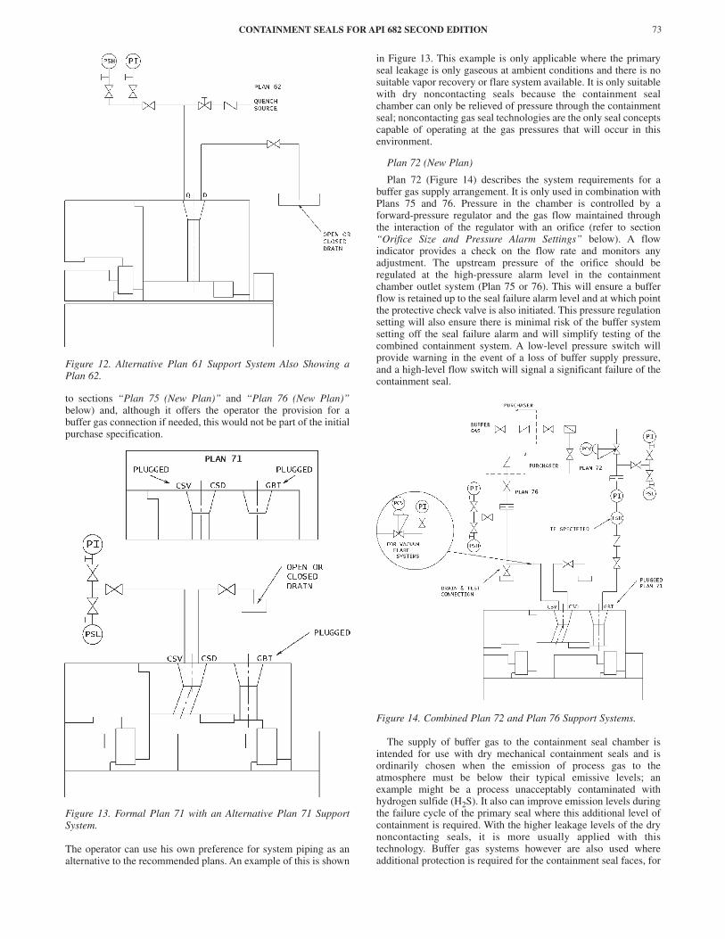
Figure 12. Alternative Plan 61 Support System Also Showing aPlan 62.
to sections “Plan 75 (New Plan)” and “Plan 76 (New Plan)”below) and, although it offers the operator the provision for abuffer gas connection if needed, this would not be part of the initialpurchase specification.
Figure 13. Formal Plan 71 with an Alternative Plan 71 SupportSystem.
The operator can use his own preference for system piping as analternative to the recommended plans. An example of this is shown
in Figure 13. This example is only applicable where the primaryseal leakage is only gaseous at ambient conditions and there is nosuitable vapor recovery or flare system available. It is only suitablewith dry noncontacting seals because the containment sealchamber can only be relieved of pressure through the containmentseal; noncontacting gas seal technologies are the only seal conceptscapable of operating at the gas pressures that will occur in thisenvironment.
Plan 72 (New Plan)
Plan 72 (Figure 14) describes the system requirements for abuffer gas supply arrangement. It is only used in combination withPlans 75 and 76. Pressure in the chamber is controlled by aforward-pressure regulator and the gas flow maintained throughthe interaction of the regulator with an orifice (refer to section“Orifice Size and Pressure Alarm Settings” below). A flowindicator provides a check on the flow rate and monitors anyadjustment. The upstream pressure of the orifice should beregulated at the high-pressure alarm level in the containmentchamber outlet system (Plan 75 or 76). This will ensure a bufferflow is retained up to the seal failure alarm level and at which pointthe protective check valve is also initiated. This pressure regulationsetting will also ensure there is minimal risk of the buffer systemsetting off the seal failure alarm and will simplify testing of thecombined containment system. A low-level pressure switch willprovide warning in the event of a loss of buffer supply pressure,and a high-level flow switch will signal a significant failure of thecontainment seal.
Figure 14. Combined Plan 72 and Plan 76 Support Systems.
The supply of buffer gas to the containment seal chamber isintended for use with dry mechanical containment seals and isordinarily chosen when the emission of process gas to theatmosphere must be below their typical emissive levels; anexample might be a process unacceptably contaminated withhydrogen sulfide (H2S). It also can improve emission levels duringthe failure cycle of the primary seal where this additional level ofcontainment is required. With the higher leakage levels of the drynoncontacting seals, it is more usually applied with thistechnology. Buffer gas systems however are also used whereadditional protection is required for the containment seal faces, for

example, waxing or heavy hydrogen chloride (HC) residue. Someoperators even choose this plan as a means of keeping orificesclean (refer to section “Orifice Size and Pressure Alarm Settings”below).
In cryogenic services it can be used to prevent icing, but in thesecircumstances the system is better applied through the quenchconnection of a Plan 62 with a fixed bushing (Figure 12). In thissituation, to avoid an error in the connection position, it cannot bereferenced Plan 72 and would come under the umbrella descriptionof a Plan 62. Specialized containment seals, not included in thedraft API 682 Second Edition/ISO 21049, can be used with thisPlan 62 quench gas system to provide a more secure containmentin potentially toxic services. The quench gas is pumped into thecontainment chamber using inner diameter located spiral groovetechnology, and is then combined with a Plan 76 exit system(Figure 15).
Figure 15. Combined Alternative Plan 62 and Plan 76 SupportSystem.
Plan 75 (New Plan)
Plan 75 systems (Figure 16) are connected to the outlet of thecontainment chamber incorporating dry containment seals butin services where the primary seal leakage has a highproportion of process fluid that is liquid at ambient conditions.It consists of a reservoir that is intended to collect the liquidproportion of the contained primary seal leakage with a high-level switch to warn the operator that a fixed quantity ofleakage has occurred and there is the risk of contaminating thevapor recovery or flare system. The draft API 682 SecondEdition/ISO 21049 provides design recommendations for thisreservoir. A drain connection in the reservoir allows the liquidto be safely removed. An upper tapping is connected to a vaporrecovery or flare system through an orifice and an upstreamhigh-level pressure switch (refer to Plan 52 in section “Plan52, 61, and 62” above and section “Plan 76 (New Plan)”below). This is preset to alarm at an excessive flow conditionrelated to a primary seal failure (refer to section “Orifice Sizeand Pressure Alarm Settings” below).
Figure 16. Plan 75 Support System.
A pressure indicator is recommended to permit monitoring ofthe primary seal leakage rate prior to the alarm condition, and alevel gauge in the reservoir allows the operator to monitor thequantity of liquid collected prior to the alarmed condition. A blockvalve in the connection to the vapor recovery or flare system canbe shut and used to monitor the system function and condition ofthe containment seal by measuring the pressure buildup rate. Thedraft API 682 Second Edition/ISO 21049 however recommends theinclusion of a test connection to allow the static checking of thesystem function and the condition of the containment seal itselfusing a separate gas source (refer to section “Dry (Gas Lubricated)Mechanical Seals” above).
The primary use of this plan has been described above butoperators may choose its features, instead of Plan 76, even onprocess services that have a major proportion of vapor at ambientconditions, in order to protect their recovery systems from liquidcontamination. Alternatively, where the process condition is nearlycompletely liquid at ambient and a closed drain is available, Plan75 is considered overcomplicated and the system shown in Figure17 is applied. The principle of operation is the same but sizing ofthe orifice has a different set of parameters (refer to section“Orifice Size and Pressure Alarm Settings” below).
Dry containment seals are available for hot hydrocarbon serviceswhere steam is used to prevent coking of the primary seal as wellas functioning as a buffer gas to minimize the flammable risk. Themonitor and containment system described in Figure 17 can also beused in these circumstances but with a steam supply connected tothe containment chamber inlet connection.
Plan 76 (New Plan)
Plan 76 (Figure 14) is the alternative system to the Plan 75 forchanneling and monitoring primary seal leakage from thecontainment chamber incorporating dry containment seals. Thesystem is intended for process services that are primarily gaseousat ambient conditions. Its function is the same as the vapor tappingon the collection reservoir of the Plan 75; the containment chambervent connection is connected to a vapor recovery or flare systemthrough an orifice and an upstream high-level pressure switch
PROCEEDINGS OF THE 19TH INTERNATIONAL PUMP USERS SYMPOSIUM74

CONTAINMENT SEALS FOR API 682 SECOND EDITION 75
Figure 17. Alternative Liquid Process Containment System(Including a Steam Buffer).
(refer to section “Orifice Size and Pressure Alarm Settings”below). This is preset to alarm at an excessive flow conditionrelated to a primary seal failure. The Plan 76 can be used with aPlan 71 or Plan 72, but would not normally be combined with aPlan 75.
A block valve in the Plan 76 system is intended to facilitatemaintenance, but in the same manner as the Plan 75 it can be shutand used to monitor the system function and condition of thecontainment seal by measuring the pressure buildup rate. A drainvalve is recommended in the circuit to remove any buildup ofcondensate in the vapor circuit, but it can also be used as part of analternative testing method (refer to section “SECONDARYCONTAINMENT—DRY MECHANICAL SEAL INSTALLEDTESTING” below). A separate gas source can be applied to theconnection that, when combined with the block valve, can also beused to check the system function and the condition of thecontainment seal itself (refer to section “SECONDARYCONTAINMENT—DRY MECHANICAL SEAL INSTALLEDTESTING” below).
There may be some unusual circumstances when the vaporrecovery or flare system is ordinarily at a slight vacuum and there isthe potential of air ingress through the containment system and seal.In these circumstances a back-pressure regulator can be insertedupstream of the orifice and alarm switch to maintain a slightlypositive pressure in the seal containment chamber (Figure 14).
SECONDARY CONTAINMENT—SYSTEM SETTINGS AND ISSUES
Orifice Size and Pressure Alarm Settings
The orifice and pressure alarm are interconnected componentsproviding the fundamental condition monitoring elements in Plans52, 72, 75, and 76. The slightly different functions of these plans andextensive field operational experience have resulted in significantvariability in the specification of these monitoring components. In
the first edition of API 682, and repeated in the draft API 682Second Edition/ISO 21049, is a specification for a minimum orificediameter of 3 mm (1/8 in). There is also an intent throughout thislatter draft standard (refer to section “SECONDARYCONTAINMENT—GENERAL OBJECTIVES” above) that themaximum upstream pressure alarm signal with dry containmentsystems should be a gauge pressure of 0.7 barg (10 psig).
The graph in Figure 18 demonstrates that with a flow of propanethrough a 3 mm (0.120 in) orifice and at the maximum differentialcondition implied by the standard, the flow rate, which is directlyrelated to the primary seal leakage, would be 84.5 l/min (2.98scfm) or 157 gm/min. While this is still effectively contained bythe containment seal, it would be unusual for an operator to toleratethis loss of product. The reality is however that system back-pressures (see below) would reduce this maximum differential. Inaddition many field-installed orifices have the effective orifice sizereduced with process impurities, wax dropout from somehydrocarbon mixtures. The fluid passing through them can often bea multiphase fluid or even sometimes completely liquid. It is thusnot surprising in a standard driven by operator experience, therelationship and specification of orifice size and alarm conditionare conservatively rated compared to a theoretical prediction.
Figure 18. Theoretical Flow Rates of Propane at 20°C (68°F) withDifferent Diameter Flow Control Orifices.
Some operators may not like to have this level of designcompromise, and it is not unusual to have field installations with 2mm (0.080 in) diameter orifices used in Plans 52, 75, and 76systems with upstream high-pressure alarm switches ortransmitters set at a gauge pressure of 0.5 bar (7 psi). Ignoring theinfluence of background system pressure, this reduces thetheoretical maximum primary seal leakage to a more reasonablelevel of 30.9 l/min (1.09 scfm) or 58 gm/min (Figure 18).
The pressure alarm setting is influenced by the vapor recovery orflare system condition, which is normally a slightly positivepressure, typically about a gauge pressure of 0.2 bar (3 psig).Normal operating pressures of flare systems vary, however, as doestheir condition at peaks of usage. It is thus recommended the high-pressure alarm system is based on a differential pressure of 0.5 bar(7 psi) above the mean operating condition in the vapor recovery orflare system. If peak values exceed this setting regularly and thealarm level has to be set to exceed the gauge pressure of 0.7 bar (10psi), the scope of the draft API 682 Second Edition/ISO 21049 isexceeded (refer to section “SECONDARY CONTAINMENT—GENERAL OBJECTIVES” above). This is then likely to restrictthe choice of secondary containment seal to a noncontacting gaslubricated technology or a liquid buffer lubricated system (Plan 52).
Where orifices are used with upstream high pressure alarmswitches to monitor and warn of excessive flow with liquids, a 3mm (0.120 in) diameter minimum size is a practical solution and isadvisable in the system recommended on Figure 17. In some

circumstances heating might be required in the location of theorifice to prevent process solidification. Without a high level alarmon Plans 52 and 75, there is a risk the reservoir will overfill and theorifice will experience liquid or a mixed phase instead of thedesign media, gas. This is a major reason why the draft API 682Second Edition/ISO 21049 recommends the level warning feature,but without the level alarm the standard’s 3 mm (0.120 in)minimum orifice diameter has a stronger practical case for itsinclusion.
In all the above cases the high-pressure alarm setting should notexceed the primary seal chamber condition, otherwise it may neverprovide the planned warning. Care must be taken on serviceswhere very low primary seal pressures are encountered, such as thebottom of distillation towers, and alarm settings must be adjustedto consider this issue.
The orifice used with the Plan 72 buffer gas system has adifferent function; when used in combination with the forward-pressure regulator, it will control the buffer gas flow rate. The levelof flow rate used will be a compromise in emission reductioneffectiveness and monitoring sensitivity, but a value of between 10and 20 l/min is a practical guide. To control gas flow rate in thisrange will require an orifice size significantly smaller than theminimum orifice diameter of 3 mm (0.120 in) specified in the draftAPI 682 Second Edition/ISO 21049. With a typical pressurebreakdown of 0.5 bar (7 psi) between high-pressure alarm pointand normal vapor recovery or flare pressure (refer above), bufferflow rates may only be achieved with a capillary orifice design.
The draft API 682 Second Edition/ISO 21049 is a technical andprocess purchasing recommendation with a defined scope and apractical level of complexity. It is clear from the above discussionsthat it cannot cater for all eventualities and there must be room forflexibility. It thus presumes it customary for users of the standardto clarify where exceptions to this are necessary or preferred.
Check Valves
Check valves are recommended as a means of preventing reverseflow from vapor recovery or flare systems to the containmentchamber on Plan 75 and 76 systems. They are also employed toprevent contamination of quench and buffer gas supply sources inPlan 62 and 72 systems.
Process contamination, slowly acting and low pressure-reversals, plus other factors have been the sources of unreliabilitywith check valves used in some secondary containment systems. Inthese circumstances plant operators may prefer to remove thepresumed reliance on their function by excluding them. This forcesrecognition of the potential for reverse flow and a more practicaljudgment of the system’s reliability, hazard, and emission-to-atmosphere potential. The vent connection in the historicallyapplied Plan 52 system has never recommended a check valve, andin a survey of vent configurations in existing dry containment sealarrangements (Plan 76), the majority had been assembled withouta check valve. Where they have been used, the operator hassometimes chosen to install the valve some distance from therotating equipment and at a level above the main flare systemmanifold in an attempt to try to improve its reliability and reducevulnerability to contamination from upstream sources.
The same sources of unreliability do not occur in quench/buffersupply systems (Plans 62 and 72) and filling of Plan 52 reservoirs.In these circumstances check valves are commonly used to protectsupply sources.
The draft API 682 Second Edition/ISO 21049 makes recommen-dations on all these issues, but there is provision for users orsuppliers to take exceptions where their local experience advises this.
SECONDARY CONTAINMENT—DRY MECHANICAL SEAL INSTALLED TESTING
The effective condition of the dry mechanical containment sealis critical to the secondary containment system, and the ability to
check and test it is required. The systems described in the abovesections “Plans 75” and “Plan 76” have this feature built in.
Static Testing
A static gas pressure test is the simplest process, and the draftAPI 682 Second Edition/ISO 21049 recommends a procedure aspart of the checks during the seal qualification test process. This isa repeat of the normal API 610/682 air test applicable to primaryjob seal testing.
The containment seal chamber must first be isolated from thevent and drain systems but retaining the pressure gauge and alarmswitch within the test circuit. If there is any risk of liquid beingretained in the connecting pipework, this must be drained safelyand the test volume depressurized from the normal systemcondition. Check the pressure rise resulting from static primaryseal leakage over a five minute period; the sensitivity is very highon high vapor pressure services. If the rise is less than 0.2 bar (3psi) the API 610/682 air test can then be applied using a test gasconnected through the test connection and pressurizing thecontainment chamber to 1.8 barg (26 psig). The test volume is thenisolated from the test gas and the pressure drop measured over afive minute period. This will give a guide to the seal’s condition;this should not exceed 0.14 bar (2 psi) for a containment seal ingood condition. The high pressure alarm function can also bechecked during the same test. If the pressure drop has a muchhigher rate, it is advisable to check the condition of other potentialleak paths, such as flange gaskets and piping joints, beforedeciding on a replacement schedule for the containment seal.
A high pressure rise resulting from primary seal static leakagenegates condition testing of the containment system using theabove methodology but should not necessarily be used as awarning of primary seal failure. The normal operationalcontainment alarms should continue to be the condition monitoringwarnings applied to the primary seal.
If the primary seal chamber is at atmospheric pressure during theabove test, the test pressure of 1.8 barg (26 psi) will internallypressurize the primary seal and, with some seal designs, this mayexceed its design capability. The seal manufacturer will advise asafe alternative pressure but the majority of arrangement 2configurations can withstand a reverse differential of 1 bar (14.5psi). This may be a more universal test condition with less risk ofconsequential problems.
The containment seal chamber should be reconnected to thesupport system after the test. A weekly check as recommendedabove will ensure there is confidence in the effectiveness of thecomplete containment seal system.
Dynamic Testing
It is possible to check the dynamic condition of the primary sealand the containment system but this needs to be confirmed asoperationally acceptable. It is achieved in the same way as aboveby isolating the containment chamber, pressure gauge, and switchfrom the vent and drain systems. Primary seal leakage shouldincrease the measured pressure, and the rate of rise will indicate thelevel of primary seal leakage and the effectiveness of thecontainment seal. The rise is dependant on the process conditionand its physical properties, so condition monitoring using thissystem must be based on specific and locally developed experienceand should be combined with an external emission test using EPAMethod 21 (1990).
SECONDARY CONTAINMENT—LABORATORY TEST PROGRAMS
Historical testing of containment seals has been carried out bycompanies based on the market requirements/expectations at thetime of development and the marketing strategy of the individualcompanies. These test programs have also been conducted invarious parts of the world each with their “local” market pressures.
PROCEEDINGS OF THE 19TH INTERNATIONAL PUMP USERS SYMPOSIUM76

CONTAINMENT SEALS FOR API 682 SECOND EDITION 77
Understandably therefore there have been no standard test formatand no directly comparable data for the individual designs.
In this section the authors will look at the test work that has beenconducted in the past to see what comparisons can be made, andproject the performance of the individual designs into the new API682 standard. Also reviewed will be more recent test work thatseeks to give direct comparison between the seals. In this latestprogram three individual designs of dry contacting seal have beentested (identified in this paper as C-1, C-2, and C-3) and two dry,noncontacting seals (NC-1 and NC-2). Additional material is alsoavailable for one further noncontacting seal.
Essentially there have been two major drivers that haveinfluenced the development of containment seals through the lasttwo decades:
• Safety
• Emissions
The earliest specification for dry containment sealing wasprincipally derived from the operating requirements of three majoroil companies. The specification required that the seal:
• Must operate for long periods under conditions of dry running(in standby mode).
• Under a gas pressure of 1.7 barg (25 psig) the seal facetemperature must maintain a 50°C (122°F) or 25 percent marginrelative to the auto-ignition temperature of the product. In the caseof crude oil service, this meant that the face temperature must notexceed 130 C°(266°F).
• Gas leakage shall not exceed 0.02 l/min/mm diameter (air atstandard temperature and pressure (STP)), liquid leakage shall notexceed 10 ml/min and shall be zero under shutdown conditions.
• Minimum operating lives shall be 12,000 hours at zero bardifferential, 1000 hours at 1.7 bar (25 psi) differential, and 20 minat 41 bar (600 psi) differential (liquid at seal face).
More recently containment seal development has been driven bythe introduction of emission regulations, particularly in the USA,and supply of containment seals to API 610, Eighth Edition, “in thespirit” of API 682.
The impending revision of API 682 does formally recognizecontainment seals, details a standard test program, and specifiespass/fail criteria based on predicted operating life and leakage.
Dry Contacting Containment Seals—Historical Testing
Historical testing of design C-1 was primarily based on extendedwear testing to confirm the ability of the arrangement to meet thethree year life criterion in API 682, First Edition; this work beingconducted at mostly ambient pressure but including some pressuretesting to assess the effect on life of running on pressurized vapor.A secondary API 682 style test program was carried out thatincluded evaluation of the seal’s ability to continue to performleak-free following “upset” conditions, i.e., primary seal failure.
The test program involved over 8000 hours of running in thelaboratory along with coordinated field programs. Facetemperature rise (measured using a thermocouple 0.78 mm (0.03in) from the sealing faces) was found to be just 1.1°C (2°F). Wearreadings from the carbon face during a 3000 hour test programverified a service life in excess of three years and that gas pressuresto 1.5 bar (22 psi) could be sealed with corresponding decrease inservice life of less than 15 percent. The seal remained leak-freeduring alternate wet/dry tests, pressure tests, and on completion ofthe program the seal held static pressure drop to within the 0.14 bar(2 psi) drop specified for new cartridge seals (refer to section“SECONDARY CONTAINMENT—DRY MECHANICAL SEALINSTALLED TESTING” above). Within the overall program thecontainment seal was also tested as part of a tandem assembly witha pressure of 0.3 bar (5 psi) between the primary and containment
seals to simulate flare back pressure, and then tested with thecontainment seal running on propane at 17 bar (250 psi) tosimulate primary seal failure. During both tests, emissions weremaintained to virtually zero ppm.
The conclusions of the test program were that design C-1 sealswould meet the API 682, First Edition, three year life criterion forsealed (vapor) pressures up to 0.3 barg (5 psig) and would holdstatic pressure (liquid or vapor) to API 682 test requirements afterextended running.
Design C-2 has gone through a number of test programsincluding development to meet the original specification, API 682,First Edition, style “qualification” testing and simulated life-cycleprograms.
The primary objectives of the original test program were toconfirm that the seal face temperatures and wear did not exceed thespecification. Temperature was measured by use of a thermocoupleembedded in the carbon face and the test showed that an 80 mm(3.25 in) size seal could be run at up to 4300 rpm withoutexceeding specified maximum temperature of 130°C (266°F).Under normal conditions the face temperature increased less than25°C (45°F) during the test and leakage was zero (emissionmeasurements were not part of this program). Wear life was foundto exceed three years at ambient pressures and exceed two years atvapor pressures up to 0.5 barg (7 psig).
API 682, First Edition, style testing has also been carried outbased on the cycle for a single seal, i.e., 100 hours run at ambient(for the containment seal) pressure, static test, and cycle run withmeasurements made of wear and leakage (emissions). Maximumemissions measured during tests were 77 ppm with most testingconducted at emission levels of less than 10 ppm. As testing wasshort duration, wear measurements were not made.
The final test program was a simulation of a life cycle for acontainment seal, including an assessment of upset conditions thatcould be encountered. To make the test more severe the installationwas made without a primary seal and the test carried out direct ontothe containment seal, i.e., operating it as a single seal. A typicalcycle comprised static and dynamic tests on butane, air, and water.Table 2 shows a typical cycle with emissions measurements duringthe butane cycles, liquid leakage measurement for the water cycles,and continuous monitoring of seal face temperature.
Table 2. Typical Test Cycle and Performance—Dry ContainmentSeal C-2.
During 19 test cycles the maximum face temperature was 94°C(201°F), recorded during the ambient pressure run and the highestemission levels 8 ppm. No liquid leakage was ever recorded.Recording highest temperatures at ambient pressure occurredconsistently. This may have been due to the effect of new sealsbedding in or hydrostatic effects. This was not evaluated as part ofthe test program.
Design C-3 historical testing was initially based on thespecification laid down by the oil companies with measurementscentered around seal face temperature and leak rates. Followingthis work the program was revised to include an extended test thatinvolved running for 3300 hours on vapor at a pressure of 0.4 barg
Test Static/Dynamic
Test fluid Pressure Run Facetemp.
bar (psi) min. ºC ml/hr ppm1 s Butane gas 1.2 5 ---- ---- 7
2 d Butane gas 1.2 10 61 ---- 8
3 d Air 0 120 84 ---- ----
4 d Air 2.0 120 77 ---- ----
5 d Water 40.0 15 48 0 ----
6 d Air 2.0 60 75 ---- ----
7 d Butane gas 1.2 10 65 ---- 3
8 d Water 40.0 10 52 0 ----
9 s Butane gas 1.2 5 ---- ---- 0
(6 psig), and this was followed by short runs at 2.1 barg (30 psig)and 7 barg (100 psig). Over the life of the 3300 hour test, theaverage leak rate was found to be 1.4 ml/min (5 � 10�5 scfm) withhighest leakage levels recorded during the seals “running in”period. Increasing the sealed pressure to 2.1 bar (30 psi) increasedthe leak rate to 40 ml/min (0.0014 scfm) although the length of testwas not sufficient for the seal to bed in under these new conditions.Detailed wear tests were not made though checks indicated asimilar scenario to the leakage, i.e., wear was heaviest duringrunning in after which it settled to a regular low rate.
A second test program was initiated based around the API 682,First Edition, requirements. In this program the containment sealwas operated outboard of a single seal with seal chamber pressuremaintained at 2.1 bar (30 psi) above vapor pressure. The assemblywas run for 100 hours with the containment seal at ambient pressureand subjected to a series of 25 stop/starts. During the test cycle theprimary seal was also “forced to fail” resulting in emission valuesin excess of 10,000 ppm between the primary and containmentseals. Outboard (EPA Method 21, 1990) emissions were constantlymonitored and never exceeded 50 ppm during this work.
Dry Noncontacting Containment Seals—Historical Testing
Design NC-1 was originally tested using an 82.5 mm (3.25 in)seal as part of a program that simulated the operating conditionsthat could be found in a working plant. The first part of theprogram involved testing the seal at varying speeds andcontainment cavity pressures (nitrogen) to determine the gas flowacross the faces. Speeds were 0, 1500, and 3000 rpm and pressures1.5, 4, 8, and 12 bar (22, 58, 116, and 174 psi).
Development of the seal using finite element and modelingtechniques was carried out during the test program; as the seal isnoncontacting, then wear was not an issue. The final seal designtargets were based on pressure and speed performances andleakage of both gas and liquid. In fact very small temperatureincreases were recorded with increasing speed primarily due towindage effects. As a containment seal would normally beconnected to a flare or vapor recovery system, then target gaspressure capabilities were set at modest levels, in fact seals werefound to operate at pressures beyond 10 bar (145 psi) withoutproblems.
Results indicated that at 3000 rpm gas leakage was 57 ml/min(0.002 scfm) at 1.5 bar (22 psi) sealed pressure (3� higher thannormal flare back pressures, which is what the seal would beexpected to operate at). At the same conditions wet leakage wasfound to be approximately 50 ml/min dynamically with no leakageon static test. The wet run is considered abnormal operation, i.e.,representing primary seal failure, while the static performance isrequired to maintain a leak-free pump after shutdown.
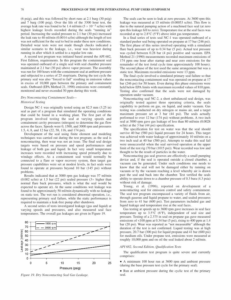
A second series of tests investigated leakage (gas and liquid) atvarying speeds and pressures, and also measured seal facetemperatures. The overall gas leakages are given in Figure 19.
Figure 19. Dry Noncontacting Seal Gas Leakage.
The seals can be seen to leak at zero pressure. At 3600 rpm thisleakage was measured at 15 ml/min (0.00053 scfm). This flow isdue to the natural pumping action of a machined face seal (at zerorpm this leakage fell to zero). Temperature rise at the seal faces wasrecorded at up to 2.8°C (5°F) above inlet gas temperature.
In a final series of tests seal NC-1 was operated outboard of astandard pusher seal being operated on propane at 17 bar (246 psi).The first phase of this series involved operating with a simulatedflare back pressure of up to 0.34 bar (5 psi). Actual test pressurewas cycled between 0.28 bar (4 psi) positive and vacuum. EPAMethod 21 (1990) measurements recorded maximum emissions of174 ppm one hour after startup and near zero emissions for theremainder of the test (total cycle time approximately 100 hours).The second phase of the test used the same arrangement but was astatic test. Maximum recorded emissions were 13 ppm.
The final cycle involved a simulated primary seal failure so thatthe noncontacting containment seal was operated on propane at 17bar (246 psi) for 50 hours. Even during this phase emissions wereheld below EPA limits with maximum recorded values of 810 ppm.Testing also confirmed that the seals were not damaged byoperation under vacuum.
Noncontacting seal NC-2, a short unbalanced seal design, wasoriginally tested against three operating criteria, the sealscapability to perform on gas, on liquid, and under vacuum. Gastesting was conducted on dry nitrogen or mains air, and a targetmaximum pressure set at 3 bar (44 psi). The seals actuallyperformed to over 12 bar (174 psi) without problems. A two inchseal at 3000 rpm gave gas leakage of less than 80 ml/min (0.0028scfm) at the 3 bar (44 psi) specification.
The specification for test on water was that the seal shouldsurvive 40 bar (580 psi) liquid pressure for 24 hours. This targetwas achieved with water leakage of approximately 10 ml/min on atwo inch seal at 40 bar (580 psi). Attempts to make this seal failwere unsuccessful when the seal survived operation at the upperlimit of the test rig (70 bar (1015 psi)). Wear recorded was low andthought to be the result of particles in the water.
Noncontacting gas seal grooves are effectively a small pumpingdevice and, if the seal is operated outside a closed chamber, avacuum can be generated. Under such conditions one needs toknow that the seal will not be damaged either by running onvacuum or by the vacuum reaching a level whereby air is drawnpast the seal and back into the chamber. Test verified the sealsability to operate down to a chamber pressure of 0.3 bara (4.3 psia)without risk of damage.
Young, et al. (1996), reported on development of anoncontacting seal for emission control and safety containment.The seal test program encompassed a variety of fluids from air,through gaseous and liquid propane to water, and sealed pressuresfrom zero to 41 bar (600 psi). Test parameters included gas andliquid leakage and temperature rise at the seal faces.
Gas testing at speeds up to 3600 rpm gave increases in seal facetemperature up to 3.5°C (6°F), independent of seal size andpressure. Testing of a 2.375 in seal on propane gas gave measuredemissions of <100 ppm at 0.34 bar (5 psi), rising to 400 ppm at 1.4bar (20 psi). Wear was reported as “not measurable” although theduration of the test is not confirmed. Liquid testing was at highpressure, 20.7 bar (300 psi) for liquid propane and 41 bar (600 psi)for medium oils. Under propane test, emissions were measured atroughly 10,000 ppm and on oil the seal leaked about 2 ml/min.
API 682, Second Edition, Qualification Tests
The qualification test program is quite severe and currentlycomprises:
• A minimum 100 hour run at 3600 rpm and ambient pressure(during the base pressure test cycle for the primary seal).
• Run at ambient pressure during the cyclic test of the primaryseal.
PROCEEDINGS OF THE 19TH INTERNATIONAL PUMP USERS SYMPOSIUM78
CONTAINMENT SEALS FOR API 682 SECOND EDITION 79
• Run for a minimum of 100 hours at 3600 rpm and a gas pressure(propane) of 0.7 bar (10 psi).
• Static test at 1.8 bar (26 psi) for a minimum five minutes.
• Run for a minimum of 100 hours at 3600 rpm on diesel fuel at2.8 bar (41 psi).
• Static test on diesel fuel at 17 bar (246psi) for a minimum offour hours.
Total test duration was of 300 hours minimum plus the cyclic testprogram.
As containment seals had been developed over a period of years,to varying specifications and market requirements and on differenttest apparatus, it was decided to carry out a series of screeningtests. This would be in advance of the final issue of the API 682Second Edition/ISO 21049 qualification test procedure and wouldcompare performances. The test procedure adopted was chosen toreflect the expected qualification test and provide feedback on thethree critical areas of wear, emissions, and liquid leakage.
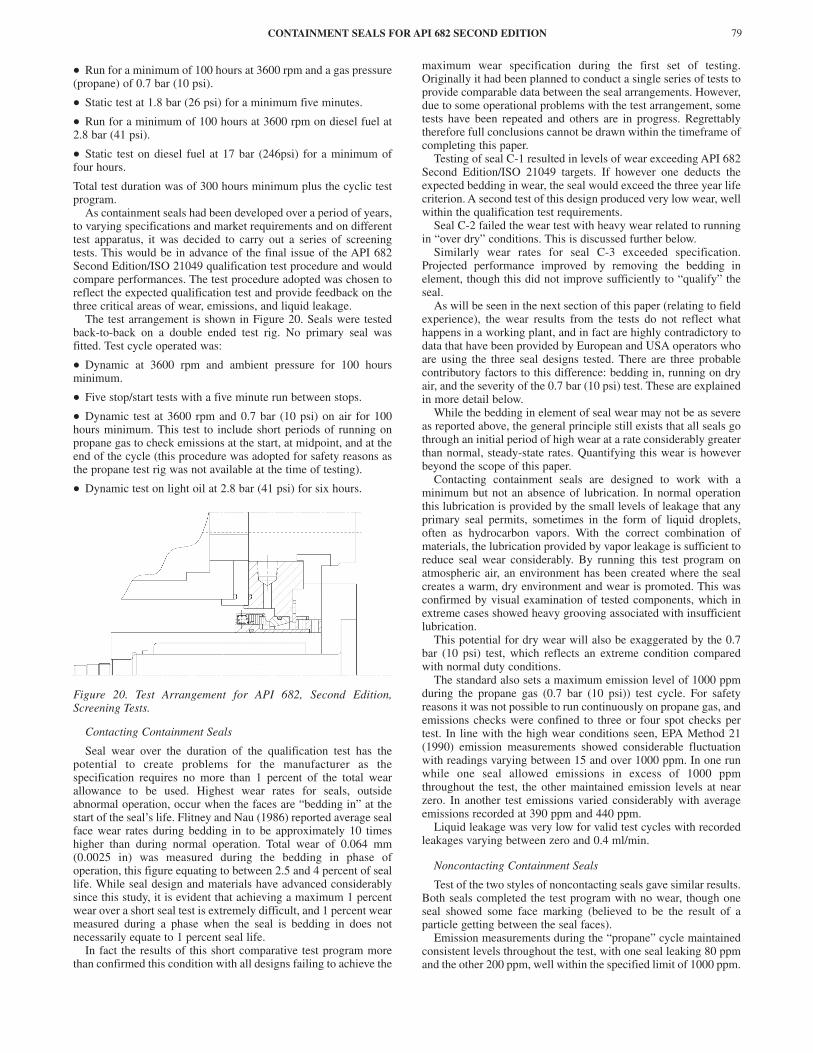
The test arrangement is shown in Figure 20. Seals were testedback-to-back on a double ended test rig. No primary seal wasfitted. Test cycle operated was:
• Dynamic at 3600 rpm and ambient pressure for 100 hoursminimum.
• Five stop/start tests with a five minute run between stops.
• Dynamic test at 3600 rpm and 0.7 bar (10 psi) on air for 100hours minimum. This test to include short periods of running onpropane gas to check emissions at the start, at midpoint, and at theend of the cycle (this procedure was adopted for safety reasons asthe propane test rig was not available at the time of testing).
• Dynamic test on light oil at 2.8 bar (41 psi) for six hours.
Figure 20. Test Arrangement for API 682, Second Edition,Screening Tests.
Contacting Containment Seals
Seal wear over the duration of the qualification test has thepotential to create problems for the manufacturer as thespecification requires no more than 1 percent of the total wearallowance to be used. Highest wear rates for seals, outsideabnormal operation, occur when the faces are “bedding in” at thestart of the seal’s life. Flitney and Nau (1986) reported average sealface wear rates during bedding in to be approximately 10 timeshigher than during normal operation. Total wear of 0.064 mm(0.0025 in) was measured during the bedding in phase ofoperation, this figure equating to between 2.5 and 4 percent of seallife. While seal design and materials have advanced considerablysince this study, it is evident that achieving a maximum 1 percentwear over a short seal test is extremely difficult, and 1 percent wearmeasured during a phase when the seal is bedding in does notnecessarily equate to 1 percent seal life.
In fact the results of this short comparative test program morethan confirmed this condition with all designs failing to achieve the
maximum wear specification during the first set of testing.Originally it had been planned to conduct a single series of tests toprovide comparable data between the seal arrangements. However,due to some operational problems with the test arrangement, sometests have been repeated and others are in progress. Regrettablytherefore full conclusions cannot be drawn within the timeframe ofcompleting this paper.
Testing of seal C-1 resulted in levels of wear exceeding API 682Second Edition/ISO 21049 targets. If however one deducts theexpected bedding in wear, the seal would exceed the three year lifecriterion. A second test of this design produced very low wear, wellwithin the qualification test requirements.
Seal C-2 failed the wear test with heavy wear related to runningin “over dry” conditions. This is discussed further below.
Similarly wear rates for seal C-3 exceeded specification.Projected performance improved by removing the bedding inelement, though this did not improve sufficiently to “qualify” theseal.
As will be seen in the next section of this paper (relating to fieldexperience), the wear results from the tests do not reflect whathappens in a working plant, and in fact are highly contradictory todata that have been provided by European and USA operators whoare using the three seal designs tested. There are three probablecontributory factors to this difference: bedding in, running on dryair, and the severity of the 0.7 bar (10 psi) test. These are explainedin more detail below.
While the bedding in element of seal wear may not be as severeas reported above, the general principle still exists that all seals gothrough an initial period of high wear at a rate considerably greaterthan normal, steady-state rates. Quantifying this wear is howeverbeyond the scope of this paper.
Contacting containment seals are designed to work with aminimum but not an absence of lubrication. In normal operationthis lubrication is provided by the small levels of leakage that anyprimary seal permits, sometimes in the form of liquid droplets,often as hydrocarbon vapors. With the correct combination ofmaterials, the lubrication provided by vapor leakage is sufficient toreduce seal wear considerably. By running this test program onatmospheric air, an environment has been created where the sealcreates a warm, dry environment and wear is promoted. This wasconfirmed by visual examination of tested components, which inextreme cases showed heavy grooving associated with insufficientlubrication.
This potential for dry wear will also be exaggerated by the 0.7bar (10 psi) test, which reflects an extreme condition comparedwith normal duty conditions.
The standard also sets a maximum emission level of 1000 ppmduring the propane gas (0.7 bar (10 psi)) test cycle. For safetyreasons it was not possible to run continuously on propane gas, andemissions checks were confined to three or four spot checks pertest. In line with the high wear conditions seen, EPA Method 21(1990) emission measurements showed considerable fluctuationwith readings varying between 15 and over 1000 ppm. In one runwhile one seal allowed emissions in excess of 1000 ppmthroughout the test, the other maintained emission levels at nearzero. In another test emissions varied considerably with averageemissions recorded at 390 ppm and 440 ppm.
Liquid leakage was very low for valid test cycles with recordedleakages varying between zero and 0.4 ml/min.
Noncontacting Containment Seals
Test of the two styles of noncontacting seals gave similar results.Both seals completed the test program with no wear, though oneseal showed some face marking (believed to be the result of aparticle getting between the seal faces).
Emission measurements during the “propane” cycle maintainedconsistent levels throughout the test, with one seal leaking 80 ppmand the other 200 ppm, well within the specified limit of 1000 ppm.
The qualification test minimum performance requirements onlyrequire liquid leakage from the containment seal to be recordedand does not specify acceptable leakage levels. Leakages recordedwere consistent with levels experienced during originaldevelopment program (refer to section “Dry (Gas Lubricated)Mechanical Seals” above).
Clearly the results to date indicate that noncontacting seals willpass API 682 Second Edition/ISO 21049 qualification tests,whereas dry contacting seals may not successfully achieve thewear requirement. Evaluation tests are ongoing to establish if anyone of the listed reasons dominate the cause of this occurrence, andthe results of this work will be presented when available.
SECONDARY CONTAINMENT—FIELD EXPERIENCE AND EVOLUTIONOF SELECTED CONTAINMENT SEALS
Dry Contacting Containment Seals
The dry running containment seals included in this operationalreview have been applied extensively across a broad base ofindustries and duties. Design C-1 has been supplied as part of a“standard API cartridge” in tandem with API 682, First Edition,qualified single seals and in “engineered cartridges” for designsusing alternative pusher seals. Design C-2 has been supplied aspart of a “standard API cartridge” in tandem with API 682 qualifiedsingle seals, in “engineered cartridges” using alternative pusherand bellows seals, and as a “bolt-on” assembly. Design C-3 hasbeen supplied as part of an “engineered cartridge” in tandem withAPI 682 qualified bellows and as a “bolt-on” assembly usingalternative pusher and bellows seals.
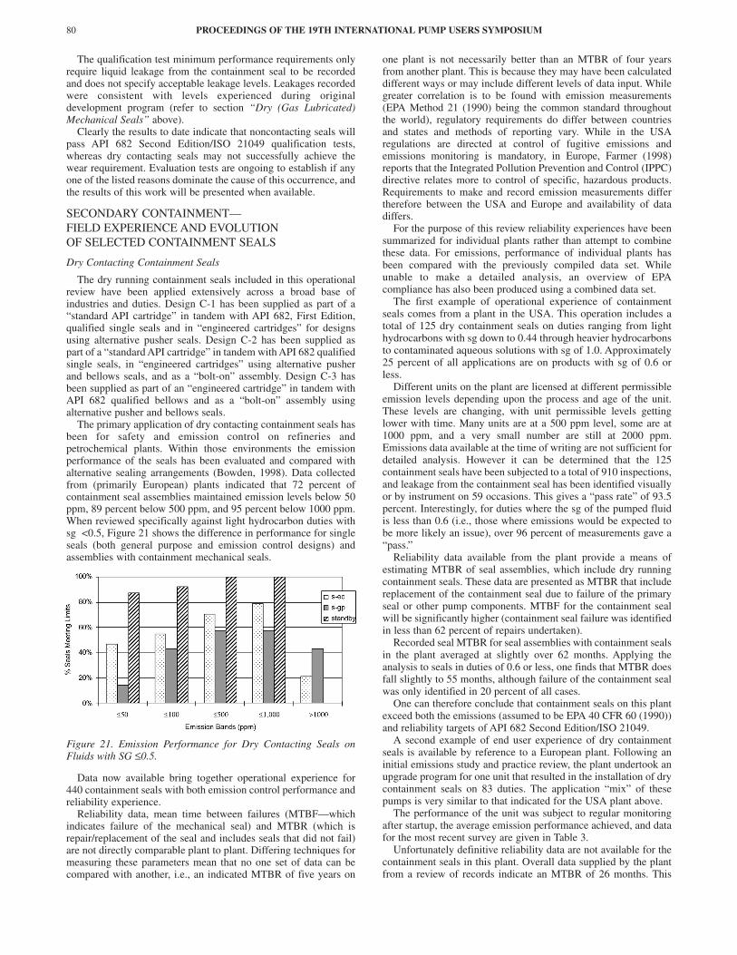
The primary application of dry contacting containment seals hasbeen for safety and emission control on refineries andpetrochemical plants. Within those environments the emissionperformance of the seals has been evaluated and compared withalternative sealing arrangements (Bowden, 1998). Data collectedfrom (primarily European) plants indicated that 72 percent ofcontainment seal assemblies maintained emission levels below 50ppm, 89 percent below 500 ppm, and 95 percent below 1000 ppm.When reviewed specifically against light hydrocarbon duties withsg <0.5, Figure 21 shows the difference in performance for singleseals (both general purpose and emission control designs) andassemblies with containment mechanical seals.
Figure 21. Emission Performance for Dry Contacting Seals onFluids with SG ≤0.5.
Data now available bring together operational experience for440 containment seals with both emission control performance andreliability experience.
Reliability data, mean time between failures (MTBF—whichindicates failure of the mechanical seal) and MTBR (which isrepair/replacement of the seal and includes seals that did not fail)are not directly comparable plant to plant. Differing techniques formeasuring these parameters mean that no one set of data can becompared with another, i.e., an indicated MTBR of five years on
one plant is not necessarily better than an MTBR of four yearsfrom another plant. This is because they may have been calculateddifferent ways or may include different levels of data input. Whilegreater correlation is to be found with emission measurements(EPA Method 21 (1990) being the common standard throughoutthe world), regulatory requirements do differ between countriesand states and methods of reporting vary. While in the USAregulations are directed at control of fugitive emissions andemissions monitoring is mandatory, in Europe, Farmer (1998)reports that the Integrated Pollution Prevention and Control (IPPC)directive relates more to control of specific, hazardous products.Requirements to make and record emission measurements differtherefore between the USA and Europe and availability of datadiffers.
For the purpose of this review reliability experiences have beensummarized for individual plants rather than attempt to combinethese data. For emissions, performance of individual plants hasbeen compared with the previously compiled data set. Whileunable to make a detailed analysis, an overview of EPAcompliance has also been produced using a combined data set.
The first example of operational experience of containmentseals comes from a plant in the USA. This operation includes atotal of 125 dry containment seals on duties ranging from lighthydrocarbons with sg down to 0.44 through heavier hydrocarbonsto contaminated aqueous solutions with sg of 1.0. Approximately25 percent of all applications are on products with sg of 0.6 orless.
Different units on the plant are licensed at different permissibleemission levels depending upon the process and age of the unit.These levels are changing, with unit permissible levels gettinglower with time. Many units are at a 500 ppm level, some are at1000 ppm, and a very small number are still at 2000 ppm.Emissions data available at the time of writing are not sufficient fordetailed analysis. However it can be determined that the 125containment seals have been subjected to a total of 910 inspections,and leakage from the containment seal has been identified visuallyor by instrument on 59 occasions. This gives a “pass rate” of 93.5percent. Interestingly, for duties where the sg of the pumped fluidis less than 0.6 (i.e., those where emissions would be expected tobe more likely an issue), over 96 percent of measurements gave a“pass.”
Reliability data available from the plant provide a means ofestimating MTBR of seal assemblies, which include dry runningcontainment seals. These data are presented as MTBR that includereplacement of the containment seal due to failure of the primaryseal or other pump components. MTBF for the containment sealwill be significantly higher (containment seal failure was identifiedin less than 62 percent of repairs undertaken).
Recorded seal MTBR for seal assemblies with containment sealsin the plant averaged at slightly over 62 months. Applying theanalysis to seals in duties of 0.6 or less, one finds that MTBR doesfall slightly to 55 months, although failure of the containment sealwas only identified in 20 percent of all cases.
One can therefore conclude that containment seals on this plantexceed both the emissions (assumed to be EPA 40 CFR 60 (1990))and reliability targets of API 682 Second Edition/ISO 21049.
A second example of end user experience of dry containmentseals is available by reference to a European plant. Following aninitial emissions study and practice review, the plant undertook anupgrade program for one unit that resulted in the installation of drycontainment seals on 83 duties. The application “mix” of thesepumps is very similar to that indicated for the USA plant above.
The performance of the unit was subject to regular monitoringafter startup, the average emission performance achieved, and datafor the most recent survey are given in Table 3.
Unfortunately definitive reliability data are not available for thecontainment seals in this plant. Overall data supplied by the plantfrom a review of records indicate an MTBR of 26 months. This
PROCEEDINGS OF THE 19TH INTERNATIONAL PUMP USERS SYMPOSIUM80

CONTAINMENT SEALS FOR API 682 SECOND EDITION 81
Table 3. Emission Performance of Dry Contacting Seals in aProcess Plant in Europe.
figure however includes failure of not only the primary andcontainment seals but all pump components, e.g., bearings,operational failures, etc., and therefore reflects seal maintenance orrepair undertaken for any reason. Many of the pumps indicateMTBRs of just a few months and in some cases less than onemonth. It is believed that the figures presented do not accuratelyreflect seal reliability in the plant, particularly as the plant iscontinuing to upgrade single seals (to date 109 mechanicalcontainment seals have been installed).
A third example of operational experience comes from the AsiaPacific region. This is of particular interest as the plant was builtusing seals designed to comply with API 682, First Edition. Whilethis did not include direct provision for containment seals, a totalof 67 have been supplied as engineered arrangements having beentested generally to API 682, First Edition, standards prior toshipment.
Of the 67 seals, 28 percent are on applications with a pumpedfluid having a sg of 0.6 or less (so similar to the above plants,though only 16 percent of applications are for sg’s above 0.8).Mechanical containment seals are therefore primarily used on lightto medium hydrocarbon duties in the plant. As local regulations donot require emissions monitoring, no specific measurement dataare available.
Since startup in mid 1996, the plant has repaired/replacedcontainment seals on 78 occasions. Replacement has been carriedout on failure of the primary seal, containment seal, and as requiredfor other pump components, so we again have an MTBR for theseal assembly rather than an MTBF for the seal or containmentseal. This MTBR works out at 46 months exceeding the target setwithin API 682. The trend of failures in the plant does howeverindicate that the MTBR of the mechanical containment seals isincreasing. Wallace, et al. (1999), reported on a reliability programthat had been undertaken involving both plant and supplierpersonnel. In this program a team comprising operations,maintenance, integrated maintenance inspection (IMI), and the sealvendor reviewed failures, identified causes, and recommendedsolutions. At the time the team was formed, overall seal MTBRwas less than three years. Latest data indicate that this has risen toover 12 years. This improvement can be seen in an analysis ofcontainment seal assembly replacements. Following startup fiveand a half years ago, 22 percent of seal repair or replacements weremade in the first six months of plant operation, and 77 percentoccurred during the first two and a half years. If the calculationwere started from January 1, 1999, one would get an MTBR ofnearly 10 years for the containment seal assemblies! While thisfigure is clearly distorted by the measurement period, thedistribution of failures (over three-fourths of replacements in thefirst half of the measurement period) clearly indicates MTBRimproving beyond the current 46 months.
Data from the European and Asia plants perhaps sends a strongmessage. While API 682 is clearly a very important standard thathas made a positive contribution to seal performance, it is not a “fitand forget” solution. Continued performance improvements arebest maintained by installing the right solution and initiating anongoing program to continue to improve.
API 682 is naturally based on improving performance ofmechanical seals during normal working conditions, in the case ofcontainment seals “normal” performance can be consideredbeyond a long backup life and the question asked how well does itfunction if the primary seal fails? Bowden (1995) reported on fieldexperience with a limited number of seal assemblies where partial
or complete failure of the primary seal had occurred and the levelsof emission control being maintained by the containment seal(Table 4).
Table 4. Dry Contacting Seal—Emission Control on Primary SealFailure.
In the case of the isobutane application a serious failure of theprimary seal has occurred but, as with the other applications,emissions are maintained within EPA limits.
Some other experiences reported from field experience aresummarized below. These experiences are necessarily brief asequipment is normally shut down within a relatively short time ofdiscovering primary seal failure.
• A USA pipeline operator reported a process upset caused failureof the primary seal after two years’ operation. The containmentseal held process fluid at 55 bar (800 psi), permitting a controlledpump shutdown.
• A European oil company reported failure of a primary sealleading to activation of the pressure alarm. The pump could not beshut down immediately and continued to operate under alarm fortwo months without leakage until shut down was possible.
• A USA operator reports failure of the primary seal, which wouldnormally have required pump shut down, but by running on thecontainment seal it was possible to keep the pump in service forover one week to prior maintenance.
Dry Noncontacting Containment Seals
The noncontacting containment seal is a comparatively newproduct compared with the contacting design. Field experience istherefore much less available and detailed—in the seal business itis often the case that the only time you hear of a problem is whenthings are going wrong!
The dry noncontacting seal is generally used for gaseous ratherthan liquid or mixed phase fluids and is especially favored forflammable environments where auto-ignition is a concern.Although plantwide use has been made of noncontactingcontainment seals many have been supplied in small numbers atindividual plants, often on applications where other seal designshave performed poorly. Once the seal is installed, operating focustends to move to the next problem and close monitoring reduces.
As detailed reliability and emissions data are not readilyavailable, in this section the authors will therefore confine thereview to some specific application experiences.
In the Middle East noncontacting containment seals weresupplied for six pumps in liquified petroleum gas (LPG) service(deethanizer reflux fluid sg 0.4 and debutanizer reflux fluid sg0.45). These are high-pressure services over 33 bar (479 psi)suction pressure with low pressure differentials (37 bar (537 psi)discharge). Following supply, over four years ago the primary sealsuffered a number of failures relating to flush and installationproblems. Following initial resolution of these issues the drynoncontacting containment seals have performed without problemsdespite occasional ongoing problems with the seal flush, whichhave led to some running difficulties with the primary seals.
At the same plant, four noncontacting containment seals of thesame design have been installed on debutanizer overhead duties (sg0.496). These applications are a little less severe and consequentlythere have been no operating problems. The seals have been inoperation for over three years without problems.
Emissions Recorded Overall Performance Last Survey100 ppm or less 75.2% 83.8%500 ppm or less 86.0% 90.3%1000 ppm or less 94.3% 96.8%over 1000 ppm 5.7% 3.2%
Fluid Pressurebar (psi)
Fluids.g.
Temp.ºC (ºF)
Containmentcavity pressure
bar (psi)
Emissionsppm
Isobutane 1.72 (25) 0.58 16 (61) 5.9 0Propane/ butane 17.2 (250) 0.52 43 (109) 0.5 218Lt hydrocarbons 14.6 (212) 0.46 43 (109) 0.14 295
LPG 15 (218) 0.52 15 (59) >10,000 ppm 0LPG 22.9 (332) 0.44 41 (106) >10,000 ppm 0

A plant in Germany is operating noncontacting containmentseals on ammonia (99 percent) at 22 bar (319 psi) and �34°C(�29°F). This arrangement was installed to replace a drycontacting containment seal that was suffering from heavy wearand failing between two weeks and six months. The seals are beingrun without a nitrogen flush. The noncontacting seals have nowbeen running for two years without problem.
Noncontacting seals are being used on a refinery in France onpropylene (sg 0.45) duties. Emission measurements have beenmade on these seals and found to be below 100 ppm without theapplication of a nitrogen (or other inert gas) buffer gas. Generallythe seals are removed from service soon after failure of the primaryseal. They have however been operated up to three days withoutproblems when required.
Young, et al. (1996), reported on field experience with a drynoncontacting containment seal on a plant in France. Operatingexperience was limited but primary seal failure on one pump in 28bar (400 psi) methane/ethane service had occurred, and thecontainment seal had run for three hours leak-free until shut down.
SECONDARY CONTAINMENT—PERFORMANCE SUMMARIZED ANDCOMPARED WITH LIQUID BARRIER/BUFFER DUAL SEALS
As indicated earlier, data included in this paper come from avariety of test programs that were undertaken at varying times. Thecapability to make direct comparisons is therefore somewhatlimited. Equally field data, while invaluable as an indicator toperformance under real life conditions, will vary with regulatoryand operational practices across continents and operators. Anyattempt to compare must therefore be recognized as offering onlyan outline guide rather than a definitive comparison.
The two fundamentals sought by API 682 are long life andemission control. Comparison shall therefore be restricted betweenthose two sets of data. As much of the test work was conducted“preemissions” then leakages were either not measured directly orwere quoted in varying units. Within the paper are examples of gasleakages quoted in ml/min. These can be converted to approximateppm figures using Equation (1):
(1)
where SV = screening value in ppm.This formula is derived from the US EPA and work carried out
in the CMA/STLE joint study (European Sealing Association,1995).
Conversion of gm/hr to ml/min was calculated using Equation (2).
(2)
where ρ = gas density and is assumed as propane at 1.97 gm/l.For contacting containment seals one consistently sees low
emission levels recorded and this is shown in Table 5.
Table 5. Inhouse Testing—Emission Levels for Dry ContactingSeals.
With the exception of the 2.1 bar (30 psi) test on seal C-3, allemissions recorded were very low. Testing on C-2 involved manysamples with most measurements below 10 ppm but 77 ppm beingthe highest recorded. For noncontacting seals one sees leakage datagenerally higher with quite a large scatter. This is shown in Table 6.
Table 6. Inhouse Testing—Emission Levels for Dry NoncontactingSeals.
If performance is compared at a flare back pressure of 0.5 bar (7psi) the contacting containment seal indicates that it will limitemissions to <50 ppm, while the noncontacting seal would beexpected to permit emission levels of perhaps 200 to 300 ppm.Attempting to relate this performance to field experience,measurements show that from the original survey work over 70percent of containment seals leaked less than 50 ppm. The latestdata from the Italian plant indicated that nearly 80 percent achievedthis performance indicating a good level of correlation.Unfortunately insufficient data are available for noncontactingseals to permit similar comparison.
Kittleman, et al. (1994), reported the findings of seal surveywork for the CMA/STLE Pump Seal Mass Emissions Study.Within the study were emission measurements on 44 double seals(no differentiation was made between pressurized andunpressurized dual seals), which reported that one seal out of the44 exceeded an emission limit of 1000 ppm. Fone (1993) reportedfield emission measurements on 27 dual seals (four pressurized, 37unpressurized) following periods of six and 12 months inoperation. All measurements were of less than 1000 ppm. Bowden(1998) reported field emission measurements on 127 dual seals (19pressurized and 108 unpressurized) with only one seal from thesample exceeding 1000 ppm. Combining the latter two reports,which contain sufficient detail for analysis, the overallperformance of 154 dual seal measurements can be summarized inTable 7.
Table 7. Field Emission Performance of Dual (Pressurized andUnpressurized) Seals.
Bowden (1998) also reported on the field emission performanceof 201 single seals with dry containment seal (dry tandem). Theresults of this survey are summarized in Table 8.
Table 8. Field Emission Performance of Dry Containment Seal.
These data on containment seals have now been updatedincluding field data on a further 239 seals (although not with fullemission records for all seals). Containment seal performancesderived can be summarized in Table 9.
Table 9. Field Emission Performance for Dry Containment Seals—Extended Data Set.
The combined data set for containment seals therefore gives us93.8 percent of mechanical containment seals meeting current EPAemission targets.
PROCEEDINGS OF THE 19TH INTERNATIONAL PUMP USERS SYMPOSIUM82
Leakrate gm hr SV/ . ( ) .= 0 02784 0 733
gm hr ml/ /min /= × ×60 1000ρ
Containmentcavitypressurebar (psi)
10000ppm
0(0)
0(0)
0.3(4.3)
1.7(25)
2.1(30)
17(247)
Emissionsmeasuredppm
<50 11 3 to 77 0 <10 1080 0
Containmentcavitypressurebar (psi)
0(0)
0.28(4)
0.34(5)
1.4(20)
1.5(22)
3(44)
Emissionsmeasuredppm
285 174 100 400 1748 2772
≤ 50 ppm ≤ 100 ppm ≤ 500 ppm ≤ 1000 ppm > 1000 ppmQty 141 147 152 153 1% 91.5% 95.5% 98.7% 99.4% 0.6%
≤ 50 ppm ≤ 100 ppm ≤ 500 ppm ≤ 1000 ppm > 1000 ppmQty 144 156 178 191 10% 71.6% 77.6% 88.6% 95.0% 5.0%
* Data available only records EPA pass or fail, while some data is for an EPA limit of500 PPM it has been assumed that all are at 1000 PPM for this comparison
≤ 100 ppm ≤ 500 ppm ≤ 1000 ppm > 1000 ppmItalian plant overall 75.2% 86.0% 94.3% 5.7%Italian plant (latest) 83.8% 90.3% 96.8% 3.2%
USA plants * 93.5% 6.5%

CONTAINMENT SEALS FOR API 682 SECOND EDITION 83
Comparative data for reliability between dual contacting wet sealswith an unpressurized buffer and dry mechanical containment sealsare not available. Indeed differing methods of calculation forindividual plants makes compilation of an overall data set impossible.Reliability data available have however given MTBR performance fordry containment seals of 62 months for one USA plant, 26 months foran Italian plant (data suspect), and 46 months for an Asian plant. Withthe exception of the Italian data, MTBR figures are well above thetarget set in API 682. Since the figures include seal replacements dueto nonseal problems, it can be concluded that containment seal MTBFfigures are considerably higher.
Cost of Ownership
If, as the data indicate, typical MTBRs for dry mechanicalcontainment seals are around five years, then it is reasonable tosuggest that they are not far behind conventional dual contactingwet seals in operational life. So are they a real option for modernprocess plants? It is well beyond the scope of this paper to attemptto identify when applications demand a dual contacting wet sealwith unpressurized buffer to be installed, but if just duties areconsidered where a dry mechanical containment seal is an option,does this offer the operator savings?
Data compiled with the help of major US operators in recentyears indicate that it can. A typical (rounded) purchase cost for abasic API Plan 52 seal system comprising vessel, instrumentation,valves, pipework, and support has been calculated at $2900. Incomparison a typical Plan 76 system would cost $1150.Installation of the Plan 52 calculates at $500 while the Plan 76 is$200. Cost of operation including barrier fluids, cooling water, androutine maintenance costs $950 for the Plan 52 compared with$100 for the Plan 76.
Thus savings from the cost of ownership can be estimated as oneoff installation savings of $2000 with annual savings of $850.
CONCLUSIONS AND RECOMMENDATIONS
Operational experience combined with ongoing improvementsin containment seal design and performance has led to recognitionof the capabilities of containment seals and their inclusion in API682 Second Edition/ISO 21049. Both inhouse testing and moreimportantly operational experience have verified the capability ofcontainment seals to exceed the performance targets in API 682,although this capability has failed to be confirmed by the recenttest program, which requires further investigation.
• Dry contacting containment seals:
• Provide emission control to very high levels with over 70percent achieving <50 ppm and approximately 95 percent <1000ppm.
• Will seal high pressure liquids but have limited capabilities onhigh pressure gas.
• Can maintain emissions well below EPA levels in the event ofprimary seal failure.
• Provide effective leakage containment of liquids, gases, andfluid mixtures.
• Have reported MTBRs of four to five years.
• Have lower installation and operational costs than dual(liquid) seals.
• Dry noncontacting containment seals:
• Give better performance on high gas pressures.
• Are more tolerant of pressure variations when the seal isconnected to flare.
• Give negligible wear.
• Achieve low levels of dynamic leakage (well within EPAlimits).
• Can maintain emissions well below EPA levels in the event ofprimary seal failure.
• Are the default selection in API 682 Second Edition/ISO21049.
System piping diagrams have been updated with the inclusion ofnew plans for containment (and pressurized gas) seals in API 682Second Edition/ISO 21049.
Application of buffer gas systems can be made where emissionof process gas to atmosphere must be minimized (e.g., when H2Scontaminated) or where additional containment is desired onfailure of the primary seal. They can also be applied whenadditional protection is required for the containment seal facesfrom primary seal leakage. When the seal is operated at belowfreezing temperatures the buffer is better applied outboard of theseal faces.
Operators may choose to deviate from standard systems to meettheir own operational preferences and requirements. It isrecommended that application of some key elements of the systemare always considered:
• Pressure indicators are important for visual checks on sealintegrity and for condition testing.
• Alarms (either pressure or flow dependent on the nature ofleakage) are important for safety and to give warning of possibleseal problems.
• Test connections will facilitate condition monitoring that willprovide advance warning of performance deterioration.
• Orifices are interconnected with alarm systems but may besized differently by operators relative to their experiences. Correctsizing should be determined by consideration of the nature of thefluid that will pass through the orifice and the potential forblockage.
• Check valves have been the source for some operating reliabilityproblems and are often excluded, leading to the potential forbackflow from the flare to the seal. An option is to site the valvesome distance from the rotating equipment and above the level ofthe flare system manifold.
REFERENCES
API Standard 610, Eighth Edition, 1995, “Centrifugal Pumps forPetroleum, Heavy Duty Chemical and Gas Industry Services,”American Petroleum Institute, Washington, D.C.
API Standard 682, First Edition, 1992, “Shaft Sealing Systems forCentrifugal and Rotary Pumps,” American Petroleum Institute,Washington, D.C.
API 682 Second Edition/ISO 21049, Draft, 2001, “Shaft SealingSystems for Centrifugal and Rotary Pumps,” AmericanPetroleum Institute, Washington, D.C.; InternationalOrganization for Standardization, Geneva, Switzerland.
Bowden, P. E., 1995, “Cost Effective Emission Control—TheEuropean Experience,” Proceedings of the First EuropeanConference on Controlling Fugitive Emissions from Valves,Pumps and Flanges, Antwerp, Belgium, pp. 185-208.
Bowden, P. E., 1998, “Continuing Development of MechanicalSeals for High Reliability and Very Low Emissions,”Proceedings of the Second European Fugitive EmissionsConference—Controlling Leaks from Valves, Pumps andFlanges, Dusseldorf, Germany, pp. 95-114.
EPA Method 21, 1990 Clean Air Act, 1990, U.S. FederalRegulation 40 CFR 60, 1990, “Determination of VolatileOrganic Compound Leaks,” Reference Method 21, AppendixA, United States Environmental Protection Agency,Washington, D.C.

European Sealing Association, 1995, “Meeting EmissionLegislation Requirements with Today’s Advanced TechnologySealing Systems ESA 005/95,” Proceedings of the FirstEuropean Conference on Controlling Fugitive Emissions fromValves, Pumps and Flanges, Antwerp, Belgium, Appendix II.
Farmer, A. M., 1998, “Tackling Fugitive Emissions: A EuropeanPerspective,” Proceedings of the Second European FugitiveEmissions Conference—Controlling Leaks from Valves, Pumpsand Flanges, Dusseldorf, Germany, pp. 1-12.
Flitney, R. K. and Nau, B. S., 1986, “A Study of Factors AffectingMechanical Seal Performance,” Proceedings of the Institutionof Mechanical Engineers, 200, (107), London, England.
Fone, C. J., 1993, “Effectively Managing Your Pump SealEmissions,” Pump Performance and Reliability Conference,Aberdeen, Scotland.
Fone, C. J., 1995, “The Application of Innovation and Technologyto the Containment of Pump Shaft Seal Emissions,”Proceedings of the First European Conference on ControllingFugitive Emissions from Valves, Pumps and Flanges, Antwerp,Belgium, pp. 175-184.
Kittleman, T., Pope, M., and Adams, W. V., 1994, “CMA/STLEPump Seal Mass Emissions Study,” Proceedings of theEleventh International Pump Users Symposium,Turbomachinery Laboratory, Texas A&M University, CollegeStation, Texas, pp. 57-62.
Wallace, N. M., David, T. J., and Bowden, P. E., 1999,“Quantifying Reliability Improvements Through EffectivePump Seal and Coupling Management,” Proceedings of theEighth International Process Plant Reliability Conference,Houston, Texas.
Young, L. A., Key, W. E., and Grace, R. L., 1996, “Development ofa Noncontacting Seal for Gas/Liquid Applications Using WavyFace Technology,” Proceedings of the Thirteenth InternationalPump Users Symposium, Turbomachinery Laboratory, TexasA&M University, College Station, Texas, pp. 39-45.
BIBLIOGRAPHY
Flach, P. M., Sandgren, J. E., and Casucci, D. P., 1993,“Controlling Emissions to Atmosphere Through the Use of aDry-Sliding Secondary Containment Seal,” Proceedings of theTenth International Pump Users Symposium, TurbomachineryLaboratory, Texas A&M University, College Station, Texas,pp. 55-61.
Institution of Mechanical Engineers, 1998, “Mechanical SealPractice for Improved Performance,” London, England/Mechanical Engineering Publications Ltd.
STLE SP-30, Revised April 1994, “Guidelines for MeetingEmission Regulations for Rotating Machinery withMechanical Seals,” Society of Tribologists and LubricationEngineers, Park Ridge, Illinois.
ACKNOWLEDGEMENTS
The authors would like to thank the management of AllianceRefining Company, Map Ta Phut, Thailand; Enichem(Petrochemical), Sarroch, Italy; Koch Refinery, Corpus Christi,Texas; Valero Refinery, Paulsboro, New Jersey; and other USA andEuropean refineries for their permission to include data from theirplants in this paper.
The authors would also like to thank Alfredo Degli Antoni, JohnChoma, Skip Kretchsmar, and Pasquale Zeolla of John Crane USAand Italy for their invaluable assistance in collecting data.
PROCEEDINGS OF THE 19TH INTERNATIONAL PUMP USERS SYMPOSIUM84