Embed Size (px)
Citation preview

CONTACT! ISSUE 80 PAGE 1

CONTACT! ISSUE 80 PAGE 2
MISSION CONTACT! Magazine is published bi-monthly by Aeronautics Education Enterprises (AEE), an Arizona nonprofit corporation, established in 1990 to promote aeronautical education. CONTACT! promotes the experimental development, expan-sion and exchange of aeronautical concepts, information, and experience. In this corporate age of task specialization many individuals have cho-sen to seek fresh, unencumbered avenues in the pursuit of improvements in aircraft and power-plants. In so doing, they have revitalized the pro-gress of aeronautical design, particularly in the general aviation area. Flight efficiency improve-ments, in terms of operating costs as well as airframe drag, have come from these efforts. We fully expect that such individual efforts will con-tinue and that they will provide additional incen-tives for the advancement of aeronautics.
EDITORIAL POLICY CONTACT! pages are open to the publication of these individual efforts. Views expressed are exclusively those of the individual authors. Ex-perimenters are encouraged to submit articles and photos of their work. Materials exclusive to CONTACT! are welcome but are returnable only if accompanied by return postage. Every effort will be made to balance articles reporting on com-mercial developments. Commercial advertising is not accepted. All rights with respect to reproduc-tion, are reserved. Nothing whole or in part may be reproduced without the permission of the pub-lisher.
SUBSCRIPTIONS Six issue subscription in U.S. funds is $24.00 for USA, $28.00 for Canada and Mexico, $40.00 for overseas air orders. CONTACT! is mailed to U.S. addresses at nonprofit organization rates mid January, March, May, July, September and No-vember. Please allow time for processing and delivery of first issue from time of order.
ADDRESS CHANGES / RENEWALS The first line of your label contains the number of your last issue. Please check label for correct-ness. This magazine does not forward. Please notify us of your date of address change consis-tent with our bimonthly mailing dates to avoid missing any issues.
COPYRIGHT 2005 BY AEE, Inc.
PO BOX 1382 Hanford CA 93232-1382
United States of America 559-584-3306
Volume 14 Number 2 Mar– Sep 2005
Issue #80
On the cover: John Thompson’s Kitfox over California’s Central Valley. Photo by Pat Panzera. Special thanks to Don McKinney of Hanford, CA, for providing the photo plane, a beautiful Aeronca Super Decathlon.
3 Revmaster R-3000 Engine 10 years in the making, this new engine is about to hit the market and
take the 100hp engine genre by storm. By John P Moyle
12 Meet Joe Horvath A brief sidebar on Joe and his background with the VW engine By John P Moyle 13 Revflow: Innovations and improvements
Descriptions and details of the inner-workings of the Revflow vari-able-jet, injector carburetor.
By Joe Horvath
15 How fast are you really going? A whimsical look at the effect of stagnation temperature rise as speed increases and how that may be misleading you into believing that you are going faster than you really are. By Paul Lipps
16 The BMW R1100RS Motorcycle engine Mysluk, Konstancin of Poland, reports on his direct experience with converting and flying behind this elegant motorcycle engine.
20 Planning Your Charitable Giving CONTACT! Magazine supporter Percy Lorie III offers a little food for thought by way of the second in his series of informative articles.
23 John O. Thompson's EA-81 powered Kitfox IV-1200 John Thompson’s story of converting a Subaru EA-81and fitting it into
the nose of his beautiful Kitfox. By John P Moyle
The Loss of a Grand Gentleman; A tribute to M.C. “Bill” Harrold By Jess Meyers
I’m writing this from the “comfort” of a coach class, California-bound, American Airlines MD-80, after spending a week in Lakeland, FL, AKA Sun ’n Fun 2005. This is my third year attending SnF, and it was by far the best experience to date. Perhaps the biggest reason it went well for me was that this is the first year that I had full-time help in the booth. During the two previous years, I went solo to the event and
Continued on page 22 From left to right: Associate Edi-tor John P. Moyle and Managing Editor Patrick Panzera manning the CONTACT! Magazine booth at Sun ’n Fun 2005
CONTACT! ISSUE 80 PAGE 3
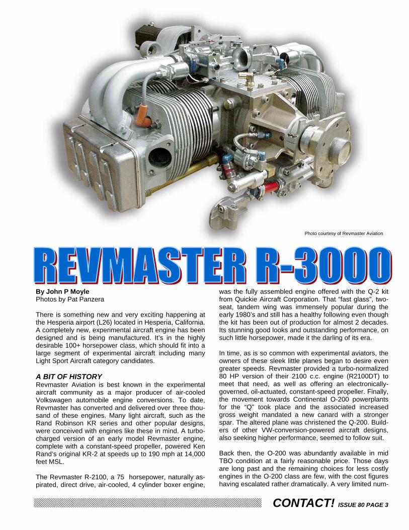
By John P Moyle Photos by Pat Panzera There is something new and very exciting happening at the Hesperia airport (L26) located in Hesperia, California. A completely new, experimental aircraft engine has been designed and is being manufactured. It’s in the highly desirable 100+ horsepower class, which should fit into a large segment of experimental aircraft including many Light Sport Aircraft category candidates. A BIT OF HISTORY Revmaster Aviation is best known in the experimental aircraft community as a major producer of air-cooled Volkswagen automobile engine conversions. To date, Revmaster has converted and delivered over three thou-sand of these engines. Many light aircraft, such as the Rand Robinson KR series and other popular designs, were conceived with engines like these in mind. A turbo-charged version of an early model Revmaster engine, complete with a constant-speed propeller, powered Ken Rand’s original KR-2 at speeds up to 190 mph at 14,000 feet MSL. The Revmaster R-2100, a 75 horsepower, naturally as-pirated, direct drive, air-cooled, 4 cylinder boxer engine,
was the fully assembled engine offered with the Q-2 kit from Quickie Aircraft Corporation. That “fast glass”, two-seat, tandem wing was immensely popular during the early 1980’s and still has a healthy following even though the kit has been out of production for almost 2 decades. Its stunning good looks and outstanding performance, on such little horsepower, made it the darling of its era. In time, as is so common with experimental aviators, the owners of these sleek little planes began to desire even greater speeds. Revmaster provided a turbo-normalized 80 HP version of their 2100 c.c. engine (R2100DT) to meet that need, as well as offering an electronically-governed, oil-actuated, constant-speed propeller. Finally, the movement towards Continental O-200 powerplants for the “Q” took place and the associated increased gross weight mandated a new canard with a stronger spar. The altered plane was christened the Q-200. Build-ers of other VW-conversion-powered aircraft designs, also seeking higher performance, seemed to follow suit. Back then, the O-200 was abundantly available in mid TBO condition at a fairly reasonable price. Those days are long past and the remaining choices for less costly engines in the O-200 class are few, with the cost figures having escalated rather dramatically. A very limited num-
Photo courtesy of Revmaster Aviation

CONTACT! ISSUE 80 PAGE 4
ber of alternative engines are available which can pro-vide the sought-after horsepower, in a usable form, at an affordable price. ADDRESSING THE SITUATION Joe Horvath, founder and president of Revmaster Avia-tion, probably has more experience than any other indi-vidual person in the field of converting VW engines for experimental aircraft. With over 30 years in the business, the impressive volume of his production cannot be chal-lenged. When aircraft designers and builders wanted more power from their VW-based engines, Revmaster responded; but there can be no argument that extracting greater power from small displacement engines takes its toll on component lifespan. The cylinder heads and pis-ton crowns can reject only so much heat unless funda-mental changes are made to the amount of cooling fin surface area and piston alloys, etc. Eventually, the only reliable solution becomes additional displacement, as we’ve heard it said many times, “There’s no substitute for cubic inches”. The constant demand for increased performance made Joe look hard at the Type IV Volkswagen engine as a possible conversion. This 1.7 to 2.0 liter, air-cooled, 4 cylinder boxer engine is mostly known for its use in the VW Bus (Transporter) and the Porsche 914. But there are problems with these engines which are not easy to resolve, such as the availability of serviceable cores (as well as limited after-market parts) and the cost to over-haul in general. While some of these engines have been converted independently (up to 2800 c.c.’s) and are cur-rently flying successfully, these too have failed to gain strong acceptance from the EAA faithful. Mr. Horvath began to consider the prospect of applying his knowl-edge and experience to a completely new design with none of the compromises and restrictions that come with conversion from other applications such as the automo-tive realm. BUILDING AN EVOLUTIONARY POWERPLANT It eventually became apparent to Mr. Horvath that he could indeed create a 3.0 liter displacement engine ca-pable of delivering well in excess of 100 hp. He calls this development an “evolution” of his prior experience with Volkswagen based conversions, combined with his per-ception of what is needed in the largest segment of the current and future Experimental and Light Sport Aircraft business. During the earlier course of creating custom parts for the R-2100 series, Revmaster Aviation had developed work-ing relationships with foundries capable of making cast-ings and forged metal engine components. Major casting for the all new R-3000 crankcases, accessory housings, cylinder heads, valve covers, camshafts and cylinder barrels, plus the forged parts such as the crankshafts and connecting rods, have been commissioned to these outside sources and are delivered to Revmaster for pre-cision finish-machining. All the designs are from Joe
Horvath’s shop. Each component that is being created for this engine is being handled as if it were going to be FAA certified. The “birth certificate” of individual pieces follows it through the approved procedures with careful notation of date and time, material source, batch num-bers, processes carried out, and the technicians in-volved. Mr. Horvath has properly laid all the groundwork for this engine to join the ranks of FAA (and other na-tions’ controlling-agencies) certified powerplants, should he choose to pursue that option in the future.
CRANKCASE Using permanent metal molds, the case is cast from Elektron ZC63 magnesium alloy. The case halves are split vertically down the centerline, similar to Continental, Lycoming, Franklin, and yes, Volkswagen too. The left and right sides are attached to each other using 14 mm diameter 8740 steel through-bolts. The case features a full circle of head-retention studs. One of the shortcomings previously alluded to concern-ing larger displacement VW conversions was the lack of adequate and well-spread clamping force from only four studs around each of the expanded bore cylinders. The R-3000 boasts a 50% improvement in this regard, with six well spaced studs surrounding the cylinder bore (see photo next page) providing more-even, superior, clamp-ing pressure. Gone should be the days of lost compres-sion and blown heads.
A new R-3000 crankcase attached to a traditional VW engine stand awaits final assembly.

CONTACT! ISSUE 80 PAGE 5
Besides the central portion of the case, unlike its prede-cessor, there is a top cover plate, similar to what you might find on Franklin and Corvair engines. The front of the case is furnished with a bolt-on propeller drive-extension-housing which supports the huge #4 bearing.
The new magnesium case that Joe developed has 2 additional bolts per cylinder bore, located at the 12 and 6 o’clock positions.
The genius of this system lies in the interchangeable “front covers”. The cast-ing pictured above and to the right show how this engine is fitted for aviation use. The photo at the top of the next column shows the engine fitted for auto-mobile use by installing a different and separate “front cover”.
Fitted with an alternative “front cover” this engine can be bolted in to a traditional VW automobile.
For comparison, this photo of a stock VW engine case (converted for aviation) shows the intricacies of the casting which are vital to the stock case. These specific features are replicated by Revmaster in their “front cover” designed for automobile use. The avia-tion “front cover” was developed with a clean slate and is 100% aviation oriented, complete with a proper bearing, and not a compromised conversion.
Photo courtesy of Revmaster Aviation

CONTACT! ISSUE 80 PAGE 6
The bottom of the case is closed with a cast oil-sump, either wet-sump or dry-sump, as specified by the cus-tomer. While a wet-sump is simplicity itself, the dry-sump model has the advantage of moving the weight of the excess lubricant to the firewall (or anywhere on the air-frame actually). This option may help designers and builders to have greater control over how much weight they suspend on the engine mount at what may be a long moment-arm from the center of gravity, in addition to other desirable performance features usually associ-ated with dry-sump systems. The amount of oil carried would not be restricted by available crankcase volume if the dry-sump system were chosen. CRANKSHAFT The crankshaft is forged from E-4340 steel alloy and is counter-weighted. The stroke is 90mm. Bearings #1 and #2 are typical s t e e l - b a c k e d split-type plain bearings, 60 mm at the inside di-ameter. The # 3 bearing, an alu-minum ring-type thrust bearing (again 60 mm) is located nearest to the prop end (but still inside) of
the crankcase. The prop end of the crank features a 3º precision locking taper and is fitted with a long prop hub/flange which is further secured by a left-hand-threaded, ¾ inch locking bolt in he nose, torqued to 150 foot pounds. The prop flange provides a cadmium-plated SAE #1 prop mounting hub and fea-tures a massive #4 bearing journal sur-face which is carried by a B8-50 alloy aluminum bearing. This bearing is in-stalled in the propeller shaft housing and exceeds the total bearing area of the other three main bearings com-bined, effectively absorbing the propel-ler dynamic loads. The crankshafts are all heat treated, nitrided, superground, and interfaced with the taper on the prop hub end. These cranks will handle a prop weight of up to 25 pounds, in-cluding (optionally) constant-speed models. Everything about the crank is designed for the future installation of an oil-actuated, constant-speed propeller.
This photo of the underside of the engine shows many details includ-ing the dry-sump oil pan.
The crankshaft is a 2 piece affair. Everything from the left of the cam gear shown in the photo above is attached to the crank via a tapered fit and a left handed, 3/4” bolt.
The business end of the crankshaft with the prop flange removed, showing the 3º taper.
Photo courtesy of Revmaster Aviation

CONTACT! ISSUE 80 PAGE 7
CONNECTING RODS Forged 4340 steel H-beam type connecting rods have 100% machined surfaces and utilize 3/8 inch ARP 2000 rod cap bolts. They are balance-matched into weight groups of +/- 3 grams. The rod length has a 6.0” center-to-center dimension. The “big end” carries pressure-lubed plain bearings from Ford’s Capri engine, which rotate on 54 mm polished and radiused journals. The small end (with bronze bushing) connects to full floating Chevrolet wrist-pins that are retained by spiral circlips. Splash style lubrication is effectively used to get oil into the wrist pins and piston lands via strategically-placed orifices in the piston interior and the rod end.
CYLINDERS, PISTONS AND CR The cylinders are centrifugally-cast iron with a bore di-ameter of 102.36 mm (4.03”). A 25 micro-inch cross-hatch finish-hone is applied to the bore. The pistons are a forged aluminum, flat-top, off-the-shelf Chevrolet part, and are equipped with chrome-moly rings. This flight en-
gine is configured to produce a compression ratio of 8.9 to 1 and operates on the 100LL avgas that has become the most widely available fuel among North American flight centers and FBO’s. CAMSHAFT The camshaft is a chilled cast-iron unit with a lobe hard-ness of 60 HRC. In the casting process a “chill” (a metal piece placed in the sand mold) is used. These “chills” act as quenches which remove or “wick” heat rapidly from a specific area in the mold. The rapid cooling makes the metal near the chill much harder than the surrounding material without the chill. The hardening depth goes sig-nificantly beyond any other hardening process. The custom grind provides .520 inch of valve lift and 274º of duration. A bolt-on aluminum cam-gear runs against the billet-machined, carbon-steel, crank-gear at the front of the engine, while the cam itself turns in pres-sure-fed plain bearings from the Type 1 VW. Of note here: Converted VW engines suffered from having crank-shaft strokes severely limited by their close proximity to the camshaft. The R-3000 has been designed to place its cam low in the case to allow for the clearance re-quired when using its longer stroke crank. The cam also drives a 38 mm high volume oil pump that has the capa-bility of moving 2-3 times more lubricant than the 30 mm pumps used in the R-2100. That’s potentially up to 9 gal-lons per minute! LIFTERS AND VALVE SEATS One of the frequently mentioned issues that plagued the early VW conversions was the persistent (though incor-rect) belief that the solid lifters in those engines were responsible for the need to adjust the valve lash every 25 hours. The truth, discovered after exhaustive research by the Revmaster technicians, is that the original valve seat material was inadequate to tolerate the heat being cre-ated in the combustion chamber once the displacement grew beyond the Volkswagen factory specifications. The hot valves had begun to lift tiny particles of metal from the seats and that erosion, (in addition to destroying the efficiently of the combustion chamber) allowed the valve to sit deeper in the head. The clearances at the rocker arm would then diminish or disappear altogether, caus-ing some to believe that what was happening was that the valves were "stretching". Frequent valve lash adjust-ments (typically every 25 hours) became the common practice, even to this day with VW engines still utilizing inferior valve seat material. Other folks choose to modify the engine to accept hydraulic lifters, which takes care of the constant need to adjust the valve clearances, but does not remedy the cause of the problem occurring at the valve seats. The true solution is to use seats with a very high nickel-content alloy, which is precisely what Joe has been doing since 1985. Solid lifters work just fine and are super easy to set to the proper clearances. No additional maintenance beyond “check at annual” is required and the valve train has proven to be very dura-ble since the improved (hardened) seats were adapted.

CONTACT! ISSUE 80 PAGE 8
HEADS The all new aluminum head castings have been carefully designed with appropriate mass and significant cooling fin area to handle the heat generated therein. There are two 14 mm x 3/4" Bosch platinum-tipped spark plugs per chamber, one upper and one lower. Each plug has its own ignition coil mounted just inches away with a very
short spark plug wire (similar to those used in modern Corvette engines). This redundant system is mated to dual, independent, fully-solid-state, electronic CDI sources. The combustion chambers are fitted with stainless steel valves, 53 mm for the intakes and 41 mm for the exhausts. These provide the “easy breathing” and close on hardened nickel-alloy valve seats. Chrome-moly roller-rockers are used to transfer the movement of the pushrods (also chrome-moly) to the valve stems with the least possible friction. Roller-rockers also help to reduce the side loads that would otherwise wear the bronze-silicone valve guides prematurely. . INTAKE SYSTEM Dual-port intakes are positioned on top of each pair of cylinders. (See cut-away photo, upper left corner, this page) The intake manifold design will vary with the air-frame and cowling requirements. For instance, a more typical aircraft updraft carb would be mounted aft be-neath the engine in most installations. The cast alumi-num manifolds depicted on the Revmaster photo on page 3, shows a pair of 40 mm Revflow throttle-body-type carbs mounted above the engine. These are an in-house product manufactured and sold exclusively by Revmaster Aviation. The engine shown in that photo was built for an airframe that had space limitations which pre-cluded installing the carb(s) under the engine. EXHAUST SYSTEM Exhaust systems may vary depending on the installation limitations of specific aircraft, but the factory does offer a close-fitting, four-into-one, tuned-header which may be suitable for a wide variety of experimental designs. The Revmaster in-house dynamometer tests credit this sys-tem for about four extra horsepower over straight pipes. Either mild steel or stainless versions are available.
This cut-away of the head shows just how well the engine can breathe, in addition to showing just how beefy the valve seats are.
With the head fitted to a special fixture Joe uses to test run his valve trains, we can see the detail that has gone in to the design and application of the light-weight roller-rockers.
The day we visited Revmaster, Joe was in the proc-ess of building engines destined for the drag-strip. The photo above shows the size and shape of the combustion chamber, but what’s missing is the sec-ond set of sparkplug holes that would normally be there if this head was dedicated to aviation.

CONTACT! ISSUE 80 PAGE 9
OIL SYSTEM At the front of the engine, below the propeller shaft hous-ing, and driven from the end of the cam, is the lubrication system source. This is another proprietary casting of the company. It includes the oil-pump cover section, the mounting location of the spin-on, full flow, oil filter, as well as the mount for the diaphragm-type mechanical fuel pump. Besides servicing the usual oil passages for the internal engine components, pressurized oil is plumbed (via external braided hose and threaded fittings) to the propeller-shaft housing. Additional lines are routed to the oil cooler, usually mounted in a horizontal plenum positioned beneath the crankcase. Optionally, other styles and mounting locations for oil coolers can be specified by the customer. ACCESSORY CASE This accessory housing package is responsible for four items critical to the engine and aircraft operations. It con-tains three major operating systems: the dual alternators, the self-energized ignition source, and the electric starter, plus provides the physical mount to the airframe. The R-3000 model is nearly identical to the proven unit currently used on the R-2100 model (60 of those units are now in use) and is yet another product made exclu-sively by Revmaster. The three electrical sub-systems are independent, but function as an integrated unit within one compact case. Let’s look at each component sepa-rately for the sake of clarity. The precision machined alloy casting fully encloses the dual 18 ampere alternator package. Mounted to the inte-
During our interview with Joe Horvath of Revmaster Aviation we discussed some interesting revelations con-cerning one of his experiments. He is always searching for more efficient methods and new materials which might prove beneficial to the manufacture of compo-nents. One such endeavor has led him to attempt production of a unique cylinder for his air-cooled aircraft engines. The material is an aluminum silicon carbide alloy. The proc-ess requires taking a billet of this metal and extruding it into heavy wall tubing. This tubing is cut to cylinder length and precision machined to accept pistons in the bore. This is no small task since the tool normally used to bore the cylinder is very similar metal and can’t do the job. Instead, a diamond tipped device must be used. This same problem extends itself to the cutting of the cooling fins. The pistons could be run directly against the finished interior surface of this high-tech metal, but it seems that long life wouldn’t be likely unless a surface hardness
preparation is completed in the cylinder bore. Nikasil is a nickel and silicon carbide matrix coating about .0025” thick. The nickel component
is very hard, but it is comparatively ductile. Dispersed through the nickel are particles of silicon carbide less than 4 microns in size. These extremely hard particles make up 4% of the coating and form a multitude of adhe-sion spots on which oil can collect. Besides providing a long wearing surface for the piston and rings, Nikasil also contributes to longer engine life by ensuring good cylinder lubrication. Unfortunately, the Nikasil process is an expensive one. Between the special cylinder material, the custom ma-chining required to shape it, and the special coating, we have quadrupled the cost of the cylinder. This is a big investment to save eight or nine pounds on a set of four. The desire to reduce the weight suspended on the en-gine mount is strong, but at what price? We’re talking more than $200 per pound at the manufacturers’ current price. I have no doubt that Mr. Horvath will find a way to reduce the cost of this option, if there is a way. He’s got a long history of solving difficult problems. But if you are willing to pay the price, the cylinders are available. ~JPM
Revmaster builds their own oil pump in-house. Above is a small portion of pumps being machined. Below is a case of housings yet to be machined.

CONTACT! ISSUE 80 PAGE 10
rior face is a stationary, twelve pole stator ring. An alumi-num flywheel incorporates twelve neodymium iron-boron magnets that are attached to the interior of the flywheel. These are the strongest magnets commercially available. The magnets rotate around the 8½ inch diameter stator. Any movement of the flywheel sends its magnets spin-ning in close proximity to the stator’s. 12’ each of copper
wire windings, exciting the electrons and creating electri-cal energy in those coil windings. There are two groups of five alternator coils, each set functioning as an inde-pendent 18 amp alternator. The current generated from these coils is sent to solid state regulators and then to the airframe’s battery and operational power buss. In the unlikely case of a failure occurring in one system, the other would remain unaffected. IGNITION The two coils which make up the ignition power source are located 180 degrees apart at the 12 and 6 o’clock positions (see photo to the left), separating the previ-ously mentioned five-left and five-right alternator stator coil-groups. The ignition coils are creating power when-ever there is rotation of the flywheel also, but their en-ergy is exclusively hard-wired into the CDI package. There is a triggering sensor mounted to the center area of the housing’s interior which receives a signal from a device attached to the end of the crankshaft. This com-ponent acts as the “distributor” and tells the CDI when to transmit the power to the eight mini coils which are posi-
The aluminum accessory case shown above is very similar to the unit produced for decades by Revmas-ter, except the old case supported a pair of magne-tos in the area that is now machined to accept the electronic ignition and alternator regulator shown below.
Inside the accessory case is an array of coils which serve as both dual ignition and dual alternators.

CONTACT! ISSUE 80 PAGE 11
tioned near the upper and lower spark plugs at each combustion chamber. Once the engine has been started, the battery is not necessary to operate the ignition. The ignition advance is set at a maximum 25° before top center. I would normally identify this as a fixed timing position but, in reality, the “effective advance” behaves as if the low rpm timing is at 15° before top center. This desirable situation is created by magnetic precession in the self-energized design. Lower voltage exists in the system when the engine is turning slowly, reducing the current flow at the tim-ing triggers. The engine likes 15° BTC for easy starting and comfortable idle. As rpm rises, so does the voltage and the ability to “snap” the timing and the advance moves quickly to its maximum setting. Experience has proven that 25° BTC, while possibly leaving a few horsepower untapped, is a smart place to limit the spark advance be-cause it greatly reduces the opportunity for destructive detonation. STARTER The aluminum flywheel features a heat-shrunk steel starter ring-gear. The geared Subaru electric starter mo-tor (pictured upper right, previous page) is a compact 6 inch long (installed) model, weighing 8.5 pounds. Experi-ence has established a long service life for this economi-cal unit. It is mounted in an aft cantilever style. Machined locations for the polyurethane-cushioned en-gine mounting bolts are located in the “corners” of the accessory case casting. With the symmetry of this de-sign, the unit can be rotated 180º to facilitate the starter
motor being positioned at either the top or bottom posi-tion. This would be a particular bonus for airframe de-signs such as the Zenith 601 (whose firewall angles aft at the top) and the Sonex (whose firewall rakes aft at the bottom). These significantly-slanted firewalls present unique challenges when installing engines other than those that were originally planned-for by their creators. The ability to place the starter motor in the location with the most surplus space can be a huge advantage. PERFORMANCE The R-3000 makes its highest torque, 180 ft-lbs, at 3,200 rpm and delivers approximately 110 horsepower at those revs. There is a “sweet spot” in the operation of internal combustion engines, the place where the torque curve peaks, as shown on the performance graph from the Revmaster dynamometer. This is the place where the volumetric efficiency is optimized. In this instance, by design, the performance benefits from having this situa-tion occur at a usable prop rpm. That negates the need for a propeller speed reduction unit, retaining the pre-ferred simplicity of direct drive to the prop. There will most likely be an even more powerful turbocharged ver-sion available soon. The new engine package is quite compact at 30” overall length (excluding the starter) and 31” wide. The weight of the R-3000 is said to be approximately 205 pounds, dry. This means that this engine is both smaller and lighter than the Continental O-200 which it is likely to replace in homebuilt aircraft. The price is expected to be thousands of dollars less than the Jabiru 3300 or the Rotax 912, and has the additional benefit of being assembled in the USA, making it less subject to the ups and downs of for-eign currency exchange-rate uncertainties which has recently hurt the imported engine market.
Revmaster has several R-3000 engines in a “beta” test program. The one pictured above is going in a one-of-a-kind, metal Sonerai.
Photo courtesy of Revmaster Aviation

CONTACT! ISSUE 80 PAGE 12
In the late 1950’s there was a phenomenon happening in Southern California. A funny-looking little car, known affectionately as “the Bug”, had won the hearts of those living in that temperate climate. Its 36 horsepower air-cooled engine soon grew to 40 horses, and the business of rebuilding the smaller units (and converting them to the “big bore” model with a miraculous 10% improve-ment in motive force!) began. Joe Horvath, a profes-sional machinist, was at the forefront of that develop-ment. He and his partners created European Motor Per-formance Inc. (EMPI) and became the force to reckon with if you wanted to make your VW Beetle get up and go! I still remember EMPI’s drag racer, “Inch Pincher”, which humiliated American hot rods with regularity.
The aerospace industry joined the fray when Northrop Aircraft asked Joe to produce a serviceable engine for military target drones. Before long, Revmaster Aviation was born and began marketing engines to experimental aircraft builders, too. The company built engines of nearly every conceivable displacement until it settled on the 2100 cc R-2100 series. It had become apparent that there was no significant price advantage to produce the versions with fewer cubic centimeters of displacement (1600, 1835, etc.), so Revmaster invested heavily in one well proven principle model and as a result, was able to keep the costs in check. Frequently the best solution to a problem was simply creating many of their own components in-house. When the Quickie Q-2 kit-plane came along, Revmaster
was chosen to provide their R-2100 as the standard powerplant. Decades of product sales-and-service later, with more than 3,000 engines delivered, you might think Joe Horvath would be resting on his laurels. But Joe and his lovely wife Roberta still come into the office every morn-ing and the pursuit of new and better aircraft engines has never ceased. The accompanying article discusses his commitment to bring a three-liter engine of reason-able price and rugged reliability to the experimental air-craft community. Revmaster has invested ten years of research and development into the new R-3000. Knowing that there is wisdom in a diversified customer base, and having a long interest in auto racing, Joe de-signed the R-3000 with the full intent of it having it be adaptable to earth-bound vehicles. A turbocharged and fuel-injected version of this engine raced at the Fontana, CA, drag strip this spring. Would you believe 700 horse-power? Okay, so it’s only for a very fast trip down the quarter mile, but you have to appreciate that this is the exact same base-engine as the flight version - so one would have to believe that the internal components are well engineered, competently manufactured, and incredi-bly strong. Mr. Horvath is a man with unparalleled dedication, ex-perience and vision. His stalwart commitment to improv-ing the product, even to the current point of creating a totally new and vastly superior powerplant, is obvious. He has placed a number of the R-3000 engines in “beta test” installations with builder/pilots of various experi-mental aircraft. When he’s satisfied that there are no “issues” to attend to, this design is market ready. The plan would include upgrading his manufacturing partners to include a higher level of finish work from them, and the Hesperia factory would become the final assembly facility. His remarkable ability to identify the best solution to a problem, whether it be a design issue or a manufac-turing problem, may be his greatest personal asset. He has been successful in the past at bringing “outsource” manufacturers into the mix, while maintaining strict qual-ity control, which allows his company to create the cus-tom components for Revmaster Aviation products at rea-sonable prices. ~JPM
WHAT THE FUTURE HOLDS Given the big push that the Light Sport Aircraft category is receiving, and the number of airframes which may see production as ready-to-fly planes, it wouldn’t be surpris-ing to see a lot of interest in the R-3000 from designers currently leaning towards Rotax, Jabiru, or other factory engines in this class. Designers and manufacturers are likely to admire the relative simplicity of the R-3000 and with the target price at $9,995, there is a large price ad-vantage over the other choices. Many private builders of homebuilt models are also certain to look hard at this fresh and innovative offering from a well-established American company with a long track record of success.
CONTACT INFORMATION For more information check the Revmaster Aviation web site: www.revmasteraviation.com or contact the company directly via e-mail at [email protected] The phone num-ber to their facility is (760)-244-3074 Visitors are wel-come at the factory; however, a phone call in advance is appreciated. The factory and offices are located adjacent to the Hesperia, California, airport (L26) runway and mail can reach them if addressed to 7146 Santa Fe Avenue East, Hesperia, California 92345 John P Moyle Associate Editor
CONTACT! ISSUE 80 PAGE 13
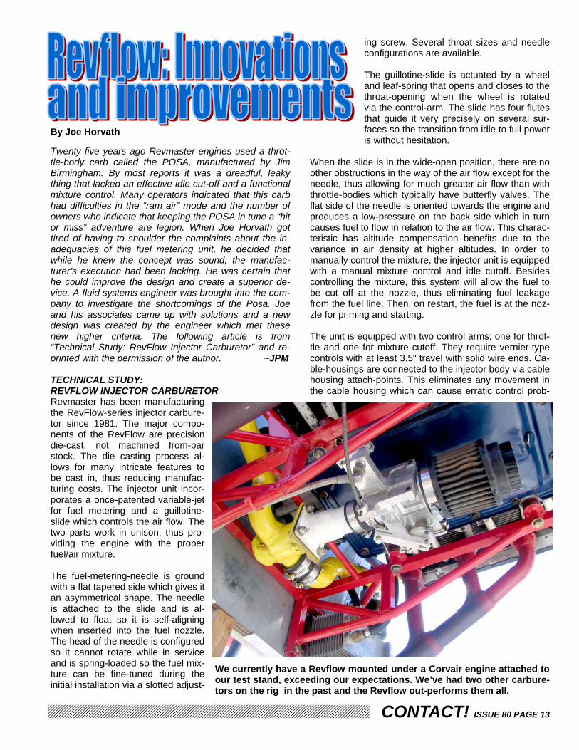
Twenty five years ago Revmaster engines used a throt-tle-body carb called the POSA, manufactured by Jim Birmingham. By most reports it was a dreadful, leaky thing that lacked an effective idle cut-off and a functional mixture control. Many operators indicated that this carb had difficulties in the “ram air” mode and the number of owners who indicate that keeping the POSA in tune a “hit or miss” adventure are legion. When Joe Horvath got tired of having to shoulder the complaints about the in-adequacies of this fuel metering unit, he decided that while he knew the concept was sound, the manufac-turer’s execution had been lacking. He was certain that he could improve the design and create a superior de-vice. A fluid systems engineer was brought into the com-pany to investigate the shortcomings of the Posa. Joe and his associates came up with solutions and a new design was created by the engineer which met these new higher criteria. The following article is from “Technical Study: RevFlow Injector Carburetor” and re-printed with the permission of the author. ~JPM TECHNICAL STUDY: REVFLOW INJECTOR CARBURETOR Revmaster has been manufacturing the RevFlow-series injector carbure-tor since 1981. The major compo-nents of the RevFlow are precision die-cast, not machined from-bar stock. The die casting process al-lows for many intricate features to be cast in, thus reducing manufac-turing costs. The injector unit incor-porates a once-patented variable-jet for fuel metering and a guillotine-slide which controls the air flow. The two parts work in unison, thus pro-viding the engine with the proper fuel/air mixture. The fuel-metering-needle is ground with a flat tapered side which gives it an asymmetrical shape. The needle is attached to the slide and is al-lowed to float so it is self-aligning when inserted into the fuel nozzle. The head of the needle is configured so it cannot rotate while in service and is spring-loaded so the fuel mix-ture can be fine-tuned during the initial installation via a slotted adjust-
ing screw. Several throat sizes and needle configurations are available. The guillotine-slide is actuated by a wheel and leaf-spring that opens and closes to the throat-opening when the wheel is rotated via the control-arm. The slide has four flutes that guide it very precisely on several sur-faces so the transition from idle to full power is without hesitation.
When the slide is in the wide-open position, there are no other obstructions in the way of the air flow except for the needle, thus allowing for much greater air flow than with throttle-bodies which typically have butterfly valves. The flat side of the needle is oriented towards the engine and produces a low-pressure on the back side which in turn causes fuel to flow in relation to the air flow. This charac-teristic has altitude compensation benefits due to the variance in air density at higher altitudes. In order to manually control the mixture, the injector unit is equipped with a manual mixture control and idle cutoff. Besides controlling the mixture, this system will allow the fuel to be cut off at the nozzle, thus eliminating fuel leakage from the fuel line. Then, on restart, the fuel is at the noz-zle for priming and starting. The unit is equipped with two control arms; one for throt-tle and one for mixture cutoff. They require vernier-type controls with at least 3.5" travel with solid wire ends. Ca-ble-housings are connected to the injector body via cable housing attach-points. This eliminates any movement in the cable housing which can cause erratic control prob-
We currently have a Revflow mounted under a Corvair engine attached to our test stand, exceeding our expectations. We’ve had two other carbure-tors on the rig in the past and the Revflow out-performs them all.
By Joe Horvath

CONTACT! ISSUE 80 PAGE 14
lems. The wire ends of the controls are secured at the control arms with barrel clamps. The unit is mounted to the intake system by a 1-1/2” hose and two clamps. Flanged adapters can be provided on request. (The one in the Corvair engine installation photo on the previous page shows an adapter I made to adapt the hose-clamp spigot of the Revflow to the AeroCarb flange that is welded to the intake manifold. ~Pat)
In the event multiple units are required, such as for in-line engine applications, up to 4 units can be ganged on a single throttle shaft. RevFlow-injector sizes range from 28mm through, 30, 32, 34, 36, 38, 40, 42, to 44mm. An alternate-air-source assembly is recommended for most single unit installa-tions. This assembly consists of an air filter, open on both ends, mounted onto the air-horn of the injector and held on with a clamp. The ram-air tube is clamped onto the opposite end. (The ram-air tube was omitted for our Corvair application pictured to the left~ Pat) The tube incorporates a valve that controls the ram air. When in the closed position the ram air is cut off and the engine is digesting warm filtered cowled air. The RevFlow injector is a 1-to-2 psi low-pressure injec-tor. It will function well on gravity feed, although some applications require a fuel pump. When a fuel pump is installed, the fuel pressure should be maintained at a nominal 1.5 psi. This is best accomplished with a fuel-return-line to the source. The return line can be restricted to achieve the 1.5 psi. For VW engine applications, Revmaster manufactures a special oil pump/fuel pump/oil filter assembly. This allows for an engine-driven fuel pump to be incorporated into certain applications. The RevFlow injector unit is floatless, therefore, it lends
itself to any mounting posi-tion; horizontal, vertical, etc. The RevFlow injectors have been installed in various types of experimental air-craft over the years, with excellent service history. The unit is not type certifi-cated (STC’d) and no such claims have been made, intentionally or otherwise. The original POSA carbs are still occasionally en-countered; most are being used as doorstops or paper-weights, it seems. I have never encountered another piece of aircraft hardware which is held in such vitriolic disrepute. There have been several other similar de-vices which have made it to the marketplace, including the RevFlow and the Aero Carb, which have fared far better in the court of public opinion. ~JPM
Revmaster has a hoard of Revflow carbs in stock. This batch of bodies is only a small part of the stock we saw at the factory. 28mm up to 42mm throat di-ameters are available. It seems entirely plausible that this selection would be good for 1/2 VW all the way up to 180 hp, irrespective of the engine manufac-turer. Since the carb can be mounted in just about any orientation, it seems well suited for experimental aviation.
The above photo is of an experimental version of the Revflow we found on Joe’s desk, the day we conducted our interview. This unit has been fitted with an elec-tronic fuel injection nozzle and a throttle position sensor. When mated with an oxygen sensor in the exhaust system and an ECU, optimal mixture can be estab-lished automatically. The real beauty of this system is that in the event of a com-puter malfunction or other electrical issues, if the carb is plumbed to gravity feed (in addition to the high-pressure needed by the injector) opening the fuel feed line to the carb will get the engine running again. This carb can also be fitted to most any multi-port fuel injection system, functioning as the throttle-body. If connected to gravity feed as described above, it too can act as a back-up for the MP-EFI system in the event of a failure.

CONTACT! ISSUE 80 PAGE 15
By Paul Lipps Here I am toolin' along in my fast Glaster behind that big ol' TIO-540, lookin' at those two multi-function displays. 280kts! 322mph! Hot damn! And I just came from the avionics shop where the avionics tech worked his magic on my pitot-static system while I fed numbers into the computer from my laptop, so I know what it says is true. Man! Could anything be better than this? After I get back on the ground my "master-of-skepticism" techie buddy gives me that raised-eyebrow look when I lay the num-bers on him. "What's wrong? Why are you giving me that fishy look? I asked. “I just got this thing calibrated to the n'th degree, so don't go givin' me that 'sumthin's wrong here' look. C'mon. Jump in this thing and I'll show you!" We zip on up to 7500' and level off. He asked me to slow to 90kts indicated. After a while of starin' at the panel, he made a note and tells me “to give it all she’s got”. He then asked me to put it on autopilot and altitude hold, then twirl the heading knob to keep us in a continuous turn. He made some notes, then after a little more than one turn, he told me to take up a certain heading. I pointed with unconcealed glee as the TAS numbers on the MFD slowly climb to 279kts! A few minutes and many scribbled notes later, he had me turn 180 degrees. More minutes and notes and he said to land. He then got on his cell phone and I heard him give my plane's registration number, and then ask for surface baro setting and forecast temperature and winds at 7500' in our area. He wrote those down, looked at his notes, entered some numbers on his circa 1979 HP41C pro-grammable, scientific calculator (told you he was a te-chie), pushed the buttons, then said "You're not going to like what I tell you. The first thing I had you do, slowing to 90kts IAS, was so I could see what your OAT said at that speed; it came within 1 degree of forecast. That's good! When we flew in a circle, with your autopilot keeping alti-tude constant, I watched your groundspeed and track on the GPS display, and noted the track associated with the highest and lowest speeds. That gave me the wind direc-tion and speed. Next I had you fly with the wind until groundspeed stabilized, then against the wind. During those two runs I wrote down IAS, GS, altitude, density altitude, OAT, TAS, and fuel flow. Averaging the ground-speeds from the runs in both directions gave me your true airspeed.” "So tell me, what was it?" I asked. "Well” he replied, “First, let me tell you what I found. As we went from 90kts to your top speed, your OAT in-creased 8ºC from 17ºC to 25ºC. This is what is called stagnation temperature rise. It is due to the impact, not friction, of the air molecules striking anything in their path, such as your temperature sensor. It is the same thing that heats up SR-71s and burns up meteors and
shuttles! This temperature error caused your computer to think your density altitude was 10,320' rather than 9410', a 910' error, which caused it to give a +1.4%. error in calculating your TAS. However, the location of your static ports appears to be where the actual pressure is 0.1" less than true static pressure. As a result, your indicated airspeed is 4.5kts high at 238.5kts, rather than 234kts.” "Alright, already!” I said, “All of that is great, but now will you please tell me, what do you think my true airspeed is?" "OK! OK!” he said, “ I won't keep you in the dark any longer! Your true air speed is 270kts, 311mph, which is still spectacular although a full 10kts lower that you thought!” "So! What can I do to fix this?" I asked. "Well, first, we need to move your temperature sensor into some shielded, stagnant location where it is out of the direct flow of air and the engine and cooling ex-haust.“ he said, “I have two sensors in my plane, one behind the rear spar and ahead of the flap, and the other inside, above, and in back of the elevator spar clear-ance-hole in the fuselage tail cone. They usually agree within 1°C and show no rise with increasing airspeed. Next, we'll put two or three layers of cellophane tape just behind the static ports. That will increase the pressure slightly. We only need 0.1". Then we'll go test these mods the same way we did on this flight. OK?" So now I have true airspeed. Actually, I liked what I had better! But I'll tell you this; when I go to sell the plane, guess what happens to the tape and temp. sensor?!? Stagnation temperature rise: Ts-TA =TA(k-1)(M)²/2 where: Ts, stagnation temperature, °R; TA, actual temperature, °R; °R=°F+459.7° k=specific heat ratio of air=1.405; M=Vs/V; Vs=49.04(°R)^½, ft./sec. V=true airspeed, TAS, appropriate units TR=temperature rise, °F Since Vs is a function of TA, the formula can be reduced and TA eliminated, leaving only the temperature differ-ence, which gives TR=(TAS)²/c. This gives "c" as: TR ft/sec mph kts ------------------------------------------------- °F 11,876 5521 4167 °C 21377 9938 7501 Paul Lipps [email protected]

CONTACT! ISSUE 80 PAGE 16
By Kuba Mysluk, Konstancin, Poland E-Mail: [email protected] Do you think that the FAA or other regulatory agencies throughout the world are difficult to deal with? Try build-ing and flying your own plane behind the Iron Curtain. This is how 39 year old Kuba began his aviation obses-sion. Now living in Konstancin, near Warsaw, Poland, Kuba has built 300+ hrs flying European “Microlights”, mainly powered by automobile and motorcycle conver-sions. From East Germany's Trabant (an atrocious little boxy 2-door automobile, featuring a two-cylinder two-stroke 600cc engine) to West Germany’s BMW pride. Kuba currently owns two planes: Czech's "Tulak" with his own 1800cc VW conversion installed and a motor-glider. But, (as Kuba puts it) “to stupid Polish regulations” all his flying has to be done in the nearby, aviation friendly Czech Republic. While living behind the Iron Curtain, Kuba broke the law by building a motor-glider. His first flights were also ille-gal, being flown from an illegal airfield. This could make for an interesting movie. Now that the wall is down, Kuba is free to build his own machines, using almost every engine available (except, as he puts it, “to expensive Rotaxes”). With no available technical support from the manufacturer, all design work is seat-of-the-pants and truly experimental. Considering liquefied petroleum gas (LPG)? He’s familiar with it. How about Diesel? That’s old news. Kuba is now embarking on refining the BMW motorcycle engine, more specifically the 1150cc version. English is certainly not Kuba’s native language but that’s how he submitted this article. I’ve done my best to tweak it for him with out losing his voice. I hope you enjoy read-ing this article as much as I enjoy bringing it to you. ~ Pat
Are you searching for a new 100 HP engine for your ex-perimental aircraft or future design? Then please read this article based on my personal experience with the BMW R1100RS motorcycle engine, as installed in the Zenair Zodiac CH601 UL. The particular plane I have experience with flew more than 1000 hours in 2003 with most of that flight time being logged as training flights at a local flight training school. Approximately 4,500 land-ings were logged, so in my estimation, this was a real test of the engine.
The above engine was displayed in the engine forum tent at Copperstate 2003. It’s the product of Art Lu-ther and he was kind enough to speak on the engine. Although this is not the same exact series of 1100cc BMW you are reading about, the redrive is the same.
The BMW engine, nestled in the cowl of a CH601 UL, sportin’ a light-weight WoodComp www.woodcomp.cz ground adjustable propeller.

CONTACT! ISSUE 80 PAGE 17
Please note that this article describes the negative ex-periences (problems) encountered, none of which would cause us to quit using this engine. Be assured that any and all future projects of ours will utilize this great BMW engine. One issue more: All the opinions expressed are my own; I don’t have any connection to “BMW”, or the engine’s conversion company “Take Off GmbH”, www.takeoff-ul.de or any other company or business invested with BMW. I do not guarantee your results will be as good as ours and always remember, this is not an aircraft engine. Please also keep in mind as you read this, we are not engineers nor professional aviation me-chanics. We are a bunch of enthusiasts and our testing is less than scientific. Please regard all these writings as those of an informed, experienced, amateurs.
BMW R1100RS This is a two cylinder, 1100cc "boxer", 4-stroke, fuel in-jected engine with a single electronic ignition system. Power is rated at 100 hp @ 7500 rpm. The alternator is rated at 600 W (40-50 amps), and there are several re-duction drives available: 2.46:1, 2.75:1, 3.05:1, 3.46:1. The weight is approximately 76 kg (168 pounds), dry, without the exhaust system The engine we flew was converted by "Take Off GmbH" of Germany and used a reduction drive with a ratio of 3.05:1. In my opinion, 2.75:1 would probably work best, but we are going to check 2.45:1 The engine is equipped with a type of centrifugal clutch (It's an odd sight to see the prop spinning from the wind with the engine off.) This clutch allows the engine to run more smoothly and can also save the crankshaft in the event of a prop strike. We love this feature because our students must make hun-dreds of simulated forced landings -this is really good thing if you mustn't turn engine off for this. COST A new, aero-converted engine with reduction drive can cost about 7500-8500 EURO (around $9-10,000 USD) Used engines can be secured and used as a starting
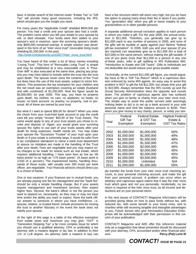
point. The cost of a low time engine (about 40,000km or about 25,000 miles) if purchased with out the computer and the injection system, can run as high as 1,500 EURO or $1,800 USD. 5,500 EURO ($6,500 USD) can get you a good used and very complete engine. The re-duction drive can set you back another 2,000 EURO ($2,500 USD). It all depends on the source, but you can find engines from a wrecked bike for the salvage price. PERFORMANCE The CH601 UL is typical all-metal Microlight. Due to its "school" function, the prop was set for best take-off and climb performance. With two persons on board, we saw a typical 5 meters per second vertical speed (1,000 FPM) and achieved 140km/h (70MPH) economy cruise. The fuel consumption at this setting is about 10-12 liters per hour (2.6-3.17 US gallons) of typical 95 octane auto-mobile fuel. Editor’s note: With a “standard” BSFC, 2.6 GPH works out to be around 38 horsepower. The flight parameters for a “cruise” prop depends on the propeller manufacturer. When we set to approximately 20º-21º @75% power, we saw a 170 km/h (105 MPH) cruise, and 220 km/h (135 MPH) as max horizontal top speed. Here are a few examples of typical engine speeds: Engine Idle, prop not spinning - 1,200RPM Centrifugal clutch engaged - 2,200 RPM Cruise - 4,800-5200 RPM Redline -7,200 RPM (depends on prop) MY OWN OPINION Excellent, brilliant engine, but at this time, the reduction drive leaves a bit to be desired. The reduction drive looks like it was designed for a pusher application. We are in the process of manufacturing our own redrive and it MAY be ready by the time you read this article. With a new clutch and redrive there were no problems for the first 400 hours with the plane doing 99% take-off and landing exercises (patterns or circuits if you prefer). The engine manual supplied by "Take Off GmbH” states that the clutch is good for 400 hours and at exactly 400 hours, we encountered vibrations just before the clutch broke. The vibration was minimal at idle (1,200 RPM) and between 3,000-3,500 RPM. We replaced the clutch but after the next 250 hours, problems begin again. We fixed it a few times with these same results; due to vibra-tions we had a broken flywheel. The flywheel is stamped steel, about 5 mm thick with a steel ring gear held in place with rivets. All damage was similar, just loose rivets. When we modified it to accept solid screws instead of rivets, the steel cracked. The boxers typically have a big and fast changes in a mo-ment of inertia (torque) which simply destroyed our fly-wheel. The solution was a 3.90 kg flywheel. The original was only 1.90 kg, too light-weight and weak in my opin-ion. Once installed, the new flywheel made the engine run a bit smoother and seemed to solve our problem; the
BMW 1100RS
Measured at the rear wheel
CONTACT! ISSUE 80 PAGE 18
vibration was gone. Looking at the engine as installed in the motorcycle, the flywheel is very heavy. We chose to emulate that and do away with the light-weight flywheel supplied with the PSRU. As a result of the vibrations, we also suffered a crack in the aluminum engine case. A little welding proved to be only a temporary cure, as the alloy has a silicon content, which we don’t have the technology to deal with properly. I think we had these cracks after first 400 hours. I’d like to say a bit about vibrations in other BMW1100s engines. We had numerous early BMW conversions in Poland but, due to vibrations, we had few unexpected engine failures. As a result of this the engine doesn’t have a good reputation here. We are confident that the true source of many of the problems encountered to date was brought about by the flywheel; it was just too weak. One of my other Czech friends has a CH701 with BMW1100 and he had forced landing. As he told me, it was just a huge vibration without reason, and as a result, the engine threw a prop blade. When we examined the engine we found a destroyed PSRU damper bushing. BACK TO OUR BMW One dumb problem was in the alternator. The original German design has a generator fan which works "opposite" to the airflow. Due this bad design, we have to change the alternator drive belt every 60 hours! The al-ternator belt was destroyed a few times by the elevated temperature of the alternator pulley. The pulley was just too hot and when the engine was not running, the belt’s rubber was damaged. We fixed the fan, of course, at the same time we fixed the flywheel situation. During the following 300 hours we never suffered a single belt breakage. We’re not certain, but potentially the vibrations were as harmful to the belt as the hot pulley. We did not have any problems with the basic engine, just the PSRU. Cylinders, crank, bearings, valves, pistons and rings were all within specification after 1,000 hours. No problems with the fuel injection or electronic ignition. We had zero unexpected engine stops! The engine starts right up without any problems, hot or cold. INDUCTION AND ATTENTION TO DETAIL One of the many things I like about this engine is the electronic fuel injection. One reason for this is that the system (like most fuel injection systems) is not as sus-ceptible to induction icing as a standard carburetor is. There’s no reason to fear the complications of the com-puter either, as any BMW bike serviceman can help you with any of the engine settings. The most difficult part to get set up properly is with throttle synchronization. You need to be very careful when tuning the throttle bodies and injectors; using a good flow indicator as guessing just won’t cut it here. Next issue: Spark plugs. They must be within specifica-tion. This engine does not like "hotter" or "colder" plugs.
Another area to pay close attention to is that the Lambda sensor (O2 sensor) must be torqued in place exactly as specified. Strange, but the BMW engines didn’t work smoothly when it was a little bit under torqued. Careful attention must be paid to the electrical wiring. This engine will stop if there are any interruptions in the system. We had situation where a mechanic replaced the battery. By mistake, he didn’t secure the connections tight and correctly. As a result, the engine didn’t run smoothly due to cable vibrations on connector. In our next CH 601 we will have a small dedicated back-up bat-tery for computer unit. Still another tip: in this engine you must have about 5 liters of volume between injection unit and the air filter. The huge stock composite tubes, running from the air-filter to the throttle-body, will become useful here.
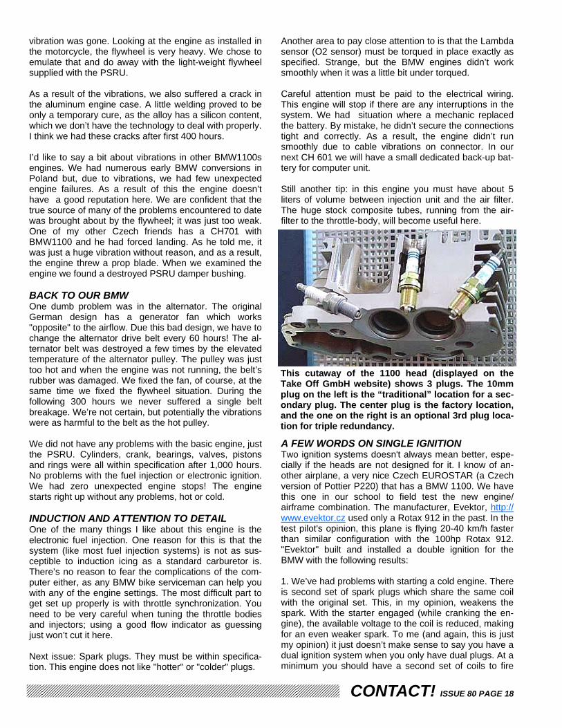
A FEW WORDS ON SINGLE IGNITION Two ignition systems doesn't always mean better, espe-cially if the heads are not designed for it. I know of an-other airplane, a very nice Czech EUROSTAR (a Czech version of Pottier P220) that has a BMW 1100. We have this one in our school to field test the new engine/airframe combination. The manufacturer, Evektor, http://www.evektor.cz used only a Rotax 912 in the past. In the test pilot's opinion, this plane is flying 20-40 km/h faster than similar configuration with the 100hp Rotax 912. "Evektor" built and installed a double ignition for the BMW with the following results: 1. We’ve had problems with starting a cold engine. There is second set of spark plugs which share the same coil with the original set. This, in my opinion, weakens the spark. With the starter engaged (while cranking the en-gine), the available voltage to the coil is reduced, making for an even weaker spark. To me (and again, this is just my opinion) it just doesn’t make sense to say you have a dual ignition system when you only have dual plugs. At a minimum you should have a second set of coils to fire
This cutaway of the 1100 head (displayed on the Take Off GmbH website) shows 3 plugs. The 10mm plug on the left is the “traditional” location for a sec-ondary plug. The center plug is the factory location, and the one on the right is an optional 3rd plug loca-tion for triple redundancy.

CONTACT! ISSUE 80 PAGE 19
the second set of plugs if you want closer to a “true” dual (redundant) system. 2. The sparkplugs are small 10mm, and the second was installed on the “side” of combustion chamber (see the “peanut plug”, photo on the previous page). As a result, we had two "flame fronts” colliding as the fuel ignited. Usually they would meet each other in an incorrect place and the result would be a burnt or “holed” piston. We had a forced landing on the EUROSTAR due this fact.
ENGINE MAINTENANCE After the first 10 hours: Change the oil and filter. Check the valve lash Every 100 hours: Change the oil and filter, sparkplugs and check valve lash. The valves are hydrau-lic, but check them anyhow. Every 400 hours: Change shock absorbers (neoprene bushings), damper and clutch. 500-800 hours: Basic examination. That's end for now. If anyone is interested any added details more - I'm still present on Yahoo AirVW group or please ask me directly at [email protected] Kuba Mysluk
Do you think BMW only ever made fine sports cars and high-end motorcycles? Here’s some history and background on BMW: Bayerische Motoren Werke AG (BMW), Ger-man manufacturer of automobiles, motorcy-cles and aircraft en-gines. Based in Munich, Germany, the company is the leading auto ex-porter in Europe. The English translation of the company's name is Bavarian Motor Works. The company traces its origins to 1913, when a Bavarian named Karl Rapp began an aircraft-engine shop in Munich named Rapp Motoren Werke. In 1917 Rapp resigned and the company, led by Austrian engineer Franz-Josef Popp, changed its name to Bayerische Motoren Werke. That same year chief engineer Max Friz designed the company's first aircraft engine, the six-cylinder Type IIIa, which created strong demand for BMW engines. When the 1919 Treaty of Versailles prohibited German companies from producing aircraft and aircraft engines, BMW switched to making air brakes for railway cars. In 1923 Friz developed the com-pany's first motorcycle, the R32, a model that held world speed records for motorcycles during most of the 1930s. In 1928 the company entered the automobile business by acquiring Fahrzeugwerke Eisenach (Eisenach Vehicle Fac-tory), a maker of small cars based in Eisenach, Germany. In the 1930s BMW began producing a line of larger touring cars and sports cars, introducing its highly successful model-the 328 sports car-in 1936. After World War II ended in 1945, Allied forces dismantled the company's main factories. BMW made kitchen and gar-den equipment before introducing a new, inexpensive motor-cycle to the German market in 1948. The company's return to auto production in the 1950s resulted in poor sales. In the 1960s the company turned its fortunes around by focusing on sports sedans and compact touring cars, and it began to compete with Mercedes-Benz in the luxury-car markets of Europe and the United States. BMW's U.S. sales peaked in 1986 but then dropped steeply, partly due to competition from two new luxury cars-Lexus, made by Toyota Motor Cor-poration, and Infiniti, made by Nissan Motor Co., Ltd. The 1989 collapse of the Berlin Wall led to a boom in car sales in Europe, and in 1992 BMW outsold Mercedes-Benz in Europe for the first time. In 1990 BMW formed a joint venture with the British aero-space company Rolls-Royce PLC to produce aircraft engines for business jets. In 1992 BMW broke ground for a major automobile plant in Spartanburg, South Carolina, its first automobile plant in the United States. In 1994 BMW acquired 80 percent of the Rover Group-a British manufacturer of small cars, luxury cars, and Land Rover sport-utility vehicles-from British Aerospace PLC. The $1.2 billion acquisition brought the company into new markets.
Stroke 4
Displacement 1085.00 CC (66.21 cubic inches)
Power 90.00 HP (65.7 kW) @ 7250 RPM
Torque 95.00 Nm (9.7 kgf-m or 70.1 ft-lb) @ 5500 RPM
Bore x stroke 99.0 x 70.5 mm (3.9 x 2.8 inches)
Valves per cylinder
Intake / Outlet dia 34mm / 29mm
Cooling system Air
Compression Ratio 10.7:1
Valve control OHV, using chain drive, cup tap-pets, push rod and rocker arm
Induction system Electronic injection, Bosch Motronic MA 2.2
Engine lubrication Wet sump
Ignition Electronic ignition; Bosch Motronic MA 2.2
Starter Electric, 1.1 kw
Spark plugs Bosch FR6 DTC
4
Engine specifications Model BMW R1100RS
Year 1993-2001
Engine type Two cylinder boxer
The inspiration for the BMW Roundel came from BMW's aircraft legacy.

CONTACT! ISSUE 80 PAGE 20
By Percy (Pat) Lorie III CONTACT! MAGAZINE and its parent 501(c)(3) charity, Aero-nautics Aviation Enterprises, (like all educational charities) needs and welcomes your support and contributions None of us likes having to face the simple truth that as soon as we are born, we live on a time-line that is not infinite. Because so few wish to face the reality of death, most die without plans or, in fact, a will or trust. However, this is not entirely true, as if you do not make plans for your hard-earned monies and other property, both real and personal, upon your death, the state in which you live will decide just what will become of your life’s work. All who die “Intestate” (without a will) end up with a will, but the government, NOT YOU, will be the one to write it. I apologize again to our non-USA subscribers, since the actual laws and articles specified in this writing are applicable only within the USA. Hopefully you can get some help from this arti-cle anyway. For those of you already convinced that some action is needed I just came across a very good software program which in-cludes documents complete with AUDIO EXPLANATIONS. “Will & Trust Kit” by Suze Orman may be ordered from her web site ( www.suzeorman.com ). I found it at COSTCO for $12.49. If you already have these documents in place it is still a good idea to buy and listen once again before you might give it to a friend or relative. I do not recommend this program as a substi-tution for, but in addition to, an attorney. There are a lot of figures thrown about but in general it is ac-cepted that you are five times more likely to become disabled than to die in any given year. Disability will be discussed in a later article but accept the fact that the USA Social Security disability is very difficult to obtain and most employers’ disabil-ity payments and benefits continue only for limited, relatively short periods. If you have not started pilot training or have not flown in many years it may be substantially easier to obtain needed “Disability Income” or “Life Insurance” before you add aviation as an avocation. If you are self-employed look into “Disability Extra Expense” coverage to protect your business. Let’s take a short look at the USA estate tax laws in brief and how they may affect you. Remember that in addition to this tax you may have to pay probate including attorney’s fees, local state taxes and charges by your CPA for preparation of the estate tax return. The average fee charged by a CPA is at least 1% of the value of the estate. Sounds high, but a good deal of the charge goes to pay for their “errors and omissions” insur-ance coverage. Yes, with “inter vivos” (“living” as opposed to “testamentary” set out in your will) trusts probate may be avoided or reduced to almost nothing. However, in many states it is advisable to file probate even on a zero estate to start the “Statute of Limitations” running for liabilities or debts that may have been incurred by the deceased. An additional advantage of an inter vivos trust combined with a “pour-over will” (A will that transfers non-trust assets to the Trust upon death) is the speed with which the estate may be distributed and closed, normally less than one year rather than a long indeterminate period.
One comment which often comes is, “I have very little” or “I have placed my children on our cars, home, safe deposit box and bank accounts.” This is the worst way to handle your es-tate! One by one let’s take a brief look at some of the problems this can create. First, any transfer (and adding their name to your accounts is a transfer) is considered a GIFT and under the current law if more than $11,000 is gifted in 2005, you must file a “Gift Tax return”. By “gifting” an automobile (and keeping your name on the title) you have placed your entire net worth in the owner/driver’s hands. When (not if) an accident occurs, you could potentially lose everything you have worked to accumu-late. Some states do provide for designation of a beneficiary owner on auto titles and this does avoid the liability problem. Many of us wish to stay in our homes as long as we possibly can but with your children as co-owners there is a conflict of interest that could rear its ugly head. You may have absolute confidence in your children, great, but what if they become disabled or die intestate which would automatically transfer co-ownership of your home to their spouse or children? Then there is always the possibility they could divorce. The bank account has essentially the same problems as the car (gift tax concerns) and home, except it is easily attached for their per-sonal debts. Then there is “stuffing” your safe deposit box with cash or valuables. This idea is not new. Your government has dealt with this situation before. On the “Estate Tax Return” is a simple question asking if you own or have access to any safe deposit box. Most states will seal the box upon death and it must be opened and inventoried with officials present after death. Dual name on a safe deposit box just won’t work within the estate tax laws. Just when does Uncle Sam get into my loved-one’s pockets? There is NO federal tax due if your spouse is the beneficiary of your estate. BUT, what happens when the spouse dies? In the year 2005, your estate tax exemption shields only $1,500,000.00. to a non spouse, i.e. your children or others. This amount increases over the next few years to become an unlimited amount in year 2010, BUT the law “sunsets” in 2011. The reality is you must plan for the law to be changed and I am forecasting that the exemption will revert to $3,000,000. Both amounts sound large but those with 401K retirement plans, farms, appreciated real estate, and personal businesses may find this amount to be low. (I know at least one of you must have purchased a P-51 new for $500, which is now worth in excess of $1,500,000.) In addition “Life Insurance” may add to your total estate. Your agent may have told you it is “not tax-able” but if you are the policy owner and/or pay the premiums it is in fact part of your taxable estate. Why is the USA Government changing the estate tax exemp-tion limits? The theory was to protect the family farm and the family business. Often both had to be sold to raise money to pay estate taxes. At the old exemption, shielding only $600,000 and quickly becoming an effective federal tax rate of 58% of the value of the estate over this exemption, many non-spouses were paying total estate costs of about 62% . As of today, the situation of estate taxes is much improved but in the future you should expect the law to change and change still again. These constant changes make planning very hard for us all and I strongly suggest that diversification of methods of avoidance of unnecessary tax payment takes serious thought. You will take some actions which do not work out and, in fact, may cause you additional tax. But if many methods of control are used, you may expect an overall savings. By looking at what has worked and not worked in the past, along with changes the USA Government has made in the past, you will develop some insight into future changes to anticipate in the USA estate tax
Part II
CONTACT! ISSUE 80 PAGE 21
laws. A simple search of the Internet under “Estate Tax” or “Gift Tax” will provide many good resources, including the IRS, which should give you the insight you need. For many years the “Applicable Credit” shielded $600,000 per person. You had a credit and your spouse also had a credit. The problem came when you left your estate to your spouse by will, or died intestate. Your funds were then added to your spouse’s and in essence, upon the surviving spouse’s death, only $600,000 remained exempt. A simple solution was devel-oped in the form of an “inter vivos trust” (revocable living trust) shielding $1,200,000. in the past. http://www.investorwords.com/2577/inter_vivos_trust.html You have heard of this under a lot of fancy names including “Loving Trust”. This form of “Revocable Living Trust” is simple and may be established at a very reasonable cost. A “Pour-Over Will” is also executed at the same time, placing any prop-erty you may have failed to include within the trust into the trust upon death. The spouse never owns the contents of the Trust but does have the use of the trust assets, subject to minor limi-tations. This preserves the tax exemption for your children and the net result was an exemption covering an estate (husband and wife combined) of $1,200,000. Now the figure would be $3,000,000. for year 2005. This way, you have no property upon death. No clothes; no cars; no airplanes; no boats; no house; no bank account; no jewelry; no property, real or per-sonal. All of these are owned by your trust. But what if I want to spend $50.00 for dinner? When you write the check from your trust-held bank account to pay the credit card bill you simply “revoke” $50.00 of the Trust Assets. The same would apply to any of your trust assets you chose to re-voke and dispose of. Again, you would grant your surviving spouse the rights to use part of your trusts assets after your death for living expenses, health needs etc. You may make your spouse the “Successor Trustee” of your trust upon your death or if your estate is extremely large, it would be safer from a tax compliance standpoint to name a bank trust department to assure no mistakes are made in the handling of the Trust after your death. Fees are negotiable and you may expect ex-tra charges to be made for assets such as real estate, which requires additional handling. I have seen fees as low as “45 basis points” to as high as “175 basis points”. (A basis point is 1/100 of a percent.) The experienced banks, handling thou-sands of these trusts, with usually over 200 trusts per bank officer, are negotiable. Your financial advisors should direct you to a choice of banks. One or two cautions: If your finances are in mutual funds, you are already paying one fee for management and the “bank fee” should be only a simple handling charge. But if your assets require management and investment services, then expect higher fees. Second, the bank’s officer is not the person you want to depend on, necessarily, as they may or may not have time and/or the ability you want or expect. Have the bank offi-cer answer to someone in whom you have confidence. i.e. spouse, relative, or trusted friend. Include provisions for moving the trust to another fiduciary in the event the bank does not satisfy your spouse. At the right of this page is a table of the effective exemption from estate taxes and maximum you may give. “GST” is “Generation Skipping Tax” a far more complex issue for which you should use a qualified attorney, CPA or preferably a tax attorney with a masters degree in tax law, in addition to their J.D. or LLB degree. An attorney (with a masters in tax) can
have a fee structure which will seem very high, but you do have the option to paying many times their fee in taxes if you prefer. You “generation skip” when you gift or leave estates to your grandchildren or in other parallel persons. A separate additional annual exclusion applies to each person to whom you make a gift. For the year 2005, the annual exclu-sion is $11,000. Therefore, you generally can give up to $11,000 each to any number of persons in 2005, and none of the gifts will be taxable or apply against your lifetime “federal gift-tax exemption”. In 2005, both you and your spouse (if you are married) can separately give up to $11,000 (for a total of $22,000) to the same person, without making the gift taxable. If one of you gives more than $11,000 to a person in any one of these years, refer to gift splitting in IRS Publication 950, “Introduction to Estate and Gift Taxes”. Gifts to individuals are not deductible but would reduce your gross taxable estate. Technically, at the current $11,000 gift figure, you would argua-bly have to file a “Gift Tax Return” which is a capricious deci-sion enforced by some IRS agents. An easy way to avoid this problem is NOT to gift the full $11,000. but simply limit your gift to $10,990. Always remember that the IRS rounds up and the Social Security Administration does the opposite and rounds down. The problem of capricious agents also has surfaced when you give to family or charity from your inter vivos trust. The simple way to avoid this public servant (with seemingly nothing better to do) is to set up a bank account in your sole personal name and limit the balance amount to $100. Then when you give money to any charity, person, or entity you sim-
ply transfer the funds from your inter vivos trust checking ac-count, to your personal checking account, and make the gift from your personal account. A problem can occur when an arbitrary and capricious agent claims that it was the inter vivos trust which gave and not you personally. Incidentally, no tax return is required of the inter vivos trust, as all income and de-ductions are on your personal return. In the next issues of CONTACT! Magazine information will be provided giving ideas on how to pass funds without tax, with reduced tax, with some benefit to your loved ones, and to charities while still receiving tangible and intangible advantages to you. Future donors who give Aeronautics Education Enter-prises will be acknowledged with their permission in this col-umn of your publication. CONTACT! Magazine and AEE offer this reference material only as a suggestion that ideas presented should be discussed with your attorney, CPA, accountant and/or other financial advi-sors. Percy (Pat) Lorie III
Year
Federal Gift Tax
Exemption
Federal Estate & GST Tax Exemption
Highest Federal
Estate & GST Tax Rates
2002 2003 2004 2005 2006 2007 2008 2009 2010 2011
$1,000,000 $1,000,000 $1,000,000 $1,000,000 $1,000,000 $1,000,000 $1,000,000 $1,000,000 $1,000,000 $1,000,000
$1,000,000 $1,000,000 $1,500,000 $1,500,000 $2,000,000 $2,000,000 $2,000,000 $3,500,000 Unlimited
$1,000,000
50% 49% 48% 47% 46% 45% 45% 45% N/A 55%

CONTACT! ISSUE 80 PAGE 22
relied on the kindness of volunteers to allow me time to get refreshed and maybe take in a little of the show. This year, the illustrious John Moyle of CONTACT! Magazine writing fame, accompanied me to the event, and allowed me enough time away from the booth to really see what it’s like to be in attendance from the other side of the sales table, and it was great! Although I’m not exactly new to aviation (I started flying gliders in 1976, and have been an EAA member since 1996), I am new to the larger fly-in circuit. I have an un-natural aversion to large crowds (this tends to keep me away from music concerts, the county fair, amusement parks, and even Wal-Mart for that matter) and I’m more of the type of person who likes to be in there, actually doing, rather than watching. And besides, if you’ve seen one red Pitts doing endless spins, with the monotonous, ear-splitting drone of the prop tips going supersonic in the dive, while trailing white smoke, you’ve seen and heard them all. My previous take on the larger venues such as SnF or OSH was that of a large convention where I was one of tens of thousands of nameless “attendees” (or walking wallets if you prefer) who were there to just “look but don’t touch” as is posted on so many prop-cards. But this year I discovered the workshops! A place where I could learn by doing, getting one-on-one tutelage from an expert, and with my own hands, actually make a part! I’ve always been intrigued with shaping flat metal into com-pound curves, but I’ve never possessed the skills or knowledge required, so I wandered into the sheet metal fabrication tent. Roughly 45 minutes later I exited the tent with an expertly crafted part in my hands and a hands-on working knowledge, great enough to feel confident to head home to my shop and start making airworthy parts. But the workshops don’t begin and end with sheet metal fabrication. There were tents filled with experts to teach me hands-on how to cover a surface with fabric; how to hot-wire foam and glass over it; how to make a wooden wing rib; how to tig-weld; how to do just about any new skill I might need to complete or even start a project. So if you are like I was, and have ever considered that the bigger fly-ins don’t really have anything to offer you except high-priced food and vendor tents filled with people selling ladders, pots and pans, as well as other non-aviation re-lated material, (not to mention the toys that are so outra-geously priced we could not afford to use them if we bought them) then I urge you to give it another look. Check out the workshops and make something. CORRECTION I would like to offer my most humble apology to Tom Aberle for the gross spelling error in the title of his article in the last issue. When I create the titles for each article, the font we use is not spell checked, as the program sees it as a graphic not a word. I know how to spell Tom’s last name, but I made a typo that the spell checker didn’t pick up on. So for the record, Tom’s last name is Aberle (with a B), not Amerle (with an M).
FAST FORWARD TO THE PRESENT I wish to seriously apologize to all our readers and sub-scribers, concerning the lateness of this issue. I also wish to thank each of you for your patience with this matter. Many of you already know that this is not a full-time en-deavor for any of us associated with CONTACT! Maga-zine, and of course, this is an unpaid, 100% volunteer effort. That being said, the magazine business is con-ducted out of my personal office. I own and operate a drafting business where we do residential design full time. Earlier this year we lost the lease of the building in which we have been conducting business for over seven years. This was totally unexpected and pretty much had me fac-ing the demise of my livelihood. Needless to say, from that point forward, any and all “spare” time had me scram-bling to find new digs for both businesses. I already knew that our town had a serious shortage of suitable (affordable) office space for lease or rent, so even though we didn't limit our search to just purchasing property, this became our primary goal. Long story short, we found a run-down building that could be converted to fit our needs, that was in a suitable loca-tion, and the price was right. After a short escrow, John Moyle and I spent the next two months at the new prop-erty, demolishing pretty much the majority of the building. We removed all the exterior and interior wall finish and material, installed all new doors and energy efficient win-dows, moved a few walls (doors and windows) around, and turned a lump of coal into a sparkling diamond. So now, CONTACT! Magazine and Construction Designs have a new home, and I’ve recovered enough from the move to FINALLY get this issue to print. In the meantime, the next issue (#81) is coming together nicely and we hope to get it out on the heels of this issue, so expect to see it in your mailbox soon. If you’d like to see the con-struction progress, visit www.Construction-Designs.com CONTENT We have not been intentionally leaving out the larger dis-placement/horsepower engine articles from our recent publications, we just don’t have any to publish. We could use a little help from you. If you have a project of interest, please let me know. We can certainly help you with the article (if you feel the need) as we did Kuba in this issue. If you know of any interesting planes you’d like to read about, let me know that as well. As much contact informa-tion as you can put together would also be beneficial. A SPECIAL THANKS I would like to give a special thank you to Bruce Sturgill, the producer of Sport Pilot TV, www.sportpilottv.com for the graphic assistance he gave me with the Revmaster photo on page 3. Bruce used his talent and skill to neatly crop out all the background, as well as the supporting structure, in the photo supplied by Revmaster. Bruce is on board to help with this type of art in the future.
SWITCH ON! Continued from page 2
See ya at the Copperstate workshops! Patrick Panzera

CONTACT! ISSUE 80 PAGE 23
By John P. Moyle Photos by Patrick Panzera John O. Thompson has led an inter-esting life centered in an aviation based career path. At a very early age he was hanging around the air-fields in eastern Missouri hoping to score a ride. He chose to enlist in the U.S. Army Air Corps in 1947 and served as a flight crew member on-board C-47’s before and during the Korean war. Later on, he several on-board B-25’s.
Upon his release from active military duty he re-turned to the St. Louis area and began working on aircraft in the civilian arena. He and a partner took over the aircraft maintenance facility at a small county airport and were fortunate enough to garner some special project work from nearby aviation giant McDonnell Aircraft. These development contracts allowed the business to flourish, but more impor-tantly, exposed John Thompson to the corporation. His talents were apparently well appreciated, be-cause from these humble beginnings came a lifetime career. He traveled the globe as a customer relations manager, finally retiring after 38 years with McDon-nell-Douglas. His last duty assignment, as the F-18 West Coast Customer Service Manager at Lemoore Naval Air Station, Lemoore, CA, is how the CON-TACT! Magazine staff had the good fortune to be-come his neighbor in adjacent hangars at Hanford Municipal Airport in California’s central valley. Le-moore and Hanford are neighboring cities.
Retirement has given John the time to pursue (and fulfill) his dream of building and flying his own aircraft. John investigated many popular designs and was interested in an airframe which would allow an automotive engine conversion to be installed without too much difficulty. He and a friend visited a builder whose Kitfox IV 1200 pro-ject never proceeded very far along the way towards completion, but when John’s friend decided not to pursue the purchase of this otherwise neglected project, he de-cided to make an offer himself! The deal was struck and the components were relocated to a communal hangar in Hanford. The purchase consisted of only the welded steel fuselage structure, the cub-style bungee sprung landing gear, plus the wing and empennage pieces. Kit construction proceeded following the manufacturer’s in-struction until John got to the engine installation.
THE ENGINE His preferred powerplant was a horizontally-opposed water-cooled Subaru engine, the style which has be-come a favorite among experimental aircraft builders. John chose an EA-81, which is not a model installed in Subaru automobiles sold in the USA, but which does arrive here after being previously operated in Asian countries. This particular engine was purchased from a local engine importer as a used engine and was adapted by John for use in his Kitfox while it was still under con-struction. This plane has never flown with any other type engine installed. Thompson had no desire to tempt the fates with even the finest two-stroke technology that the fac-tory recommends. Fortunately there are a lot of Subaru engines, in a wide variety of displacements and perform-ance, readily available to the experimental aviation com-munity. There have been so many Subaru conversions installed in experimental aircraft that it’s hardly consid-ered “groundbreaking” any more, although in truth, each conversion is unique in some way. Most importantly, sev-eral commercial entities offer propeller speed reduction units (PSRU) for the Subaru, so that part of the equation is merely a matter of selecting a suitable unit. In this case, John feels he made a mistake in matching this PRSU with his application. PSRU John chose the RFI-brand PSRU which Don Parham used to build in Oklahoma, but this particular model was intended for Gyrocraft where the engine is typically in-stalled in a pusher configuration. John found it very “tricky” to get the 80mm Gates-type cog-belt to track cor-rectly with his tractor installation. He was eventually able to sort out the issues but categorically states, that for this particular application, he would not recommend this re-drive installation to others. The PSRU features a ratio of

CONTACT! ISSUE 80 PAGE 24
2.1: 1 which gives the 72” diameter, three-blade Warp Drive prop the ideal speed of 2,380 RPM when the Su-baru is making its best torque around 5,000 rpm.
ENGINE MOUNT John selected a motor mount manufactured by Western Power of Bakersfield, California. The mount was in-tended for this model of aircraft, but it had to be modified to facilitate the Subaru installation in the Kitfox, which was accomplished with relative ease. (The Bakersfield company no longer offers this product.) COOLING SYSTEM One of the unique challenges of adapting a water-cooled engine to an airframe is choosing the correct radiator size and location; both of these items being critical to the success of the installation. The science involved in arriv-ing at the correct dimensions sometimes results in a ra-diator so large as to render it impossible to mount unob-trusively. It’s also possible to end up with a compact unit which works fine on the ground, yet fails to provide ade-
quate cooling capacity for the treacherous climb-out phase of flight on a hot summer day. John’s solution in-cludes a 7” x 24” x 3-row brass radiator. John mounted his radiator (seen in the above photo) to the belly of the airplane just aft of the firewall in a fiberglass fairing. At first he found that the system worked well enough on the ground, but did not provide adequate cooling in full power mode. Mathematically the volume of the coolant and the dimensions of the radiator were correct, so the problem was thought to be the same as what the World War II engineers discovered when they dealt with similar problems in the water-cooled fighter aircraft of the era; it seems the air entering the radiator must be slowed.
So against conventional thinking, the entry orifice was restricted in progressive steps until the amount of cooling air was just enough to provide sufficient volume while allowing the air in the plenum to expand (slowing it down) which gives the air molecules sufficient time to extract the heat while passing through the radiator fins. The standard Subaru water pump is employed and per-forms its function more than adequately. A firewall- mounted expansion tank completes the cooling system.
Among many other details in this photo, one can see the creative geometry applied to the engine mount.
The compact yet effective radiator is located just aft of (and below) the firewall, and neatly cowled. The exhaust stacks had to be lengthened to keep the ex-haust heat from adversely affecting the cooling abil-ity of the radiator.
The PRSU used was designed and built for a pusher application and gave John some problems. There-fore he does not recommend it for this application.

CONTACT! ISSUE 80 PAGE 25
INDUCTION SYSTEM The intake system is a modified Subaru aluminum mani-fold with an Ellison throttle-body fuel injector. This guillo-tine slide style carburetor has found wide acceptance in a large and diverse group of engines used in experimen-tal aircraft. The smallest unit, the EFS-2, intended for engines up to 85hp, is no longer marketed but is still ac-tively supported by Ellison Fluid Systems, the manufac-turer. The EFS-3A is designed for engines from 85hp to 140hp. The model used on our subject engine is an EFS-2 and does not have carb heat in the traditional, manu-ally-applied hot air, fashion, but rather the intake mani-fold has hot water pumped past the base flange of the throttle-body. Once normal water temperatures are reached there seems to be little chance of ice forming with this system. John Thompson’s experiences to date, which includes hundreds of hours flying this component combination, has certainly proven to be trouble-free in that respect. However he does believe that his engine would benefit from the next larger size Ellison. EMPENNAGE One effect felt from the Subaru installation is that the standard vertical tail area is insufficient to cope with the additional torque supplied by the PSRU-equipped en-gine. While these devices do not improve horse power output (at a given RPM), they are torque multipliers and
the tail of this aircraft was never intended to deal with the amount now being applied. These planes were originally designed for a Rotax 582 of only 65 hp. A trip to Nampa, Idaho, offered John the opportunity to discuss the inade-quate longitudinal stability with the factory engineering staff. He discovered that they were completely aware of this deficiency, and had increased the tail height by seven inches to compensate. Unfortunately, this modifi-cation began with serial #1717 and John’s airframe is #1714. Just missed! The choices then ranged from add-ing vertical tips at the ends of the horizontal stabilizer to adding height to the factory tail and rudder assembly. Eventually an engineer suggested that just adding some volume to the vertical surface by extending the leading edge several inches might do the trick. This was at-tempted, and found to be just the ticket, and had the ad-vantage of being by far the simplest modification of those considered. As a trial-and-error method, John bent up a five inch leading edge for the vertical stabilizer and attached it with aluminum tape. This approximated the additional tail area offered by the factory’s modification and proved to be perfect. A permanent corrective part was constructed and rigidly attached. Only a close inspection would even catch your attention, since this alteration looks com-pletely natural on the Thompson Kitfox.
WING SPAN While John had the attention of the staff engineers at SkyStar, an inquiry was made concerning the possibility of reducing the wingspan. John had always felt that the wing loading was too low for his intended mission of daily flights at relatively low altitude in central California’s San
In the above photo, we can clearly see that several inches of aluminum have been added to the leading edge of the vertical stabilizer, increasing its total area. This change corrected the longitudinal stability problems John was suffering with the original tail.

CONTACT! ISSUE 80 PAGE 26
Joaquin Valley. This area is well known for its bumpy air in warm weather. The farmland kicks up major thermals and light aircraft tend to get knocked around rather vigor-ously. He was told that he could shorten each wing by one bay, or about eighteen inches per side. The resultant three feet of reduced wingspan has provided just the right amount of additional wing loading and has trans-formed this Kitfox into a more comfortable machine.
ELECTRICAL SYSTEM AND INSTRUMENTS The electrical wiring is all routed to a service buss inside the cabin, between the firewall and the panel. It’s a uniquely tidy installation, and quite compact. The instru-ment panel itself is fairly typical of most Kitfox brand air-craft, with all the basic flight instruments for cross-country flight plus all the necessary instruments to moni-tor the condition of an experimental water-cooled engine.
LANDING GEAR The other major alteration to the airframe is the change from the narrow Cub-style welded steel tube and bungee cord spring main gear. After enough experience with the original type gear, the decision was made to install the 2024 T-6 aluminum spring gear made to order by Grove Aircraft Landing Gear Systems, of El Cajon, California.
These units are “gun drilled” for the installation of internal brake lines. Anyone who has seen a Grove landing gear (or any product from Grove for that matter) will comment on the craftsmanship apparent in every item they make. This standard finish* aluminum design bolts right up to a Kitfox airframe with the supplied hardware, between the original forward-gear mount and the float-gear mount which all Kitfox airframes from the SkyStar Aircraft Com-pany have in common. *Optional finishes ranging from polished, anodized, and Alodine, through painting and powder coating, are all available from the manufacturer. The standard wheels, tires and Matco hydraulic disc brakes are still used with the new gear but with the 6 inch wider track and the softer suspension qualities of the Grove gear, it’s an entirely different aircraft during landings. Ground handling is also improved with a slightly better view over the cowl due to the lower stance of the plane on its new-style gear.
THE COWL Mr. Thompson has had all of his custom engine installa-tion housed in the standard round cowl with the fake cyl-inder head bumps…indicative of a radial engine installa-tion which, of course, there are few if any to be found on Kitfox aircraft. It’s been a cute feature which has always made this brand easy to identify at a glance, but it isn’t

CONTACT! ISSUE 80 PAGE 27
the most aerodynamic style by a long shot. Many build-ers have chosen to go with a less “retro” look and install the sleek and modern Series 7 style cowl. John is one of this group, and is currently upgrading his airplane to in-clude this fiberglass engine enclosure and integrate his cooling ductwork more fully than the original factory cowl allowed. The Series 7 cowl has the thrust-line correctly located for an engine with a PSRU, unlike the round cowls which always seemed just a tad “off center” since the props were spinning much higher than the mid line of their circular openings. John anticipates an improvement
in cruise speed as the primary benefit, besides the obvi-ous beauty factor. Mr. Thompson's experience in building and flying this modified Kitfox has been a very satisfying one. The ad-venture has proven successful in every regard and he’s looking forward to the remaining work which is planned and even anticipates another aircraft project in his future. John Thompson can be reached via his e-mail address: [email protected]
While the following incident was in no way connected to any shortcoming of the SkyStar design or any modifica-tion performed upon it by its builder, it is the policy of CONTACT! Magazine to share incident reports involving subject aircraft if there is an experience worth sharing or a lesson to be learned. John Thompson was remarkably generous with his time and wisdom subsequent to the destruction of the cover story aircraft of this issue. It was a pleasant day, May 1, 2004, when John de-parted the Hanford airport but his usual flight east to the foothills of the Sierra Nevada mountain range was scut-tled by significant haze in that direction. He typically en-joyed flying casually around that scenic area, but poor visibility made that prospect unavailable. Not to be de-nied a beautiful day’s flight, he chose instead to head west toward the clear air of the coastal range which separates the San Joaquin Valley from the Pacific Ocean. There are actually three minor rows of low peaks, each with a lonely valley of cattle range lying between them. It is stark yet beautiful country, very green this early in the season before the summer heat wilts everything in sight to a golden yellow. John was enjoying his low level tour of these valleys at approximately 300 feet above ground level when he encountered an electrical power supply wire which had been strung from one of the nearby hill-tops down to an irrigation pump. The wire was virtually invisible against its backdrop. His aircraft severed the power line with its Warp Drive prop, which was de-stroyed in the process. The fallen wire started a grass fire which was quenched due to the fast action of the nearby rural fire district team. Lacking any motive force, the engine was shut down and a dead stick landing was prepared for on the vacant highway below. The landing itself was anticlimactic, but our pilot’s desire to get off the road surface before a big rig came along led to an unfortunate trip off the shoulder of the highway and resulted in the landing gear being severed (intact) from the fuselage when it contacted the berm at the roads edge. John exited the aircraft and crawled out from under the wing. Passers-by called for
assistance and an ambulance hauled him off to a hospi-tal to get thoroughly checked for injuries. In his absence the California Highway Patrol decided that the aircraft had to be removed from the shoulder promptly and a tow truck was summoned to the scene. With the vast techni-cal knowledge that tow truck operators possess concern-ing flying machines, a cable and hook were wrapped around the plane and it was dragged onto a flatbed. The wings were folded, but not in the factory prescribed man-ner… in short, the aircraft was ruined, not from the acci-dent itself, but from the hasty actions of some well- meaning but unqualified persons. These things happen, but they really shouldn’t. Two lessons here, neither to be regarded lightly; 1.) Flying low is hazardous, even when you think you know the area, as things can change from day to day. 2.) Leaving your aircraft unattended, anywhere, is an equally risky affair. As mentioned at the end of the preceding story, John Thompson had been considering another project once all the mods to the Kitfox had been completed. The op-portunity to pursue the next project arrived when a fam-ily vacation to central Missouri allowed him the chance to visit nearby Mexico, MO ( the home of Zenith Aircraft Company ). He had examined the CONTACT! Maga-zine 601XL carefully, and found the design intriguing. Attending the Factory Workshop event and assisting another gentleman in assembling a vertical tail kit, the die was cast…...our friend John bought his plans and ordered the full aircraft kit. We’ve visited his hangar and seen the progress of his 601 XL racing forward. The work is first class, as we’ve come to expect from seeing the results of his previous endeavors. Powerplant selec-tion remains an unknown, since there are so many inter-esting choices that work well with this airframe. He may use the Subaru from the wrecked Kitfox, has considered the Corvair conversion as a possibility, and has devel-oped an interest in the Revmaster R-3000. John P. Moyle, Associate Editor

CONTACT! ISSUE 80 PAGE 28
By Jess Meyers The world suffered the loss of one of the finest gentlemen and aircraft designers to have ever graced this planet. M.C. “Bill” Harrold joined the ages in March 2005. His expertise on subjects ranging from foot-launched gliders to space rockets will be missed. At the age of 16, one of Bill’s first de-signs was a bus manufactured by the company his father worked for in Ohio. Bill came up with a plan to build a bus that was used in national parks; you may have seen it in TV ads. Not being satis-fied with the future of designing buses, Bill pursued his dream of aeronautical higher learning at Purdue Univer-sity, West Lafayette, Indiana. His first project was that of a rocket propeller. Bill stated that if Purdue had not been a University involved with trains, it may not be there to-day. He mounted his rocket driven propeller on a surplus rail wheel axle and proceeded to fire it off. “We had trou-ble getting it going” Bill stated, “But we finally turned it with a 5 HP electric motor, then “lit it off”. Had it not been mounted in such a sturdy frame, it would have destroyed the University buildings.” With that operation he was asked to leave the University and take his contraption with him. Bill migrated west to Southern California and ended up owning the Monrovia Airport, near the foothills of the An-geles National Forest (near Pasadena), with the only reminder today, of the airport having ever existed, being a plaque on a Safeway grocery store. Monrovia Airport closed in 1953, for reasons unknown.
Bill started teaching cadets to fly for the war and carried on his rocket experiments on the side, borrowing books from Cal-Tech. It was noted the books he was borrowing were beyond the studies at the facility and one of the faculty said a gentleman in Burbank would be interested in meeting with him. Bill followed through and the gentle-man turned out to be the founder of Aerojet and JPL. Bill was involved in the design and fabrication of America’s first throttleable rocket motor. Aerojet was eventually taken over by Lockheed, and a rocket division was formed. Most of Bill’s projects were involved in the “black areas” which even to his death were not disclosed. At Lockheed , Bill got involved with deep sea mining operations which let to a patent of a rescue device for nuclear submarines. He is also on of the developers of Halon fire suppressant systems. He theorized the consistency of the sea bottom 10 years before it was actually tested by man, (it has the consis-tency of peanut butter, the creamy kind he used to say.)
He was involved with thermo-dynamics , rockets, undersea, hobbied in geology, teaching the likes to his children and grandchildren. He was a man who would sit down and talk to 3 year olds and the most ad-vanced scientists on their own levels. It was our pleasure to have known and studied under such a gentleman that words will never express the loss I feel daily. To sum it up he was a gentleman for our Time.
“Uncle Bill” in front of his favorite type of aircraft.
This vintage photo of Monrovia's Civil Air Patrol, was shot in front of the hangars of Monrovia Airport in 1942.

CONTACT! Magazine and Fiesta Publishing currently offer two 8-1/2x11 soft cover books, both unique, authoritative refer-ences dealing with auto engine conversions, unrivaled in scope and detail of content. Both volumes of "ALTERNATIVE EN-GINES" are compilations of past CONTACT! Magazine articles, documentation of individual experiences in preparing, install-ing and flying auto engines. The two volumes also contain important information and solutions for cooling, ignition redundancy and selection of components.
We are pleased to announce the publication of yet a third in the series, "ALTERNATIVE ENGINES VOLUME 3". If you are pre-pared to help us with the publication fees, we are prepared to give you a discount. Order ALTERNATIVE ENGINES 3 (The Gold Book) today and save $5 off the final cost. Once we receive enough orders to pay for the printing of 1,000 books, we�ll begin the publication process. If after a reasonable amount of time we don�t achieve our goal, we�ll refund all monies.
• Engine Conversions • Airplane Profiles
Payment enclosed: $ Check, M/O or charge. All US funds only.
Name Address City / State Zip E-Mail address Phone
M/C Visa
Exp. Date
Issue #92
Alternative Engines Volume 3 Order Form I want the book, I want to help, and I would like to save $5.00 of the final price in the process. I�ve enclosed payment and am willing to wait until the book is published to take delivery. I understand that I can ask for a full refund any time before shipping of the book.
I want the book but don�t want to pay for it now. Please consider this my promise to pay full price once the book is published.
Contact! PO Box 1382
Hanford California 93232-1382 [email protected]
http://www.ContactMagazine.com (559) 584-3306 Office (559) 585-0930 Fax
Pre-publishing discount price. Once the book is published, the price will go up by $5.00
United States Canada / Mexico Overseas (Air)
$34.95 $42.00 $50.00
• Builder Reports • Alternative Engines
LAST CALL TO PREORDER Volume 3
Contact! Subscription / Renewal / Address Change Form Please sign me up for a new subscription (6 issues) Start me with # (If blank, the �current issue� will be sent)
Please renew my current subscription
Please change my address
Please send me the following back issues: $5.00 ea. (for a complete description and
list of our back issues see our website)
Subscription rates for 2008-2009
United States Canada / Mexico Overseas (Air)
$25.00 $35.00 $47.00
Issues: