Embed Size (px)
Citation preview

Abstract—A combination of computational models and
theoretical methods have been developed and used to study thecontact of hip resurfacing devices under normal/central andedge loading conditions. The techniques have been developedand the solutions are based on using the finite element method.It has been found that the study of hip joint modelling,numerical methodologies of mechanical wear simulations andshakedown analysis can be developed to study the contactmechanics and biotribology of hip resurfacing devices undercentral and edge loading conditions. Each method developed inthis study provides a unique platform to study these problems.
Index Terms—Biotribology, contact, finite element analysis,shakedown, wear.
I. INTRODUCTIONontact mechanics, wear and surface damage of hipresurfacing devices (Fig.1) are subjects which have been
studied since very early implantations. The wear and surfacedamage of these bearing surfaces occur through normal gaitloading conditions in-vivo (after being implanted intopatients). Another particular problem is the stripe wearpatterns observed on both metal-on-metal (MOM) andceramic-on-ceramic (COC) patient retrievals [1], [2] anddevices which have been tested using in-vitro methods suchas a hip simulator [3], [4]. It has been claimed that edgeloading occurs during the walking cycle of the patient;therefore ‘microseperation’ is simulated into each cycleduring experimental wear testing [5]. The laxity of the hipjoint is known to lead to microseperation during the gaitcycle, and fluoroscopy studies have revealed how edgeloading of the hip joint is caused by lateral sliding of thefemoral component during gait [5], [6]. The differencesbetween wear patterns observed during normal and edgeloading conditions for the femoral head and acetabular cupis shown schematically in Fig. 2. The stripe tilt angle isrelated to the anteversion of the cup located in the pelvis.
This study expands on the research conducted previouslyby Ali and Mao [7] by developing techniques to assess boththe contact mechanics for wear modelling wear and theapplication of shakedown theory to cyclically loaded hipresurfacing devices, particularly those under normal loadingand microseperation conditions leading to edge loaded hipresurfaced bearings.
Manuscript received October 24, 2012; revised October 31, 2012. Thiswork was supported and funded by the EPSRC (Engineering and PhysicalSciences Research Council).
M. Ali is with the School of Engineering, University of Warwick,Coventry, CV4 7AL, UK (e-mail: [email protected]).
K. Mao is with the School of Engineering, University of Warwick,Coventry, CV4 7AL, UK (e-mail: [email protected]).
Acetabular cupFemoral head
FemurPelvis
Fig. 1. Hip resurfacing device implant
Femoral component(normal loading)
Femoral component(edge loading)
Acetabular component(normal loading)
Acetabular component(edge loading)
stripe wear zonestripe tilt angle
Fig. 2. Hip resurfacing device normal and edge loading wear
II. CONTACT, WEAR AND SHAKEDOWNThe subject of contact mechanics, wear assessments and
the application of shakedown theory have been studied toimprove the performance of engineering component designwhere cyclic loading occurs. This study specifically focuseson the hip resurfacing device and each of these threesubjects are relevant to the application and related to oneanother. These three subjects will be discussed along withthe explanation of its relevance to bearing hip resurfacingdevices.
Contact Analysis of Hip Resurfacing Devicesunder Normal and Edge Loading Conditions
Murat Ali and Ken Mao
C
Engineering Letters, 20:4, EL_20_4_03
(Advance online publication: 21 November 2012)
______________________________________________________________________________________

A. Contact MechanicsIn this study contact mechanics forms the basis of the
solutions presented, it is therefore important to understandcontact mechanics and its application to solving contact,wear and shakedown analysis associated with hip resurfacingdevices. For spherical bodies in normal contact, a circularcontact patch will be observed as expressed by (1) [8] wherep is the contact pressure, po is the maximum contactpressure, r is the radius of contact patch, a is the maximumcontact radius (Fig. 3a) and n a value defined to representuniform pressure, uniform normal displacement and Hertzpressure. The contact area will be elliptical if the bodies incontact are non-conforming as expressed by (2) [8] wherethe maximum contact radius b is in the y direction (Fig. 3b).As the acetabular cup and femoral head components contacteach other at multiple points before any deformation takesplace, the contact can be defined as conforming. Two bodiescontacting at one point (elastic half space) is typical of non-conforming contact which leads to the formation of Hertziancontact [9]. Therefore, to adapt the theory to be applicable tohip joints (ball-in-socket joints) the formulation is extendedto consider angular coordinates.
n
o arpp
2
2
1 (1)
2/122
1,
by
axpyxp o (2)
y
ra
y
ab
(a) (b)
x
x
Po(y)a
a
x
y
(c)
Fig. 3. Contact area for (a) circular contact (b) elliptical contact (c)theoretical edge loading contact [8]
The study of contact pressure distribution at the end ofcomponent contact has been studied theoretically as anelastic half body with a radius end on a flat elastic body (Fig.3c). This formulation can form the basis for edge loadingcontact theory for hip resurfacing devices where the contactpressure distribution differs to that of circular or ellipticalcontact.
B. Finite Element ModellingFor a static analysis, the time dependant effects of
damping and inertia do not have a significant effect to theresponse of the hip joint structure. The basis of a finiteelement static analysis is given by (3), where {F} is the forcevector, [K] is the stiffness matrix and {u} is the displacementvector. A static analysis can be performed which includesboth normal and edge loading contact, under the assumptionthat the load is applied gradually to ensure an accuratesolution is reached. This can involve using displacementcontrol to establish contact before load control is initiated.This methodology needs to be carefully applied to ensurethat valid boundary conditions simulate the realistic hip jointnormal and edge loading kinematics.
uKF (3)
Although static and quasi-static analysis is most often themodelling assumption made for hip joint contact problems,the hip joint in reality behaves dynamically under the actionof a load or displacement. If the application of the load ordisplacement is slow enough, the system can be assumed tobe loaded and respond statically as the inertial forces can beneglected. The importance of considering both static anddynamic loading has been studied for implanted hip joints[10], [11]. Both the static and dynamic analysis can beconsidered for linear and non-linear systems; however somelimitations in computational techniques may mean thatsimplifying assumptions are required. The basis of dynamicequilibrium includes inertia effects and can be representedby (4), where M, u and I are the mass, acceleration andinternal force of the structure respectively and L is theexternally applied load.
LIuM .. (4)
An implicit finite element solver can determine theunknowns {u} and obtain equilibrium whilst including theeffects of damping and inertia. In order to make a sensiblechoice on opting for implicit or explicit methods, one mustconsider if the solution to the problem is time dependant. Inan implicit method, the mass and damping factors can beignored because the displacement is not a function of time.The velocities and accelerations are also zero, because thederivatives of the displacement are zero. Implicit solutionsoften involve very large global stiffness matrices which arerequired to be inverted and can therefore be memoryintensive. Numerical methods such as the Newton Raphsonmethod are used to solve the implicit finite elementproblems. The explicit method considers the solution to be afunction of time, therefore both velocity and acceleration areincluded which means mass and damping affects areconsidered. For the explicit method a central differencemethod time integration scheme is used. The schemecalculates the field variables at the nodal points and themethod works by inverting the lumped mass matrix. Thebasis of the solution works on time step increments.
Numerical contact modelling as a whole through the finiteelement method has provided solutions to contact problems
..
Engineering Letters, 20:4, EL_20_4_03
(Advance online publication: 21 November 2012)
______________________________________________________________________________________
within the orthopaedic device industry. The contactalgorithms considered in this study are based on finitesliding interactions, where one of the sliding interfaces wasdefined as the ‘slave’ surface and the other as a ‘master’surface. This formulation is especially suitable for hipresurfacing devices under gait motion where large slidingdistances relative to the radius of contact are expected. Asurface-to-surface descritization method allows for accuratecontact between the deformable bodies and would be thepreferable choice over node-to-node contact. To considerthe friction between the contact surfaces a tangentialinteraction property can be defined which is based on anisotropic coulomb friction model. This tangential definitionmodels the shear forces between the femoral head andacetabular cup, whereas the normal contact behaviour can bemodelled as ‘hard’ contact. This contact formulationprovides the foundations for advanced contact analysisbetween the hip bearing components.
Past studies have considered the contact stresses on thesurface of the hip bearing components, and a number ofinspection techniques have been used to assess the surfacewear zones [12], [13]. Very few studies assess thesubsurface at these subsurface zones. In one study, thesubsurface structure of metal-on-metal hip implants havebeen inspected at the primary wear zones (under normal ISOgait loading conditions) and stripe wear zones (under swingphase load conditions) during experimental simulatortesting. The subsurface assessments of both experimentallytested components and patient retrievals show similarmicrostructures following testing and patient usage. Therewere no significant differences between the subsurfacemicrostructure changes in the primary and stripe wear zones[14].
C. Wear ModellingFor studying mechanical wear of orthopaedic devices, the
Archard wear model [15] has been used with finite elementanalysis techniques. Although the Archard wear modelappears in many forms, the form most appropriate to be usedwithin the finite element method has been described by (5)[16] where h is the linear wear depth, kw is the dimensionalwear coefficient (mm3/N∙mm), p is the contact stress and s isthe sliding distance. This is the simplest and most widelyused abrasive wear model.
pskh w (5)
D. Shakedown TheoryFor hip bearing components under cyclic loading any
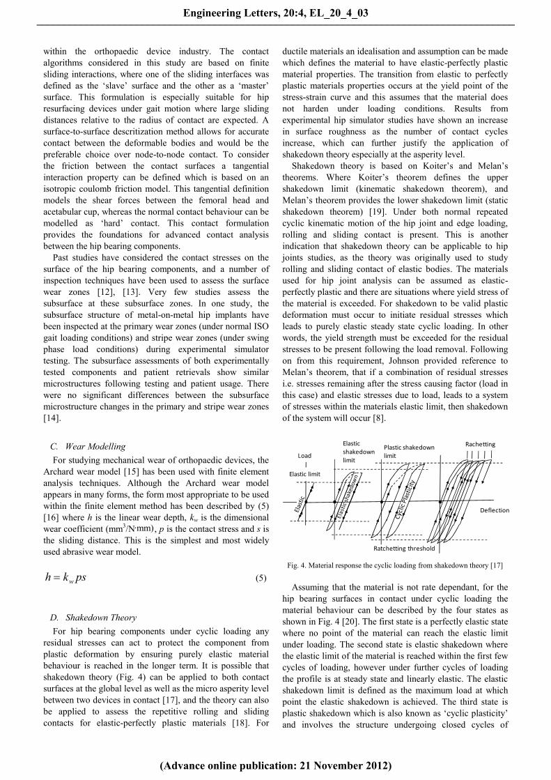
residual stresses can act to protect the component fromplastic deformation by ensuring purely elastic materialbehaviour is reached in the longer term. It is possible thatshakedown theory (Fig. 4) can be applied to both contactsurfaces at the global level as well as the micro asperity levelbetween two devices in contact [17], and the theory can alsobe applied to assess the repetitive rolling and slidingcontacts for elastic-perfectly plastic materials [18]. For
ductile materials an idealisation and assumption can be madewhich defines the material to have elastic-perfectly plasticmaterial properties. The transition from elastic to perfectlyplastic materials properties occurs at the yield point of thestress-strain curve and this assumes that the material doesnot harden under loading conditions. Results fromexperimental hip simulator studies have shown an increasein surface roughness as the number of contact cyclesincrease, which can further justify the application ofshakedown theory especially at the asperity level.
Shakedown theory is based on Koiter’s and Melan’stheorems. Where Koiter’s theorem defines the uppershakedown limit (kinematic shakedown theorem), andMelan’s theorem provides the lower shakedown limit (staticshakedown theorem) [19]. Under both normal repeatedcyclic kinematic motion of the hip joint and edge loading,rolling and sliding contact is present. This is anotherindication that shakedown theory can be applicable to hipjoints studies, as the theory was originally used to studyrolling and sliding contact of elastic bodies. The materialsused for hip joint analysis can be assumed as elastic-perfectly plastic and there are situations where yield stress ofthe material is exceeded. For shakedown to be valid plasticdeformation must occur to initiate residual stresses whichleads to purely elastic steady state cyclic loading. In otherwords, the yield strength must be exceeded for the residualstresses to be present following the load removal. Followingon from this requirement, Johnson provided reference toMelan’s theorem, that if a combination of residual stressesi.e. stresses remaining after the stress causing factor (load inthis case) and elastic stresses due to load, leads to a systemof stresses within the materials elastic limit, then shakedownof the system will occur [8].
Elastic limit
Load
Deflection
RachettingPlastic shakedownlimit
Ratchetting threshold
Elasticshakedownlimit
Fig. 4. Material response the cyclic loading from shakedown theory [17]
Assuming that the material is not rate dependant, for thehip bearing surfaces in contact under cyclic loading thematerial behaviour can be described by the four states asshown in Fig. 4 [20]. The first state is a perfectly elastic statewhere no point of the material can reach the elastic limitunder loading. The second state is elastic shakedown wherethe elastic limit of the material is reached within the first fewcycles of loading, however under further cycles of loadingthe profile is at steady state and linearly elastic. The elasticshakedown limit is defined as the maximum load at whichpoint the elastic shakedown is achieved. The third state isplastic shakedown which is also known as ‘cyclic plasticity’and involves the structure undergoing closed cycles of
Engineering Letters, 20:4, EL_20_4_03
(Advance online publication: 21 November 2012)
______________________________________________________________________________________

plastic deformation. The profile is repeated and a steadystate is reached. The final state is known as incrementalcollapse or rachetting where there is an accumulation of uni-directional plastic strain under cyclic loading.
E. Experimental Simulator Testing of Normal and EdgeLoadingAlthough, previous studies had shown the occurrence of
stripe wear on patient retrievals after many years in service,this same phenomenon was not present on previouslyassessed bearing surfaces following standard in-vitrosimulator testing (Fig. 5). This was due to themicroseperaion kinematics not being considered in the cyclicloading of the hip bearing components [21]. As shown in thestudy by Firkins et al. the kinematics and motions hadsignificant effect on the contact and therefore wear rates ofdevices [22]. Microseperation has more recently beenincorporated into experimental simulator testing. A study ofhip bearing devices were run under cyclic loading withflexion to extension (+30° to -15°) and internal to external(-15° to +15°) rotation of the hip [23].
By assessing the magnitude of component gravimetricwear rates from experimental simulators in-vitro studies andin-vivo patient retrievals, wear rates of metal-on-metal hipresurfacing devices up to 96 mm3/mc (million cycles) havebeen observed. Therefore, the significance of mild andsevere microseparation conditions were observed in currentliterature.
xy
zInward-Outward Rotation
Abduction-Adduction about z-axis
Flexion-ExtensionVertical Loading
Microseperation
Fig. 5. Experimental simulator schematic
III. MATERIALS AND METHODSComputational and numerical methods have been used to
investigate the mechanical contact of hip resurfacing devicesunder normal and edge loading conditions. Two componentsin contact can be modelled using finite element analysis. Fora single load pass (i.e. the 1st cycle) the contact stress, subsurface stress, deformation and strain can be determined.Following the loading of the first cycle, residual stresses can
also occur, and the cyclic process continues until a steadystate has been reached, at this stage an elastic state shouldhave been reached if it has not already during the 1st loadingand contact cycle [24].
A. Computational and Numerical ProcessesA technique has been developed to take patient bone
scans and develop finite element (FE) contact models asdescribed in Fig. 6. The acetabular cup and femoral headcomponents were modelled using SolidWorks computeraided design. These orthopaedic models were combined withpelvis and femur models in an assembly. The associativeinterface between the computer aided design model andfinite element model allowed for geometrical modificationsto be made to the orthopaedic devices. The analysis wasconducted using ABAQUS (Version 6.10-1) in combinationwith user defined subroutines and programming.
DICOM bonemodel scans
Import bone models andcombine with orthopaedic
device
CAD-FE Associativeinterface
Orthopaedicdevice model
FE Analysis (including subroutinesand programming)
Contact, wear andshakedown results
Yes
No
Determine equivalent bone modelelastic modulus
Solid bonemodels
Model and/oranalysisupdates?
Fig. 6. Bone scans to FE contact models
B. Finite Element ModelsA number of finite element models were developed in this
study. Common to all models, the hip resurfacing device wasmodelled nominally with a bearing diameter (df) of 50 mmand diametral clearance (dc) of 80 µm [25]. For a simpledeformable body on rigid body contact model where specific
Engineering Letters, 20:4, EL_20_4_03
(Advance online publication: 21 November 2012)
______________________________________________________________________________________

geometric comparison studies could be made, hipresurfacing components were backed and fully tied to rigidparts referred to as model 1 (shown in Fig. 7). Following onfrom model 1, the elasticity of attached bone was consideredfor the simulation of models 2-4. For all models, it isassumed that full contact and bonding is maintained betweenthe top surface of the acetabular cup and acetablum andlikewise between the bottom surface of the femoral headcomponent and femur. Perfect sphericity of the cup andfemoral head were also assumed. For initial conditions thecup and femoral head bearing centres coincided, and allmodel boundary conditions were subsequently appliedwithin specified time steps.
MicroseperationFully rigid parts
Femoral head
Acetabular cup
Vertical Load
µ = 0.16 (coefficientof friction modelledbetween head and cup)
y
xz
Fig. 7. Assembly of rigid backed components (model 1)
A number of vertical loading magnitudes were alsoconsidered in the study. A vertical load (Fy) of 3900 N wasapplied based on the peak load expected during the walkingcycle, however a stumbling load (Fs) of 11000 N and ISO(International Organization of Standardization) load (FI) of3000 N was also considered. High vertical loads such as Fy
and Fs have been highlighted to occur during patient walkingand stumbling [26]. For model 1 and model 2 themicroseperation was modelled by translating the cup bearingcentre in the lateral direction (i.e. along the anatomicallateral-medial axis) as used in experimental testing methods[23] and a finite element study of edge loading [27]. Inaddition to this method of modelling microseperaton, ‘pure’microseperation was also considered, which more closelyreplicates the theoretical model proposed by Mak, Besong,Jin and Fisher (Fig. 8), where α is the cup inclination angle.The pure microseperation model will be based on arelocation of the femoral head centre both laterally andinferiorly where heal strike causes the head to relocate intothe acetabular cup.
The coefficient of friction (µ) between the head and cupwas modelled as 0.16 based on the friction factor ofCoCrMo on CoCrMo (cobalt chromium molybdenum) inboth bovine serum and synovial fluid [28]. Of all materialcombinations studied by Scholes, Unsworth and Goldsmiththis was the largest friction factor value recorded. Thecoefficient of friction value modelled in finite elementanalysis has been shown to have a negligible effect on thecontact pressure at low values of friction coefficients [25],however, as the surface friction coefficient increases during
the life of the component the subsurface stresses will alsoincrease [29]. Therefore it has been considered in this study.Meshing techniques and element types were selected basedon the geometry of the components and the type of problembeing solved.
For contact modelling where plastic material models wereconsidered [30], current literature has shown that the optionfor selecting a kinematic or isotropic hardening model wouldprovide very similar results [31]. For all contact modelsnormal “hard” contact behaviour was specified and thematerial properties have been obtained from literature assummarised in Table I [32], [33]. The stress-strain curves forASTM F75 cobalt chrome has been provided in Fig. 9 [30].For the application of shakedown theory, elastic-perfectlyplastic material properties were considered. The materialconsidered was ASTM F75 CoCrMo ‘as cast’ material andthe properties were adapted to consider an elastic-perfectlyplastic material model.
x
y
AC1
C2
C3
x
y
S
αC1
C2
C3
0
x’y’ x’y’
α
Fig. 8. Theoretical microseperation model [34]
For the bone model material properties an assessment wasconducted to find an equivalent bone elastic modulus for thefemur (BEF) and pelvis (BEP) as shown in table 1 to provide asimplified material model for the contact analysis. This wasobtained by comparing the model stiffness of a CT femurand pelvis bone scan loaded in all three directions (x,y,z) toobtain BEF and BEP. A sensitivity analysis was carried out ona bone material model between elastic modulus values of3GPa and 25 GPa applied to the pelvis and femur.
TABLE IMATERIAL PROPERTIES
Material Elastic modulus(GPa)
Poisson’sratio Density (kg/m3)
CrCrMo 230 0.3 8270BEF 12.3 0.3 1900BEP 6.1 0.3 1900
The following assumptions can be made for the cobaltchrome to simplify the analysis: isotropic, homogenous andlinear elastic. There is currently no study within literaturewhich assumes cobalt chrome molybdenum to be a perfectlyplastic material. However, for ductile materials anidealisation can be made which defines the material to haveelastic-perfectly plastic materials properties.
By modelling a section of the femur and pelvis theelasticity of these two parts can be considered (Fig. 10) inthe contact analysis in model 2. The modelled bone sizeshave been checked [35] to ensure the models wererepresentative of real specimens. A similar modelling
Engineering Letters, 20:4, EL_20_4_03
(Advance online publication: 21 November 2012)
______________________________________________________________________________________
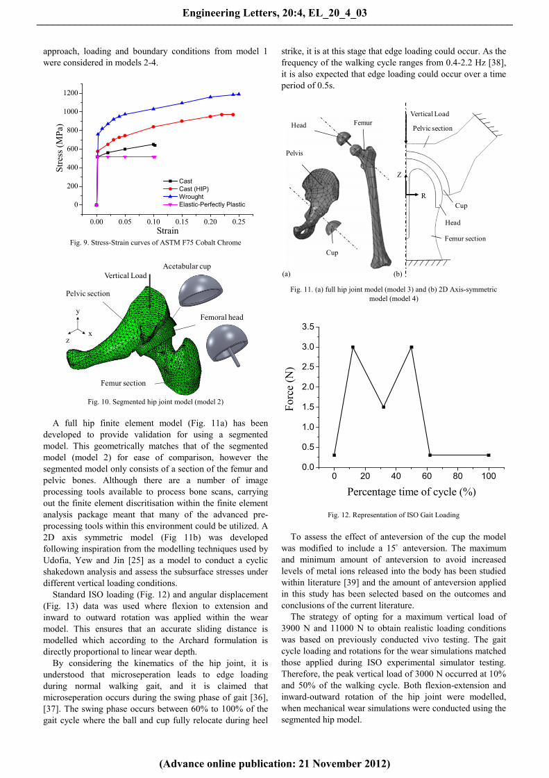
approach, loading and boundary conditions from model 1were considered in models 2-4.
0.00 0.05 0.10 0.15 0.20 0.25
0
200
400
600
800
1000
1200
Stre
ss (M
Pa)
Strain
CastCast (HIP)WroughtElastic-Perfectly Plastic
Fig. 9. Stress-Strain curves of ASTM F75 Cobalt Chrome
Vertical Load
Pelvic section
Femur section
Femoral heady
xz
Acetabular cup
Fig. 10. Segmented hip joint model (model 2)
A full hip finite element model (Fig. 11a) has beendeveloped to provide validation for using a segmentedmodel. This geometrically matches that of the segmentedmodel (model 2) for ease of comparison, however thesegmented model only consists of a section of the femur andpelvic bones. Although there are a number of imageprocessing tools available to process bone scans, carryingout the finite element discritisation within the finite elementanalysis package meant that many of the advanced pre-processing tools within this environment could be utilized. A2D axis symmetric model (Fig 11b) was developedfollowing inspiration from the modelling techniques used byUdofia, Yew and Jin [25] as a model to conduct a cyclicshakedown analysis and assess the subsurface stresses underdifferent vertical loading conditions.
Standard ISO loading (Fig. 12) and angular displacement(Fig. 13) data was used where flexion to extension andinward to outward rotation was applied within the wearmodel. This ensures that an accurate sliding distance ismodelled which according to the Archard formulation isdirectly proportional to linear wear depth.
By considering the kinematics of the hip joint, it isunderstood that microseperation leads to edge loadingduring normal walking gait, and it is claimed thatmicroseperation occurs during the swing phase of gait [36],[37]. The swing phase occurs between 60% to 100% of thegait cycle where the ball and cup fully relocate during heel
strike, it is at this stage that edge loading could occur. As thefrequency of the walking cycle ranges from 0.4-2.2 Hz [38],it is also expected that edge loading could occur over a timeperiod of 0.5s.
Cup
Head
Pelvis
Femur
Femur section
Pelvic section
Head
Cup
Vertical Load
R
Z
Fig. 11. (a) full hip joint model (model 3) and (b) 2D Axis-symmetricmodel (model 4)
0 20 40 60 80 1000.0
0.5
1.0
1.5
2.0
2.5
3.0
3.5
Forc
e (N
)
Percentage time of cycle (%)
Fig. 12. Representation of ISO Gait Loading
To assess the effect of anteversion of the cup the modelwas modified to include a 15˚ anteversion. The maximumand minimum amount of anteversion to avoid increasedlevels of metal ions released into the body has been studiedwithin literature [39] and the amount of anteversion appliedin this study has been selected based on the outcomes andconclusions of the current literature.
The strategy of opting for a maximum vertical load of3900 N and 11000 N to obtain realistic loading conditionswas based on previously conducted vivo testing. The gaitcycle loading and rotations for the wear simulations matchedthose applied during ISO experimental simulator testing.Therefore, the peak vertical load of 3000 N occurred at 10%and 50% of the walking cycle. Both flexion-extension andinward-outward rotation of the hip joint were modelled,when mechanical wear simulations were conducted using thesegmented hip model.
(a) (b)
Engineering Letters, 20:4, EL_20_4_03
(Advance online publication: 21 November 2012)
______________________________________________________________________________________

0 20 40 60 80 100
-20
-10
0
10
20
30A
ngul
ar D
ispl
acem
ent (
deg)
Percentage of cycle time (%)
Angle of flexion (+) or extension (-) ° ± 3 °Angle of adduction (+) or abduction (-) ° ± 3 °Angle of inward (+) or outward (-) ° ± 3 °
Fig. 13. Representation of ISO hip joint angular displacements
C. Wear Increment Methodology DevelopmentContact analysis forms a considerable part of simulating
the mechanical wear of these devices. Two wear simulationstrategies and methodologies were developed. The mostcommonly used method for ablating the mesh followingwear depth calculation is through the use of user definedsubroutines in combination with finite element techniques.This provides mesh control during the adaptive meshingprocedure. In this study, the approach was developed furtherto calculate the linear wear at the end of each analysisincrement, and the finite element mesh to be updated at theend of every increment. Secondly, a method of recordingand saving the contact sliding distance during the analysisincrements has also been developed along with the finiteelement analysis to determine the contact pressures. It isassumed that the wear coefficient obtained experimentally,will cover the complex wear mechanisms occurring duringthe wear process. The process describing the numericalwear process with the finite element method is described inFig. 14 where Φ is the finite element height, hj is the linearwear depth and s is the sliding distance.
FE Input file FEA (Abaqus)
Read InterfaceResults
Apply wear modelCalculate wear depth
Determine wear direction
s ≥ smax
END
Weardepth ≥
Φ
Remeshing
No
Yes
No
Yes
jjj hhh 1
Fig. 14. Numerical wear simulations with the finite element method
FE Input file FEA (Abaqus)
Extract results file
Calculate wear depthmagnitude, sliding distance
and wear direction
Apply wear model throughcoordinate transformations
END
No
Yes
Th
Update meshTotal
number ofcycles?
Fig. 15. Updated wear simulation method
The alternative method to this is using an interface whichextracts data from the finite element analysis results. Thedata is then used to conduct sliding distance magnitude andcyclic wear depth calculations. At predefined cyclic intervalsthe mesh is then updated without the need to use an adaptivemeshing algorithm. This method provides further analysisflexibility and process checking (Fig. 15).
For the proposed mechanical wear simulations andnumber of cycles the total wear depth is calculated for eachnode on the bearing surface as shown in (6). Where hI is thetotal wear depth calculated over the total number ofincrements n for the analysis at each node of the bearingsurface. The total volumetric wear over the testing period isgiven by hT (7), where k is the total number of cycleincrements before the mesh geometry is updated. Thedimensional wear coefficient values have been obtainedfrom literature [40].
n
iiiiI sskph
11 )( (6)
k
iIT hh
1(7)
D. Theoretical Contact and Microseperation ModelsThe finite element model was validated against theoretical
calculations under centred/normal loading conditions. Thesecalculations were based on Hertz contact theory, which areshown in (8) and (9) [25] to calculate the contact radius (cr)and maximum contact stress (po), where R, ν and E are theeffective radius, Poisson’s ratio and modulus of elasticityrespectively.
3
2
213[E
RFc Ir
(8)
223
bFp I
o (9)
To understand and define the distance for onset of rimcontact (rc) an equation has been derived by Mak, Besong,
Engineering Letters, 20:4, EL_20_4_03
(Advance online publication: 21 November 2012)
______________________________________________________________________________________

Jin, and Fisher (10), where c is the bearing radial clearance.[34] This model developed by the authors has been used as abasis for including microseperation within the computationalanalysis. The relocation due to heal strike was modelled byconsidering an initial dislocation of the femoral componentand femur from the centre position.
crc
tan11 (10)
IV. RESULTS
A. Model 1: Rigid Backed ModelBased on the walking gait peak vertical load of 3900 N the
maximum contact pressure was 101 MPa without theinclusion of microseperation. The contact pressure increasedto a maximum of 1284 MPa (Fig. 16) along with 675 MPavon Mises stress when 250 μm of lateral displacement wasapplied in combination with the peak load as shown abovethe rim of the acetabular cup. By considering a lateralreaction force of 500N (in line with experimental simulatortest methods) without any vertical load led to a maximumcontact pressure of 564 MPa, von Mises stress of 456 MPaand maximum principal stress of 431 MPa.
Fig. 16. Rigid backed edge loading contact pressure distribution
The simulation conducted on this model considered onecycle of edge loading, however edge loading could occur ina cyclic manner. When the edge load was removed (i.e.contact removed) the plastic strain was predicted to be lessthan 0.03%. Through the assessments of the subsurfacestresses in the edge loaded region it was found that themaximum residual stress occurred at the subsurface (Fig.17). This subsurface strain profile was obtained through acombination of a peak load and microseperation followingone loading cycle.
Fig. 17. Edge loaded subsurface strain location
Through the assessment of edge loading due to ‘pure’microseperation using an explicit solver, the contact againwas predicted to be initially above the rim of acetabular cup.
A symmetrical profile occurred about the centre of contactand the magnitude decreased as the azimuthal angle φincreased from the centre of contact. The contact radius wasas large as 20˚ from the centre of contact. The maximumcontact distribution did not occur on but above the rimradius of the cup. The contact pressure magnitude decreasedas the polar angle θ increased where contact was observedbelow 7˚ (Fig. 18).
-30 -20 -10 0 10 20 300
50
100
150
200
250
300
350
Con
tact
Pre
ssur
e (M
Pa)
Angle from medial-lateral axis ()
00.170.733.26.95
Polar angle (θ)
0.2˚
0.7˚
3.2˚
7.0˚
0˚
Fig. 18. Edge loading by ‘pure’ microseperation
30 40 50 60
200
300
400
500
600
700
Con
tact
Pre
ssur
e (M
Pa)
Cup inclination angle ()
Fig. 19. Variation of contact pressure against cup inclination angle
By taking advantage of the customisable rigid backedmodel and through an efficient parametric study, the affectof cup inclination angle under ‘pure’ microseperationconditions was observed (Fig. 19). The maximum contactpressure increased as the cup inclination angle increasedfrom 30˚ to 60˚. This range of cup inclination angle wasconsidered to be sufficient to cover the variations betweenpatients following implantation of the bearing devices.
B. Model 2-3: Segmented and Full Hip ModelFor model 2, a 250 µm translation in the lateral direction ledto an edge loading reaction force of 907 N. Based on thewalking gait peak vertical load of 3900N the maximumcontact pressure was 18 MPa without consideration ofmicroseperation (Fig. 20).
As shown on the edge of the acetabular cup, the contactpressure (Fig. 21) and von Mises stress increased to a
Max. Contact pressure = 1284 MPa
Engineering Letters, 20:4, EL_20_4_03
(Advance online publication: 21 November 2012)
______________________________________________________________________________________
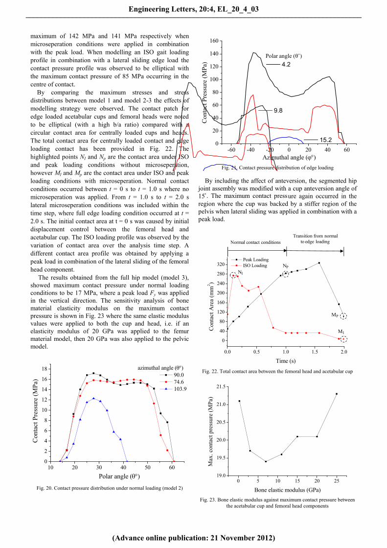
maximum of 142 MPa and 141 MPa respectively whenmicroseperation conditions were applied in combinationwith the peak load. When modelling an ISO gait loadingprofile in combination with a lateral sliding edge load thecontact pressure profile was observed to be elliptical withthe maximum contact pressure of 85 MPa occurring in thecentre of contact.
By comparing the maximum stresses and stressdistributions between model 1 and model 2-3 the effects ofmodelling strategy were observed. The contact patch foredge loaded acetabular cups and femoral heads were notedto be elliptical (with a high b/a ratio) compared with acircular contact area for centrally loaded cups and heads.The total contact area for centrally loaded contact and edgeloading contact has been provided in Fig. 22. Thehighlighted points NI and Np are the contact area under ISOand peak loading conditions without microseperation,however MI and Mp are the contact area under ISO and peakloading conditions with microseperation. Normal contactconditions occurred between t = 0 s to t = 1.0 s where nomicroseperation was applied. From t = 1.0 s to t = 2.0 slateral microseperation conditions was included within thetime step, where full edge loading condition occurred at t =2.0 s. The initial contact area at t = 0 s was caused by initialdisplacement control between the femoral head andacetabular cup. The ISO loading profile was observed by thevariation of contact area over the analysis time step. Adifferent contact area profile was obtained by applying apeak load in combination of the lateral sliding of the femoralhead component.
The results obtained from the full hip model (model 3),showed maximum contact pressure under normal loadingconditions to be 17 MPa, where a peak load Fy was appliedin the vertical direction. The sensitivity analysis of bonematerial elasticity modulus on the maximum contactpressure is shown in Fig. 23 where the same elastic modulusvalues were applied to both the cup and head, i.e. if anelasticity modulus of 20 GPa was applied to the femurmaterial model, then 20 GPa was also applied to the pelvicmodel.
10 20 30 40 50 600
2
4
6
8
10
12
14
16
18
Con
tact
Pre
ssur
e (M
Pa)
Polar angle ()
90.074.6103.9
azimuthal angle ()
Fig. 20. Contact pressure distribution under normal loading (model 2)
-60 -40 -20 0 20 40 600
20
40
60
80
100
120
140
160
Con
tact
Pre
ssur
e (M
Pa)
Azimuthal angle ()
4.29.815.2
-60 -40 -20 0 20 40 600
20
40
60
80
100
120
140
160
Con
tact
Pre
ssur
e (M
Pa)
Azimuthal angle ()
4.29.815.2
-60 -40 -20 0 20 40 600
20
40
60
80
100
120
140
160
Con
tact
Pre
ssur
e (M
Pa)
Azimuthal angle ()
4.29.815.2
-60 -40 -20 0 20 40 600
20
40
60
80
100
120
140
160
Con
tact
Pre
ssur
e (M
Pa)
Azimuthal angle ()
4.29.815.2
Polar angle (θ˚)
Fig. 21. Contact pressure distribution of edge loading
By including the affect of anteversion, the segmented hipjoint assembly was modified with a cup anteversion angle of15̊ . The maximum contact pressure again occurred in theregion where the cup was backed by a stiffer region of thepelvis when lateral sliding was applied in combination with apeak load.
Normal contact conditionsTransition from normal
to edge loading
NI
NP
MP
MI
0.0 0.5 1.0 1.5 2.0
0
40
80
120
160
200
240
280
320
Con
tact
Are
a (m
m2 )
Time (s)
Peak LoadingISO Loading
Fig. 22. Total contact area between the femoral head and acetabular cup
0 5 10 15 20 2519.0
19.5
20.0
20.5
21.0
21.5
Max
. con
tact
pre
ssur
e (M
Pa)
Bone elastic modulus (GPa)Fig. 23. Bone elastic modulus against maximum contact pressure between
the acetabular cup and femoral head components
Engineering Letters, 20:4, EL_20_4_03
(Advance online publication: 21 November 2012)
______________________________________________________________________________________

The mechanical wear prediction for the volumetricmaterial loss due to mechanical wear of femoral head underflexion to extension and internal to external rotation and ISOgait loading conditions was 82 mm3/mc (per million cycles),this was based on the first million cycles of loading. Thiswas the volumetric wear loss for the femoral headcomponents.
C. Shakedown Assessment (Models 1,2 and 4)Based on shakedown maps for line and circular contact
[17], [18] and a friction coefficient of 0.16 the componentremains in an elastic state under contact loading as long asthe load intensity Po/k does not exceed 3 (Fig. 24), where Po
and k are the maximum contact pressure and material shearyield strength respectively. The value of k was calculatedfrom the definition of this value in literature [18]. Based ontheoretical shakedown maps and the maximum contactpressure observed from the analysis, the load intensity of thehip resurfacing devices Po/k was predicted to lie within theelastic region of the shakedown map and not located in theelastic shakedown regions of the shakedown maps.
Load
inte
nsity
P o/k
Coefficient of friction µ
1
0
2
3
4
5
0.1 0.2 0.3 0.4 0.5
Elastic region
Elastic-perfectly plasticshakedown limit
Elastic shakedown region
Figure 24. Shakedown map representation for line contact [17]
0 2x10⁻⁵ 4x10⁻⁵ 6x10-50
2
4
6
8
10
12
14
16
Stre
ss (M
Pa)
Strain
Fig. 25. 2D-Axis symmetric cyclic stress-strain curve during normalloading
TABLE IIMAXIMUM VON MISES STRESS UNDER VERTICAL LOADS
Load Cup (max. stress MPa) Head (max. stress MPa)
FI 34 15Fy 45 21Fs 125 66a
a107 MPa predicted at the base of the femoral head stem
FI
Acetabular cup
Fy
Fs
Femoral headLoad
Figure 26. von Mises stress distributions under vertical loads
By conducting the 2D axis-symmetric cyclic analysisusing model 4, the stress-strain curve (Fig. 25) predicts thehip resurfacing device material to remain within the elasticregion under normal loading conditions. The loading curveshows the first 6 loading cycles.
The subsurface von Mises stress can be observed on thesubsurface of both the acetabular cup and femoral headcomponents (Fig. 26) under FI, Fy and Fs vertical loadingconditions. The locations of maximum von Mises stresseshave been circled and as shown the maximum von Misesstresses occurred below the surface of contact, it was onlywhen a stumbling load Fs was applied that the maximum vonMises stress occurred at the base of the head component(Table II).
V. DISCUSSIONBy comparing the results obtained for all computationalmodels the effect of bone elasticity on the contact stress andvon Mises stress distributions was shown. Any asymmetricalcontact and stress distributions were predicted to be causedby unsymmetrical geometry of the human anatomy as well asthe combination and magnitude of normal and edge loadingconditions. When considering microseperation conditionsalong with a peak vertical load, it was observed that themaximum contact pressure and von Mises stress occurredtowards the anterior end of the acetabular cup and femoral
Engineering Letters, 20:4, EL_20_4_03
(Advance online publication: 21 November 2012)
______________________________________________________________________________________

head. For all three dimensional models, the plastic strainsand stress were predicted to occur above the rim radius ofthe cup which matches the inspections from patient retrievalsand bearing components following experimental simulatortesting with microseperation. The corresponding contactprofile on the femoral head component was also dependentupon the anteversion angle of the implanted cup. Due to thegeometric nature of the femoral head the anteversion of thecup would not have any effect upon the contact pressureprofile and magnitude on the acetabular cup, therefore theeffect of anteversion was only assessed on the femoral head.The contact pressures were also found to be insensitive tobone elastic modulus, even though a large range of E valueswere modelled as a form of methodology verification.
The magnitude of stresses and contact pressures observedmay appear large for model 1 however, the rigidity ofbacking components increased the results by at least a factorof 5 over the results obtained using models 2-4. These highlevels of contact pressure and stress were also been observedby Mak et al. [27]. The maximum stress and therefore plasticstrain was observed below the surface of the material aspredicted by Hertz theory for surfaces in contact with acoefficient less than 0.3. For model 1, the total contact areaunder edge loading conditions was at least 2.7 times lessthan under central/normal contact conditions. This was animportant finding as the contact patch dimensions directlyaffects the linear wear as does the contact pressure accordingto the Archard wear model used to study wear of the bearingsurfaces.
When considering both cyclic gait loading and highstumbling loads no plasticity was observed in models 2-4,therefore, in reality it was predicted that material plasticitywould not occur under normal, edge loading or extremestumbling load conditions. In addition to assessing theplasticity and fracture, fatigue assessments are an importantconsideration for any cyclically loaded component, throughthis study it was deemed that fatigue strength along withfracture toughness of Cobalt Chromium are significantlylarger than bone. The fracture toughness of cobalt-chromium-molybdenum (CoCrMo) could be up to 50 timesgreater than for bone [41]. This high fracture toughnesswould much sooner cause femoral neck fracture [42], [43]before fracture or fatigue failure of the metal-on-metaldevice.
It was possible to assess the reaction forces in the edgeloaded regions to determine the contact stress results atspecific lateral sliding magnitudes. The microseperationdistance of 250 µm was equivalent to a force greater thanthat considered in experimental simulator studies which istypically 200 N to 500 N in magnitude. These observationsalso explain the high values of edge loading contact pressureobserved in model 1. Although the effect of bone geometryon the edge loading contact pressure distribution wasobserved when a combination of lateral sliding and a peakload was modelled, the contact pressured reduced while theedge load was applied during the swing phase load of theISO gait loading cycle.
Based on the maximum contact pressure, calculated valueof k and therefore a low value of load intensity, suggestedthat the component under central and edge loading
conditions would remain within the elastic region of acontact shakedown map, which is a ‘safe’ region for thecomponent to be operating in. Therefore, in terms of the hipresurfacing device’s response to loading, elastic shakedown,plastic shakedown or ratcheting behaviour is unlikely to beobserved, during normal contact conditions, edge loading orstumbling load conditions.
By assessing affect of cup inclination angle under ‘pure’microseperation and relocation, the increases in contactpressure above a 45˚ cup inclination agrees with the clinicalobservations of increased wear rates from patients withimplanted hip resurfacing devices [44], however, it shouldbe noted that this was conducted without any anteversion ofthe acetabular cup.
For the mechanical wear simulations a cyclic ISO loadingprofile was applied in combination with hip rotations.Assumptions were made between the numerical andexperimental strategies to simplify the model. Thesesimulations provided comparative results against thefindings from experimental simulator studies. Thedimensional wear coefficients from current literatureprovided material and application specific values to beapplied to the Archard wear model.
VI. CONCLUSIONA combination of computational, numerical and
theoretical techniques have been used and developed, whichformed the basis of studying the contact mechanics, wearand shakedown of hip resurfacing device. The finite elementmethod was used to build contact models, develop numericalmechanical wear techniques from previous studies andassess the application of shakedown theory to normal andedge loaded hip joint resurfacing devices under differentloading conditions. The severity of edge loading contact wasobserved along with the significance and sensitivity ofresults based on the bone backed anatomical geometry andassembly. Based on the assumptions made in this study andthe modelling conditions to simulate normal and edgeloading for hip joint resurfacing devices, predictions showedthat although cyclic loading is present during the operationof the hip resurfacing devices, elastic shakedown, plasticshakedown or rachetting is not predicted to occur. Theresurfacing device material is predicted to remain operatingwithin the elastic region. It should be noted that thisconclusion is drawn without the direct assessment of asperityshakedown, which will be considered in future studies.
The scope for studying the contact mechanics and wear ofhip resurfacing devices within its designed applications ofbeing implanted into patients is possible without the need forcomplex density based material models. During this study itwas found that an equivalent bone modulus can be usedwithout the need for refinement as the affect on producinghighly varied contact pressures was negligible.
The modelling of microseperation was carried out in twodistinct and separate ways. Both lateral sliding and ‘pure’microseperation were applied and the contact stress,subsurface stress, strain and shakedown were assessed.Laxity of the joint was simulated based on a theoretical
Engineering Letters, 20:4, EL_20_4_03
(Advance online publication: 21 November 2012)
______________________________________________________________________________________
microseperation model which provides further explanationof the increasing wear rates as observed by in-vitro studiesand patient retrievals. Both microseperation simulationmodels showed an increase of contact stress by at least afactor of 2 over normal or centrally loaded hip resurfacingdevices, depending on a number of factors including theanteversion of the acetabular cup and load magnitude. Thislevel of contact stress increase compares closely to the levelof wear rate increase from in-vitro experimental simulatorstudies which includes microseperation.
The Archard wear model in combination with the FEsolver provided a basis for predicting the wear of the bearingsurface. The methodological approach adopted in this studymeant that numerical and process checks could be performedat every step to ensure that the developed simulationsprovided understandable results. Further work is required toreduce the total number of increments to update the finiteelement mesh more regularly, this will in turn allow for acontact pressure distribution which is more dependant uponthe worn surface geometry. The wear simulations shouldalso consider the variation in dimensional wear coefficientthroughout the cyclic life of the bearing components.
In this study modelling verification, comparative solutionsto other studies and theoretical models have been developedfor centered contact conditions; however, further work isrequired to develop theoretical and computational models tomore accurately simulate and assess the effects of realpatient specific consequences of edge loading andmicroseperation on hip resurfacing devices. The kinematicsof these conditions during human joint motion should beconsidered in more depth if simulations are to accuratelymodel these problems. Overall, using a combination oftechniques and theoretical models has shown to be beneficialin developing numerical analysis of hip resurfacing devicesunder specific conditions.
REFERENCES
[1] J. G. Bowsher, T. K. Donaldson, P. A. Williams, and I. C. Clarke,"Surface Damage After Multiple Dislocations of a 38-mm-Diameter,Metal-on-Metal Hip Prosthesis," Journal of Arthroplasty, vol. 23,pp. 1090-1096, Oct 2008.
[2] W. L. Walter, G. M. Insley, W. K. Walter, and M. A. Tuke, "Edgeloading in third generation alumina ceramic-on-ceramic bearings,"Journal of Arthroplasty, vol. 19, pp. 402-413, Jun 2004.
[3] S. Williams, T. D. Stewart, E. Ingham, M. H. Stone, and J. Fisher,"Metal-on-metal bearing wear with different swing phase loads,"Journal of Biomedical Materials Research Part B-AppliedBiomaterials, vol. 70B, pp. 233-239, Aug 2004.
[4] M. Manaka, I. C. Clarke, K. Yamamoto, T. Shishido, A. Gustafson,and A. Imakiire, "Stripe wear rates in alumina THR - Comparison ofmicroseparation simulator study with retrieved implants," Journal ofBiomedical Materials Research Part B-Applied Biomaterials, vol.69B, pp. 149-157, May 2004.
[5] I. J. Leslie, S. Williams, G. Isaac, E. Ingham, and J. Fisher, "HighCup Angle and Microseparation Increase the Wear of Hip SurfaceReplacements," Clinical Orthopaedics and Related Research, vol.467, pp. 2259-2265, 2009.
[6] R. A. Poggie, T. R. Turgeon, and R. D. Coutts, "Failure analysis of aceramic bearing acetabular component," Journal of Bone and JointSurgery-American Volume, vol. 89A, pp. 367-375, Feb 2007.
[7] M. Ali and K. Mao, "Modelling of hip resurfacing device contactunder central and edge loading conditions," Lecture Notes inEngineering and Computer Science: Proceedings of The WorldCongress on Engineering 2012, WCE 2012, 4-6 July, London, U.K.pp. 2054-2059, 2012.
[8] K. L. Johnson, Contact mechanics / K.L. Johnson. Cambridge :Cambridge University Press, 1985.
[9] J. E. Shigley, Mechanical engineering design / Joseph E. Shigley,Charles R. Mischke, 6th ed. ed. Boston :: McGraw Hill, 2001.
[10] H. F. El'Sheikh, B. J. MacDonald, and M. S. J. Hashmi, "Finiteelement simulation of the hip joint during stumbling: a comparisonbetween static and dynamic loading," Journal of MaterialsProcessing Technology, vol. 143-144, pp. 249-255, 2003.
[11] A. Z. Senalp, O. Kayabasi, and H. Kurtaran, "Static, dynamic andfatigue behavior of newly designed stem shapes for hip prosthesisusing finite element analysis," Materials & Design, vol. 28, pp.1577-1583, 2007.
[12] T. Tateiwa, I. C. Clarke, G. Pezzotti, L. Sedel, T. Kumakura, T.Shishido, et al., "Surface micro-analyses of long-term worn retrieved"Osteal (TM)" alumina ceramic total hip replacement," Journal ofBiomedical Materials Research Part B-Applied Biomaterials, vol.83B, pp. 562-570, Nov 2007.
[13] S. Williams, A. Schepers, G. Isaac, C. Hardaker, E. Ingham, D. vander Jagt, et al., "The 2007 Otto Aufranc Award - Ceramic-on-metalhip arthroplasties - A comparative in vitro and in vivo study,"Clinical Orthopaedics and Related Research, pp. 23-32, Dec 2007.
[14] R. Pourzal, R. Theissmann, S. Williams, B. Gleising, J. Fisher, andA. Fischer, "Subsurface changes of a MoM hip implant belowdifferent contact zones," Journal of the Mechanical Behavior ofBiomedical Materials, vol. 2, pp. 186-191, Apr 2009.
[15] J. F. Archard, "Contact and Rubbing of Flat Surfaces," Journal ofApplied Physics, vol. 24, pp. 981-988, 1953.
[16] T. A. Maxian, T. D. Brown, D. R. Pedersen, and J. J. Callaghan, "Asliding-distance-coupled finite element formulation for polyethylenewear in total hip arthroplasty," Journal of Biomechanics, vol. 29, pp.687-692, 1996.
[17] J. A. Williams, "The influence of repeated loading, residual stressesand shakedown on the behaviour of tribological contacts," TribologyInternational, vol. 38, pp. 786-797, 2005.
[18] A. R. S. Ponter, H. F. Chen, M. Ciavarella, and G. Specchia,"Shakedown analyses for rolling and sliding contact problems,"International Journal of Solids and Structures, vol. 43, pp. 4201-4219, 2006.
[19] J. A. Williams, I. N. Dyson, and A. Kapoor, "Repeated loading,residual stresses, shakedown, and tribology," Journal of MaterialsResearch, vol. 14, pp. 1548-1559, Apr 1999.
[20] K. L. Johnson, "The application of shakedown principles in rollingand sliding contact," Eur. J. Mech., A/Solids, vol. 11, pp. pp155-172, 1992.
[21] T. Shishido, I. C. Clarke, P. Williams, M. Boehler, T. Asano, H.Shoji, et al., "Clinical and simulator wear study of alumina ceramicTHR to 17 years and beyond," Journal of Biomedical MaterialsResearch Part B-Applied Biomaterials, vol. 67B, pp. 638-647, Oct2003.
[22] P. J. Firkins, J. L. Tipper, E. Ingham, M. H. Stone, R. Farrar, and J.Fisher, "Influence of simulator kinematics on the wear of metal-on-metal hip prostheses," Proceedings of the Institution of MechanicalEngineers Part H-Journal of Engineering in Medicine, vol. 215, pp.119-121, 2001.
[23] T. Stewart, J. Tipper, R. Streicher, E. Ingham, and J. Fisher, "Long-term wear of HIPed alumina on alumina bearings for THR undermicroseparation conditions," Journal of Materials Science-Materials in Medicine, vol. 12, pp. 1053-1056, 2001.
[24] S. K. Wong, A. Kapoor, and J. A. Williams, "Shakedown limits oncoated surfaces," Thin Solid Films, vol. 292, pp. 156-163, 1997.
[25] I. J. Udofia, A. Yew, and Z. M. Jin, "Contact mechanics analysis ofmetal-on-metal hip resurfacing prostheses," Proceedings of theInstitution of Mechanical Engineers Part H-Journal of Engineeringin Medicine, vol. 218, pp. 293-305, 2004.
[26] G. Bergmann, F. Graichen, A. Rohlmann, A. Bender, B. Heinlein,G. N. Duda, et al., "Realistic loads for testing hip implants," Bio-Medical Materials and Engineering, vol. 20, pp. 65-75, 2010.
[27] M. Mak, Z. Jin, J. Fisher, and T. D. Stewart, "Influence ofAcetabular Cup Rim Design on the Contact Stress During EdgeLoading in Ceramic-on-Ceramic Hip Prostheses," The Journal ofArthroplasty, vol. 26, pp. 131-136, 2011.
[28] S. C. Scholes, A. Unsworth, and A. A. J. Goldsmith, "A frictionalstudy of total hip joint replacements," Physics in Medicine andBiology, vol. 45, pp. 3721-3735, Dec 2000.
[29] J. Farley, "Development of a Computational Method of Low CycleFatigue Prediction for Multi-Layer Surfaces under Rolling/SlidingConatact Conditions," Ph.D. dissertation, School of Engineering andDesign, Brunel University, 2008.
Engineering Letters, 20:4, EL_20_4_03
(Advance online publication: 21 November 2012)
______________________________________________________________________________________

[30] Materials and Coatings for Medical Devices: Cardiovascular: ASMInternational, 2009.
[31] Y. Zait, V. Zolotarevsky, Y. Kligerman, and I. Etsion, "MultipleNormal Loading-Unloading Cycles of a Spherical Contact UnderStick Contact Condition," Journal of Tribology-Transactions of theAsme, vol. 132, p. 7, Oct 2010.
[32] R. Hodgskinson and J. D. Currey, "Young modulus, density andmaterial properties in cancellous bone over a large density range,"Journal of Materials Science-Materials in Medicine, vol. 3, pp.377-381, 1992.
[33] M. Dalstra, R. Huiskes, and L. Vanerning, "Development andvalidation of a 3-dimensional finite-element model of the pelvisbone," Journal of Biomechanical Engineering-Transactions of theAsme, vol. 117, pp. 272-278, 1995.
[34] M. M. Mak, A. A. Besong, Z. M. Jin, and J. Fisher, "Effect ofmicroseparation on contact mechanics in ceramic-on-ceramic hipjoint replacements," Proceedings of the Institution of MechanicalEngineers Part H-Journal of Engineering in Medicine, vol. 216, pp.403-408, 2002.
[35] D. G. Steele and C. A. Bramblett, The Anatomy and Biology of theHuman Skeleton: Texas A&M University Press, 1988.
[36] A. V. Lombardi, T. H. Mallory, D. A. Dennis, R. D. Komistek, R. A.Fada, and E. J. Northcut, "An in vivo determination of total hiparthroplasty pistoning during activity," Journal of Arthroplasty, vol.15, pp. 702-709, Sep 2000.
[37] D. A. Dennis, R. D. Komistek, E. J. Northcut, J. A. Ochoa, and A.Ritchie, ""In vivo" determination of hip joint separation and theforces generated due to impact loading conditions," Journal ofBiomechanics, vol. 34, pp. 623-629, 2001.
[38] S. Affatato, A. Spinelli, M. Zavalloni, C. Mazzega-Fabbro, and A.Viceconti, "Tribology and total hip joint replacement: Currentconcepts in mechanical simulation," Medical Engineering &Physics, vol. 30, pp. 1305-1317, Dec 2008.
[39] D. J. Langton, A. P. Sprowson, S. Jameson, T. J. Joyce, M. Reed, P.Partington, et al., "Blood metal ion concentrations post hipresurfacing arthroplasty: a comparison study of the articularsurfacereplacement and Birmingham hip resurfacing devices,"Journal of Bone & Joint Surgery, British Volume, vol. 92-B, pp.390-390, 2010.
[40] F. Liu, I. Leslie, S. Williams, J. Fisher, and Z. Jin, "Development ofcomputational wear simulation of metal-on-metal hip resurfacingreplacements," Journal of Biomechanics, vol. 41, pp. 686-694,2008.
[41] R. E. Smallman and R. J. Bishop, "Modern Physical Metallurgy andMaterials Engineering - Science, Process, Applications (6thEdition)," ed: Elsevier, 1999.
[42] H. Sharma, B. Rana, C. Watson, A. Campbell, and B. Singh,"Femoral neck fractures complicating metal-on-metal resurfacedhips: a report of 2 cases," Journal of Orthopaedic Surgery2005;13(1):69-72, 2005.
[43] D. R. Marker, T. M. Seyler, R. H. Jinnah, R. E. Delanois, S. D.Ulrich, and M. A. Mont, "Femoral neck fractures after metal-on-metal total hip resurfacing," Journal of Arthroplasty, vol. 22, pp.66-71, 2007.
[44] A. J. Hart, P. Buddhdev, P. Winship, N. Faria, J. J. Powell, and J. A.Skinner, "Cup inclination angle of greater than 50 degrees increaseswhole blood concentrations of cobalt and chromium ions aftermetal-on-metal hip resurfacing," Hip Int, vol. 18, pp. 212-9, Jul-Sep2008.
Engineering Letters, 20:4, EL_20_4_03
(Advance online publication: 21 November 2012)
______________________________________________________________________________________