Embed Size (px)
Citation preview
Contact 6
User & Installation Manual
V1.0

EN / CZone® Contact 6 User & Installation Manual 2
Copyright
This document is copyright 2018 under the Creative Commons agreement. Rights are granted to research and
reproduce elements of this document for non-commercial purposes on the condition that BEP is credited as the source.
Electronic re-distribution of the document in any format is restricted, to maintain quality and version control.
Important
BEP strives to ensure all information is correct at the time of printing. However, the company reserves the right to change
without notice any features and specifications of either its products or associated documentation.
Translations: In the event that there is a difference between a translation of this manual and the English version, the
English version should be considered the official version.
It is the owner’s sole responsibility to install and operate the device in a manner that will not cause accidents, personal
injury or property damage.
Use Of This Manual
Copyright © 2018 BEP Marine. All rights reserved.Reproduction, transfer, distribution or storage of part or all of the
contents in this document in any form without the prior written permission of BEP Marine is prohibited.This manual
serves as a guideline for the safe and effective operation, maintenance and possible correction of minor malfunctions
of the Contact 6.

3 EN / CZone® Contact 6 User & Installation Manual
TABLE OF CONTENTS
1 OVERVIEW 4
Description 4
Features 4
Hardware Overview 5
LED Indicators 6
Labelling 7
Pinout 7
Basic System Diagrams 8
Output Configurations 9
2 DESIGN 10
3 INSTALLATION 10
Things You Need 10
Environment 10
TE connector kit 11
Mounting 11
Plugging 12
Connections 12
Set Dipswitch 13
Fit Cover 13
Initial Power Up 14
Relay Manual Override Instructions 14
4 SPECIFICATIONS 15
Technical Specifications 15
Dimensions 16
5 ORDERING INFORMATION 16
6 EC DECLARATION OF CONFORMITY 17
Table of Figures
Figure 1. Contact 6 cover on .................................................................................................................... 5
Figure 2. Contact 6 no cover .................................................................................................................... 5
Figure 3. Basic System Diagram for Contact 6 Fused ............................................................................. 8
Figure 4. Basic System Diagram for Contact 6 Non Fused ..................................................................... 8
Figure 5. TE Pro Crimper ....................................................................................................................... 10

EN / CZone® Contact 6 User & Installation Manual 4
1 OVERVIEW
DESCRIPTION
The CZone Contact 6 is an entry level digital switching module that houses 6 dry contact relays, fully controllable from
any CZone interface or compatible Multi Function Display. The isolated relays allow a mix of positive and negative
switching and can also be configured to control reversing motors. Core CZone features such as Modes & timers are all
possible with the Contact 6.
FEATURES
• Entry level digital switching module for Marine and RV applications
• Stand alone or networked with other CZone products
• Compatible with CZone integrated Multi Function Displays (MFD’s)
• Six independent relay channels with positive, negative and reversing motor control
• Uses proven CZone technology
• Internal auto-resetting fuses (fused version only)
• Electronic relay bypass switch
• Status LED’s/fault codes for all channels
• IPx5 ingress protection
• NMEA2000 compliant
5 EN / CZone® Contact 6 User & Installation Manual
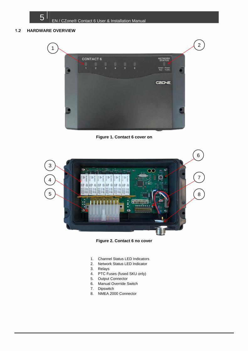
1. Channel Status LED Indicators
2. Network Status LED Indicator
3. Relays
4. PTC Fuses (fused SKU only)
5. Output Connector
6. Manual Override Switch
7. Dipswitch
8. NMEA 2000 Connector
HARDWARE OVERVIEW
Figure 1. Contact 6 cover on
Figure 2. Contact 6 no cover
2 1
6
3
4
5
7
8

EN / CZone® Contact 6 User & Installation Manual 6
LED INDICATORS
1. Circuit Status LED’s
Colour Description
Extinguished Channel Off
Green Solid On Channel On
Green Slow Flash Manual Override Mode
1 Green Flash Module Not Configured
2 Green Flash Configuration Conflict
3 Green Flash DIP Switch Conflict
4 Green Flash Memory Failure
5 Green Flash No Modules Detected
9 Green Flash Missing Commander
2. Network Status LED
Colour Description
Extinguished Network Power Disconnected
Green Network Power Connected
Red Flash Network traffic
2 1

7 EN / CZone® Contact 6 User & Installation Manual
LABELLING
The Contact 6 is supplied with a blank output label. Once system is designed, the output names should be written next
to the channel number they are physically wired to. The label should then be placed on the top cover.
PINOUT
18 17 16 15 14 13 12 11 10
9 8 7 6 5 4 3 2 1
Pinout (Looking at face of PCB connector)
1. CH6 C
2. CH6 NC
3. CH5 C
4. CH4 C
5. CH4 NC
6. CH3 C
13. CH4 NO
14. CH3 NC
15. CH3 NO
16. CH2 NO
17. CH1 NC
18. CH1 NO
7. CH2 C
8. CH2 NC
9. CH1 C
10. CH6 NO
11. CH5 NC
12. CH5 NO

EN / CZone® Contact 6 User & Installation Manual 8
BASIC SYSTEM DIAGRAMS
Figure 3. Basic System Diagram for Contact 6 Fused
Figure 4. Basic System Diagram for Contact 6 Non Fused
Important: for ABYC applications, external fusing may be required
CZone Contact 6
Batt Isolator
12V BATTERY
Neg Bar
Main Fuse
-+
Pos Bus Bar Neg Bus Bar
NMEA 2000
Network
Plug
Gland
Load 1
Load 2
Load 3
Load 4
Load 5
Load 6
CZone Contact 6
Batt Isolator
12V BATTERY
Neg Bar
Fuse Block
-+
Main Fuse
Neg Bus Bar
NMEA 2000
Network
Plug
Gland
Load 1
Load 2
Load 3
Load 4
Load 5
Load 6

9 EN / CZone® Contact 6 User & Installation Manual
OUTPUT CONFIGURATIONS
M
CNC
NO
NC
NO
Relay 1 Relay 2
12V + GND
NC
NO
Relay
C
C
Light
12V + GND
NC
NO
Relay
C To Negative Output
GND
POSITIVE OUTPUT
NEGATIVE OUTPUT
REVERSING MOTOR OUTPUT

EN / CZone® Contact 6 User & Installation Manual 10
2 DESIGN
• Make a list of all outputs to be wired to the Contact 6 and assign each of them to one of the 6 channels (refer
to 1.7 for supported output configurations).
• Select the appropriate Contact 6 SKU for the application (refer to 4.0 for detailed specifications):
o Contact 6 Fused – 12V loads only, maximum 7.5A per channel
o Contact 6 Non Fused - 12V/24V loads, maximum 9A per channel
• Ensure continuous current draw of each connected load does not exceed maximum channel rating, if using
the Contact 6 Non Fused SKU ensure appropriately rated external fuses are used.
• Ensure the maximum continuous current of all loads does not exceed the 30A total module current
• Ensure all cables running to Contact 6 connector are 16AWG (1.0-1.5mm²).
3 INSTALLATION
THINGS YOU NEED
• Contact 6 module
• TE contacts and connector
• 4 x 8G or 10G (4mm or 5mm) self-tapping screws or bolts for mounting Contact 6 to surface
• TE Pro-Crimper (part #1976444-1) or generic crimp tool for 16AWG (1.0-1.5mm²) uninsulated terminals
• NMEA2000 drop cable and T-connector
• Electrical Tools
Figure 5. TE Pro Crimper
ENVIRONMENT
Obey the following stipulations during installation:
• Ensure the Contact 6 is located in an easily accessible location and indicator LED’s are visible
• Ensure circuit label is fitted and all channels labelled correctly
• Ensure Contact 6 is mounted either vertically or horizontally
• Ensure there is sufficient clearance above the Contact 6 to allow the cover to be removed.
• Ensure there is at least 10mm clearance around the sides and top of the Contact 6

11 EN / CZone® Contact 6 User & Installation Manual
TE CONNECTOR KIT
If you have purchased the Contact 6 module that includes the TE connector kit (part # 80-911-0144-00), check all
components are in the bag before proceeding. Alternatively, the TE contacts and connector can be purchased from a
TE distributor by using the part numbers below.
Image Part Number Description Quantity
1-1969614-8 TE AMP, VAL-U-LOK 18 Pin Connector 1
1586841-1 TE AMP, VAL-U-LOK Socket Contact 16AWG
Suitable for 16AWG (1.0-1.5mm²) cable 18
MOUNTING
1. Remove the Contact 6 top cover and locate the 4 mounting screw locators as shown above.
2. Place the Contact 6 on a solid, flat surface.
3. Screw the Contact 6 to the surface with 4 x 8G or 10G (4mm or 5mm) self-tapping screws or bolts (not
supplied).

EN / CZone® Contact 6 User & Installation Manual 12
PLUGGING
1. Strip and crimp all cables with TE contact and crimp tool.
2. Insert the contacts into TE connector following the pinout in chapter 1.5. Also refer to the load list created earlier
to ensure each load is connected to the correct channel and plug position.
3. Ensure all contacts are locked securely in place.
4. Fit gland over cables one slot at a time. Ensure correct orientation of gland, ‘TOP’ label should be at top of
module as per above image.
CONNECTIONS
1. Insert plug in to receptacle in module and ensure cable gland is seated correctly.
2. Connect an NMEA2000 drop cable from Contact 6 to an NMEA2000 backbone. Ensure the NMEA2000 network
is properly terminated and connected to a 12V power source (do not power up network yet).
1
2

13 EN / CZone® Contact 6 User & Installation Manual
SET DIPSWITCH
Using a small flat blade screwdriver carefully set the dipswitch on the Contact 6. The dipswitch number must be unique
for all modules on the CZone network and must match the dipswitch setting in the configuration to function correctly.
The example below shows a dipswitch setting of 01101100 where 0 = Off and 1 = On
FIT COVER
1. Clip top cover on to Contact 6 module (ensure top seal is still in place).
2. Screw top cover on with 4 x supplied mounting screws in locators shown in above image.

EN / CZone® Contact 6 User & Installation Manual 14
INITIAL POWER UP
1. Check plug is securely in place and NMEA connection is tight.
2. Ensure the Contact 6’s top cover is screwed securely in place and seal is seated properly.
3. Power up the NMEA2000 network.
4. Check that the NMEA2000 Network LED lights up. It may also be flashing if other devices are present and
transmitting data.
5. Turn the switch/circuit breaker on supplying power to the outputs.
6. Check the circuit’s status LED’s for each individual circuit. Refer to LED codes to diagnose any faults which
need to be rectified.
7. Check the software version on the Contact 6 with the CZone Configuration Tool and update if necessary.
8. Write configuration file to the Contact 6 and the rest of the CZone modules on the system (Refer to the CZone
Configuration Tool Instructions for details on how to configure the Contact 6).
9. Test all outputs for configured functionality.
RELAY MANUAL OVERRIDE INSTRUCTIONS
Follow the below steps to manually control each relay. To use manual override the Contact 6 must have 12V network
power.
1. To enter manual override mode, hold down manual override switch for 5 seconds until channel 1 status LED
starts flashing then release.
2. Short press the button to cycle to the desired relay channel.
3. Hold the button for 2 seconds and release to turn selected relay ON or OFF.
4. Repeat step 2 and 3 for any other relays.
5. To exit manual override mode hold the manual override switch for 5 seconds until selected channel stops
flashing. The relays will return to their previously networked controlled state.

15 EN / CZone® Contact 6 User & Installation Manual
4 SPECIFICATIONS
TECHNICAL SPECIFICATIONS
Model Contact 6 Fused Contact 6 Non Fused
Part numbers 80-911-0139-00, 80-911-0140-00 80-911-0155-00, 80-911-0156-00
Output Channels 6 x 10A SPDT (Single Pole Double Throw) Dry Contact Relays
6 x 10A SPDT (Single Pole Double Throw) Dry Contact Relays
Max Channel Current
7.5A 9A
Circuit Protection 6 x 7.5A PTC Fuses (auto-reset) None (must be fused externally)
Circuit Bypass Yes (electronic) – requires NMEA Power Yes (electronic) – requires NMEA Power
Output Voltage Up to 16VDC Up to 30VDC
NMEA Voltage 9-16VDC 9-16VDC
Maximum Module Current
30A 30A
Contact Spec TE AMP Val-U-LOK 18-way (Part #1-1969614-8)
TE AMP Val-U-LOK 18-way (Part #1-1969614-8)
Socket Spec TE AMP Val-U-LOK socket (Part # 1586841) TE AMP Val-U-LOK socket (Part # 1586841)
Max Contact Cable Size
16AWG (1 to 1.5mm²) 16AWG (1 to 1.5mm²)
Ingress Protection IPX5 IPX5
Communication NMEA2000 NMEA2000
Operating Temperature
-15°C to 55°C (5°F to 131°F) -15°C to 55°C (5°F to 131°F)
Compliance CE, RCM, NMEA, ISO8846/SAEJ1171 Ignition Protected
CE, RCM, NMEA, ISO8846/SAEJ1171 Ignition Protected
Module Dimensions (H x W x D)
100 x 156 x 42mm (3.94 x 6.14 x 1.65”) 100 x 156 x 42mm (3.94 x 6.14 x 1.65”)
Module Weight 257g 257g

EN / CZone® Contact 6 User & Installation Manual 16
DIMENSIONS
5 ORDERING INFORMATION
Contact 6 Part Numbers and Accessories
Part Number Description
80-911-0139-00 CZone Contact 6 Fused Interface Only
80-911-0140-00* CZone Contact 6 Fused with Seals & Plug
80-911-0144-00 Plug Pack for Contact 6
80-911-0145-00 Cable Gland for Contact 6
80-911-0155-00 CZone Contact 6 Non Fused Interface Only
80-911-0156-00* CZone Contact 6 Non Fused with Seals & Plug
*Kit includes 80-911-0144-00 and 80-911-0145-00

17 EN / CZone® Contact 6 User & Installation Manual
6 EC DECLARATION OF CONFORMITY
We,
Power Products LLC
Mailing Address:
BEP Marine LTD
PO Box 101-739 NSMC
Auckland 0632, New Zealand
Street Address:
42 Apollo Drive
Rosedale,
Auckland, 0632, New Zealand
Declare under our sole responsibility that the products:
• 80-911-0139-00 – CZone Contact 6 Fused Interface Only
• 80-911-0140-00 – CZone Contact 6 Fused with Seals & Plug
• 80-911-0155-00 – CZone Contact 6 Non Fused Interface Only
• 80-911-0156-00 – CZone Contact 6 Non Fused with Seals & Plug
To which this declaration related, is in conformity with the following standards or other normative documents:-
EMC : EN 60945:2002:2002
Maritime navigation and radiocommunication equipment and systems
Albany, New Zealand, 13 April 2018


![combi - Enerdrive Independent Power Solutionsenerdrive.com.au/wp-content/uploads/ePRO-Combi-Web-Rev01.pdf · Combi Inverter / Charger Series ... [ASB] < 10W [2.0W] < 12W](https://img.dokumen.tips/doc/110x75/5ac647de7f8b9a2b5c8e1545/combi-enerdrive-independent-power-inverter-charger-series-asb-10w-20w.jpg)