Embed Size (px)
Citation preview

CONT’ACT-STRESS PHENOMENA IN NUMERICAL SIMULATION OF UNIDIRECTIONALLY-REINFORCED
COMPOSITE BEAMS
W. K. WNIENDA and A. F. SALIIEB
Civil Engineering Repartment, The University of Akron, Akron, OH 443254905, U.S.A.
(Received 8 September I992)
Abstract-The contact-stress phenomena are known to have significant effects on the response of anisotropic composites. In particutar, the numerical results demonstrating these phenomena are reported here for twe classes of ~~di~tj~naIl~-re~f~~ composite structures. The first is the pro&m of an in&&e half-plane subjected to two interacting forces, wherein the ‘exact’ solution is obtained using the Fourier integrat technique. In the second, numericai finite element method (FEM) simulations are given for the three- and four-point bending tests of short composite beams.
Beam tests are perhaps the most widely-used tech- niques for characterizing composite properties. For example, the flexural test method is recommended in ASTM Standard D-790, and the interlaminar, short- beam, shear test is employed in ASTM Standard D-2344. In addition, fatigue and fracture behavior of composites can be investigated using three- and four-point bending beam tests.
In all the above test methods, classical beam theories are often utilized as a basis for data analysis and reduction. However, it has been long recognized that such simpiifred approaches are inadequate, especially when applied to the case of strosgly- anisotropic elastic continua [l---l 51, e.g. strong-fiber reinforced composites. This is mainly due to the fact that local stress, or end effects [e.g. 1,2] are com- pletely neglected in str~gth-of-mate~a~s formulas of this type. For s~ongl~~i~~opic materials, with typically large values for the ratio of the mod&,
&&f&T1 where Eu and GLjr are the longitudinal (along the fiber direction) Young’s modulus, and shear modulus, respectively, the currently available order-of-magnitude estimates [ 11 indicate that the e~~~~~r~~~~e &cuy or Ioad dl~~~~~ length wet which significant local stress effects persist is far greater than that for isotropic materials; i.e. pro- portional to the square root of the above moduli ratio in case of plane anisotropic problems.
The physical implication of this ‘stress channeling’ phenomenon [2], in the context of composite beam teats (e.g. under three- or four-point bending con- ditions), is that the co~f~~t-~tfe~~ developed under the concentrated forces will significantly affect the conditions found at large distances away, in particu- lar both the magnitude and location of maximum
(flexural) tensile stress will be inffuenced greatly. This in turn will have a direct bearing on predicting the location of crack initiation and its subsequent propagation. In fact, it is our objective in the present paper to investigate, both analytically as well as numerically, the effects of these contact stresses in composite beams reinforced u~dir~~ona~ly by generally-oriented fibers. However, before proceeding to this main development, a brief literature review of pertinent works on contact stresses is given in the sequel.
Starting with the C%Irly solutions by Timoshenko 1163, it was noted that the stresses under Aexural conditions are significantly different from beam-theory results, and he offered some of the analytical techniques to account for the contact stresses. Lekhnitskii [ 171 obtained the contact-stress field for the orthotropic half plane loaded by a concentrated force at the edge. He observed that the stress distribution depends on the ratio of ortho- topic moduli {i.e. E&En7 where Em is the elastic Young’s modulus transverse to the fibers) in the case of 0” and 90” of fiber orientation. Green and Zerna [ 181 showed the complex potential solution for the general anisotropic case. However, they presented the stress distribution for the cases restricted to orthotropic and isotropic materials.
Orange [I51 analyzed influence of contact stresses on the initiation and propagation of small cracks in an isotropic beam, thus demonstrating their sign& cant influence on the stress field even in this isotropic case. Furthermore, in a series of papers by Wh~t~y et a!. [S--5] and Browning et al: fq, the more sign& cant influence of contact stresses in orthotopic beams was clearly shown.
The contact stress problems for isotropic and orthotopic beams was also addressed by
277

278 W. K. Brnrs~nn and A. F. SALEEB
Sankar [13, 141. He proposed to use an approximate Green’s function for surface displacements to account for the additional deformation due to the contact stresses in the beam.
In a number of papers[99l2] investigating accu- racy of flexural tests for characterizing composite materials and low-velocity impact force estimation, it was found necessary to account for ‘corrections’ due to contact stresses. For example, in Sun and Chattapadhyay [9], it was assumed that the local effects due to the impacting body can be approxi- mated by static contact behavior giving the impact force history. In other cases, three point static indentation tests provided information on the impact resistance of a composite laminate [IO].
Finally, an outline of the remainder of the paper is given as follows. The exact solution for the anisotropic composite half plane with generally- oriented fibers (i.e. angle D with respect to the plane boundary) under a single concentrated force is obtained in Sec. 2 using the Fourier integral method. Employing the principle of superposition, this is further extended in Sec. 3 to study the interactions between two concentrated forces. The exact solutions are obtained with help of the symbohc computation package, MATHEMATICA, and FORTRAN code capable of doing various parametric studies.
The numerical-simulation results for the problem of finite-length, composite beam, under three- and four-point bending conditions are then given in Sec. 4. These fatter results arc obtained using a special (plane-stress) version of the general quadri- lateral mixed finite element model for laminated plates/shells, developed recently in [21,22].
The problem of concentrated force applied to isotropic half space was formulated and solved
Roussinesq ]19]. The two-dimensional version of this solution can also be found in [IQ The orthotopic counterpart for this latter plane solution was also reported by Likhnitskii [17]. which the axes of material orthotropy restricted to be paralfef and perpendicular to the half-space boundary. Complex
potential solution to a single concentration force problem for a general anisotropic case was reported by Green and Zerna [18]. Using their solution they reported the stresses oAR and uR# in polar coordinate system for several orthotropic and isotropic cases. Here, we utilize the Fourier integral technique pro- posed in {17f to obtain the exact solution for general orientations of material reinforcing fibers for the case of two interacting concentrated forces.
The symbolic computational package MATHE- MATICA assisted in extensive manipulations of complex mathematical expressions and in FUR- IRAN code generation for the subsequent para- metric studies. The benefits of using such package can be characterized by the three facts: (I) the manual tedium is reduced significantly: (2) the reliability of the derived equations is increased; and (3) the FORTRAN code generation is greatly simplified.
2.1. Gmerning equations
Consider the plane stress elasto-static problem of the unidirectionally-reinforced composite half-plane (see Fig. I) loaded by a force P distributed over a small area of the width 2~. The fibre direction is defined by an angle 0 that can vary from 0 to 180”.
The governing equation in X--J> coordinate system in terms of Airy stress function F(x,p) is
Fig. 1. The anisotropic half-plane problem: case of a single force.

Contact-stress pkuomeua in numtkai simulation of composite beams 279
where
b,, = a,, cos4 0 + (2~ + ~2%) sin* 0 cos’ 0
+ azt sIn4 @
& = a,, sin4 B + (2~ + a& sin” 8 cosz 8
-t 422 cos4 8
by = at2 + @II+ a22 - 2a,2 - a& sin2 8 cos2 17
& = a, + 4(a,$ + a,, - 2a,, - a& sinS ff co9 B
b,, = [az2 sit? 0 - a,, cos* B
+ @q2 + Cl& cos 201 WI 28
bz6 = [a, cm2 0 - al, sin2 0
--1(2a12 + a& cos 28 ] sin 26 (2)
and
1 1 aI, = -;
E az2 = - ;
LL &I-
% 1 ait== ---; ua=__
E LL G LT
The generalized Hooke’s law in the present aniso- tropic case is as follows. The boundary conditions are
(4)
(5)
A final remark is in arder regarding the nature of the solution governed by eqn (1). Considering the orthotopic case with 8 = 0” (or 90”) and for comparable values of the tensile/shear moduli (i.e. C, = &JELL, C, = GLr/Eu are both close to one), eqn (I) is obviously elliptic and the corresponding solutions are absoiutely smooth, But, on the other extreme, for strongly anisotropic composites, the near-inextensibility condition of the fibers implies that C, --, 0, C, 3 0, and the equation now becomes parabolic with real charactetistics along the fibers;
i.e. lines y = constant (or x = constant) for B - 0” (or 90”); the associated solutions can have derivative discontinuities across the fibers. This clearly demon- strates the stress-channelling phenomenon alluded to in Sec. 1. For intermediate vahres of a, and with small, but finite, Cr and C,, the regions of high, and rapidly-changing, stresses become skewed with respect to the problem-domain boundary.
2.2. Fowier integral solulion
The Fourier transform 4(s, JJ) of the Airy stress function is
WY)= m s
F(x, y) e’* dx (6) -m
and its inverse tr~sfo~ation can be written as
F(x, y)=$ s
; m Cp(s,y)e-‘beds. (7)
Upon differentiation of eqn (7) and substitution 0F the appropriate resuks into eqn (I) the governing equation becomes
bus44 f 2ibz6 sup 34’ - (Zb,,! f b,)s2&’
+ 2ib,,s4,“’ -t b,,&“” = 0, (8)
where 4’, 4”, . . . , 4” denote first, second,. . , , fmrth derivative of # with respect to y res~ctiv~~y,
The particular solution of eqn (8) is
4(s, y) = C(s) P
giving the characteristic equation
(9)
b r4+2izr3 2bu + bg
bu --&yr 2 _ 2i bx,
z;-’ +F=o. (IO) I1 II
Its corresponding four complex roots can be written in the following form
rj = a + ib, rz = c + id
r3 =-a-t-ib, r,=-c+id, u11
where a, b, c, dare real constants related to material properties of the composite and a, c > 0 {i = fi).
fn the considered problem y > 0, therefore, the stress function becomes
6&y = 0) = -“!- 2n % sin(sc)e”‘““ds. (18)
and imposing on eqn (16) the shear stress boundary condition at y = 0, the second condition on A and B becomes
Equations (19) and (20) can then be solved for the ,A($) and B(s)
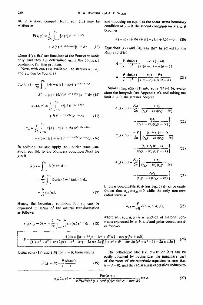
Substituting eqn (21) into eqns (14)+6); evalu- ating the integrals {see Appendix A), and taking the Iimit t- -+ 0, the stresses become
Xn polar coordinates R, (p (see Fig;, 2) it can be easily shown that Q+.+ = bRg = 0 while tbe only non-zero radial stress is
where F(u, b, c, d, I$) is a function of material con- stants expressed by a, b, c, d and polar coordinate 4 81 follows:
Using eqns (15) and (18) for y = 0, there results The orthotopic case (i.e. 0 = 0” or 90’) can be eiisily obtained by noting that thus imaginary part
P sin@C) sZ(A +sj=; - 0%
of the roots of characteristic equation is zero (i.e. f tr = d = 01, and the radi& stress expri&oB red- to
fl,(x,y)= --’ “’
Pm(a + c) ,’ sin I#I.
ZR(a’ sin2 4 + co2 #)(c2 sin2 +h + cof,+#) (27)
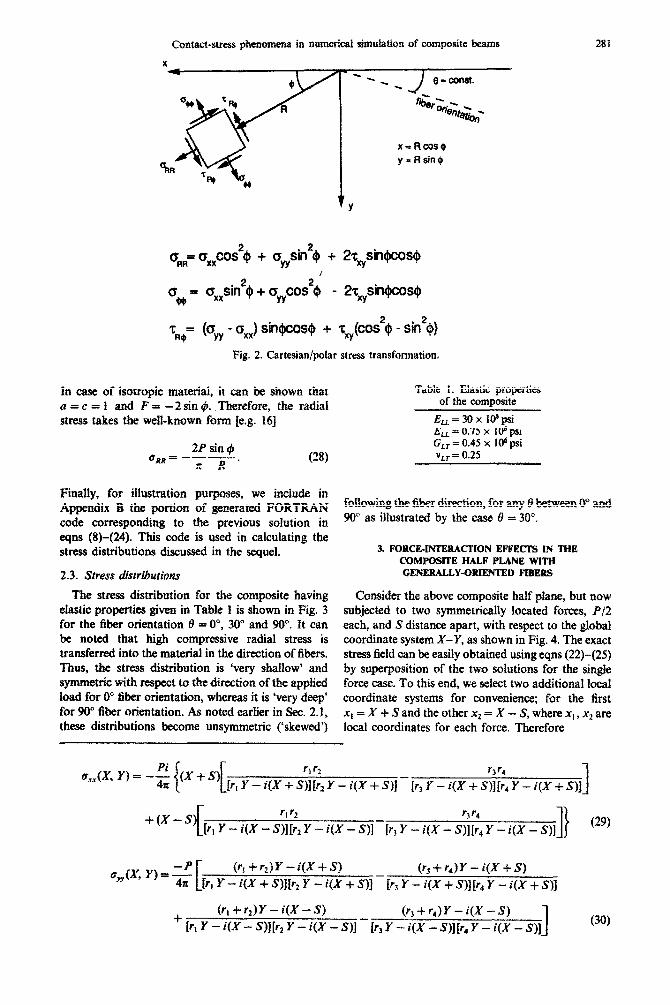
Contact-stress phenomena in numerical simulation of cmnposite beams 281
Fig. 2. Cartesian/polar stress transfomatian.
Ia case of isotropic material, it can be shown that a=c=f and F= -2 sin c#_ Therefore, the radial stress takes the we&known form [e.g. 151
2P sin C$I
unR= -n-’ Cw
R
Table 1. Elastic properties of the composite
.&=30x Wpsi ELL = 0.75 x ro* psi G,, = 0.45 x IO” psi Y LT = 0.25
Finahy, for ~ll~tra~on purposes, we include in Appendix B the pmkrn of generated FORTRAN fo~~o~g the fiber direction, for any i?I between 0” and
code corresponding to the previous solution in 90” as illustrated by the case 8 = JO”.
eqns (Q-(24). This code is used in calculating the stress distributians discussed in the sequel. 3. FORCEINTERACTION EFFECKS IN THE
CONPOSlTE HALF PLANE WITH
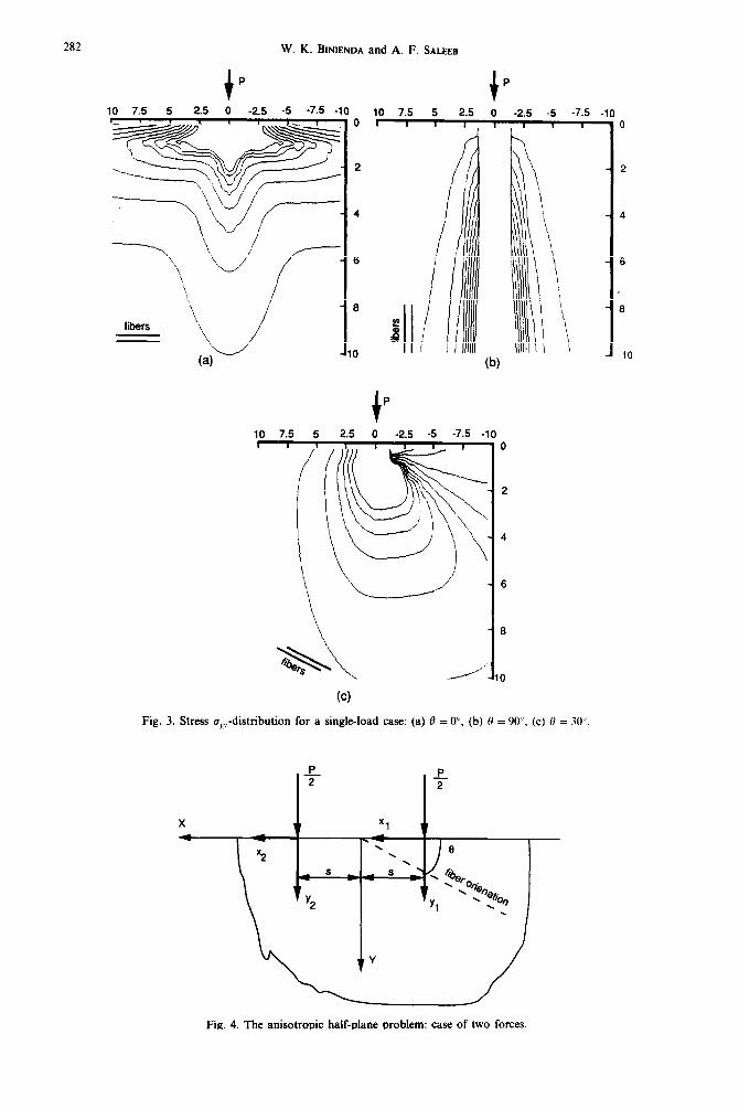
The stress distribution for the composite having Consider the above composite haif plane, but now eIa&c properties given in Table t is shown in Fig. 3 subjected to two symmetrically located forces, Pf2 for the fiber orientation 8 = O”, 30” and 90”. It can each, and S distance apart, with respect to the global be noted that high compressive radial stress is coordinate system X-Y, as shown in Fig. 4. The exact transferred into the material in the direction of fibers. stress field can be easily obtained using eqns (22)-(25) Thus, the stress distribution is ‘very shallow’ and by superposition of the two salutions for the single symmetric with respect to the direction of the appiied force case. To this end, we select two additional local Ioad for 0” fiber orientation, whereas it is *very deep’ coordinate systems for convenience; for the first for 90” fiber orientation. As noted earlier in Sec. 2.1, x, = X + Sand the other x2 = X - S, where x, , x2 are these distributions become unsymmetric (‘skewed’) local coordinates for each force. Therefore
a,fx, Y) = --p t
(rI -k r,)Y - i(X f S) (tj f r4)Y - iQ + S) 4~ @I Y - i(X + S)& Y - i(X + S)f - [r3 Y - i(X + SlIlra Y - i(X + 91
(x,+rz)Y-i(X-8) (r3 + r4) Y - i(X - S) + ir, Y - i(X - S)][r2 Y - i(X - S)] - [r3 Y - i(X - S)][r, Y - i(X - S)j 1 (30)
282 W. K. BINIENDA and A. F. SALEEB
P
10 7.5 5 2.5 0 -2.5 -5 -7.5 . I
fibers ’
.lO
I _ 1
0
2
4
6
8
d i 0
1 P
(W
Fig. 3. Stress a,,-distribution for a single-load case: (a) 0 = O”, (b) tI = 90”, (c) 0 = 30”
6
8
Fig. 4. The anisotropic half-plane problem: case of two forces

Contact-stress phenomena in numerical simulation of composite beams 283
rt r2 5 r4 Q (,y y,=-P’Y
.xy 3 4n 1 [r, Y - i(X + S)][rz Y - i(X + S)J - [r3 Y - i(X + Sll tr4 Y - i(X + S)l
+ [r, Y - i(X - S;ll;i2 Y - i(X - S)] - [r3 Y - i(X - S$Za Y - i(X - S)] > f (31)
The distribution of the stresses in this case is shown in Fig. 5. It is observed that, in addition to the significant influence of the fiber direction (as in the one force case), there is now some interaction between the two concentrated forces. Therefore, the distance parameter S may also be- important for the contact stress distribution, as is well illustrated by the series of curves representing normal stress at a constant distance yO = 5 and fiber direction 0 = 45” for different values of S in Fig. 6. The location of the maximum compressive con&t stresses is depicted
10 7.5 5 2.5 0 -2.5 -5 -7.5 -10
_ - fibers
t e
+ e
2 2
10 7.5 5 2.5 0 -2.5 -5 -7.E
iV”~
~~~ ~
x&h i
(c)
4
i 6
8
0
2
4
6
8
0
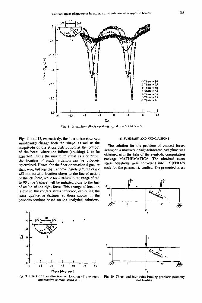
in Fig. 7 as a function of force distance S. From the series of curves representing normal stress a,,? distribution at a constant distance yO, and constant parameter S = 5 (Fig. 8), it can be noted that the m~imum negative stress is also a function of fiber direction. For example, the highest value of cry,, for @ = 30” is located close to the line of action of the right force, while for the fiber direction fI = 60” it is much closer to the left force (due to the interaction of the stresses generated by both forces). In Fig. 9 the location of the maximum compressive stress bY.” is
t
e. t
e 2 2
10 7.5 5 2.5 0 -2.5 -5 -7.5 -10
Fig. 5. Stress u,,y-distribution for two-loads case: (a) 0 = 0”, (b) 0 = 90”, (c) 0 = 30”, (d) 0 = 60”.

284 W. K. BINIENDA and A. F. SALEEB
-0.2 -
-0.4 -
.s b
0' -0.6 -
5 h G ODist. 2S = 14
-0.8 - ADist. 2s - 12 +Dist. 2S = 10 x Dist. 2s = 8 ODisr. 2s = 6 0 Dist. 2s = 4
-1.0 - *Dist. 2s = 2 2 Dis:. 2s = 1 Y Dist. 2S = 0
-1.2 I I I I I I 1 -16 -12 -8 4 0 4 8 I2
X/t
Fig. 6. Interaction effects on stress G,, at y = 5 and 0 = 45
shown as a function of the fiber direction 0. For the material properties used in the calculations (Table 1) and S = 5, this location changed from the left to the right line of action of the forces (from -5 to 5, respectively); it is close to zero for 0 = 45”.
4. CONTACT-STRESS PHENOMENA IN THREE AND FOUR-POINT BENDING OF COMPOSITE
BEAMS-FINITE ELEMENT SIMULATIONS
We consider here the analysis of a unidirectionally reinforced composite beam under the three or four- point bending conditions as shown in Fig. IO. The aspect ratio of the beam (i.e. length:height) is 4:l. Using finite element method (FEM), the location of
*r 6
4
< x
0
-2 1 I I I I I I I 0 1 2 3 4 5 6 7
S/t Fig. 7. Location of maximum compressive stress o,., vs
load-distance parameter S.
the crack initiation is investigated along the bottom of the beam. It is assumed that the crack will be initiated at a point where the stresses reach the strength of the material (i.e. the maximum stress criterion is often used). The calculations were con- ducted for the same composite material selected in the previous sections (elastic properties in Table 1). The emphasis here is placed on demonstrating that the same phenomenon observed in the rigorous sol- ution for the infinite anisotropic half plane, exists also in the finite domain for the generalized anisotropic case.
The finite element model utilized is a special two-dimensional (plane-stress) version of the general laminated shell element developed in [21,22]. It is a (four-noded) quadrilateral element of the hybrid/ mixed type; i.e. independent spatial discretizations are made for both displacement as well as strain fields within the element domain. Details of its formulation, together with a rather extensive set of test problems dealing with both isotropic and anisotropic struc- tures, are given in the above references, and further elaborations are omitted here.
For the present problem (Fig. IO), a rather ‘fine’ mesh of 10 x 80 elements is utilized in order to capture the desired details of the stress distributions (10 divisions in the direction of the beam depth and 80 divisions along its entire span). Stress results reported are taken from those at the integration (Gauss) points nearest to the lower surface (tension- side) of the beam.
As it can be noted from the series of curves for the three- and four-point bending cases shown in
Contact-stress phenomena in numerical simukxtion of compkte beams 285
-II I o Theta = 90 AThata = 1s + Theta = 60 I Theta t 45 0 Theta = 30 n l-hew - 15
0 4 Q Titetn = 0
I I I I I I 1 -16 -52 -8 -4 0 4 8 12
xn
Fig. 8. Interaction effects on stress s>,? at y = 5 and f = 5.
Figs 1 I and 12, rc?spectively, the fiber orientation can significantly change both the ‘shape’ as well as the magnitude of the stress ~~t~but~on at the bottom of the beam where the f&Sure (cracking) is to he expected. Using the maximum stress as a criterion, the location of crack initiation can be uniquely determined. Hence, for the fiber orientation 0 greater than zero, but less than approximately 30”, the crack will initiate at a location closer to the tine of actian of the left force, while for 3 values in the range of 30” to !W, the ‘failure* will be initiated close to the fine of action of the right force. This change of location is due to the ccmtact stress influence, exhibiting the same qualitative features as those shown in the previous sections based on the analytical solutions.
6r
-4 u
-6 T t f I f f 0 IS 30 45 60 75 90
Their [degrees]
Fig. 9. Effect of fiber direction on location of maximum compressive contact stress u~,,~.
5. SUMMARY AND CQNCLUSIONS
The soiution for the problem of contact forces acting on a u~idir~~ona~~y-rej~for~~ half plane was obtained with the help of the symbofic computation package MATHEMATICA. The obtained exact stress equations were converted into FORTRAN code for the parametric studies. The presented stress
tv
Fig- 10. Three- aad four-point beading problem: geometry and loading.

286 W. K. BINIENDA and A. F. SALEEB
_ d
4 g 0.4
“0 z 0
2 2 0.3
g z d3
2 0.2 I ” z 4 3 F 0.1 m f 3
2 0.0 0.0 5.0 10.0 15.0 20.0
Distance F’rom Left Support
Fig. 11. Maximum tensile stress o,, at bottom surface for the three-point bending problem
d) t’= 15.
/Ii e) e = 75.
e) .i ~.&, ; I’ ‘,,
//l/f’
\\.
\ !
\\ l\\ i \ \\
C.-l d .j 0.1 -
/-
\ ‘, \
3 /I ‘\\\ i : /’ ‘- \ \ z 5 0.0 ,.
0.0 5.0 10.0 15.0 20.0
Distance Ram Left Support
f) e = 30. g) 0 = 60.
Distance Ram Left Support
a) e=o. b) 0 = 45. c) 0 = 90.
n
3 ? E
2 0.0 ) 0.0 5.0 10.0 15.0 20.0
Distance Fhm Left Support
Fig. 12(a)-(c). Caprion opposite.
d) 8 = 15. e) 6 = 75.
Distance From Left Support
Fig. 12(d)-(e). Capfion opposite

Contact-stress phenomena in numerical simulation of composite beams 287
Distance From Left Support
Fig. 12(f)-(g)
h) 0 = 10. i) 0 = 60.
Diitance From Left support
Fig. 12(h)-(i)
Fig. 12. Maximum tensile stress u,, at bottom surface for the four-point bending problem.
distributions obtained for a graphite/epoxy com- posite, exhibited high dependency on fiber orien- tation. The case of two forces acting on the composite plane obtained using the exact stress equation, clearly demonstrated that both the fiber orientation as well as the spacing between the forces are important in redistributing the stress field. Such stress redistri- butions may influence the location of the crack initiation and the propagation of the crack.
The FEM simulations of the three- and four-point bending tests has also confirmed the same qualitative dependence of the stress distribution on the fiber orientation in the more practical, finite-length, beam case. An important conclusion immediately follows from these results; i.e. the crack initiation and poss- ibly its subsequent propagation can be controlled by the fiber orientation in the beam. However, further studies on this latter subject of the matrix crack propagation in the beam under three- and four-point bending conditions have to be conducted. This is particularly true in view of the far complex nature of the stress distribution in the contact regions at the reactions (e.g. depending on the type of the support mechanisms utilized). These studies are planned for a future publication.
The presented analysis explains the influence of the contact stresses that cannot be disregarded in the tlexural testing of the composite. Indeed, better understanding of this influence may then lead to more rational predictions for strength of the com- posite material and the subsequent ‘fracture-type’ analysis in the form of matrix crack-propagation in the beam.
REFERENCES 15. i’ W. Orange, -Stress intensity and crack displace-
ment for small edge crack. NASA technical paper 2801 (1988).
1. C. 0. Hogan, On Saint-Venant’s principle in plane anisotropic elasticity. J. Ektsticity 2, 169-180 (1972).
16. S. Timoshenko and J. N. Goodier, Theory of Elasticity, 2nd Edn. Chap. 4. McGraw-Hill.
2. G. C. Everstine and A. C. Pipkin, Stress channelling in transversely isotropic elastic composites. 1. uppl. Math. Phvs. (ZAMP) 22. 825-834 (1971).
3. J. M. Whitney, Elasticity.analysis of orthotopic beams under concentrated loads. Cotnpos. Sri. Technol. 22, 167-183 (1985).
4. J. M. Whitney and C. E. Browning, On short-beam shear tests for composite materials. Exper. Mech. 25, 294-300 (1985).
5. J. M. Whitney and C. E. Browning, Materials character- ization for matrix dominated failure modes. In Eficts of Defects in Comtwsite Materials. ASTM STP 836 (edited by D. J. Wilkins), pp. 104i24 (1984).
6. C. E. Browning, F. L. Abrams and J. M. Whitney, A four-point shear test for graphite/epoxy composites. In Composite Materials: Quality Assurance and Pro- cessing, ASTM STP 797 (Edited by C. E. Browning), pp. 54-74, 1983.
7. P. E. Sandorff, Saint-Venant effects in an orthotopic beam. J. Compo. Muter. 14, 199-212 (1980).
8. R. G. C. Arridge, P. C. Barham, C. G. Farrell and A. Keller, The importance of end effects in the measurement of moduli of highly anisotropic materials. J. Mater. Sci. 11, 778-790 (1976).
9. C. T. Sun and S. Chattopadhyay, Dynamic response of anisotropic laminated plates under initial stress to impact. J. appi. Mech., ASME 42, 693-698 (1975).
10. W. Elber, Failure mechanics in low-velocity impacts on thin composite plates. NASA TP-2152 (1983):
1 I. C. T. Sun and B. V. Sankar. Smooth indentation of an initially stressed orthotopic beam. Inf. J. Solid Sfruct. 21, 161-176 (1985).
12. L. M. Keer and R. Ballarini, Smooth contact between a rigid indenter and an initially stressed orthotopic beam. AIAA JI 21, 1035-1042 (1983).
13. B. V. Sankar, An approximate Green’s function for beams and application to contact problems. J. Appl. Mech., ASME, to be published.
14. B. V. Sankar, Contact stresses in an orthotopic beam. In Proceedings of the American Society for CGmposites, PP. 489-499, Sept. (1987).
288 W. K. EMENDA and A. F. SAL.EEB
17.
18.
19.
20.
21.
22.
S. G. Lekhnitskii, Anis~~ropic Plates, Chap. 4. Gordon and Breach, (1968). A. E. Green and W. Zerna, Theorehcal Elasticity. 2nd Edn. Clarendon Press, Oxford (1968). J. Boussinesq, Appljcations des Potentials a l’etude de l’equilibre et due mouvement des solids elastique. Guathier-Vailars Paris (1985). I. S. Gradshetyn and f. M. Ryzhik, Tables o~~nfe~pais, Series and Producu. Academic Press (1980). A. F. Saleeb, T. Y. Chang and W. Graf, A quadrilateral shell element using a mixed formulation. Compur. Srruct. 26, 787-803 (1987). T. Wilt, A. F. Saleeb and T. Y. Chang, A mixed element for laminated plates and shells. Camput. Struct. 37, 597-61 I (1990).
APPENDIX A: STRE!%EQUATION INTEGRATION
Substituting eqn (21) into eqn (15), taking the integration interval from --co to 0 (Is/= -s) and from 0 to 03 ({sl=s), we obtain
-(--a~jb)e”‘-“+‘at’+‘risJds (Ai)
Then, by replacing appropriately the dummy variable s by --s and changing the integration order in the first
term making it from 0 to -t-m the above Fig. (AI) becomes
W)
which can be expressed as a sum of four integrals of the following form
1, - 1
z sin i -7 exp[-p,j]di for k = 1,2,3,4, (A3) 11
where [ = ts and p& = U& (for example for k = I, u1 =i {(a + ib)y - ix]). The result in eqn (A3) can be found in tables of integral (201 as
(A4)
For concentrated force case, the limit of eqn (A4) has to be taken (i.e. t -) 0). To this end, the CHopit& rule must be applied, leading finally to the stress equation in the following form
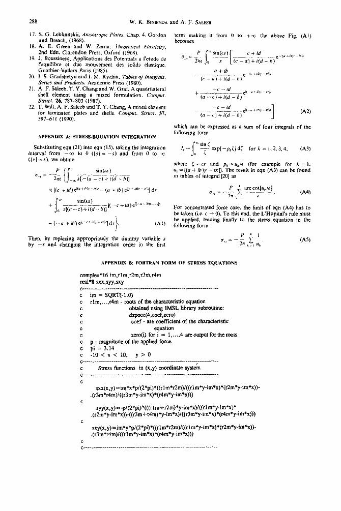
APPENDIX 8: FORTRAN FORM OF STRESS EQUATIONS
complex*16 im,rlm,r2m,r3m,r4m real?3 sxx,syy,sxy c__________-_____________-____________________-*__-“-_________----_--_-
C im = SQRT(-1.0) c rlm , . . . ,r4m - roots of the characteristic equation c obtained using IMSL Iibraxy sub~utine~ C dzpocc%oef,~M C coef - are coefficient of the characteristic c equation c zero(i) for i 5 I,...,4 ~ou~utfar~cr~~ c p - magnitude of the applied force c pi=3.14 C -10 < x < 10, y > 0 C__________________________________ ________“____” ___________r_____.._I”_
C Stress functions in (x,y) coordinate systeh c__.._________-______--___-____ ____ _____________ -__--. ______ --_- ----.....
C sxx(x,y)~im*x*p/(2*pi)*((rlm*r2m)/((rlm*y-im*x)*{rZm*y-im*x))-
.(~m*r4m)/((r3m*y-im*x)*(r4m*y-im*x~~) c
syy(x,y)“-pi(2*pi)*(((rlm+~m)*y-im*x)l(* .(rZm*y-im*x))-((r3m+r4m)*y-im*x)/((r3m*y-im*x)*(r4m*y-im*x)))
C sxy(x,y)=im*y*p/(Z*pi)*((rlm*Pr2m)f((rIm*y-im*x)*(r2m*y-im*x))-
.(r3m*r4m)/{(r3m*y-im*x)*(r4m*y-im*x))) C C______________________-____________________________.______________*___
(A%