Embed Size (px)
Citation preview

Consumer OASIS User Guide
1040630-0001
Revision E
April 25, 2017
11717 Exploration Lane, Germantown, MD 20876
Phone (301) 428-5500 Fax (301) 428-1868/2830

Copyright © 2015-2017 Hughes Network Systems, LLC
All rights reserved. This publication and its contents are proprietary to Hughes Network Systems, LLC. No part of this publication may be reproduced in any form or by any means without the written permission of Hughes Network Systems, LLC, 11717 Exploration Lane, Germantown, Maryland 20876.
Hughes Network Systems, LLC has made every effort to ensure the correctness and completeness of the material in this document. Hughes Network Systems, LLC shall not be liable for errors contained herein. The information in this document is subject to change without notice. Hughes Network Systems, LLC makes no warranty of any kind with regard to this material, including, but not limited to, the implied warranties of merchantability and fitness for a particular purpose.
Trademarks
HUGHES and Hughes Network Systems are trademarks of Hughes Network Systems, LLC. All other trademarks are the property of their respective owners.
Contents
1040630-0001 Revision E 3
Contents Chapter 1 Introduction ........................................................................................... 5 Scope and audience ............................................................................................... 5 Overview ................................................................................................................ 5 Installing OASIS ...................................................................................................... 5 Launching and logging into OASIS daily ................................................................. 6
OASIS homepage .............................................................................................. 8 Beginning an install .............................................................................................. 10 Step progression .................................................................................................. 11 Backing up attachments ...................................................................................... 13 Troubleshooting ................................................................................................... 14
Chapter 2 Arriving at the site ................................................................................ 15 Performing an indoor site survey ........................................................................ 15 Performing an outdoor site survey ...................................................................... 15 Arrival step ........................................................................................................... 16 Sat Info step ......................................................................................................... 19 Line of Sight step .................................................................................................. 20 Pre Sign step ........................................................................................................ 22 Barcode step ........................................................................................................ 24 Establishing a connection to the modem ............................................................ 26
Configuring your own wireless router ............................................................ 26 Using your wireless router to connect to the modem ................................... 27 Connecting to the HT2000W’s built-in router ................................................ 28
WIFI/IDU step ...................................................................................................... 29 Wi-Fi Gauge step .................................................................................................. 31 Sat Info step ......................................................................................................... 33
Chapter 3 Pointing the antenna ............................................................................ 37 Antenna installation ............................................................................................. 37 Pointing step ........................................................................................................ 38
Chapter 4 Registering and activating the modem ................................................ 41 OVT step ............................................................................................................... 43 Activate step ........................................................................................................ 47
Chapter 5 Taking photos ....................................................................................... 49 Photos step .......................................................................................................... 49

4 Contents
1040630-0001 Revision E
Chapter 6 Departing from the site ........................................................................ 51 Activating the customer’s service ........................................................................ 51 Accept step .......................................................................................................... 51 Depart step .......................................................................................................... 54 FSO Step Summary page ...................................................................................... 56 Verify data upload ............................................................................................... 57 Delete local files ................................................................................................... 61
Appendix A Performing repair orders ...................................................................... 63 Diagnosis step ...................................................................................................... 63 IDU Swap step ...................................................................................................... 64 Departure resolution codes ................................................................................. 65
Appendix B Troubleshooting.................................................................................... 69 Software updates ................................................................................................. 69 FAQs ..................................................................................................................... 69
Index .................................................................................................... 73
Chapter 1 • Introduction
1040630-0001 Revision E 5
Chapter 1
Introduction
Scope and audience This document explains how to use the Onsite Accelerated Service Installation System (OASIS) app when performing a Consumer installation. It is written for professional installers who use the app on their smart device to facilitate their duties during a site visit.
Installers should reference this document whenever they need additional guidance.
Overview The OASIS app is designed for use with smart devices (e.g., tablets and smart phones). It provides a step-by-step process for the installer to follow from site arrival to site departure.
This guide is best read from beginning to end. It follows the flow of the app and the chronology of the installation process.
Installing OASIS OASIS is available as a download from the Hughes Appstore (http:\\appstore.hughes.com); you cannot download this app from the Apple App Store or the Google Play store. You must download this app from the mobile browser of a smart device (i.e., not from a computer).
Notes:
Make sure you delete any previous versions of the app from your device before installing a new version.
The app consumes approximately 15 MB of space in Apple iOS and 12 MB of space in Google Android, but Hughes recommends your device has at least 100 MB of free space to accommodate the photos you will take during your installations.
For Android devices, check your settings to make sure apps from unknown sources are allowed.
For iOS devices, check your Device Management settings to make sure Hughes Network Systems is listed as a trusted source.
Before you install a software update for your smart device, uninstall OASIS. Once you have applied the software update, download and reinstall the latest version of OASIS from the Installation Portal.
In order for OASIS to work correctly, you must have GPS location services enabled on your smart device. Consult your smart device’s documentation for instructions on how to enable this.
6 Chapter 1 • Introduction
1040630-0001 Revision E
Launching and logging into OASIS daily Before you depart for any installation, your must connect your smart device to the Internet and log into OASIS so the app can verify your installer account, synchronize your field service orders (FSOs), and download the latest SBC file. If you do not sync your device daily, you may not have latest SBC file, which will prevent you from getting a high enough signal quality factor (SQF) to complete the installation.
Note: While you need Internet access for initial syncing, you will not need Internet access while you are performing the installation.
To log into OASIS and sync your device:
1. Ensure your device is connected to the Internet. 2. Tap the OASIS icon to launch the app. A splash page displays for a few seconds
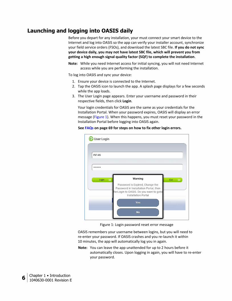
while the app loads. 3. The User Login page appears. Enter your username and password in their
respective fields, then click Login.
Your login credentials for OASIS are the same as your credentials for the Installation Portal. When your password expires, OASIS will display an error message (Figure 1). When this happens, you must reset your password in the Installation Portal before logging into OASIS again.
See FAQs on page 69 for steps on how to fix other login errors.
Figure 1: Login password reset error message
OASIS remembers your username between logins, but you will need to re-enter your password. If OASIS crashes and you re-launch it within 10 minutes, the app will automatically log you in again.
Note: You can leave the app unattended for up to 2 hours before it automatically closes. Upon logging in again, you will have to re-enter your password.
Chapter 1 • Introduction
1040630-0001 Revision E 7
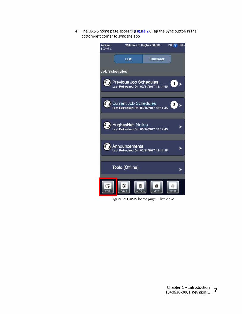
4. The OASIS home page appears (Figure 2). Tap the Sync button in the bottom-left corner to sync the app.
Figure 2: OASIS homepage – list view
8 Chapter 1 • Introduction
1040630-0001 Revision E
OASIS homepage
The OASIS homepage (Figure 2 on page 7) contains menus for previous jobs, current jobs, current HughesNet notes, announcements, and offline tools. Tap a menu to expand it. Tap the refresh icon ( ) to refresh a specific menu. The contents of each menu are explained below.
Previous Job Schedules – Shows jobs you missed, as well as jobs you completed but have yet to post to the Installation Portal.
Current Job Schedules – Shows current and future jobs, and provides maps and directions to the job location.
HughesNet Notes – Shows current news pertaining to HughesNet. Identical to the HughesNet notes on the Installation Portal.
Announcements – Shows current news pertaining to HughesNet and OASIS. Identical to the announcements on the Installation Portal.
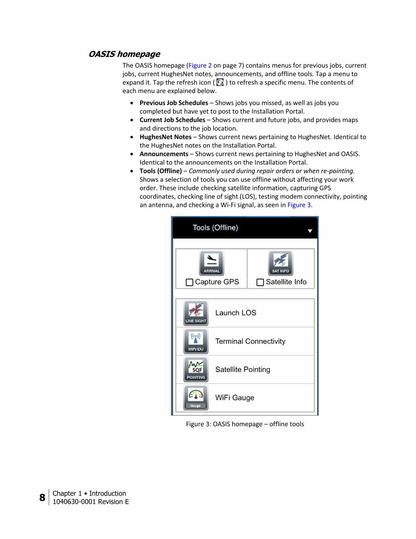
Tools (Offline) – Commonly used during repair orders or when re-pointing. Shows a selection of tools you can use offline without affecting your work order. These include checking satellite information, capturing GPS coordinates, checking line of sight (LOS), testing modem connectivity, pointing an antenna, and checking a Wi-Fi signal, as seen in Figure 3.
Figure 3: OASIS homepage – offline tools
Chapter 1 • Introduction
1040630-0001 Revision E 9
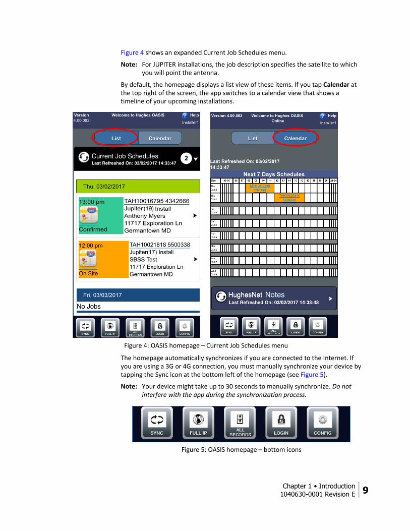
Figure 4 shows an expanded Current Job Schedules menu.
Note: For JUPITER installations, the job description specifies the satellite to which you will point the antenna.
By default, the homepage displays a list view of these items. If you tap Calendar at the top right of the screen, the app switches to a calendar view that shows a timeline of your upcoming installations.
Figure 4: OASIS homepage – Current Job Schedules menu
The homepage automatically synchronizes if you are connected to the Internet. If you are using a 3G or 4G connection, you must manually synchronize your device by tapping the Sync icon at the bottom left of the homepage (see Figure 5).
Note: Your device might take up to 30 seconds to manually synchronize. Do not interfere with the app during the synchronization process.
Figure 5: OASIS homepage – bottom icons
10 Chapter 1 • Introduction
1040630-0001 Revision E
The rest of the icons in Figure 5 perform the following actions.
Full IP – Opens the Installation Portal. All Records – Shows your work submission status. Login – Takes you back to the login page, where you can log out of the app.
You can also use this to change your password if you already changed it in the Installation Portal.
Config – Shows user configuration options. For example, you can change how often the app synchronizes and how many days are shown in your schedule.
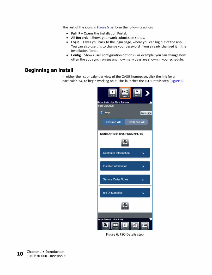
Beginning an install In either the list or calendar view of the OASIS homepage, click the link for a particular FSO to begin working on it. This launches the FSO Details step (Figure 6).
Figure 6: FSO Details step
Chapter 1 • Introduction
1040630-0001 Revision E 11
This step contains all the pertinent information about your currently selected job. The information contained in this step is the same information you would see on your installation reference sheet (IRS).
Tap a menu to expand it. Tap Expand All or Collapse All to open or close every menu at once. The menus include:
Customer Information – Shows the customer name, address, phone number, PIN, SAN, etc.
Installer Information – Shows the dealer name, phone number, email, etc. Service Order Notes – Shows the satellite at which you will point, the plan the
customer is receiving, the radio polarization you should use, etc. Always make sure the radio polarization shown in the service order notes is the polarization you use for the installation.
Bill Of Materials – Shows what equipment you should bring to the installation.
Step progression You should always tap the Next button ( ) to proceed to the next step if you are following the step-by-step OASIS sequence. For example, once you have completed reviewing the details of your FSO in the FSO Details step, you should tap Next to proceed to the Arrival step – the next step in the OASIS sequence.
Note: The Next button will not appear until you have completed the step.
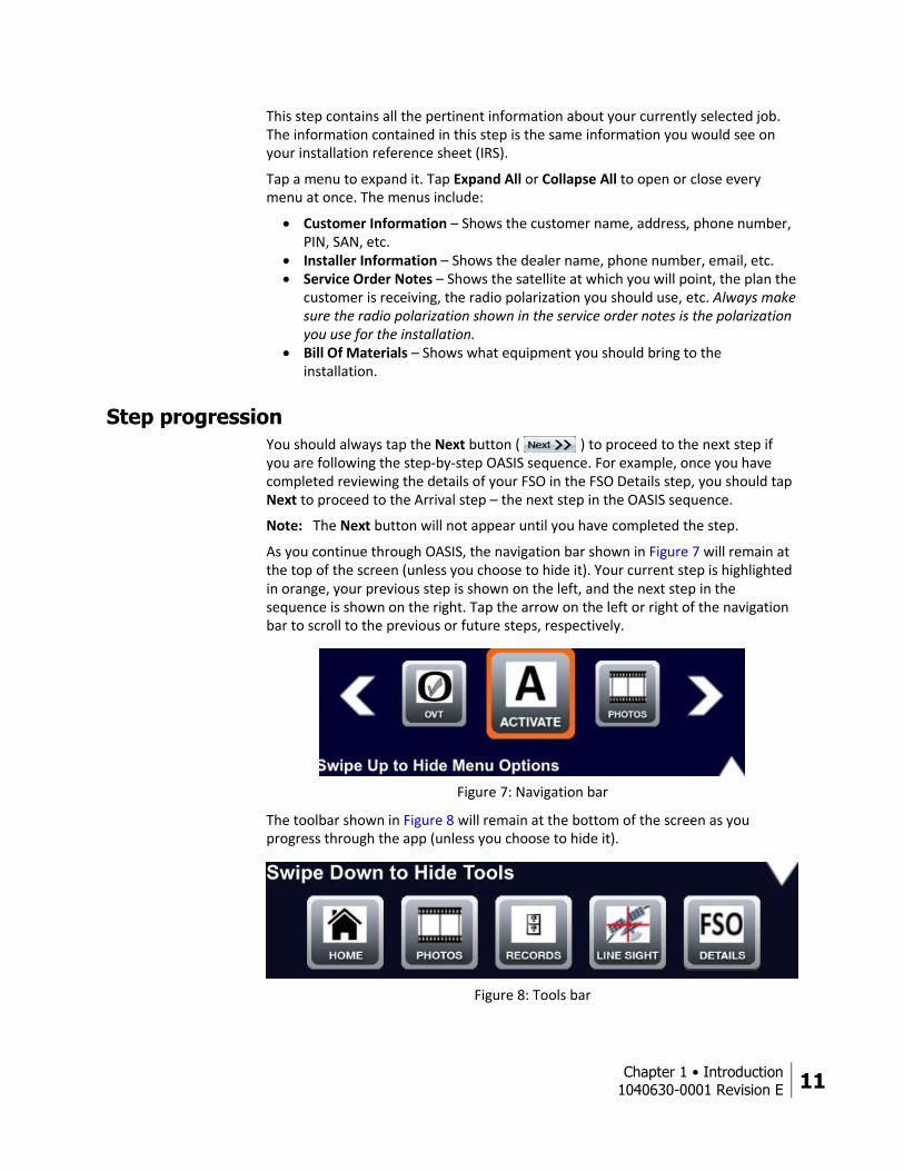
As you continue through OASIS, the navigation bar shown in Figure 7 will remain at the top of the screen (unless you choose to hide it). Your current step is highlighted in orange, your previous step is shown on the left, and the next step in the sequence is shown on the right. Tap the arrow on the left or right of the navigation bar to scroll to the previous or future steps, respectively.
Figure 7: Navigation bar
The toolbar shown in Figure 8 will remain at the bottom of the screen as you progress through the app (unless you choose to hide it).
Figure 8: Tools bar
12 Chapter 1 • Introduction
1040630-0001 Revision E
Tapping an icon does the following.
Home – Navigates back to the OASIS homepage and syncs any orders you have if you are connected to the Internet.
Photos – Navigates to the Photos step, allowing you to take a photo before returning back to step you were completing.
Records – Shows the status of completed steps in your current work order. Also shows information about completed orders.
Line Sight – Navigates to the Line of Sight step, which allows you to check LOS with the satellite before returning to the step you were completing.
FSO Details – Navigates to the FSO Details step.
All steps in OASIS have a built-in help menu. Tap the help icon ( ) to access this menu.
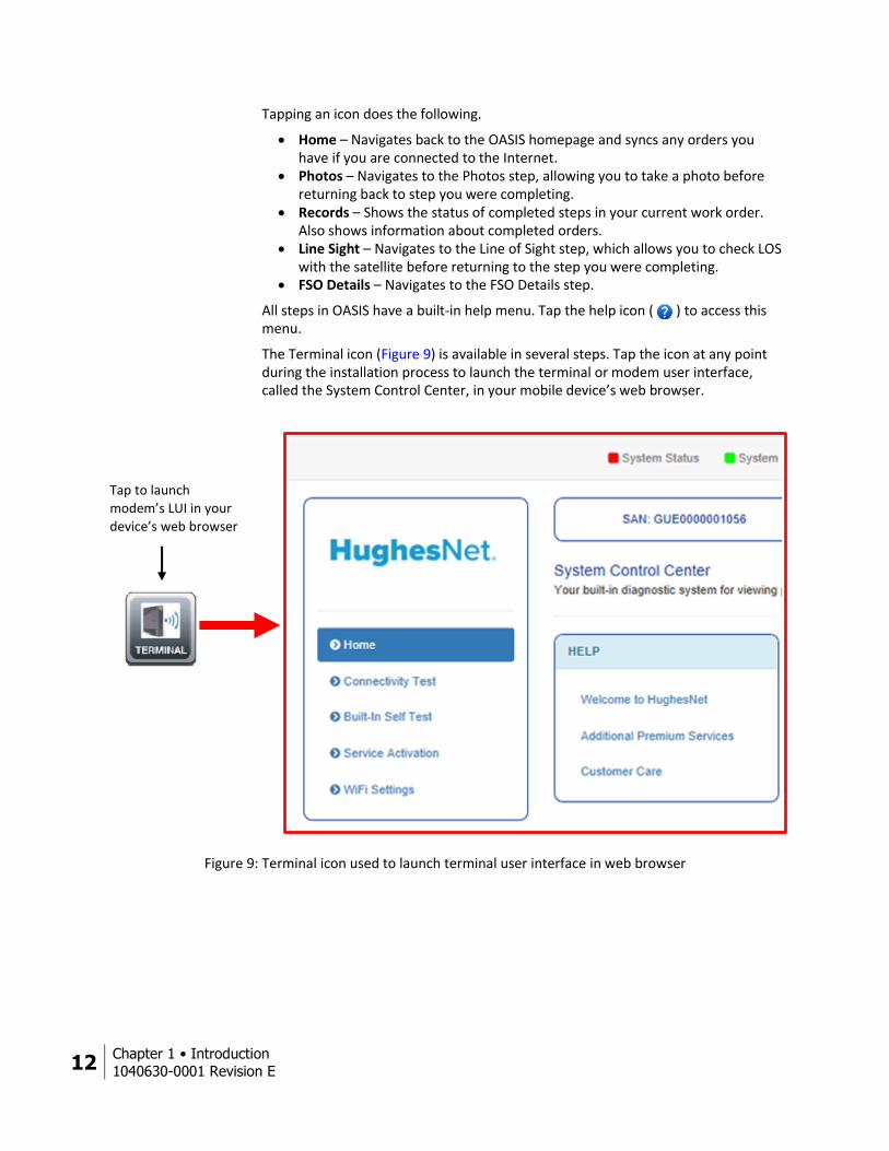
The Terminal icon (Figure 9) is available in several steps. Tap the icon at any point during the installation process to launch the terminal or modem user interface, called the System Control Center, in your mobile device’s web browser.
Figure 9: Terminal icon used to launch terminal user interface in web browser
Tap to launch
modem’s LUI in your
device’s web browser
Chapter 1 • Introduction
1040630-0001 Revision E 13
Backing up attachments At any point during the installation, you can back up any attachments you have (i.e., pictures and signatures). This prevents data loss in the event of an app crash; or, if you do not have Internet access to upload the attachments to the Installation Portal at the end of an installation, this allows you to save the attachments and upload them at a later time when you have a better connection.
To export your attachments to the photo gallery on your smart device:
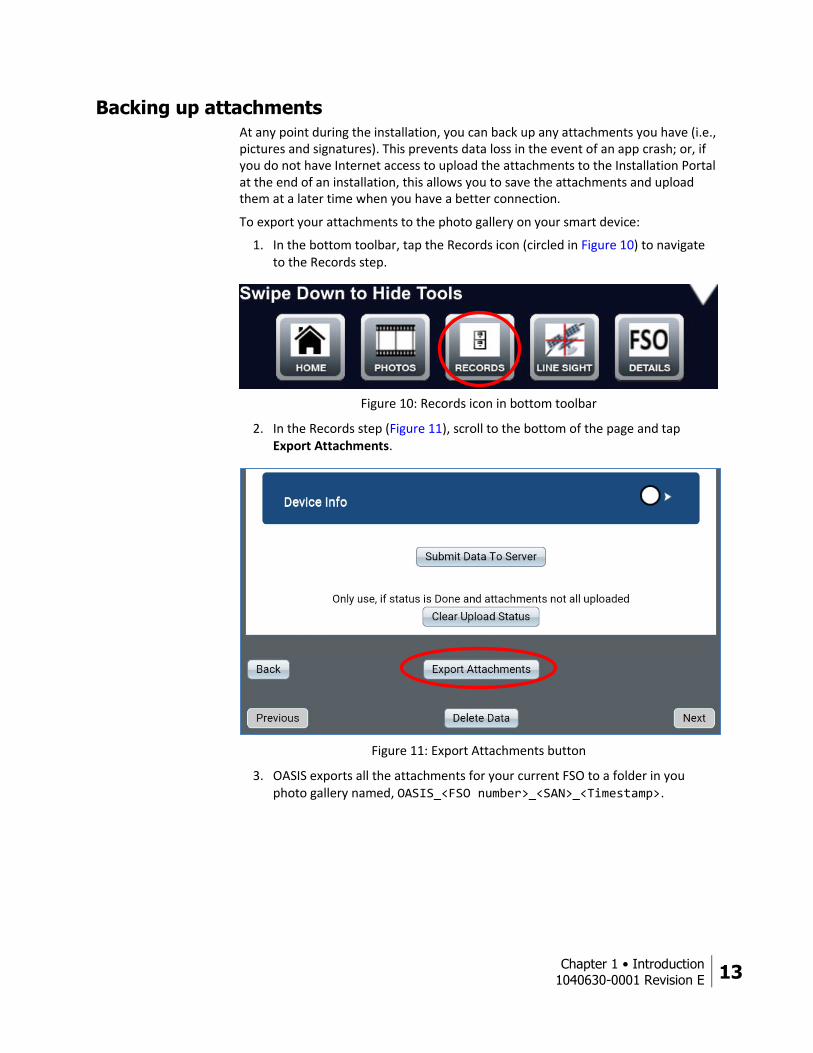
1. In the bottom toolbar, tap the Records icon (circled in Figure 10) to navigate to the Records step.
Figure 10: Records icon in bottom toolbar
2. In the Records step (Figure 11), scroll to the bottom of the page and tap Export Attachments.
Figure 11: Export Attachments button
3. OASIS exports all the attachments for your current FSO to a folder in you photo gallery named, OASIS_<FSO number>_<SAN>_<Timestamp>.
14 Chapter 1 • Introduction
1040630-0001 Revision E
Troubleshooting Before contacting Hughes, read the troubleshooting information in Appendix B – Troubleshooting on page 69. If the solution to your problem is not given there, call Hughes Installer Support at 1-866-259-9444
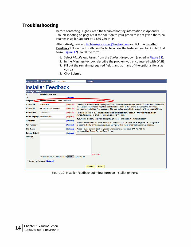
Alternatively, contact [email protected] or click the Installer Feedback link on the Installation Portal to access the Installer Feedback submittal form (Figure 12). To fill the form:
1. Select Mobile App Issues from the Subject drop-down (circled in Figure 12). 2. In the Message textbox, describe the problem you encountered with OASIS. 3. Fill out the remaining required fields, and as many of the optional fields as
you can. 4. Click Submit.
Figure 12: Installer Feedback submittal form on Installation Portal
Chapter 2 • Arriving at the site
1040630-0001 Revision E 15
Chapter 2
Arriving at the site When you arrive at the installation site, introduce yourself to the customer and explain to them how you will progress through the installation. Thoroughly answer all of the customer’s questions.
Performing an indoor site survey Before you perform an outdoor site survey to find a good location for the antenna, you must perform an indoor site survey to determine a good location for the modem. The following steps explain this process for an HT2000W. These steps will differ for other modems.
1. Ask the customer where they would like the HT2000W placed, and accommodate their request the best you can.
2. Plug in and power on the modem. Be sure to test the outlet before you plug the modem into it.
3. Use your smart device to connect to the HT2000W’s wireless network. This process is explained in Connecting to the HT2000W’s built-in router on page 28.
4. You must now test the HT2000W’s wireless signal around the customer’s house. First, ask the customer for permission to walk around the inside of their house to test the wireless signal in several rooms.
Next, use the Wi-Fi gauge in OASIS to measure the wireless signal in multiple rooms. See Wi-Fi Gauge step on page 31 for an explanation of how to use the tool. Use the arrows in the top navigation bar in OASIS to move forward to the Wi-Fi Gauge step. When you are done, move back to the beginning of the OASIS workflow.
5. Based on the test results, determine if the HT2000W can provide good wireless coverage to the customer’s house from its current location. If it cannot, offer to move the modem to a different location, or, if the customer prefers, they may purchase a Hughes Wi-Fi Booster to extend the HT2000W’s wireless signal.
If the customer chooses to purchase a Booster, you must itemize the purchase as described in Pre Sign step on page 22.
Performing an outdoor site survey Once the customer agrees to the modem placement location, begin an outdoor site survey to determine the location for the antenna. Use the information provided in the appropriate site preparation and mount installation guide, depending on the type of installation you are performing. Make sure the customer approves of your chosen antenna location.
If you discuss any installation extras with the customer during the outdoor site survey, be sure to itemize those extras as described in Pre Sign step on page 22
16 Chapter 2 • Arriving at the site
1040630-0001 Revision E
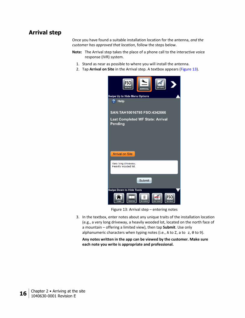
Arrival step Once you have found a suitable installation location for the antenna, and the customer has approved that location, follow the steps below.
Note: The Arrival step takes the place of a phone call to the interactive voice response (IVR) system.
1. Stand as near as possible to where you will install the antenna. 2. Tap Arrival on Site in the Arrival step. A textbox appears (Figure 13).
Figure 13: Arrival step – entering notes
3. In the textbox, enter notes about any unique traits of the installation location (e.g., a very long driveway, a heavily wooded lot, located on the north face of a mountain – offering a limited view), then tap Submit. Use only alphanumeric characters when typing notes (i.e., A to Z, a to z, 0 to 9).
Any notes written in the app can be viewed by the customer. Make sure each note you write is appropriate and professional.
Chapter 2 • Arriving at the site
1040630-0001 Revision E 17
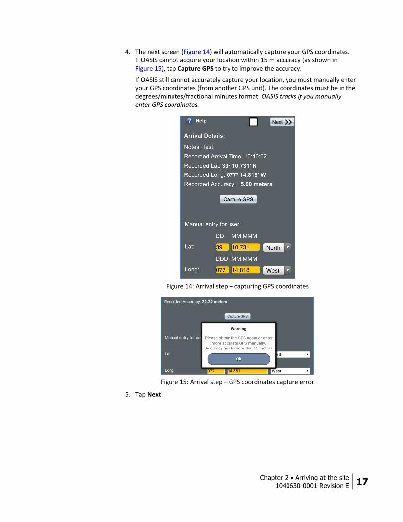
4. The next screen (Figure 14) will automatically capture your GPS coordinates. If OASIS cannot acquire your location within 15 m accuracy (as shown in Figure 15), tap Capture GPS to try to improve the accuracy.
If OASIS still cannot accurately capture your location, you must manually enter your GPS coordinates (from another GPS unit). The coordinates must be in the degrees/minutes/fractional minutes format. OASIS tracks if you manually enter GPS coordinates.
Figure 14: Arrival step – capturing GPS coordinates
Figure 15: Arrival step – GPS coordinates capture error
5. Tap Next.

18 Chapter 2 • Arriving at the site
1040630-0001 Revision E
6. A verification pop-up message appears (Figure 16). Verify the customer information it shows, then tap Yes to proceed to the next step – Sat Info.
Note: Pay close attention to the arrival on site distance measurement. If OASIS shows your location as very far away from the installation location, make sure you are at the correct address for the installation.
Figure 16: Arrival step – verification
Chapter 2 • Arriving at the site
1040630-0001 Revision E 19
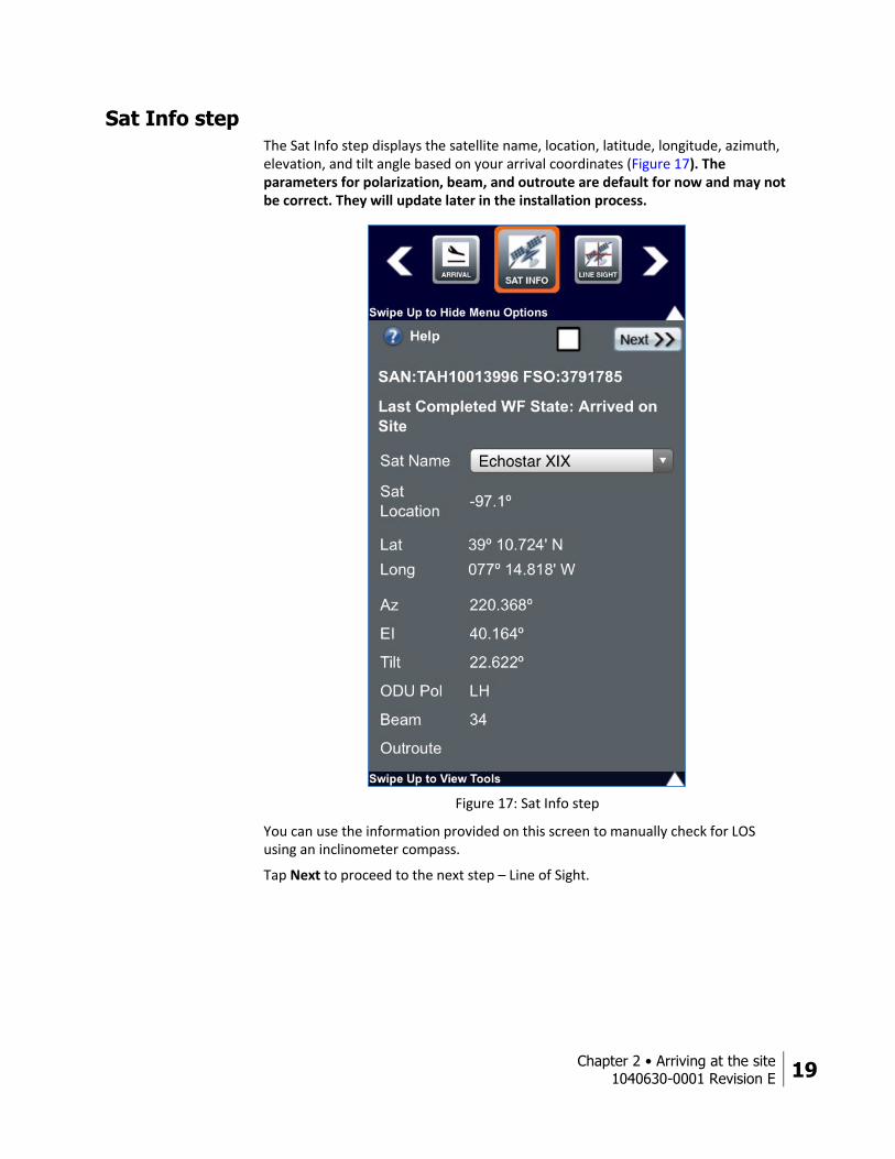
Sat Info step The Sat Info step displays the satellite name, location, latitude, longitude, azimuth, elevation, and tilt angle based on your arrival coordinates (Figure 17). The parameters for polarization, beam, and outroute are default for now and may not be correct. They will update later in the installation process.
Figure 17: Sat Info step
You can use the information provided on this screen to manually check for LOS using an inclinometer compass.
Tap Next to proceed to the next step – Line of Sight.
20 Chapter 2 • Arriving at the site
1040630-0001 Revision E
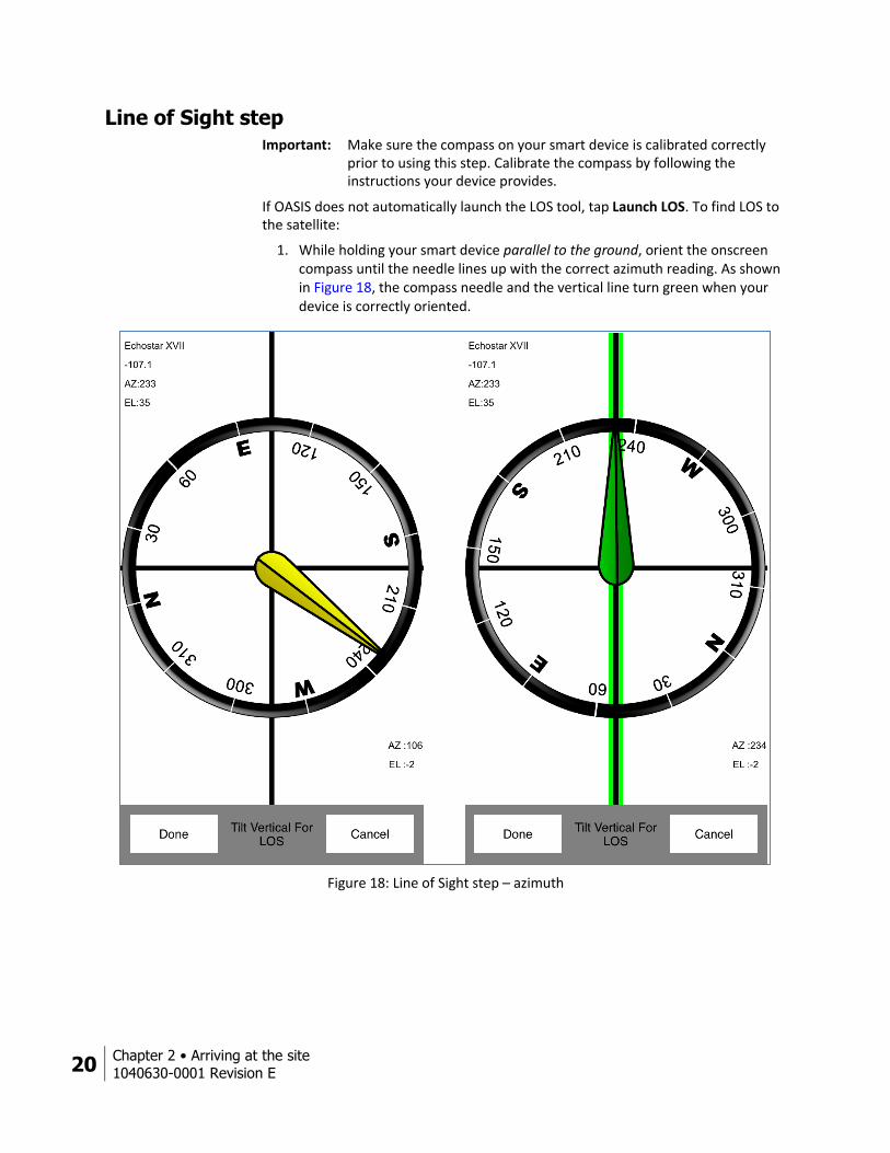
Line of Sight step Important: Make sure the compass on your smart device is calibrated correctly
prior to using this step. Calibrate the compass by following the instructions your device provides.
If OASIS does not automatically launch the LOS tool, tap Launch LOS. To find LOS to the satellite:
1. While holding your smart device parallel to the ground, orient the onscreen compass until the needle lines up with the correct azimuth reading. As shown in Figure 18, the compass needle and the vertical line turn green when your device is correctly oriented.
Figure 18: Line of Sight step – azimuth

Chapter 2 • Arriving at the site
1040630-0001 Revision E 21
2. Tilt your device vertically to launch the LOS feature, which is shown in Figure 19.
3. Maneuver your smart device until the red crosshair (which represents the direction you are currently pointing) lines up with the yellow crosshair (which represents the location of the satellite).
The yellow crosshair will turn green when you are within 5 degrees of exact alignment with the satellite, as shown in Figure 19.
4. Make sure nothing blocks the LOS. The LOS must be free of obstructions, such as plants, trees, buildings, or other structures.
Examine nearby plants and trees and consider how they might grow and eventually block the signal. If you perform the installation during the fall or winter, consider spring and summer leaf growth.
Ask the customer if they have any plans (such as landscaping) that might obstruct the satellite signal at some time in the future.
If anything blocks the LOS, you must find another installation location.
Figure 19: Line of Sight step – elevation
5. Tap Capture (circled in Figure 19) to take a screenshot of the LOS measurements. OASIS records the required LOS information (satellite name, satellite location, and Az/El measurements).
Note: This is a site assessment tool only. The photo you take here does not count as the required LOS photo.
6. Tap Next to proceed to the next step – Pre Sign.

22 Chapter 2 • Arriving at the site
1040630-0001 Revision E
Pre Sign step The Pre Sign step (Figure 20) coincides with the site survey review you must perform with the customer. During the review, tell the customer about the dish location you have chosen, the type of mount you will use, and any additional charges (e.g., wireless routers, cosmetic moldings, the Hughes Wi-Fi Booster).
Figure 20: Pre Sign step
Once you have the customer’s approval, proceed with the Pre Sign step:
1. Select the type of antenna mount from the Mount Type drop-down. 2. Select the location of the antenna from the Dish Location drop-down. 3. Enter the serial number and MAC address of the wireless router you are
installing for the customer, if it is a separate wireless router (i.e., not the HT2000W’s built-in wireless router).
Chapter 2 • Arriving at the site
1040630-0001 Revision E 23
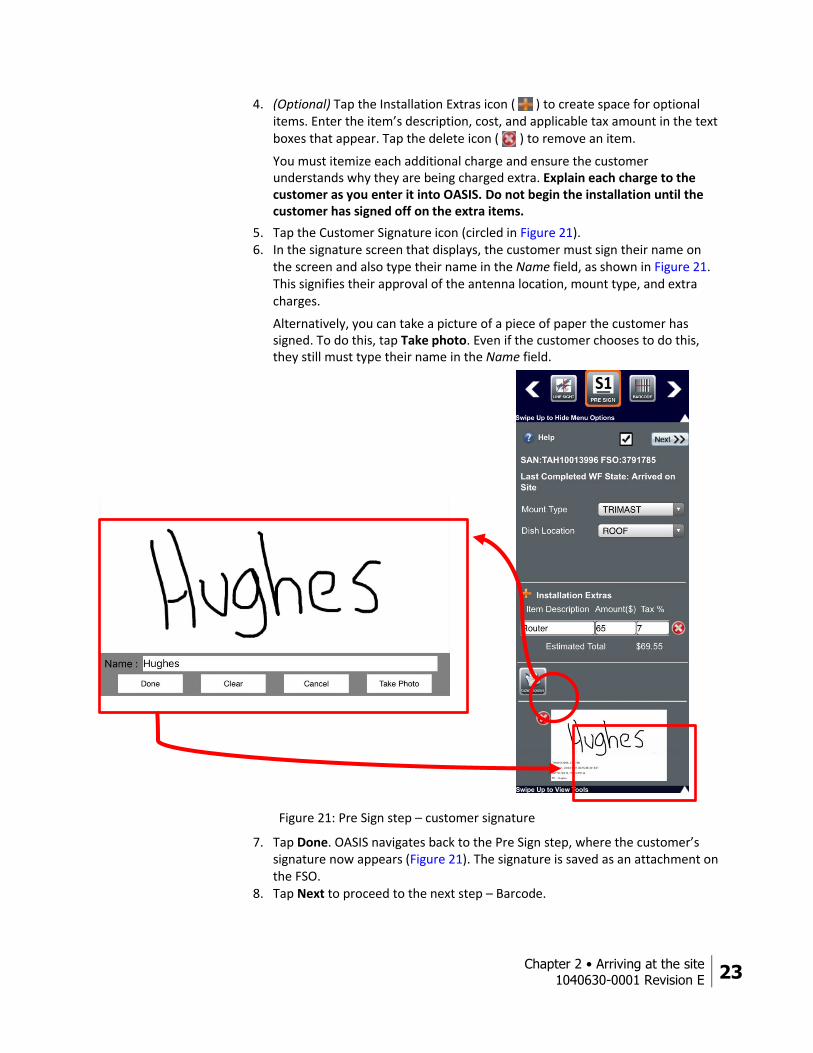
4. (Optional) Tap the Installation Extras icon ( ) to create space for optional items. Enter the item’s description, cost, and applicable tax amount in the text boxes that appear. Tap the delete icon ( ) to remove an item.
You must itemize each additional charge and ensure the customer understands why they are being charged extra. Explain each charge to the customer as you enter it into OASIS. Do not begin the installation until the customer has signed off on the extra items.
5. Tap the Customer Signature icon (circled in Figure 21). 6. In the signature screen that displays, the customer must sign their name on
the screen and also type their name in the Name field, as shown in Figure 21. This signifies their approval of the antenna location, mount type, and extra charges.
Alternatively, you can take a picture of a piece of paper the customer has signed. To do this, tap Take photo. Even if the customer chooses to do this, they still must type their name in the Name field.
Figure 21: Pre Sign step – customer signature
7. Tap Done. OASIS navigates back to the Pre Sign step, where the customer’s signature now appears (Figure 21). The signature is saved as an attachment on the FSO.
8. Tap Next to proceed to the next step – Barcode.
24 Chapter 2 • Arriving at the site
1040630-0001 Revision E
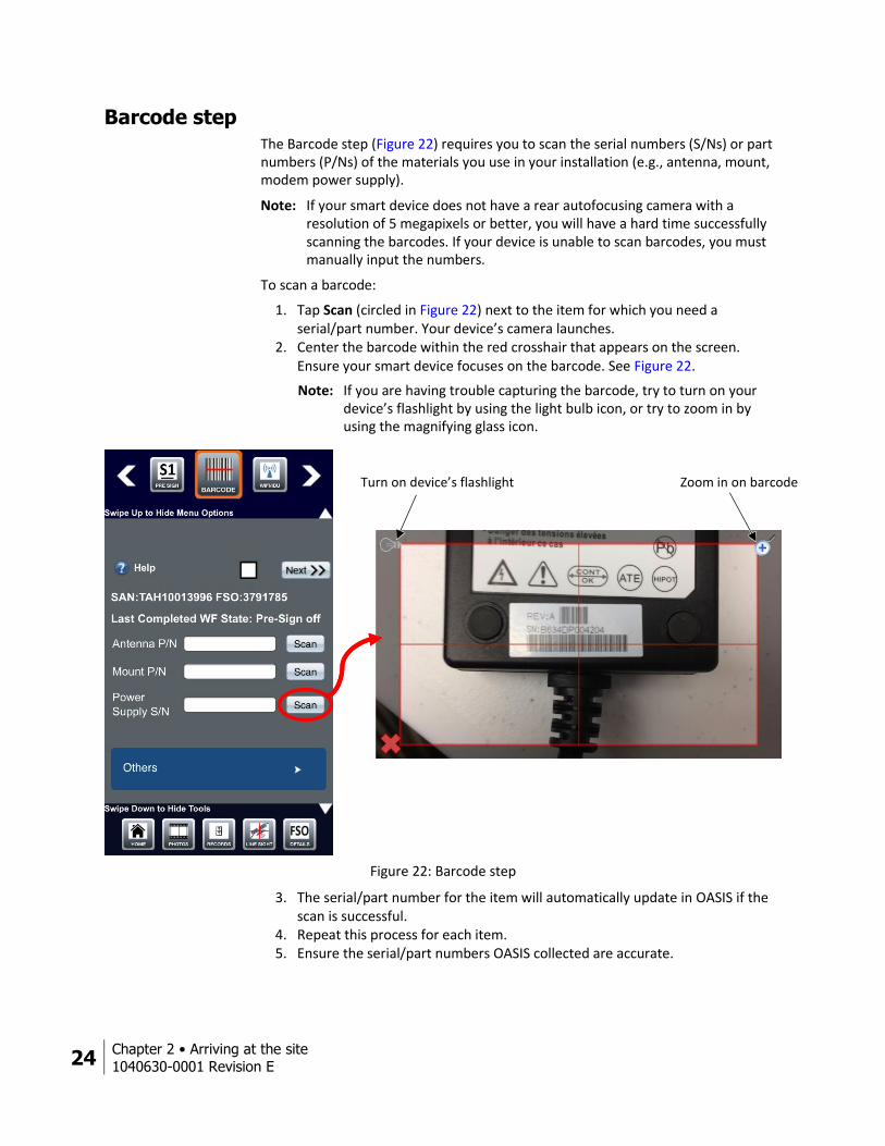
Barcode step The Barcode step (Figure 22) requires you to scan the serial numbers (S/Ns) or part numbers (P/Ns) of the materials you use in your installation (e.g., antenna, mount, modem power supply).
Note: If your smart device does not have a rear autofocusing camera with a resolution of 5 megapixels or better, you will have a hard time successfully scanning the barcodes. If your device is unable to scan barcodes, you must manually input the numbers.
To scan a barcode:
1. Tap Scan (circled in Figure 22) next to the item for which you need a serial/part number. Your device’s camera launches.
2. Center the barcode within the red crosshair that appears on the screen. Ensure your smart device focuses on the barcode. See Figure 22.
Note: If you are having trouble capturing the barcode, try to turn on your device’s flashlight by using the light bulb icon, or try to zoom in by using the magnifying glass icon.
Figure 22: Barcode step
3. The serial/part number for the item will automatically update in OASIS if the scan is successful.
4. Repeat this process for each item. 5. Ensure the serial/part numbers OASIS collected are accurate.
Turn on device’s flashlight Zoom in on barcode
Chapter 2 • Arriving at the site
1040630-0001 Revision E 25
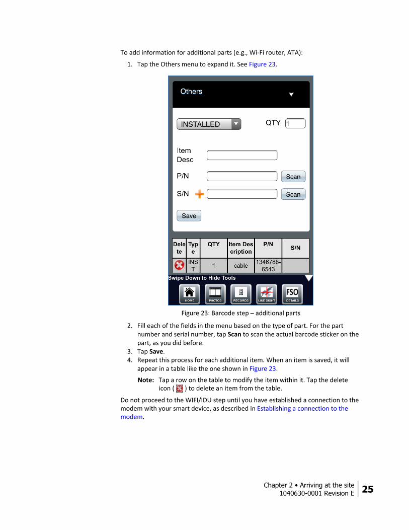
To add information for additional parts (e.g., Wi-Fi router, ATA):
1. Tap the Others menu to expand it. See Figure 23.
Figure 23: Barcode step – additional parts
2. Fill each of the fields in the menu based on the type of part. For the part number and serial number, tap Scan to scan the actual barcode sticker on the part, as you did before.
3. Tap Save. 4. Repeat this process for each additional item. When an item is saved, it will
appear in a table like the one shown in Figure 23.
Note: Tap a row on the table to modify the item within it. Tap the delete icon ( ) to delete an item from the table.
Do not proceed to the WIFI/IDU step until you have established a connection to the modem with your smart device, as described in Establishing a connection to the modem.

26 Chapter 2 • Arriving at the site
1040630-0001 Revision E
Establishing a connection to the modem Hughes recommends you use your own wireless router to connect to the modem with your smart device. If you are installing an HT2000W, you can also connect your smart device to the modem via the modem’s built-in wireless router; however, Hughes still recommends you use your own wireless router, because your smart device will lose connection to the HT2000W’s router whenever the modem reboots during installation.
The following few subsections describe how to configure your own wireless router, how to use that router to connect to a modem, and how to connect directly to the HT2000W’s built-in wireless router.
Configuring your own wireless router
Perform the steps in this section to set up your own wireless router to work with your smart device. Do not use a setup disk.
Note: Hughes provides a list of recommended routers on the Installation Portal.
You must perform the initial setup on a laptop or desktop computer with an Ethernet port, so the wireless router can be wired directly to the computer. This process only needs to be performed once. After the process is complete, the router can be used with any modem and smart device.
To set up the router:
1. Ensure the laptop or desktop computer is powered on. 2. Plug the wireless router into power and make sure it powers on. 3. Plug an Ethernet cable from the router’s WAN port into the Ethernet port on
the computer, as shown in Figure 24.
Figure 24: Ethernet connection to wireless router
4. Access the wireless router’s built-in web server by entering 192.168.1.1 in the URL field of an Internet browser on your laptop. If that does not work, try 192.168.0.1.
Ethernet cable
Chapter 2 • Arriving at the site
1040630-0001 Revision E 27
5. Log in to the router with the following credentials:
Username: admin
Password: password or admin
Note: Some routers may use different default credentials. Consult the router’s documentation for these credentials.
6. Navigate to the wireless settings of the router. 7. Change the SSID to HughesOASIS or something similar that you will
remember. 8. Apply the changes. The router may ask you to enter the username and
password again. 9. The router is now configured. Disconnect the Ethernet cable from the laptop
and the router.
Using your wireless router to connect to the modem
Follow the steps below to use your preconfigured router to connect to the modem.
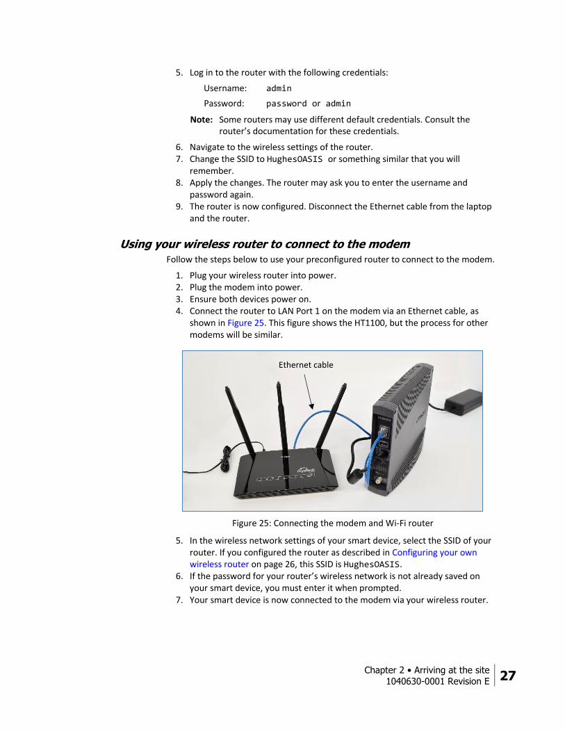
1. Plug your wireless router into power. 2. Plug the modem into power. 3. Ensure both devices power on. 4. Connect the router to LAN Port 1 on the modem via an Ethernet cable, as
shown in Figure 25. This figure shows the HT1100, but the process for other modems will be similar.
Figure 25: Connecting the modem and Wi-Fi router
5. In the wireless network settings of your smart device, select the SSID of your router. If you configured the router as described in Configuring your own wireless router on page 26, this SSID is HughesOASIS.
6. If the password for your router’s wireless network is not already saved on your smart device, you must enter it when prompted.
7. Your smart device is now connected to the modem via your wireless router.
Ethernet cable

28 Chapter 2 • Arriving at the site
1040630-0001 Revision E
Connecting to the HT2000W’s built-in router
Follow the steps below to connect directly to the HT2000W’s built-in router.
Note: The HT2000W’s router is unavailable when the modem is power cycling or rebooting. If your smart device loses connection to the modem during installation, this may be the cause. Because of this, Hughes recommends you use your own wireless router to connect to the modem.
1. In the wireless network settings of your smart device, select the SSID of either the 2.4 GHz or 5 GHz network of the HT2000W. Both SSIDs are given on the modem’s back label. See Figure 26.
2. When prompted to enter a password, enter the password given on the modem’s back label. The password is the same for both SSIDs. See Figure 26.
Figure 26: HT2000W back label
3. Your smart device is now connected to the HT2000W via the modem’s built-in wireless router.
SSIDs (network names)
Network password
Chapter 2 • Arriving at the site
1040630-0001 Revision E 29
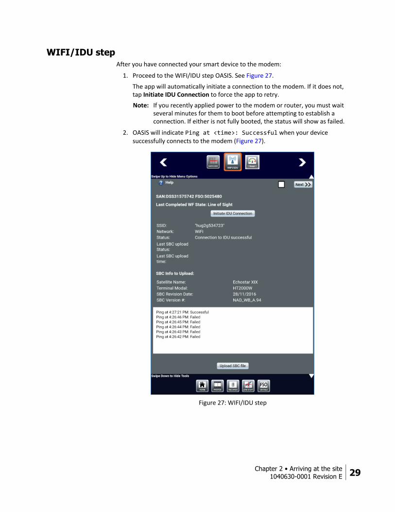
WIFI/IDU step After you have connected your smart device to the modem:
1. Proceed to the WIFI/IDU step OASIS. See Figure 27.
The app will automatically initiate a connection to the modem. If it does not, tap Initiate IDU Connection to force the app to retry.
Note: If you recently applied power to the modem or router, you must wait several minutes for them to boot before attempting to establish a connection. If either is not fully booted, the status will show as failed.
2. OASIS will indicate Ping at <time>: Successful when your device successfully connects to the modem (Figure 27).
Figure 27: WIFI/IDU step
30 Chapter 2 • Arriving at the site
1040630-0001 Revision E
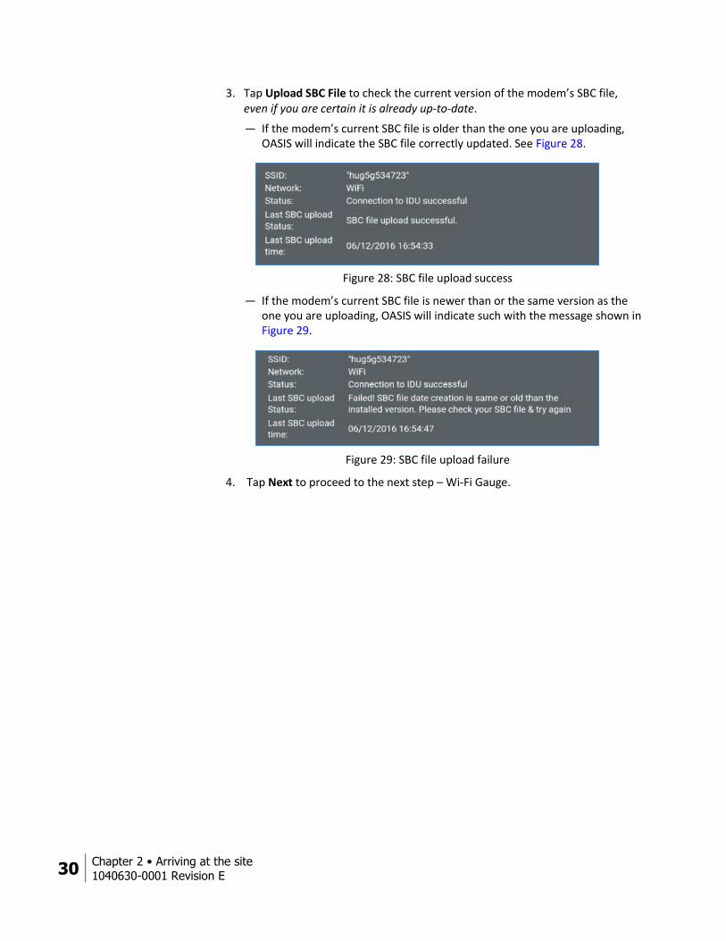
3. Tap Upload SBC File to check the current version of the modem’s SBC file, even if you are certain it is already up-to-date.
— If the modem’s current SBC file is older than the one you are uploading, OASIS will indicate the SBC file correctly updated. See Figure 28.
Figure 28: SBC file upload success
— If the modem’s current SBC file is newer than or the same version as the one you are uploading, OASIS will indicate such with the message shown in Figure 29.
Figure 29: SBC file upload failure
4. Tap Next to proceed to the next step – Wi-Fi Gauge.
Chapter 2 • Arriving at the site
1040630-0001 Revision E 31
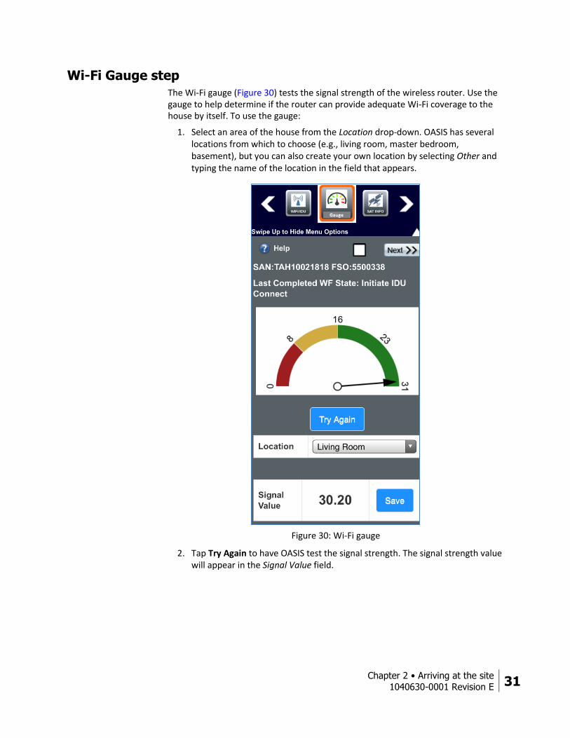
Wi-Fi Gauge step The Wi-Fi gauge (Figure 30) tests the signal strength of the wireless router. Use the gauge to help determine if the router can provide adequate Wi-Fi coverage to the house by itself. To use the gauge:
1. Select an area of the house from the Location drop-down. OASIS has several locations from which to choose (e.g., living room, master bedroom, basement), but you can also create your own location by selecting Other and typing the name of the location in the field that appears.
Figure 30: Wi-Fi gauge
2. Tap Try Again to have OASIS test the signal strength. The signal strength value will appear in the Signal Value field.
32 Chapter 2 • Arriving at the site
1040630-0001 Revision E
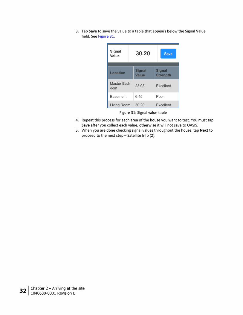
3. Tap Save to save the value to a table that appears below the Signal Value field. See Figure 31.
Figure 31: Signal value table
4. Repeat this process for each area of the house you want to test. You must tap Save after you collect each value, otherwise it will not save to OASIS.
5. When you are done checking signal values throughout the house, tap Next to proceed to the next step – Satellite Info (2).

Chapter 2 • Arriving at the site
1040630-0001 Revision E 33
Sat Info step The second Sat Info step (Figure 32) sends latitude and longitude information to the modem to put it into pointing mode. The Sat Name, Sat Location, Lat, Long, Az, El, and Tilt fields on the screen will populate automatically.
Figure 32: Sat Info step
The Pol, Beam, and Outroute fields may have values, but these are the default values. To calculate the correct values for pointing:
Note: OASIS may take some time to respond during the following steps. Follow the logs at the bottom of the Sat Info screen to check the app’s progress.
1. Tap Submit Install Parameters. 2. Tap Yes on the pop-up warning message that asks if you want to start the
installation. 3. Tap Ok on the success message that says pointing is in progress.
34 Chapter 2 • Arriving at the site
1040630-0001 Revision E
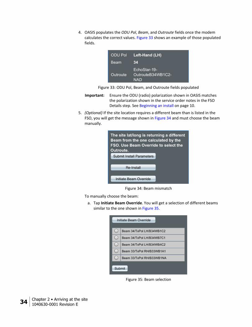
4. OASIS populates the ODU Pol, Beam, and Outroute fields once the modem calculates the correct values. Figure 33 shows an example of those populated fields.
Figure 33: ODU Pol, Beam, and Outroute fields populated
Important: Ensure the ODU (radio) polarization shown in OASIS matches the polarization shown in the service order notes in the FSO Details step. See Beginning an install on page 10.
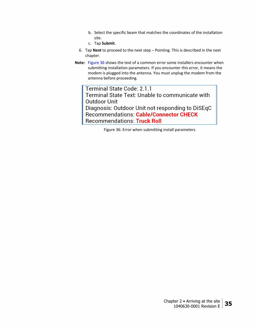
5. (Optional) If the site location requires a different beam than is listed in the FSO, you will get the message shown in Figure 34 and must choose the beam manually.
Figure 34: Beam mismatch
To manually choose the beam:
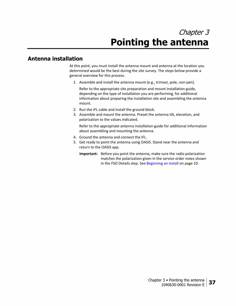
a. Tap Initiate Beam Override. You will get a selection of different beams similar to the one shown in Figure 35.
Figure 35: Beam selection
Chapter 2 • Arriving at the site
1040630-0001 Revision E 35
b. Select the specific beam that matches the coordinates of the installation site.
c. Tap Submit.
6. Tap Next to proceed to the next step – Pointing. This is described in the next chapter.
Note: Figure 36 shows the text of a common error some installers encounter when submitting installation parameters. If you encounter this error, it means the modem is plugged into the antenna. You must unplug the modem from the antenna before proceeding.
Figure 36: Error when submitting install parameters

Chapter 3 • Pointing the antenna
1040630-0001 Revision E 37
Chapter 3
Pointing the antenna
Antenna installation At this point, you must install the antenna mount and antenna at the location you determined would be the best during the site survey. The steps below provide a general overview for this process.
1. Assemble and install the antenna mount (e.g., trimast, pole, non-pen).
Refer to the appropriate site preparation and mount installation guide, depending on the type of installation you are performing, for additional information about preparing the installation site and assembling the antenna mount.
2. Run the IFL cable and install the ground block. 3. Assemble and mount the antenna. Preset the antenna tilt, elevation, and
polarization to the values indicated.
Refer to the appropriate antenna installation guide for additional information about assembling and mounting the antenna.
4. Ground the antenna and connect the IFL. 5. Get ready to point the antenna using OASIS. Stand near the antenna and
return to the OASIS app.
Important: Before you point the antenna, make sure the radio polarization matches the polarization given in the service order notes shown in the FSO Details step. See Beginning an install on page 10.
38 Chapter 3 • Pointing the antenna
1040630-0001 Revision E
Pointing step Note: You can only use the pointing functionality of OASIS during JUPITER
installations. To point the antenna during SPACEWAY installations, you must launch the satellite terminal’s user interface from your smart device’s Internet browser, then proceed as you normally would if using a laptop.
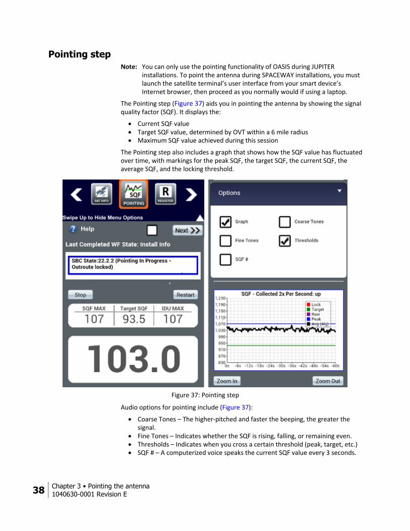
The Pointing step (Figure 37) aids you in pointing the antenna by showing the signal quality factor (SQF). It displays the:
Current SQF value Target SQF value, determined by OVT within a 6 mile radius Maximum SQF value achieved during this session
The Pointing step also includes a graph that shows how the SQF value has fluctuated over time, with markings for the peak SQF, the target SQF, the current SQF, the average SQF, and the locking threshold.
Figure 37: Pointing step
Audio options for pointing include (Figure 37):
Coarse Tones – The higher-pitched and faster the beeping, the greater the signal.
Fine Tones – Indicates whether the SQF is rising, falling, or remaining even. Thresholds – Indicates when you cross a certain threshold (peak, target, etc.) SQF # – A computerized voice speaks the current SQF value every 3 seconds.
Chapter 3 • Pointing the antenna
1040630-0001 Revision E 39
To point the antenna:
Do not attempt to point the antenna manually by pulling on the feed support arm. This can cause permanent damage to the antenna. Instead, use the antenna mechanical adjustments.
You may gently maneuver the antenna reflector to coarsely point the antenna, but only if the Az/El canister bolts are loose enough so that the reflector rotates easily.
1. Preset the antenna elevation to 1 degree above the number specified in the Sat Info step in OASIS. This helps compensate for any elevation loss caused by the loose antenna canister. Remember to align the elevation value with the black line under the elevation bolt.
2. Sweep the antenna in the direction of the azimuth value until you to get an SQF above 30, indicating you acquired the satellite.
3. Continue to carefully sweep the antenna until you achieve an SQF value of 50 or more.
4. Lock down the canister bolts to steady the antenna on the mount. You will now begin to fine-point the antenna.
Note: After you have locked down the canister bolts, do not attempt to adjust the antenna by grabbing the reflector. This will damage the reflector.
5. Wait for the SQF to settle on a value, then use the appropriately sized wrench for the antenna (found in the manual specific to that antenna) to fine-tune the antenna’s azimuth and elevation adjustments. Continue until you achieve the highest possible SQF value.
6. When the signals are peaked, tighten the azimuth and elevation bolts completely.
Note: Because slight movement of the antenna occurs during lockdown, always measure the signal peak value after locking down the antenna.
7. When you are done pointing, make sure all outdoor cable connections are weatherproofed with dielectric grease and securely tightened. A loose connector will degrade SQF. Depending on your installation environment, additional weatherproofing may also be needed.
Note: Use cable ties and cable hangers that are resistant to ultraviolet rays to secure all outdoor cables.
40 Chapter 3 • Pointing the antenna
1040630-0001 Revision E
Hughes-approved connectors, in conjunction with the dielectric grease on the F-connector threads, provide weatherproofing for outdoor connections. These connectors should be used in new installations, upgrades, and any repairs.
Outdoor connectors on radios and ground blocks that are in areas with corrosive environments (e.g., salt air) may need additional weatherproofing, such as weatherproofing tape or a weather boot filled with dielectric grease.
8. Tap Next to proceed to the next step, Register, found in Chapter 4 – Registering and activating the modem.
Chapter 4 • Registering and activating the modem
1040630-0001 Revision E 41
Chapter 4
Registering and activating the modem You can only register and activate a modem via OASIS during JUPITER installations. As such, all of the content in this chapter, with the exception of the OVT step, only pertains to JUPITER installations.
To register and activate the modem during installations of the HN9000 or HN7000 series modems, you must launch the modem’s user interface from your smart device’s Internet browser, then proceed as you normally would if using a laptop.
Register step
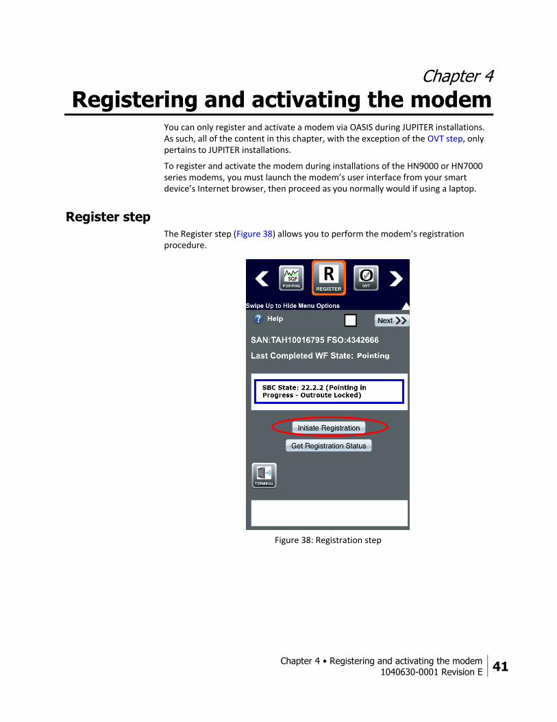
The Register step (Figure 38) allows you to perform the modem’s registration procedure.
Figure 38: Registration step
42 Chapter 4 • Registering and activating the modem
1040630-0001 Revision E
To register the modem:
1. Tap Initiate Registration (circled in Figure 38).
As the registration process progresses, the current modem state is shown in the top textbox and a summary of states the modem has achieved is shown in the bottom textbox.
Note: If the terminal fails to register, OASIS will recommend a solution in the bottom textbox.
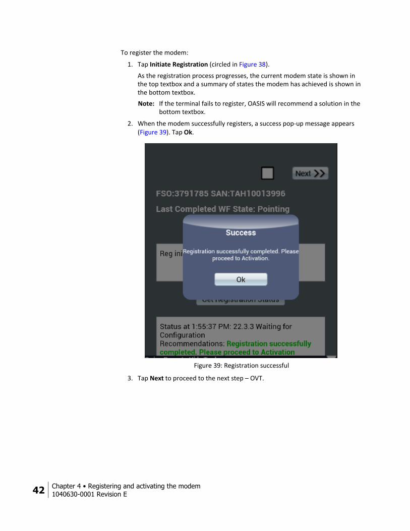
2. When the modem successfully registers, a success pop-up message appears (Figure 39). Tap Ok.
Figure 39: Registration successful
3. Tap Next to proceed to the next step – OVT.

Chapter 4 • Registering and activating the modem
1040630-0001 Revision E 43
OVT step The OVT step allows you to launch the onsite validation tool (OVT) from OASIS.
1. Tap Open OVT (circled in Figure 40) to launch the OVT in your smart device’s web browser.
Figure 40: OVT step

44 Chapter 4 • Registering and activating the modem
1040630-0001 Revision E
2. OASIS automatically fills the fields on the OVT pre-collection page (Figure 41). 3. Ensure the information is correct, then tap Launch OVT to open the tool.
Figure 41: OVT pre-collection page
4. OASIS automatically fills the fields in steps 1, 2, and 3 on the first page of OVT (Figure 42) if you already entered the information into the app. If the information does not automatically fill, you need to manually enter it.
5. Ensure all of the information is correct, then tap Proceed. OVT will begin to test the satellite connection.
Figure 42: OVT page 1
Chapter 4 • Registering and activating the modem
1040630-0001 Revision E 45
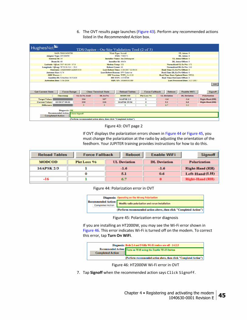
6. The OVT results page launches (Figure 43). Perform any recommended actions listed in the Recommended Action box.
Figure 43: OVT page 2
If OVT displays the polarization errors shown in Figure 44 or Figure 45, you must change the polarization at the radio by adjusting the orientation of the feedhorn. Your JUPITER training provides instructions for how to do this.
Figure 44: Polarization error in OVT
Figure 45: Polarization error diagnosis
If you are installing an HT2000W, you may see the Wi-Fi error shown in Figure 46. This error indicates Wi-Fi is turned off on the modem. To correct this error, tap Turn On WiFi.
Figure 46: HT2000W Wi-Fi error in OVT
7. Tap Signoff when the recommended action says Click Signoff.
46 Chapter 4 • Registering and activating the modem
1040630-0001 Revision E
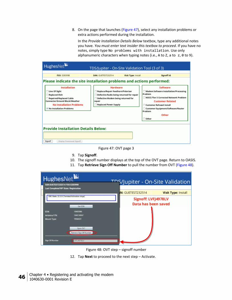
8. On the page that launches (Figure 47), select any installation problems or extra actions performed during the installation.
In the Provide Installation Details Below textbox, type any additional notes you have. You must enter text insider this textbox to proceed. If you have no notes, simply type No problems with installation. Use only alphanumeric characters when typing notes (i.e., A to Z, a to z, 0 to 9).
Figure 47: OVT page 3
9. Tap Signoff. 10. The signoff number displays at the top of the OVT page. Return to OASIS. 11. Tap Retrieve Sign Off Number to pull the number from OVT (Figure 48).
Figure 48: OVT step – signoff number
12. Tap Next to proceed to the next step – Activate.
Chapter 4 • Registering and activating the modem
1040630-0001 Revision E 47
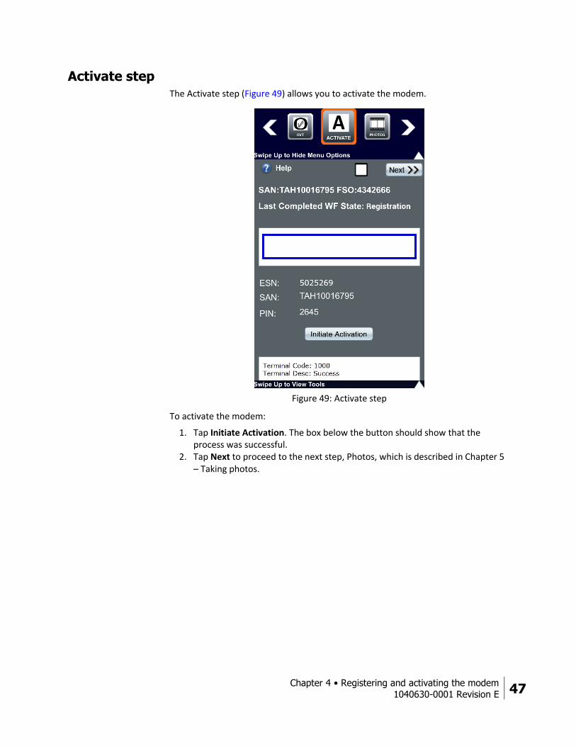
Activate step The Activate step (Figure 49) allows you to activate the modem.
Figure 49: Activate step
To activate the modem:
1. Tap Initiate Activation. The box below the button should show that the process was successful.
2. Tap Next to proceed to the next step, Photos, which is described in Chapter 5 – Taking photos.


Chapter 5 • Taking photos
1040630-0001 Revision E 49
Chapter 5
Taking photos At any point during the installation, you can take required photos by tapping the Photos button in the bottom toolbar of OASIS (Figure 50). You can take photos whenever is convenient for you during the installation process. For example, you can take a photo of the modem while you are setting it up.
Figure 50: Tools bar
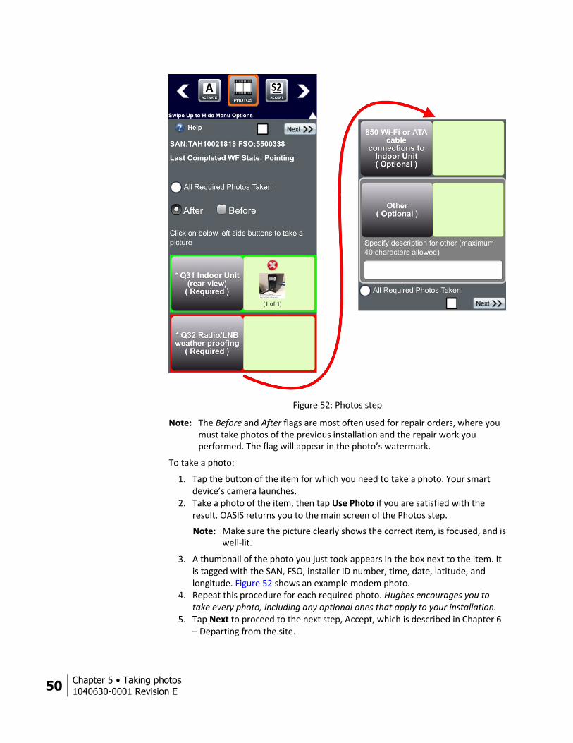
Photos step The Photos step (Figure 52 on page 50) walks you through which photos you need to take before departing from the installation site. Each photo has a corresponding button; Figure 51 shows three examples. The colored outlines have the following meanings.
Red – you still need to take the required photo. Green – you have taken the required photo. Gray – optional photo.
Figure 51: Photo button examples
50 Chapter 5 • Taking photos
1040630-0001 Revision E
Figure 52: Photos step
Note: The Before and After flags are most often used for repair orders, where you must take photos of the previous installation and the repair work you performed. The flag will appear in the photo’s watermark.
To take a photo:
1. Tap the button of the item for which you need to take a photo. Your smart device’s camera launches.
2. Take a photo of the item, then tap Use Photo if you are satisfied with the result. OASIS returns you to the main screen of the Photos step.
Note: Make sure the picture clearly shows the correct item, is focused, and is well-lit.
3. A thumbnail of the photo you just took appears in the box next to the item. It is tagged with the SAN, FSO, installer ID number, time, date, latitude, and longitude. Figure 52 shows an example modem photo.
4. Repeat this procedure for each required photo. Hughes encourages you to take every photo, including any optional ones that apply to your installation.
5. Tap Next to proceed to the next step, Accept, which is described in Chapter 6 – Departing from the site.
Chapter 6 • Departing from the site
1040630-0001 Revision E 51
Chapter 6
Departing from the site This chapter explains the final steps you must take to complete the installation.
Activating the customer’s service Prior to proceeding in OASIS, you must walk the customer through the service activation process on their computer or other device. The full details of service activation are described in your JUPITER training and in the modem guide specific to the type of modem you are installing, but the steps below summarize the process.
1. Connect the customer’s computer or other device to the modem either wirelessly or via a LAN connection.
2. Using a browser on the customer’s computer or device, enter www.systemcontrolcenter.com into the address bar to access the modem’s System Control Center.
3. Click on the Service Activation link in the System Control Center’s side menu, and then guide the customer through the HughesNet Welcome Experience. Encourage them to download the HughesNet Usage Meter to monitor their service plan data.
4. Show the customer how to access their modem’s settings to change basic options (such as the admin password and SSID names and passwords). For the HT2000W, be sure to explain to the customer the difference between the 2.4 GHz and 5 GHz Wi-Fi bands.
Return to OASIS once you have activated the customer’s service. You will be on the Accept step.
Accept step The Accept step helps ensure the installation was completed successfully and the customer has no further issues.
Important: A standard installation includes the connection of two customer devices to the Hughes modem by Ethernet cable or wirelessly, as well as a demonstration of browsing on each device. As part of an HT2000W installation, you must instruct the customer how to connect at least two of their smart devices to both the 2.4 GHz and 5 GHz bands of the wireless router. Be sure to show the customer the wireless network password on the back of the modem. Additional devices may be connected, but Hughes does not allow the installer to charge the customer for the extra connections.
52 Chapter 6 • Departing from the site
1040630-0001 Revision E
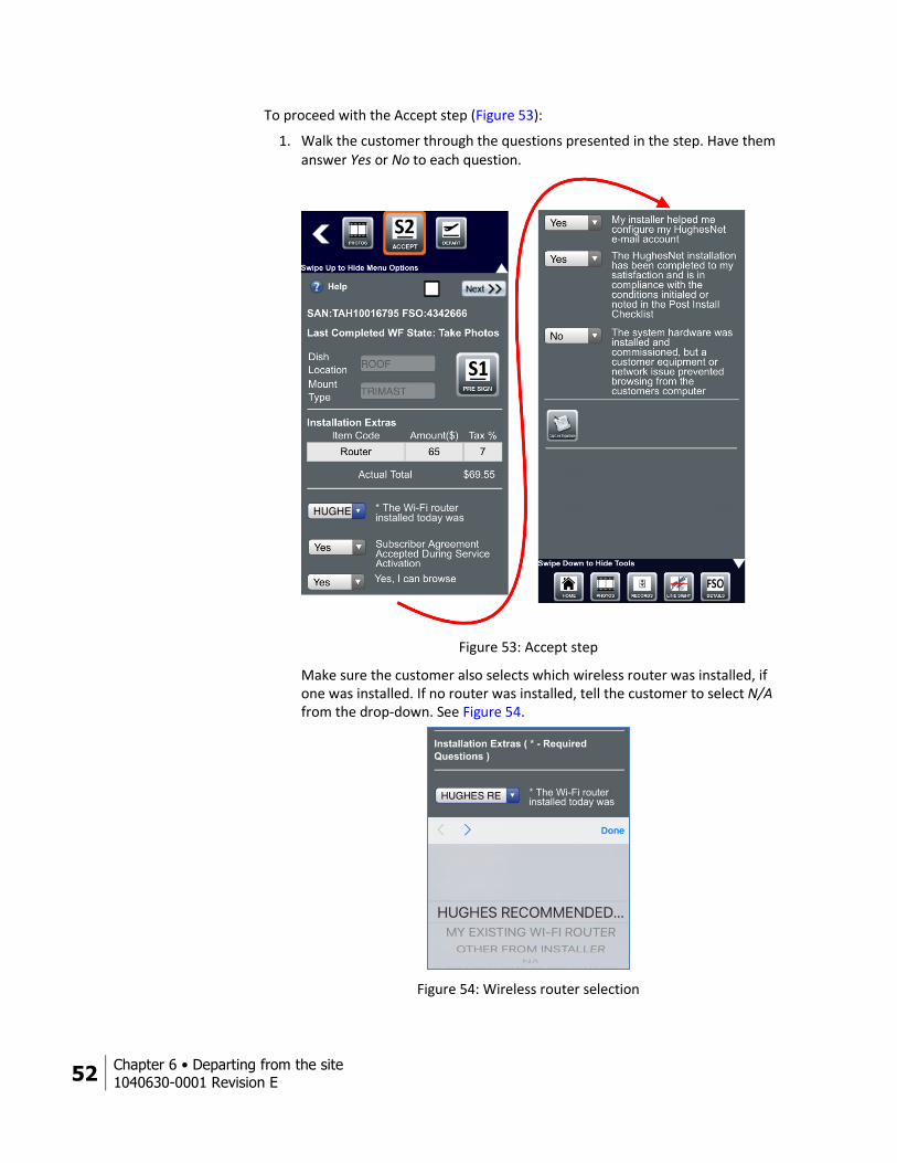
To proceed with the Accept step (Figure 53):
1. Walk the customer through the questions presented in the step. Have them answer Yes or No to each question.
Figure 53: Accept step
Make sure the customer also selects which wireless router was installed, if one was installed. If no router was installed, tell the customer to select N/A from the drop-down. See Figure 54.
Figure 54: Wireless router selection
Chapter 6 • Departing from the site
1040630-0001 Revision E 53
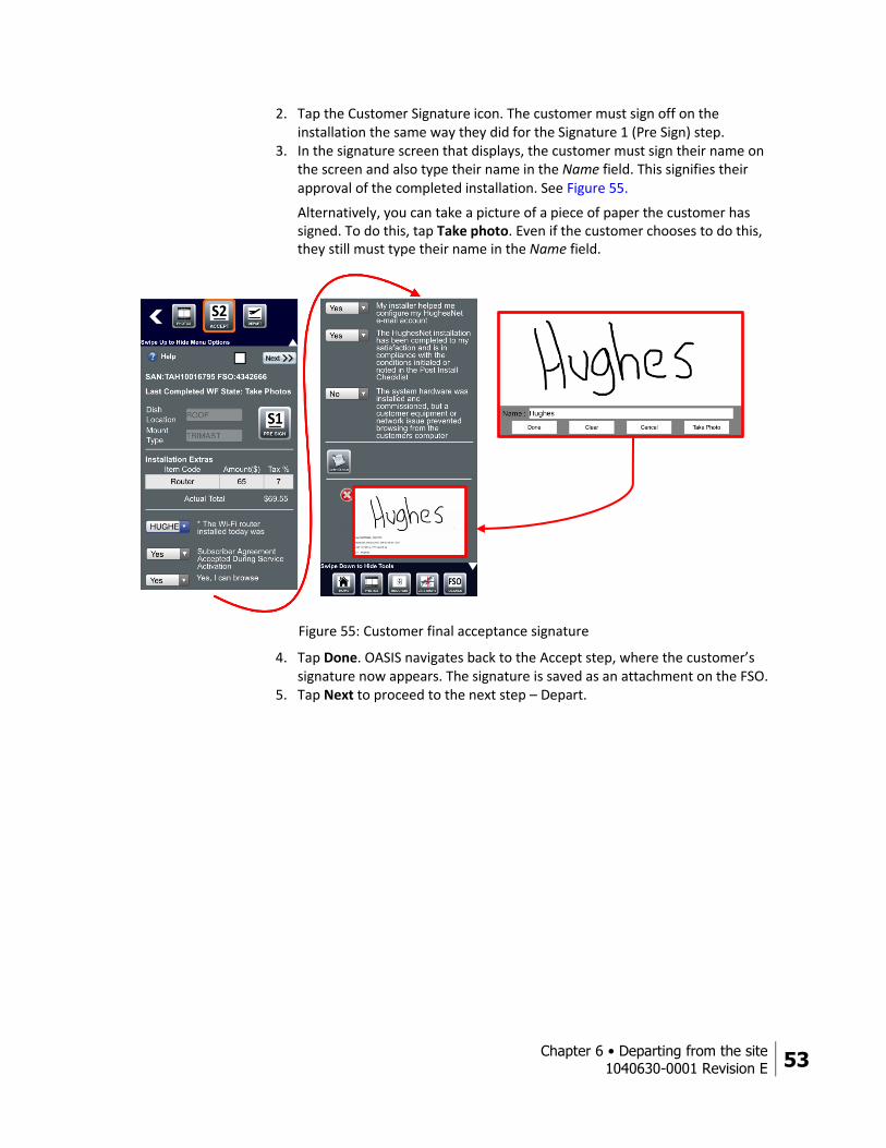
2. Tap the Customer Signature icon. The customer must sign off on the installation the same way they did for the Signature 1 (Pre Sign) step.
3. In the signature screen that displays, the customer must sign their name on the screen and also type their name in the Name field. This signifies their approval of the completed installation. See Figure 55.
Alternatively, you can take a picture of a piece of paper the customer has signed. To do this, tap Take photo. Even if the customer chooses to do this, they still must type their name in the Name field.
Figure 55: Customer final acceptance signature
4. Tap Done. OASIS navigates back to the Accept step, where the customer’s signature now appears. The signature is saved as an attachment on the FSO.
5. Tap Next to proceed to the next step – Depart.
54 Chapter 6 • Departing from the site
1040630-0001 Revision E
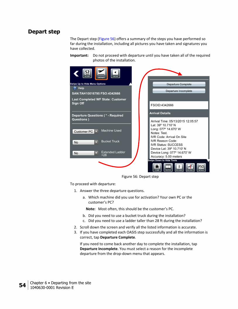
Depart step The Depart step (Figure 56) offers a summary of the steps you have performed so far during the installation, including all pictures you have taken and signatures you have collected.
Important: Do not proceed with departure until you have taken all of the required photos of the installation.
Figure 56: Depart step
To proceed with departure:
1. Answer the three departure questions.
a. Which machine did you use for activation? Your own PC or the customer’s PC?
Note: Most often, this should be the customer’s PC.
b. Did you need to use a bucket truck during the installation? c. Did you need to use a ladder taller than 28 ft during the installation?
2. Scroll down the screen and verify all the listed information is accurate. 3. If you have completed each OASIS step successfully and all the information is
correct, tap Departure Complete.
If you need to come back another day to complete the installation, tap Departure Incomplete. You must select a reason for the incomplete departure from the drop-down menu that appears.
Chapter 6 • Departing from the site
1040630-0001 Revision E 55
4. A textbox appears for you to add any additional notes about the completed installation. Tap Submit after you have entered your notes. Use only alphanumeric characters when typing notes (i.e., A to Z, a to z, 0 to 9).
Important: Any notes written in the app can be viewed by the customer. Make sure each note you write is appropriate and professional.
5. For a JUPITER installation, if a wireless router was included on the FSO and you did not record its MAC address and serial number in OVT, a prompt will remind you to rerun OVT to capture that information.
For a SPACEWAY installation, if a wireless router was included on the FSO, you must enter the MAC address and serial number of the router in OASIS when entering additional costs. You must also take a picture to verify both numbers for the dealer.
6. A warning pop-up message appears asking if you are sure you want to proceed. Tap Yes if you are sure you fully completed the installation.
Important: Once you proceed beyond the Depart step, you cannot edit any information in the FSO. Make sure you have all the required information and have completed each step fully before proceeding.
7. OASIS launches the FSO Step Summary page. See the next section, FSO Step Summary page.
56 Chapter 6 • Departing from the site
1040630-0001 Revision E
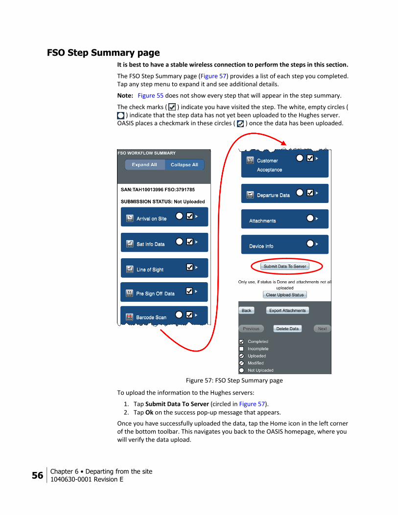
FSO Step Summary page It is best to have a stable wireless connection to perform the steps in this section.
The FSO Step Summary page (Figure 57) provides a list of each step you completed. Tap any step menu to expand it and see additional details.
Note: Figure 55 does not show every step that will appear in the step summary.
The check marks ( ) indicate you have visited the step. The white, empty circles ( ) indicate that the step data has not yet been uploaded to the Hughes server.
OASIS places a checkmark in these circles ( ) once the data has been uploaded.
Figure 57: FSO Step Summary page
To upload the information to the Hughes servers:
1. Tap Submit Data To Server (circled in Figure 57). 2. Tap Ok on the success pop-up message that appears.
Once you have successfully uploaded the data, tap the Home icon in the left corner of the bottom toolbar. This navigates you back to the OASIS homepage, where you will verify the data upload.
Chapter 6 • Departing from the site
1040630-0001 Revision E 57
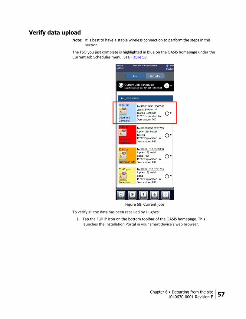
Verify data upload Note: It is best to have a stable wireless connection to perform the steps in this
section.
The FSO you just complete is highlighted in blue on the OASIS homepage under the Current Job Schedules menu. See Figure 58.
Figure 58: Current jobs
To verify all the data has been received by Hughes:
1. Tap the Full IP icon on the bottom toolbar of the OASIS homepage. This launches the Installation Portal in your smart device’s web browser.

58 Chapter 6 • Departing from the site
1040630-0001 Revision E
2. In your calendar of upcoming installations, tap the link for your current FSO (circled in Figure 59).
Figure 59: Select current FSO from Installation Portal calendar
3. On the page that launches, tap OASIS Step Summary (circled in Figure 60).
Figure 60: FSO page
Chapter 6 • Departing from the site
1040630-0001 Revision E 59
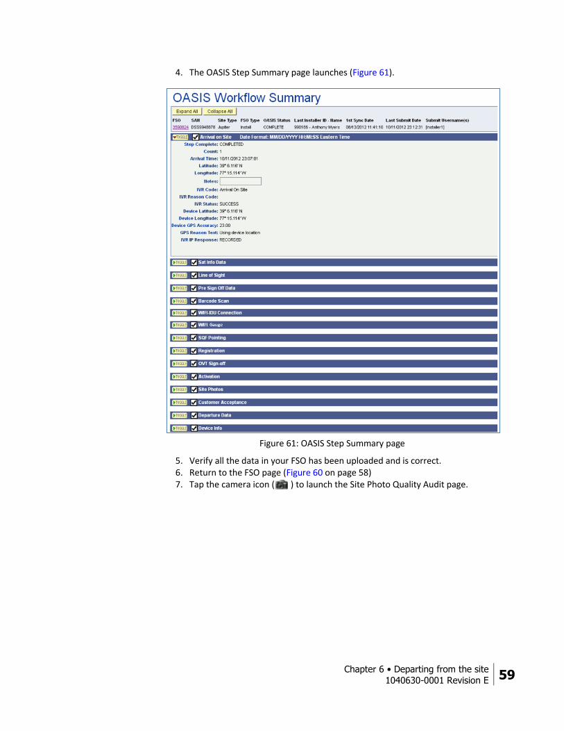
4. The OASIS Step Summary page launches (Figure 61).
Figure 61: OASIS Step Summary page
5. Verify all the data in your FSO has been uploaded and is correct. 6. Return to the FSO page (Figure 60 on page 58) 7. Tap the camera icon ( ) to launch the Site Photo Quality Audit page.
60 Chapter 6 • Departing from the site
1040630-0001 Revision E
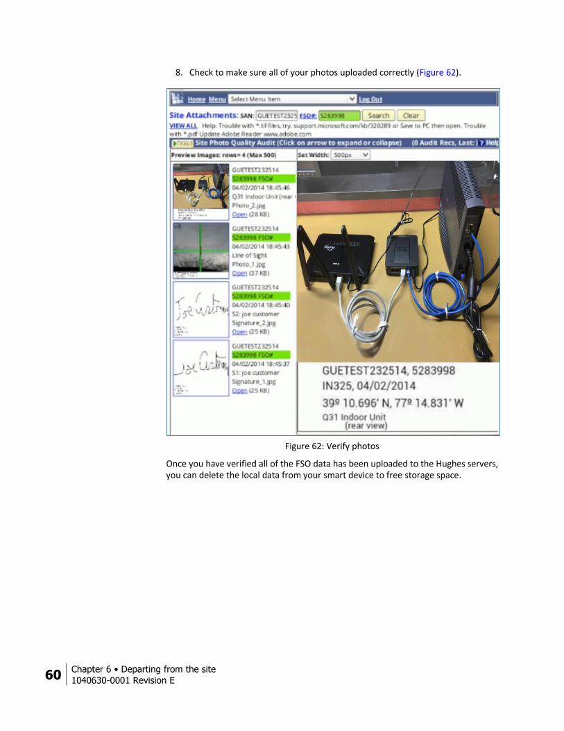
8. Check to make sure all of your photos uploaded correctly (Figure 62).
Figure 62: Verify photos
Once you have verified all of the FSO data has been uploaded to the Hughes servers, you can delete the local data from your smart device to free storage space.
Chapter 6 • Departing from the site
1040630-0001 Revision E 61
Delete local files To delete the local data of the FSO you just completed from your wireless device, follow the steps below. Hughes recommends you clear all FSO data weekly to maintain optimum OASIS performance. Only delete the data after you have confirmed it has successfully uploaded. Once it is deleted, you cannot get it back.
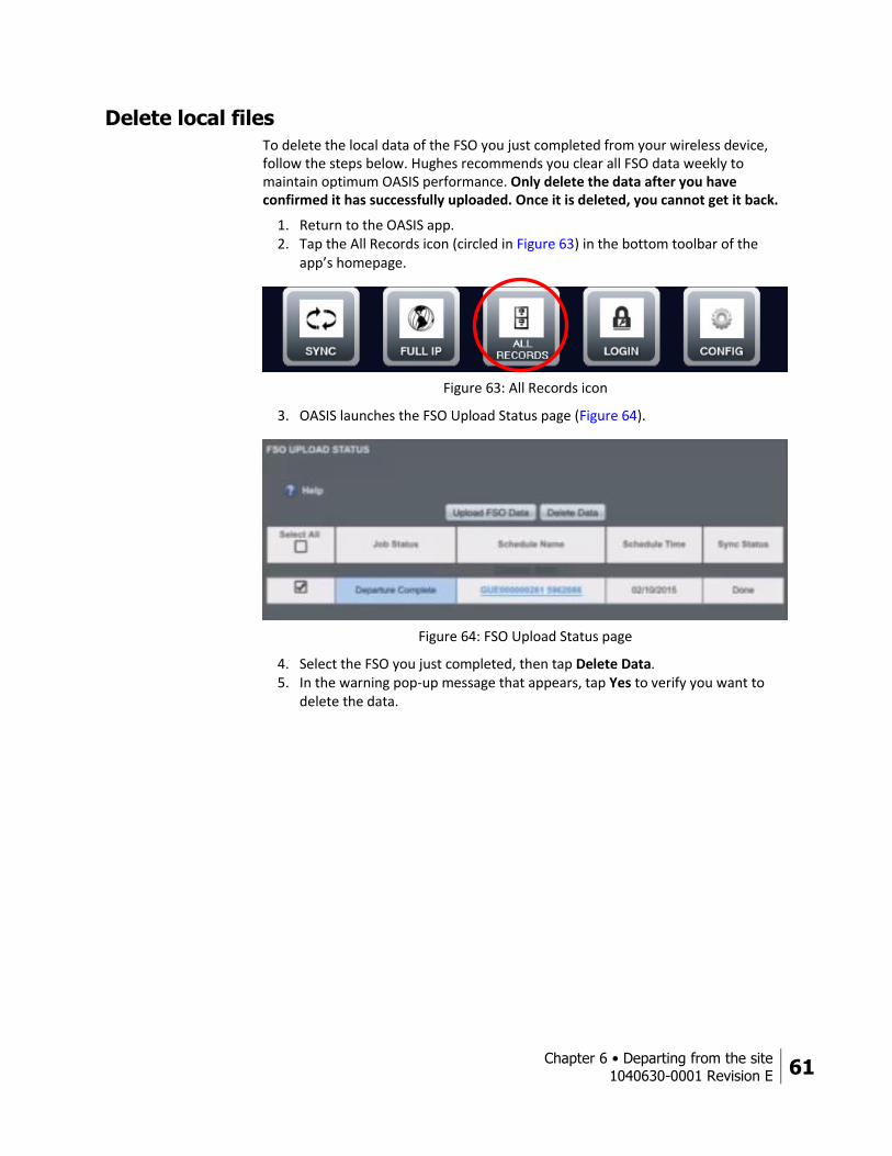
1. Return to the OASIS app. 2. Tap the All Records icon (circled in Figure 63) in the bottom toolbar of the
app’s homepage.
Figure 63: All Records icon
3. OASIS launches the FSO Upload Status page (Figure 64).
Figure 64: FSO Upload Status page
4. Select the FSO you just completed, then tap Delete Data. 5. In the warning pop-up message that appears, tap Yes to verify you want to
delete the data.

Appendix A • Performing repair orders
1040630-0001 Revision E 63
Appendix A
Performing repair orders Installers can use certain steps in OASIS to help with JUPITER repair orders.
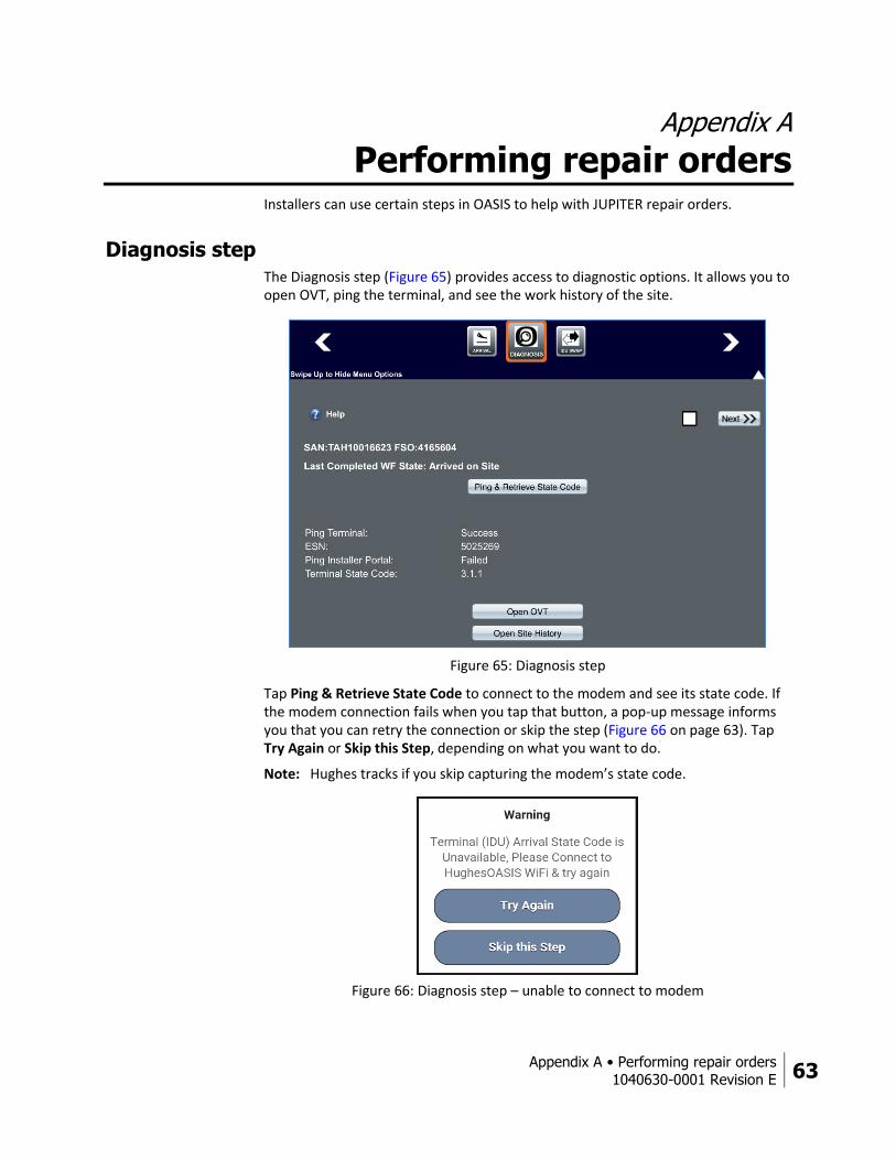
Diagnosis step The Diagnosis step (Figure 65) provides access to diagnostic options. It allows you to open OVT, ping the terminal, and see the work history of the site.
Figure 65: Diagnosis step
Tap Ping & Retrieve State Code to connect to the modem and see its state code. If the modem connection fails when you tap that button, a pop-up message informs you that you can retry the connection or skip the step (Figure 66 on page 63). Tap Try Again or Skip this Step, depending on what you want to do.
Note: Hughes tracks if you skip capturing the modem’s state code.
Figure 66: Diagnosis step – unable to connect to modem
64 Appendix A • Performing repair orders
1040630-0001 Revision E
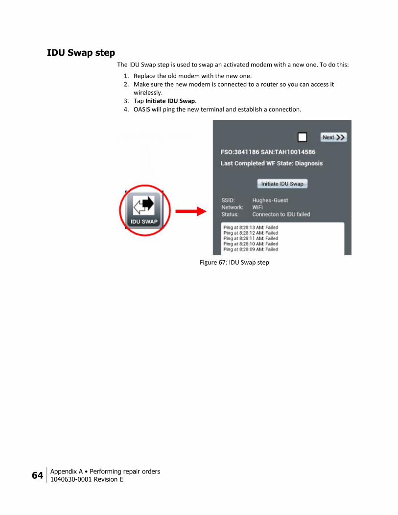
IDU Swap step The IDU Swap step is used to swap an activated modem with a new one. To do this:
1. Replace the old modem with the new one. 2. Make sure the new modem is connected to a router so you can access it
wirelessly. 3. Tap Initiate IDU Swap. 4. OASIS will ping the new terminal and establish a connection.
Figure 67: IDU Swap step
Appendix A • Performing repair orders
1040630-0001 Revision E 65
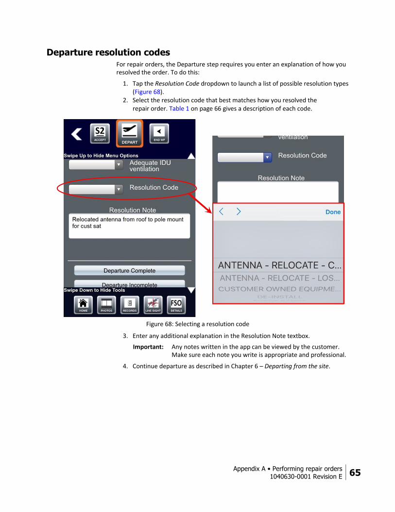
Departure resolution codes For repair orders, the Departure step requires you enter an explanation of how you resolved the order. To do this:
1. Tap the Resolution Code dropdown to launch a list of possible resolution types (Figure 68).
2. Select the resolution code that best matches how you resolved the repair order. Table 1 on page 66 gives a description of each code.
Figure 68: Selecting a resolution code
3. Enter any additional explanation in the Resolution Note textbox.
Important: Any notes written in the app can be viewed by the customer. Make sure each note you write is appropriate and professional.
4. Continue departure as described in Chapter 6 – Departing from the site.
66 Appendix A • Performing repair orders
1040630-0001 Revision E
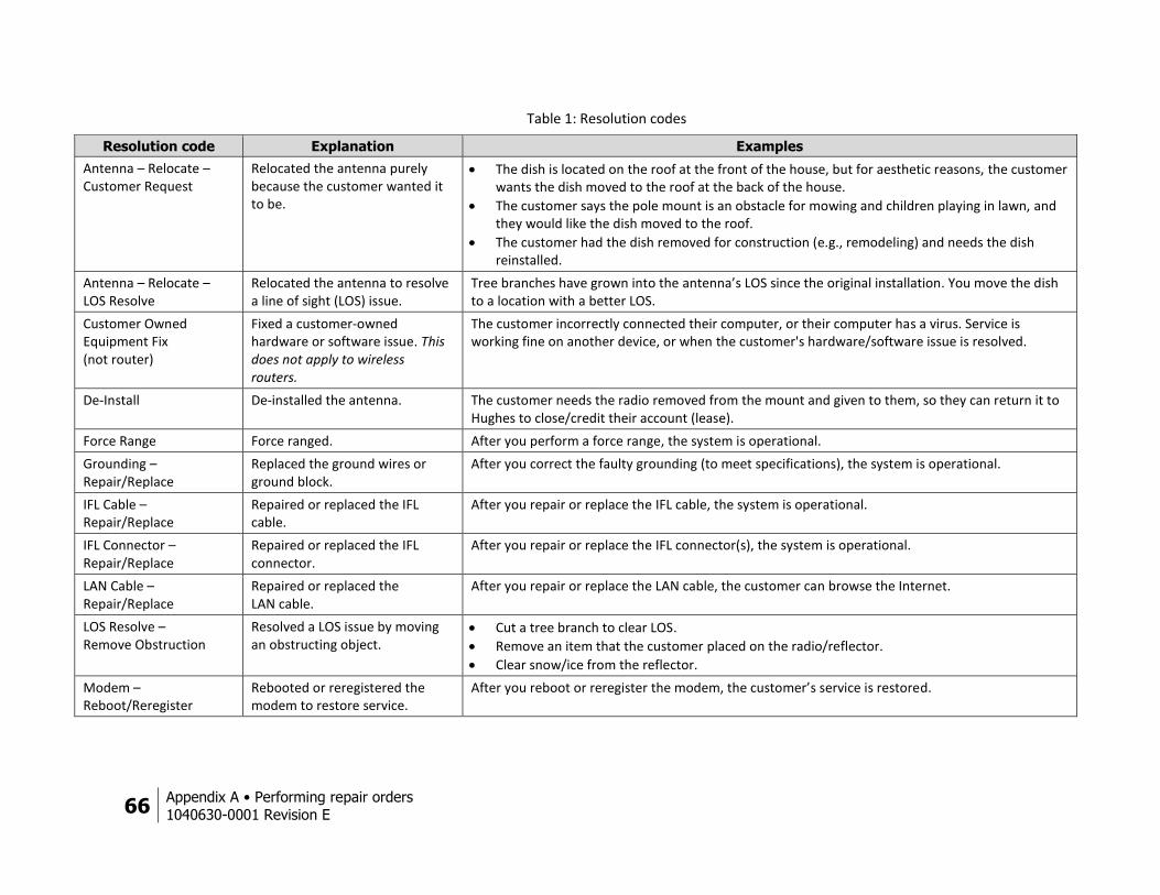
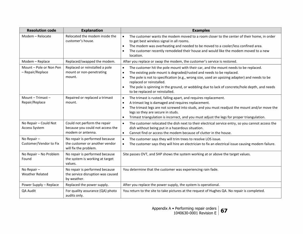
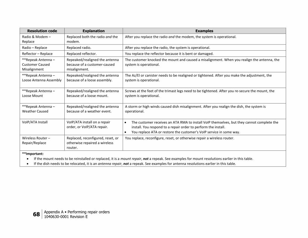
Table 1: Resolution codes
Resolution code Explanation Examples
Antenna – Relocate – Customer Request
Relocated the antenna purely because the customer wanted it to be.
The dish is located on the roof at the front of the house, but for aesthetic reasons, the customer wants the dish moved to the roof at the back of the house.
The customer says the pole mount is an obstacle for mowing and children playing in lawn, and they would like the dish moved to the roof.
The customer had the dish removed for construction (e.g., remodeling) and needs the dish reinstalled.
Antenna – Relocate – LOS Resolve
Relocated the antenna to resolve a line of sight (LOS) issue.
Tree branches have grown into the antenna’s LOS since the original installation. You move the dish to a location with a better LOS.
Customer Owned Equipment Fix (not router)
Fixed a customer-owned hardware or software issue. This does not apply to wireless routers.
The customer incorrectly connected their computer, or their computer has a virus. Service is working fine on another device, or when the customer's hardware/software issue is resolved.
De-Install De-installed the antenna. The customer needs the radio removed from the mount and given to them, so they can return it to Hughes to close/credit their account (lease).
Force Range Force ranged. After you perform a force range, the system is operational.
Grounding – Repair/Replace
Replaced the ground wires or ground block.
After you correct the faulty grounding (to meet specifications), the system is operational.
IFL Cable – Repair/Replace
Repaired or replaced the IFL cable.
After you repair or replace the IFL cable, the system is operational.
IFL Connector – Repair/Replace
Repaired or replaced the IFL connector.
After you repair or replace the IFL connector(s), the system is operational.
LAN Cable – Repair/Replace
Repaired or replaced the LAN cable.
After you repair or replace the LAN cable, the customer can browse the Internet.
LOS Resolve – Remove Obstruction
Resolved a LOS issue by moving an obstructing object.
Cut a tree branch to clear LOS.
Remove an item that the customer placed on the radio/reflector.
Clear snow/ice from the reflector.
Modem – Reboot/Reregister
Rebooted or reregistered the modem to restore service.
After you reboot or reregister the modem, the customer’s service is restored.
Appendix A • Performing repair orders
1040630-0001 Revision E 67
Resolution code Explanation Examples
Modem – Relocate Relocated the modem inside the customer’s house.
The customer wants the modem moved to a room closer to the center of their home, in order to get best wireless signal in all rooms.
The modem was overheating and needed to be moved to a cooler/less confined area.
The customer recently remodeled their house and would like the modem moved to a new location.
Modem – Replace Replaced/swapped the modem. After you replace or swap the modem, the customer’s service is restored.
Mount – Pole or Non Pen – Repair/Replace
Replaced or reinstalled a pole mount or non-penetrating mount.
The customer hit the pole mount with their car, and the mount needs to be replaced.
The existing pole mount is degraded/rusted and needs to be replaced.
The pole is not to specification (e.g., wrong size, used an upsizing adapter) and needs to be replaced or reinstalled.
The pole is spinning in the ground, or wobbling due to lack of concrete/hole depth, and needs to be replaced or reinstalled.
Mount – Trimast – Repair/Replace
Repaired or replaced a trimast mount.
The trimast is rusted, falling apart, and requires replacement.
A trimast leg is damaged and requires replacement.
The trimast legs are not screwed into studs, and you must readjust the mount and/or move the legs so they are secure in studs.
Trimast triangulation is incorrect, and you must adjust the legs for proper triangulation.
No Repair – Could Not Access System
Could not perform the repair because you could not access the modem or antenna.
The customer relocated the dish next to their electrical service entry, so you cannot access the dish without being put in a hazardous situation.
Cannot find or access the modem because of clutter in the house.
No Repair – Customer/Vendor to Fix
No repair is performed because the customer or another vendor will fix the problem.
The customer says they will trim trees to resolve LOS issue.
The customer says they will hire an electrician to fix an electrical issue causing modem failure.
No Repair – No Problem Found
No repair is performed because the system is working at target values.
Site passes OVT, and SHP shows the system working at or above the target values.
No Repair – Weather Related
No repair is performed because the service disruption was caused by weather.
You determine that the customer was experiencing rain fade.
Power Supply – Replace Replaced the power supply. After you replace the power supply, the system is operational.
QA Audit For quality assurance (QA) photo audits only.
You return to the site to take pictures at the request of Hughes QA. No repair is completed.
68 Appendix A • Performing repair orders
1040630-0001 Revision E
Resolution code Explanation Examples
Radio & Modem – Replace
Replaced both the radio and the modem.
After you replace the radio and the modem, the system is operational.
Radio – Replace Replaced radio. After you replace the radio, the system is operational.
Reflector – Replace Replaced reflector. You replace the reflector because it is bent or damaged.
**Repeak Antenna – Customer Caused Misalignment
Repeaked/realigned the antenna because of a customer-caused misalignment.
The customer knocked the mount and caused a misalignment. When you realign the antenna, the system is operational.
**Repeak Antenna – Loose Antenna Assembly
Repeaked/realigned the antenna because of a loose assembly.
The Az/El or canister needs to be realigned or tightened. After you make the adjustment, the system is operational.
**Repeak Antenna – Loose Mount
Repeaked/realigned the antenna because of a loose mount.
Screws at the feet of the trimast legs need to be tightened. After you re-secure the mount, the system is operational.
**Repeak Antenna – Weather Caused
Repeaked/realigned the antenna because of a weather event.
A storm or high winds caused dish misalignment. After you realign the dish, the system is operational.
VoIP/ATA Install VoIP/ATA install on a repair order, or VoIP/ATA repair.
The customer receives an ATA RMA to install VoIP themselves, but they cannot complete the install. You respond to a repair order to perform the install.
You replace ATA or restore the customer's VoIP service in some way.
Wireless Router – Repair/Replace
Replaced, reconfigured, reset, or otherwise repaired a wireless router.
You replace, reconfigure, reset, or otherwise repair a wireless router.
**Important:
If the mount needs to be reinstalled or replaced, it is a mount repair, not a repeak. See examples for mount resolutions earlier in this table.
If the dish needs to be relocated, it is an antenna repair, not a repeak. See examples for antenna resolutions earlier in this table.
Appendix B • Troubleshooting
1040630-0001 Revision E 69
Appendix B
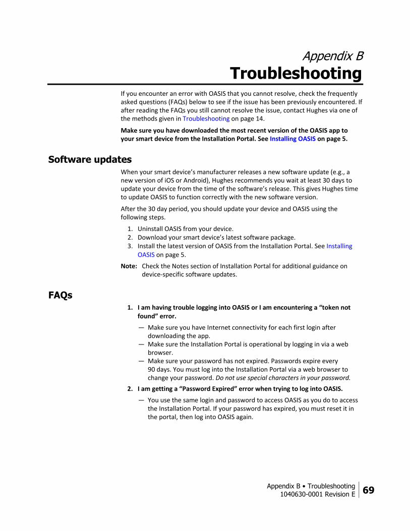
Troubleshooting If you encounter an error with OASIS that you cannot resolve, check the frequently asked questions (FAQs) below to see if the issue has been previously encountered. If after reading the FAQs you still cannot resolve the issue, contact Hughes via one of the methods given in Troubleshooting on page 14.
Make sure you have downloaded the most recent version of the OASIS app to your smart device from the Installation Portal. See Installing OASIS on page 5.
Software updates
When your smart device’s manufacturer releases a new software update (e.g., a new version of iOS or Android), Hughes recommends you wait at least 30 days to update your device from the time of the software’s release. This gives Hughes time to update OASIS to function correctly with the new software version.
After the 30 day period, you should update your device and OASIS using the following steps.
1. Uninstall OASIS from your device. 2. Download your smart device’s latest software package. 3. Install the latest version of OASIS from the Installation Portal. See Installing
OASIS on page 5.
Note: Check the Notes section of Installation Portal for additional guidance on device-specific software updates.
FAQs 1. I am having trouble logging into OASIS or I am encountering a “token not
found” error.
— Make sure you have Internet connectivity for each first login after downloading the app.
— Make sure the Installation Portal is operational by logging in via a web browser.
— Make sure your password has not expired. Passwords expire every 90 days. You must log into the Installation Portal via a web browser to change your password. Do not use special characters in your password.
2. I am getting a “Password Expired” error when trying to log into OASIS.
— You use the same login and password to access OASIS as you do to access the Installation Portal. If your password has expired, you must reset it in the portal, then log into OASIS again.
70 Appendix B • Troubleshooting
1040630-0001 Revision E
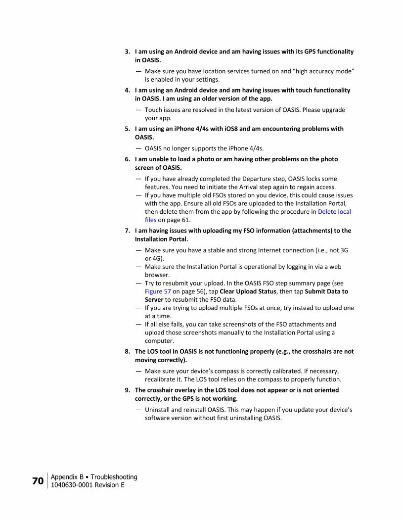
3. I am using an Android device and am having issues with its GPS functionality in OASIS.
— Make sure you have location services turned on and “high accuracy mode” is enabled in your settings.
4. I am using an Android device and am having issues with touch functionality in OASIS. I am using an older version of the app.
— Touch issues are resolved in the latest version of OASIS. Please upgrade your app.
5. I am using an iPhone 4/4s with iOS8 and am encountering problems with OASIS.
— OASIS no longer supports the iPhone 4/4s.
6. I am unable to load a photo or am having other problems on the photo screen of OASIS.
— If you have already completed the Departure step, OASIS locks some features. You need to initiate the Arrival step again to regain access.
— If you have multiple old FSOs stored on you device, this could cause issues with the app. Ensure all old FSOs are uploaded to the Installation Portal, then delete them from the app by following the procedure in Delete local files on page 61.
7. I am having issues with uploading my FSO information (attachments) to the Installation Portal.
— Make sure you have a stable and strong Internet connection (i.e., not 3G or 4G).
— Make sure the Installation Portal is operational by logging in via a web browser.
— Try to resubmit your upload. In the OASIS FSO step summary page (see Figure 57 on page 56), tap Clear Upload Status, then tap Submit Data to Server to resubmit the FSO data.
— If you are trying to upload multiple FSOs at once, try instead to upload one at a time.
— If all else fails, you can take screenshots of the FSO attachments and upload those screenshots manually to the Installation Portal using a computer.
8. The LOS tool in OASIS is not functioning properly (e.g., the crosshairs are not moving correctly).
— Make sure your device’s compass is correctly calibrated. If necessary, recalibrate it. The LOS tool relies on the compass to properly function.
9. The crosshair overlay in the LOS tool does not appear or is not oriented correctly, or the GPS is not working.
— Uninstall and reinstall OASIS. This may happen if you update your device’s software version without first uninstalling OASIS.
Appendix B • Troubleshooting
1040630-0001 Revision E 71
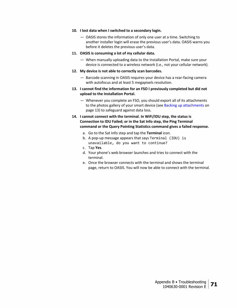
10. I lost data when I switched to a secondary login.
— OASIS stores the information of only one user at a time. Switching to another installer login will erase the previous user’s data. OASIS warns you before it deletes the previous user’s data.
11. OASIS is consuming a lot of my cellular data.
— When manually uploading data to the Installation Portal, make sure your device is connected to a wireless network (i.e., not your cellular network).
12. My device is not able to correctly scan barcodes.
— Barcode scanning in OASIS requires your device has a rear-facing camera with autofocus and at least 5 megapixels resolution.
13. I cannot find the information for an FSO I previously completed but did not upload to the Installation Portal.
— Whenever you complete an FSO, you should export all of its attachments to the photos gallery of your smart device (see Backing up attachments on page 13) to safeguard against data loss.
14. I cannot connect with the terminal. In WiFi/IDU step, the status is Connection to IDU Failed; or in the Sat Info step, the Ping Terminal command or the Query Pointing Statistics command gives a failed response.
a. Go to the Sat Info step and tap the Terminal icon. b. A pop-up message appears that says Terminal (IDU) is
unavailable, do you want to continue? c. Tap Yes. d. Your phone’s web browser launches and tries to connect with the
terminal. e. Once the browser connects with the terminal and shows the terminal
page, return to OASIS. You will now be able to connect with the terminal.


Index
1040630-0001 Revision E 73
Index
A
Accept step 51
customer signature 53
Activate step 47
Activating the customer’s service 51
Antenna installation 37
B
Backing up attachments 13
Barcode step 24
adding additional parts 25
Bottom toolbar 11
C
Checking the Wi-Fi signal 30
Common errors with OASIS 69
Completing the installation 51
Connecting to the HT2000W’s built-in router 28
Connecting to the modem
configuring your wireless router 26
using your wireless router to connect 27
Connecting to the modem 29
Current jobs
list and calendar views 9
D
Delete local files 61
Depart step 54
Departure 54
Departure step
resolution codes 65
Diagnosis step 63
Downloading OASIS 5
E
Exporting attachments 13
F
FAQs 69
Finding line of sight 20
FSO Details step 10
FSO information
upload to Hughes servers 56
verify data upload 57
FSO summary 56
I
IDU 29
connecting 29
entering pointing mode 33
IDU swap step 64
Indoor site survey 15
Installer feedback submittal form 14
Installing OASIS 5
Installing the antenna 37
L
Lauching OASIS 6
Leaving the installation site 54
Line of sight 20
Line of Sight step 20
Logging into OASIS 6
N
Navigating OASIS 11
74 Index
1040630-0001 Revision E
Navigation bar 11
O
OASIS homepage 8
bottom icons 9
Outdoor site survey 15
OVT step 43
P
Photos step 49
Pointing 38
mechanical adjustments 39
Pointing step 38
Pointing the antenna 38
Pre-sign step 22
customer signature 23
R
Radio 39
weatherproofing 39
Recording progress 56
Register step 41
Remove old FSOs 61
Repair orders 63
Diagnosis step 63
IDU swap step 64
resolution codes 65
Resolution codes 65
S
Sat Info step 19
Satellite modem 29
activation 47
connecting 29
entering pointing mode 33
registration 41
Satellite parameters 33
Satellite selection 19
Saving progress 13
Scanning barcodes 24
camera requirements 24
Selecting a satellite 19
Service activation 51
Site survey 22
indoor 15
outdoor 15
SQF 38
Step progression 11
Step summary 56
T
Taking photos 50
Terminal icon 12
Terminal user interface 12
Troubleshooting 14, 69
contacting Hughes 14
FAQs 69
smart device software updates 69
U
Upload FSO information 56
V
Validation 43
Verify FSO upload 57
W
Weatherproofing the radio 39
Wi-Fi Gauge step 30
WIFI/IDU step 29