Embed Size (px)
Citation preview

CONSTRUCTION TECHNOLOGY &maintenance
CEM 417
Stages for construction
WEEK 4
1. Building 2. Retaining walls, Drainage3. Road, Highway, Bridges4. Airports, Offshore/Marine structure
AIRPORT/AIRFEILDS, OFFSHORE/MARINE STRUCTURE

WEEK 4
At the end of week 4 lectures, student will be able to :
-Identify the different types of airfields and marine structures and their respective functions. (CO1; CO3)
Reference:-http://www.globalsecurity.org/military/library/policy/army/fm/5-430-00-2/Ch11.htmhttp://www.tpub.com/content/engineering/14071/css/14071_80.htm
AIRFIELDS
•Road construction and airfield construction have much in common, such as construction methods, equipment used, and sequence of operations. •Each road or airfield requires a subgrade, base course, and surface course. •The methods of cutting and falling, grading and compacting, and surfacing are all similar. As with roads, the responsibility for designing and laying out lies with the same person the engineering officer. •Again, as previously said for roads, you can expect involvement when airfield projects occur.

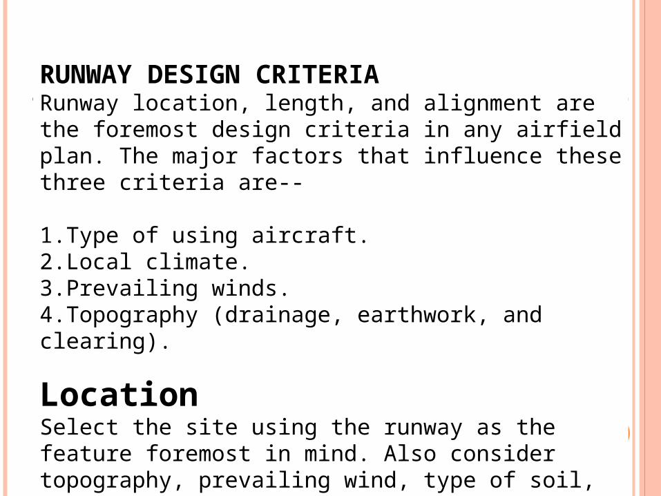
RUNWAY DESIGN CRITERIARunway location, length, and alignment are the foremost design criteria in any airfield plan. The major factors that influence these three criteria are--
1.Type of using aircraft. 2.Local climate. 3.Prevailing winds. 4.Topography (drainage, earthwork, and clearing).
Location
Select the site using the runway as the feature foremost in mind. Also consider topography, prevailing wind, type of soil, drainage characteristics. and the amount of clearing and earthwork necessary when selecting the site
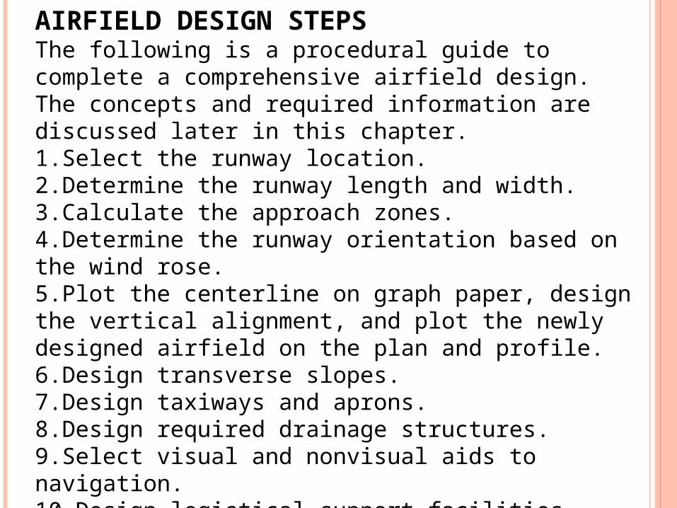
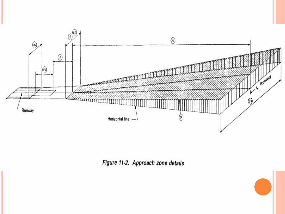
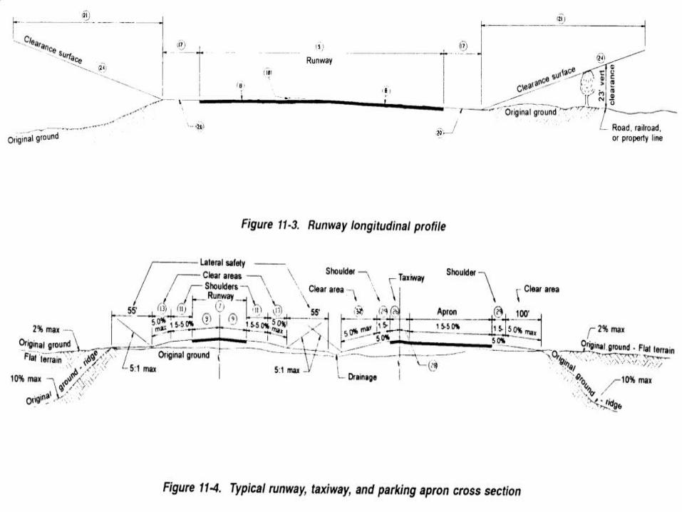
AIRFIELD DESIGN STEPSThe following is a procedural guide to complete a comprehensive airfield design. The concepts and required information are discussed later in this chapter. 1.Select the runway location. 2.Determine the runway length and width. 3.Calculate the approach zones. 4.Determine the runway orientation based on the wind rose. 5.Plot the centerline on graph paper, design the vertical alignment, and plot the newly designed airfield on the plan and profile. 6.Design transverse slopes. 7.Design taxiways and aprons. 8.Design required drainage structures. 9.Select visual and nonvisual aids to navigation. 10.Design logistical support facilities. 11.Design aircraft protection facilities.
Length When determining the runway length required for any aircraft, include the surface required for landing rolls or takeoff runs and a reasonable allowance for variations in pilot technique; psychological factors; wind, snow, or other surface conditions; and unforeseen mechanical failure. Determine runway length by applying several correction factors and a factor of safety to the takeoff ground run (TGR) established for the geographic and climatic conditions at the installation. Air density, which is governed by temperature and pressure at the site, greatly affects the ground run required for any type aircraft. Increases in either temperature or altitude reduce the density of air and increase the required ground run. Therefore, the length of runway required for a specific type of aircraft varies with the geographic location. The length of every airfield must be computed based on the average maximum temperature and the pressure altitude of the site.
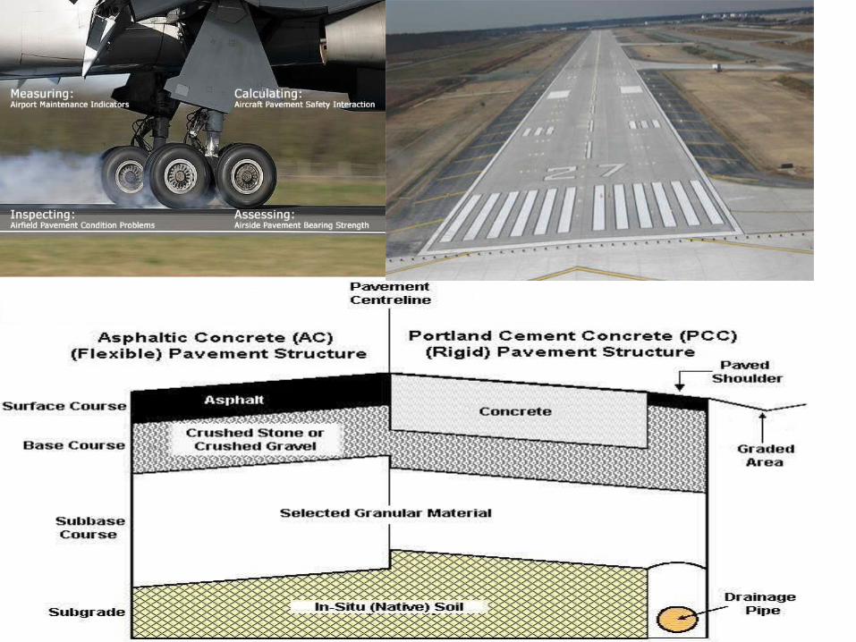
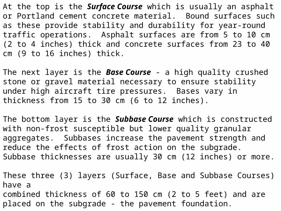
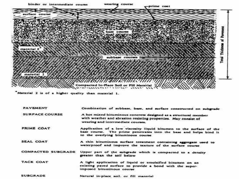
At the top is the Surface Course which is usually an asphalt or Portland cement concrete material. Bound surfaces such as these provide stability and durability for year-round traffic operations. Asphalt surfaces are from 5 to 10 cm (2 to 4 inches) thick and concrete surfaces from 23 to 40 cm (9 to 16 inches) thick.
The next layer is the Base Course - a high quality crushed stone or gravel material necessary to ensure stability under high aircraft tire pressures. Bases vary in thickness from 15 to 30 cm (6 to 12 inches).
The bottom layer is the Subbase Course which is constructed with non-frost susceptible but lower quality granular aggregates. Subbases increase the pavement strength and reduce the effects of frost action on the subgrade. Subbase thicknesses are usually 30 cm (12 inches) or more.
These three (3) layers (Surface, Base and Subbase Courses) have a combined thickness of 60 to 150 cm (2 to 5 feet) and are placed on the subgrade - the pavement foundation.
The Subgrade is the natural in-situ soil material which has been cut to grade, or in a fill section, is imported common material built up over the in-situ material. The subgrade must provide a stable and uniform support for the overlying pavement structure.
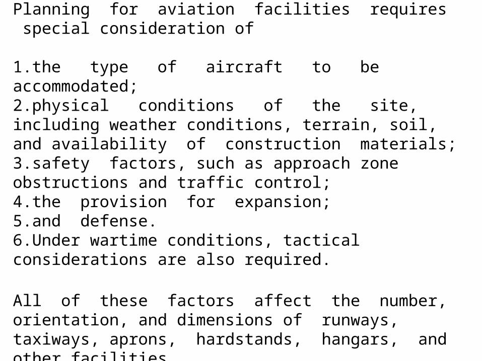
PLANNING AN AIRFIELDPlanning for aviation facilities requires special consideration of
1.the type of aircraft to be accommodated; 2.physical conditions of the site, including weather conditions, terrain, soil, and availability of construction materials; 3.safety factors, such as approach zone obstructions and traffic control; 4.the provision for expansion; 5.and defense. 6.Under wartime conditions, tactical considerations are also required.
All of these factors affect the number, orientation, and dimensions of runways, taxiways, aprons, hardstands, hangars, and other facilities.
SUBBASE AND BASE COURSE
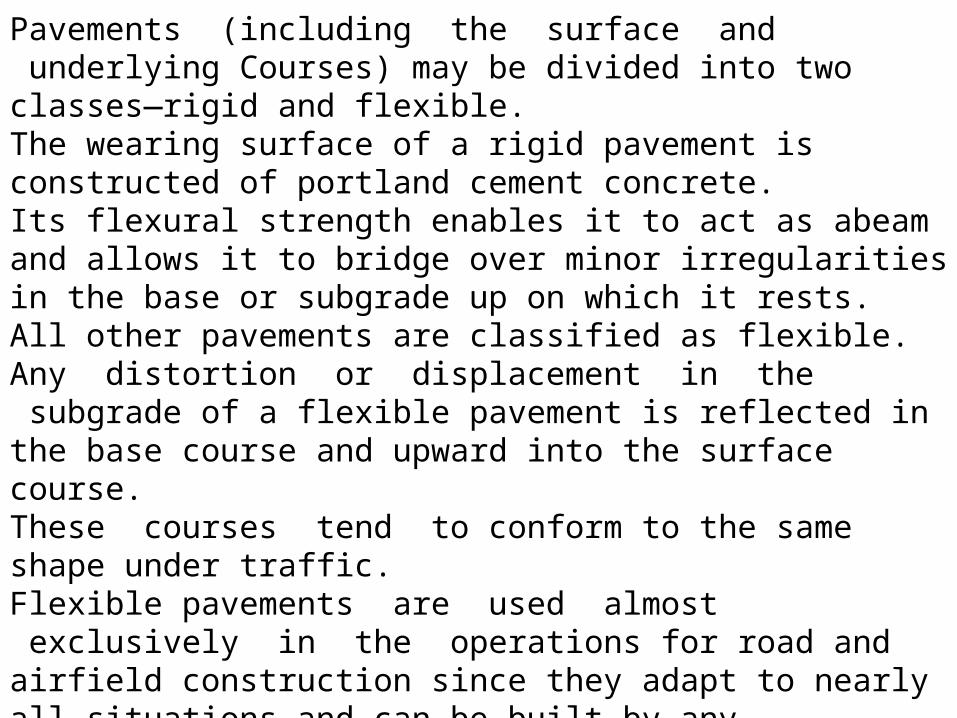
Pavements (including the surface and underlying Courses) may be divided into two classes—rigid and flexible. The wearing surface of a rigid pavement is constructed of portland cement concrete. Its flexural strength enables it to act as abeam and allows it to bridge over minor irregularities in the base or subgrade up on which it rests.All other pavements are classified as flexible. Any distortion or displacement in the subgrade of a flexible pavement is reflected in the base course and upward into the surface course. These courses tend to conform to the same shape under traffic. Flexible pavements are used almost exclusively in the operations for road and airfield construction since they adapt to nearly all situations and can be built by any construction battalion unit in the Naval Construction Force (NCF) ate.
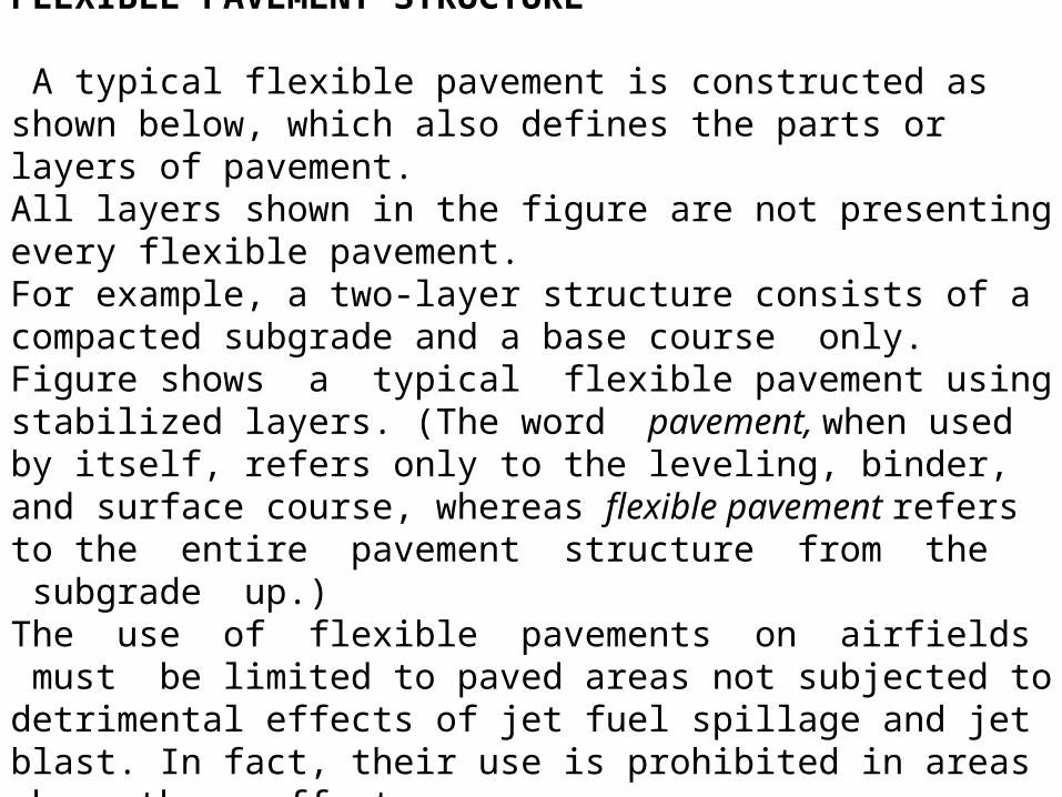
FLEXIBLE PAVEMENT STRUCTURE
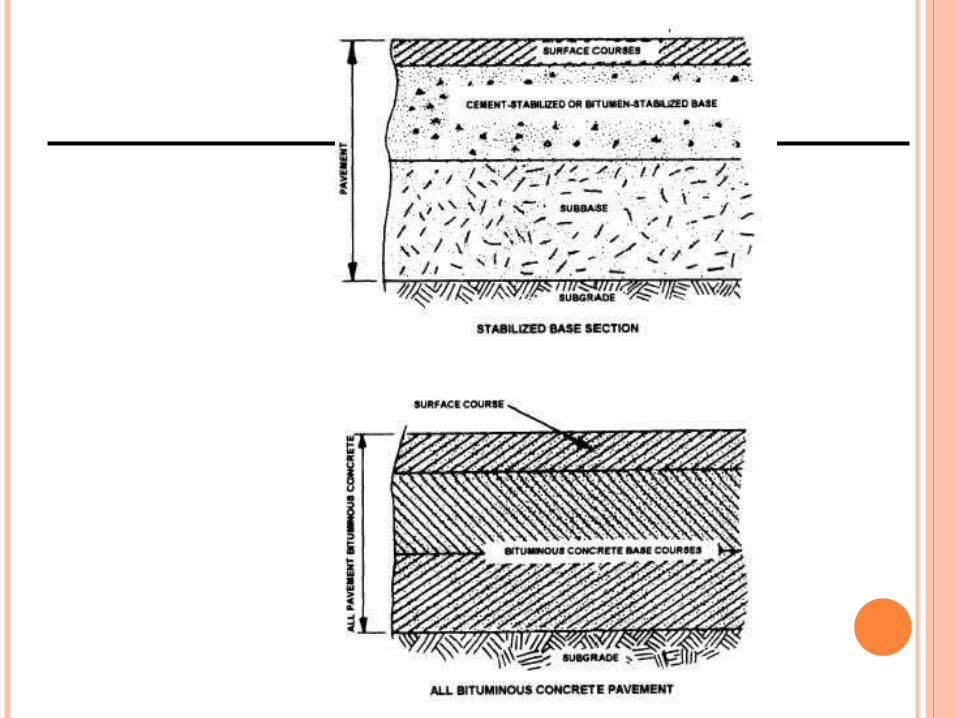
A typical flexible pavement is constructed as shown below, which also defines the parts or layers of pavement.All layers shown in the figure are not presenting every flexible pavement. For example, a two-layer structure consists of a compacted subgrade and a base course only. Figure shows a typical flexible pavement using stabilized layers. (The word pavement, when used by itself, refers only to the leveling, binder, and surface course, whereas flexible pavement refers to the entire pavement structure from the subgrade up.)The use of flexible pavements on airfields must be limited to paved areas not subjected to detrimental effects of jet fuel spillage and jet blast. In fact, their use is prohibited in areas where these effects are severe.
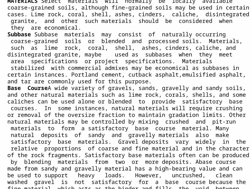
Flexible pavements are generally satisfactory for runway interiors, taxiways, shoulders, and overruns. Rigid pavements or special types of flexible pavement, such as tar rubber, should be specified in certain critical operational areas. MATERIALS Select materials will normally be locally available coarse-grained soils, although fine-grained soils may be used in certain cases. Lime rock, coral, shell, ashes, cinders, caliche, disintegrated granite, and other such materials should be considered when they are economical. Subbase Subbase materials may consist of naturally occurring coarse-grained soils or blended and processed soils. Materials, such as lime rock, coral, shell, ashes, cinders, caliche, and disintegrated granite, maybe used as subbases when they meet area specifications or project specifications. Materials stabilized with commercial admixes may be economical as subbases in certain instances. Portland cement, cutback asphalt,emulsified asphalt, and tar are commonly used for this purpose.Base CourseA wide variety of gravels, sands, gravelly and sandy soils, and other natural materials such as lime rock, corals, shells, and some caliches can be used alone or blended to provide satisfactory base courses. In some instances, natural materials will require crushing or removal of the oversize fraction to maintain gradation limits. Other natural materials may be controlled by mixing crushed and pit-run materials to form a satisfactory base course material. Many natural deposits of sandy and gravelly materials also make satisfactory base materials. Gravel deposits vary widely in the relative proportions of coarse and fine material and in the character of the rock fragments. Satisfactory base materials often can be produced by blending materials from two or more deposits. Abase course made from sandy and gravelly material has a high-bearing value and can be used to support heavy loads. However, uncrushed, clean washed gravel is not satisfactory for a base course because the fine material, which acts as the binder and fills the void between coarser aggregate, has been washed away. Sand and clay in a natural mixture maybe found in alluvial deposits varying in thickness from 1 to 20 feet. Often there are great variations in the proportions of sand and clay from the top to the bottom of a pit
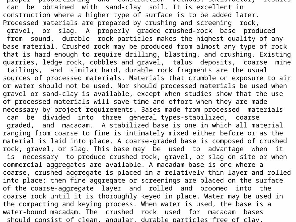
Deposits of partially disintegrated rock consisting of fragments of rock, clay, and mica flakes should not be confused with sand-clay soil. Mistaking such material for sand-clay is often a cause of base course failure because of reduced stability caused by the mica content. With proper proportioning and construction methods, satisfactory results can be obtained with sand-clay soil. It is excellent in construction where a higher type of surface is to be added later. Processed materials are prepared by crushing and screening rock, gravel, or slag. A properly graded crushed-rock base produced from sound, durable rock particles makes the highest quality of any base material. Crushed rock may be produced from almost any type of rock that is hard enough to require drilling, blasting, and crushing. Existing quarries, ledge rock, cobbles and gravel, talus deposits, coarse mine tailings, and similar hard, durable rock fragments are the usual sources of processed materials. Materials that crumble on exposure to air or water should not be used. Nor should processed materials be used when gravel or sand-clay is available, except when studies show that the use of processed materials will save time and effort when they are made necessary by project requirements. Bases made from processed materials can be divided into three general types-stabilized, coarse graded, and macadam. A stabilized base is one in which all material ranging from coarse to fine is intimately mixed either before or as the material is laid into place. A coarse-graded base is composed of crushed rock, gravel, or slag. This base may be used to advantage when it is necessary to produce crushed rock, gravel, or slag on site or when commercial aggregates are available. A macadam base is one where a coarse, crushed aggregate is placed in a relatively thin layer and rolled into place; then fine aggregate or screenings are placed on the surface of the coarse-aggregate layer and rolled and broomed into the coarse rock until it is thoroughly keyed in place. Water may be used in the compacting and keying process. When water is used, the base is a water-bound macadam. The crushed rock used for macadam bases should consist of clean, angular, durable particles free of clay, organic matter, and other objectional material or coating. Any hard, durable crushed aggregate can be used, provided the coarse aggregate is primarily one size and the fine aggregate will key into the coarse aggregate

Definition of Airport Categories
1.Commercial Service Airports are publicly owned airports that have at least 2,500 passenger boardings each calendar year and receive scheduled passenger service.2.Nonprimary Commercial Service Airports are Commercial Service Airports that have at least 2,500 and no more than 10,000 passenger boardings each year.3.Primary Airports are Commercial Service Airports that have more than 10,000 passenger boardings each year. 4.Cargo Service Airports are airports that, in addition to any other air transportation services that may be available, are served by aircraft providing air transportation of only cargo with a total annual landed weight of more than 100 million pounds. 5.Reliever Airports are airports designated by the FAA to relieve congestion at Commercial Service Airports and to provide improved general aviation access to the overall community. These may be publicly or privately-owned. commonly described as General Aviation Airports.
http://www.faa.gov/airports/planning_capacity/passenger_allcargo_stats/categories/
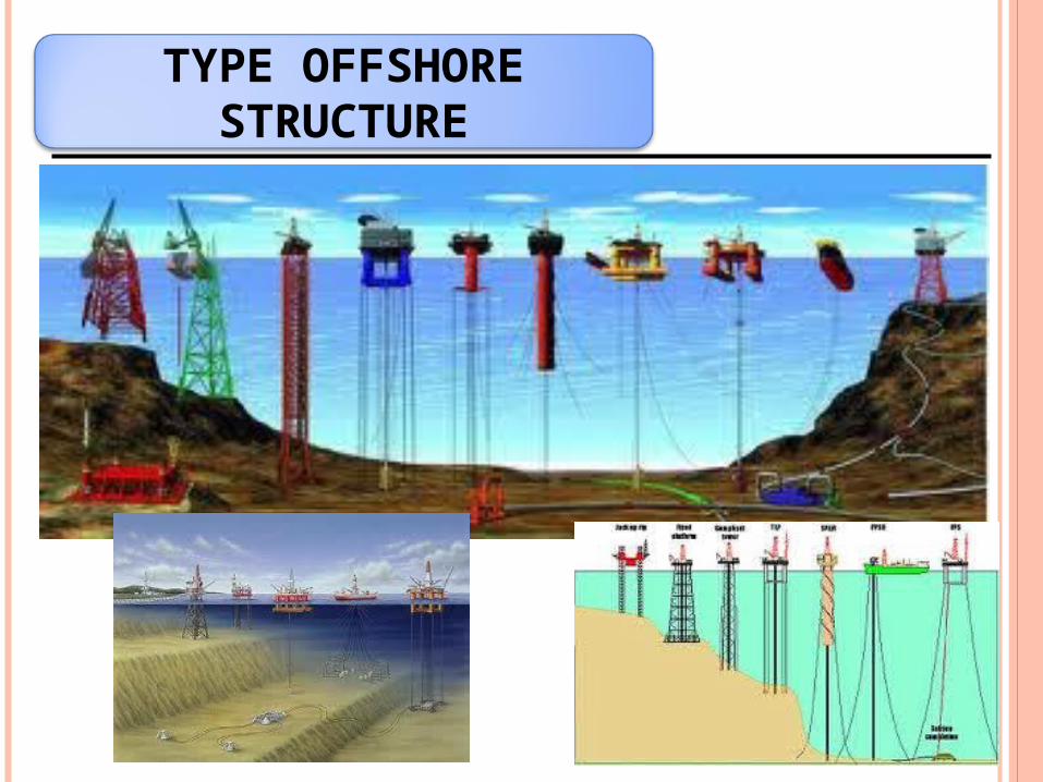
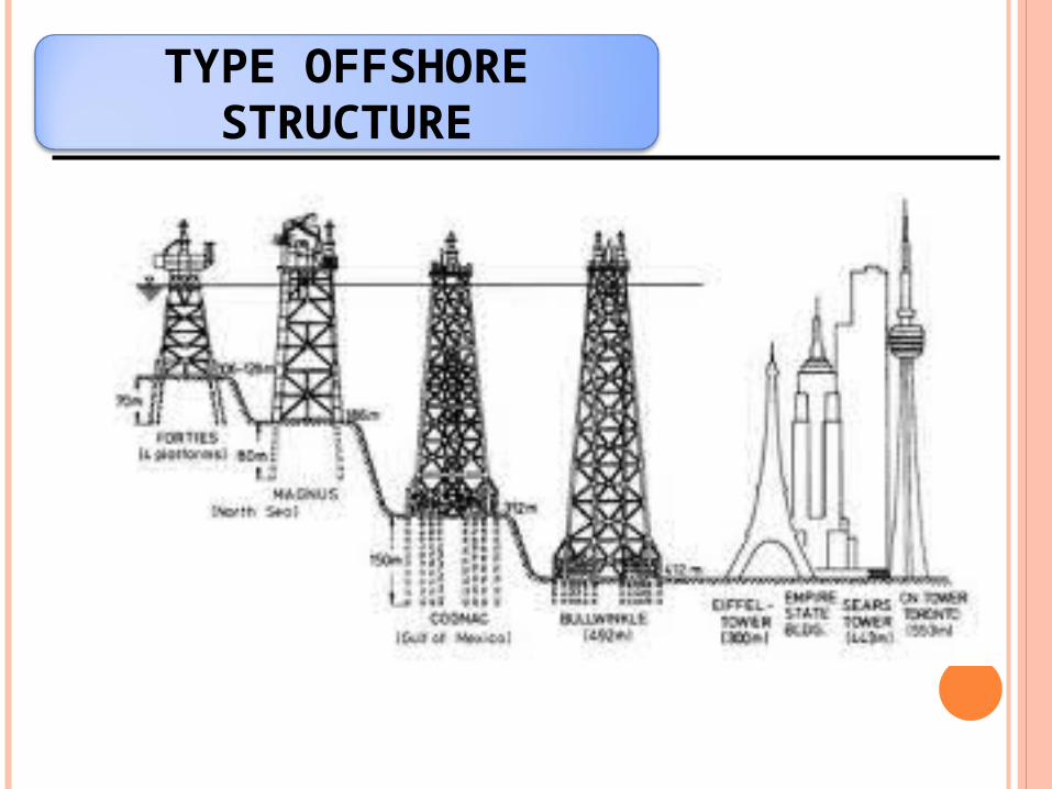
TYPE OFFSHORE STRUCTURE

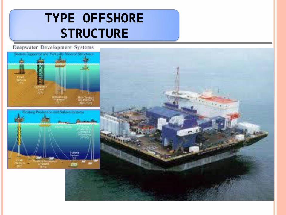
TYPE OFFSHORE STRUCTURE
TYPE OFFSHORE STRUCTURE

TYPE OFFSHORE STRUCTURE
TYPE OFFSHORE STRUCTURE
OFFSHORE PLATFORM DESIGN
Offshore platforms are used for exploration of Oil and Gas from under Seabed and processing.
The First Offshore platform was installed in 1947 off the coast of Louisiana in 6M depth of water.
Today there are over 7,000 Offshore platforms around the world in water depths up to 1,850M
OVERVIEW
Platform size depends on facilities to be installed on top side eg. Oil rig, living quarters, Helipad etc.
Classification of water depths:< 350 M- Shallow water< 1500 M - Deep water> 1500 M- Ultra deep water
US Mineral Management Service (MMS) classifies water depths greater than 1,300 ft as deepwater, and greater than 5,000 ft as ultra-deepwater.
Offshore platforms can broadly categorized in two types.
Fixed structures that extend to the Seabed.Steel JacketConcrete gravity StructureCompliant Tower
Structures that float near the water surface- Recent development
Tension Leg platformsSemi SubmersibleSparShip shaped vessel (FPSO)
OVERVIEW
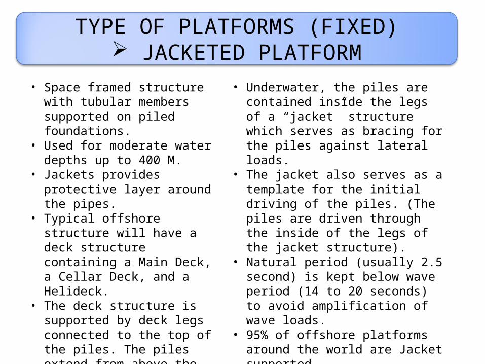
• Space framed structure with tubular members supported on piled foundations.
• Used for moderate water depths up to 400 M.
• Jackets provides protective layer around the pipes.
• Typical offshore structure will have a deck structure containing a Main Deck, a Cellar Deck, and a Helideck.
• The deck structure is supported by deck legs connected to the top of the piles. The piles extend from above the Mean Low Water through the seabed and into the soil.
TYPE OF PLATFORMS (FIXED) JACKETED PLATFORM
• Underwater, the piles are contained inside the legs of a “jacket” structure which serves as bracing for the piles against lateral loads.
• The jacket also serves as a template for the initial driving of the piles. (The piles are driven through the inside of the legs of the jacket structure).
• Natural period (usually 2.5 second) is kept below wave period (14 to 20 seconds) to avoid amplification of wave loads.
• 95% of offshore platforms around the world are Jacket supported.
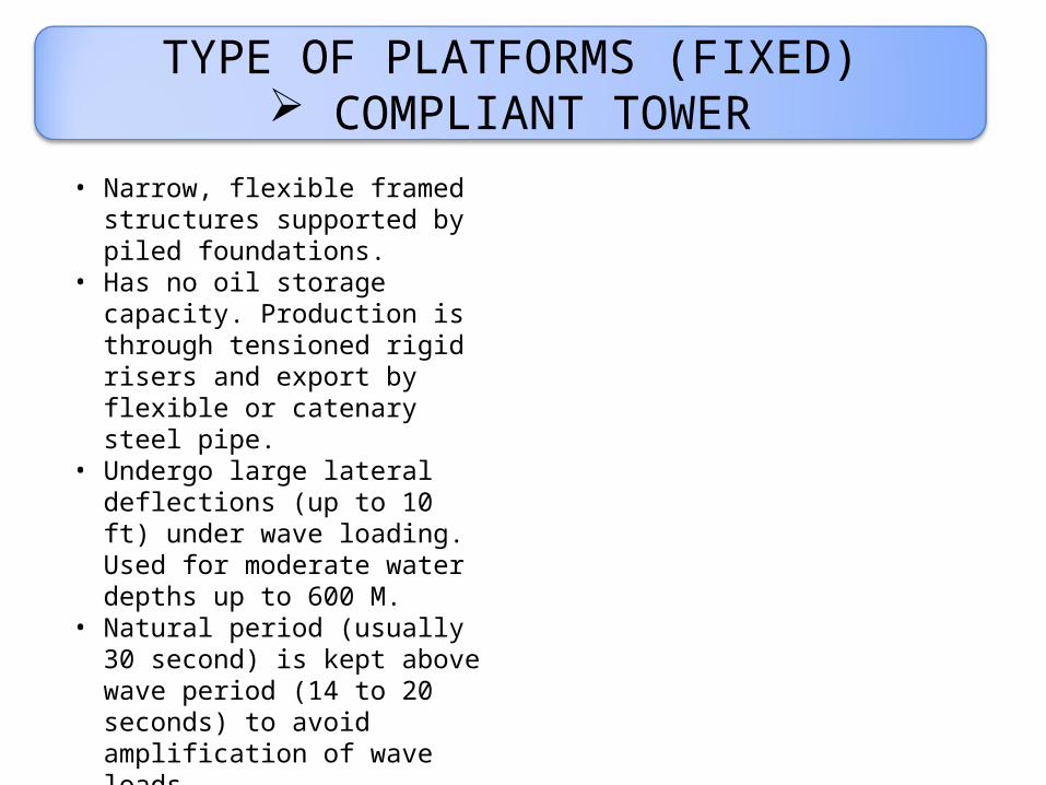
• Narrow, flexible framed structures supported by piled foundations.
• Has no oil storage capacity. Production is through tensioned rigid risers and export by flexible or catenary steel pipe.
• Undergo large lateral deflections (up to 10 ft) under wave loading. Used for moderate water depths up to 600 M.
• Natural period (usually 30 second) is kept above wave period (14 to 20 seconds) to avoid amplification of wave loads.
TYPE OF PLATFORMS (FIXED) COMPLIANT TOWER
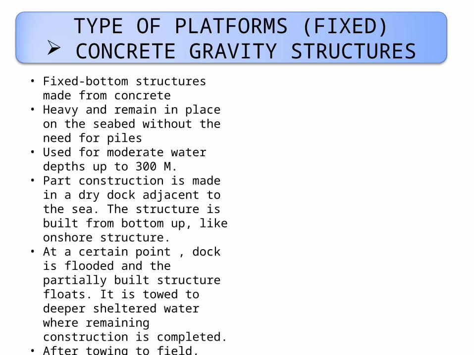
• Fixed-bottom structures made from concrete
• Heavy and remain in place on the seabed without the need for piles
• Used for moderate water depths up to 300 M.
• Part construction is made in a dry dock adjacent to the sea. The structure is built from bottom up, like onshore structure.
• At a certain point , dock is flooded and the partially built structure floats. It is towed to deeper sheltered water where remaining construction is completed.
• After towing to field, base is filled with water to sink it on the seabed.
• Advantage- Less maintenance
TYPE OF PLATFORMS (FIXED) CONCRETE GRAVITY STRUCTURES
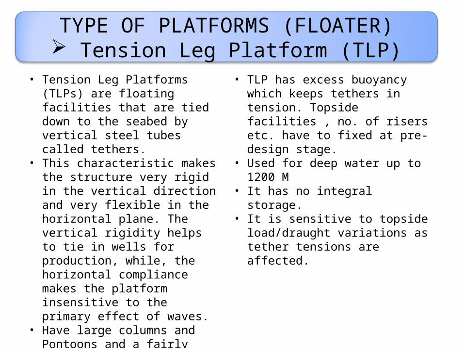
• Tension Leg Platforms (TLPs) are floating facilities that are tied down to the seabed by vertical steel tubes called tethers.
• This characteristic makes the structure very rigid in the vertical direction and very flexible in the horizontal plane. The vertical rigidity helps to tie in wells for production, while, the horizontal compliance makes the platform insensitive to the primary effect of waves.
• Have large columns and Pontoons and a fairly deep draught.
TYPE OF PLATFORMS (FLOATER) Tension Leg Platform (TLP)
• TLP has excess buoyancy which keeps tethers in tension. Topside facilities , no. of risers etc. have to fixed at pre-design stage.
• Used for deep water up to 1200 M• It has no integral storage.• It is sensitive to topside
load/draught variations as tether tensions are affected.
TYPE OF PLATFORMS (FLOATER) SEMISUB PLATFORM
• Due to small water plane area , they are weight sensitive. Flood warning systems are required to be in-place.
• Topside facilities , no. of risers etc. have to fixed at pre-design stage.
• Used for Ultra deep water.• Semi-submersibles are held in
place by anchors connected to a catenary mooring system.
• Column pontoon junctions and bracing attract large loads.
• Due to possibility of fatigue cracking of braces , periodic inspection/ maintenance is prerequisite
• Concept of a large diameter single vertical cylinder supporting deck.
• These are a very new and emerging concept: the first spar platform, Neptune , was installed off the USA coast in 1997 .
• Spar platforms have taut catenary moorings and deep draught, hence heave natural period is about 30 seconds.
• Used for Ultra deep water depth of 2300 M.
• The center of buoyancy is considerably above center of gravity , making Spar quite stable.
• Due to space restrictions in the core, number of risers has to be predetermined.
TYPE OF PLATFORMS (FLOATER) SPAR
• Ship-shape platforms are called Floating Production, Storage and Offloading (FPSO) facilities.
• FPSOs have integral oil storage capability inside their hull. This avoids a long and expensive pipeline to shore.
• Can explore in remote and deep water and also in marginal wells, where building fixed platform and piping is technically and economically not feasible
• FPSOs are held in position over the reservoir at a Single Point Mooring (SPM). The vessel is able to weathervane around the mooring point so that it always faces into the prevailing weather.
TYPE OF PLATFORMS (FLOATER) SHIP SHAPED VESSEL (FPSO)
• Facilities are tailored to achieve weight and space saving
• Incorporates process and utility equipment
1. Drilling Rig2. Injection Compressors3. Gas Compressors4. Gas Turbine Generators5. Piping6. HVAC7. Instrumentation
• Accommodation for operating personnel.
• Crane for equipment handling• Helipad
PLATFORM PARTS TOPSIDE
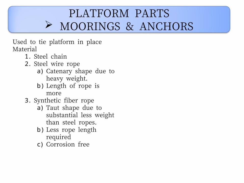
Used to tie platform in placeMaterial
1. Steel chain2. Steel wire rope
a) Catenary shape due to heavy weight.
b) Length of rope is more3. Synthetic fiber rope
a) Taut shape due to substantial less weight than steel ropes.
b) Less rope length requiredc) Corrosion free
PLATFORM PARTS MOORINGS & ANCHORS
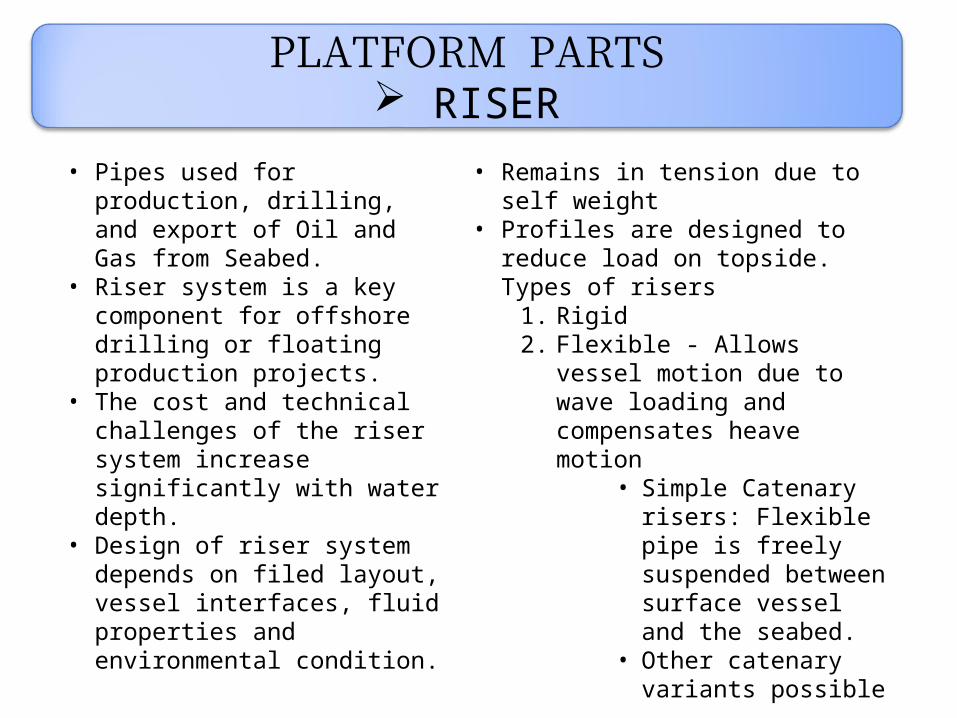
• Pipes used for production, drilling, and export of Oil and Gas from Seabed.
• Riser system is a key component for offshore drilling or floating production projects.
• The cost and technical challenges of the riser system increase significantly with water depth.
• Design of riser system depends on filed layout, vessel interfaces, fluid properties and environmental condition.
PLATFORM PARTS RISER
• Remains in tension due to self weight
• Profiles are designed to reduce load on topside. Types of risers
1. Rigid2. Flexible - Allows vessel motion
due to wave loading and compensates heave motion
• Simple Catenary risers: Flexible pipe is freely suspended between surface vessel and the seabed.
• Other catenary variants possible

Various methods are deployed based on availability of resources and size of structure.
• Barge Crane• Flat over - Top side is
installed on jackets. Ballasting of barge
• Smaller jackets can be installed by lifting them off barge using a floating vessel with cranes .
Large 400’ x 100’ deck barges capable of carrying up to 12,000 tons are available
PLATFORM INSTALLATION BARGE LOADOUT
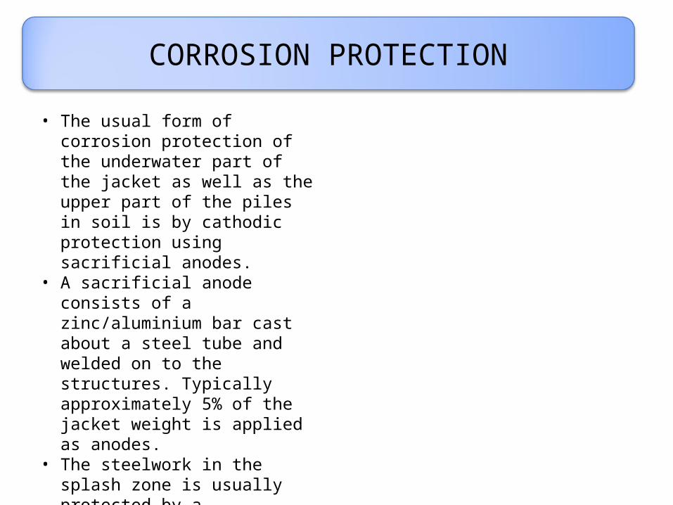
• The usual form of corrosion protection of the underwater part of the jacket as well as the upper part of the piles in soil is by cathodic protection using sacrificial anodes.
• A sacrificial anode consists of a zinc/aluminium bar cast about a steel tube and welded on to the structures. Typically approximately 5% of the jacket weight is applied as anodes.
• The steelwork in the splash zone is usually protected by a sacrificial wall thickness of 12 mm to the members.
CORROSION PROTECTION
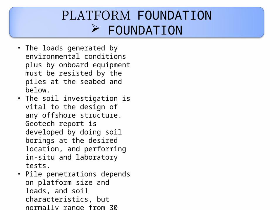
• The loads generated by environmental conditions plus by onboard equipment must be resisted by the piles at the seabed and below.
• The soil investigation is vital to the design of any offshore structure. Geotech report is developed by doing soil borings at the desired location, and performing in-situ and laboratory tests.
• Pile penetrations depends on platform size and loads, and soil characteristics, but normally range from 30 meters to about 100 meters.
PLATFORM FOUNDATION FOUNDATION
• Stability is resistance to capsizing• Center of Buoyancy is located at
center of mass of the displaced water.
• Under no external forces, the center of gravity and center of buoyancy are in same vertical plane.
• Upward force of water equals to the weight of floating vessel and this weight is equal to weight of displaced water
• Under wind load vessel heels, and thus CoB moves to provide righting (stabilizing) moment.
• Vertical line through new center of buoyancy will intersect CoG at point M called as Metacenter
NAVAL ARCHITECTURE HYDROSTATICS AND STABILITY
• Intact stability requires righting moment adequate to withstand wind moments.
• Damage stability requires vessel withstands flooding of designated volume with wind moments.
• CoG of partially filled vessel changes, due to heeling. This results in reduction in stability. This phenomena is called Free surface correction (FSC).
• HYDRODYNAMIC RESPONSE:• Rigid body response• There are six rigid body motions:
1. Translational - Surge, sway and heave
2. Rotational - Roll, pitch and yaw• Structural response - Involving structural
deformations

Loads:Offshore structure shall be designed for following types of loads:
1. Permanent (dead) loads.2. Operating (live) loads.3. Environmental loads
a) Wind loadb) Wave loadc) Earthquake load
4. Construction - installation loads.
5. Accidental loads.
The design of offshore structures is dominated by environmental loads, especially wave load
STRUCTURAL DESIGN

Permanent Loads:Weight of the structure in air, including the weight of ballast.
1. Weights of equipment, and associated structures permanently mounted on the platform.
2. Hydrostatic forces on the members below the waterline. These forces include buoyancy and hydrostatic pressures.
STRUCTURAL DESIGN
Operating (Live) Loads:Operating loads include the weight of all non-permanent equipment or material, as well as forces generated during operation of equipment.
1. The weight of drilling, production facilities, living quarters, furniture, life support systems, heliport, consumable supplies, liquids, etc.
2. Forces generated during operations, e.g. drilling, vessel mooring, helicopter landing, crane operations.
3. Following Live load values are recommended in BS6235:
4. Crew quarters and passage ways: 3.2 KN/m 2
5. Working areas: 8,5 KN/m 2
STRUCTURAL DESIGN

Wind Loads:• Wind load act on portion of platform above
the water level as well as on any equipment, housing, derrick, etc.
• For combination with wave loads, codes recommend the most unfavorable of the following two loadings:
• 1 minute sustained wind speeds combined with extreme waves.
• 3 second gusts .• When, the ratio of height to the least
horizontal dimension of structure is greater than 5, then API-RP2A requires the dynamic effects of the wind to be taken into account and the flow induced cyclic wind loads due to vortex shedding must be investigated.
STRUCTURAL DESIGN
Wave load :• The wave loading of an offshore structure is usually the most important of
all environmental loadings.• The forces on the structure are caused by the motion of the water due to
the waves• Determination of wave forces requires the solution of ,
a) Sea state using an idealization of the wave surface profile and the wave kinematics by wave theory.
b) Computation of the wave forces on individual members and on the total structure, from the fluid motion.
Design wave concept is used, where a regular wave of given height and period is defined and the forces due to this wave are calculated using a high-order wave theory. Usually the maximum wave with a return period of 100 years, is chosen. No dynamic behavior of the structure is considered. This static analysis is appropriate when the dominant wave periods are well above the period of the structure. This is the case of extreme storm waves acting on shallow water structures.
STRUCTURAL DESIGN
Wave Load: (Contd.)Wave theoriesWave theories describe the kinematics of waves of water. They serve to calculate the particle velocities and accelerations and the dynamic pressure as functions of the surface elevation of the waves. The waves are assumed to be long-crested, i.e. they can be described by a two-dimensional flow field, and are characterized by the parameters: wave height (H), period (T) and water depth (d).
STRUCTURAL DESIGN
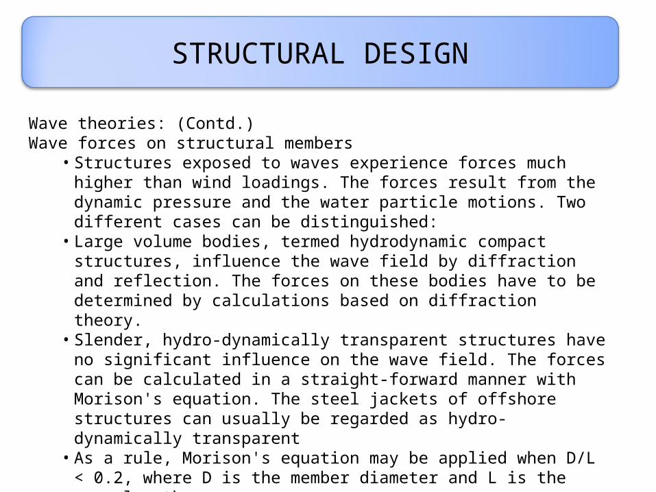
Wave theories: (Contd.)Wave forces on structural members
• Structures exposed to waves experience forces much higher than wind loadings. The forces result from the dynamic pressure and the water particle motions. Two different cases can be distinguished:
• Large volume bodies, termed hydrodynamic compact structures, influence the wave field by diffraction and reflection. The forces on these bodies have to be determined by calculations based on diffraction theory.
• Slender, hydro-dynamically transparent structures have no significant influence on the wave field. The forces can be calculated in a straight-forward manner with Morison's equation. The steel jackets of offshore structures can usually be regarded as hydro-dynamically transparent
• As a rule, Morison's equation may be applied when D/L < 0.2, where D is the member diameter and L is the wave length.
• Morison's equation expresses the wave force as the sum of,•An inertia force proportional to the particle acceleration•A non-linear drag force proportional to the square of the particle velocity.
STRUCTURAL DESIGN
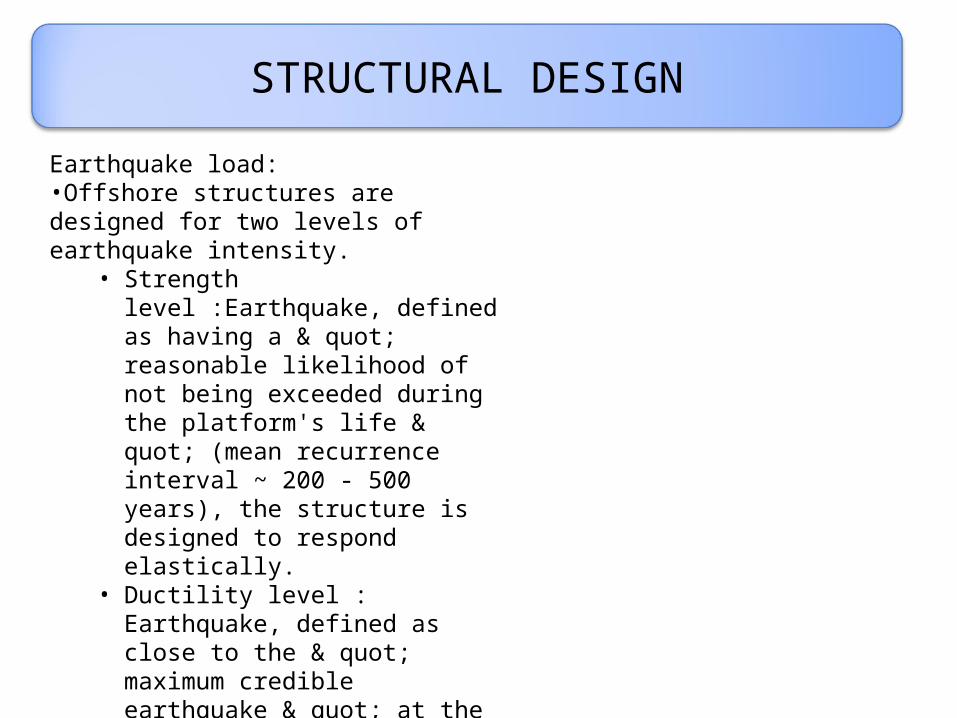
Earthquake load:•Offshore structures are designed for two levels of earthquake intensity.
• Strength level :Earthquake, defined as having a & quot; reasonable likelihood of not being exceeded during the platform's life & quot; (mean recurrence interval ~ 200 - 500 years), the structure is designed to respond elastically.
• Ductility level : Earthquake, defined as close to the & quot; maximum credible earthquake & quot; at the site, the structure is designed for inelastic response and to have adequate reserve strength to avoid collapse.
STRUCTURAL DESIGN
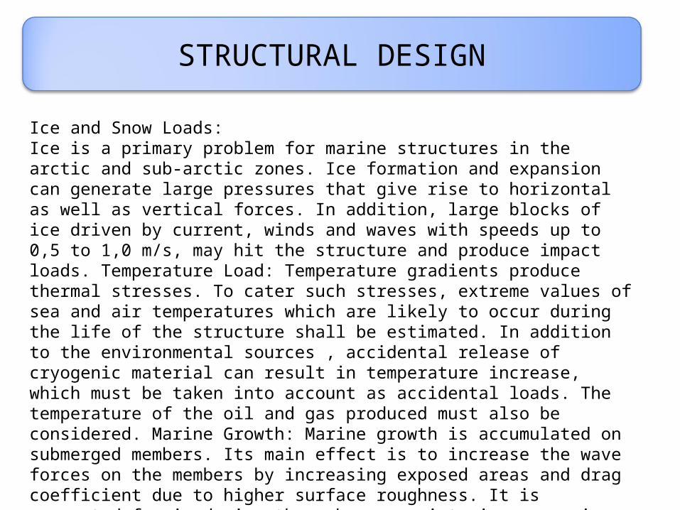
Ice and Snow Loads: Ice is a primary problem for marine structures in the arctic and sub-arctic zones. Ice formation and expansion can generate large pressures that give rise to horizontal as well as vertical forces. In addition, large blocks of ice driven by current, winds and waves with speeds up to 0,5 to 1,0 m/s, may hit the structure and produce impact loads. Temperature Load: Temperature gradients produce thermal stresses. To cater such stresses, extreme values of sea and air temperatures which are likely to occur during the life of the structure shall be estimated. In addition to the environmental sources , accidental release of cryogenic material can result in temperature increase, which must be taken into account as accidental loads. The temperature of the oil and gas produced must also be considered. Marine Growth: Marine growth is accumulated on submerged members. Its main effect is to increase the wave forces on the members by increasing exposed areas and drag coefficient due to higher surface roughness. It is accounted for in design through appropriate increases in the diameters and masses of the submerged members.
STRUCTURAL DESIGN
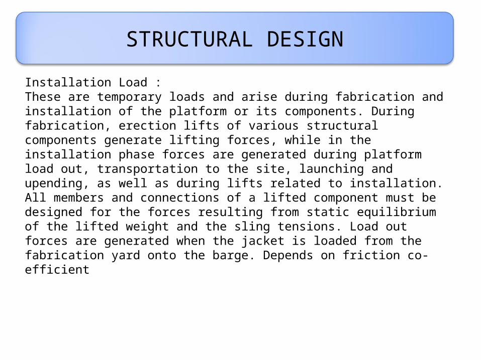
Installation Load : These are temporary loads and arise during fabrication and installation of the platform or its components. During fabrication, erection lifts of various structural components generate lifting forces, while in the installation phase forces are generated during platform load out, transportation to the site, launching and upending, as well as during lifts related to installation. All members and connections of a lifted component must be designed for the forces resulting from static equilibrium of the lifted weight and the sling tensions. Load out forces are generated when the jacket is loaded from the fabrication yard onto the barge. Depends on friction co-efficient
STRUCTURAL DESIGN
Accidental Load :According to the DNV rules , accidental loads are loads, which may occur as a result of accident or exceptional circumstances.Examples of accidental loads are, collision with vessels, fire or explosion, dropped objects, and unintended flooding of buoyancy tanks.Special measures are normally taken to reduce the risk from accidental loads.
STRUCTURAL DESIGN
Load Combinations :The load combinations depend upon the design method used, i.e. whether limit state or allowable stress design is employed.The load combinations recommended for use with allowable stress procedures are:
Normal operationsDead loads plus operating environmental loads plus maximum live loads . Dead loads plus operating environmental loads plus minimum live loads .Extreme operationsDead loads plus extreme environmental loads plus maximum live loads. Dead loads plus extreme environmental loads plus minimum live loads
Environmental loads,should be combined in a manner consistent with their joint probability of occurrence.Earthquake loads, are to be imposed as a separate environmental load, i.e., not to be combined with waves, wind, etc.
STRUCTURAL DESIGN
The analytical models used in offshore engineering are similar to other types of on shore steel structuresThe same model is used throughout the analysis except supports locations.Stick models are used extensively for tubular structures (jackets, bridges, flare booms) and lattice trusses (modules, decks).Each member is normally rigidly fixed at its ends to other elements in the model.In addition to its geometrical and material properties, each member is characterized by hydrodynamic coefficients, e.g. relating to drag, inertia, and marine growth, to allow wave forces to be automatically generated.
STRUCTURAL ANALYSISANALYSIS MODEL
Integrated decks and hulls of floating platforms involving large bulkheads are described by plate elements.Deck shall be able to resist crane’s maximum overturning moments coupled with corresponding maximum thrust loads for at least 8 positions of the crane boom around a full 360° path.The structural analysis will be a static linear analysis of the structure above the seabed combined with a static non-linear analysis of the soil with the piles.Transportation and installation of the structure may require additional analysesDetailed fatigue analysis should be performed to assess cumulative fatigue damageThe offshore platform designs normally use pipe or wide flange beams for all primary structural members.
STRUCTURAL ANALYSISANALYSIS MODEL
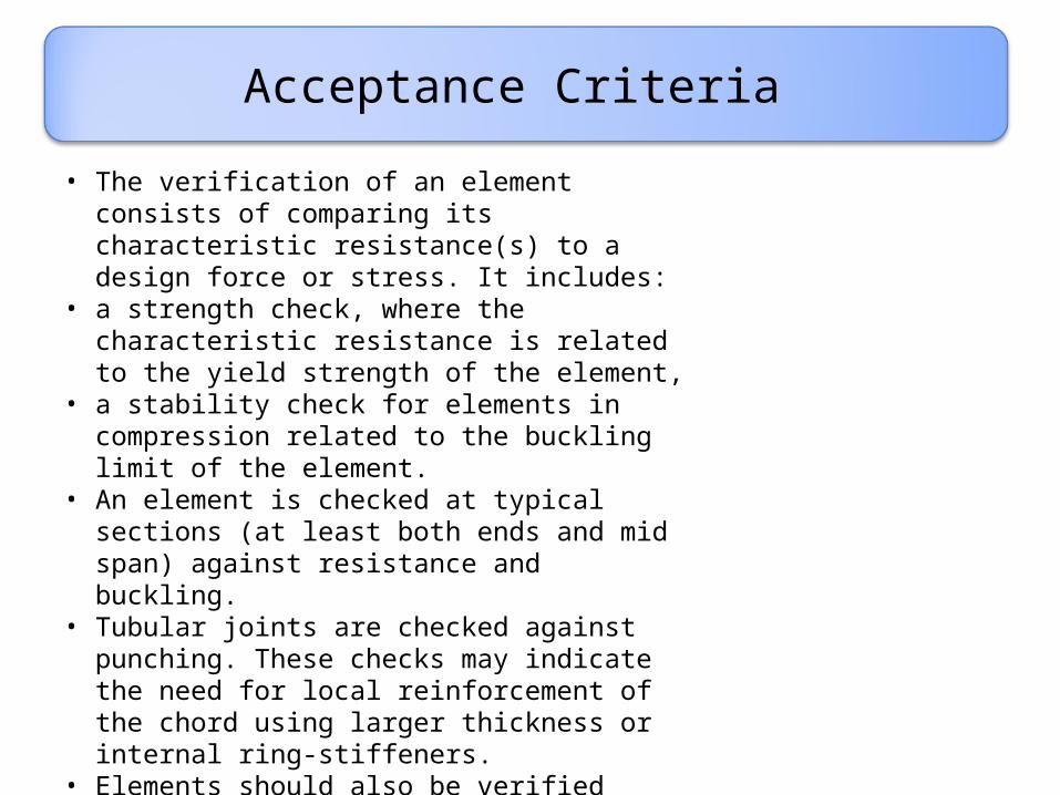
• The verification of an element consists of comparing its characteristic resistance(s) to a design force or stress. It includes:
• a strength check, where the characteristic resistance is related to the yield strength of the element,
• a stability check for elements in compression related to the buckling limit of the element.
• An element is checked at typical sections (at least both ends and mid span) against resistance and buckling.
• Tubular joints are checked against punching. These checks may indicate the need for local reinforcement of the chord using larger thickness or internal ring-stiffeners.
• Elements should also be verified against fatigue, corrosion, temperature or durability wherever relevant.
Acceptance Criteria
Design Conditions:OperationSurvivalTransit.
The design criteria for strength should relate to both intact and damaged conditions.
Damaged conditions to be considered may be like 1 bracing or connection made ineffective, primary girder in deck made ineffective, heeled condition due to loss of buoyancy etc.
STRUCTURAL DESIGN
Offshore Standards (OS):Provides technical requirements and acceptance criteria for general application by the offshore industry eg.DNV-OS-C101
Recommended Practices(RP): Provides proven technology and sound engineering practice as well as guidance for the higher level publications eg. API-RP-WSD
BS 6235: Code of practice for fixed offshore structures.
British Standards Institution 1982.Mainly for the British offshore sector.
CODES
W.J. Graff: Introduction to offshore structures.
• Gulf Publishing Company, Houston 1981.
• Good general introduction to offshore structures.
B.C. Gerwick: Construction of offshore structures.
• John Wiley & Sons, New York 1986.• Up to date presentation of offshore
design and construction.
Patel M H: Dynamics of offshore structures
Butterworth & Co., London.
http://www.slideshare.net/surya3303/offshore-structures-presentation
REFERENCES

Q & A

THANK YOU