Embed Size (px)
Citation preview

1
MAZAGON DOCK SHIPBUILDERS LIMITED (Formerly known as Mazagon Dock Ltd.)
CIN : U35100MH1934GOI002079 (A Government of India Undertaking)
Shipbuilders to the Nation Dockyard Road, Mazagon,
Mumbai 400 010. INDIA
Construction of Concrete/Asphalt Road at North and South Side of Ritchie Dry Dock, MDL,
Mumbai
Technical Specification &
Preferred Make

2
I N D E X
Sr. No.
Description Page Nos.
TECHNICAL SPECIFICATIONS From To
I SECTION – I, TECHNICAL SPECIFICATIONS FOR CIVIL WORKS
4 36
II SECTION – II, SPECIFICATIONS FOR ASPHALTING WORKS
37 63

3
TECHNICAL SPECIFICATIONS
Contents
S.N. Description Page No.
Technical Specification for Civil Work
1. Earth work
4
2. Earth Work in Filling / Refilling 6
3. Hard Core Soling (Trap rubble stone Soling) 7
4. Concrete Work
7
5. Specification for Testing Concrete
20
6. Reinforcement Work
24
7. Ready –Mixed Concrete
26
8. Plastering 29
9. Structural Steel Fabrication and Erection work. 30
10. Painting of Concrete Masonry & Plastered Surface
31
11. Painting of Steel Work 32
12. Applicable Codes and Specifications
33
13. List of Preferred Make
35
Specifications for Asphalting Work
1 Earthwork 37
2 Hard Core Soling (Trap rubble stone Soling) 38
3 Water Bound Macadam Sub-Base/Base 38
4 Tack coat 44
5 Dense Bituminous Macadam 44
6 Bituminous Concrete 50
7 Quality Control for Asphalt Works 54
8 Defective Materials 55
9 Control of Alignment, Level and Surface Regularity 55
10 Rectification 56
11 Quality control test during Construction 57
12 Road marking strips 61
13 Kerb channel of cement concrete 63

4
1. EARTHWORK 1.1. Excavation
1.1.1. The work to be done under this section comprise performance of all work
necessary for excavation with shoring, strutting, dewatering, pumping including disposing of all surplus excavated material from the site as directed by the Engineer.
1.1.2. Excavation shall be carried out in any type of soil, gravel, conglomerate, soft rock,
boulders, old foundation, hard rock, concrete, asphalt or stone paved surfaces old masonry or concrete (plain or reinforced) encountered within width, length and depths indicated in the drawings. Where any temporary or permanent structure like sheet piling, diaphragm wall or piles have already been taken up, all
excavation work shall be from the point carried out earlier and all precaution during further excavation and or any construction operation shall be exercised not to damage such existing temporary or permanent work. Where directed by the Engineer trees encountered within the work site shall be uprooted as per approved
manner and serviceable wooden logs shall be stacked at site / disposed of as directed by the Engineer. Branches of trees etc. shall be disposed of or stacked at site as directed by the Engineer. No permanent work shall be commenced in the excavated area until the foundations pits have been inspected and approved by the
Engineer. The Contractor may use any suitable excavated materials for incorporation in the permanent or temporary works as may be convenient subject to compliance with the specifications. Any obstacles encountered during excavation shall be reported immediately to the Engineer and shall be dealt with
as directed by the Engineer.
1.2. Site Levels 1.2.1. Survey of existing road level by approved survey equipment to establish initial
surface level and finalization of related road work activities. Contractor shall submit level book / Graphic chart for each road section.
1.2.2. Before the work commences the Contractor shall carry out a survey of the levels of the site and obtain verification by the Engineer of these levels. Levels shall be
taken on a grid to be agreed with the Engineer and the Contractor shall submit three prints of the drawing showing the site levels for record purpose.
1.3. Support of Excavation
1.3.1. The Contractor shall adequately support the sides of excavation as may be
necessary to prevent subsidence or movement of the material in which the excavation is being carried out and to ensure the safety of persons and nearby
structures.
1.4. Slips 1.4.1. The Contractor shall take all necessary precautions to prevent slips in excavations
and shall at his own make good any damage or defect and remove to spoil dumps any surplus material caused by slips.
1.5. Excavation beyond Required Limit 1.5.1. Any excavation beyond the required limits and against which concrete is to be
placed shall be made good with concrete of similar grades. Any excavation beyond the required limits at locations where no concrete is to be placed will not be required to be made good with concrete unless otherwise directed by the Engineer
provided always that any consequential additional work caused or necessitated by the excavation beyond limits will not be admitted for payment.

5
1.6. Dewatering 1.6.1. While execution of works, if so encountered, the Contractor shall provide for the
purpose of excavation under water all the necessary dewatering equipment like well points, pumps (including stand byes), pipes, conduits, etc. and make necessary arrangement for proper drainage of the pumped water from the well points and its easy disposal without affecting the site and the adjoining areas. The
Contractor at his own cost shall take any permission required for such disposal of water to other areas, from the respective authorities.
1.7. Earthwork in Filling and Site Clearing 1.7.1. Filling is to be carried out up to the level as shown in the drawing. All old
foundations, boulders etc. encountered during filling shall be removed as directed by the Engineer.
1.8. Soft Patches 1.8.1. All the soft patches encountered at the desired level of excavation, shall be
removed completely as directed by the Engineer and filled back with approved soil and duly rammed and compacted with water to the required density of filling as
specified and to the entire satisfaction of the Engineer. In case of rocky founding strata any soft patch and or voids are encountered, such soft patches shall be replaced and the void filled with plain cement concrete of M-15 grade compacted and finished as per direction and satisfaction of the Engineer.
1.9. Compaction Quality 1.9.1. Compaction of earth and sand filling in areas where foundations and floors are
located, the degree of compaction achieved shall be minimum 95% of maximum
dry density as obtained by Proctor compaction as per IS: 2720 (Part VII). Unless otherwise specified, in roads & other areas the degree of compaction shall be 90%.
1.10. Testing of Filling Layer 1.10.1. After the compaction of each layer, samples shall be taken from the compacted
layer and tested for dry density as per IS Practice. The next layer of filling shall not be permitted to be deposited until the Engineer is satisfied that the previous layer has achieved required compaction. The contractor shall inform the
Engineer in writing for inspection after filling and Compaction of each layer. If any particular layer fails to meet the required compaction, it shall be re-compacted as directed by the Engineer and fresh samples shall be taken to ascertain the compaction density. Such re-compaction shall be continued till the
desired compaction is achieved. The thickness of each compacted layer shall not exceed 200 mm.
1.11. Dressing & Finishing 1.11.1. The filling after it reaches the required level, shall be dressed and finished as
specified to the required alignment, levels, cross sections, dimensions and slopes as shown in the drawing or as directed by the Engineer. No deviation shall generally be allowed from the levels shown in the drawings.
1.12. Surface Excavation 1.12.1. Excavation exceeding 1.5 m in width or / and 10 sq. m. on plan but not
exceeding 30 cm in depth shall be described as 'Surface Excavation`.
6
1.13. Setting Out and Making Profiles 1.13.1. Masonry pillars shall be erected at suitable points in the area, which is visible
from the largest area to serve as benchmarks for the execution of the work.
These benchmarks shall be constructed as required and connected with standard B.M. as approved by the Engineer. Necessary profiles with pegs, bamboos and strings shall be made to show the correct formation levels before the work is started. These shall be maintained during the excavation.
1.14. Classification of Earth Work
1.14.1. The earthwork shall be classified under the following main categories and measured separately for each category.
a) Soil: It includes various types of soils, mud concrete below the ground level.
Shingle and river or nallah bed boulders soling of road, paths and hard core, macadam surface of any description, lime concrete, stone masonry below the
ground level, soft conglomerate and laterite when the stone can be detached from the matrix with picks and shovel.
b) Ordinary Soils, Sand, Clay & Soft Moorum : This includes earth, soft
murrum, top deposits of agricultural soil, reclaimed soil, clay, sand or any combination thereof which can be excavated with shovels, loose application of pick axes etc.
c) Hard soil, murrum, boulders, weathered / soft rock : All decomposed weathered rock, highly fissured rock, old masonry, boulders bigger than 0.03 cum. in volume but not bigger than 0.5 cum. and other varieties of soft rock which can be removed only with hard application pick axes, crow bars,
wedges and hammers with some difficulty. The more fact that the contractor resorts to blasting and / or wedging and chiseling for reasons of his own, shall not mean the rock is classifiable as hard rock.
d) Ordinary Rock : All type of laterite rock will be treated as ordinary rock. If there is any difference of opinion in distinguishing between ordinary and hard rock, then the engineer’s decision shall be final and binding.
Note: The scope of work taking site levels, support the sides of excavation, barricades, dewatering, etc. are inclusive of excavation item, no extra payment will be given to the contractor.
2. Earth Work in Filling / Refilling:
2.1. Unless otherwise specified, selected excavated earth shall be used for refilling. For general area filling for raising formation level selected earth shall be used as directed by the Engineer. Before filling of such area existing top soil shall be scarified to
remove all vegetation and soft or debris already existing. After cleaning of debris etc the top soil shall be compacted before filling with any new soil. In case the filling earth contains deleterious salts it shall not be used. Approval of filling materials is to be obtained well in advance to commencement of work. All clods of earth shall be broken
or removed. Where the excavated material is mostly rock with boulders, the boulders shall be broken into pieces not bigger than 7.5 cm size in any direction mixed with fine materials consisting of decomposed rock, murum or earth so as to fill up the voids as far as possible and then the mixture used for filling, as approved by the
Engineer. However the decision / instructions of the Engineer shall be final.

7
3. Hard Core Soling (Trap rubble stone Soling) 3.1. The hard core shall consist of layers of uniform thickness of trap stone rubble (of size
150 mm to 230 mm) or any other approved stone carefully set as close as possible on
ground properly formed for the purpose. The packing shall consist of large stones. The interstices between the rubble stones shall be filled up with stone chips, spalls, and oversized metal removing the projection of the upper part of the packing so as not to loosen the hard core soling. Also spreading approved hard murrum or soil
collected/stacked during excavation etc, complete, the hard-core soling should be thoroughly rammed, watered, settled to place and made compact.
4. CONCRETE WORK 4.1. General
4.1.1. This section covers the requirements for furnishing of cement concrete including materials proportioning, batching, mixing, testing, placing, compacting, finishing, jointing, curing & all other work as required for cast-in-situ or ready
mixed plain and reinforced concrete.
4.2. Submittals 4.2.1. Materials Reports
a) Prior to start of delivery of materials required for cement concrete the
following shall be submitted by the Contractor to the Engineer for approval. i) Recommended suppliers and / or sources of all ingredients for making
concrete including cement, fine & coarse aggregates, water and additives including samples thereof.
ii) Quality Inspection Plan to ensure continuing quality control of ingredients by periodic sampling, testing and reporting to the Engineer on the quality of materials being supplied.
4.2.2. Plant and Equipment a) The contractor shall submit the proposed programme, methods and details of
plant and equipment to be used for batching, mixing and placing of concrete to the Engineer, well in advance prior to start of work.
4.2.3. Certificates a) With each mix design, the Contractor shall submit test reports on concrete
cubes and as well as on ingredients to be used at the actual construction work for approval of the Engineer.
b) In case the source, brand or characteristic properties of the ingredients are
required to be varied during the term of the contract, a revised mix design report shall be submitted to the Engineer.
4.2.4. Schedules a) The Contractor shall prepare working schedules for dates and quantity,
location of pouring of concrete for each item of work and submit same to the Engineer at least 48 hours before commencement of such work.
4.3. Materials 4.3.1. Before bringing to the site, all materials for cement concrete shall be got approved
by the Engineer. All approved samples shall be retained in the office of the Engineer before placing orders for the materials with suppliers. The materials brought on to the works shall conform in every respect to their approved
samples. 4.3.2. Fresh samples shall be delivered to the Engineer whenever type or source of any
material changes. The contractor shall check each fresh consignment of materials as it is brought on to the works to ensure that they conform to the
specifications and / or approved samples.

8
4.3.3. The Engineer shall have the option to have any of the materials tested to find whether they are in accordance with specifications. All bills, vouchers and test certificates which in the opinion of the Engineer are necessary shall be produced
for his inspection when required. 4.3.4. Any materials which have not been found to conform to the specifications and not
approved by the Engineer shall be removed from the site by the contractor within the time stipulated by the Engineer.
4.4. Cement 4.4.1. The cement used shall be Ordinary Portland Cement conforming to IS: 8112. 4.4.2. Whenever possible all cement of each type shall be obtained each from one
constant source throughout the contract. Cement of different types shall not be mixed with one another. Different brands of cement, or the same brand of cement from different sources, shall not be used without prior notification and approval of Engineer.
4.4.3. The cement shall be supplied either packed in bags or in silos installed for the purpose of supply. Packed cement shall be delivered to the site in original sealed bags which shall be labeled with the weight, date of manufacture, name of manufacturer, brand and type. Cement received in torn bags shall not be used.
Moreover bags of cement which vary in weight by more than 3% shall not be accepted.
4.4.4. All cement shall be fresh when delivered and at ambient atmospheric temperature. 4.4.5. In fair-faced elements, the cement used in the concrete for any complete element
shall be from a single consignment. All cement for exposed concrete shall be from the same approved source and uniform in colour.
4.4.6. With each and every delivery of cement the contractor shall provide the manufacturer's certificate that the cement conforms to the relevant Indian
Standard. 4.4.7. The Contractor shall provide facilities for making 7 days tests and 28 days from
time to time in accordance with IS:3535, IS:4031 and IS:4032 (Latest Edition) and shall allow for carrying out such tests as may be required by the Engineer
and for reporting the results.
4.5. Aggregates 4.5.1. Aggregates from natural sources shall be in accordance with IS: 383. The
Contractor shall submit to the Engineer certificates of grading and compliance from the suppliers for all consignment of aggregate. In addition from time to time, the Contractor shall test that aggregate at site in accordance with IS: 2386 Part I, II & III. The contractor shall allow for and provide all necessary apparatus
for carrying out such tests and for supplying test records to the Engineer. The aggregates shall be free from salts or other harmful chemical impurities.
4.5.2. For fair-faced concrete, the contractor shall ensure that aggregates are free from iron pyrites and impurities, which may cause discoloration.
4.5.3. Fine Aggregates a) The fine aggregate shall be pit sand, river sand or other approved sand
conforming to IS: 383. It shall be free from clay, loam, and earth or vegetable matter & from salt or other harmful chemical impurities. In case impurities
cannot be removed by screening process, sand shall be washed and cleaned to the satisfaction of the Engineer. It shall be clean, sharp, strong, angular and composed of hard silicious material.
i) Silt Content
The maximum quantity of silt in fine aggregates as determined by the Field method shall not exceed 8 percent by volume.

9
4.5.4. Coarse Aggregate a) The coarse aggregate shall be crushed stone conforming to IS: 383, having
nominal size of 20 mm & 40 mm as per requirements and as approved by
Engineer. b) Coarse aggregate obtained from crushed or broken stone shall be angular,
hard, strong, dense, durable, clean and free from soft, friable, thin flat, elongated or flaky pieces.
c) Except where it can be shown to the satisfaction of the Engineer that a supply of properly graded aggregate of uniform quality can be maintained over the period of the works, the grading of aggregate shall be controlled by obtaining the coarse aggregate in different sizes & blending them in correct proportions
as and when required.
4.6. Water 4.6.1. Water used in the works shall be potable water & free from deleterious materials.
Water used for mixing and curing concrete as well as for cooling and / or washing aggregate shall be fresh and clean, free from injurious amounts of oil, salts, acids, alkali, other chemicals and organic matter.
4.6.2. Water shall be from the source approved by the Engineer and shall be in
accordance with IS: 456 (latest edition) 4.6.3. Before starting any concreting work and wherever the source of water changes, the
water shall be tested for its chemical and other impurities to ascertain its suitability for use. No water shall be used until tested, found satisfactory and
approved by Engineer. Water testing kit shall be made available at site for random checking of water.
4.7. Steel Reinforcement
4.7.1. Steel reinforcement shall be of Thermo Mechanically Treated (TMT) bar confirming to IS 1786 (latest edition)
4.8. Admixtures and Additives 4.8.1. Chemical admixtures shall conform to IS 9103 & are not to be used unless
permitted by the Engineer. In case their use is permitted, the type, amount, chemical property and method of use of any admixture proposed by the
contractor shall be submitted to the Engineer for approval prior to the approval of the same.
4.8.2. The contractor shall further provide the following information concerning each admixture to the Engineer.
a) Normal dosage and detrimental effects if any of under dosage and over dosage. b) The chemical names of the main ingredients in the admixture. c) The chloride ion content if any expressed as a percentage by weight of
admixture.
d) Whether or not the admixture leads to entrapment of air when used in the manufacturer's recommended dosage.
e) Where two or more admixtures are proposed to be used in any one mix, the manufacturer's written confirmation of their compatibility.
4.8.3. In reinforced concrete, the chloride ion of any admixture used shall not exceed 2% by weight of the admixture as determined in accordance with IS: 6925 and the total chloride ion in all admixtures used in concrete mix shall not exceed 0.83 percent by weight of cement or as per latest IS code.
4.8.4. The admixtures shall conform to IS: 9103. The suitability of all admixtures shall be verified by trial mixes.

10
4.8.5. The addition of calcium chloride to concrete containing embedded metal will not be permitted under any circumstances.
4.8.6. Retarding admixtures when used shall be based on lingo sulphonates with due
consideration to clause 5.2 and 5.3 of IS: 7861. 4.8.7. Waterproofing admixtures shall comply with IS: 2645.
4.9. Storage All goods and products covered by these specifications shall be procured well in
advance and stored as specified below:
4.9.1. Storage of Cement a) Cement shall be stored on a raised floor in dry, waterproof and well ventilated
shed. b) Cement bags shall be stacked at least 60 cm away from external walls and in
stacks of not more than ten bags to avoid lumping under pressure.
c) Cement stored during monsoons shall be completely enclosed in 700 gauge polythene sheet so arranged that the flap closes on the top stack. The contractor shall ensure that protective polythene sheet is not damaged at any time during use.
d) Cement of different types shall be stored in separate sheds or separate compartment of a shed. If different types of cement are mixed, the Engineer will have the discretion to condemn all the cement concerned.
e) Consignment of cement shall be used in order of delivery. A record shall be
kept of the batch numbers of cement deliveries in such a form that the part of the works in which the cement is used can be readily identified.
f) The contractor shall be responsible for the storage of cement at the site and no claim will be entertained in the event of any damage occurring to cement due to
faulty storage by the contractors or on account of his negligence. g) Cement stored on site for a period longer than eight weeks shall be tested to the
satisfaction of the Engineer before it is used in the works. h) Cement which has so deteriorated in quality that it no longer conforms in all
respects to the requirements of this specification will be condemned by the Engineer & shall not be used in the works. The contractor shall immediately remove from the site all cement, which has been so condemned
4.9.2. Stacking of Aggregates a) Aggregates shall be stored on a suitable well drained raft of concrete, timber,
metal or other approved material. The storage of aggregate on the ground will not be permitted.
b) Each size of aggregate shall be stored separately in such a manner as to prevent spillage and mixing of one aggregate with an adjacent aggregate. The dividing wells of any bins shall be of sufficient height & the aggregate shall be so deposited that a distance of 300 mm shall be left between the top of the
division wall and any part of the aggregate stack. c) When stack piling, the aggregate shall not form pyramids resulting in
segregation of different size particles. The stacks shall be regular and of a height not exceeding two meters.
4.9.3. Stacking and Storage of Steel Reinforcement a) Steel reinforcement shall be stored in a way as to prevent distortion and
corrosion, bars of different classifications, sizes and lengths shall be stored
separately to facilitate issues in such sizes and lengths and to minimize wastage in cutting from standard lengths.
11
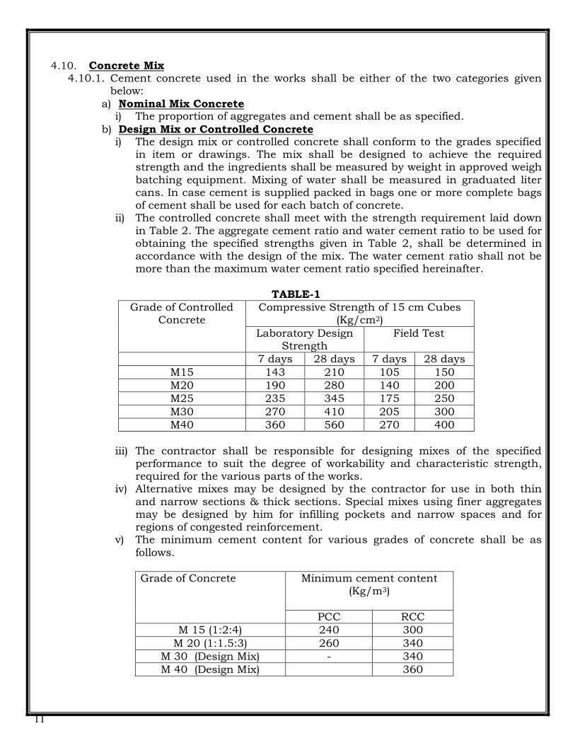
4.10. Concrete Mix 4.10.1. Cement concrete used in the works shall be either of the two categories given
below:
a) Nominal Mix Concrete i) The proportion of aggregates and cement shall be as specified.
b) Design Mix or Controlled Concrete i) The design mix or controlled concrete shall conform to the grades specified
in item or drawings. The mix shall be designed to achieve the required strength and the ingredients shall be measured by weight in approved weigh
batching equipment. Mixing of water shall be measured in graduated liter cans. In case cement is supplied packed in bags one or more complete bags of cement shall be used for each batch of concrete.
ii) The controlled concrete shall meet with the strength requirement laid down
in Table 2. The aggregate cement ratio and water cement ratio to be used for obtaining the specified strengths given in Table 2, shall be determined in accordance with the design of the mix. The water cement ratio shall not be more than the maximum water cement ratio specified hereinafter.
TABLE-1
Grade of Controlled Concrete
Compressive Strength of 15 cm Cubes (Kg/cm2)
Laboratory Design Strength
Field Test
7 days 28 days 7 days 28 days
M15 143 210 105 150
M20 190 280 140 200
M25 235 345 175 250
M30 270 410 205 300
M40 360 560 270 400
iii) The contractor shall be responsible for designing mixes of the specified performance to suit the degree of workability and characteristic strength, required for the various parts of the works.
iv) Alternative mixes may be designed by the contractor for use in both thin
and narrow sections & thick sections. Special mixes using finer aggregates may be designed by him for infilling pockets and narrow spaces and for regions of congested reinforcement.
v) The minimum cement content for various grades of concrete shall be as
follows.
Grade of Concrete Minimum cement content (Kg/m3)
PCC RCC
M 15 (1:2:4) 240 300
M 20 (1:1.5:3) 260 340
M 30 (Design Mix) - 340
M 40 (Design Mix) 360

12
vi) The maximum water cement ratio shall be 0.45 for M-30 & M-25 grade concrete, and 0.5 for M 20 grade concrete
4.10.2. Strength of Nominal Mix Concrete a) The compressive strength on field tests for different nominal mixes, if adopted
are given in Table - 3 below :
Table – 3 Concrete Mix (Nominal) Compressive Strength
(Kg/cm2)
7 days 28 days
M - 15 105 150
M - 20 140 200
4.11. Water Cement Ratio 4.11.1. The quantity of water added to the cement and aggregate during mixing shall be
such as to produce a concrete having sufficient workability to enable it to be properly compacted to be worked into the corners of the shuttering and around reinforcement.
4.11.2. The variation of moisture content within any consignment of aggregate and any
variations due to watering, exposure to rain or drying weather shall be taken into account in determining the quantity of water to be added in concrete mix. The contractor shall carry out regular moisture content tests in accordance with IS:2386 Part III on stacked aggregate as directed by the Engineer and results
submitted to him. 4.11.3. In case of nominal mix concrete the maximum water cement ratio shall be as
stated in Table - 9, IS : 456 and in the case of controlled concrete the water cement ratio shall be as determined in the approved mix design subject to
maximum limit as stated herein before.
4.11.4. The contractor shall exercise tight control on the water content for concrete mix. 4.11.5. When a suitable water cement ratio has been determined and approved by the
Engineer, it shall be maintained throughout the corresponding part of works. Approved tests shall be undertaken periodically by the contractor to satisfy the Engineer of the maintenance of the consistency. However the amount of water added to a mix other than for fair faced concrete may be reduced below the
agreed design amount with the consent of the Engineer if the contractor is able to demonstrate that such a reduction is consistent with producing concrete of the required workability and characteristic strength.
4.11.6. The contractor shall frequently test the concrete for slump cone test. The slump at the actual location of placing as measured in accordance with the methods
laid down in IS:1199 shall not be more than 75 mm and not less than 50 mm unless otherwise approved by the Engineer.
4.12. Approval of Design Mixes 4.12.1. The contractor shall submit to the Engineer for comment sufficient evidence
based on trial mixes that for each grade of concrete, the intended workability, the proposed mix proportions & method of manufactures, which will produce concrete of the required quality.
4.12.2. The contractors shall obtain from the Engineer his written approval on the mix design for each grade of concrete before any concrete of that grade is placed in the works.

13
4.12.3. For each grade of concrete, three separate batches of concrete shall be made by the contractor using materials typical of the proposed supply and under full scale site conditions.
4.12.4. The workability of each of the trial batches shall be determined and 3 specimen preliminary test cubes shall be tested at 7 days & 6 cubes of each set shall be tested at 28 days.
4.12.5. Following agreement with the Engineer on the trial mix proportions should the
contractor wish to make substantial changes in the materials or in the proportions of the materials to be used in mix, the Engineer will require further trial mixes to be made and their results submitted for comments prior to such materials or proportions being adopted by the contractor.
4.13. Concrete Testing
4.13.1. Cube Test a) The strength of concrete either in assessing the suitability of the trial mixes or
when placed in the works shall be determined from 150 mm cubes made, cured, stored, transported and tested in accordance with IS:516 and as specified.
b) Test cubes shall be made as and when required by the Engineer as per the
relevant IS Stipulation. c) Test cubes shall be made under the direct supervision of the competent person
appointed by the contractor to supervise all stages of the preparation and placing of concrete. They shall be made by the contractor in the presence of the
Engineer and generally from concrete taken at the point of discharge from the mixer and the contractor shall provide suitable facilities in the form of a shed or other covered protection as agreed with or directed by the Engineer for the storing and curing of the test cubes during the first 24 hours after making
them and until they are dispatched to the testing laboratory. d) Test cubes shall be marked and dated in such a manner that the trade and the
part of the works in which the concrete they represent has been placed can be readily identified.
e) Testing shall be done in the field laboratory only; in special case with due approval of Engineer or whenever so desired and directed by the Engineer, testing may be carried out in approved laboratory and the results shall be submitted promptly by the contractor to the Engineer without any extra cost.
f) When concrete of a particular grade is first used in the works, 2 cubes each shall be taken from 3 separate batches during each of the first 7 days of using that grade. Of these 6 cubes made daily, 3 cubes (each cube representing concrete made of a different batch) shall be tested at 7 days and the remaining
3 cubes shall be tested at 28 days. g) If the concrete strength determined from such 28 days cube tests does not
reach the characteristic strength for that grade, the materials and / or their proportions for that grade shall be modified by the contractor to the satisfaction
of the Engineer. h) In addition the contractor shall at his own expense take such actions as the
Engineer may consider necessary on the concrete placed in that part of the works represented by the set of cubes so found to be below the characteristic
strength.
4.14. Concrete Production 4.14.1. For production of concrete, concrete batching plant of about 12-15 m3/hr.
capacity with tested and calibrated water meter, mechanical weigh batcher shall be used for production of all concrete. Necessary approval shall be obtained from

14
Engineer before the installation of mixing arrangement is installed at site. However, the contractor, if desires so can procure ready mix concrete from the market at no extra cost subject to compliance of technical specifications as laid
down in the contract agreement for various grade of concrete. Concrete mixer for production of small quantum of concrete and non-structural member can be allowed at the discretion of Engineer.
4.15. Concrete Mixing 4.15.1. All concrete in the correct proportion of ingredients approved by the Engineer,
whether ordinary or controlled, shall be mixed in a batching plant for the minimum time necessary to ensure adequate quality and uniform distribution of
the materials. The cement and aggregates shall normally be first mixed dry until all particles of aggregate are coated with cement after which the water shall be added along with admixture.
4.15.2. Allowance shall be made for the moisture content of the aggregates when
calculating the amount of water to be added for each mix. 4.15.3. The temperature of the aggregate, water and cement when added to the mixer
shall be such that the temperature of the concrete at the time of placement is less than 40oC.
4.15.4. Materials for concrete shall be deposited into the drum while it is in rotation. Mixers shall not be loaded beyond their rated capacity and each batch shall be completely discharged from the drum before recharging takes place.
4.15.5. Facilities shall be provided to spray the mixer drum with cool water between
batches and on the completion of concreting the drum shall be washed thoroughly. The surface of the mixer drum shall be maintained in a clean condition at all times.
4.15.6. Retempering and / or mixing of concrete, which has partially hardened and set
will not be permitted under any circumstances.
4.16. Transporting 4.16.1. The period between mixing the concrete and placing it in the final position shall
be kept to a minimum and the delivery of concrete shall be coordinated with the rate of placement to avoid delays in delivery and placement.
4.16.2. Concrete shall be handled from the place of mixing to the place of final deposit by methods, which prevent segregation, loss of ingredients and contamination and
maintain the required workability. 4.16.3. Should any segregation have occurred in any batches arriving at the place of
deposition, such batches shall be rejected and shall not be allowed to use. Where concrete is conveyed by chutes, the chutes shall be made of metal or fitted with
metal linings. The approval of the Engineer shall be obtained for the use of chutes more than 3 metres long.
4.16.4. All plant and equipment used in the transportation of concrete shall be thoroughly cleaned before and after each working period and at all changes of
concrete mixes. 4.16.5. All major concreting is advisable to be done by concrete pump of adequate
capacity with necessary approval obtained by the contractor. If concrete pump is used, delivery system with adequate boom length, pipeline and associated items
shall be obtained before installation of the concrete pump. There shall also have the provision of a approved standby system in case of any eventualities for transportation and placement of the concrete.

15
4.17. Preparation Before Concreting 4.17.1. The inside surface of the forms against which concrete is to be placed shall be
clean and free from dried or hardened spattering or coatings of concrete. The forms shall be wetted before placing concrete.
4.17.2. When the work has to be resumed on a surface which has hardened, such surface shall be roughened. It shall then be swept clean and covered with a
coating of freshly mixed epoxy based concrete adhesive as per manufacturer's instructions immediately before placing of concrete.
4.17.3. Before any concrete is placed on the sub grade, the sub grade shall be checked and approved for degree of compaction and alignment. The sub grade shall be
kept damp ahead of concreting. 4.17.4. Concrete shall not be placed in the works until the Engineer has inspected the
formwork, reinforcement, inserts and sleeves if any & given his permission to place concrete.
4.18. Placing 4.18.1. Concreting of any portion of the works shall be done only in the presence of the
Engineer or his representative. 4.18.2. Concreting shall be carried out continuously between construction or expansion
joints, shown on the drawings or as agreed with the Engineer. The contractor shall closely follow the sequence of concreting where such is specified in the drawings or instructed at site. If concreting is interrupted before reaching the predetermined joint an approved construction joint shall be provided after
obtaining necessary approval from the Engineer. 4.18.3. Immediately before placing of concrete for columns & walls, the reinforcement
within and the old concrete at the bottom of the formwork shall be given a coating of epoxy based concrete adhesive, to prevent the loss of bonding with
existing surface. 4.18.4. Concrete shall be deposited as nearly as is practicable to its final position and
shall not be dumped in a large quantity at any point to be run or worked along the formwork manually or with vibrators. Concrete shall not be deposited at a
faster rate than it can be placed and compacted. Concrete shall not be placed from a height more than 1.5 m.
4.18.5. Concrete shall be thoroughly worked into the forms so that they are entirely filled, reinforcing bars adequately and tightly surrounded and entrained air
released from the mass of concrete. Placing shall be carried with the use of vibrators in a manner approved by the Engineer.
4.18.6. For members having thickness more than 300 mm, the concrete shall be placed in layers not greater than 300 mm thickness and thoroughly compacted before
succeeding layers are placed. Concrete shall be placed in single operation to the full thickness of slabs, beams and similar members. No concrete shall be placed on concrete which has set sufficiently to cause the formation of planes of weakness & where these are likely to occur due to unforeseen circumstances and
the procedure to be followed shall be as given earlier of this specification. As far as possible, cold joints in concrete shall be avoided.
4.19. Compaction 4.19.1. Each layer of concrete whilst being deposited shall be compacted by approved
methods to form a dense material with all surface free from honeycombing, air holes or other blemishes. The contractor shall use mechanical vibration for all
concrete and shall take care that internal vibrators shall not be brought into contact with the reinforcement or the formwork.

16
4.19.2. An adequate number of vibrators shall be used to ensure that compaction of concrete is achieved within 10 minutes of placing. Particular attention shall be given to the compaction of the concrete around the water bars to ensure that no
voids or porous areas are left. 4.19.3. Compacting shall cease as soon as excess water appears on the face of concrete.
Any water accumulating on the surface of newly placed concrete shall be removed by approved methods and no further concrete shall be placed thereon
until such water has been removed. 4.19.4. Notwithstanding the requirements regarding mix design, should it be found that
the proportion of water in the mix is such that the laitance forms before compaction (i.e. completion of expulsion of air) is complete and unacceptable, the
quantity of water in the mix shall be reduced. Approved admixture / plasticizer shall be used to achieve the necessary workability, as approved by the Engineer and strictly in accordance with manufacturer's instructions. Whenever either of the aforesaid procedures are to be adopted, an additional set of 6 cubes for
testing at 7 or 28 days shall be made from the adjusted mix. 4.19.5. The time elapsed between the discharge of the concrete from the mixer and the
completion of compaction shall not exceed 30 minutes where concrete admixture is not used.
4.19.6. A sufficient number of spare vibrators of various capacities & types shall be kept readily accessible to the place of deposition of concrete to assure adequate vibration in case of breakdown of those in use.
4.20. Finish 4.20.1. All concrete surfaces shall have a good, densed form finish. The top surfaces
specified as smooth shall be leveled and toweled before the concrete begins to set to a smooth finish at levels and falls shown on the drawings. The toweling shall
be done at such a time and in such a manner that excess of mortar is not brought to the surface of concrete nor the aggregate displaced. The top surfaces of concrete slabs specified to receive an integral finish shall be uniformly roughened by deep hacking before the finish is laid
4.20.2. Immediately after striking the formwork and removing any superficial water, honeycombed areas in normal unfinished concrete shall be inspected by the Engineer and where directed the contractor shall immediately make it good to the satisfaction of the Engineer. All air holes shall be similarly filled up.
4.20.3. The contractor shall be responsible for providing an adequate key in concrete where plastering or rendering is specified to be applied. Hacking of the concrete surface after striking the formwork will be permitted only after 3 days after the concreting is done.
4.20.4. The faces of all fair faced concrete shall be of even colour throughout, free from air bubbles, cracks, honeycombing or other blemishes and will be inspected by the Engineer on report by the Contractor, immediately after the formwork has been struck. Such faces shall not be rubbed down or otherwise repaired to
remove any defects or imperfections without the prior permission of the Engineer.
4.20.5. Concrete surface finishes shall accord to the requirements and all instructions by the Engineer with regard to the method of achieving such finishes as
implemented. Wherever directed or specified, concrete surface shall be made broom finished.
17
4.21. Curing and Protection 4.21.1. Walling or further loading on concrete shall not be permitted for at least 48
hours after it has been placed in position, or for such additional length of time as
the Engineer may direct. 4.21.2. Immediately after compaction and completion of any surface finishes, the
concrete shall be protected from the evaporation of moisture by means of polythene sheeting, wet hessian or other suitable material kept soaked by
spraying. As soon as the concrete has attained a degree of hardening sufficient to withstand surface damage, continuous moist curing shall be implemented and maintained for a period of at least 15 days after casting to full satisfaction of the Engineer.
4.21.3. Method of curing and their duration shall be such that the concrete will have satisfactory durability and strength and members will suffer a minimum distortion, be free from excessive efflorescence and will not cause, by its shrinkage, undue cracking in the works.
4.21.4. The top surfaces of slabs and other horizontal surfaces shall be cured by ponding of water in cement mortar bunds. Steeply sloping and vertical formed surfaces shall be kept completely and continuously wet prior to and during the striking of formwork and thereafter by applying adequate water to the top surfaces and
allowing it to pass down between the formwork and the concrete, if required by discharging water through hose pipes and pumps.
4.21.5. The Contractor shall give careful consideration to the curing methods and conditions for fair-faced concrete. Components which are specified to have
exposed concrete finish shall receive the same curing treatment. Moreover water used for curing shall be clean and free from deleterious materials so as not to discolour the concrete.
4.21.6. All fair faced concrete shall be protected from damage at the time of striking the
formwork. All edges and surfaces of such concrete shall be protected from chipping using notched timber or aluminium corner pieces or other suitable covers, which shall be maintained, in place until the completion of the works.
4.21.7. The Contractor shall be responsible for ensuring all fair faced concrete free of
blemishes defect & stains and shall remove all such staining as may occur as soon as possible to the satisfaction of the Engineer.
4.22. Internal Vibrators 4.22.1. These should invariably be used. However, vibrators shall not be used for
displacing concrete. Overloading the vibrators by placing too much concrete per vibrator, over vibrating by using too many vibrators relative to quantity of concrete shall be avoided. Segregation by excessive vibration or excessive water content
should be strictly avoided. Vibrator shall be withdrawn gradually and smoothly, and in a manner which shall not cause suction, voids or air entrapment.
4.23. Construction Joints 4.23.1. Prior to concreting, the Contractor shall submit his proposals giving the position,
form and treatment of such joints to the Engineer for his approval. 4.23.2. Vertical construction joints shall be formed against a stop board of approved
quality and horizontal construction joints shall be level.
4.23.3. Except where shown otherwise on the drawings, reinforcement shall continue through construction joints and stop boards are to be formed to suit such requirements at site.
4.23.4. As soon as possible after the formwork has been struck for vertical joints or after
the concrete has set in horizontal joints, the surface laitance of the hardened concrete on the face of the joint shall be removed to expose the coarse aggregate in

18
such a manner that the loosened particles of aggregate and damaged concrete are not left on the surface. The exposed face shall be swept clean of foreign matter and laitance. Immediately before placing the new concrete, a coat of epoxy based
concrete adhesive shall be put over the old concrete followed for joints of thickness as per manufacturer's instructions.
4.23.5. Before next operation is started, all timber spoils, laitance, scum or loose concrete shall be removed by hacking the surface and then scrubbing off with a wire brush
to remove all loose mortar or aggregates. Thereafter, before resuming concreting operation, the surface should be thoroughly cleaned and a coat of epoxy based conc. adhesive shall be applied. As an additional precaution, approved water bars (as in IS: 3370 (Part-I)-1965) shall be used, if required at such joints as per
manufacturer's instruction. But sufficient care shall be taken when such water barriers are used during pouring concrete from height, so that these strips shall not get bent; and thereby restrict the passage of concrete; causing large size pores and honeycomb concrete. The rate of epoxy based conc. Adhesive is deemed to be
included in the concrete item.
4.24. Expansion Joints 4.24.1. Expansion joints shall be provided where shown on the drawings. They shall be
constructed with an initial gap between the adjoining parts of the works of the width specified in the drawings.
4.24.2. The contractor shall ensure that no debris is allowed to enter and be lodged in expansion joints.
4.24.3. Expansion joints shall be provided with approved joints filler, a joint sealing compound and in waterproof concrete a water bar as specified in drawing.
4.24.4. Joint fillers: a) The joints filler compound shall be easily and uniformly compressible to its
original thickness, tamp able, easily cut or sawn, robust, durable, resistant to decay due to termite or weathering, unaffected by water & free of any constituent which will bleed into or stain the concrete.
b) The joint filler shall be of same thickness of the joint width, it shall extend
through the full thickness of the concrete unless otherwise specified and shall be sufficiently rigid during handling & placing to permit the formation of straight joints.
4.24.5. Joint Sealing Compounds a) Joint sealing compounds shall be in accordance with the IS 3037-1986 and
approved by the Engineer and shall seal joints in concrete against the passage of water, prevent the ingress of grit or other foreign material and protect the joint filler. The compound shall have good extensibility and adhesion to concrete
surfaces and shall be resistant to flow and weathering. b) Where so specified joints shall be sealed with approved polysulphide /
polyurethane, stored, mixed, handled, applied and cured strictly in accordance with the manufacturer's printed instructions. Such joints shall be formed to the
correct dimensions, thoroughly cleaned and treated with recommended primer. The Contractor shall use only competent personnel experienced in the application of sealant for such work.
c) Where specified in the drawings, rubber / bituminous based sealants shall be of
an approved manufacturer. The treatment of the joint and the use of sealing compound shall be strictly in accordance with the manufacturer's printed instructions.
4.25. Cracks

19
4.25.1. If any cracks develop in the reinforced cement concrete construction which in the opinion of the Engineer may be detrimental to the strength of the construction, the contractor shall test the structural element in question. If under these test loads
the cracks shall develop further the contractor shall dismantle the construction, cart away the debris replace the construction and carryout all consequential work thereto.
4.25.2. If the cracks are not detrimental to the stability of the construction in the opinion
of the Engineer, the contractor shall grout the cracks with pneumatically applied mortar or epoxy grout or by other specified treatment as directed by the Engineer at his own expense and risk.
4.25.3. The repair work shall be carried out to the satisfaction of the Engineer. The
decision of the Engineer as to the extent of the liability of the contractor in the above matter shall be final and binding on the contractor.
4.26. Load Testing on Completed Structures 4.26.1. During the period of construction or within the defect liability period as the case
may be, the Engineer may at his discretion order the load testing of any completed structure or any part thereof if he has reasonable doubts about the adequacy of the strength of such structure for any of the following reasons:
a) Unsatisfactory values of the Cube strength of the grade of concrete specified. b) Premature removal of formwork. c) Inadequate curing of concrete. d) Over loading during the construction of the structure or part thereof.
e) Carrying out concreting of any portion without prior approval of the Engineer. f) Honey combed or damaged concrete, which in the opinion of the Engineer is
particularly weak and will affect the stability of the structure to carry the design load, more so in important or critical areas of the structure.
g) Any other circumstances attributable to alleged negligence of the contractor which in the opinion of the Engineer may result in the structure or any part thereof being of less than the expected strength.
4.26.2. All the loading tests shall be carried out by the contractor strictly in accordance
with the instructions of the Engineer. Such tests should be carried out only after expiry of minimum 28 days or such longer period as directed by the Engineer.
4.26.3. The structure should be subjected to a load equal to full dead load plus 1.25 times the imposed load. This load shall be maintained for a period of 24 hours before
removal. During the test, struts strong enough to take the whole load shall be placed in position leaving a gap under the members as directed.
4.26.4. The deflection due to the superimposed load shall be recorded by sufficient number of approved deflectometers capable of reading upto 1/500 of a cm and
located suitably under the structure as directed by the Engineer. If within 24 hours of the removal of the superimposed load, the structure does not recover at least 75% of the deflection under the superimposed load, the test loading shall be repeated after a lapse of 72 hours. If the recovery after the second test is less than
80% of the maximum deflection shown during the second test, the structure shall be considered to have failed to pass the test and shall be deemed to be unacceptable.
4.26.5. If the maximum deflection in mm, shown during 24 hrs. under load is less than
40l2 / D, where l is the effective span in m; and D, the overall depth of the section in mm, it is not necessary for the recovery to be measured and the recovery provisions as stated above.
4.26.6. The part of the work failed in test shall be taken down or cut out and
reconstructed to comply with the specifications. Other remedial measures may be taken to make the structure secure at the discretion of the Engineer. Moreover,

20
such remedial measures shall be carried out to the complete satisfaction of the Engineer.
4.26.7. In addition to the above load tests, non destructive test methods such as core test
and ultrasonic pulse velocity test shall be carried out by the Contractor at his own expense if so desired by the Engineer. Such tests shall be carried out by an agency approved by the Engineer and shall be done under expert guidance using only recommended testing equipment. The acceptance criteria for these tests shall be in
accordance to IS: 1959 and IS:456.
4.27. Non-Destructive Test
4.27.1. If necessitated, the Engineer may ask for Non-Destructive Test for the structural
members under doubt about their strength. None-Destructive Test include Ultrasonic Pulse velocity (IS: 13311, Part-1) & rebound hammer IS: 13311 (Part-2).
4.27.2. All costs involved in carrying out the Load Tests and Non-destructive Test and other incidental expense thereto shall be borne by the contractor regardless of the
result of the tests. The Contractor shall take down or cut out and reconstruct the defective work or shall make the remedial measures instructed at his own cost.
4.28. Supervision 4.28.1. All concreting work shall be done under strict supervision of qualified and
experienced representatives of the Contractor as well as those of the Engineer. The contractor's supervisor who is in charge of concreting work shall be experienced & skilled in this class of work and shall personally supervise all the concreting
operations at all stages.
4.29. Special attention shall be paid to the following 4.29.1. Proportioning, mixing and quality testing of the materials with particular control
on the water cement ratio. 4.29.2. Laying of material in place and thorough compaction of the concrete to ensure
solidity and freedom from voids and honeycombing. 4.29.3. Proper curing for the requisite period.
4.29.4. Reinforcement positions are not disturbed during concreting & consolidation by vibration.
4.30. Quality Control 4.30.1. The Engineer reserves the right to make changes in the mix proportions including
the increased cement content or / and a change in the Contractor's control procedure, should the quality control during progress of the works prove to be inadequate in his opinion and the contractor shall carry out the same. Any extra
cost due to change in mix proportions shall be deemed to have been included in relevant item rates.
4.30.2. All the concrete work shall be true to level, plumb & square within the acceptable tolerance. The corners, edges and rises in all cases shall be unbroken and finished
properly and carefully.
5. SPECIFICATION FOR TESTING CONCRETE 5.1. Cement
5.1.1. The Contractor shall make his own arrangement for procurement of cement. Cement should be of Ultratech, ACC, Gujarat Ambuja or equivalent brand Ordinary Portland cement conforming to IS 8112 – 1989 (Grade 43 or higher).
5.2. Concrete:
21
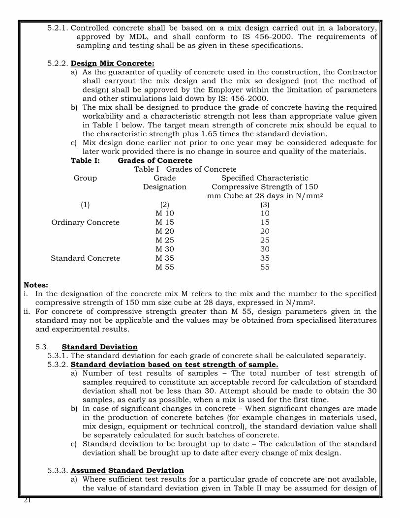
5.2.1. Controlled concrete shall be based on a mix design carried out in a laboratory, approved by MDL, and shall conform to IS 456-2000. The requirements of sampling and testing shall be as given in these specifications.
5.2.2. Design Mix Concrete: a) As the guarantor of quality of concrete used in the construction, the Contractor
shall carryout the mix design and the mix so designed (not the method of
design) shall be approved by the Employer within the limitation of parameters and other stimulations laid down by IS: 456-2000.
b) The mix shall be designed to produce the grade of concrete having the required workability and a characteristic strength not less than appropriate value given
in Table I below. The target mean strength of concrete mix should be equal to the characteristic strength plus 1.65 times the standard deviation.
c) Mix design done earlier not prior to one year may be considered adequate for later work provided there is no change in source and quality of the materials.
Table I: Grades of Concrete Table I Grades of Concrete
Group Grade Designation
Specified Characteristic Compressive Strength of 150
mm Cube at 28 days in N/mm2 (1) (2) (3)
Ordinary Concrete
M 10 10
M 15 15
M 20 20
Standard Concrete
M 25 25
M 30 30
M 35 35
M 55 55
Notes: i. In the designation of the concrete mix M refers to the mix and the number to the specified
compressive strength of 150 mm size cube at 28 days, expressed in N/mm2.
ii. For concrete of compressive strength greater than M 55, design parameters given in the standard may not be applicable and the values may be obtained from specialised literatures and experimental results.
5.3. Standard Deviation 5.3.1. The standard deviation for each grade of concrete shall be calculated separately.
5.3.2. Standard deviation based on test strength of sample. a) Number of test results of samples – The total number of test strength of
samples required to constitute an acceptable record for calculation of standard deviation shall not be less than 30. Attempt should be made to obtain the 30 samples, as early as possible, when a mix is used for the first time.
b) In case of significant changes in concrete – When significant changes are made
in the production of concrete batches (for example changes in materials used, mix design, equipment or technical control), the standard deviation value shall be separately calculated for such batches of concrete.
c) Standard deviation to be brought up to date – The calculation of the standard
deviation shall be brought up to date after every change of mix design.
5.3.3. Assumed Standard Deviation a) Where sufficient test results for a particular grade of concrete are not available,
the value of standard deviation given in Table II may be assumed for design of

22
mix in the first instance. As soon as the results of the samples are available, actual calculated standard deviation shall be used and the mix design properly. However, when adequate past records for a similar grade exist and justify to the
designer a value of standard deviation different from that shown in Table II, it shall be permissible to use that value.
Table II Assumed Standard Deviation
Grade of Concrete Assumed Standard Deviation (N/mm2)
M 10 3.5
M 15
M 20 4.0
M 25
M 30 5.0 M 35
M 40
M 45
M 50
Note: The above values correspond to the site control having proper storage of cement;
weigh batching of all materials; controlled addition of water; regular checking of all materials; aggregate grading and moisture content; and periodical checking of workability and strength. Where there is deviation from the above, the values given in the above Table shall be increased by 1 N/mm2.
5.4. Specimen 5.4.1. Test specimens shall be cubes whose sizes shall be as given below.
Minimum size of Coarse Aggregate Size of specimen cubes in
cm.
Not exceeding 20 mm 10 x 10 x 10
Greater than 20 mm but not exceeding
40 mm
15 x 15 x 15
5.4.2. Sampling of Concrete a) Samples for concrete for test specimens shall be taken at the mixer or in the
case of ready mixed concrete from the transportation vehicle during discharge. The sample of concrete from which test specimens are made shall be representative of the entire batch. Such samples shall be obtained by repeatedly passing a scoop or pail through the discharging stream of concrete,
stacking the sampling operation until the entire batch is discharged. The sample thus obtained shall be transported to the place of moulding of specimen, and to counteract segregation, the concrete shall be mixed with a shovel until it is uniform in appearance. The location in the work of the batch
of concrete thus sampled shall be noted for further reference. In the case of paving concrete, samples may be taken from the batch immediately after deposition on the sub-grade. At least five samples shall be taken from different positions of the pile and these samples shall be thoroughly mixed before being
used to form the test specimens.

23
5.4.3. Preparation of Test Specimens a) The interior surfaces of the mould and base plate shall be lightly oiled before
the concrete is placed in the mould. From the samples of concrete, the test specimen shall be immediately moulded by one of the following methods. i) When the job concrete is compacted by ordinary methods, the 1st
specimen shall be moulded by placing the test concrete in the mould in
layers, each approximately one-third of the volume of the mould. In placing each scoopful of concrete, the scoop shall be moved around the top edge of the mould as the concrete there slides from it, in order to ensure a uniform distribution of concrete within the mould. Each layer shall be
rodded 25 times with a 16 mm rod, 60 cm in length, bullet pointed at the lower end. The strokes shall be distributed in a uniform manner over the cross section of the mould and shall penetrate into the underlying layer. The bottom layer shall be rodded throughout its depth. After the top layer
has been rodded, the surface of the concrete shall be struck off with a trowel and covered with a glass plate at least 6.5 mm thick or a machined metal plate. The whole process of moulding shall be carried out in such a manner as to preclude the alteration of the water cement ratio of the
concrete, by loss of water either by leakage from the bottom or overflow from the top of the mould.
ii) When the job concrete is placed by vibration and the consistency of the concrete is such that the 1st specimen cannot be properly moulded by
hand rodding as directed under (i) above, the specimens shall be vibrated to give a compaction corresponding to that of the job concrete. The fresh concrete shall be placed in the mould in two layers, each approximately half the volume of the mould. In placing each scoopful of concrete, the
scoop shall be moved around the top edge of the mould as the concrete there slides from it, in order to ensure a symmetrical distribution of concrete within the mould. Either internal or external vibrators may be used. The vibration of each layer shall not be continued longer than is
necessary to secure the required density. Internal vibrators shall be of appropriate size and shall penetrate only the layer to be compacted. In compacting the first layer, the vibrators shall not be allowed to rest on the bottom of the mould. In placing the concrete for the top layer, the mould
shall be filled to the extent that there will be no mortar loss during vibration. After vibrating the second layer, enough concrete shall be added to bring the level above the top of the mould. The surface of the concrete shall then be struck off with a trowel and covered with a glass or steel
plate as specified under (a) above. The whole process of moulding shall be carried out in such a manner as to preclude the alteration of the water cement ratio of the concrete, by loss of water either by leakage from the bottom or overflow from the top of the mould.
5.5. Method of Testing 5.5.1. The tests shall be made at the age of the concrete corresponding to that for which
the strengths are specified. 5.5.2. Compression tests shall be made immediately upon removal of the concrete test
specimens from the curing tank i.e. the test specimens shall be loaded in damp condition. The dimensions of the test specimens shall be measured in millimeters
accurate to 0.5 mm.

24
5.5.3. The metal bearing plates of the testing machine shall be placed in contact with the ends of the test specimens. Cushioning materials shall not be used. In the case of cubes, the test specimen shall be placed in the machine in such a manner that
the load is applied to the sides of the specimen as cast. An adjustable bearing block shall be used to transmit the load to the test specimen. The size of the bearing block shall be the same or slightly larger than that of the test specimen. The upper or lower section of the bearing block shall be kept in motion as the
head of the testing machine is brought to a bearing on the test specimen. 5.5.4. The load shall be applied axially without shock at the rate of approximately 140
kg/cm2 per minute. The total load indicated by the testing machine at failure of the test specimen shall be recorded and the unit compressive strength calculated
in kg/sq.cm. Using the area computed from the measured dimensions of the test specimen. The type of failure and appearance of the concrete shall be noted.
5.6. Standard of Acceptance 5.6.1. The standard of acceptance shall be as described below:
a) Three test specimens shall be made for each age at which tests are required. The average of strength of the three specimens may be accepted as the compressive strength of concrete, provided the difference between the
maximum and minimum strengths of the three specimens does not exceed 15% of the average strength. If the difference exceeds 15% of the average strength, repeat tests shall be made unless the minimum strength is greater, than the strength specified.
b) In order to get a relatively quicker idea of the quality of concrete, compressive strength tests at 7 days may be carried out in addition to 28 days compressive strength tests. For this purpose, the values given in Table above may be taken for general guidance in the case of concrete made with ordinary Portland
cement. In all cases, the 28 days compressive strength specified in Table above shall alone be the criterion for acceptance or rejection of the concrete. If, however, from tests carried out in a particular job over a reasonably long period, it has been established to the satisfaction of the Engineer –in-charge
that a suitable ratio between 28 days compressive strength and the 7 days compressive strength exists, the compressive strength at 7 days may be accepted, and the Engineer-in-charge may suitably relax the frequency of 28 days compressive strength specified provided the expected strength values at
the specified early age are consistently met. c) If the average strength of the sample concrete is less than the specified
strength, the work for that day shall be accepted at reduced rate, provided the average strength of sample concrete is not less than 75% of the specified
strength. The Engineer-in-charge shall determine the reduced rate and the quantity of the day’s work for which the rate is to be reduced. If the strength of sample concrete is less than 75% of the minimum specified strength after 28 days, the Engineer-in-charge shall reject the defective portion of the work done
during the day along with the other concrete work structurally affected by the defective portions and get it dismantled.
Note: Six cubes shall be made for a test and 3 out of these shall be tested after 7 days, the remaining 3 cubes shall be tested after 28 days. The result of the 28 days test shall
be taken into account while reducing the rate of rejecting the concrete represented by the sample. The result of the test conducted by the approved testing laboratory shall be taken as final and binding on the Contractor.
6. Reinforcement Work

25
6.1. Steel reinforcement shall be of Thermo Mechanically Treated (TMT) bar confirming to IS 1786 (latest edition)
6.1.1. Bar-Bending Schedules a) The Contractor shall be responsible for preparing, checking all bar bending
schedules against the drawing and obtain approval from the Engineer before cutting and bending and prior to fixing of steel. The Contractor shall remove from site, at his own risk and cost, any steel bar fixed in position, without
obtaining prior approval of bar bending schedule from the Engineer.
6.1.2. Bending and Cutting of Reinforcing Steel Bars a) Reinforcement shall be to the size and shape as shown in drawings and bent
cold, correctly and accurately in accordance with IS: 2502 "Code of Practice for
Bending and Fixing Bars for Concrete Reinforcement". Hooks, L-bends, ties, binding wires & any other subsidiary reinforcement, which are not shown in its correct position, shall be provided by the contractor as per instructions of the Engineer. As far as possible, laps in bars shall be avoided. Any laps and chairs
provided by the contractor other than authorized as per approved bar bending schedule shall be considered to have been provided by the contractor for his own convenience and shall not be measured and paid.
6.1.3. Laps a) Preferably, bars of full length shall be used. Lap of bars, where necessary, shall
be done in accordance with the drawings or as directed by the Engineer and as specified in IS : 456.Wherever facility is available, or there is any requirement, welding of bars may be adopted to in lieu of overlap. The location and type of
welding shall be as approved by the Engineer and as shall be done in accordance with IS:2751.
b) The lapping of bars shall be staggered for different bars and located at points where neither shear nor bending moment is maximum. Hooks, etc. shall be
provided as per Indian Standard Practice and as shown in the drawings.
6.1.4. Chairs etc. a) The Contractor shall provide necessary steel chairs, etc. or other subsidiary
reinforcement which are not shown on the drawings but may be necessary to
keep the reinforcement firmly in its correct position as per the instructions of the Engineer. Hooks, L-bends and laps in bars shall be provided by the Contractor as shown in the drawing and as instructed by the Engineer.
6.1.5. Placing in Position a) Reinforcement bars shall be placed in position as shown in the drawings. The
bars crossing one another shall be tied together at every intersection with two strands of annealed steel wire 0.90 mm (20 SWG) thickness twisted tight to make the skeleton of the steel work rigid so that the reinforcement does not get
displaced during the deposition of concrete. The concrete cover shall not be less than that specified in the drawings. The bars shall be bend and fixed in accordance with the procedure specified in IS: 2502.
b) Tack welding shall also be permitted in lieu of binding with steel wire if approved
by the Engineer. c) The bars shall be kept in position by the following methods.
i) In case of beam and slab construction, precast cover blocks in cement mortar 1:2 (1 cement : 2 coarse sand), about 4 x 4 cm section and of
thickness equal to the specified cover shall be placed between the bars and shuttering, so as to secure and maintain the requisite cover of concrete over reinforcement.
ii) In case of beams with more than one layer of reinforcement at top or bottom
or slabs the vertical distance between the horizontal bars shall be

26
maintained by introducing spacers or support bars of steel at 1.0 meter or at shorter spacing to avoid sagging.
iii) In case of columns and walls, the vertical bars shall be kept in position by
means of timber templates with slots accurately cut in them; or with block of cement mortar (1:2) suitably tied to the reinforcement.
iv) In case of other R.C.C. structure such as arches, domes, etc. cover blocks spacers & templates shall be used as directed by the Engineer.
6.1.6. Storage of Steel Reinforcement a) It shall be stored in such a way as to avoid distortion and to prevent
deterioration and corrosion. Steel reinforcement, shall be stored clear of the ground, on rack or otherwise supported, covered in bundles indicating the type,
number, size, length, diameter and date of delivery to the site of the bars and fabric reinforcement as per IS: 456 and as directed by the Engineer.
6.1.7. Approval of Reinforcement a) The Contractor must obtain the approval of the Engineer to the reinforcement
fixed in position, before concrete is deposited on the shutters.
7. READY-MIXED CONCRETE 7.1. Concrete mixed in a stationary mixer in a central batching and mixing plant or in a
truck-mixer and supplied in the fresh condition to the purchaser either at the site or into the purchaser’s vehicles.
7.2. Approved Plant: Ready mixed concrete conforming to IS 4926: 2003 shall be
supplied from Ultratech, ACC, Godrej, Lafarge RMC plants or other any plants as approved by MDL Engineer in Charge.
7.3. MATERIALS 7.3.1. Selection and Approval of Materials
a) Materials used should satisfy the requirements for the safety, structural performance, durability and appearance of the finished structure, taking fill account of the environment to which it will be subjected. The selection and use
of materials shall be in accordance with IS 456. Materials used shall conform to the relevant Indian Standards applicable. Where materials are used which are not covered by the provisions of the relevant Indian Standard, there should be satisfactory data on their suitability and assurance of quality control. Records
and details of performance of such materials should be maintained. Account should be taken of possible interactions and compatibility between materials used. Also, prior permission of the purchaser shall be obtained before use of such materials.
7.3.2. Cement a) Cement used for concrete shall be in accordance with the requirements of IS
456. b) Mineral Admixtures — Use of mineral admixtures shall be permitted in
accordance with the provisions of Is 456.
7.3.3. Aggregates a) Aggregates used for concrete shall be in accordance with the requirements of
1S 456. Unless otherwise agreed testing frequencies for aggregates shall be as
given in Annex B.
7.3.4. Chemical Admixtures a) Use of chemical admixtures shall be permitted in accordance with the
provisions of IS 456.

27
b) It shall be the responsibility of the producer to establish compatibility and suitability of any admixture with the other ingredients of the mix and to determine the dosage required to give the desired effect.
c) Admixtures should be stored in a manner that prevents degradation of the product and consumed within the time period indicated by the admixture supplier. Any vessel containing an admixture in the plant or taken to site by the producer shall be clearly marked as to its content.
d) When offering or delivering a mix to a purchaser it should be indicated if such a mix contains an admixture or combination of admixtures or not. The admixtures may be identified generically and should be declared on the delivery ticket.
e) The amount of admixture added to a mix shall be recorded in the production record. In special circumstances, if necessary, additional dose of admixture may be added at project site to regain the workability of concrete with the mutual agreement between the producer and the purchaser.
7.3.5. Water a) Water used shall be in accordance with the requirements of IS 456-2000
cl.5.4 b) The use of re-cycled water is encouraged as long as concrete of satisfactory
performance can be produced and steps are taken to monitor the buildup of chlorides in any recirculated water and that any subsequent adjustments to the mix design are made to ensure that any overall limit on chloride contents is satisfied. The addition of any recycled water shall be monitored and controlled
to meet these requirements. c) The total amount of water added to the mix shall be recorded in the production
record. The water content of concrete shall be regulated by controlling its workability or by measuring and adjusting the moisture contents of its
constituent materials. The producer’s production staff and truck-mixer drivers shall be made aware of the appropriate responses to variations in concrete consistence of a particular mix caused by normal variations in aggregate moisture content or grading.
7.4. GENERAL REQUIREMENTS 7.4.1. Basis of Supply
a) Ready-mixed concrete shall be supplied having the quality and in the quantity
in accordance with the requirements agreed with the purchaser or his agent. Notwithstanding this, the concrete supplied shall generally comply with the requirements of 1S456.
b) All concrete will be supplied and invoiced in terms of cubic metres (full or part)
of compacted fresh concrete. All proportioning is to be carried out by mass except water and admixture, which may be measured by volume.
7.4.2. Transport of Concrete a) General
i) Ready-mixed concrete shall be transported from the mixer to the point of placing as rapidly as practicable by methods that will maintain the required workability and will prevent segregation, loss of any constituents
or ingress of foreign matter or water. The concrete shall be placed as soon as possible after delivery, as close as is practicable to its final position to avoid re-handling or moving the concrete horizontally by vibration. If required by the purchaser the producer can utilize admixtures to slow
down the rate of workability loss, however this does not remove the need for the purchaser to place the concrete as rapidly as possible. The

28
purchaser should plan his arrangements so as to enable a full load of concrete to be discharged within 30 min of arrival on site.
ii) Concrete shall be transported in a truck-mixer unless the purchaser
agrees to the use of non-agitating vehicles. When non-agitating vehicles are used, the mixed concrete shall be protected from gain or loss of water.
b) Time in Transport i) The general requirement is that concrete shall be discharged from the
truck-mixer within 2 hrs of the time of loading. However, a longer period may be permitted if retarding admixtures are used or in cool humid weather or when chilled concrete is produced.
ii) The time of loading shall start from adding the mixing water to the dry mix of cement and aggregate or of adding the cement to the wet aggregate whichever is applicable.
iii) Ready-mixed concrete plant shall have test facilities at its premises to
carry out routine tests as per the requirement of the standard.
7.5. SAMPLING AND TESTING OF READY-MIXED CONCRETE 7.5.1. Point and Time of Sampling
a) For the assessment of compliance of ready-mixed concrete, the point and time of sampling shall be at discharge from the producer’s delivery vehicle or from the mixer to the site or when delivered into the purchaser’s vehicle. It is critical that the sampling procedure and equipment used enables as representative a
sample as possible to be taken of the quantity of concrete delivered (see Annex C). The sampling may be carried out jointly by the purchaser and the supplier with its frequency mutually agreed upon. However, it will not absolve the supplier of his responsibility from supplying concrete as per the requirements
given in this standard or otherwise agreed to where so permitted in the standard.
7.5.2. Workability a) The test for acceptance is to be performed upon the producer’s delivery vehicle
discharge on site or upon discharge into the purchaser’s vehicle. If discharge from the producers’ vehicle is delayed on site due to lack of preparedness on behalf of the purchaser then the responsibility passes to the purchaser after a
delay of more than 30 min. The workability shall be within the following limits on the specified value as appropriate:
Slump: ± 25 mm or ± 1/3 of the specified value,
whichever is less. Compacting factor : ± 0.03, where the specified value is 0.90 or
greater, ± 0.04, where the specified value is less
than 0.90 but more than 0.80, and
± 0.05, where the specified value is 0.80 or less.
b) Flow table test may be specified for concrete, for very high workability (see IS
9103). Acceptance criteria for spread (flow) are to be established between the supplier and the purchaser.
7.5.3. Specified Strength

29
a) Compliance shall be assessed against the requirements of IS 456 or other agreed Indian Standard. The purchaser may perform his own sampling and testing or may enter in to an arrangement with the producer to provide his
testing requirements. 7.5.4. Unless otherwise agreed between the parties involved, the minimum testing
frequency to be applied by the producer in the absence of a recognized ready mixed concrete industry method of production control, should be one sample for
every 50 m3of production or every 50 batches, whichever is the greater frequency. Three test specimens shall be made up for each sample for testing at 28 days (see also IS 456).
7.5.5. In order to get a relatively quicker idea of the quality of concrete, optional test on
beams for modulus of rupture at 72 + 2 h or at 7 days or compressive strength test at 7 days maybe carried out in addition to 28 days compressive strength test. For this purpose the value should be arrived at based on actual testing. In all cases 28 days compressive strength shall alone be the criteria for acceptance
or rejection of the concrete. 7.5.6. The purchaser shall inform the producer if his requirements for sampling and
testing are higher than one sample every 50 m3 or 50 batches, whichever is the greater frequency.
7.5.7. Additional Compliance Criteria a) Any additional compliance criteria shall be declared to the producer by the
purchaser prior to supply and shall be mutually agreed upon in terms of
definition, tolerance, frequency of assessment, method of test and significance of result.
8. PLASTERING 8.1. General
8.1.1. Scope a) This section shall cover plastering to masonry wall for storm water drain/cable
trench as shown in the drawings. Before commencing the work sample of works
shall be made in accordance with the specifications indicated below and got approved by the Engineer.
8.1.2. Mortar a) The mortar of specified mix shall be used. Cement and sand shall be tested as
specified in the section on concrete.
8.1.3. Preparation of Surface a) Joints of stonework/brick work shall be raked-out if not done properly at the
time of stonework. Dust and loose mortar shall be brushed out. Efflorescence if
any shall be removed by brushing and scraping. The surface shall be thoroughly washed with water, cleaned and kept wet before plastering is commenced.
b) Plastering work shall be started where all conduits, pipes, fittings and fixtures clamps, hooks, doors and window frames etc. are embedded, grouted and cured
and all defects are removed to the satisfaction of the Engineer. Special approval shall be taken from the Engineer before commencing each plastering work. No cutting of finished plaster shall be allowed under any circumstance. No portion shall be left out initially to be patched up later on.
8.2. Mixing 8.2.1. The ingredients shall be mixed in specific proportions by volume. The mixing shall
be done in a mechanical mixer or by hand mixing on watertight platform. The
cement and sand shall first be mixed thoroughly dry in the mixer. Water shall then be added gradually and wet mixing continued for at least a minute until

30
mortar attains the consistency of a stiff paste and uniform colour. Mortar shall be used within 30 minutes of addition of water. Mortar which has partially set shall not be used and removed from the site immediately.
8.2.2. Wherever specified, waterproofing compound of approved make shall be added to the mortar & mixed strictly in accordance with manufacturer's printed instructions.
9. STRUCTURAL STEEL FABRICATION AND ERECTION WORK 9.1. The structural steel fabrication and erection work will be required wherever the
structural steel members of the workshop shed are rusted beyond repairs and mainly
will consist of crane girders, walkways, bracing and purlins and runners, hand railing and other miscellaneous structures.
9.2. The fabrication and erection of structural steel work shall be in compliance with: 9.2.1. General specifications for structural steel work as per IS: 800.
9.2.2. Necessary drawings to be prepared by the contractor to be got approved through MDL before execution of work.
9.3. The fabrication and erection of steel work shall consist of accomplishing of all jobs including providing all labour, tools and plant, all materials and consumables such as
welding electrodes, bolts and nuts (GKW Quality) Oxygen and Acetylene gases, oils for cleaning, etc., all of approved quality as per the relevant IS Specifications. The work shall be executed according to the drawings, specifications and relevant IS codes in an expeditious and workmanlike manner and of best standard to the complete
satisfaction of the Engineer of MDL. 9.4. All materials shall be new and shall conform to the respective specifications as
specified. The use of equivalent or higher grade or alternative materials will be considered only in very special cases subject to the approval of the Engineer of MDL.
9.5. Structural steel shall conform to IS: 226 or IS: 2062. Steel plates for crane girders shall conform strictly to IS: 2062. Bolts and nuts shall be of GKW Quality and in accordance with IS: 1363.
9.6. The fabrication work shall be done in accordance with IS: 800, in addition to the
following: 9.6.1. The fabrication work shall be done as per the approved fabrication drawings or as
directed. The connections shall be welded or bolted as per the approved drawings or as directed. The work shall include also fabrication of built up
section, if required. Any fault fabrication pointed out at any stage of the work by MDL shall be made good by the contractor at his own cost.
9.6.2. The structural steel member shall be cut mechanically or by oxy-acetylene flame. All edges cut by oxy-acetylene process shall be cleaned of all slag materials prior
to assembly. Edge preparation for welding of members more than 10mm thick shall be done by edge cleaning machine only.
9.6.3. All bolt holes shall be drilled. The drilling shall be made to the diameter specified in the drawings. No enlarging of holes by filling, by man drilling or oxy-acetylene
flame shall be allowed. 9.6.4. The assembly of structural members shall be done with proper jigs and fixtures to
ensure the correct positioning of the members. The first component / assembly fabrication in such jigs and fixtures shall be inspected thoroughly by the
contractor and then offered to the Engineer of MDL for approval before proceeding with the fabrication.
9.6.5. All welding shall be done either manually by the shielded metallic arc process. Welding shall be carried out only by fully trained and experience approved
welders. All welds shall be usually made continuous and watertight. The

31
welding electrodes shall conform to IS:816, low hydrogen type covering or equivalent.
9.7. The erection work in general shall be carried out as required only after approval by
the Engineer of MDL. 9.7.1. All scaffolding work required for the erection work will have to be made by the
contractor and included in the structural steel rate. 9.7.2. Positioning, levelling of the structural members and their alignment shall be done
in accordance with the relevant drawing and to the complete satisfaction of the Engineer of MDL.
9.7.3. The various parts of the steel structure shall be done so erected so as to ensure stability against inherent weight, wind and erection trusses.
9.7.4. All field assembly and welding shall be executed in accordance with the requirement of the relevant fabrication drawings. The bolted joints shall be tightened so that the entire surface of the bolt heads and nuts shall rest on the members. For parts with sloping surfaces tapered washers shall be used.
9.7.5. Any faulty erection done by the contractor shall be made good at his own cost. The contractor shall satisfy himself about the levels, alignment, etc., before starting the erection work.
10. PAINTING OF CONCRETE MASONRY & PLASTERED SURFACES
10.1. MATERIALS 10.1.1. Oil bound distemper shall conform to IS:428. The primer shall be alkali resistant
primer of the same manufacture as that of the distemper. 10.1.2. Cement paint shall conform to IS: 5410. The primer shall be a thinned coat of
cement paint. 10.1.3. Acrylic emulsion paint shall be of an approved manufacture.
10.1.4. Plastic emulsion paint shall conform to IS: 5411. 10.1.5. Lead free acid, alkali and chlorine resisting paint shall conform to IS: 9862. 10.1.6. White wash shall be made from good quality fat lime conforming to IS: 712. It
shall be slaked at site and mixed with water in the proportion of 5 litres of water
to 1 kg of unslaked lime stirred well to make a thin cream. This shall be allowed to stand for a minimum period of one day and strained through a clean coarse cloth. Four kg of gum dissolved in hot water shall be added to each cu.m of cream. 1.30 kg of sodium chloride dissolved in hot water shall then be added per
10 kg of lime used for the white wash to be ready for application. 10.1.7. Colour wash shall be made by addition of a suitable quantity of mineral pigment,
not affected by lime, to the prepared white wash to obtain the shade/tint as approved by the ENGINEER.
10.1.8. All the materials shall be of the best quality from an approved manufacturer. CONTRACTOR shall obtain prior approval of the ENGINEER for the brand of manufacture and the colour/shade. All materials shall be brought to the site of works in sealed containers.
10.2. WORKMANSHIP 10.2.1. CONTRACTOR shall obtain the approval of the ENGINEER regarding the
readiness of the surfaces to receive the specified finish, before commencing the
work on painting. 10.2.2. Painting of new surfaces shall be deferred as much as possible to allow for
thorough drying of the sub-strata. 10.2.3. The surfaces to be treated shall be prepared by thoroughly brushing them free
from dirt, mortar droppings and any loose foreign materials. Surfaces shall be free from oil, grease and efflorescence. Efflorescence shall be removed only by

32
dry brushing of the growth. Cracks shall be filled with Gypsum. Workmanship of painting shall generally conform to IS: 2395.
10.2.4. Surfaces of doors, windows etc. shall be protected suitably to prevent paint
finishes from splashing on them.
MEASUREMENT 10.2.5. Measurement shall be in Sq. M. correct to two places of decimal. Measurement
shall be for the areas as executed duly deducting for any openings etc. Rate quoted shall take into account the provision of necessary enabling works such as scaffolding, painter's cradle etc.
11. PAINTING OF STEEL WORK
11.1. MATERIALS 11.1.1. Red oxide - zinc chrome primer shall conform to IS: 2074.
11.1.2. Synthetic enamel paint shall conform to IS: 2932. 11.1.3. Aluminium paint shall conform to IS: 2339. 11.1.4. All the materials shall be of the best quality from an approved
manufacturer. CONTRACTOR shall obtain prior approval of the ENGINEER for
the brand of manufacture and the colour/shade. All the materials shall be brought to the site in sealed containers.
11.2. WORKMANSHIP 11.2.1. Painting work shall be carried out only on thoroughly dry surfaces. 11.2.2. Painting shall be applied either by brushing or by spraying.
CONTRACTOR shall procure the appropriate quality of paint for this purpose as recommended by the manufacturer. The workmanship shall generally conform
to the requirement of IS:1477 (Part 2). 11.2.3. The type of paint, number of coats etc. shall be as specified in the respective
items of work. 11.2.4. Primer and finish paint shall be compatible with each other to avoid cracking
and wrinkling. Primer and finish paint shall be from the same manufacturer. 11.2.5. All the surfaces shall be thoroughly cleaned of oil, grease, dirt, rust and scale.
The methods to be adopted using solvents, wire brushing, power tool cleaning etc., shall be as per IS: 1477 (Part-1) and as indicated in the item of work.
11.2.6. It is essential to ensure that immediately after preparation of the surfaces, the first coat of red oxide-zinc chrome primer shall be applied by brushing and working it well to ensure a continuous film without holidays. After the first coat becomes hard dry, a second coat of primer shall be applied by brushing to obtain
a film free from 'holidays'. 11.2.7. After the second coat of primer is hard dry, the entire surface shall be wet
rubbed cutting down to a smooth uniform surface. When the surface becomes dry, the undercoat of synthetic enamel paint of optimum thickness shall
be applied by brushing with minimum of brush marks. The coat shall be allowed to hard dry. The under coat shall then be wet rubbed cutting down to a smooth finish, taking adequate care to ensure that at no place the undercoat is completely removed. The surface shall then be allowed to dry.
11.2.8. The first finishing coat of paint shall be applied by brushing and allowed to hard dry. The gloss from the entire surface shall then be gently removed and the surface dusted off. The second finishing coat shall then be applied by brushing.
11.2.9. At least 24 hours shall elapse between the application of successive coats. Each
coat shall vary slightly in shade and this shall be got approved by the ENGINEER.

33
11.2.10. All parts i.e. rail sections (except top surface of rail), sole plates, clamps, stoppers, washers, welded joints, etc., are to be thoroughly cleaned with wire brush and painted with anti-corrosive bitumastic paint of approved make such
as Shalimar, Asian Paint, British Paint, etc.
11.3. MEASUREMENT 11.3.1. Measurement shall be in S q.M. correct to two place of decimal. Measurement
shall be for the projected area between out to out of frames and no multiplying factor is allowed on any account. Rate shall be inclusive of enabling works such as scaffolding, etc. Measurement and payment is applicable only if a separate item is specified and not if it is already made as part of a combined item.
12. APPLICABLE CODES AND SPECIFICATIONS
12.1. The following specifications, standards and codes, including all official amendments/revisions and other specifications & codes referred to therein, should be considered a part of this specification. In all cases the latest issue/edition/revision shall apply. In case of discrepancy between this specification
and those referred to herein below or other specifications forming a part of this bid document, this specification shall govern.
12.2. MATERIALS
12.2.1. IS: 269 - Specification for 33 grade ordinary Portland cement (If specially intended to be used as per drawings/ specifications)
12.2.2. IS: 455 - Specification for Portland slag cement. 12.2.3. IS: 1489 - Specification for portland-pozzolana cement.
12.2.4. IS: 8112 - Specification for 43 grade ordinary Portland cement. 12.2.5. IS:12330- Specification for sulphate resisting Portland Cement 12.2.6. IS:383 - Specification for coarse and fine aggregates from natural sources
for concrete.
12.2.7. IS: 432(Parts I & II) - Specification for mild steel and medium tensile steel bars and hard-drawn steel wires for concrete reinforcement.
12.2.8. IS: 1786 - Specification for high strength deformed steel bars and wires for concrete reinforcement.
12.2.9. IS: 1566 - Specification for hard-drawn steel wire fabric for concrete reinforcement.
12.2.10. IS: 2062 – Steel for general structural purposes. 12.2.11. IS: 9103 - Specification for admixtures for concrete.
12.2.12. IS: 2645 - Specification for integral cement water proofing compounds. 12.2.13. IS: 4990 - Specification for plywood for concrete shuttering work.
12.3. MATERIAL TESTING 12.3.1. IS: 4031(Part 1 to 13) - Methods of physical tests for hydraulic cement. 12.3.2. IS: 4032 - Method of chemical analysis of hydraulic cement. 12.3.3. IS: 650 - Specification for standard sand for testing of cement. 12.3.4. IS: 2430 - Methods for sampling of aggregates for concrete.
12.3.5. IS: 2386(Part 1 to 8) - Methods of test for aggregates for concrete. 12.3.6. IS: 3025 - Methods of sampling and test (physical and chemical) water used in
industry. 12.3.7. IS:6925 - Methods of test for determination of water soluble
34
12.4. MATERIAL STORAGE 12.4.1. IS: 4082 - Recommendations On Stacking And Storing Of Construction
Materials At Site.
12.5. CONCRETE MIX DESIGN
12.5.1. IS: 10262 - Recommended guidelines for concrete mix design.
12.5.2. SP: 23(S&T) - Handbook on Concrete Mixes.
12.6. CONCRETE TESTING 12.6.1. IS: 1199 - Method of sampling and analysis of concrete.
12.6.2. IS:516 - Method of test for strength of concrete 12.6.3. IS:9013 - Method of making, curing and determining compressive strength
of accelerated cured concrete test specimens. 12.6.4. IS: 8142 - Method of test for determining setting time of concrete by
Penetration resistance. 12.6.5. IS:9284 - Method of test for abrasion resistance of concrete 12.6.6. IS: 2770 - Methods of testing bond in reinforced concrete.
12.7. EQUIPMENT 12.7.1. IS: 1791 - Specification for batch type concrete mixers. 12.7.2. IS: 2438 - Specification for roller pan mixer. 12.7.3. IS: 4925 - Specification for concrete batching and mixing plant.
12.7.4. IS: 5892 - Specification for concrete transit mixer and agitator. 12.7.5. IS: 7242 - Specification for concrete spreaders. 12.7.6. IS: 2505 - General Requirements for concrete vibrators: Immersion type. 12.7.7. IS: 2506 - General Requirements for screed board concrete vibrators.
12.7.8. IS: 2514 - Specification for concrete vibrating tables. 12.7.9. IS: 3366 - Specification or pan vibrators. 12.7.10. IS: 4656 - Specification for form vibrators for concrete. 12.7.11. IS: 11993- Code of practice for use of screed board concrete vibrators.
12.7.12. IS: 7251 - Specification for concrete finishers. 12.7.13. IS: 2750 - Specification for steel scaffolding.
12.8. CODES OF PRACTICE 12.8.1. IS: 456 - Code of practice for plain and reinforced concrete. 12.8.2. IS: 3370(Parts I TO IV) - Code of practice for concrete structures for storage of
Liquids. 12.8.3. IS: 3935 - Code of practice for composite construction.
12.8.4. IS: 2502 - Code of practice for bending and fixing of bars for concrete reinforcement.
12.8.5. IS: 5525 - Recommendation for detailing of reinforcement in reinforced concrete works.
12.8.6. IS: 2751 - Code of practice for welding of mild steel plain and deformed bars used for reinforced concrete construction.
12.8.7. Specification for welding cold worked bars for reinforced concrete construction. 12.8.8. IS:3558 - Code of practice for use of immersion vibrators for
consolidating concrete. 12.8.9. IS:3414 - Code of practice for design and installation of joints in Buildings. 12.8.10. IS:4326 - Code of practice for earthquake resistant construction of building. 12.8.11. IS: 13920 – Code of Practice for ductile detailing of reinforced concrete
structures subjected to seismic forces. 12.8.12. IS: 4014(Parts I & II) - Code of practice for steel tubular scaffolding.

35
12.8.13. IS: 2571 - Code of practice for laying in-situ cement concrete flooring. 12.8.14. IS: 7861 - Code of practice for extreme weather concreting. Part-I
Recommended practice for hot weather concreting. Part-II Recommended
practice for cold weather concreting.
12.9. CONSTRUCTION SAFETY
12.9.1. IS: 3696(Parts I & II) - Safety code for scaffolds and ladders. 12.9.2. IS: 7969 - Safety code for handling and storage of building materials. 12.9.3. IS: 8989 - Safety code for erection of concrete framed structures.
12.10. MEASUREMENTS IS:1200 (Part 1 to 23) - Method of measurement of building and engineering works 13. Following are the list of preferred makes to be used in execution of works, if the same are not specified.
LIST OF PREFERRED MAKE:
S.N. DESCRIPTION OF
MATERIAL MAKE OF MATERIALS
1. Cement Ultratech/ ACC / Ambuja / Birla
2.
Steel (Thermo Mechanically Treated Steel) High strength deformed bars or mild steel reinforcement (TOR-Steel)
SAIL, VIZAG, TATA, JSW, RINL, Jindal, Ispat
3. Clay Bricks Good quality locally available material
approved by Engineer / Architect
4. Water proofing material / compound.
Sika / Roff / Sunanda / Krishna Conchem
5. UPVC Pipes ( S/W/R Pipes) Supreme / Finolex / Prince
6. G.I. Pipes ( B-Class) Tata / Zenith
7. G.I. Fittings (ISI Brand) Unik / AMCO
8. S.W. Pipes / Fittings & Gully traps
Perfect / Trimurti / Bharat
9. Ball valves Zoloto
10. C.I. Manhole Cover RIF / BIC / Neco
11. R.C.C. Pipes Indian Hume pipe
12. PVC Fittings (Moulded) Finolex / Prince
13. Non-return valve Intervalve
14. Stoneware Pipe and fittings Trimurti / Perfect Potters / Bharat
15. Stoneware Pipe and fittings Trimurti / Perfect Potters / Bharat
16. Paint Burger/ Nerolac/ Asian/ Dulux/
Tractor.
17. White cement Birla cement, JK cement
18. Putty Birla White Putty

36
S.N. DESCRIPTION OF
MATERIAL MAKE OF MATERIALS
19. Red Oxide Asian
20. Acrylic Exterior paint Asian Ultra/Nitcotex / Sandtex / Berger
Weathershield Note (i) Wherever specification of BOQ item is not mentioned; then CPWD specification shall
be applicable. (ii) Wherever make is specified in BOQ then manufacture’s specifications & procedure
shall be applicable. (iii) Wherever no specifications or make is specified than work is to be carried out as
per the written direction of Engineer-In-Charge

37
SPECIFICATIONS FOR ASPHALTING WORK
Specifications for road work shall be as described under Ministry of Road Transport & Highways (MORTH) and as described under relevant clauses as applicable. 1. EARTHWORK
1.1 Excavation The work to be done under this section comprise performance of all work necessary for excavation with shoring, strutting, dewatering, pumping including disposing of all surplus excavated material from the site as directed by the Engineer.
Excavation shall be carried out in any type of soil, gravel, conglomerate, soft rock, boulders, old foundation, hard rock, concrete, asphalt or stone paved surfaces old masonry or concrete (plain or reinforced) encountered within width, length and depths indicated in the drawings. Where any temporary or permanent structure like sheet piling, diaphragm wall or piles have already been taken up, all excavation work shall be from the point carried out earlier and all precaution during further excavation and or any construction operation shall be exercised not to damage such existing temporary or permanent work. Where directed by the Engineer trees encountered within the work site shall be uprooted as per approved manner and serviceable wooden logs shall be stacked at site / disposed of as directed by the Engineer. Branches of trees etc. shall be disposed of or stacked at site as directed by the Engineer. No permanent work shall be commenced in the excavated area until the foundations pits have been inspected and approved by the Engineer. The Contractor may use any suitable excavated materials for incorporation in the permanent or temporary works as may be convenient subject to compliance with the specifications. Any obstacles encountered during excavation shall be reported immediately to the Engineer and shall be dealt with as directed by the Engineer. 1.2 Site Levels Before the work commences the Contractor shall carry out a survey of the levels of the site and obtain verification by the Engineer of these levels. Levels shall be taken on a grid to be agreed with the Engineer and the Contractor shall submit three prints of the drawing showing the site levels for record purpose.
1.3 Excavation beyond Required Limit Any excavation beyond the required limits and against which asphalt is to be placed shall be made good with bituminous concrete of specified grades. Any excavation beyond the required limits at locations where no Bituminous concrete is to be placed will not be required to be made good with concrete unless otherwise directed by the Engineer provided always that any consequential additional work caused or necessitated by the excavation beyond limits will not be admitted for payment.
1.4 Dewatering While execution of works, if so encountered, the Contractor shall provide for the purpose of excavation under water all the necessary dewatering equipment like well points, pumps (including stand byes), pipes, conduits, etc. and make necessary arrangement for proper drainage of the pumped water from the well points and its easy disposal without affecting the site and the adjoining areas. The Contractor at his own cost shall take any permission required for such disposal of water to other areas, from the respective authorities.

38
1.5 Compaction Quality Compaction of earth where asphalting work is located, the degree of compaction achieved shall be minimum 95% of maximum dry density as obtained by Proctor compaction as per IS: 2720 (Part VII). Unless otherwise specified, in roads & other areas the degree of compaction shall be 90%.
1.6 Classification of soil The earthwork (in the all kinds of soil) shall be classified under the following main categories.
a) Soil includes various types of soils, mud concrete below the ground level, shingle and river or nallah bed boulders, soling of road, paths and hard core, macadam surface of any description, lime concrete, stone masonry below the ground level, soft conglomerate and laterite when the stone can be detached from the matrix with picks and shovel. b) Ordinary Soils, Sand, Clay & Soft Murrum includes earth, soft murrum, top deposits of agricultural soil, reclaimed soil, clay, sand or any combination thereof which can be excavated with shovels, loose application of pick axes etc.
c) Hard soil, murrum, boulders, weathered / soft rock : All decomposed weathered rock, highly fissured rock, old masonry, boulders bigger than 0.03 cum. in volume but not bigger than 0.5 cum. and other varieties of soft rock which can be removed only with hard application pick axes, crow bars, wedges and hammers with some difficulty. The more fact that the contractor resorts to blasting and / or wedging and chiseling for reasons of his own, shall not mean the rock is classifiable as hard rock.
Note: The scope of work taking site levels, support the sides of excavation, barricades, dewatering, etc. are inclusive of excavation item, no extra payment will be given to the contractor.
2. Hard Core Soling (Trap rubble stone Soling) The hard core shall consist of layers of uniform thickness of trap stone rubble (of size
150 mm to 230 mm) or any other approved stone carefully set as close as possible on ground properly formed for the purpose. The packing shall consist of large stones. The interstices between the rubble stones shall be filled up with stone chips, spalls, and oversized metal removing the projection of the upper part of the packing so as not to loosen the hard core soling. Also spreading approved hard murrum or soil collected/stacked during excavation etc., complete, the hard-core soling should be thoroughly rammed, watered, settled to place and made compact.
All above work to be carry out as per MOST specification (latest Edition). 3 WATER BOUND MACADAM SUB-BASE/BASE:
Scope:
This work shall consist of clean, crushed aggregates mechanically interlocked by rolling and bonding together with screening, stone chips, moorum, binding material where necessary and water laid on a properly prepared sub grade / sub-base / base or existing pavement, as the case may be and finished in accordance with the requirements of these specifications and in close conformity with the lines, grades, cross-sections and thickness as per approved plans or as directed by the Engineer.

39
Materials:
3.2.1 Coarse aggregates: Coarse aggregates shall be either crushed or broken stone, The aggregates shall conform to the physical requirements set forth in Table -1. The type and size range of the aggregate shall be specified in the Contract or shall be as specified by the Engineer. If the water absorption value of the coarse aggregate is greater than 2 per cent, the soundness test shall be carried out on the material delivered to site as per IS: 2386 (Part5). 3.2.2 Crushed or broken stone: The crushed or broken stone shall be hard, durable and free from excess flat, elongated, soft and disintegrated particles, dirt and other deleterious material.
TABLE- 1. PHYSICAL REQUIREMENTS OF COARSE AGGREGATES FROR WATER BOUND
MACADAM FOR SUB-BASE/BASE COARSES
Test Test Method Requirements
1 Los Angeles Abrasion Value
IS:2386 (Part-4)
40 per cent (Max)
Aggregate Impact Value IS:2386 (Part-4) or IS:5640
30 per cent (Max)
2. Combined Flakiness and Elongation Indices (Total)
IS:2386 (Part1)
30 per cent (Max)
3.3 Grading requirement of coarse aggregates: The coarse aggregates shall
conform to the grading given in Table 2 as specified, provided, however, the use of Grading No.1 shall be restricted to sub-base courses only.
TABLE -2
GRADING REQUIREMENTS OF COARSE AGGREGATES
Grading No. Size Range IS Sieve
Designation
Per cent by Weight passing
2 90 mm to 45 mm 125 mm 100
90 mm 90-100
63 mm 25-60
45 mm 0-15
22.4 mm 0-5
Note: The compacted thickness for a layer with Grading 2 shall be 120mm.
3.4 Screenings: Screening to fill voids in the coarse aggregate shall generally consist of the same material as the coarse aggregate. However, predominantly non-plastic material such as Moorum or gravel (other than rounded river borne material) may be used for this purpose provided liquid limit and plasticity index of such material are below 20 and 6 respectively and fraction passing 75 micron sieve does not exceed 10 per cent. Screening shall conform to the grading set forth in Table -3. The consolidated details of quantity of screenings required for various grades of stone aggregates are given in
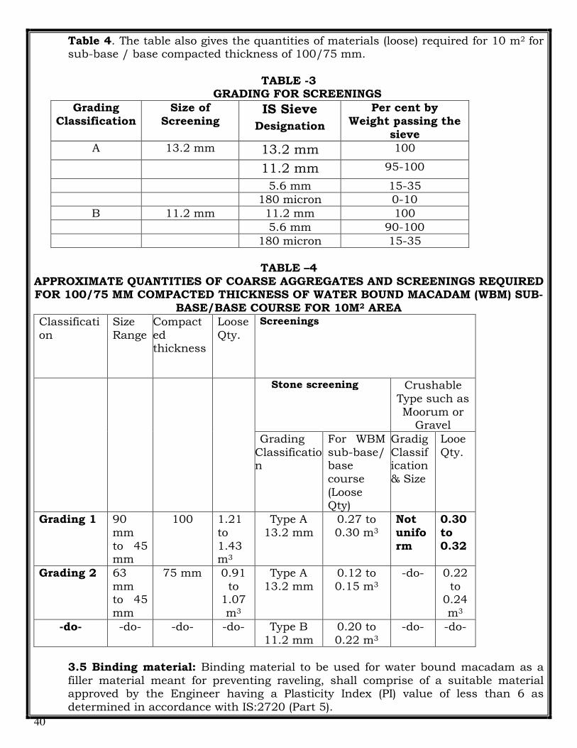
40
Table 4. The table also gives the quantities of materials (loose) required for 10 m2 for sub-base / base compacted thickness of 100/75 mm.
TABLE -3
GRADING FOR SCREENINGS
Grading Classification
Size of Screening
IS Sieve
Designation
Per cent by Weight passing the
sieve
A 13.2 mm 13.2 mm 100
11.2 mm 95-100
5.6 mm 15-35
180 micron 0-10
B 11.2 mm 11.2 mm 100
5.6 mm 90-100
180 micron 15-35
TABLE –4
APPROXIMATE QUANTITIES OF COARSE AGGREGATES AND SCREENINGS REQUIRED FOR 100/75 MM COMPACTED THICKNESS OF WATER BOUND MACADAM (WBM) SUB-
BASE/BASE COURSE FOR 10M2 AREA
Classification
Size Range
Compacted thickness
Loose Qty.
Screenings Stone screening Crushable
Type such as Moorum or
Gravel
Grading Classification
For WBM sub-base/ base course (Loose Qty)
Gradig Classification & Size
Looe Qty.
Grading 1 90 mm to 45 mm
100 1.21 to 1.43 m3
Type A 13.2 mm
0.27 to 0.30 m3
Not uniform
0.30 to 0.32
Grading 2 63 mm to 45 mm
75 mm 0.91 to
1.07 m3
Type A 13.2 mm
0.12 to 0.15 m3
-do- 0.22 to
0.24 m3
-do- -do- -do- -do- Type B 11.2 mm
0.20 to 0.22 m3
-do- -do-
3.5 Binding material: Binding material to be used for water bound macadam as a filler material meant for preventing raveling, shall comprise of a suitable material approved by the Engineer having a Plasticity Index (PI) value of less than 6 as determined in accordance with IS:2720 (Part 5).

41
The quantity of binding material where it is to be used, will depend on the type of screenings. Generally, the quantity required for 75mm and 100mm compacted thickness of water bound macadam will be 0.06-0.09 m3/10 m2 and 0.08-0.10 m3/10 m2 respectively. The above-mentioned quantities should be taken as a guide only, for estimation of quantities for construction, etc. Application of binding materials may not be necessary when the screenings used are of crushable type such as moorum or gravel.
Note: Quantity of coarse aggregate, screening and binding material required for the compacted thickness 120mm WBM should be taken proportionately with respect to clause 3.2 of this specification.
3.6 Construction Operations:
3.6.1 Preparation of base: The surface of the sub-grade/sub-base/base to receive
the water bound macadam course shall be prepared to the specified lines and cross fall (camber) and made free of dust and other extraneous material. Any dust or soft yielding places shall be corrected in an approved manner and rolled until firm surface is obtained if necessary by sprinkling water. Any sub-base/base/surface irregularities, where predominant, shall be made good by providing appropriate type of profile corrective course Specifications.
3.6.2 Spreading coarse aggregates: The coarse aggregates shall be spread uniformly and evenly upon the prepared sub-grade/sub-base/base to proper profile by using templates placed across the road/area about 6m apart, in such quantities that the thickness of each compacted layer is not more than 100mm for Grading 1 and 75mm for Grading 2 and 3, as specified in Table-4. Wherever possible, approved mechanical devices such as aggregate spreader shall be used to spread the aggregates uniformly so as to minimize the need for manual rectification afterwards. Aggregates placed at locations which are inaccessible to the spreading equipment, may be spread in one or more layers by any approved means so as to achieve the specified results. The spreading shall be done from stockpiles along the side of the roadway or directly from vehicles. No segregation of large or fine aggregates shall be allowed and the coarse aggregate, as spread shall be of uniform gradation with no pockets of fine material. The surface of the aggregates spread shall be carefully checked with templates and all high or low spots remedied by removing or adding aggregates as may be required. The surface shall be checked frequently with a straight edge while spreading and rolling so as to ensure a finished surface as per approved drawings. The coarse aggregates shall not normally be spread more than 3 days in advance of the subsequent construction operations.
3.6.3 Rolling: Immediately following the spreading of the coarse aggregate, rolling shall be started with three wheeled power rollers of 8 to 10 tonnes capacity or tandem or vibratory rollers of 8 to 10 tonnes static weight. The type of roller to be used shall be approved by the Engineer based on trial run. Except on super elevated portions where the rolling shall proceed from inner edge to the outer, rolling shall begin from the edges gradually progressing towards the Center. First the edge/edges shall be compacted with roller running forward and backward. The roller shall then move inward parallel to the center line of the road, in

42
successive passes uniformly lapping preceding tracks by at least one half width. Rolling shall be discontinued when the aggregates are partially compacted with sufficient void space in them to permit application of screenings. During rolling, slight sprinkling of water may be done, if necessary. Rolling shall not be done when the sub grade is soft or yielding or when it causes a wave-like motion in the sub grade or sub-base course. The rolled surface shall be checked transversely and longitudinally, with templates and any irregularities corrected by loosening the surface, adding or removing necessary amount of aggregates and re-rolling until the entire surface conforms to desired cross fall (camber) and grade. In no case shall the use of screenings be permitted to make up depressions. Material, which gets crushed excessively during compaction or becomes segregated shall be removed and replaced with suitable aggregates.
3.6.4 Application of screenings: After the coarse aggregate has been rolled as specified in 3.6.3, screenings to completely fill the interstices shall be applied gradually over the surface. These shall not be damp or wet at the time of application. Dry rolling shall be done while the screenings are being spread so that vibrations of the roller cause them to settle into the voids of the course aggregate. The screenings shall not be dumped in piles but be spread uniformly in successive thin layers either by the spreading motions of hand shovels or by mechanical spreaders, or directly from tipper with suitable grit spreading arrangement. Tipper operating for spreading the screenings shall be so driven as not to disturb aggregate. The screenings shall be applied at a slow and uniform rate (in three or more applications) so as to ensure filling of all voids. This shall be accompanied by dry rolling and brooming with mechanical brooms, hand-brooms or both. In no case shall be screenings be applied so fast and thick as to form cakes or ridges on the surface in such a manner as would prevent filling of voids or prevent the direct bearing of the roller on the coarse aggregate. These operations shall continue until no more screenings can be forced into the voids of the coarse aggregate. The spreading, rolling, and brooming of screenings shall be carried out in only such lengths of the road which could be completed within one day’s operation.
3.6.5 Sprinkling of water and grouting: After the screenings have been applied, the surface shall be copiously sprinkled with water have been applied, the surface shall be copiously sprinkled with water, swept and rolled. Hand brooms shall be used to sweep the wet screenings into voids and to distribute them evenly. The sprinkling, sweeping and rolling operation shall be continued, with additional screenings applied as necessary until the coarse aggregate has been thoroughly keyed, well-bonded and firmly set in its full depth and a grout has been formed of screenings. Care shall be taken to see that the base or sub grade does not get damaged due to the addition of excessive quantities of water during construction.
3.6.6 Application of binding material: After the application of screenings as specified in 3.6.4 and 3.6.5, the binding material where it is require to be used (Clause 3.5) shall be applied successively in two or more than layers at a slow and uniform rate. After each application, the surface shall be copiously sprinkled with water, the resulting slurry swept in with hand brooms or mechanical brooms to fill the voids properly, and rolled during which water shall be applied to the wheels of the rollers if necessary to wash down the binding material sticking to them. These

43
operations shall continue until the resulting slurry after filling of voids, forms and wave ahead of the wheels of the moving roller.
3.6.7 Setting and drying: After the final compaction of water bound macadam course, the pavement shall be allowed to dry overnight. Next morning hungry spots shall be filled with screenings or binding material as directed, lightly sprinkled with water if necessary and rolled. No traffic shall be allowed on the road until the macadam has set. The Engineer shall have the discretion to stop hauling traffic from using the completed water bound macadam course, if in his opinion it would cause excessive damage to the surface. The compacted water bound macadam course should be allowed to completely dry and set before the next pavement course is laid over it.
3.7 Reconstruction of defective macadam: The finished surface of water bound macadam shall conform to the tolerance of
surface regularity as prescribed in Table-5. However, where the surface irregularity of the course exceeds the tolerances or where the course is otherwise defective due to sub grade soil mixing with the aggregates, the course to its full thickness shall be scarified over the affected area, reshaped with added material or removed and replaced with fresh material as applicable and re-compacted. In no case shall depressions be filled up with screening or binding material.
TABLE –5 PERMITTED TOLERANCES OF SURFACE EVENNESS FOR WBM COURSES
SI. No.
Size range of coarse
aggregate
Longitudinal profile measured with a 3 meter straight edge
Cross profile
Max. Permissible undulation
Maximum number of undulation
permitted in any 300 meter length exceeding
Max. Permissible variation from specified profile under a camber
template
mm 12mm mm
1 90-45 mm
15 30 12
3.8 Measurements for payment: Water bound macadam shall be measured as finished work in position in cubic
metres.
Rate: The Contract unit rate for water bound macadam sub-base / base course shall be payable in full for carrying out the required operations including full compensation for all components listed in Clause 3.1 to 3.6 including arrangement of water used in the work as approved by the Engineer.
Note: All above work to be carry out as per MOST specification (latest Edition).

44
4 TACK COAT:
4.1 Scope: This work shall consist of application of a single coat of low viscosity liquid bituminous material to an existing road surface/ WBM preparatory to another bituminous construction over it.
4.2. Materials
4.2.1 Binder: The binder used for tack coat shall be bituminous emulsion as specified in the BOQ of the work.
4.3. Construction Operation 4.3.1 Equipment: The tack coat distribution shall be a self propelled or towed
bitumen pressure sprayer, equipped for spaying the material uniformly at a specified rate. Hand spraying the materials uniformly at a specified rate. Hand spraying of small areas, inaccessible to the distributor, or in narrow strips, shall be sprayed with a pressure hand sprayer, or as direction by the Engineer.
4.3.2. Preparation of base: The surface on which the tack coat is to be applied
shall be cleaned of dust, dirt and any extraneous material before the application of the binder, by using a mechanical broom/high pressure air jet or any other approved equipment/method as specified by the Engineer.
4.3.3. Application of tack Coat: Binder may be heated to the temperature appropriate to the grade of cutback used and approved by the Engineer and sprayed on the base at the rate of 0.75 kg per square meter area. The normal range of spraying temperature for a bituminous emulsion shall be 20°C-70°C and for a cutback, 50°C-80°C if RC-70/ MC-70 grade is used. It shall be the responsibility of the Contractor to carefully handle the inflammable bituminous cutback material so as to safeguard against any fire mishap. The binder shall be applied uniformly with the aid of either self-propelled or towed bitumen pressure sprayer with self-heating arrangement and spraying bar with nozzles having constant volume or pressure system, capable of spraying bitumen at specified rates and temperature so as to provide a uniformly unbroken spread of bitumen. Work should be planned so that no more than the necessary tack coat for the day’s operation is placed on the surface. After application and prior to succeeding construction allow the tack coat to cure, without being disturbed, until the water/cutter has completely evaporated, as determined by the Engineer. No vehicles shall be allowed on the tack coat other than those essential for the construction.
4.4 Measurement for Payment: Tack coat shall be measured in terms of surface
area of application in Square Meters. Note: All above work to be carry out as per MOST specification (latest Edition).
5 DENSE BITUMINOUS MACADAM:
5.1 Scope : Dense Bituminous Macadam (DBM) is used mainly for in base/binder and profile corrective courses. DBM is also used as road base material. This work shall consist of construction in a single or multiple layers of DBM on a previously prepared base or sub-base. The thickness of a single layer shall be 50 mm to 100 mm.

45
5.2 Material
5.2.1 Bitumen: The bitumen shall be paving bitumen of penetration Grade of specified consistency and content conforming to IS 73 or as otherwise specified in the item.
5.2.2 Coarse Aggregates: The coarse aggregates shall consist of crushed rock, crushed gravel or other hard material retained on the 2.36 mm IS Sieve. They shall be clean, hard, durable, or cubical shape, free from dust and soft or friable matter, organic or other deleterious substance. Before approval of the source, the aggregates shall be tested for stripping. The aggregates shall satisfy the physical requirements specified in 16.35, for dense bituminous macadam. Where crushed gravel is proposed for use as aggregate, not less than 90% by weight of the crushed material retained on the 4.75 mm IS Sieve shall have at least two fractured faces. 5.2.3 Fine Aggregates: Fine aggregates shall consist of crushed or naturally occurring mineral material, or a combination of the two, passing the 2.36 mm IS Sieve and retained on the 75 micron sieve. They shall be clean, hard, durable, dry and free from dust and soft or friable matter, organic or other deleterious matter. The fine aggregate shall have a sand equivalent value of not less than 50 when tested in accordance with the requirements of IS 2720 (Part 37). The plasticity index of the fraction passing the 0.425 mm IS Sieve shall not exceed 4, when tested in accordance with IS 2720 (Part 5).
TABLE 6
Physical Requirements for Coarse Aggregate for Dense Bituminous Macadam
Property
Test Specification
Cleanliness (dust)
Grain size anlysis1
Max 5% passing 0.075mm sieve.
Particle shape
Flakiness and Elongation Index (Combined)2
Max 30%
Strength* Los Angeles Abrasion Value3 Aggregate Impact Value4
Max 35% Max 27%
Durability Soundness5 Sodium Sulphate Magnesium Sulphate
Max 12% Max 18%
Water Water Max 2%

46
Absorption Absorption6
Stripping Coating and stripping of Bitumen aggregate Mixtures7
Minimum retained coating 95%
Water sensitivity**
Retained Tensile Strength8
Min 80%
Note:
1. IS: 2386 Part 1 2. IS: 2386 Part 1 (The elongation test to be done only on non-aggregate in the sample) 3. IS 2368 Part 4* 4. IS 2368 Part 4* 5. IS 2386 Part 5 6. IS 2386 Part 3 7. IS 6241 8. AASHTO T283** * Aggregate may satisfy requirement of either of these two tests. ** The water sensitivity test is only required if the minimum retained coating in the stripping test is less than 95%.
5.2.4 Filler : Filler shall consist of finely divided mineral matter such as rock dust, hydrated lime or cement approved by the Engineer-in-Charge. The filler shall be graded within the limits indicated in Table 7.
TABLE 7
Grading Requirements for Mineral Filler
Is Sieve (mm) Cumulative per cent passing by weight of total aggregate
0.6 100
0.3 95-100
0.075 85-100
The filler shall be free from organic impurities and have a plasticity index not greater than 4. The Plasticity Index requirements shall not apply if filler is cement or lime. 5.2.5 Aggregate Grading and Binder Content : When tested in accordance with IS 2386 Part 1 (wet sieving method), the combined grading of the coarse and fine aggregates and added filler for the particular mixture shall fall within the limits shown in Table 16-37 for dense bituminous macadam.
TABLE 8
Composition of Dense Graded Bituminous Macadam Pavement Layers
Grading 1

47
Nominal aggregate size 25 mm
Layer Thickness 50-75 mm
IS Sieve1 (mm) Cummulative % by weight of tatal aggregate passing
37.5 100
26.5 90-100
19 71-95
13.2 56-80
4.75 38-54
2.36 28.42
0.3 7-21
0.075 2-8
Bitumen content % by mass of total mix2 (Marshal method)
5% or as specified in the item
Bitumen grade 60/70 grade or as specified in the item
Note: The combined aggregate grading shall not vary from the low limit on one sieve to the high limit on the adjacent sieve.
5.3 Mixture Design 5.3.1 Requirement for the Mixture: The mixture shall meet the requirements as given in Table 9.
TABLE 9
Requirements for Dense Bituminous Macadam
Minimum stability (KN at 600C)
9.0
Minimum flow (mm) 2
Maximum flow (mm) 4
Compaction level (number of blow)
75 blows on each of the two faces of the specimen
Per cent air voids 3-6
Per cent voids in mineral aggregate (VMA)
See Table 10
Per cent voids filled with bitumen (VFB)
65-75
The requirements for minimum percent voids in mineral aggregate (VMA) are given in Table 9.

48
TABLE 10
Minimum Percent Voids in Mineral Aggregate (Vma)
Nominal Maximum Particle
Minimum VMA, Percent Related to Design Air voids, Percent
3.0 4.0 5.0
9.5 14.0 15.0 16.0
12.5 13.0 14.0 15.0
19 12.0 13.0 14.0
25 11.0 12.0 13.0
37.5 10.0 11.0 12.0
Note: 1. The nominal maximum particle size is one size larger than the first sieve to retain more than 10 percent. 2. Interpolate minimum voids in the mineral aggregate (VMA) for design air voids values between those listed. 5.3.2 Binder Content: The binder content shall be optimized by using Marshall method for determining the optimum binder content shall be adopted as described in the Asphalt Institute Manual MS-2, replacing the aggregates retained on the 26.5 mm sieve by the aggregates passing the 26.5 mm sieve and retained on the 22.4 mm sieve. 5.3.3 Job Mix Formula : The contractor shall inform the Engineer-in-Charge in writing, at least 20 days before the start of the work, of the job mix formula proposed for use in the works, and shall give the details of Source and location of all materials, their sizes, grading and test results. Approval of the job mix formula shall be based on independent testing by the Engineer-in-Charge for which samples of all ingredients of the mix shall be furnished by the Contractor as required by the Engineer-in-Charge. Job mix formula shall be revised if there is a change in source of material and be got approved by Engineer-in-Charge. 5.3.4 Plant Trials – Permissible Variation in Job Mix Formula: Once the laboratory job mix formula is approved, the Contractor shall carry out plant trials at the mixer to establish that the plant can be set up to produce a uniform mix conforming to the approved job mix formula. The permissible variations of the individual percentages of the various ingredients in the actual mix from the job mix formula to be used shall be within the limits as specified in Table 16.40.
TABLE 11 Permissible Variations from the Job Mix Formula
Description Permissible Variation
Base/Binder Course Wearing Course
Aggregate passing 19 ± 8% ± 7%

49
mm sieve or larger
Aggregate passing 13.2 mm, 9.5 mm
± 7% ± 6%
Aggregate passing 4.75 mm
± 6% ± 5%
Aggregate passing 2.36 mm, 1.18 mm, 0.6 mm
± 5% ± 4%
Aggregate passing 0.3 mm, 0.15 mm
± 4% ± 3%
Aggregate passing 0.075 mm
± 2% ± 1.5%
Binder content ± 0.3% ± 0.3%
Mixing temperature ± 10°C ± 10°C
5.3.5 Laying Trials: Once the plant trials have been successfully completed and approved, the Contractor shall carry out laying trials, to demonstrate that the proposed mix can be successfully laid and compacted. 5.4 Construction Operations 5.4.1 Prime Coat: Where the material on which the dense bituminous macadam is to be laid is other than a bitumen bound layer, a prime coat shall be applied, as specified, in accordance with the provisions, or as directed by the Engineer-in-Charge. 5.4.2 Tack Coat: Where the material on which the dense bituminous macadam is to be placed is bitumen bound surface, a tack coat shall be applied as specified, in accordance with the provisions, or as directed by the Engineer-in-Charge. 5.4.3 Mixing and Transportation of the Mixture: The provisions are as specified in item and MORTH specification. 5.4.4 Spreading: MORTH specification shall apply. The paver finisher shall be fitted with electronic sensor device. 5.4.5 Rolling: The compaction process shall be carried out as per MORTH Specification. 5.4.6 Opening to Traffic: The newly laid surface shall not be open to traffic for at least 24 hours after laying the completion of compaction, without the express approval of the Engineer-in-Charge in writing. 5.4.7 Surface Finish and Quality Control of Work: The surface finish of the completed construction shall conform to the requirements of 16.32.3. The materials and workmanship shall comply with the provisions set out in Table. 5.4.8 Arrangement for Traffic: During the period of construction, arrangements for traffic shall be made in accordance with the provisions.

50
Measurement Dense Bituminous Materials shall be measured as finished work in cubic meters, correct to two places of decimal. Rate: The rate includes the cost of all materials, labour and equipment, in all the operation described above.
6 BITUMINOUS CONCRETE.
6.1. Scope: This clause specifies the construction of Bituminous Concrete, for use in wearing and profile corrective courses. This work shall consist of construction in a single or multiple layers of bituminous concrete on a previously prepared bituminous bound surface. A single compacted layer shall be 40mm in thickness. 6.2. Materials: 6.2.1. Bitumen: The bitumen shall be paving bitumen of Penetration grade as specified in the BOQ of the work and complying with Indian Standard Specification for Paving Bitumen, IS:73 and of the penetration indicated in Table-8, for bituminous concrete, or as otherwise specified in the Contract
TABLE 12 COMPOSITION OF BITUMINOUS CONCRETE PAVEMENT LAYERS
Grading 1 2
Nominal aggregate size 19mm 13mm
Layer Thickness 50-65mm 30-45mm
IS Sieve1 (mm) Cumulative % by weight of total aggregate passing
45
37.5
26.5 100
19 79-100 100
13.2 59-79 79-100
9.5 52-72 70-88
4.75 35-55 53-71
2.36 28-44 42-58
1.18 20-34 34-48
0.6 15-27 26-38
0.3 5-13 12-20
0.075 2-8 4-10
Bitumen content % by mass of total mix2
5.0-6.0 5.0-7.0
Bitumen grade (pen) As specified in item specification of BOQ or as directed by Engineer In-charge
As specified in item specification of BOQ or as directed by Engineer In-charge

51
Notes: 1. The combined aggregate grading shall not vary from the low limit on one sieve to the high limit on the adjacent sieve.
2. Determined by the Marshall method.
6.2.2. Coarse aggregates: The course aggregates shall be generally as specified in Clause 4.3, except that the aggregates shall satisfy the physical requirements of Table 13.
TABLE 13
PHYSICAL REQUIREMENTS FOR COARSE AGGREGATE FOR BITUMINOUS CONCRETE PAVEMENT LAYERS.
Property Test Specification
Cleanliness (dust)
Grain size analysis Max 5% passing 0.075 mm sieve
Particle shape Flakiness and Elongation Index
Max 30%(Combined)2
Strength Los Angeles Abrasion Value Max 30%
Aggregate Impact Value Max 24%
Polishing Polished Stone Value Min 55
Durability Soundness
Sodium Sulphate Max 12%
Magnesium Sulphate Max 18%
Water Absorption
Water absorption Max 2%
Stripping Coating and Stripping of Bitumen Aggregate Mixtures
Minimum retained coating 95%
Water Sensitivity Retained Tensile Strength Min 80%
6.2.3. Fine aggregates: The fine aggregates shall be all as specified in Clause 5.2 of this specification. 6.2.4. Filler: Filler shall consist of finely divided mineral matter such as rock dust, hydrated lime or cement as approved by the Engineer. The filler shall be graded within the following limits:
TABLE 14
GRADING REQUIREMENT FOR MINERAL FILLER
IS sieve (mm) Cumulative % passing by Wt of total aggregate
0.6 100
0.3 95-100
0.075 85-100
The filler shall be free from organic impurities and have a Plasticity Index not greater than 4. The Plasticity Index requirement shall not apply if filler is cement or lime. When the coarse aggregate is grave l, 2 per cent by total weight of aggregate shall be Portland Cement or hydrated lime and the percentage of fine aggregate reduced accordingly. The cement or hydred lime not required when the limestone aggregate is used. Where the aggregate fail to

52
meet the requirement of water sensitivity in Table no. -15 then 2 percent by total wt aggregate of hydrated lime shall be added without additional cost.
TABLE- 15
PHYSICAL REQUIREMENTS FOR COURSE AGGREGATE FOR BITUMINOUS CONCRETE PAVEMENT LAYER
Property Test Specification
Cleanliness (dust)
Grain size analysis Max 5% passing 0.075
mm sieve
Particle shape Flakiness and Elongation Index (Combined)
Max 30%
Strength Los Angeles Abrasion Value 3 Max 30%
Aggregate Impact Value4 Max 24%
Polishing Polished stone value Min 24%
Durability Soundness
Sodium Sulphate Max 12%
Magnesium Sulphate Max 18%
Water Absorption
Water absorption Max 2%
Stripping Coating and Stripping of Bitumen Aggregate Mixture
Minimum Retained
Coating 95%
Water Sensitivity
Retained Tensile Strength Min 80%
6.2.5. Aggregate grading and binder content: When tested in accordance with IS:2386 Part 1 (Wet grading method), the combined grading of the coarse and find aggregates and added filled shall fall within the limits shown in Table -9 for grading 1 or 2 as specified in the Contract. 6.3 Mixture Design: 1. Requirements for the mixture: Apart from conformity with the grading and quality requirements for individual ingredients, the mixture shall meet the requirements set out in Table 16. TABLE 16
REQUIREMENTS FOR BITUMINOUS PAVEMENT LAYERS
Minimum stability (kN at 60°C) 9.0
Minimum flow (mm) 2
Maximum flow (mm) 4
Compaction level (Number of blows) 75 blows on each of the two faces of the specimen
Per cent air voids 3-6
Per cent voids in mineral aggregate (VMA) As per Table no. 13
Per cent voids filled with bitumen (VFB) 65-75
Loss of stability on immersion in water at Min. 75 per cent retained

53
60°C (ASTM D 1075) strength
The requirements for minimum percent voids in mineral aggregate (VMA) are set out in Table 17.
TABLE -17 MINIMUM PERCENT VOID IN MINERAL AGGREGATE (VMA)
Nominal Maximum Particle Size (mm)
Minimum VMA, Percent rated to Design Air Void, Percent
3.0 4.0 5.0
9.5 14 15 16
12.5 13 14 15
19.0 12 13 14
25.0 11 12 13
37.5 10 11 12
6.4 Binder content: The binder content shall be optimized to achieve the requirements of the mixture set out in Table 12. The binder content shall be as per specification of contract. 6.5. Job mix formula: The procedure for formulating the job mix formula shall be generally as specified in Clause 6.5.1 and the results of tests enumerated in Table 12 as obtained by the Contractors. 6.5.1 : Job Mix Formula: The Contractor shall inform the Engineer in writing, at least 20 days before the start of the work, of the job mix formula proposed for use in the works, and shall give the following details: (i) Source and location of all materials; (ii) Proportions of all materials expressed as follows where each is applicable.
(a) Binder type, and percentage by weight of total mixture; (b) Coarse aggregate/Fine aggregate/Material filler as percentage by weight of total
aggregate including mineral filler; (iii) A single definite percentage passing each sieve for the mixed aggregate; (iv) The individual grading of the individual aggregate fractions, and the proportion of
each in the combined grading. (v) The results of tests enumerated in Table 12 as obtained by the Contractor; (vi) Where the mixer is a batch mixer, the individual weights of each type of aggregate,
and binder per batch. (vii) Test results of physical characteristics of aggregates to be used; (viii) Mixing temperature and compacting temperature. While establishing the job mix formula, the Contractor shall ensure that it is based on a correct and truly representative sample of the materials that will actually be used in the work and that the mixture and its different ingredients satisfy the physical and strength requirements of these Specifications. Approval of the job mix formula shall be based on independent testing by the Engineer for which samples of all ingredients of the mix shall be furnished by the Contractor as required by the Engineer.

54
The approved job mix formula shall remain effective unless and until a revised Job Mix Formula is approved. Should a change in the source of materials be proposed, a new job mix formula shall be forwarded to the Engineer for approval before the placing of the material.
6.5.2 Plant trials – permissible variation in job mix formula: The requirements for plant trials shall be specified in the MOST specification. 6.5.2.1. Laying trials: The requirements for laying trials shall be all as specified in the MOST specification.
6.6 Construction Operations: 6.6.1 Preparation of base: The surface on which the bituminous concrete is to be laid shall be prepared in accordance with Clauses 5 and 9 of this specification, or as directed by the Engineer. The surface shall be thoroughly swept clean by mechanical broom and dust removed by compressed air. In locations where a mechanical broom cannot access, other approved methods shall be used as directed by the Engineer.
6.6.2 Tack coat: Where specified in the Contract, or otherwise required by the Engineer, a tack coat shall be applied in accordance with the requirements of Clause 4 of this specification.
6.6.3 Mixing and transportation of the mixture: The provisions as specified in Clauses 501.3 and 501.4 of MOST specification (latest Edition) shall apply.
6.6.4 Spreading: The general provisions of Clauses 501.5.3 and 501.5.4 MOST specification (latest Edition) shall apply.
6.6.6 Rolling: The general provisions of clauses 5.10 of this specification and 501.7 of MOST specification (latest Edition) shall apply, as modified by the approved laying trials.
6.7 Surface Finish and Quality Control: The surface finish of the completed construction shall conform to the requirements of Clause 7 of this specification. All materials and workmanship shall comply with the provisions set out in Section 900 of MOST specification (latest Edition).
6.8 Measurement for Payment: The work shall be measured as finished work in cubic
metres. Same shall be verified with quantity of bituminous Concrete brought at site in Metric Tonnes.
Note: All above work to be carry out as per MOST specification (latest Edition). 7 QUALITY CONTROL FOR ASPHALT WORKS: General:
7.1. All materials to be used, all methods adopted and all works performed shall be strictly in accordance with the requirements of specified in the tender. The Contractor shall set up a field laboratory at locations approved by the Engineer and equip the same with adequate equipment and personnel in order to carry out the test for Bitumen Content. 7.2. The Contractor shall carry out quality control tests on the materials and work to the frequency stipulated in subsequent paragraphs. In the absence of clear indications about method and / or frequency of tests for any item, the instructions of the Engineer shall be followed.

55
7.3. For satisfying himself about the quality of the materials and work, quality control tests will also be conducted by the Engineer (by himself, by his Quality Control Unit or by any other agencies deemed fit by him), generally to the frequency set forth herein under. Additional tests may also be conducted where, in the opinion of the Engineer, need for such tests exist. 7.4. The Contractor shall provide necessary co-operation and assistance in obtaining the samples for tests and carrying out the field tests/ lab test as required by the Engineer from time to time. This may include provision of labour, attendants, assistance in packing and dispatching and any other assistance considered necessary in connection with the tests. 7.5. The Contractor shall carry out modifications in the procedure of work, if found necessary, as directed by the Engineer during inspection. Works falling short of quality shall be rectified / redone by the Contractor at his own cost, and defective work shall also be removed from the site of works by the Contractor at his own cost. 7.6. The cost of laboratory / field test, essential supplies like water, electricity, sanitary services and their maintenance and cost of all equipment, tools, materials, labour and incidentals to perform tests and other operations of quality control according to the Specification requirements shall be deemed to the incidental to the work and no extra payment shall be made for the same. 7.7. For testing of samples granular materials, and mixes, bituminous materials and mixes, aggregates, cores, etc., samples in the required quantity and form shall be supplied to the Engineer by the Contractor at his own cost. 7.8. Bitumen, and similar other materials where essential tests are to be carried out at the manufacturer’s plants or at laboratories other than the site laboratory, the cost of samples, sampling, testing and furnishing of test certificates shall be borne by the Contractor. He shall also furnish the test certificates to the Engineer. 7.9. The method of sampling and testing of materials shall be as required by the “Handbook of Quality Control for Construction of Roads and Runways” (IRC: SP:11), MOST Specifications and specification of tender. Where they are contradicting, the Specifications as directed by Engineer shall be followed. Where they are silent, sound engineering practices shall be adopted. The sampling and testing procedure to be used shall be as approved by the Engineer and his decision shall be final and binding on the Contractor. 8 DEFECTIVE MATERIALS
All materials which the Engineer / his representative has determined as not conforming to the requirements of the Contract shall be rejected whether in place or not; they shall be removed immediately from the site as directed. Materials, which have been subsequently corrected, shall not be used in the work unless approval is accorded in writing by the Engineer. Upon failure of the Contractor to comply with any order of the Engineer / his representative, given under this Clause, the Engineer / his representative shall have authority to cause the removal of rejected material and to deduct the removal cost thereof from any payments due to the Contractor. 9 CONTROL OF ALIGNMENT, LEVEL AND SURFACE REGULARITY
9.1. General All works performed shall conform to the lines, grades, cross sections and dimensions shown on the drawings or as directed by the Engineer, subject to the permitted tolerances described hereinafter. 9.2. Horizontal Alignment Horizontal alignments shall be reckoned with respect to the centre line of the road work. The edges of the road work as constructed shall be correct within a tolerance of +/- 10mm

56
there from. The corresponding tolerance for edges of the roadway and lower layers of pavement shall be +/- 25mm. 9.3. Surface Levels The levels of the subgrade and different pavement courses as constructed, shall not vary from those calculated with reference to the longitudinal and cross-profile of the road shown on the drawings or as directed by the Engineer beyond the tolerances mentioned in Table 18.
TABLE 18
TOLERANCES IN SURFACE LEVELS
1. Sub grade +20 mm -25 mm
2. Sub-base + 10mm
(a) Flexible pavement -20 mm
3. Base-course for flexible pavement
(a) Bituminous course +6 mm -6 mm
(b) Other than bituminous +10 mm
(i) Machine laid -10 mm +15 mm
4. Wearing course for flexible pavement
(a) Machine laid +6 mm -6 mm
TABLE 19
MAXIMUM PERMITTED NUMBER OF SURFACE IRREGULARITIES
Surface of carriageways and paved shoulders
Surfaces of laybys, service areas and all bituminous base
courses
Irregularity 4mm 7mm 4mm 7mm
Length (m) 300 75 300 75 300 75 300 75
Roads of lower category 40 18 4 2 60 27 6 3 The maximum allowable difference between the road surface and underside of a 3 m straight-edge when placed parallel with, or at right angles to the Centre line of the road at points decided by the Engineer shall be:
for pavement surface (bituminous and cement concrete) 3mm for bituminous base courses 6mm for granular sub-base / base courses 8mm for sub-bases under concrete pavements 10mm 10 RECTIFICATION
Where the surface regularity of subgrade and the various pavement courses fall outside the specified tolerances, the Contractor shall be liable to rectify these in the manner described below and to the satisfaction of the Engineer.

57
(i) Subgrade: Where the surface is high, it shall be trimmed and suitably compacted. Where the same is low, the deficiency shall be corrected by scarifying the lower layer and adding fresh material and recompacting to the required density. The degree of compaction and the type of material to be used shall conform to the requirements of Clause 305 of MOST Specification (latest Edition).
(ii) Granular Sub-base: Same as at (i) above, except that the degree of compaction and the type of material to be used shall conform to the requirements of Clause 401 MOST Specification (latest Edition).
(iii) Water Bound Macadam / Wet Mix Macadam Sub-base/Base: Where the surface is high or low, the cop 75mm shall be scarified, reshaped with added material as necessary and recompacted to Clause 404. This shall also apply to wet mix macadam to Clause 406 MOST Specification (latest Edition).
(iv) Bituminous Constructions: For bituminous construction other than wearing course, where the surface is low, the deficiency shall be corrected by adding fresh material over a suitable tack coat if needed and recomposing to specifications. Where the surface is high, the full depth of the layer shall be removed and replaced with fresh material and compacted to specifications. For wearing course, where the surface is high or low, the full depth of the layer shall be removed and replaced with fresh material and compacted to specifications. In all cases where the removal and replacement of bituminous layer is involved, the area treated shall not be less than 5 m in length and not less than 3.5 m in width.
11 QUALITY CONTROL TESTS DURING CONSTRUCTION
11.1. General The materials supplied and the works carried out by the Contractor shall conform to the specifications prescribed in the preceding Clauses. For ensuring the requisite quality of construction, the materials and works shall be subjected to quality control tests, as described hereinafter. The testing frequencies set forth are the desirable minimum and the Engineer shall have the full authority to carry out additional tests as frequently as he may deem necessary, to satisfy himself that the materials and works comply with the appropriate specifications. However, the number of tests recommended in Tables 15 and 16 may be reduced at the discretion of the Engineer if it is felt that consistency in the quality of materials can still be maintained with the reduced number of tests. Test procedures for the various quality control tests are indicated in the respective Sections of these Specifications or for certain tests within this Section. Where no specific testing procedure is mentioned, the tests shall be carried out as per the prevalent accepted engineering practice to the directions of the Engineer.
TABLE 20 CONTROL TESTS AND THEIR MINIMUM FREQUENCY FOR SUB BASES AND BASES (EXCLUDING
BITUMEN BOUND BASES)
Sl. No.
Type of Construction Test Frequency (min)
1. Water Bound Macadam (i) Aggregate Impact Value
One test per 200m3 of aggregate/ change of source

58
(ii) Grading One test per 100 m3 /change of source
(iii) Flakiness Index and Elongation Index
One test per 200m3 of aggregate/ change of source
(iv) Atterberg limits of binding material
One test per 25 m3 of binding material
(v) Atterberg limits of portion of aggregate passing 425 micron sieve
One test per 100 cubic metre of aggregate
11.2 Tests on Bituminous Construction 11.2.1. Test and frequency: The tests and their minimum frequencies for the different types of bituminous works shall be as given in Table 16. The Engineer may direct additional testing as required. 11.2.2. Acceptance criteria: The acceptance criteria for tests on density and Marshall stability shall be subject to the condition that the mean value is not less than the specified value plus:
1.65 _______________ 1.65 – (No. of samples)0.5 times the standard deviation
TABLE 21 CONTROL TESTS FOR BITUMINOUS WORKS, AND THEIR MINIMUM FREQUENCY
Sl. No.
Type of Construction
Test Frequency (min)
1. Prime coat / Tack coat / Fog spray
(i) Quality of binder Number of samples per lot and tests as per IS:73, IS:217 and IS:8887 as applicable.
(ii) Binder temperature for application
At regular close intervals.
(iii) Rate of spread of Binder
One test per 500m2 and not less than two tests per day.
2. Dense Bituminous Macadam
(i) Quality of binder Same as mentioned under Serial No.1
(ii) Aggregate Impact Value / Los Angeles Abrasion Value
One test per 50m3 of aggregate.
(iii)Flakiness Index and Elongation Index
-do-
(iv) Stripping value Initially one set of 3

59
representative specimens for each source of supply. Subsequently when warranted by changes ‘in the quality of aggregates
(v) Water absorption of aggregates
-do-
(vi) Water sensitivity of mix
-do-
(vii) Aggregate grading One test per 100 m3 of aggregate
viii) Soundness (Magnesium and Sodium sulphate)
Initially, one determination by each method for each source of supply, then as warranted by change in the quality of the aggregate.
(ix) Percentage of fractured faces
When gravel is used, one test per 50 m3 of aggregate.
(x) Binder content and aggregate grading
Periodic, subject to minimum of two test per day as per laying /application with Extraction apparatus and sieve analysis.
(xi) Control of temperature of binder & aggregate for mixing & of the mix at the time of laying and rolling.
At regular close intervals.
(xii) Rate of spread of binder
Regular control through checks of layers thickness
(xiii) Density of compacted layer
One test per 250 m3
of area
3. Bituminous Concrete
(i) Quality of binder Same as mentioned under Serial No.1
(ii) Aggregate Impact Value/Los Angeles Abrasion Value
Same as mentioned under Serial No.2
(iii) Flakiness Index and Elongation Index
Same as mentioned under Serial No.2
(iv) Stripping Value Same as mentioned under Serial No.2
(v) Soundness Same as mentioned

60
(Magnesium and Sodium Sulphate)
under Serial No.2
(vi) Water absorption of aggregates
Same as mentioned under Serial No.2
(vii) Mix grading One set of tests on individual constituents and mixed aggregate from the dryer for each 400 tonnes of mix subject to a minimum of two tests per plant per day.
(viii) Stability of Mix For each 400 tonnes of mix produced, a set of 3 Marshall specimens to be prepared and tested for stability, flow value, density and void content subject to a minimum of two sets being tested per plant per day.
(ix) Water sensitivity of mix (Retained Tensile Strength)
Same as mentioned under Serial No.2
(x) Swell test on the mix
As required for the Bituminous Concrete
(xi) Control of temperature of binder in boiler, aggregate in the dryer and mix at the time of laying and rolling
At regular close intervals.
(xii) Control of binder content and grading of the mix
One test for each 400 tonnes of mix subject to a minimum of two tests day, as per laying /application with Extraction apparatus and sieve analysis..
(xiii) Rate of spread of mixed material.
Regular control through checks on the weight of mixed material and layer thickness.
(xiv) Density of compacted layer
One test per 250 m2 area

61
(xv) OMC & MDD One test per 250 m2 area
12 ROAD MARKINGS STRIPS
The colour width and layout of road makings shall be in accordance with the Code of Practice for Road Markings with paints, IRC: 35, and as specified in the drawings or as directed by the Engineer-in- Charge. 12.1 Materials Road markings shall be of ordinary road marking paint (retro-reflective), hot applied thermoplastic compound as specified in the item. 12.2 Hot Applied Thermoplastic Road Marking General
(i) The thermoplastic material shall be homogenously composed of aggregate, pigment, resins and glass reflectorizing beads.
(ii) The thermoplastic compound shall be screeded/extruded on to the pavement surface in a molten state by suitable machine capable of controlled preparation and laying with surface application of glass beads at a specific rate. Upon cooling to ambient pavement temperature, it shall produce an adherent pavement marking of specified thickness and width and capable of resisting deformation by traffic.
(iii) The thermoplastic material shall conform to ASTM D36/BS-3262-(Part I). (iv) The material shall meet the requirements of these specifications for a period of
one year. The thermoplastic material must also melt uniformly with no evidence of skins or unmelted particles for the one year storage period. Any material not meeting the above requirements shall be replaced by the manufacturer/supplier/Contractor.
(v) Marking: Each container of the thermoplastic material shall be clearly and indelibly marked with the following information: 1. The name, trade mark or other means of identification of manufacturer. 2. Batch number 3. Date of manufacture 4. Colour (White or yellow) 5. Maximum application temperature and maximum safe heating temperature.
(vi) Sampling and Testing: The thermoplastic material shall be sampled and tested in accordance with the appropriate ASTM/BS method. The Contractor shall furnish to the Engineer-in-Charge a copy of certified test reports from the manufacturers of the thermoplastic material showing results of all tests specified herein and shall certify that the material meets all requirements of this Specification.
12.3 Preparation
(i) The material shall be melted in accordance with the manufacturer’s instructions in a heater fitted with a mechanical stirrer to give a smooth consistency to the thermoplastic material to avoid local overheating. The temperature of the mass shall be within the range specified by the manufacturer, and shall on no account be allowed to exceed the maximum temperature stated by the manufacturer. The molten material should be used as expeditiously as possible and for thermoplastic material which has natural binders or is otherwise sensitive to prolonged healing, the material shall not be maintained in a molten condition for more than 4 hours.

62
(ii) After transfer to the laying equipment, the material shall be maintained within the temperature range specified by the manufacturer for achieving the desired consistency for laying.
12.4 Properties of Finished Road Marking
a) The stripe shall not be slippery when wet. b) The marking shall not lift from the pavement in freezing weather. c) After application and proper drying, the stripe shall show no appreciable deformation
or discolouration under traffic and under road temperatures upto 60oC. d) The marking shall not deteriorate by contact with sodium chloride, calcium chloride
or oil drippings from traffic. e) The stripe or marking shall maintain its original dimensions and position. Cold
ductility of the material shall be such as to permit normal movement with the road surface without chopping or cracking.
f) The colour of yellow marking shall conform to IS Colour No. 356 as given in IS 164.
12.5 Application Marking shall be done by fully /semi-automatic paint applicator machine fitted with profile shoe, glass beads dispenser, propane tank heater and profile shoe heater, driven by experienced operator as specified in item. For locations where painting cannot be done by machine, approved manual methods shall be used with prior approval of the Engineer-in-charge. The Contractor shall maintain control over traffic while painting operations are in progress so as to cause minimum inconvenience to traffic compatible with protecting the workmen. The thermoplastic material shall be applied hot either by screeding or extrusion process. After transfer to the laying apparatus, the material shall be laid at a temperature within the range specified by the manufacturer or otherwise directed by the Engineer-in-Charge for the particular method of laying being used. The paint shall be applied using a screed or extrusion machine. The pavement temperature shall not be less than 10oC during application. All surfaces to be marked shall be thoroughly cleaned of all dust, dirt, grease, oil and all other foreign matter before application of the paint. Thermoplastic paint shall be applied in intermittent or continuous lines of uniform thickness of at least 2.5 mm unless specified otherwise. Where arrows or letters are to be provided, thermoplastic compound may be hand-sprayed. The minimum thickness specified is exclusive of surface applied glass beads. The finished lines shall be free from ruggedness on sides and ends and be parallel to the general alignment of the carriageway. The upper surface of the lines shall be level, uniform and free from streaks. 12.6 Measurements for Payment The painted markings shall be measured in sq. metres of actual area marked (excluding the gaps, if any) correct upto the two places of decimal.

63
12.7 The rate includes the cost of all materials, labour and equipments required in all the above operations. 13 KERB CHANNEL OF CEMENT CONCRETE
Base: The base of the channel to be of the 75 mm compacted thick dry brick ballast 40 mm nominal size well rammed and consolidated and grouted with fine sand. Kerb channel shall be provided in cement concrete of specified grade. These shall be cast in-situ of specified size as given in the item. Top surface of channel to be finished smooth. Measurements: Cement concrete channel shall be measured in metre of length of the completed channel correct upto two places of decimal. Rate : The rate includes the cost of all the materials, labours and tools required in all the operations described above.