Embed Size (px)
Citation preview

Tanzania Journal of Science 44(4): 21-35, 2018 ISSN 0856-1761, e-ISSN 2507-7961
© College of Natural and Applied Sciences, University of Dar es Salaam, 2018
21 http://journals.udsm.ac.tz/index.php/tjs www.ajol.info/index.php/tjs/
Construction of a High Temperature (~ 200 °C) Oil Pump for Solar Thermal
Energy Storage System for Cooking Applications
Jimmy Chaciga
*1, Nyeinga Karidewa
1, Denis Okello
1 and Benard Tabu
2
1College of Natural Sciences, Department of Physics, Makerere University P. O. Box
7062 Kampala, Uganda 2Department of Physics, Gulu University P. O. Box 166 Gulu , Uganda
*Corresponding author E-mail: [email protected]; [email protected];
[email protected]; [email protected]
Abstract
In this study, a positive displacement (PD) oil pump capable of operating at temperatures about
200 °C was constructed using locally available materials. The oil pump was tested to circulate pre-
heated refined sunflower oil in Thermal Energy Storage (TES) tank comprising of an oil only and
rock pebble-oil system and cooking application. The oil pump was constructed of harden steel and
mild steel materials driven by AC/DC electric motor rated 8000 rpm. Standard gear teeth cutting
tool was employed to produce the spurs and the pumps’ speed was varied using variable AC
transformer connected to 220V AC main source. The performance of the pump was evaluated for
maximum temperature during charging oil tank where the pump circulated hot oil through it and a
temperature of about ~ 215 °C was achieved. In addition, when the oil pump was used to charge
5.5 litres of refined sunflower oil in TES tank by heat extraction through a boiler, an average
temperature profile of 190 °C was achieved in 3 hours compared to the 74 °C attained by
thermosiphoning in 6 hours of charging in the studies done by Mawire (2009). In addition, the
TES cooking application fabricated demonstrated cooking of local foods such as bean and rice
with a comparable cooking time. It was observed that the integration of the TES system with high
temperature pump improved the performance of TES charging efficiency.
Keywords: High temperature, positive displacement pump, hard steel, heat extraction
Introduction
Effective utilization of solar energy around
the World demands for indirect solar
cookers that use Thermal Energy Storage
(TES) systems for domestic cooking
applications. This technology that uses oil as
heat transfer fluid requires an oil pump that
operates at high temperatures. Refined
sunflower oil has good thermo-physical
characteristics for high temperature
applications (Okello et al. 2016).
One-third of the world's population burns
organic materials such as wood, dung and
charcoal for domestic and industrial cooking
(Okello et al. 2014). Industrialized countries
in the world are trying to reduce their carbon
dioxide emissions by taking on renewable
energy resources as part of their future
strategy for a sustainable energy supply
(Gullberg et al. 2014). Sustainable energy is
crucial to virtually every aspect of the
economy and social development. In most
developing countries, providing affordable,
adequate, reliable, and clean energy is a
drive for a rapid growth (Birol 2010).
Uganda, a country in East Africa is blessed
with an enormous solar energy with average
daily sunshine hours of at least 8 hours and
solar irradiance of about 5–6 kWm–2
(Biira
and Geoffrey 2014) but still, it is unfortunate
that, about 94% of the population depends
on wood fuel for most domestic and

Chaciga et al. - Construction of a high temperature oil pump for solar thermal energy storage …
22
industrial cooking (UBOS 2016). The use
of solar energy for cooking would reduce
deforestation and global warming (Prasanna
and Umanand 2011). Solar energy has a lot
of potential for the domestic and industrial
cooking, lighting homes and in agriculture,
but solar energy is intermittent,
unpredictable, and only available during the
day (Mussard 2013, Sedighi and
Zakariapour 2014).
There are a number of solar cookers
available in the markets which are
categorized as direct solar cookers with
maximum achievable temperature of 100 °C
and the indirect solar cookers with a
temperature potential of about 300 °C with
TES integration (Sedighi and Zakariapour
2014). Most of the solar cookers available in
the market are not capable of storing thermal
energy (Kumaresan et al. 2016). Okello et
al. (2016) and Chow (2010), recommended
for the development of indirect solar cookers
with TES system to contribute towards
meeting energy demand for most cooking.
The potential heat transfer fluids (HTF) in
TES system include; water, oil and air.
Water is readily available and cheap but it
needs a pressurizer for higher temperature
applications above 100 °C; this makes water
expensive and risky for rural applications.
However, air has low thermal specific heat
capacity compared to that of oil and
sunflower oil is the most suitable heat
transfer oil (Mawire and Taole 2014).
The use of oil as heat transfer medium
indirect solar cookers demands for oil pump
capable of operation at high temperatures
preferable ≈ 200 °C to circulate the pre-
heated oil in both the TES system and the
cooking unit during heat extraction and
thermal charging. The integration of pump
in solar TES system will make solar cookers
acceptable by many people therefore,
making domestic cooking healthier with a
smoky free kitchen and reduced use of wood
fuel (Perez-padill and Schilmann 2011).
This is in line with the United Nation goals
for development of sustainable energy as
reported by the United Nations (United
Nations 2006, Birol 2010).
A pump is general machinery with varied
technological applications that transfer fluid
and slurry by mechanical action mainly
driven by AC/DC electric motors as reported
by Wang et al. (2017). Most of the available
pumps in the markets operate best at low
temperatures below 120 °C (Bertsch 2016)
which are not suitable for high temperature
applications suitable for most cooking. The
aim of this study was to develop a pump
capable of operating at high temperatures for
indirect solar cookers as an alternative
source of clean and sustainable energy for
cooking.
Materials and Methods
The gear pump design
A Positive Displacement (PD) gear pump
design shown in Figure 1 was modified from
M-54D pump rated 10 psi (0.69 bars) oil
pressure per every 1,000 rpm with a
volumetric discharge of about 6 litres per
minute was modified and constructed using
local materials. The modification included
re-sizing of dimensions and selecting
appropriate materials for high temperature
operation, and reducing number of teeth to
eight (8). The pump consists of two spurs
(driver and driven gear) each of the same
dimensions and pump creates a partial
vacuum as the gear teeth separate leading a
discharge of a controlled volume of oil. This
gear pumps is advantageous compared to
other pump because it is self-lubricating,
self-priming with high discharge pressure. In
addition, the pump's costs of construction
and maintenance are reasonably low due to
few parts. Standard involute profile cutting
machine whose profile angle is known was
used produce the pump gears rotors and
parts were assembled. Most of the internal
parts were produced using hardened steel.

Tanz. J. Sci. Vol. 44(4), 2018
23
Figure 1: Geometrical design of the positive displacement oil pump.
Positive displacement gear pump
construction procedure
The standard gear pump equations were
used to calculate the gear pump parameters
as cited by Saleem (2009) and Egbe (2013)
and the results were then summarized in
Table 1 as shown. The diametric gear pitch
is given by the expression
⁄ (1)
The circular gear pitch is calculated from the
expression
⁄ ⁄ (2)
The gear addendum and dedendum respectively are given by the expressions
(3)
The pitch clearance,
and D is the
circular pitch diameter of the gear.
According to Egbe (2013) and Ghionea et al.
(2013) recommendations, the working depth
should be for good gear pump
operation.
The outside diameter, and whole
depth, of gear system are calculated from
equations 4 and 5 (Laczik et al. 2014).
( )
(4)
(5)
According to Liping et al. (2011), the
volume of the fluid displaced per revolution
is equal to the volume of the trapped within
the space of the gear teeth and housing. The
trapped volume of oil for displacement is
given by;
(
)
(6)
where, and are the addendum and
dedendum radii, respectively, is gear face
width, but the addendum and dedendum
radii of a gear geometry is related by
Equation 7 and Equation 8 (Pawar 2015,
Zhao and Vacca 2017).
( )
(7)
( )
(8)
Combining Equations 7 and 8 results into
( )( )
(9)
Figure 2 shows the gear pump parts
fabricated using local materials.

Tanzania Journal of Science 44(4): 21-35, 2018 ISSN 0856-1761, e-ISSN 2507-7961
© College of Natural and Applied Sciences, University of Dar es Salaam, 2018
24 http://journals.udsm.ac.tz/index.php/tjs www.ajol.info/index.php/tjs/
Table 1: Summary data extracted for construction of the gear wheels (driver and driven wheel)
Parameter Symbol Specification Unit
No. of teeth 08 Teeth
Pitch 14.3 mm
Pressure angle 20 degree
Pitch diameter 22.4 mm
Diametral pitch Dp 0.36 mm-1
Addendum 2.78 mm
Dedendum 3.47 mm
Circular pitch distance 8.80 mm
Pitch clearance 0.69 mm
Gear width B 7.0 mm
Outside diameter Do 28.0 mm
Whole depth Wd mm
Area enclosed A 4.91 × m2
Vol. displacement V 4.14 × m3/min
Figure 2: Gear pump parts fabricated using local materials.
Two pieces of 12 mm diameter fixed shaft
rods made of mild steel were used to mount
gears parts B and C firmly as shown in part
D on one side of the pump casing and the
other connected to a pulley since the pump
was designed to be driven by an external
belt- motor system whose speed was varied
using a variable AC transformer (0 – 250 V).
The pump's parts were enclosed and highly
compacted to give a better look and
structures for periodic maintenance and to
keep it trouble free. Most of the parts of the
constructed pump can easily be dismantled
using the right tools for easy servicing and
the parts were carefully assembled as shown
in Figure 3.

Tanz. J. Sci. Vol. 44(4), 2018
25
Figure 3: Assembled oil pump driven by an AC/DC electric motor.
An electric heater rated 1.5 kW connected to
230 V, AC power source was fitted and
inserted into an oil TES tank containing 5.5
litres of sunflower oil whose smoke point is
235 °C (Esteban 2012) as shown in Figure 4.
Thermocouples tips were inserted at
different depth levels to record the
temperature profile of the TES tank
automatically using a TC-08 data logger
interfaced with a computer during the
charging process. The tips of three k-type
thermocouples were arranged at 40 mm
marked points from the top to the bottom of
the TES storage tank. The tank was highly
insulated using 30 mm thickness of glass
wool as shown in Figure 5 B to minimize
heat loss by radiation and conduction. Figure
4 is the schematic diagram for the test
procedure whereby pre-heated oil is
circulated by the oil pump for 3–4 hours in
the loop.
Figure 4: Schematic diagram to test maximum operating temperature of the pump: Performance
of the pump for maximum operational temperature.

Tanzania Journal of Science 44(4): 21-35, 2018 ISSN 0856-1761, e-ISSN 2507-7961
© College of Natural and Applied Sciences, University of Dar es Salaam, 2018
26 http://journals.udsm.ac.tz/index.php/tjs www.ajol.info/index.php/tjs/
The Figure 5 shows the TES tank
constructed using a mild steel material of
external diameter 200 mm and height of 250
mm with a provision on the lid to insert the
heater.
An open cylindrical heat extraction zone
(boiler) of internal diameter of 195 mm and
height of 150 mm was fabricated of mild
steel with holes on either side for inserting a
copper pipe of diameter, 9 mm to pass
through the heat extraction zone to join the
hybrid TES tank via the oil pump on either
side as shown in Figure 6. The experiment
for testing the performance of the oil pump
during charging of hybrid TES tank is
shown in Figure 7.
Figure 5: Hybrid TES tank constructed using mild steel material and coated with aluminium paint.
Figure 6: Experiment setup to determine the maximum operation temperature profile of the pump.

Tanz. J. Sci. Vol. 44(4), 2018
27
Figure 7: Schematic diagram for hybrid heat extraction pump experimental test: Performance of
the oil pump during charging of hybrid TES tank.
The length of the heat extraction zone was
240 mm whose thermal heat absorption
potential was varied by changing the speed
of the oil pump circulated in the energy loop
as in Figure 8.
The 1.5 kW electric heat was switched on
and the pump was also started after 5
minutes of heating by the AC motor at
voltage of 100 V to run with a constant
speed for 30 minutes and then voltage varied
from 100 V to 160 V using the variable
transformer for a fast mixing in the TES
tank as shown in Figure 9. The experiment
was allowed to run in state for 3 hours
without interaction. Meanwhile the
temperature of oil in the boiler was manually
maintained at 220 °C by switching off and
on the heater with respect to the smoke point
of the sunflower oil (235 °C). The
temperatures were monitored and recorded
using k-type thermocouples inserted in the
TES tank and heat extraction zone (boiler)
via TC-08 data logger interfaced with a
computer. The data was collected in Excel
sheet, sorted, and analyzed using MatLab
programme. The pump was driven by a DC
motor of 8000 rpm whose speed was varied
using a variable transformer and multimeters
were used to motor the voltage and current
readings as shown in Figure 9.

Chaciga et al. - Construction of a high temperature oil pump for solar thermal energy storage …
28
Figure 8: The speed control component of the system to vary the speed of the oil pump.
Figure 9: Setup to evaluate the performance of the pump in charging hybrid tank by heat
extraction.
Results and Discussions
The performance of the pump at high
temperatures
A 1.5 kW electric heater was used to heat
7.5 litres of oil in the tank using the set up in
Figure 6 when the AC variable transformer
was set at 100 V. The oil was heated for 3
hours and temperatures were recorded using
thermocouples inserted into the tank. The
pump was used to circulate the oil in the
system.
Figure 10a shows the temperature profile
obtained during the heating of oil in the
tank. The oil was circulated using the pump
as shown in Figures 4 and 6. During the first
40 minutes of heating and circulating oil by
the pump, there was a rapid rise in the
temperature of the oil in the tank up to an
average of about 200 °C. Thereafter, the
temperatures were maintained around 200
°C for further 40 minutes. The observed
temperature spikes and peaks after 40
minutes are as a result of switching off and
on the electric heater not to exceed the
smoke point of sunflower oil used in the
tank. Oil was observed to leak through the
shaft point and around the bolts during the
experiment which may be due to challenges
in fabrications and machining of the pump.

Tanzania Journal of Science 44(4): 21-35, 2018 ISSN 0856-1761, e-ISSN 2507-7961
© College of Natural and Applied Sciences, University of Dar es Salaam, 2018
29 http://journals.udsm.ac.tz/index.php/tjs www.ajol.info/index.php/tjs/
Figure 10a: Shows the temperature profile in the tank during heating of the Sunflower oil for 80
minutes. The pump was used to circulate the oil.
The average temperature at the bottom of the
tank was about 180 °C. Ideally, the hot oil
circulated through the pump was at high
temperature of around 180 °C for a period of
1 hour as oil was circulated from the bottom
of the tank to the top of the tank. In general,
the temperature of the oil through the pump
can be assumed to be the temperature at the
bottom of the tank and the pump constructed
was able to circulate hot oil at an average
temperature of above 180 °C in the system
for1 hour of the test period.
The motor used to drive the pump was
heating up and therefore, the pump and
heating was stopped for about 30 minutes
but these had nothing to do with the pump
except the motor which needed to be cooled.
The heating element and the pump were
switched on thereafter.
Figure 10b presents the temperature profile
of the oil tank when heating was resumed at
the 90th
minutes. For the first 30 minutes the
temperatures were nearly constant and
smooth because there was no heating and no
circulation of oil during this period.
The temperature of the oil tank was
maintained around 220 °C by manual
switching off and on the electric heater in
order not to exceed the smoke point of the
sunflower oil. The observed temperature
spikes and peaks are more pronounced at the
upper parts of the oil tank recorded by
thermocouples placed at the top and middle
of the tank with some abnormal peaks. This
is mainly attributed to the position of the
heating element being around the top of the
tank.
In general, the temperature trend in Figure
10b shows that the oil circulated by the
pump was at high temperatures up to around
220 °C in the tank in a period of about 3
hours of heating.

Tanzania Journal of Science 44(4): 21-35, 2018 ISSN 0856-1761, e-ISSN 2507-7961
© College of Natural and Applied Sciences, University of Dar es Salaam, 2018
30 http://journals.udsm.ac.tz/index.php/tjs www.ajol.info/index.php/tjs/
Figure 10b: The temperature profile of the tank during heating of an oil tank for a period of
about 2.5 hours and the oil circulated using a pump. The temperatures T1, T2 and T3
represent temperatures at middle, bottom and top of the oil tank.
Performance of the pump in charging the
hybrid TES system A thermocouple was placed in the boiler to
record the temperature profile every minute
as shown in the schematic diagram
presented in Figure 9. Sunflower oil in the
boiler was heated and the pump was used to
circulate the oil from the hybrid storage
through the boiler using copper tube. The
process was carried out for 3.5 hours. The
AC variable transformer was adjusted to a
voltage of 140 V across the motor to
increase the pump in order to overcome
viscous drag due to the presence of the rock
pebbles.
Figure 10c shows the temperature profile of
the composite TES tank after charging the
tank for 3.5 hours. The temperature
increased to about 65 °C after 1 hour of
charging. As the charging progressed for
about 0.5 hours, a temperature of up to 80
°C was recorded as oil was circulated by
pump through the boiler. In addition, there
was a small temperature difference between
the three thermocouples recordings in the
first 2 hours.
However, after 2.5 hours of charging the
storage tank, the variable AC transformer
was adjusted to 90 V to reduce the speed of
the pump to give maximum time for heat
extraction by the oil being circulated
through the boiler. A rapid rise in the
temperature was observed up to about 120
°C in period of 30 minutes. However, at this
flow rate, the temperatures increased rapidly
with the tank attaining an average
temperature of about 180 °C. The rapid
increase in the temperature profiles was
probably attributed to the lower flow rate
allowing for maximum heat exchange both
in the boiler and in the tank.

Tanzania Journal of Science 44(4): 21-35, 2018 ISSN 0856-1761, e-ISSN 2507-7961
© College of Natural and Applied Sciences, University of Dar es Salaam, 2018
31 http://journals.udsm.ac.tz/index.php/tjs www.ajol.info/index.php/tjs/
Figure 10c: Shows the temperature profile of the composite TES tank during charging. Heated
oil was circulated using the pump for about 3.5 hours.
The average temperatures at the top, middle
and bottom of the TES tank system recorded
after 3.5 hours of charging were 190 °C, 180
°C, and 170 °C, respectively. The
temperatures recorded in the hybrid TES
tank are sufficient for most domestic
cooking applications. The observed peaks
were due to the manual switching on and off
of the heater as shown in Figure 10d. In
general, after 3 hours of charging, the pump
was still able to circulate oil at high
temperatures of about 180 °C for a period of
1 hour. Although there were oil leakages
observed clearly showing that the pump was
able to operate at high temperatures. Further
still, the pump was able to circulate hot oil
through the storage tank consisting of rock
pebbles overcoming the viscous drag.
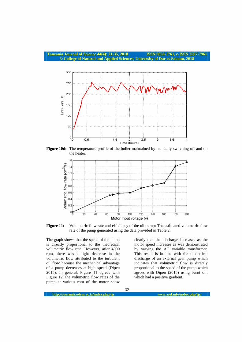
Figure 11 shows the estimated volumetric
flow rate (discharge, Q) of the pump
obtained using the data obtained from Table
2. From the graph, the volumetric flow
increased as the speed of the pump also
increased although at high speeds it was
observed that the flow rate slightly
decreased. This agrees with the theory of
positive displacement external gear pumps
since the gradient of the flow rate is positive
as observed by Wang et al. (2017) during
simulation of flow rate for PD pumps and
the volumetric flow pattern obtained for
burnt oil according to Dipen (2015).
Tanzania Journal of Science 44(4): 21-35, 2018 ISSN 0856-1761, e-ISSN 2507-7961
© College of Natural and Applied Sciences, University of Dar es Salaam, 2018
32 http://journals.udsm.ac.tz/index.php/tjs www.ajol.info/index.php/tjs/
Figure 10d: The temperature profile of the boiler maintained by manually switching off and on
the heater.
Figure 11: Volumetric flow rate and efficiency of the oil pump: The estimated volumetric flow
rate of the pump generated using the data provided in Table 2.
The graph shows that the speed of the pump
is directly proportional to the theoretical
volumetric flow rate. However, after 4000
rpm, there was a light decrease in the
volumetric flow attributed to the turbulent
oil flow because the mechanical advantage
of a pump decreases at high speed (Dipen
2015). In general, Figure 11 agrees with
Figure 12, the volumetric flow rates of the
pump at various rpm of the motor show
clearly that the discharge increases as the
motor speed increases as was demonstrated
by varying the AC variable transformer.
This result is in line with the theoretical
discharge of an external gear pump which
indicates that volumetric flow is directly
proportional to the speed of the pump which
agrees with Dipen (2015) using burnt oil,
which had a positive gradient.

Tanzania Journal of Science 44(4): 21-35, 2018 ISSN 0856-1761, e-ISSN 2507-7961
© College of Natural and Applied Sciences, University of Dar es Salaam, 2018
33 http://journals.udsm.ac.tz/index.php/tjs www.ajol.info/index.php/tjs/
Figure 12: The MIT (2017) interactive gear pump interface was used to generate the graph.
Table 2: The results of the pump's volumetric displacement test
Voltage (V) Current (A) Volume (cm3) Time (s) Q (cm
3/s)
65.5 0.55 185 236.0 0.78
70.0 0.65 185 224.0 0.83
80.2 0.68 185 201.0 0.92
100.4 0.76 185 181.0 1.02
120.2 0.87 185 170.0 1.09
140.1 0.99 185 145.0 1.28
160.7 1.08 185 125.0 1.48
180.2 1.12 185 90.0 2.05
200.0 1.21 185 80.0 2.31
Figure 13 shows the efficiency of pump
generated using the gear pump interactive
interface by MIT (2017). The pump
specification parameters such as the
numbers of teeth, profile involute angle and
pitch diameter were entered in the interface.
The motor speed specification was also
considered. In general, it is observed from
the efficiency graph that the efficiency of the
pump increased rapidly up to nearly about
100 percent speed at around 500 rpm;
however, the efficiency remains nearly
constant for further increase in the speed of
the pump-motor system attributed to
friction, noise, and weight of the moving
parts as reported by Bilyeu (2006) and
Dipen (2015).

Tanzania Journal of Science 44(4): 21-35, 2018 ISSN 0856-1761, e-ISSN 2507-7961
© College of Natural and Applied Sciences, University of Dar es Salaam, 2018
34 http://journals.udsm.ac.tz/index.php/tjs www.ajol.info/index.php/tjs/
Figure 13: The efficiency of the oil pump evaluated with speed of the AC motor.
Conclusions
A pump capable of operating at high
temperatures has been constructed using
locally available materials. The suitability
for high temperature operations of about the
requirement for the TES system (∼200 °C)
was tested. The materials selected for the
construction of the oil pump withstood high
oil temperature up to about 230 °C during
the test period. Furthermore, the pump
constructed was able to circulate oil through
a boiler and charge a hybrid TES tank
consisting oil and pebbles to significant
temperature of 190 °C in 3 hours. The TES
cooking application has been constructed
and demonstrated to show effective cooking
of local foods such as beans and rice as
compared to cooking time for improved
stoves.
Acknowledgements
The authors are grateful to the Makerere
University, Physics Department Kampala-
Uganda and ENPE Project, Makerere
University for all the financial support for
the laboratory work; Material Science and
Solar Energy for Eastern and Southern
Africa (MSSEESA) for research
organization and Dr. Margaret Emmanuel
Samiji of the University of Dar es Salaam
(UDSM), Tanzania and Professor Tom Otiti
of Makerere University (Coordinators of
MSSEESA).
References
Biira S and George K 2014 Analysis of solar
radiation in Uganda: A case study of
Kasese, Jinja and Soroti Districts. Int. J.
Cur. Res. 6(8): 8110-8115.
Birol F 2010 World energy outlook. Int.
Energy Agency 1(3): 6 -9.
Bertsch SS 2016 Multi temperature heat
pumps. Int.J. Refrig. 69: 43-465.
Bilyeu JD 2006 Flow simulation for
optimized performance of displacement
pumps manufactured by engineered
machined products. Master's Thesis,
Michigan Technological University.
http://www.digitalcommons.mtu.edu/etds
/350.
Chow A 2010 A review on photovoltaic and
thermal hybrid solar technology. Appl.
Energ. 87(2): 365-379.
Dipen AR 2015 Performance evaluation of
external gear pump with the used of
burnt oil. Int. J. Adv. Technol. Engin.
Sci. 3: 2348-7550.
Esteban B, Riba JR, Baquero G, Rius A, and
Puig R 2012 Temperature dependence of
density and viscosity of vegetable oils.
Biom. Bioen. 42: 164 -171.
Egbe EAP 2013 Design analysis and testing
of a gear pump. Int. J. Engin. Sci. 3(2):
1-7

Tanz. J. Sci. Vol. 44(4), 2018
35
Gullberg AT, Ohlhorst D and Schreurs, M
2014 Towards a low carbon energy
future: Renewable energy cooperation
between Germany and Norway. Renew.
Energ. 68: 216-222.
Ghionea I, Ghionea A and Constantin, G
2013 Cad-cae methodology applied to
analysis of a gear pump, Proc. Manufact.
Sys. 8(1): 3-8.
Kumaresan G, Vigneswaran VS,
Esakkimuthu, S and Velraj R 2016
Performance assessment of a solar
domestic cooking unit integrated with
thermal energy storage system. J. En.
Stor. 6: 70-79.
Laczik B, Zentay P and Horváth R 2014 A
New approach for designing gear profiles
using closed complex equations. The
method of gear profile generation.
Hungarica 11(6): 1591-72.
Liping C, Yan Z, Fanli Z, Jianjun Z and
Xianzhao T 2011 Modeling and
Simulation of Gear Pumps based on
Modelica/Mworks andreg. In
Proceedings of the 8th International
Modelica Conference, Technical
Univeristy, Dresden, Germany (No. 063,
pp. 421-429). Linköping University
Electronic Press.
Mawire A 2009 Performance of PCM
androckbed storage tank for solar
cookers during charging using
thermosiphoning. Appl. Therm. Engin.
63(1): 746-1021.
Mawire A, Phori A and Taole S 2014
Performance comparison of thermal
energy storage oils for solar cookers
during charging. Appl. Therm. Engin.
73(1): 1323-1331.
MIT 2017 Gear pumps technologies.
Retrieved on 23 June 2017. Available on
http://www.mitstechnologies.com/gear.
Mussard M 2013 A solar concentrator with
heat storage and self-circulating liquid
Science Direct Energy Procedia 50.
Okello D, Nydal OJ, and Banda EJK 2014
Experimental investigation of thermal
de-stratification in rock bed TES systems
for high temperature applications. En.
Convers. Manag. 86: 125-131.
Okello D, Nydal OJ, Nyeinga K, and Banda
EJK 2016 Experimental investigation on
heat extraction from a rock bed heat
storage system for high temperature
applications. J. En. South. Afr. 27(2):
30-37.
Pawar OS, Suryavanshi SC, Khamkar SB,
Shinde PD and Raut PAS 2015 Design
and fabrication of epicyclic internal gear
pump. J. Int. Assoc. Adv. Technol. Sci.
16(3).
Prasanna UR and Umanand L 2011
Modeling and design of a solar thermal
system for hybrid cooking application.
Appl. En. 88(5): 1740-1755.
Perez-padilla R and Schilmann A 2011
Respiratory health effects of indoor air
pollution. Int. J. Tubercul. Lung Dis.
14(9): 1079-86.
Saleem AM 2009 Effect of tooth geometry
on gear pump performance. Tikrit J.
Engin. Sci. 16(4): 20-27.5.
Sedighi M and Zakariapour M 2014 A
review of direct and indirect solar
cookers. Sustain. En. Sci. Edu. Pub. 2(2):
44-51.
United Nations Commission, E. & Africa,
2006 Report on Energy in Africa:
Energy for Sustainable Development.
UBOS (Uganda Bureau of Statistics) 2016
The National Population and Housing
Census 2014–Main Report, Kampala,
Uganda.
Wang C, Shi W, Wang X, Jiang X, Yang Y
Li W and Zhou F 2017 Optimal of
multistage centrifugal pump based on the
combined energy loss model and
computational fluid dynamics. Appl. En.
187: 10-26.
Zhao X and Vacca A 2017 Numerical
analysis of theoretical flow in external
gear Machines. Mechan. Mach. Theory
108: 41-56.