Embed Size (px)
Citation preview

PiXtend Construction manual: PiXtend V1.3 Full
Kit Assembly
Construction manual
PiXtend V1.3 Full Kit Assembly
Qube Solutions UG (limited liability)
Arbachtalstr. 6, 72800 Eningen, GERMANY
http://www.qube-solutions.de/
http://www.pixtend.de
www.pixtend.de Copyright by Qube Solutions UG (limited liability) 1 / 75
Stand 15.08.2016, V1.03

PiXtend Construction manual: PiXtend V1.3 Full
Kit Assembly
This product was developed and produced in accordance with the European directives on the subject and therefore carries the CE sign. The authorized use of the product is described in this data sheet and the belonging assembly- and operating manuals.
Warning:Changes or modifications of the product, as well as the non-compliance of the statements from the mentioned data sheets and operating manuals leads to loss of the approval for the European economic area.
The symbol with the crossed out waste bin means, that the product should be recycled separated to the domestic waste as electronic waste. Where you find the next free acceptance place, will tell you your local administration.
Another possibility is that you send your device back to us and we take care about the correct disposal for you.
www.pixtend.de Copyright by Qube Solutions UG (limited liability) 2 / 75

PiXtend Construction manual: PiXtend V1.3 Full
Kit Assembly
Table of contents1. Introduction & Common.....................................................................................................6
1.1 Scope of delivery.........................................................................................................61.2 Component overview.................................................................................................151.3 Technical aids and tools.............................................................................................171.4 Important information!................................................................................................19
2. Assembling and soldering................................................................................................202.1 IC-Socket...................................................................................................................222.2 Light emitting diodes (LEDs).....................................................................................252.3 Resistors and Potentiometer.....................................................................................302.4 Pin header for Jumper...............................................................................................372.5 Diodes........................................................................................................................402.6 Crystals......................................................................................................................432.7 Capacitors..................................................................................................................442.8 Poly fuse....................................................................................................................482.9 Small Transistors.......................................................................................................492.10 Big Transistors.........................................................................................................512.11 Ferrite / Inductance..................................................................................................532.12 Voltage regulator and cooling element....................................................................552.13 Plug connectors and clamping strips.......................................................................592.14 Relays......................................................................................................................602.15 Assembly of the integrated circuits (ICs).................................................................622.16 Rotation axes...........................................................................................................642.17 Battery......................................................................................................................652.18 Spacers and screw joints.........................................................................................672.19 Jumper.....................................................................................................................68
3. Connecting PiXtend and Raspberry Pi............................................................................71
www.pixtend.de Copyright by Qube Solutions UG (limited liability) 3 / 75

PiXtend Construction manual: PiXtend V1.3 Full
Kit Assembly
Table of FiguresFigure 1: Components of the PiXtend V1.3 Full assembly kit.........................................................................15Figure 2: Technical aids and tools................................................................................................................... 17Figure 3: Usable soldering heads................................................................................................................... 18Figure 4: Mounting direction of the IC-Sockets...............................................................................................22Figure 5: Fixing the IC-Sockets before the soldering......................................................................................23Figure 6: All IC-Sockets fixed.......................................................................................................................... 23Figure 7: IC-Sockets overlie flat...................................................................................................................... 24Figure 8: Alignment of the LEDs..................................................................................................................... 25Figure 9: LED-connection wires bent..............................................................................................................26Figure 10: LEDs crooked soldered................................................................................................................. 26Figure 11: Aligning of the LEDs....................................................................................................................... 27Figure 12: LEDs straight aligned..................................................................................................................... 27Figure 13: Shorten the connection wires.........................................................................................................28Figure 14: Sockets and LEDs mounted..........................................................................................................29Figure 15: "Jacking up" the circuit board.........................................................................................................30Figure 16: Preparing the resistors................................................................................................................... 30Figure 17: Resistors mounted......................................................................................................................... 31Figure 18: 47 kΩ - yellow, violet, black, rot, brown..........................................................................................32Figure 19: 30 kΩ – orange, black, black, rot, brown........................................................................................32Figure 20: 10 kΩ – brown, black, black, rot, brown.........................................................................................32Figure 21: 3,3 kΩ - orange, orange, black, brown, brown...............................................................................32Figure 22: 1,21 kΩ - brown, rot, brown, brown, brown....................................................................................32Figure 23: 680 Ω - blue, grey, black, black, brown..........................................................................................33Figure 24: 470 Ω – yellow, violet, black, black, brown.....................................................................................33Figure 25: 270 Ω - red, violet, black, black, brown..........................................................................................33Figure 26: 120 Ω - brown, red, black, black, brown.........................................................................................33Figure 27: 47 Ω - yellow, violet, black, gold, brown.........................................................................................33Figure 28: 20 Ω 0.1% - red, black, black, gold, violet......................................................................................33Figure 29: Fixing of the resistors..................................................................................................................... 34Figure 30: Placing resistors............................................................................................................................ 35Figure 31: Good soldering joints..................................................................................................................... 35Figure 32: Placement of the Potentiometers...................................................................................................36Figure 33: PiXtend – Resistors and potentiometers mounted.........................................................................36Figure 34: 36-pole pin header and flat pliers...................................................................................................37Figure 35: Needed Jumper blocks.................................................................................................................. 38Figure 36: Bending aid as help for soldering the pin headers.........................................................................38Figure 37: Correct resting pin header.............................................................................................................39Figure 38: Diodes in overview......................................................................................................................... 40Figure 39: Bending of the diodes with bending aid.........................................................................................41Figure 40: Right mounting direction of a diode...............................................................................................41Figure 41: Help at placing the diodes.............................................................................................................42Figure 42: LM4040-diode preparation.............................................................................................................42Figure 43: Clock crystal XTAL3....................................................................................................................... 43Figure 44: 16 MHz XTAL1 for the PiXtend- Controller....................................................................................43Figure 45: Electrolyte capacitors in overview..................................................................................................44Figure 46: Polarity of the electrolyte capacitors..............................................................................................44
www.pixtend.de Copyright by Qube Solutions UG (limited liability) 4 / 75

PiXtend Construction manual: PiXtend V1.3 Full
Kit Assembly
Figure 47: Preparation of the Electrolyte capacitor C9...................................................................................45Figure 48: Electrolyte capacitors C9 mounted................................................................................................45Figure 49: Ceramic capacitors in overview.....................................................................................................46Figure 50: Avoiding of tilting movement..........................................................................................................47Figure 51: Progress of the circuit board..........................................................................................................47Figure 52: Poly fuses in overview................................................................................................................... 48Figure 53: Variants of the TO92-housing........................................................................................................49Figure 54: Orientation of the small transistors................................................................................................50Figure 55: Big Transistors............................................................................................................................... 51Figure 56: Bending the connection wires of the transistors.............................................................................52Figure 57: Positioning of the big transistors....................................................................................................52Figure 58: Montage of the Ferrite................................................................................................................... 53Figure 59: Assembly of the coil....................................................................................................................... 53Figure 60: Coil mounted correct...................................................................................................................... 54Figure 61: Bending the connection wires........................................................................................................55Figure 62: Connection wires bent................................................................................................................... 55Figure 63: Applying the heat-conducting paste...............................................................................................56Figure 64: Voltage regulator with cooling element..........................................................................................57Figure 65: Voltage regulator mounted.............................................................................................................58Figure 66: Montage of the clamping strips......................................................................................................59Figure 67: Position of the Relays.................................................................................................................... 60Figure 68: PiXtend – nearly ready.................................................................................................................. 61Figure 69: Preparation of the ICs.................................................................................................................... 62Figure 70: Correct positioning of an IC with notch..........................................................................................63Figure 71: Correct positioning of an IC with point...........................................................................................63Figure 72: Montage of the rotation axes.........................................................................................................64Figure 73: Check of the soldering joints..........................................................................................................65Figure 74: Battery mounted............................................................................................................................ 66Figure 75: Montage of the spacers................................................................................................................. 67Figure 76: Jumper "SPI_EN".......................................................................................................................... 68Figure 77: PiXtend ready for the marriage......................................................................................................70Figure 78: Plugging the flat ribbon cable to the PiXtend.................................................................................71Figure 79: PiXtend mounted on Raspberry Pi.................................................................................................72Figure 80: Flat ribbon cable connected to the Raspberry Pi...........................................................................73Figure 81: PiXtend with Raspberry Pi Model 2 B – Assembly finished...........................................................74
www.pixtend.de Copyright by Qube Solutions UG (limited liability) 5 / 75

PiXtend Construction manual: PiXtend V1.3 Full
Kit Assembly
1. Introduction & Common
We are happy that you decided for PiXtend!
The available construction instruction guides you, step by step, from the assembly kit to the complete device. We wish you a lot of fun for the assembly and the usage of your own controlling platform.
1.1 Scope of delivery
Once the assembly kit arrives, please check if all components of the following list are included. Please mind that it is only the components for the PiXtend assembly kit and not the optional accessories.
Information to optional accessories (manuals, part lists, …) you can find in our download area on our homepage:http://www.pixtend.de/downloads/
A optical overview over all included components and therefore a help for the a check for completeness gives figure 1.
We recommend to print the overview of all components in tabulator form (incl. Numbering) from side 7 and the placement plan on side 13. All mentioned sides will be needed several times while assembling.
www.pixtend.de Copyright by Qube Solutions UG (limited liability) 6 / 75

PiXtend Construction manual: PiXtend V1.3 Full
Kit Assembly
Labelling (on the board)
Count Description Value
C1, C4, C6, C10, C12, C13, C16, C20, C23, C24, C27, C41
12 Ceramic capacitor, RM 5.08 mm 100 nF
C5, C33, C34, C35, C36, C37, C38, C39, C40, C44, C45, C46, C47, C48, C49
15 Ceramic capacitor, RM 5.08 mm 33 nF
C15, C28, C29, C31, C32, C42, C43
7 Ceramic capacitor, RM 2.54 mm 1 nF
C2, C3, C7, C8, C21, C22 6 Ceramic capacitor, RM 5.08 mm 22 pF
C9 1Electrolyte capacitor radialRM 5.08 mm
1000 μF / 35 V
C14, C17 2Electrolyte capacitor radialRM 5.08 mm
1000 μF / 10 V
C30 1Electrolyte capacitor radialRM 3.5 mm
100 μF / 35 V
C11, C18, C19, C25, C26 5Electrolyte capacitor radialRM 2.54 mm
1 μF / 50 V
D1 1 Precision-Z-Diode LM4040CIZ, TO92 5 V, 0.1%
D2 1Transil diode P6KE36CA, RM 12.7 mm
36 V
D3, D4 2Schottky-Diode SB340 / 1N5822RM 15.24 mm
3 A
D5, D6, D7, D8, D9, D10, D11, D12, D13, D14, D15, D16
12 Diode 1N4004, RM 10.16 mm 1 A
D17, D18, D19, D20, D21, D22
6 Schottky-Diode BAT41, RM 7.62 mm 0,25 A
F1, F2, F3, F4, F5, F6 6 Poly fuse / Multi fuse, RM 5.08 mm 3 A
F7, F8 2 Poly fuse / Multi fuse, RM 5.08 mm 100 mA
F9, F10 2 Poly fuse / Multi fuse, RM 5.08 mm 50 mA
G1 1 Lithium-Battery CR2025, standing 170 mAh, 3 Pin
IC1 1 Atmel ATmega32A-PU, Microcontroller 40 Pin, DIP
IC2 1 LM2576T-5, Switching regulator TO220-5
IC3 1 MAX485-CPA, Transceiver, RS485 8 Pin, DIP
www.pixtend.de Copyright by Qube Solutions UG (limited liability) 7 / 75

PiXtend Construction manual: PiXtend V1.3 Full
Kit Assembly
Labelling (on the board)
Count Description Value
IC4 1 MAX232-CPE, Level Converter RS232 16 Pin, DIP
IC5 1 DS1307(+), RTC 8 Pin, DIP
IC6 1 74HC157, Quad 2 Channel Multiplexer 16 Pin, DIP
IC7 1MicrochipMCP4812-E/P, Dual- DACDigital- Analogue- Converter
8 Pin, DIP
IC8, IC9 2 LM358A, Dual- Operational amplifier 8 Pin, DIP
KK1 1Fischer ElectronicU-Cooling element, SK 13/35
35x17x13 mm
U1 1MicrochipMCP2515-I/P, CAN-Controller
18 Pin, DIP
U2 1MicrochipMCP2551-I/P, CAN-Transceiver
8 Pin, DIP
V1, V2 2 74HCT126N, CMOS Quad Buffer 14 Pin, DIP
JP1 1Female connector, dual-rowed, 2,54 mm
2x4 Pole
JP2 1 Pin header, dual-rowed, 2.54 mm 2x13 Pole
JP10, J11, J12, J13, J14, J15, J16, J17
1Pin header, 2.54 mm Note:
there are 2x36polpin headers
included, whichget cut in two
pieces atassembly!
1x24 Pole
JP18, JP19 1Pin header, 2.54 mm
1x6 Pole
JP4, JP5, JP6, JP7, JP8, JP9
6Pin header, 2.54 mm
1x3 Pole
JP3 1Pin header, 2.54 mm
1x2 Pole
K1, K2, K3, K4 4 Fujitsu FTR-K1CK005W, Relay 1x Changer (SPDT)
L1 1 Ferrite core, inductance, axial 10 μH
L2 1Standing Inductance, Storage chokeWürth 7447480101Fastron 09HCP
100 μH
LED1, LED2, LED3, LED4, LED5, LED6, LED7, LED8, LED9, LED10, LED11, LED12, LED13, LED14, LED15, LED16, LED17, LED18, LED19
19 Standard-LED, 2.54 mm 3 mm, green
www.pixtend.de Copyright by Qube Solutions UG (limited liability) 8 / 75

PiXtend Construction manual: PiXtend V1.3 Full
Kit Assembly
Labelling (on the board)
Count Description Value
Q1, Q2, Q3, Q4, Q5, Q8, Q9, Q12, Q13
9Small Signal- MOSFET- Transistor, TO922N7000(A)
N-Channel0.2 A, 60V
Q6, Q7, Q10, Q11, Q14, Q15 6Power- MOSFET- Transistor, TO220International Rectifier IRFZ44N, 55 V, 41 A
N-Channel
R60, R62 2 Potentiometer, lying, 9 mm 25 kΩ
R4 1 Metal layer-resistor 1/4 W, 0207 47 kΩ, 1 %
R2, R64 R65, R66, R67, R84, R85, R86, R87, R102, R104
11 Metal layer-resistor 1/4 W, 0207 30 kΩ, 1 %
R1, R3, R10, R20, R21, R22, R25, R26, R27, R28, R29, R30, R31, R32, R33, R38, R39, R40, R41, R46, R47, R48, R49, R52, R53, R61, R63, R106, R107, R108, R109, R112, R113, R114, R115
35 Metal layer-resistor 1/4 W, 0207 10 kΩ, 1 %
R103, R105 2 Metal layer-resistor 1/4 W, 0207 3.3 kΩ, 1 %
R15, R16, R17, R18, R19, R23, R24, R72, R73, R74, R75, R76, R77, R78, R79, R92, R93, R94, R95, R96, R97, R98, R99
23 Metal layer-resistor 1/4 W, 0207 1.21 kΩ, 1 %
R6, R7, R11, R12, R13, R14,R100, R101
8 Metal layer-resistor 1/4 W, 0207 680 Ω, 1 %
R8, R34, R35, R36, R37, R42, R43, R44, R45, R50, R51, R68, R69, R70, R71, R88, R89, R90, R91
19 Metal layer-resistor 1/4 W, 0207 470 Ω, 1 %
R54, R55, R80, R81, R82, R83
6 Metal layer-resistor 1/4 W, 0207 270 Ω, 1 %
R5, R9 2 Metal layer-resistor 1/4 W, 0207 120 Ω, 1 %
R56, R57, R58, R59 4 Metal layer-resistor 1/4 W, 0207 47 Ω, 1 %
R110, R111 2 Metal layer-resistor 1/4 W, 0207 20 Ω, 0.1 %
www.pixtend.de Copyright by Qube Solutions UG (limited liability) 9 / 75

PiXtend Construction manual: PiXtend V1.3 Full
Kit Assembly
Labelling (on the board)
Count Description Value
SV1 1 Tub connector, standing 26 Pole
SV2 1 Tub connector, standing 10 Pole
X1 1 Clamping strip RM 5.0 mm, 250-502 2-pole
X2, X7, X8, X10 4 Clamping strip RM 3.5 mm, 250-206 6-pole
X3 1 Clamping strip RM 3.5 mm, 250-203 3-pole
X4 1 Clamping strip RM 5.0 mm, 250-510 10-pole
X5, X6 2 Clamping strip RM 5.0 mm, 250-506 6-pole
X9 1 Clamping strip RM 3.5 mm, 250-208 8-pole
XTAL1 1 Piezoelectric crystal, HC49U-S 16 MHz
XTAL2 1 Piezoelectric crystal, HC49U-S 20 MHz
XTAL3 1Piezoelectric crystal, Clock crystal, TC38
32.768 kHz
1 IC-Socket for IC1 40 Pole
1 IC-Socket for U1 18 Pole
2 IC-Socket for IC4, IC6 16 Pole
2 IC-Socket for V1, V2 14 Pole
6IC-Socket for U2, IC3, IC5, IC7, IC8, IC9
8 Pole
1 PiXtend V1.3 Circuit board 231.5 x 107.5 x 1.6 mm
16 Jumper with handle, 2.54 mm black
1Flat ribbon cable 26 Pole, AWG28 / RM 1.27 mm, 4.5 cm
pre-assembled!1
Post connector 26 Pole for AWG28 / RM 1.27 mm Flat ribbon cable
1Post connector 40 Pole forAWG28 / RM 1.27 mm Flat ribbon cable
2 Quick-release axle for Potentiometer
4 Spacers M2.5 x 25 mm
4Spacers with external thread
M2.5 x 5 mm
www.pixtend.de Copyright by Qube Solutions UG (limited liability) 10 / 75

PiXtend Construction manual: PiXtend V1.3 Full
Kit Assembly
Labelling (on the board)
Count Description Value
8Spacers with external thread
M3x5 mm
8 Spacers M3x15 mm
4 Screw, cross recess M2.5x6 mm
1 Screw, spacers M3x6 mm
1 Heat-conducting paste 1 g
www.pixtend.de Copyright by Qube Solutions UG (limited liability) 11 / 75

PiXtend Construction manual: PiXtend V1.3 Full
Kit Assembly
www.pixtend.de Copyright by Qube Solutions UG (limited liability) 12 / 75

PiXtend Construction manual: PiXtend V1.3 Full
Kit Assembly
www.pixtend.de Copyright by Qube Solutions UG (limited liability) 13 / 75

PiXtend Construction manual: PiXtend V1.3 Full
Kit Assembly
We check every assembly kit before delivery (visual inspection, weight check). If nevertheless a part should be missing so write us an email ([email protected]) and we look immediately that you get a free forwarding.Please do not send back the whole PiXtend kit, if only one part is missing. This will only delay your project and causes expenses and costs for us. Thank you!
www.pixtend.de Copyright by Qube Solutions UG (limited liability) 14 / 75

PiXtend Construction manual: PiXtend V1.3 Full
Kit Assembly
1.2 Component overview
Figure 1 gives an overview over all components included in the assembly kit. Labelling, values and quantities are shown in the previous list.
1. Electrolyte capacitors
2. Poly fuses
3. Ceramic capacitors
4. Resistors
5. Potentiometer & rotation axes
6. Heat- conducting paste
www.pixtend.de Copyright by Qube Solutions UG (limited liability) 15 / 75
Figure 1: Components of the PiXtend V1.3 Full assembly kit
1
2
3
4
5
6
78
9
10 11 12
13
14
15 16
17 1819 20
21 2223

PiXtend Construction manual: PiXtend V1.3 Full
Kit Assembly
7. Lithium- Battery
8. Pin headers and tub connectors
9. PiXtend- board
10.Power transistors
11. Integrated circuits (ICs) and IC-Sockets
12.Diodes and light emitting diodes (LEDs)
13.Cooling elements
14.Pre-assembled flat ribbon cable with 26/40-pole connectors
15.Clamping strips
16.Relays
17.Voltage regulators
18.Ferrite (looks like a oversized resistor) and coil
19.Metal- spacers
20.Screws
21.Jumper
22.Small signal- transistors
23.crystals
Please consider:
The colour and form of small parts can change. We can't guarantee that the components will always look the same as in the overview picture or in the following pictures of the manual.
But the components can be separated by the includes count of pieces or the labelling of the components. If available, the components can be tested and measured with a multimeter.
If you don't have a multimeter and you are not sure with a component so we will help you with pleasure. E-Mail to: [email protected]
www.pixtend.de Copyright by Qube Solutions UG (limited liability) 16 / 75

PiXtend Construction manual: PiXtend V1.3 Full
Kit Assembly
1.3 Technical aids and tools
1. Cutter (small)2. Needle-nosed pliers / Flat nose pliers (small)3. Bending aid (for resistors, capacitors etc.) (optional)4. Cross recess screw driver5. Slotted screwdriver6. Desoldering wick7. Solder (Ø 0,5 mm – 1 mm)
Furthermore it is needed a soldering iron with a head which is thin enough to solder circuit boards. Usable soldering heads are shown in Figure 3.
A common multimeter is not urgently needed, but helpful. Especially at finding failures and differentiate the components (for example resistors).
www.pixtend.de Copyright by Qube Solutions UG (limited liability) 17 / 75
Figure 2: Technical aids and tools
1 2
3 4 5
6 7

PiXtend Construction manual: PiXtend V1.3 Full
Kit Assembly
www.pixtend.de Copyright by Qube Solutions UG (limited liability) 18 / 75
Figure 3: Usable soldering heads

PiXtend Construction manual: PiXtend V1.3 Full
Kit Assembly
1.4 Important information!
Please consider always the assembly- and safety instructions of themanual in further process, which are signed with the yellow warnings sign.
• Always use the the recommended tools and technical aids for the preparation- and assembly steps.
• Before you are forming, soldering, assembling or changing the components in any other way, please be sure that the steps of the construction manual are completely read and understood. If the components once are changed or soldered an exchange or return is impossible.
• Please do all soldering, forming and wiring conscientiously. The result will pay your effort!
• And please read too the safety information in the PiXtend- datasheet and the printed safety instructions, which are included in the assembly kit.
• If the assembly- and operation manuals as well as the technical datasheet are not respected, the approval for the European economic area (CE-conformity) is lost. Please adhere to the instructions and read all provided information before you put the PiXtend in operation.
www.pixtend.de Copyright by Qube Solutions UG (limited liability) 19 / 75

PiXtend Construction manual: PiXtend V1.3 Full
Kit Assembly
2. Assembling and soldering
If you have read the safety- and assembly instructions and checked the completeness of the components with help of the part list and the overview picture, then it can be started with the assembly.
For the soldering and assembly works, depending on the manual dexterity, about 4 hours will be needed. Take enough time to avoid careless mistakes and the consequential rework.
We recommend the following order at placing and soldering.
1. IC-Socket
2. Light emitting diodes (LEDs)
3. Resistors and Potentiometer
4. Pin headers for Jumper
5. Diodes
6. Crystals
7. Capacitors
8. Poly fuses
9. Small Transistors
10.Big Transistors
11. Ferrite and coil
12.Voltage regulators and cooling elements
13.Plug connectors and clamping strips
14.Relays
15.Assembly of the integrated circuits (ICs)
16.Rotation axes
17.Battery
18.Spacers and fittings
19.Setting jumper
www.pixtend.de Copyright by Qube Solutions UG (limited liability) 20 / 75

PiXtend Construction manual: PiXtend V1.3 Full
Kit Assembly
On the following sides the single steps will be shown in this order, illustrated by many pictures and tips.
The order of the placement-, assembly- and soldering steps has no technical relevance. But we assembled some of the PiXtend- boards manually and think that the shown order iswell-suited.
Sure you can use your own order as well.
However we recommend to insert the lithium battery towards the end. So it can be avoidedthat the battery gets a short. A short circuit can damage the battery and the board!
All components are getting placed on the top side of the PiXtend- board and soldered on the bottom side.The top side can be recognized at the white printing.
For fast and failure free work we recommended to print the placement plan and the part listor to open it on the laptop / tablet next to the soldering place. Especially at resistors and capacitors it is helpful to use the digital version of the plans and lists, because in PDFs it ispossible to search for components.
Part list and placement plan you can find in our download area:http://www.pixtend.de/downloads/
www.pixtend.de Copyright by Qube Solutions UG (limited liability) 21 / 75

PiXtend Construction manual: PiXtend V1.3 Full
Kit Assembly
2.1 IC-Socket
The circuit board has to lie on a flat and clean base. The IC-Socket has to be put through the circuit board from the placement side.
All IC-Sockets have a mark (notch) for the mounting direction. This mark is shown too in the white labelling, how you can see in Figure 4.
After putting the socket in the circuit board it is still not fixed and can fall out while turning the board. Hold the socket before turning the board. By bending two opposing pins on the bottom side, the socket can't fall out. (see Figure 5).
Tip for advanced users:
Also you can put in all sockets together and hold them together with a piece of paperboard. If circuit and paperboard is hold together the complete “sandwich” can we turned. The paperboard is lying on the table. Hold the circuit board and pull out the paperboard carefully. This procedure needs sensitiveness, but it make the bending of the pins unnecessary and leads to a faster result.
www.pixtend.de Copyright by Qube Solutions UG (limited liability) 22 / 75
Figure 4: Mounting direction of the IC-Sockets

PiXtend Construction manual: PiXtend V1.3 Full
Kit Assembly
The bending of the opposing pins can be done with the fingernails or with a screwdriver. Figure 6 shows the circuit board with all sockets.
www.pixtend.de Copyright by Qube Solutions UG (limited liability) 23 / 75
Figure 5: Fixing the IC-Sockets before the soldering

PiXtend Construction manual: PiXtend V1.3 Full
Kit Assembly
Start the soldering iron now.Begin with soldering of the already bent pins of every socket. It is not to recommend to solder all pins immediately!
www.pixtend.de Copyright by Qube Solutions UG (limited liability) 24 / 75
Figure 6: All IC-Sockets fixed
Figure 7: IC-Sockets overlie flat

PiXtend Construction manual: PiXtend V1.3 Full
Kit Assembly
If only one of both pins is soldered you still have the possibility to align the socket again. All sockets should be overlie flat on the circuit board how it is shown in figure 7. Should the socket not lie flat on the board, then it is possible that it leads to mechanical problems later at the mounting of the ICs.
Press if necessary with one hand the socket on the circuit board and alternate warming thetwo pins with the soldering iron from the other side (only short time!). Do this with every socket if they are not lying flat.
Attention at the aligning of the sockets!Pay attention that you don't touch the socket at the place which you are warming with the soldering iron from the other side.Danger of burns!
Now all Sockets should lie flat, so all other pins can be soldered. You built a good and solidbase for the integrated circuits that will pay off later.
www.pixtend.de Copyright by Qube Solutions UG (limited liability) 25 / 75

PiXtend Construction manual: PiXtend V1.3 Full
Kit Assembly
2.2 Light emitting diodes (LEDs)
At the LEDs it must be paid attention to the polarity. The longer pin is the anode (+). The anode is marked with a “+” on the circuit board.
The light emitting diodes are put in the board one after another. For the fixing before the soldering it is enough to bend the two connection wires on the bottom side of the circuit board.
www.pixtend.de Copyright by Qube Solutions UG (limited liability) 26 / 75
Figure 8: Alignment of the LEDs

PiXtend Construction manual: PiXtend V1.3 Full
Kit Assembly
We recommend here too to first solder only one pin per LED, so you still have the possibility to correct the position.
The following figure shows the typical position of the LEDs after soldering. Not all LEDs lie good or are crooked. Because of this reason we soldered only one pin.
Use the same method as with the IC-Sockets and press the LED on the board, then heat the bottom side of the soldering joint for short time.
www.pixtend.de Copyright by Qube Solutions UG (limited liability) 27 / 75
Figure 9: LED-connection wires bent
Figure 10: LEDs crooked soldered

PiXtend Construction manual: PiXtend V1.3 Full
Kit Assembly
The heating should be as short as possible, because otherwise the LEDs can be damaged!
After aligning the LEDs all the second pins can be soldered.
If it is not important for you if the LEDs are straight or not, so you sure can solder all pins at once and go on with the next step.
www.pixtend.de Copyright by Qube Solutions UG (limited liability) 28 / 75
Figure 11: Aligning of the LEDs
Figure 12: LEDs straight aligned

PiXtend Construction manual: PiXtend V1.3 Full
Kit Assembly
To complete the assembly of the LEDs it's only to shorten the connection wires with a cutter (Figure 13).
Cut the wires near the soldering joint. Then short circuits between the connection can be avoided best.
www.pixtend.de Copyright by Qube Solutions UG (limited liability) 29 / 75
Figure 13: Shorten the connection wires

PiXtend Construction manual: PiXtend V1.3 Full
Kit Assembly
Your PiXtend-board should look now as following:
www.pixtend.de Copyright by Qube Solutions UG (limited liability) 30 / 75
Figure 14: Sockets and LEDs mounted

PiXtend Construction manual: PiXtend V1.3 Full
Kit Assembly
2.3 Resistors and Potentiometer
For the mounting of the resistors we can use attached spacers to make life easier by “jacking up” the circuit board.
At the four corners of the circuit board the spacers (M3x5 mm with external thread top and M3x15 mm bottom) get screwed as in Figure 15.
Before assembling and soldering of the resistors can be prepared more:
www.pixtend.de Copyright by Qube Solutions UG (limited liability) 31 / 75
Figure 15: "Jacking up" the circuit board
Figure 16: Preparing the resistors

PiXtend Construction manual: PiXtend V1.3 Full
Kit Assembly
How showed in figure 16 the connection wires have to be bent. On which side doesn't matter.
As next step the wires get shortened. The length of the wires should be shorter then 15 mm (measured from the end of the body of the resistor). This is important for the next step:
The resistors can be easily put in the proposed position now.
The single resistors can be differentiated with the colour code. If you don't have a multimeter you can align the colour codes of the resistors with the following pictures.Easiest the colours can be seen at daylight or under a bright light.
You must be sure that you identified the resistors right before you start with the assembling and soldering. If a failure is not found until initial operation it can lead to malfunction or in worst case to defects!
Which resistor values have to be placed on which position you can see on the placement plan and the part list from side 7.
www.pixtend.de Copyright by Qube Solutions UG (limited liability) 32 / 75
Figure 17: Resistors mounted

PiXtend Construction manual: PiXtend V1.3 Full
Kit Assembly
www.pixtend.de Copyright by Qube Solutions UG (limited liability) 33 / 75
Figure 18: 47 kΩ - yellow, violet, black, rot, brown
Figure 20: 10 kΩ – brown, black, black, rot, brown
Figure 19: 30 kΩ – orange, black, black, rot, brown
Figure 21: 3,3 kΩ - orange, orange, black, brown,brown
Figure 22: 1,21 kΩ - brown, rot, brown, brown, brown

PiXtend Construction manual: PiXtend V1.3 Full
Kit Assembly
www.pixtend.de Copyright by Qube Solutions UG (limited liability) 34 / 75
Figure 23: 680 Ω - blue, grey, black, black, brown
Figure 24: 470 Ω – yellow, violet, black, black, brown
Figure 25: 270 Ω - red, violet, black, black, brown
Figure 26: 120 Ω - brown, red, black, black, brown
Figure 27: 47 Ω - yellow, violet, black, gold, brown
Figure 28: 20 Ω 0.1% - red, black, black, gold, violet

PiXtend Construction manual: PiXtend V1.3 Full
Kit Assembly
Some of the resistors already can be differentiated by the different counts. But the colour code or resistor value (with Ω- meter) should be checked still.
It turned out as good to first place all resistors of one type and then solder the first pins.
The resistors can be placed and fixed in the same position (Figure 29).
T some places it is better to place the resistor and fix it directly by a soldering joint. In Figure 30 is shown a place like that. If all four resistors would be placed in the row first, so it would be hard to solder the resistors in the middle.
www.pixtend.de Copyright by Qube Solutions UG (limited liability) 35 / 75
Figure 29: Fixing of the resistors

PiXtend Construction manual: PiXtend V1.3 Full
Kit Assembly
If all resistors are placed and fixed by a soldering joint, then the circuit board can get turned and the second connection wire get soldered.
On the bottom side it should be checked, if on the already fixed connection wires the solder flew down through the hole. If not the soldering point can be heated again and feed with more solder if necessary.
The connection wires of the resistors get cut again with the cutter.
www.pixtend.de Copyright by Qube Solutions UG (limited liability) 36 / 75
Figure 30: Placing resistors
Figure 31: Good soldering joints
(Solder cone on the pad )

PiXtend Construction manual: PiXtend V1.3 Full
Kit Assembly
The two potentiometer are getting put in the board and soldered at one point. So the components can be fixed again if necessary. The other pin of the potentiometers can afterwards be soldered easily on the bottom side.
The spacers are getting removed again and put aside through the final assembly.
www.pixtend.de Copyright by Qube Solutions UG (limited liability) 37 / 75
Figure 32: Placement of the Potentiometers
Figure 33: PiXtend – Resistors and potentiometers mounted

PiXtend Construction manual: PiXtend V1.3 Full
Kit Assembly
2.4 Pin header for Jumper
In the assembly kit are attached two 36-pole pin headers (Figure 34).
The pin headers now can be shortened to the needed length with a flat pliers. As an example we shorten a 3-pole jumper block. The plastic part of the pin header is hold with the pliers on the third pin. With the other hand the rest of the pins (in one piece) can be broken.
Grab with your fingers as near as possible to the predetermined breaking point or the plastic maybe will break at another point as wanted.
Following lengths are needed:
– 1x 24 Pins
– 1x 6 Pins
– 6x 3 Pins
– 1x 2 Pins
The best is to start with the longest piece (24 pins). Should a long piece break at an unwanted place, so it is possible to make another smaller piece out of it.
A certain percentage buffer for failures we indeed have inserted. So some pins will remain.
www.pixtend.de Copyright by Qube Solutions UG (limited liability) 38 / 75
Figure 34: 36-pole pin header and flat pliers

PiXtend Construction manual: PiXtend V1.3 Full
Kit Assembly
The result should look like that:
Like all other parts too, the pin headers are getting put in the board from the top side. Because the headers don't hold from alone it always is getting one piece put in the board, hold and turned.
That the loose put pin header doesn't fall out something has to be laid under. We use the bending aid for that.
www.pixtend.de Copyright by Qube Solutions UG (limited liability) 39 / 75
Figure 35: Needed Jumper blocks
Figure 36: Bending aid as help for soldering the pin headers

PiXtend Construction manual: PiXtend V1.3 Full
Kit Assembly
Here too it is helpful to always solder first the two outside pin to fix it. As next step the position has to be checked. Figure 37 shows a correct positioned (90° to the board) and neatly resting pin header. (24-pole).
After the positioning all other pin can be soldered. This process is getting repeated for all other pin header pieces.
www.pixtend.de Copyright by Qube Solutions UG (limited liability) 40 / 75
Figure 37: Correct resting pin header

PiXtend Construction manual: PiXtend V1.3 Full
Kit Assembly
2.5 Diodes
With the diodes the bending aid will be used for its first “real” purpose. The diodes will be bent to different lengths / grid dimension:
1. SB340 / 1N5822: RM 15.24 mm2. P6KE36CA: RM 12.7 mm3. 1N4004: RM 10.16 mm4. BAT41: RM 7.62 mm5. LM4040CIZ: TO92-housing
The here named dimensions should serve as orientation. If you don't own a bending aid, it is not necessary to exactly bend it to the tenths millimetre.
The bending can be done without bending aid too, by hand (sense of proportion).
The preparation and soldering of the LM4040-diode is explained more detailed in the following.
www.pixtend.de Copyright by Qube Solutions UG (limited liability) 41 / 75
Figure 38: Diodes in overview
34
1
2
5

PiXtend Construction manual: PiXtend V1.3 Full
Kit Assembly
The diodes have a defined mounting direction, which has to be abided. The white ring on the diode is too found on printing on the circuit board. Die BAT41-diodes have a blue basicbody and because of this a black ring as mark.
The P6KE35CA-diode has no defined mounting direction. It doesn't matter in which direction this component will be mounted.
With the diodes it is the same procedure as with the LEDs:Insert, bend connection wires, soldering and if necessary positioning, cutting long connection wires at the bottom side near the soldering joint.
www.pixtend.de Copyright by Qube Solutions UG (limited liability) 42 / 75
Figure 39: Bending of the diodes with bending aid
Figure 40: Right mounting direction of a diode

PiXtend Construction manual: PiXtend V1.3 Full
Kit Assembly
In the area of the digital inputs are standing much resistors in direct environment and make it difficult to put the diodes through the holes. You can pull the wires down from the bottom side or push them from up with a screwdriver.
The LM4040-diode has a special structural shape (TO92-housing). For preparation the pin in the middle has to be bend about 1-2 mm back (in direction of the round housing part), like it is shown in figure 42.
The next step is to mount the LM4040-diode. Then bend the connection wires on the bottom side and solder them.
www.pixtend.de Copyright by Qube Solutions UG (limited liability) 43 / 75
Figure 41: Help at placing the diodes
Figure 42: LM4040-diodepreparation

PiXtend Construction manual: PiXtend V1.3 Full
Kit Assembly
2.6 Crystals
The crystals are getting mounted in the same way how before the LEDs. Only that here you don't have to look for the polarity.
The 20 Mhz- crystal depends to the CAN-Controller, to the microcontroller the crystal with 16 MHz. The round clock crystal is giving the time for the real time clock.
www.pixtend.de Copyright by Qube Solutions UG (limited liability) 44 / 75
Figure 43: Clock crystal XTAL3
Figure 44: 16 MHz XTAL1 for the PiXtend- Controller

PiXtend Construction manual: PiXtend V1.3 Full
Kit Assembly
2.7 Capacitors
Started will be with the electrolyte capacitors;
1. 1x 1000 uF / 35 V
2. 2x 1000 uF / 10 V
3. 1x 100 uF
4. 5x 1 uF
At electrolyte capacitors it must be cared for the polarity. The longer connection wire is the plus pole. The minus pole is marked by a white stripe as shown in Figure 46.
www.pixtend.de Copyright by Qube Solutions UG (limited liability) 45 / 75
Figure 45: Electrolyte capacitors in overview
1 23 4
Figure 46: Polarity of the electrolyte capacitors
PiXtend Construction manual: PiXtend V1.3 Full
Kit Assembly
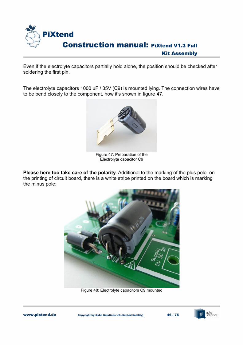
Even if the electrolyte capacitors partially hold alone, the position should be checked after soldering the first pin.
The electrolyte capacitors 1000 uF / 35V (C9) is mounted lying. The connection wires haveto be bend closely to the component, how it's shown in figure 47.
Please here too take care of the polarity. Additional to the marking of the plus pole on the printing of circuit board, there is a white stripe printed on the board which is marking the minus pole:
www.pixtend.de Copyright by Qube Solutions UG (limited liability) 46 / 75
Figure 47: Preparation of theElectrolyte capacitor C9
Figure 48: Electrolyte capacitors C9 mounted

PiXtend Construction manual: PiXtend V1.3 Full
Kit Assembly
Now it is going on with the ceramic capacitors
1. 12x 100 nF
2. 15x 33 nF
3. 7x 1 nF
4. 6x 22 pF
For the ceramic capacitors the direction / polarity doesn't matter. For the rest go on as untilnow.
Caution: Danger of mix-up with the fuses in the following chapter.
The colours and forms of the capacitors can variate.
The ceramic capacitors can be differentiated by the different quantity in the assembly kit or by the printing on each component.
www.pixtend.de Copyright by Qube Solutions UG (limited liability) 47 / 75
Figure 49: Ceramic capacitors in overview
3 41 2

PiXtend Construction manual: PiXtend V1.3 Full
Kit Assembly
If you don't like the tilting while soldering, so it can be helpful to underlay a tool or something else at one side of the board.
The placement of the board is gone far already. If you are not sure that you have done all steps well, so you can compare it with picture 51.
www.pixtend.de Copyright by Qube Solutions UG (limited liability) 48 / 75
Figure 50: Avoiding of tilting movement
Figure 51: Progress of the circuit board

PiXtend Construction manual: PiXtend V1.3 Full
Kit Assembly
2.8 Poly fuse
The fuses are getting mounted same as the ceramic capacitors. Too must be cared for the polarity here.
1. 6x 3 A
2. 2x 100 mA (Caution: Danger of mix-up with ceramic capacitors)
3. 2x 50 mA (Caution: Danger of mix-up with ceramic capacitors)
The form of the components can variate. But they can be differentiated by the size and thequantity easily.
The big 3 A-fuses are one of the highest components on the circuit board. If later the PiXtend-metal housing should be used, then take care that the fuses are not overhanging to high out of the board and press them down all way before soldering. Or they will collide with the housing later. The correct position shows figure 55 in section 2.10.
www.pixtend.de Copyright by Qube Solutions UG (limited liability) 49 / 75
Figure 52: Poly fuses in overview
1
23

PiXtend Construction manual: PiXtend V1.3 Full
Kit Assembly
2.9 Small Transistors
The nine small transistors can be available in two different versions:
At the version on the right side of the picture the pins are bent already an can be mounted directly. The transistor on the left has straight connector pins which have to be bent up withthe pliers a bit
Direct touching of the connection wires with the hands should be avoided. By electrostatic load the transistors can be damaged.
ESD- shoes or ESD- straps are helpful here.
The plastic housing can be touched without problems. If the pins have to be bent, a pliers with plastic handle should be used.
www.pixtend.de Copyright by Qube Solutions UG (limited liability) 50 / 75
Figure 53: Variants of the TO92-housing
PiXtend Construction manual: PiXtend V1.3 Full
Kit Assembly
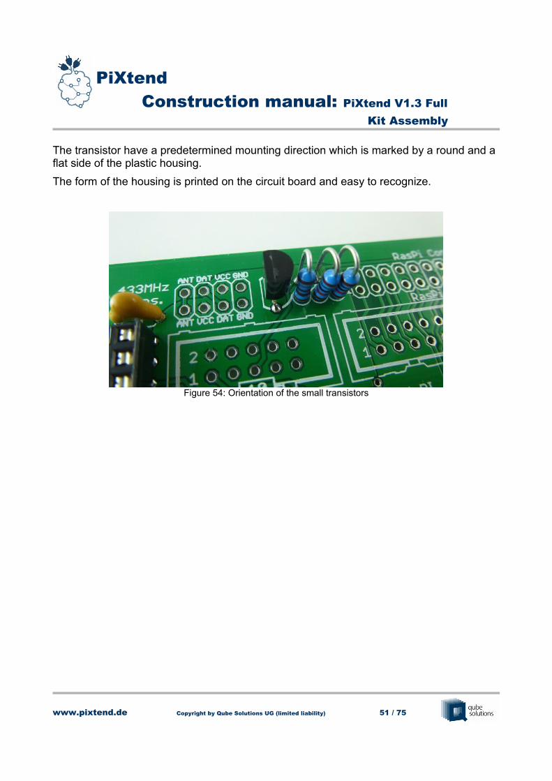
The transistor have a predetermined mounting direction which is marked by a round and a flat side of the plastic housing.
The form of the housing is printed on the circuit board and easy to recognize.
www.pixtend.de Copyright by Qube Solutions UG (limited liability) 51 / 75
Figure 54: Orientation of the small transistors

PiXtend Construction manual: PiXtend V1.3 Full
Kit Assembly
2.10 Big Transistors
The six big transistors are located in close proximity to the 3 A-fuses and form together with them the circuit of the digital outputs.
Same as with the fuses, here is to take care, that the components are getting put to as deep as possible through the board. (as in Figure 57). Are the transistor standing to hight in the board, it can lead to problems with the montage of the metal housing later!
It is to look for the mounting position. On one side the component has a flap with a drill. This side is marked on the circuit board (white stripe - Figure 55).
Direct touching of the connection wires with the hands should be avoided. By electrostatic load the transistors can be damaged.
ESD-shoes or ESD-straps are helpful here.
www.pixtend.de Copyright by Qube Solutions UG (limited liability) 52 / 75
Figure 55: Big Transistors

PiXtend Construction manual: PiXtend V1.3 Full
Kit Assembly
Stick the transistors through the holes and bend the connection wires at the bottom side like it is shown in the following picture.
After soldering one pin of each component it can be adjusted again and if necessary put it deeper through the board. After that the rest of the connection wires are getting soldered and cut with the cutter.
The transistors should be aligned and positioned like that:
www.pixtend.de Copyright by Qube Solutions UG (limited liability) 53 / 75
Figure 56: Bending the connection wires of the transistors
Figure 57: Positioning of the big transistors

PiXtend Construction manual: PiXtend V1.3 Full
Kit Assembly
2.11 Ferrite / Inductance
One connection wire of the Ferrite must be bent and then mounted how it is shown in Figure 58.The first pin can be soldered and fixed from above, same as the resistors.
The coil can have different construction forms, that's why there are different drills for the different grid dimensions. It only must be soldered this pads which through which your component fits best.
www.pixtend.de Copyright by Qube Solutions UG (limited liability) 54 / 75
Figure 58: Montage of the Ferrite
Figure 59: Assembly of the coil

PiXtend Construction manual: PiXtend V1.3 Full
Kit Assembly
Figure 59 shows how to mount the coil. But before the soldering the coil should be presseddown to the board as far as possible (flat lying on the circuit board – Figure 60).
It mustn't be cared of the polarity at ferrite and coils.
www.pixtend.de Copyright by Qube Solutions UG (limited liability) 55 / 75
Figure 60: Coil mounted correct

PiXtend Construction manual: PiXtend V1.3 Full
Kit Assembly
2.12 Voltage regulator and cooling element
The voltage regulator is mounted together with the cooling element. In this process will be applied heat-conducting paste too. The following pictures show the montage.
The connection wires are getting bend at 90° near the housing with the plat pliers.
The completely bent component shows Figure 62.
www.pixtend.de Copyright by Qube Solutions UG (limited liability) 56 / 75
Figure 61: Bending the connection wires
Figure 62: Connection wires bent

PiXtend Construction manual: PiXtend V1.3 Full
Kit Assembly
Now the heat-conducting paste can be applied. Take a little piece of paperboard or a thick paper to apply the heat-conducting paste to the metallic back of the component.
It's only needed a thin layer of paste. “Much helps much” is wrong here. More heat-conducting paste as on the picture should not be applied.
In the assembly kit is included a M3x6 mm screw. With this one the voltage regulator is getting screwed on the cooling element (tighten it hard). The connectors are looking through the opening of the cooling element.
www.pixtend.de Copyright by Qube Solutions UG (limited liability) 57 / 75
Figure 63: Applying the heat-conducting paste

PiXtend Construction manual: PiXtend V1.3 Full
Kit Assembly
The connection wires mustn't touch the cooling element, because it can lead to short circuits!
As last step the pre-mounted voltage regulator with cooling element has to be placed on the circuit board. The cooling element should lie flat on the circuit board.
www.pixtend.de Copyright by Qube Solutions UG (limited liability) 58 / 75
Figure 64: Voltage regulator with cooling element

PiXtend Construction manual: PiXtend V1.3 Full
Kit Assembly
The five connection wires and their pads on the circuit board have only little distance between themselves. After soldering them it has to be checked if on the top side or the bottom side of the board are short circuits between the pads / pins. If necessary remove the unwanted connections with de-soldering wick or with a de-soldering pump.
Check here again if the connection wires have no connection to the cooling element of the voltage regulator.
www.pixtend.de Copyright by Qube Solutions UG (limited liability) 59 / 75
Figure 65: Voltage regulator mounted

PiXtend Construction manual: PiXtend V1.3 Full
Kit Assembly
2.13 Plug connectors and clamping strips
The plug connectors and clamping strips are getting mounted with the same principle as the pin headers.
To avoid that the connectors fall out while turning the board for soldering something can beunderlay again.
The plug connectors and clamping strips should be plugged as deep as possible always and lie neat on the circuit board.
If later wires are getting connected here occurring powers can be absorbed best from the circuit board. If the strips are “hovering” over the board so the soldering points are burdened, which should be avoided!
www.pixtend.de Copyright by Qube Solutions UG (limited liability) 60 / 75
Figure 66: Montage of the clamping strips

PiXtend Construction manual: PiXtend V1.3 Full
Kit Assembly
2.14 Relays
The four relays can be mounted only in one direction because of their connection wires. That the relays don't fall out while turning the circuit board, hold them and use if necessarysomething to underlay.
We recommend to solder only two opposing pins of each relay that it is possible to adjust the position again. Or the relay can be mounted crooked on the board, what optical makes a bad impression.
www.pixtend.de Copyright by Qube Solutions UG (limited liability) 61 / 75
Figure 67: Position of the Relays

PiXtend Construction manual: PiXtend V1.3 Full
Kit Assembly
Now its time to make a compliment!
Now you have your assembly kit on the level of a ARTC-assembly kit (Almost Ready To Control) and with big steps you come near to the completion of the PiXtend-board!
www.pixtend.de Copyright by Qube Solutions UG (limited liability) 62 / 75
Figure 68: PiXtend – nearly ready

PiXtend Construction manual: PiXtend V1.3 Full
Kit Assembly
2.15 Assembly of the integrated circuits (ICs)
Now it is time to put the integrated circuits in the sockets. For an easy an unproblematic connection the pins if the IC should be bent.
The “feet” are standing not exactly straight down, how you can see in Figure 69 (left). The chip can be hold on its plastic housing and then getting pressed against a hard surface until the wanted angel is reached. Like that all Pins of each IC are getting bent equally.
After bending the pins should have an angel of 90° to the plastic housing, how you can seein Figure 69 (right).
When mounting the prepared ICs it is to care for the notch, same as at the montage of the IC sockets.
The notch of the IC, IC socket and the printing on the board have to match.
If the ICs are getting mounted wrong it can lead to malfunction and defects!
www.pixtend.de Copyright by Qube Solutions UG (limited liability) 63 / 75
Figure 69: Preparation of the ICs

PiXtend Construction manual: PiXtend V1.3 Full
Kit Assembly
Some Chips have no notch, they have a point. Picture 71 shows the correct positioning.
www.pixtend.de Copyright by Qube Solutions UG (limited liability) 64 / 75
Figure 70: Correct positioning of an IC with notch
Figure 71: Correct positioning of an IC with point

PiXtend Construction manual: PiXtend V1.3 Full
Kit Assembly
2.16 Rotation axes
The both rotation axes can be easily put in the for it marked positions of the Potentiometer R60 and R62 without any tools.
Even when it functionally makes no different do we recommend to put the “arrows” in the rotation axes in the same orientation. That helps at adjusting the analogue outputs later.
www.pixtend.de Copyright by Qube Solutions UG (limited liability) 65 / 75
Figure 72: Montage of the rotation axes

PiXtend Construction manual: PiXtend V1.3 Full
Kit Assembly
2.17 Battery
It is time for the last use of the soldering iron. The buffer battery for the real time clock (RTC) is getting soldered.
Before that it is advisable to check all soldering work you did until now. Take some minutestime to check to bottom side of the circuit board:
– Are all components soldered neatly? Are there unsoldered pads?→ if necessary resolder
– Are all connection wires shortened?→ if necessary shorten it with the cutter
– Are soldering joints near to each other connected unwanted?→ if necessary cut the unwanted connections (desoldering wick)
www.pixtend.de Copyright by Qube Solutions UG (limited liability) 66 / 75
Figure 73: Check of the soldering joints

PiXtend Construction manual: PiXtend V1.3 Full
Kit Assembly
The top side or placement side of the circuit board should be checked again too:
– Are there connection wires of some components which touch each other (especially resistors)?→ Bend the components a bit to remove the contact
– Are all ICs, electrolyte capacitors, diodes etc. mounted in the right direction?→ if necessary desolder, unmount, turn, and solder again
If you are pleased with the soldering joints and the position of all components, the battery can be soldered. The battery has three connection pins and can be mounted only in one direction. The result shows Figure 74.
www.pixtend.de Copyright by Qube Solutions UG (limited liability) 67 / 75
Figure 74: Battery mounted

PiXtend Construction manual: PiXtend V1.3 Full
Kit Assembly
2.18 Spacers and screw joints
In the assembly kit are different spacers included (M3 and M2,5).
On the outer edge of the circuit board are all together eight drills. Here we need the M3,5 mm spacers with external thread and the M3x15 mm spacers.
Order from left to right (Figure 75):
M3x5 mm – circuit board – M3x15 mm spacers
In the middle of the circuit board are six more drills. Four of them are used for the montageof the Raspberry Pi model B+ / 2 B / 3 B. The rest of the drills are normally not used (they are for the montage of the “old” Raspberry Pi model B (without “+” or “2” / “3”).
Hold the Raspberry Pi over the board before the montage, so it is easier to see which drillsare the right ones.
The order here is the same as with the M3- spacers:
M2,5x5 mm – circuit board – M2,5x25 mm spacers
www.pixtend.de Copyright by Qube Solutions UG (limited liability) 68 / 75
Figure 75: Montage of the spacers

PiXtend Construction manual: PiXtend V1.3 Full
Kit Assembly
2.19 Jumper
As last step before the connection of the Raspberry Pi with the PiXtend the Jumpers are getting set.
To the pin headers / jumpers on the PiXtend we want to give you the most important information:
But in the following the pin headers are placed
– Jumper "SPI_EN":
→ The most important jumper! For standard operation this one has to be placed all time. Without this jumper the Raspberry and the PiXtend can't communicate.
– Jumper next to RS485- or CAN-clamps with the labeling „ON OFF“:
→ The position of this jumper will be important when the interfaces are getting used. More information you can find in the datasheet of PiXtend. For now set the jumper to the position “OFF”.
– Jumper „DO-PWM“ near DO4 and DO5:
www.pixtend.de Copyright by Qube Solutions UG (limited liability) 69 / 75
Figure 76: Jumper "SPI_EN"

PiXtend Construction manual: PiXtend V1.3 Full
Kit Assembly
→ In the first step the jumpers are getting set to the middle and the left pin (position “DO”). Which effect the setting of this jumper has you too will find out in the datasheet.
– Jumper „+5V_PI“ / „ON OFF“ next to the 26poligen tub connector:
→ With this jumper is getting decided if the 5V supply of the PiXtend will be used or not. If you connect only one power supply to the PiXtend and the Raspberry Pi should have no extra supply so this jumper has to be set to “ON”. More infos you find in the datasheet!
– Warning!
– If the jumper “5V_PI” is at position “ON”, then it is not allowed to connect another power supply to the Raspberry Pi.
– The possible compensation currents between the both power supply units can lead to malfunction, overheating of components or even the defect of them!
– Pin header „I²C 5V“ / „SDA SCL“:
→ Is not thought for setting jumpers! Here you can devices be connected to the I²C-bus. Don't set jumpers!
– Jumper „10V 5V“ (analogue inputs) and „5V 24V“ (digital inputs)
→ Should in first step be set to “24V” at the digital inputs and to “10V” at the analogue inputs. Here can be changed the input voltage later if needed.
– If you are not sure at setting the jumpers, so it is always the safest to not set the jumper. More information to the jumpers and there effects you can find in the PiXtend- datasheet.
www.pixtend.de Copyright by Qube Solutions UG (limited liability) 70 / 75

PiXtend Construction manual: PiXtend V1.3 Full
Kit Assembly
PiXtend now is ready for the “marriage” with the Raspberry Pi Model 2 B.
The following steps are valid equally to the model 3B / B+.
www.pixtend.de Copyright by Qube Solutions UG (limited liability) 71 / 75
Figure 77: PiXtend ready for the marriage

PiXtend Construction manual: PiXtend V1.3 Full
Kit Assembly
3. Connecting PiXtend and Raspberry Pi
The connection of the Raspberry Pi and the PiXtend is done quickly.
The 26/40-pole flat ribbon cable with pre-fabricated connectors is getting plugged on the PiXtend first. Because of the “nose” of the connector it is not possible to plug it wrong.
For the beginning the cable is getting bent away from the PiXtend- board (Figure 78) that itdoesn't disturb at the montage of the Raspberry.
As next step the Raspberry Pi can be screwed on the four 25 mm spacers (4x M2,5x6 mm screw). Therefore is needed a little cross recess screw driver.
On the following page you will find a picture with correct aligned Raspberry Pi and a mark of the four screws.
www.pixtend.de Copyright by Qube Solutions UG (limited liability) 72 / 75
Figure 78: Plugging the flat ribbon cable to the PiXtend
PiXtend Construction manual: PiXtend V1.3 Full
Kit Assembly
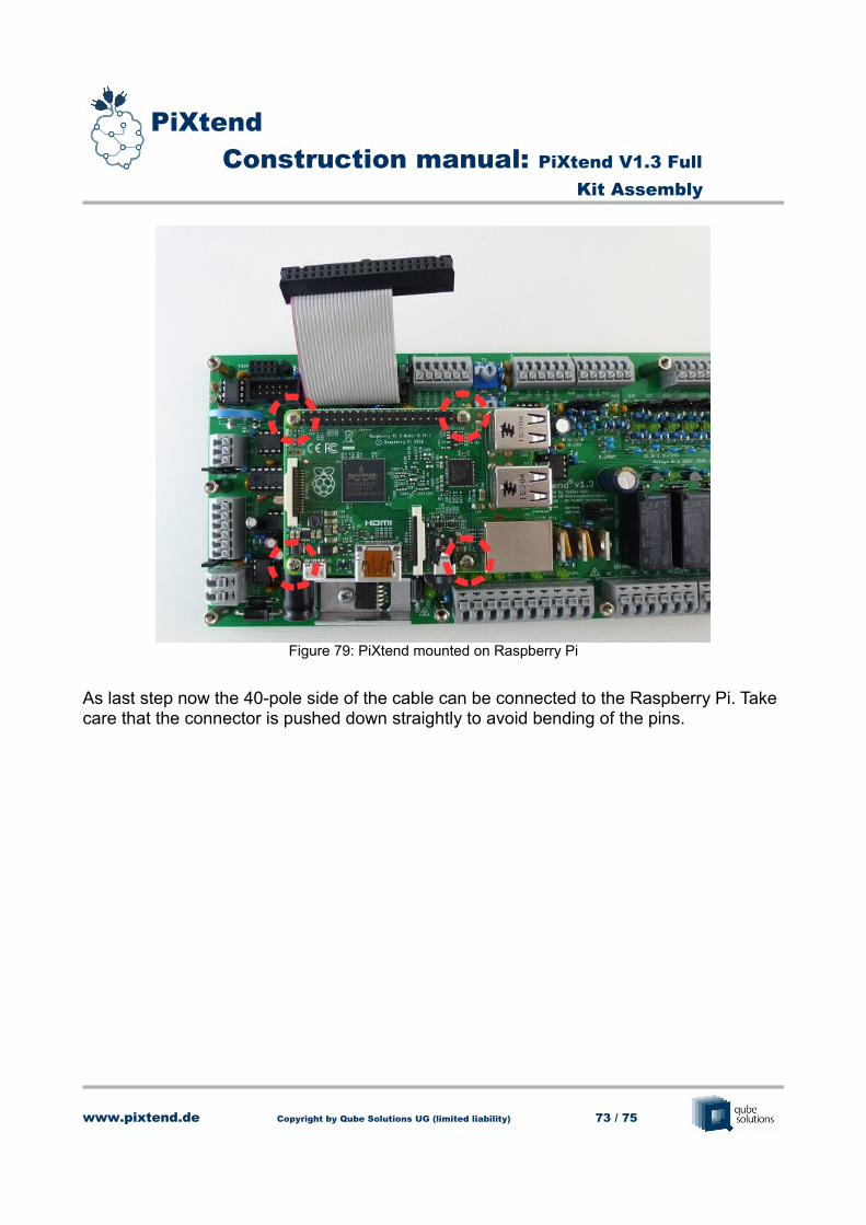
As last step now the 40-pole side of the cable can be connected to the Raspberry Pi. Take care that the connector is pushed down straightly to avoid bending of the pins.
www.pixtend.de Copyright by Qube Solutions UG (limited liability) 73 / 75
Figure 79: PiXtend mounted on Raspberry Pi

PiXtend Construction manual: PiXtend V1.3 Full
Kit Assembly
www.pixtend.de Copyright by Qube Solutions UG (limited liability) 74 / 75
Figure 80: Flat ribbon cable connected to the Raspberry Pi

PiXtend Construction manual: PiXtend V1.3 Full
Kit Assembly
Congratulations!
You have built your own controlling system with the Raspberry Pi Computer now and can start!
All further information to the initial operation, usage and software you can find in the Download-Area of our Homepage.
Please take note of the hints and tips in the initial operation- manual before you connect the PiXtend with a voltage supply the first time.
Do you need help at any point of this manual or do you have questions about the usage or initial operation?
→ Gladly you can contact us over our Forum or per E-Mail.
www.pixtend.de Copyright by Qube Solutions UG (limited liability) 75 / 75
Figure 81: PiXtend with Raspberry Pi Model 2 B – Assembly finished