Embed Size (px)
Citation preview

VILNIUS GEDIMINAS TECHNICAL
FACULTY OF CIVIL ENGINEERING
DEPARTMENT OF CONSTRUCTION TECHNOLOGY AND MANAGEMENT
Ignacio María Veguer Alfonso
CONSTRUCTION DESIGN OF MULTI
MAUDYKLOS STR. IN VILNIUS
VILNIUS GEDIMINAS TECHNICAL UNIVERSITY
FACULTY OF CIVIL ENGINEERING
DEPARTMENT OF CONSTRUCTION TECHNOLOGY AND MANAGEMENT
Ignacio María Veguer Alfonso
CONSTRUCTION DESIGN OF MULTI-DWELLING BUILDING AT
MAUDYKLOS STR. IN VILNIUS
Bachelor thesis
Language: English
Vilnius, 2012
UNIVERSITY
DEPARTMENT OF CONSTRUCTION TECHNOLOGY AND MANAGEMENT
DWELLING BUILDING AT
VILNIUS GEDIMINAS TECHNICAL UNIVERSITY
FACULTY OF CIVIL ENGINEERING
DEPARTMENT OF CONSTRUCTION TECHNOLOGY AND MANAGEMENT
APPROVED Head of Department
________________ (signature)
Edmundas K. Zavadskas
(name, surname)
_______________ (date)
Ignacio María Veguer Alfonso
CONSTRUCTION DESIGN OF MULTI-DWELLING BUILDING AT
MAUDYKLOS STR. IN VILNIUS
Bachelor thesis
Language: English
Supervisor dr. Jonas Saparauskas __ ___________
(name, surname) (signature) (date)
Consultant Remigijus Salna __ ___________
(name, surname) (signature) (date)
Vilnius, 2012

VILNIUS GEDIMINAS TECHNICAL
FACULTY OF CIVIL ENGINEERING
DEPARTMENT OF CONSTRUCTION TECHNOLOGY AND MANAGEMENT
Ignacio María Veguer Alfonso
Construction design of the
VILNIUS GEDIMINAS TECHNICAL
UNIVERSITY
FACULTY OF CIVIL ENGINEERING
DEPARTMENT OF CONSTRUCTION TECHNOLOGY AND MANAGEMENT
Ignacio María Veguer Alfonso
Construction design of the ELNIAKAMPIO NAMAI at Maudyklos gatve 5 in Valakampiai
district in Vilnius (Lithuania)
Final thesis work
Supervisor: Dr. Jonas Saparauskas
Consultant: Dr. Remigijus Salna
Vilnius, 2012
VILNIUS GEDIMINAS TECHNICAL
FACULTY OF CIVIL ENGINEERING
DEPARTMENT OF CONSTRUCTION TECHNOLOGY AND MANAGEMENT
ELNIAKAMPIO NAMAI at Maudyklos gatve 5 in Valakampiai

2
INDEX
1. ARCHITECTURAL PART ........................................................................................................................ 4
1.1 INTRODUCTION ............................................................................................................................. 4
1.2 TERRITORY AND LOCATION........................................................................................................... 4
1.3 CONSTRUCTION AND ARCHITECTURE........................................................................................... 5
1.3.1 DISTRIBUTION ........................................................................................................................ 5
1.3.2 STRUCTURE ............................................................................................................................ 6
1.3.3 FACADES ................................................................................................................................. 8
1.3.4 INTERIOR AND EXTERIOR FINISHES OF BUILDING ................................................................. 9
1.3.5 SERVICES OF BUILDING ........................................................................................................ 11
2. CONSTRUCTIONAL PART ................................................................................................................... 12
2.1 DESIGN OF MONOLITHIC ROOF SLAB ......................................................................................... 12
2.1.1 DESIGN DATA ....................................................................................................................... 12
2.1.2 DESIGN OF MATERIAL CHARACTERISTICS ............................................................................ 12
2.1.3 CALCULATING LOADS ........................................................................................................... 13
2.2 STRUCTURAL ANALYSIS OF SLAB ................................................................................................. 16
2.2.1 ANALYSIS .............................................................................................................................. 16
2.2.2 RESULTS ................................................................................................................................ 16
2.2.3 DESIGN OF SLAB REINFORCEMENT ...................................................................................... 17
3. TECHNOLOGICAL CARDS ................................................................................................................... 22
3.1 TECHNOLOGICAL CARD OF GYPSUM PLASTERBOARD PARTITIONS ........................................... 22
3.1.1 GENERAL DESCRIPTION ........................................................................................................ 22
3.1.2 CONSTRUCTION PROCESS .................................................................................................... 23
3.1.3 INSTALLATION SEQUENCE.................................................................................................... 25
3.1.4 ORGANIZATION OF WORKS ................................................................................................. 26
3.1.5 HUMAN SAFETY ................................................................................................................... 27
3.1.6 MECHANICS, MATERIALS AND TOOLS ................................................................................ 27
3.1.7 QUALITY CONTROL ............................................................................................................... 27
3.1.8 TECHNICAL ECONOMICS INDICATORS ................................................................................ 28
3.1.9 SOME DETAILS ...................................................................................................................... 28
3.1.10 BUDGET ............................................................................................................................. 31
3.2 TECHNOLOGICAL CARD OF VENTILATED FAÇADE (CERAMIC) .................................................... 33
3.2.1 GENERAL DESCRIPTION ........................................................................................................ 33

3
3.2.2 CONSTRUCTION PROCESS .................................................................................................... 34
3.2.3 CONSTRUCTION SEQUENCE ................................................................................................. 36
3.2.4 ORGANIZATION OF WORKS ................................................................................................. 37
3.2.5 HUMAN SAFETY ................................................................................................................... 38
3.2.6 MACHINES, MATERIALS AND TOOLS.................................................................................... 38
3.2.7 QUALITY CONTROL ............................................................................................................... 38
3.2.8 SOME DETAILS ...................................................................................................................... 39
3.2.9 BUDGET ................................................................................................................................ 42
3.2.10 TECHNICAL ECONOMICS INDICATORS ............................................................................... 42
4. ORGANIZATION PART ........................................................................................................................ 43
4.1 MASTERPLAN .............................................................................................................................. 43
4.1.1 DESCRIPTION ........................................................................................................................ 43
4.1.2 SELECTION OF TOWER CRANE ............................................................................................. 43
4.1.3 SETTING OF DANGEROUS ZONE ........................................................................................... 46
4.1.4 TEMPORARY ROAD .............................................................................................................. 52
4.1.5 TEMPORARY STORAGE BUILGINGS AND SITES ................................................................... 52
4.1.6 TEMPORARY BUILGINGS ...................................................................................................... 53
4.1.7 TEMPORARY BUILGINGS ...................................................................................................... 53
4.1.8 CONSTRUCTION SITE LIGHTING ........................................................................................... 55
4.1.9 TEMPORARY WATER SUPPLY ............................................................................................... 55
4.1.10 TEMPORARY SEWERAGE .................................................................................................... 56
4.1.11 FENCE OF CONSTRUCTION SITE ......................................................................................... 56
4.1.12 GENERAL REQUERIMENTS OF LABOR SAFETY ................................................................... 56
4.1.14 REQUIREMENTS OF ENVIRONMENTAL PROTECTION ........................................................ 58
4.1.15 REQUIREMENTS OF FIRE PROTECTION .............................................................................. 58
4.2 ORGANIZATION ........................................................................................................................... 59
4.2.1 TABLES OF MACHINERY AND WORKFORCE ......................................................................... 59
BILIOGRAPHY ........................................................................................................................................ 61
Websites: .............................................................................................................................................. 61

4
1. ARCHITECTURAL PART
1.1 INTRODUCTION
Elniakampis apartment house is located in the forest on a quiet Elniakampis Street in a
prestigious district of Vilnius – Valakampiai. A small three-storey 17-apartment house is
designed to let in the maximum amount of natural light.
The layout of the apartments is both convenient (from 34,90 m² to 140,20 m²) and practical.
Each apartment comes with a box room, parking place under the house and economical gas
heating. There is a possibility to install fireplaces in each apartment.
A bus stop (No. 15) is just 200 m away from the house. Just a couple of kilometres away you
would find Nemencine Road, leading you to the shopping center, Sauletekis University
campus and Baltic-American Clinic that provides medical services 24 hours a day. All the
infrastructure of Antakalnis district is nearby.
Surfaces: - Building area: 671.47 m²
- Plot: 1200 m²
1.2 TERRITORY AND LOCATION
The land plot is in Vilnius city Antakalnis elderate, at the beginning of Elniakampis Street
(coming from Svajonių Street). Elniakampis Street is on the one side of the land plot and an
undeveloped forest territory – on the other. The land plot does not border any other plots,
except for the state land. The area of the land plot – 1200 m². The undeveloped part of the
plot will be laid with blocks, pavement tiles and lawns.
Access to the territory is from Elniakampis Street.
Figure 1. Location

5
1.3 CONSTRUCTION AND ARCHITECTURE
1.3.1 DISTRIBUTION
The house will have 17 apartments spread over three floors. Each floor is made with a
different distribution, the first floor has two apartments of 54.1 m², one of 53.4 m², two of
63.7 m², one of 55.1 m, and one of 34.9 m². The second floor contains one of 90 m², one of
54.1 m², one of 52.3 m², one of 55 m², and two of 63.6 m². The third floor contains one of
49.6 m², one of 68 m², one of 53.5 m², and the most important flat with 140.2 m². The
different distributions are in figure 2.
The ground floor has a car park for 19 cars surrounded by a hedge. The entrances to parking
spaces are open, without gates.
The apartments are accessible through the staircase and an elevator. The elevator of 1125
kg carying capacity has been designed and it has four stops. Lift doors, some apartment and
all common area doors are 1 m wide, i.e. accessible for the disabled. Access from the lift to
the parking lot has a 5 cm sloping ramp.
Figure 2.
Distribution

6
1.3.2 STRUCTURE
FUNDATION
After the geotechnical study and testing of the ground it was decided that the foundation of
the building was to be on piles of reinforced concrete with pile cap. Figure 3
The reinforcement are shaped as if they were cages, the longitudinal reinforcement bars are
made up of evenly placed around the perimeter of the section, and the armed cross is
formed by a spiral hoop or hoops of 6 mm round. section, with a spacing of 20 cm. The
outer diameter of the belt is equal to the diameter of the pile, minus 8 cm, thus obtaining a
minimum thickness of 4 cm. The number of bars and the diameter thereof is calculated
according to the load that has to bear the pile.
The concrete used for the execution of piles concreted "in situ" shall meet the requirements
of the Spanish current Structural Concrete (EHE-2008), the effect of Instruction for Receiving
Cement, and a number of specific requirements for the case of piles concreted "in situ",
which are: The maximum aggregate size not exceeding 32 mm, or quarter round the
longitudinal separation, by selecting the smaller of the two dimensions. The cement content
is higher than 350 kg/m3, is recommended to be 400 kg / m3. The content of fine particles
in the concrete, including cement and other fine materials, shall be between 400 kg/m3 and
550 kg/m3. The water / cement ratio and the use of additives will be determined by the
current Structural Concrete (EHE-2008), must be approved by the Director of Work. The
minimum resistance of the concrete shall be in the Project or otherwise directed by the
Director of Works, not being less than that specified by the EHE. Furthermore it should not
be attacked by water.
The piles were decapitated, thereby eliminating the concrete always of low quality remains
at the top. So reinforcements are exposed to intertwine the pile cap. The length of the
reinforcement must allow post-heading, are protruding from the pile about 50 cm.
Longitudinal reinforcements of the pile are spliced by a minimum overlap of 40 cm., Are
welded or wired throughout its length. If you use proper fencing as a transverse
reinforcement, the closures are made for overlap of 8 cm or more and are welded or wired.
The overlap is alternated for successive fences. Trusses are attached firmly to form a cage
that supports concreted. Each pile is concreted at once without interrupting the operation,
not supported concrete joints. At the end of the pile should be concreted to a height greater
than the final, which exceeds concrete is demolished when it has set. Do not effect the
displacement of piles driven in or yokes in an area less than 3 m. around the pile until the
concrete has a minimum strength of 30 kg/cm2, according to previous tests. Decapitated
after the ground piles protrude sufficiently to allow embedment in concrete of at least 5 cm
to the pile cap.

7
Figure 3. Detail of fundation
COLUMNS
Monolithic columns of rectangular and square cross-section (figure 4) made of reinforced
concrete.
The concrete we are going to use will be C25/30 (project) and C20/25 in the roof floor and
C30/37 in foundation columns.
The iron for our columns will be S275J.
The column measures are: 38 x 38 cm.
Figure 4. Detail of colum

8
SLABS
Our slabs are built with reinforced concrete with a reinforced top and a reinforced bottom.
Also will contain reinforcements in areas of bending moments. All slabs will be of 22 cm of
thickness. Figure 5.
The concrete will be C20/25 in all floors (project).
The iron will be S275J.
Figure 5. Detail of slab
1.3.3 FACADES
There are two kinds of façade. Ventilated façade of ceramic finishing, and inclined ventilated
façade with slate finishing. Both are built of blocks, with exterior thermal insulation
composed of non-combustible mineral wool. Ventilated façade with ceramic finishes will be
explained in one of technological cards. Figure 6.
Staircase windows made of aluminum frames. On all floors, dark grey.
Apartment window frames made of wood, twin-chamber glazing with selective internal
glass. Window frames are dark grey on the outside. Clear glass. To ensure natural
ventilation, all window frames have air vents.

9
Figure 6. Detail of facade
1.3.4 INTERIOR AND EXTERIOR FINISHES OF BUILDING
Doors of the apartments are high-security type, with two locks; imitation wood finish, with a
peephole.
The floor finishes are parquet inside of apartments except kitchens and bathrooms. In that
rooms will be ceramic gres tiles in different colors. And in the terraces and balconies will be
stone tiles.
Parking lot laid with concrete blocks, ceiling covered with decorative plaster, glass doors;
marking done with reflective paint.
Maintenance areas, staircases and corridors laid with stone tiles, walls and ceiling daubed
and painted. A boxroom designed for every apartment.
Interior walls of blocks will be plastered and painted. There are some plasterboard
partitions that will be painted too. One of the technological cards is about plaster boards
partitions. In this technological card, will be explained everything.
The roof is laid with bituminous adhesive covering with powder, brown. Chimneys are tin.

10
Figure 7. Legend of rooms of 2 floor

11
1.3.5 SERVICES OF BUILDING
Apartment ventilation. Natural. Air is being extracted from kitchens and lavatories
and ejected above the roof. The air inflows through the air vents in window frames.
Electricity. The electricity distribution room of the building is equipped with decollator from
which a switchboard is connected. Each flat is installed with a power distribution panel with
voltage tripping devices. Two-tariff meters.
Water Supply. Cold water supplied from the city water supply network. Hot water prepared
centrally in the gas boiler-room. Hot and cold water pipelines are laid to the mains water
lines planned for the project. Each apartment is equipped with hot and cold water meters.
Sewerage. Sewer pipes laid to mains sewerage planned in the project.
Fireplaces. The possibility to install a fireplace is planned for every apartment. Chimney
flues with clean-out openings are installed. There is a possibility to install an additional
fireplace in the mansard or on the terrace.
Fire alarm with smoke detectors and manual fire hazard alarms.
Gas heating, common boiler-room for the building. Two 100kW condensing boilers planned.
Individual meters with integrated temperature sensor for each apartment. Heating
appliances – pressed steel radiators, convectors.
Cables are laid for installation of telephones, television and the Internet.

12
2. CONSTRUCTIONAL PART
2.1 DESIGN OF MONOLITHIC ROOF SLAB
In this part there is the calculation of one representative part of the roof slab of the
building.
2.1.1 DESIGN DATA
The basic for design slab is presented data in table 2.1.1.
DATUM VALUE
Characteristic cylinder strength of concrete fck (MPa) 20
Characteristic strength of s400 steel fyk (MPa) 400
Characteristic density of reinforced concrete (kN/m³) 25
Partial safety factors:
γg – permanent load safety factor
γq – variable load safety factor
1.35
1.3
Exposure class (environmental conditions) XC1
Minimum cover of longitudinal conditions cmin (mm) 35
Table 2.1.1.
2.1.2 DESIGN OF MATERIAL CHARACTERISTICS
1. CONCRETE C20/25
Design concrete compressive strength:
��� = � · ��� · ����� = 0.9 · 1 · 20
1.5 = 12 MPa.
2. STEEL CLASS S400
Design tensile strength fyd = 400/1.15 = 348 MPa when the steel is used as longitudinal
reinforcement.
13
2.1.3 CALCULATING LOADS
2.1.3.1 SNOW LOAD
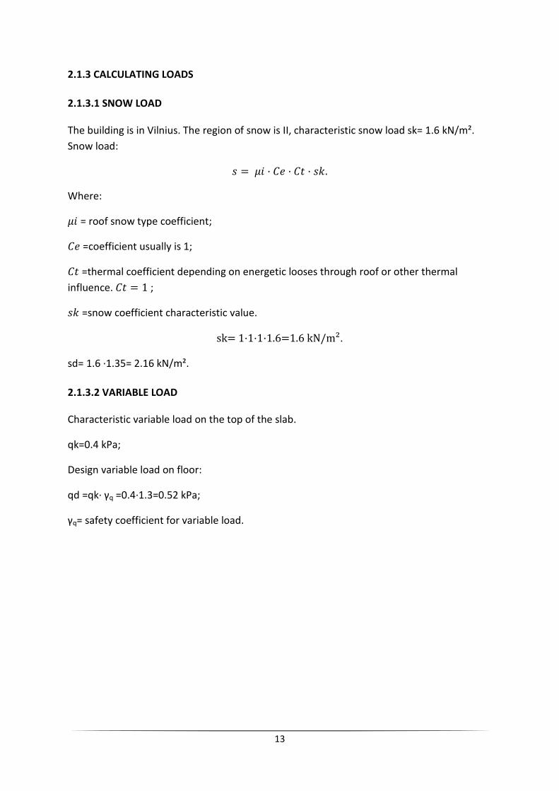
The building is in Vilnius. The region of snow is II, characteristic snow load sk= 1.6 kN/m².
Snow load:
� = �� · �� · �� · ��. Where:
�� = roof snow type coefficient;
�� =coefficient usually is 1;
�� =thermal coefficient depending on energetic looses through roof or other thermal
influence. �� = 1 ;
�� =snow coefficient characteristic value.
sk= 1·1·1·1.6=1.6 kN/m².
sd= 1.6 ·1.35= 2.16 kN/m².
2.1.3.2 VARIABLE LOAD
Characteristic variable load on the top of the slab.
qk=0.4 kPa;
Design variable load on floor:
qd =qk· γq =0.4·1.3=0.52 kPa;
γq= safety coefficient for variable load.

14
2.1.3.3 PERMANENT LOADS
Characteristic value of permanent distributed load from the slab is determined by the floor
cover and the weight of the slab specified in the following table:
Type of structural
layer Layer thickness (m)
Characteristic value
of density yk
(kN/m³)
Characteristic
permanent (self-
weight) load (kPa)
Hydroinsulation 0.02 2500 0.490
Thermal insulation 0.03 80 0.023
Thermal insulation 0.22 60 0.129
Vapor barrier 0.005 9.22·10¯⁴ 4.5·10¯⁸
Concrete C12/16 0.04 2500 0.981
Formation of coat 0.04 350 0.137
Concrete slab 0.22 2500 5.395
Table of materials.
Figure 8. Slab covering of roof.

15
Characteristic value of floor covering and slab covering:
g1k=t1·y1·g;
t1=thickness of layer (m);
y1=density of the layer kg/m;
g=acceleration of free m/s;
γg1=partial safety coefficient for self weight = 1.35;
g1k =t1·y1·g=0.02·2500·9.81= 490.5 = 0.490 kPa;
g2k =t2·y2·g=0.03·80·9.81= 23.54 = 0.023 kPa;
g3k =t3·y3·g=0.22·60·9.81= 129.5 = 0.129 kPa;
g4k =t4·y4·g=0.005·9.22·10¯⁴·9.81= 4.5·10¯⁵ = 4.5·10¯⁸ kPa;
g5k =t5·y5·g=0.04·2500·9.81= 981 = 0.981 kPa;
g6k =t6·y6·g=0.04·350·9.81= 137.34 = 0.137 kPa;
g7k =t7·y7·g=0.22·2500·9.81= 5395.5 = 5.395 kPa.
Design value of loading
g1d =g1k· γg1=0.490 ·1.35= 0.662 kPa;
g2d =g2k· γg1=0.023 ·1.35= 0.031 kPa;
g3d =g3k· γg1=0.129 ·1.35= 0.174 kPa;
g4d =g4k· γg1=4.5·10¯⁸ ·1.35= 6.07·10¯⁸ kPa;
g5d =g5k· γg1=0.981·1.35= 1.324 kPa;
g6d =g6k· γg1=0.137·1.35= 0.185 kPa;
g7d =g7k· γg1=5.395·1.35= 7.283 kPa.
Design loads
gk =0.490 +0.23 +0.129 +4.5·10¯⁸ +0.981+0.137 +5.395 = 7.157 kPa;
gd =0.662 +0.31 +0.174 +6.07·10¯⁸ +1.324 +0.185 +7.283 = 9.662 kPa.
Total load (permanent + variable)
gk = 7.157 + 0.4 = 7.557 kPa;
gd = 9.662 + 0.52 = 10.182 kPa.
Total load (permanent + snow)
gk = 7.157 + 1.6 = 8.757 kPa;
gd = 9.662 + 2.16 = 11.822 kPa.

16
2.1.3.4 TYPES OF LOADING
Internal forces are calculated depending on types of loading. These types of loadings will be
made:
1. g + q1 = self-weight and variable load;
2. g + s = self-weight and snow load.
Maximum moments are taken to have an envelope of the structure.
2.2 STRUCTURAL ANALYSIS OF SLAB
2.2.1 ANALYSIS
The slab was analyzed by hand calculating by frames to take the moments. Firstly is
calculated the frame in axis C and, and then, the frame in axis 3 (fig. 9). With this frames we
can calculate the reinforcement of that part of the slab. I used as a design load self weight
plus snow load because is more restrictive.
2.2.2 RESULTS
Beams that we will study in both directions are presented in fig. 9:
Figure 9. Slab with axes.

17
Figure 10. Frame on axis C.
gd + sd = self-weight and snow load -> qd = 9.662 + 2.16 = 11.822 kPa;
M1 = (qd · b · l²)/16;
M2 = (qd · b · l²)/11;
Where:
M= moment;
qd= design load;
b= width of frame;
l= distance between supports;
M1 = (11.82 · 5.7 · 5.4²)/16 = 122.7 kNm;
M2 = (11.82 · 5.7 · 5.4²)/11 = 178 kNm.
Figure 11. Frame on axis 3.
M1 = (11.82 · 5.46 · 4.94²)/16 = 98.4 kNm;
M2 = (11.82 · 5.46 · 6.5²)/11 = 247.9 kNm.
2.2.3 DESIGN OF SLAB REINFORCEMENT
The required reinforcement will be provided in a way of saving labour and steel. Steel bars
will be tied at the points of intersection using special wire for tieding. Tied of steel bars must
resist positive and negative bending moments.
Preliminary assumption – to use 12 mm diameter bars for constructing the main
reinforcement.

18
Effects for designing slab are chosen depending on direction and top or bottom
reinforcement. Reinforcement will be calculated in two directions. The calculation scheme is
presented in fig 12,13.
Figure 12. Cross section of slab.
Where:
As = steel area;
a1 = minimum cover = 25 mm;
h = height of slab = 220 mm;
d1 = h – a1 = 220 – 25 = 185 mm.
Figure 13. Calculation scheme of RC slab.
ΣH= 0; fyd · As = fed · 1 · Xeft;
Xeft= fyd·Asfed ;
ΣM= 0; MEd ≤ MRd = fcd · 1 Xeft · (d1 – (Xeft/2)).

19
Resisting moments MRd of one meter width slab is presented in table 2.2.3.
Data:
Concrete C 20/25;
fck= 20 MPa;
fcd = (20/1.5) · 0,9 = 12 MPa;
Steel S400;
fsk = 400 MPa;
fsd = 400/1.15 = 348 MPa.
RESISTING MOMENTS OF 1 M SLAB (Step of bars in 200 mm)
1 bar 5 bars MRd (kNm)
Ø 10 mm 0.78 · 10¯⁴ 3.92 · 10¯⁴ 24.32
Ø 12 mm 1.13 · 10¯⁴ 5.65 · 10¯⁴ 33.98
Ø 14 mm 1.54 · 10¯⁴ 7.69 · 10¯⁴ 46.52
Ø 16 mm 2.01 · 10¯⁴ 10.05 · 10¯⁴ 59.52
Ø 18 mm 2.54 · 10¯⁴ 12.72 · 10¯⁴ 73.74
Table 2.2.3. Resisting moments of 1 m slab.
Calculation of resisting moment
Ø 10 mm
Xeft= 348 · 3.92 · 10ˉ,
12 = 0.0113 mm;
Mpd = 12 · 10³ · 0.0113 · (0.185 – (0.0113/2)) = 24.32 kNm.
Ø 12 mm
Xeft= 348 · 5.65 · 10ˉ,
12 = 0.016 mm;
Mpd = 12 · 10³ · 0.016 · (0.185 – (0.016/2)) = 33.98 kNm.

20
Ø 14 mm
Xeft= 348 · 7.69 · 10ˉ,
12 = 0.0223 mm;
Mpd = 12 · 10³ · 0.0223 · (0.185 – (0.0223/2)) = 46.52 kNm.
Ø 16 mm
Xeft= 348 · 10.05 · 10ˉ,
12 = 0.0291 mm;
Mpd = 12 · 10³ · 0.0291 · (0.185 – (0.0291/2)) = 59.52 kNm.
Ø 18 mm
Xeft= 348 · 12.72 · 10ˉ,
12 = 0.0368 mm;
Mpd = 12 · 10³ · 0.0368 · (0.185 – (0.0368/2)) = 73.74 kNm.
Calculation of top reinforcement in axis C direction
Distribution of moments in the frame is presented in fig. 13.1.
MEd = 178 kNm => Acting moment in central part of frame.
(178 · 0.75)/(5.7/2)= 46.84 kNm/m ;
If main top net is 12/12/200/200 and has a resistance of 33.98 kNm,
46.84 – 33.98 = 12.86 kNm that we have to reinforce. We will take Ø 12 mm bars to
reinforce the top in C axis direction. Ø 10 mm would be enough but we will take Ø 12 mm to
make the built simpler, and we have less possibilities to make less errors.
M = 178 kNm => Acting moment in central part of frame.
(178 · 0.5)/(5.7/2)= 31.11 kNm/m ;
If main top net is 12/12/200/200 and has a resistance of 33.98 kNm,
31.11< 33.98 so it is not necessary to reinforce. The same will be in bottom reinforcement.

21
l/4 50% M l/2 75% M l/4 50% M
Figure 13.1. Distribution of moments in the frame.
Top reinforcement in axis 3 direction
M = 247.88 kNm=> Acting moment in central part of frame.
(247.88 · 0.75)/(5.4/2)= 68.85 kNm/m ;
If main top net is 12/12/200/200 and has a resistance of 33.98 kNm,
68.85 – 33.98 = 34.87 kNm that we have to reinforce. We will take Ø 14 mm bars to
reinforce the top in C axis direction.
(247.88 · 0.5)/(5.4/2)= 45.4 kNm/m;
If main top net is 12/12/200/200 and has a resistance of 33.98 kNm,
45.4 – 33.98 = 11.42 kNm that we have to reinforce. We will take Ø 10 mm bars to reinforce
the top in C axis direction.
Bottom reinforcement in axis C direction
M = 178 kNm=> Acting moment in central part of frame.
(178 · 0.75)/(5.7/2)= 46.84 kNm/m;
If main top net is 12/12/200/200 and has a resistance of 33.98 kNm,
46.84 – 33.98 = 12.86 kNm that we have to reinforce. We will take Ø 12 mm bars to
reinforce the top in C axis direction. Ø 10 mm would be enough but we will take Ø 12 mm to
make the built simpler, and we have less possibilities to make less errors.
Top reinforcement in axis 3 direction
M = 247.88 kNm=> Acting moment in central part of frame.
(247.88 · 0.75)/(5.4/2)= 68.85 kNm/m;
If main top net is 12/12/200/200 and has a resistance of 33.98 kNm,
68.85 – 33.98 = 34.87 kNm that we have to reinforce. We will take Ø 14 mm bars to
reinforce the top in C axis direction.
(247.88 · 0.5)/(5.4/2)= 45.4 kNm/m;
If main top net is 12/12/200/200 and has a resistance of 33.98 kNm,
45.4 – 33.98 = 11.42 kNm that we have to reinforce. We will take Ø 10 mm bars to reinforce
the top in C axis direction.
Disposition of this bars is presented in drawing CONSTRUCTIONAL PART, number 2.

22
3. TECHNOLOGICAL CARDS
3.1 TECHNOLOGICAL CARD OF GYPSUM PLASTERBOARD PARTITIONS
3.1.1 GENERAL DESCRIPTION
We are going to study the plasterboards of second floor. There are 70.7 m² of normal
plasterboard and 25.93 m² of waterproof plasterboard. Waterproof plasterboard will be in
wet zones such as bathrooms.
Plasterboard partitions are composed of a metal frame and gypsum board screwed to each
side. The metal frame is attached to the original construction and constitutes a support for
mounting plates.
For special cases you can use a double structure with adequate separation. In the gap
between the plates can be placed a fiberglass or rock lada for greater thermal and acoustic
insulation and for fire protection. Furthermore, in the gap can perform the necessary
facilities (electric, sanitary etc.).
Structure
- Rail 48 mm. Firmly attached to the floor and roof.
- Upright vertical 48 mm. Introduced into the lower and upper channel separation of 400 or
600 mm. As needed.
- Start and end uprights fixed to the structure of encounter.
- Other free intermediate uprights, without setting the upper and lower canals.
- In double grid walls when these are separated more than 5 mm., fix with gusset plates 300
mm.
- To stitch height uprights, you can use one of the following three methods:
a) A piece of a canal to the studs.
b) A piece of upright in a drawer two arriving
c) Insert a stud into another (as drawer)
Materials needed:
Plasterboard
Canals
Uprights
Acoustic band
Screw TN
fixings uprights
Acoustic
Grab Pasta Knauf Perlfix
Pasta EJS Meeting
Meeting Tape
Personnel needed:
1 Official of construction
Regular worker

23
3.1.2 CONSTRUCTION PROCESS
1. Stakeout
2. Installation of the structure:
If possible, the lower rails are installed on the flooring completed or on your seat base and
the higher will be placed by usually upon completion of the roof plate or forged under once
plaster.
The seat rails are held by a tight band. With this simple operation will achieve a significant
gain in thermo-acoustic insulation.
Once reframed the wall in floor and ceiling shall be set "Rails", which can be anchored to the
support (screed or forged) by means of expansion bolts or rivets, spaced a maximum of 800
mm.
Then you will have the "pillars" supporting elements vertical, which is accommodated
between the wings of the channels using a rotary motion. The wheelbase is stud a maximum
of 600 mm and provided with multiple of the width of the plate.
The sums to be screwed to the rails except for the boot in transit openings, windows and
other very singular so required.
3. Transit openings:
When the partition coincides with a hole (either door or window), the modulation of the
studs will not be lost, but is maintained, placing the stiles and rails as well as a rim.
4. Installing the plate:
Plates shall have a height equal to the span between floor and ceiling, least 1 cm. Be
supported on the supporting structure so that the upper edge of the plate is "butt" with the
top floor, plastering whether you are or not. In this way the clearance of 1cm. remain in the
bottom and will be covered subsequently by baseboard.
Once the plate in position on one side of the structure, proceed to screw (first face), while
meeting the distance between bolts does not exceed 250 mm. In case of partitions
laminates (layers), the first plate is fixed to the structure maximum equidistant screws
700mm.
The joints of the plates of a wall face of ever coincide with the other. In the laminates of two
or more boards, the boards are alternate. The side plates will butt or up to 3mm.

24
5. Placement of isolation and passage facilities:
The electrical and plumbing facilities fro within the saving camera studs through the holes
provided in them. The studs are supplied with pre-drilling side to facilitate the transition of
facilities (pipes and electricity plumbing). The electrical conduit boxes have to be fully
subject to the board, for the purpose recommended installing pin boxes.
6. Installing the plate (second side)
7. Completion of the septum. Joint treatment:
Continuity and finish of the walls is done by treating the joints between plates and liquid
gasket tape or tape and paste finish. Also apply paste to the head of the screws.
Subsequently, if necessary, be held sanding boards to achieve desired flatness before
painting. It is important to coordinate the work done so that the joint treatment is
appropriate as soon as possible to your decor. The surface of the plates, exposed for some
time to sunlight, direct or indirect, can discolor the plate further hampering painted. In the
case of waterproof plasterboard, we should protect with ceramic tiles or another material,
and we should attach it with glue cement.
Figure 14. 3D of process

25
3.1.3 INSTALLATION SEQUENCE
Here we can see the sequence of works from 1 to 10. The entry of material is marked with
the lifting system. Red walls are waterproof plasterboard and black walls are normal
plasterboard. Figure 15. Red color is waterproof plasterboard, and black is normal.
Figure15.Sequence

26
3.1.4 ORGANIZATION OF WORKS
Figure 16. Organization

27
3.1.5 HUMAN SAFETY
The works are not qualified as dangerous, the workers only have to wear work clothes,
gloves, work boots, and helmet. If they have to cut the plasterboard or another materials,
they must wear protective glasses. And they must to check if all electrical parts are in good
conditions and grounded. The place of work must be clean.
3.1.6 MECHANICS, MATERIALS AND TOOLS
NAME UNIT QUANTITY
MACHINES
drill screw u 1
MATERIALS
plasterboard normal 12.5 mm m2 304.01
waterproof plasterboard 12.5 mm m2 111.5
canal rail 30x48x0,6 mm m 56.56
upright 46x36x0,6 mm m 233.31
screw 25 mm u 2121
screw 45 mm u 1414
micro perforated paper band m 190.89
jointing paste kg 71
TOOLS
hammer u 1
level u 1
spatula for joints u 1
3.1.7 QUALITY CONTROL
The most important control is to check that the stakeout is correct before starting the
installation of structures. We must check that the dimensions are right. After that, we
should check that the materials are of good quality and if is in perfect conditions. Finally we
will check that the finishes are correct.
Tolerances on the execution and completion of systems Gypsum Laminated
a) Setting out: Errors may not be greater than + 20 mm. not cumulative.
b) Appearance: The surface finish should allow the application of decorative coatings, as
shown in section finishes.
c) local flatness: A rule of 200 mm., Applied over the facing surface in all directions and
especially along the joints, can not detect the zone between outgoing and the incoming one
dimension more than 1 mm., or abrupt changes of the plane.

28
d) General Flatness: A rule of 2,000 mm., Applied on the surface of the facing in either
direction, cannot detect between the zone more outgoing and incoming an upper bound to
5 mm.
e) Crash: The maximum allowable slump in a partition or cladding to a height of 3,000 mm.
will not exceed 5 mm. in units with different heights, this should be discussed with the
manufacturer's Technical Services.
f) Horizontality: Standard deviation of the plane of reference is less than 3 per thousand, but
not to exceed 2 cm.
3.1.8 TECHNICAL ECONOMICS INDICATORS
NORMAL PLASTERBOARD
Quantity of works: 70.7 m2
Installation costs: 3501.48 € = 12080.06 LTL
Duration of works: 3.53 days/floor ≈ 4 days/floor
Wage of 1official of construction: 3.53 x 8 h = 28.24 h -- 28.24 h x 21.8 € = 615.63 € or
2123.92 LTL
Wage of peon of construction: 28.24h x 20.83 € = 588.23 € or 2029.39 LTL
WATERPROOF PLASTERBOARD
Quantity of works: 25.93 m2
Installation costs: 1.521.83 € or 5250.31 LTL
Duration of works: 1.29 days/floor ≈ 2 days/floor
Wage of 1official of construction: 1.29 x 8h = 10.32 h -- 10.32 h x 21.8 € = 224.97 € or
776.14 LTL
Wage of peon of construction: 10.32 h x 20.83 € = 214.96 € or 741.63 LTL
3.1.9 SOME DETAILS
Figure 17. Detail of plasterboard with door

29
Figure 18. Detail of plasterboard with metal frames
Figure 19. Detail of encounter of plasterboard

30
Figure 20. Another kind of encounter
Figure 21. Placement of plasterboard

31
3.1.10 BUDGET
BUDGET OF NORMAL PLASTERBOARD
Partition consists of a 46 mm galvanized structure, with canals such as horizontal
elementand uprights as a vertical axis with a separation of 40 cm and
double plasterboard 12.5 mm thick, ready to
paint, even stakeout court preparation and placement of the plates and support
structure, level and plumb, formation of sub-frames, angles and stepexecution
of facilities, joint finishing, share of losses, breaks, fixing and cleaningaccessories. m2
price amount
1º official of construction 0,4 h 21,8 8,72
regular peon of construction 0,4 h 20,83 8,33
plasterboard normal 12.5 mm 4,3 m2 4,47 19,22
canal rail 30x48x0,6 mm 0,8 m 1,63 1,3
upright 46x36x0,6 mm 3,3 m 2,08 6,86
screw 25 mm 30 u 0,02 0,6
screw 45 mm 20 u 0,03 0,6
microperforated paper band 2,7 m 0,06 0,16
joiting paste 1 kg 3,04 3,04
additional direct costs 0,02% 48,55 0,97
49,52
measurements 70,7 m2 3.501,48 € 12080,06 LTL

32
BUDGET OF WATERPROOF PLASTERBOARD
Partition consists of a 46 mm galvanized structure, with canals such as horizontal
elementand uprights as a vertical axis with a separation of 40 cm and
double plasterboard 12.5 mm thick with waterproof mass of plaster and
surfaces, ready to paint, even stakeout court preparation and placement of the
plates and support structure, level and plumb, formation of sub-frames, angles
and stepexecution of facilities, joint finishing, share of losses, breaks, fixing and
cleaningaccessories. m2
price amount
1º official of construction 0,4 h 21,8 8,72
regular peon of construction 0,4 h 20,83 8,33
waterproof plasterboard 12.5 mm 4,3 m2 6,56 28,21
canal rail 30x48x0,6 mm 0,8 m 1,63 1,3
upright 46x36x0,6 mm 3,3 m 2,08 6,86
screw 25 mm 30 u 0,02 0,6
screw 45 mm 20 u 0,03 0,6
microperforated paper band 2,7 m 0,06 0,16
joiting paste 1 kg 3,04 3,04
additional direct costs 0,02% 48,55 0,97
58,69
measurements 25,93 m2 1.521,83 € 5250,31 LTL

33
3.2 TECHNOLOGICAL CARD OF VENTILATED FAÇADE (CERAMIC)
3.2.1 GENERAL DESCRIPTION
We study the ventilated façade with ceramic finish. The surface covered with this kind of
façade is 290.46 m².
The ventilated facade is a design element consisting of two sheets, one outdoor and one
indoor, which contain between them an air vented instructing the seal and protect from
direct sunlight.
The inner sheet
The inner sheet is part of the building may be secured to the carrier or enclosure. This
should ensure thermal insulation, will mean the closure of the interior space and form the
outer blade holder. Our inner sheet is built by blocks of 38 cm of thickness, and has thermal
insulation of mineral wool in his exterior part.
The outer leaf
The outer leaf should be understood as an overall envelope of the building, lying on it as an
absolutely independent. Its function is to form the tube and set the image outside the
building.
The outer sheet may be formed of any material that resists weathering. The materials that
may be employed are diverse face brick, bricks with continuous coating, cladding stone,
metal panels, panels of high density, etc..
Both layers should be as independent as possible, although logically it should be anchored
by the foreign keys to the interior, or elements of the structure to be stable.
An important objective of the commissioning work will ensure the free movement of the
outer sheet. Their high exposure to weather and solar radiation, its thinness and how to be
supported, requiring high differential freedom of movement of each piece and set against
the media.
The outer sheet can have varying thicknesses depending on the material used to resolve,
with the only limitation established its own stability and union of parts. The most common
case is that of a half-foot wall of brick or stucco exterior or without a stone veneer. In any
case, the restraint system should be suitable to anchor the material chosen.
Our outer sheet is built with metal canals and the finish is with ceramic.
The air
The chamber evacuates water which may penetrate through the outer sheet, so that in no
case can reach the inner sheet. This ensures the seal and the inner sheet is always dry. This
requires that the wires forming the clamps binding and are the only contact between the
two sheets, having a central fold act of eaves or a small inclination to the plane of the
facade. In addition, heat that accumulates the convection chamber is evacuated, so that the
inner element is perfectly protected from direct solar inputs.

34
3.2.2 CONSTRUCTION PROCESS
In the case of ventilated façade, the enclosure is built from the inside out, allowing the work
to be performed simultaneously inside (finishes, flooring, partition walls, plaster ...) and the
outer face thereof.
1. Inner leaf
First is the inside of the front sheet lightweight masonry blocks. In order to ensure a seal
and allowing a suitable thermal and acoustic insulation, it is desirable to plaster or revoque
with waterproof mortar the wall surface of lightweight masonry facing the camera, at least
outwardly grouting vertical joints.
After mortar in outer part, we will place the thermal insulation in panel form.
At the same time are placed keys the outer sheet. The keys to fixing the exterior sheet in
any case should be in sight.
If necessary insulation materials are added in the areas that may appear thermal bridges.
Lifting the inner leaf is useful to place simultaneously rims in the holes. This ensures the
correct setting out of the facade and the seal is provided here.
2. Outer leaf
Finally the outer sheet is executed (mortar avoiding falling within the camera if it is a leaf of
brick), leaving the holes needed to ensure ventilation thereof.
Keep in mind the high exposure of the outer sheet, which may suffer changes in
temperature of 50 °C and 80 °C, depending on their color. Therefore, this sheet should not
present any rigid connection with the building and be constructed with joints necessary to
ensure free deformation. Each building and each situation will require a precise study of the
joints, although it is recommended that the distance between them never exceeds 15
meters. The thickness of these joints will be between 10 and 20 mm.
The maximum height of the outer sheet will be limited by its own stability.
The blade should be supported in some way at the edges of the floors of each one, two or
three plants. Each section of the outer sheet should be independent of the lower and
higher. There will be a horizontal joint that will prevent any deformation of the support he
can put you in contact with the bottom sheet. It is therefore advisable to first run the outer
sheet of the top floor of the building and go down to the lowest floor. There is the
possibility of constructing the outer leaf continuous throughout the height of the building,
using keys that slide along guides integral with the structure, being necessary in this case
reinforce the facade in bed joint reinforcement.

35
2.1. Keys and other unions
The stability of the outer sheet is achieved by using keys that anchor to the inner leaf
bearing or structural elements. The fastening system will only allow movement of the outer
sheet in its own plane, avoiding the approach or separation of the inner sheet.
The arrangement and mechanical strength of the attachment elements depend on various
factors: the design of the key itself, the material, its placement, exposure of the building,
the chamber depth, etc. It will require the manufacturers of these products the technical
indications necessary for proper placing. The position of the keys and the amount will
depend directly on their function, they must be correctly specified in the project.
The distance between keys should not exceed 40 cm vertically and 90 horizontally, being
suitable alternate available. The recommended amount of 35 to 50 cameras mm2/m2 to
less than 10 cm.
They can also distinguish two types of bindings: those that are distributed throughout the
inner sheet fixing and exclusively in the heads of the floor. In the latter case the calculation
should ensure the strength of the outer pane to the horizontal.
When the outer sheet extends to the top of several plants, the weight of higher plants
compensates for the horizontal tensile stresses that can result in lower plants. Only the top
floor, the security of this coverage is a bit low and should increase the number of keys.
The impossibility of subsequent maintenance of protection of these anchors and exposure
to moisture are essential to make stainless steel.
2.2. The support of the outer pane in a building height.
The greatest difficulty in the design of a ventilated façade exterior sheet heavy, raises the
same support when building height exceeds reasonable limits as thin foil. For buildings over
three stories is common the use of support in each slab, or every two or three floors.
To minimize the thermal bridge that is supported by the outer ply in the slab, you can use
any of the following systems:
With metallic support, anchoring the edge of the floor supports for the outer pane. These
supports are specially designed to support the bricks, stone veneers and the various boards
that can be employed. The most common is the use of a fixed wing angle with the edge of
the slab and the other flying to receive the load of the outer pane. The angle should be
stainless steel, setting simple and robust and should also resolve the inaccuracies of the
floor construction. The metal support should not reach the outside of the leaf, but stay
about 2 cm to allow the rubber seal of the board.
Between the profile and the material forming the outer skin of the facade have an insulating
material to prevent thermal bridge at the edge of the slab. It is also very advisable to have a
bib waters leading to the outside at the height of each support, protecting the screws and
the profile (in brick walls, evacuation is usually done through the holes of the wounds,
freeing one in three bricks in the row of support).
Modify the edge of the slab with a small flight that allows the full support of the outer pane.

36
Use special ceramic, thick and high mechanical resistance, placed cantilevered over the edge
of the slab and anchored thereto by stainless steel fasteners.
3.2.3 CONSTRUCTION SEQUENCE
Figure 22. Sequence
37
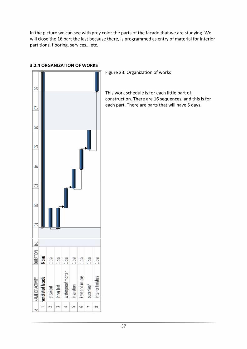
In the picture we can see with grey color the parts of the façade that we are studying. We
will close the 16 part the last because there, is programmed as entry of material for interior
partitions, flooring, services… etc.
3.2.4 ORGANIZATION OF WORKS
Figure 23. Organization of works
This work schedule is for each little part of
construction. There are 16 sequences, and this is for
each part. There are parts that will have 5 days.

38
3.2.5 HUMAN SAFETY
This work is classified as hazardous because the job is in high. the best solution is to work
with a scaffold equipped with skirting board and double-rail as a collective protection. As a
individual protection, workers should use harness, work clothes, gloves, protective boots
and helmet. the worker has to know how lifting weight in the correct way. If the job is
cutting some material, worker must to use protective glasses. The electrical devices must be
in perfect conditions and grounded.
3.2.6 MACHINES, MATERIALS AND TOOLS
NAME UNIT QUANTITY
MACHINES
drill screw u 1
radial saw u 1
MATERIALS
Lightweight blocks 30x19x19 u 4940
Panel of polyurethane m2 304.98
Panel adhesive l 29.05
Cement mortar M 2,5 m3 13.94
Waterproofing cement mortar m3 2.9
Cement mortar M 5 m3 4.35
Plaster paste m3 4.35
Ceramic tiling m2 290.46
Plastic coating m2 290.46
TOOLS
trowel to flat u 1
level u 1
trowel u 1
carrycot u 1
paint roller u 1
3.2.7 QUALITY CONTROL
We must to check before built that the materials correspond to those specified in the
control plan or, case, the specification the project.
They have the documentation required.
They are characterized by properties required.
They have been tested, where established in the program Control.

39
During the execution we will check:
-State of the support, the collapse or deviation from flatness should be able to be offset by
the set of joints in brackets.
-Stakeout and position of the brackets and modulation according to the project
specification.
-Check that the brackets are well calculated, which are placed according to project.
-Check distance between brackets, flatness, alignment (tolerance ± 1 mm / m) and
horizontal joint (> 2 mm per m).
-Check that the insulation covers the entire outer face of the support wall and the resistant
structure of the building and check its thickness.
-Check that the width of the horizontal and vertical joints between tiles or plates, meet the
tolerance established in the project.
-Check that the building expansion joints coincide with a vertical board cladding system by a
double bracket.
-Check the execution in accordance with construction details of the project or system (leaks,
waste water, etc.)
Upon completion of the ventilated facade they will be visited thereof, in order to verify that
specifications are met dimensional established in the project.
3.2.8 SOME DETAILS
Figure 24. Facade
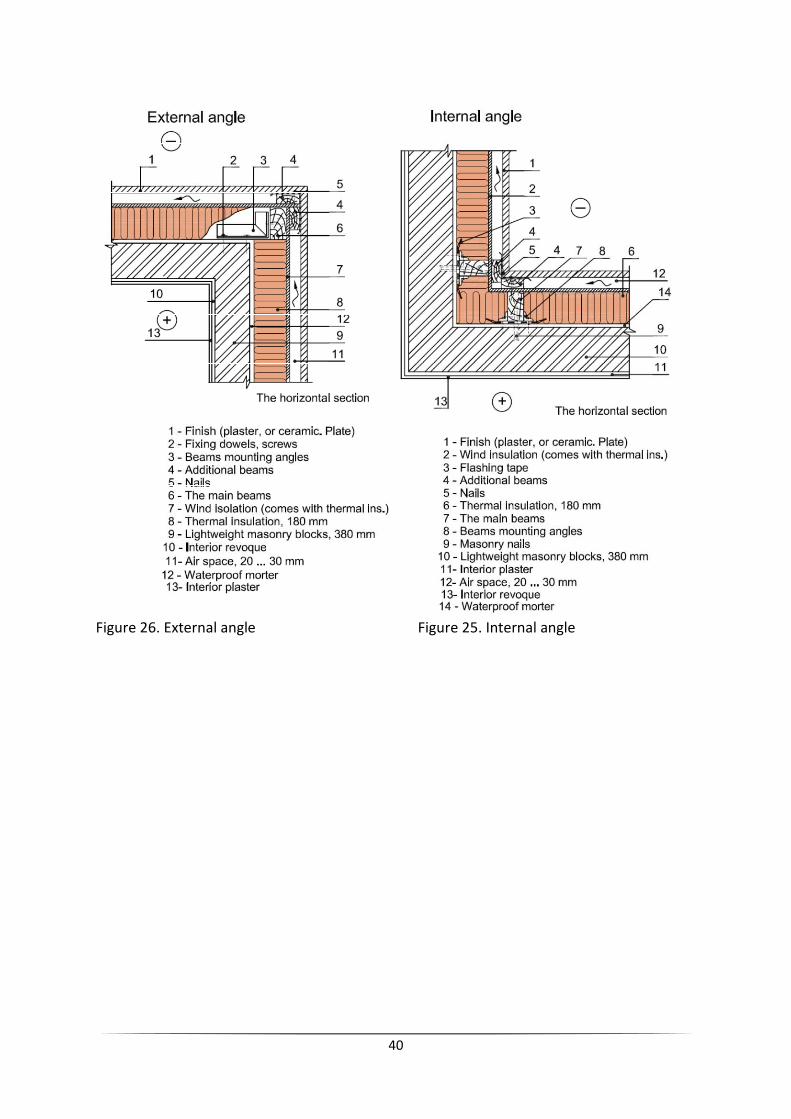
40
Figure 26. External angle Figure 25. Internal angle

41
Figure 26. 3D of facade layers

42
3.2.9 BUDGET
Main sheet enclosure composed of 380 mm thick, made
of lightweight blocks with plaster mortar waterproofing of 1.5 cm
thickness by its outer side, no thermal insulation based hydrophilic
polyurethane sheets of 180 mm thickness, coatedon the outside
with ceramic tiling placed with mechanical fasteners corrosion resistant, with
ventilated air chamber through the joints of the cladding and
the interior plaster trim and finished with thin plastic coating,
including formation oflintels and jambs, execution meetings, special items and
received structural work, considering a 3% loss and a 20% shrinkage of mortar.
m2
price amount
1º official of construction 2,5 h 21,8 54,5
Regular peon of construction 2,5 h 21,2 53
Lightweight blocks 30x19x19 17 u 0,6 10,2
Panel of polyurethane 1,050 m2 42,93 45,08
Panel adhesive 0,10 l 11,46 1,15
Cement mortar M 2,5 0,048 m3 69,36 3,33
Waterproofing cement mortar 0,01 m3 144,46 1,44
Cement mortar M 5 0,015 m3 102,68 1,54
Plaster paste 0,015 m3 149,44 2,24
Complementary direct costs 0,03 89,61 2,69
Ceramic tiling 1 m2 99,98 99,98
Plastic coating 1 m2 4,67 4,67
279,82
measurements 290,46 m2 81.276,51 € 280403,98 LTL
3.2.10 TECHNICAL ECONOMICS INDICATORS
Quantity of works: 290.46 m2
Installation costs: 81.276,51 € = 280403,98 LTL
Duration of works: 90.76 days ≈ 91 days
Wage of 1official of construction: 90.76 x 8 h = 726.15 h -- x 21.8 € = 15830.07 € or
54613.74 LTL
Wage of peon of construction: 90.76 x 8 h = 726.15 h -- x 21.2 € = 15394.38 € or 53110.61
LTL

43
4. ORGANIZATION PART
4.1 MASTERPLAN
4.1.1 DESCRIPTION
In the plan of building lot is intended:
-The main machines working places and moving tracks
-Storages and storing sites positions
-Temporary electricity, water-supplying, sewerage and fireplug, positions
-Safety and dangerous zones
-Temporary access roads and passages
-Temporary buildings positions
The plan of building lot is preparing before starting constructional works. The lot is on
planning, trees, which are impeding, are cutting of, the soil is pushed aside and stored. All
the site preparation has to be made according to construction organizing project. The
building lot is surrounding by fence. The working zone of crane and dangerous zones are
marked. On the preparation stage, it is necessary to do these works:
-To prepare temporary building for workers
-To cut trees which are in the building zone
-To make a entrance to work place
-To prepare storage sites
All temporary buildings will be supplied by electricity. The building site will be supplied by
electricity from the transformer substation, where is the main electricity distributional and
accounting lock and cable.
The bathroom temporary building will be supplied by water, and will need sanitary
installation.
4.1.2 SELECTION OF TOWER CRANE
Calculation of technological parameters of tower crane.
First of all the following parameters of installing building have to be known:
1. The dimensions of building and location (underground and over-ground parts).
2. The weights, dimensions and location of installing constructions.
3. The work conditions (the peculiarities of building site, soil characteristics, the
peculiarities of underground structures).

44
First of all, you must check if crane technical characteristics match the inequalities:
Qk >QR.
Hk >HR.
Lk>LR
Here:
Qk – the ascension power of selected crane, t
QR – the required ascension power, t
Lk - the reach of selected crane boom, m
LR - the required reach of crane boom, m
Hk - the lifting height of selected crane hook, m
HR – the required lifting height of hook, m
The technological parameters of crane are calculating according to the building
characteristics. The required crane is selecting according to the tables of technical
characteristics of cranes.
Tower crane selection when the underground and over-ground works are fulfilling
like in the future building.
First of all, using the next, formula the required height of hook lifting is determining:
HR = h1 + h2 + h3 + h4 = 13.50 + 2 + 0.5 + 3.5 = 19.50 m.
Figure 27. Characters of formulas

45
Here (figure 27) :
h1 – the height of abutment (support), on which the installing element is bracing, which is
calculating from the under-crane track or the bottom of support, m
h2 – the height of installing element, m
h3 - free interval between abutment (support) and installing element (0.5 – l m)
h4 – the height of hitching (trailing) equipment (strops) above the installing element, m.
Then the ascension power of crane is calculating using the next formula:
QR = P + Pstr = 3 + 0.15 = 3.15 t
Here:
P - the weight of heaviest lifting construction, t
Pstr- the weight of hitching (trailing) equipment (strops), t
If crane will install only the over-ground construction such as our crane, the reach of boom
will be determinated according to formula:
LR = l + ba + 3bpk2 5
Here:
l - the distance from the marginal support of under-crane track to the building, m
ba - the width of over-ground part of building together with balconies and bow-windows, m
bpk - the width of under-crane track or supports, m
And:
l = 3R - bpk2 5 + (0.7 − 1)
here R – the radius of crane platform turn.
We know l = 2.5 m, so:
LR = 1 + 35.6 + (3.8/2)= 38.5 m
When the values of LR, HR and QR are calculated, the crane could be selected
using the diagrams of the tower crane. The diagrams show, that the selected crane
50 EC-B5 LIEBHERR, match all requirements.
Qk = 5 t > QR = 3.15 t
Hk = 42,1 m > HR = 19.50 m
Lk = 45.4 m > LR = 38.5 m
You can see the crane information in the next website:
http://www.liebherr.com/CC/en-GB/region-(europe)/products_cc.wfw/id-12481-
0/measure-metric

46
DETAIL OF BASE OF CRANE
Figure 28. detail base of crane
4.1.3 SETTING OF DANGEROUS ZONE
During the installment works in some parts of the construction site, in bars,
workplaces, and crossings the dangerous areas are appearing. In construction such
areas are known as dangerous zones. In the beginning of construction works and
during construction, dangerous zones in which constantly arise or may arise risk
factors should be determined. The dangerous zones are dividing into two groups:
1. Dangerous zones, in which dangerous and or hazardous factors constantly affect
the processes.
2. Dangerous zones, in which dangerous factors could appear.
1. Dangerous zones, in which dangerous and or hazardous factors constantly affect
the processes, are:
- Near the electrical equipment with non-insulated parts electric current (flow)
(Table 1);
- Fenceless zones at a height when height difference is 1.3 m and the higher;
- Places where hazardous wastes and or the concentration of harmful substances in
workplace air may exceed the limit values.

47
Voltage, kW Distances, limiting the dangerous zone from
the fenceless uninsulated parts of the electrical equipment or from
the vertical plane, which is the nearest power line wire, with
a projection on the land, m
< 1 1,5
1 ÷ 20 2,0
35 ÷ 110 4,0
150 ÷ 220 5,0
330 6,0
500 ÷ 750 9,0
800 (current) 9,0
Table 1. The boundaries of dangerous zones were the influence of electric current
(flow) could appear.
The boundaries (limits) of dangerous zones, were appear the risk factors of
harmful substances exceeding should be determined by measurements.
2. Dangerous zones, in which dangerous factors could appear, are:
- near buildings under construction and assembling (or dismantling) building
structures or equipment;
- places over which the structures or equipment installation (or dismantling) works
are executing;
- places over which a loads are lifting and transporting by cranes;
- places where the machinery, their parts or work equipment are moving.
This group of dangerous zones is determining by evaluating the possible fall
distance of lifted element, which depends on the lifting height (Table 2).
The lifting height of
element, m
The minimum possible fall distance of lifted element, m
When the element lifted
by crane
When the thing (item) falls
from the structure (building)
< 10 4 3,5
< 20 7 5
< 70 10 7
< 120 15 10
< 200 20 15
< 300 25 20
< 450 30 25
Table2. Determination of the fall distance of lifted element.
Dangerous zones, close to the moving parts of machinery and equipment is 5 m
from them, if there is no more strict or additional requirements in instructions of
machinery and equipment manufacturers.

48
Dangerous zones, which are constantly affected by danger and (or) nuisances,
must be enclosed by fences that stops the workers with no right of access to such
areas.
Dangerous and hazardous areas must be fenced and marked by signal warning
signs or otherwise clearly marked. The dangerous operations must be authorized.
The determination of crane dangerous zones
The limits of dangerous zones areas, where there is transfer of elements is
performing by cranes, are determining by calculation the sum (the total distance)
of horizontal projection of lifted element, the maximum dimension (length) of
biggest element and it’s possible fall distance.
The limits of dangerous zones near structures are determining by summarizing the
maximum dimension (length) of biggest installed element and it’s possible fall
distance.
The limits of dangerous zones for construction planning (general plan) are
recommended to determine by following:
rlPRdangerous ++=
Here (figure 29):
r - possible fall distance of the biggest lifted element, m. (see Table 2)
P – the reach of crane boom ( reachR) and a half of lifted element length (or
maximum dimension), measuring in meters and calculating according to formula:
2
lRP reach +=
Here:
l – the biggest lifted element, m
So:
P = 33 + 3/2 = 34.5 m
R = 34.5 + 3 + 5.5 = 43 m
The figure below shows how to determine the dangerous zone for crane, as well as
graphically visible dimensions needed to summarize.

Figure 29. The determination of
Will be considered the next risks:
-Presence of obstacles.
-Areas of way.
-Jobs in proximity to high voltage power lines.
The prevention measures, for the first four are specifications established on the
basis of the following legal texts:
-Royal Decree 836/2003 of 27 June, approving a new Technical Instruction
"MIEAEM2" Regulations Lifting and handling equipment, referring to tower cranes
for construction or other applications.
-Royal Decree 1215/1997 of 18 July laying down m
by workers in teams.
It should be borne in mind also that through Article 5 of the ITC
is established in the UNE 58
strength and safety removable crane w
what we have for each of the assumptions made as follows:
49
The determination of crane dangerous zones
Will be considered the next risks:
Jobs in proximity to high voltage power lines.
The prevention measures, for the first four are specifications established on the
legal texts:
Royal Decree 836/2003 of 27 June, approving a new Technical Instruction
Regulations Lifting and handling equipment, referring to tower cranes
construction or other applications.
Royal Decree 1215/1997 of 18 July laying down minimum safety and health for use
It should be borne in mind also that through Article 5 of the ITC-MIEAEM2, binding
established in the UNE 58-101 - 92, Part 2: Lifting heavy equipment. Terms of
and safety removable crane works. Conditions of installation and use with
have for each of the assumptions made as follows:
The prevention measures, for the first four are specifications established on the
Royal Decree 836/2003 of 27 June, approving a new Technical Instruction
Regulations Lifting and handling equipment, referring to tower cranes
inimum safety and health for use
MIEAEM2, binding
92, Part 2: Lifting heavy equipment. Terms of
orks. Conditions of installation and use with

50
Presence of obstacles
In paragraph 7.3 of the UNE 58-101-92, states: "The vertical clearance between the
pen and the last area of movement of personnel shall be 3 m minimum. If the load
or empty hook passes within 3 m of the area, will be necessarily placed on it
enough to prevent the indicators of his approach.
This means that when the crane weathervane turn must respect the next
distances:
Figure 30. Horizontal and vertical obstacles
As you can see, we are not inclined to use signaling and also taking into account
the flexibility of these structures, we have considered a minimum distance
between the tip of the arrow and the nearest obstacle of 2 m Walkways in
paragraph 4.1 of the UNE 58-101 92 states: "The minimum clearance for the
passage of personnel, among the most prominent parts of the crane and any
obstacle is 0.60 m wide and 2.50 m high. In case of failure application of this
condition will prohibit the access of staff to this area dangerous”. Figure 30, 31
Figure 31. Safety distances

51
Obstacles in proximity of high voltage power are lines referenced in paragraph 4.1 of
the UNE 58-101-92, states: “At no time any part of the crane and its suspended loads,
can enter contact with power lines. If these lines are high voltage power should exist
between these lines and these items a safe space of 5 m, as minimum, measured in
horizontal projection”. Figure 32
Figure 32. Distance with electrical services
We can see below the section of the building with the position of the crane, and below of
this picture is the position in aerial view.
Figure 33. Position of crane with cross section

52
Figure 34. position and radio of crane
4.1.4 TEMPORARY ROAD
Temporary roads in the building places are used to bring construction materials , etc.
Temporary roads are built combining with existing roads to reach warehouses, work
places, machines and etc. outside the building place. In our building site is 6 meters of width
and 21.7 meters of length.
4.1.5 TEMPORARY STORAGE BUILGINGS AND SITES
We have in the construction site two storage buildings of (4.80 m x 2.40 m), and an
uncovered area of 35.7 m². That places are enough to keep all storages and stockpiles of
materials, little machinery, etc.

53
4.1.6 TEMPORARY BUILGINGS
To satisfy our needs we will put in our construction site three workers buildings of (4.80 x
2.40 x 2.60 ) m, one management office of (3.70 x 2.40 x 2.60) m, one temporary toilet and
shower building of (4.80 x 2.40 x 2.60) m.
Knowing the number of workers that are working simultaneously we can calculate the
number of temporary buildings.
We will can leave these buildings when the interior of our building will be habitable. We put
one or more areas for functions performed by temporary buildings.
ROOMS AND TOILETS NEEDS
Before starting the work 2 m2 / Worker with minimum height of 2.30 m.
Banks, lockers, racks and so on.
Toilets and showers 1/10 Workers.
Mirrors 1/25 Workers Length = safety clothing.
Toilet 1.00 x 1.20 m and H = 2.30 m 1/25 men workers and 1/15 women workers separated.
You can rent a room in other building.
Drain.
Information: http://www.consmetal.es/casetas-de-obra.html
4.1.7 TEMPORARY BUILGINGS
We will need a temporary electricity supply installation with counter to electric company.
Mostly of works will need electricity to be done. For example tower crane needs electricity
continuously.
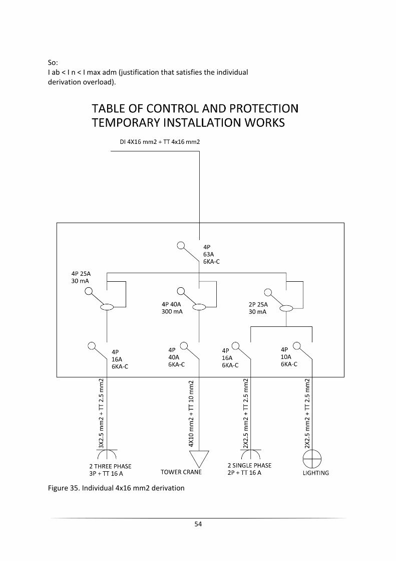
Our installation will be of an individual 4x16 mm² derivation.
Justification of individual 4x16 mm² derivation
P=/3.u.i.cos f
Where:
P = Power in W
U = Voltage in volts for three-phase system as is in the case 400V
I = intensity in A.
cos f = power factor (in Spain is considered 0,9)
I max adm = maximum admissible intensity in A.
I= 40 A
I= 63 A (intensity of the protection element) (the switch of the box)
I max adm= 80 A according to rebt itc-bt 19 tabla 1 (Spanish rules
REBT 02)
54
So:
I ab < I n < I max adm (justification that satisfies the individual
derivation overload).
Figure 35. Individual 4x16 mm2 derivation

55
4.1.8 CONSTRUCTION SITE LIGHTING
To calculate the number of luminaries necessary for the correct illumination of the
work, is used the following formula:
N= E×A∅n ×Fu ×Fm
Where:
N: Number of luminaries required.
E: Average luminance in lux.
∅n: Flow Rate of the lamp in lumens.
Fu: Factor of use.
Fm: maintenance factor.
A: Local Area
The surface of the work area is 1678 m², to be illuminated with an average illumination of
15 lux, with 1x150 W metal halide lamps, which produce a luminous
flux of 10,000 lumens per lamp. Will be used a normal maintenance factor 0.95.
Data from the lighting area are:
Length: 54.00 m.
Width: 37.00 m.
Height: 4.50 m
Index: K =(l × b)/h(l+b) = 1678 / 4.5 (37 + 54) = 6
With this index, and media with colors for floors and ceiling, and clear to the walls, is a
factor in initial use in direct lighting luminarie 1.
N= 15×167810000 ×1 ×0.95 =2.6 ≈3 lamp
Thus the number of lamps required for proper lighting of the premises is:
By calculation we have obtained, the need to place a minimum of 3 lamps.
4.1.9 TEMPORARY WATER SUPPLY
Of course will be needed a temporary water supply for our works. Will be installed a
general accountant in the building fence connected to the water supply rush of the city
placed close to the road.
The future temporary water supply line will require an accountant, stopcock general,
pipe tube 32mm in diameter (is the standard diameter in Spain), wash step and tap.

56
All the things mentioned before, are shown below.
Figure 36. Temporary water supply scheme
4.1.10 TEMPORARY SEWERAGE
The sewer construction will consist in removing water from rain and the elimination of
waste water as a showers, basins and toilets.
Drainage is connected to the network of urban wastewater.
The drainage plan consists in connecting our network to existing networks of the city.
The sewerage system will have a diameter of 200mm.
4.1.11 FENCE OF CONSTRUCTION SITE
The building fence will be a normal translucent fence of wire ideal for construction by the
rapid assembly and disassembly solving the problem of delimitation of solar work or works.
Fence height will be 2 meters. Will be needed 170.85 m for all the perimeter.
Information: http://www.rivisa.com/ficha_producto.html?cnt_id=28&ver_id=79
4.1.12 GENERAL REQUERIMENTS OF LABOR SAFETY
List of hazardous jobs in our construction:
-Working crane
-Work with hand tools and power machinery
-Welding
-Work excavators

57
-Working at heights
-Roof and façade installation
-Formwork installation
-Reinforcement and concrete works
-Installation works
- Building area is surrounded of 2m high wire mesh fence.
- Fence encloses crane dangerous and work area.
- In construction site is being installed fire fighting shield with fire extinguishers,
crowbars, shovels, buckets, box with sand.
- All persons in the construction site must wear protective helmets.
- For doing a work is being used only scaffolding and ladders of inventory.
- In a construction site is being installs fire hydrant.
- The fence of the construction is being posted with signs about imminent danger
and is informing that unauthorized persons entering to the construction site is
prohibited strictly.
- All work is being made as is required in technological requirements.
- Construction contractor before work informs employees with safe working
conditions.
-Also is determined the danger zones, they are marked with highly visible warnings.
- Give the permits for work in dangerous zone limits.
- Develop a list of hazardous work in a construction site.
- If weather conditions are bad - cancel all work.
- Workers locations should be installed out of dangerous zones.
- Check whether the tools and appliances which are being used for work, complies all
standards.
- For each employee for service should be given a helmet, gloves, shoes with metal
ends, working clothes, safety glasses.
- Construction rubbish should be disposed of in appropriate locations.
- Transport and traffic routes must be maintained in good order, not loaded
with constructions, the road surface must be cleaned.
- Ladders, scaffolding must comply with all safety requirements - if the scaffolds
are unsteady, it should be attached with the rope to the still surface. After
installation check the connections on the fasteners. If there are traffic routes
near, should be installed roofs, facades and scaffolding covered with net.
- Scaffolding and ladders are being viewed every 10 days.
- Work at a height where protection is rope, should work qualified worker.
-Dig trenches in sandy soils without reinforcement is possible only up to 1.25 m.
- Raising Material or construction crane, used pallets, straps, measures preventing
the lifting objects to fall.
- It is prohibited to walk under raised structures or materials.
- Constructions which are raised should be well fortified.
- Should be installed fences witch to prevent falls, it may be marked.
- When it is break time, construction or materials shall be prohibited to leave.
- Before the roof, the supervisor must check supporting structures and enclosures;
the workers must be equipped with safety equipment.
- The materials can be packed on the roof only in the places where allows technical
project and ensure that they are falling.

58
GENERAL PROTECTION. SAFETY LABOUR
NAME NUMBER
Helmet Each worker
Security gloves Each worker
Protective clothing against mechanisms Each worker
Protective footwear Each worker
Protective glasses Each worker (depending of job)
First Aid Kit One kit
Vessel with drinking water and disposable cups One kit
4.1.14 REQUIREMENTS OF ENVIRONMENTAL PROTECTION
Will not be able in construction site bury waste the rubbish. When construction
work is completed, is required to remove construction waste, unnecessary soil,
clean up area and plant the plantations.
If any of these works on time of year can´t be competed, they should be finished in
the next season of planting.
4.1.15 REQUIREMENTS OF FIRE PROTECTION
During construction, will be followed rules about fire protection - construction
works and installation of fire protection rules.
In the future construction site in a visible and accessible place should be a panel
with inventory: two buckets, two axes, two crowbars, ladders, hook, 0.5 of sand
box, two fire extinguishers and two spades.

59
4.2 ORGANIZATION
4.2.1 TABLES OF MACHINERY AND WORKFORCE
60
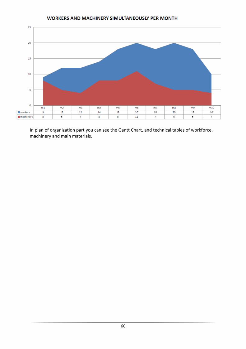
In plan of organization part you can see the Gantt Chart, and technical tables of workforce,
machinery and main materials.

61
BILIOGRAPHY
Websites:
Liebherr webpage
www.liebherr.com
Construction fences
www.rivisa.com
Storage buildings
www.consmetal.es
Valencia Base Data of construction website
http://www.five.es/basedatos/Visualizador/Base12/index.htm
Plasterboards website
www.knauf.es/knauf/controller/controller.jsp
Forum soloarquitectura
www.soloarquitectura.com
Spanish construction standards
www.codigotecnico.org/web
Polytechnic university of Valencia
https://poliformat.upv.es/portal
Construction details
http://detallesconstructivos.cype.es/
Books:
-How to Design Concrete Structures using Eurocode 2/ A J Bond, O Brooker, A J Harris, T
Harrison, R M Moss, R S Narayanan, R Webster.
The Concrete Centre, 2006
-Apuntes de construcción de estructuras de hormigón armado / Pascual Urbán Brotóns.
San Vicente (Alicante): (Imp. Gamma), D.L. 1999
-Construcción de estructuras : hormigón armado : detalles constructivos y perspectivas
Pascual Urbán Brotóns
Alicante: Club Universitario, 2001
- Construcción de estructuras de hormigón armado
Urbán Brotóns, Pascual. Alicante: Club Universitario , 1999
-Construcción de estructuras. Hormigón armado : adaptado a las instrucciones EHE,
EFHE, NCSE-02 y CTE. Urbán Brotóns, Pascual
San Vicente, Alicante: Club Universitario , 2009
-Construcción de estructuras : hormigón armado : detalles constructivos y perspectivas
Urbán Brotóns, Pascual
San Vicente, Alicante: Club Universitario , 2009


![SummaryMap ward2 [Converted] · 2019-10-01 · MU-2 MU-6 MU-16 MU-14 MU-6 MU-2 MU-20 MU-9 MU-4 MU-13 MU-15 MU-13 MU-16 MU-18 MU-22 MU-19 MU-16 MU-27 MU-4 MU-3A MU-17 MU-13 MU-4](https://img.dokumen.tips/doc/110x75/5f5e4f591750d150e9633369/summarymap-ward2-converted-2019-10-01-mu-2-mu-6-mu-16-mu-14-mu-6-mu-2-mu-20.jpg)