Embed Size (px)
Citation preview

CONSTRUCTION DESIGN
OBJECT: ASTRONOMICAL OBSERVATORY
LOCATION: ........................................................................................................................................
INVESTOR: ........................................................................................................................................
DESIGN OFFICE: Obserwatoria Astronomiczne ScopeDome sky observatory ul. Jaśminowa 29, 76-200 Słupsk
DESIGNED BY:
architect, Aleksandra Narkowicz-Pala, MSc
civil engineer Wojciech Chaciński, MSc
electrical engineer Zbigniew Wójcik, MSc
_________________________________________________________________________Słupsk, 30 Jan 2009
1

CONTENTS
TITLE PAGE...............................................................................................................1
LIST OD CONTENTS.................................................................................................2 PRIMARY NOTES:................................................................................................3
TECHNICAL CHARACTERISTICS........................................................................5
ATTACHEMENTS.................................................................................................8• STEEL LIST• REINFORCEMENT LIST• TG PANEL SCHEME• TG PANEL LIST• TP PANEL SCHEME
TP PANEL LIST
DRAWINGS :......................................................................................................15
1. FUNDATIONS 1:25
2. GROUND FLOOR 1:25
3. CEILING I 1:25
4. CEILING II 1:25
5. OBSERVATORY LEVEL VIEW 1:25
6. DOME VIEW 1:25
7. VIEW LOOKING DOWN 1:25
8. A-A SECTION 1:25
9. B-B SECTION 1:25
10.CONSTRUCTION DETAILS
11. GROUND FLOOR – ELECTRICAL INSTALLATIONS 1:25
12.OBSERVATORY – ELECTRICAL INSTALLATIONS 1:25
13.ELEVATION VIEWS 1:65
14.REINFORCED CONCRETE STAIRS
15.STEEL STAIRS
2

PRIMARY NOTES
1. Rules of adaptation.
This ready-to-use engineering specification is distributed under public licenseagreement allowing free use, copy and change for non-profit reasons, including buildingpermit.
Commercial use requires a permit issued by desing office: "ObserwatoriaAstronomiczne, ScopeDome sky observatory ", ul. Jaśminowa 29, 76-200 Słupsk,kom.: +48 602136289, tel.:+48 59 8410191, www.scopedome.com.
In most situations this projects requires to be adapted to local conditions as well as to locallaw regulations.
2. Allowed changes.
Any design engineer is allowed to prepare mirror version of this design as well as tointroduce following changes, without asking for an author permit:
• change of foundations or ground floor level• floor height• stairs or other communication fittings• ceiling type• wall structure • colors and finish• installations
• change of windows or doors
3

TECHNICAL CHARACTERISTICS
3. Subject of elaboration.
Hereby engineering specification contains a construction design for a small astronomicalobservatory building.
4. Site conditions.
Water table is assumed to be below foundation level and the grounds at foundation basehave supportive ability. Assumed base compression (base failure) is 150 kPa.Foundation level at 1,0 m below field level around the building. The foundation shall beadapted to local conditions considering water table and ground sustainability.
5. General description.
The building performs technical function, in a form of a square base supporting anastronomical dome. Observatory is served remotely and automatically. Technical room is placed at ground floorlevel, containing peripheral fix-up of the telescope. The interior of cupola constitutes realobservatory. Access on level of cupola through external stairs. Object does not require constant staff.
4. Basic data.
Surface of building 34,30 m2
Usable area of building: 47,30 m2
Gross floor area: : 56,35 m2
Cubature: 136 m3
5. Zestawienie pomieszczeń.
4
no
0.1 TECHNICA ROOM 20,3
1 OBSERVATORY 2,7
2 TERRACE1 9,2
3 TERRACE 2 15,1TOTAL: 47,3
room name area (m2)

6. General structure characteristics.
Designed building is one-storeyed, with no basement. It has masonry structure. On thebuilding, partly at ceiling level, the masonry base is designed to carry precast 3,0mdiameter astrodome, made of synthetics (manufactured by ScopeDome).The foundation consists of reinforced concrete strips, 30 cm high and 40cm wide,reinforcement is 4#12, and Ø6 each 30cm. The structure of reinforced concrete columnbase - according to drawing descriptions.Designed foundation walls structure made of concrete blocks, width 24cm, with outerstyrofoam insulation panels, 5-8 cm thick. The walls above the ground masonry made ofaerated concrete blocks, with outer styrofoam insulation panels, 10 cm thick, coated withthin external plaster. Pier column and pier foundation 60x60cm and 40x40cm made of reinforced concrete,reinforcement #12, according to drawing descriptions. The beams made of poured concrete: P1 24X0 cm, P2 24X24 cm. The lintels are precast(L-19 lintels). The ceilings construction: reinforced concrete slabs, poured. The slabthickness is 12cm, downside wire-mesh reinfocement: #8 each 20 cm, upper side wire-mesh reinforcement Ø6 each 20cm.External stairs made of reinforced concrete, poured, stair slab width is 12 cm. Technicalstairs onto terrace made of streel with precast steps.
7. Finish.
Internal coatings of calcium-cement plaster. The ceiling in the upper part: undersidefinished with waterproof gypsum plate. The upper ceiling slab shall be insulated. It is notrecommended to use gypsum plasters. Internal floors made of anty-glide tiles or PCV.Terrace covered with anty-glide tiles, color: light gray or light blue. Railings made ofrustless steel or rustproof steel coated with anti-rust paint. The railings shall be mounted toslabs by HILTI anchors.Windowsills, sheet facings made of coated tinplates, light gray or light blue colors.
8. Coloring.
External walls coated with external plaster (eg. silica), sand or ivory color. Wall plinth and wall fragments coated with roughcast, gray or beige color. Woodwork – designed window openings filled with glass-block, blue-gray or transparent.Door made of PCV or aluminum, thermally insulated, white.
9. Protections.
Steel elements shall be protected against rust – cleared and then painted 2-3 x with anticorrosive paint and primary ground, if necessary. Protection of wood elements –impregnate with complex chemical preparation against fire, fungi and insects. 10. Thermal and humidity characteristics.
The building has simple structure. It was assumed to be locate in I climate zone (Mid andEastern Europe area). The objects has no permanent heating system, but can be
5

equipped in an optional emergency electrical heater (for electronic devices protectionagainst low temperatures and frost).Thermal penetrability coefficient is 0,29 W/K*m2 for walls and 0,50 W/K*m2 for non-insulated ceiling.
11. Installations
Ventilation by gravity – air flow through stairs and astrodome. Electric energy supply frommain electric connection outside the building. Rainfall onto field outside the building. Theobject does not require any sanitary fittings.
11.1. Energy supply cable 0,4kV.The observatory is to be supplied from a cable line, its parameters shall be adapted tothe distance from main power supply connection outside the observatory.
11.2. Panel boards.Control panel TG and TP placed as on drawing no E-04 and E-05. Panel boardsequipment based on TH-35 rail (e.g. HAGER). The boards shall be mounted in nichesinside walls, with upper side at 1,8 m over the floor. Fittings according to scheme no E-01,E-02.
11.3. Lights, outlets 230 V and 400 V.Internal electrical installations by YDY cable placed under plaster. Sockets (with protectionbolt) placed at approx. 30cm over floor. The sockets placed on a central pier column shallbe mounted at the column surface. Wiring towards pier shall be placed inside floor inflexible PCV protecting pipes.
11.4. Anti-shock protection.All installations are equipped with electric shock protection. Additional protection supportsautomatic disconnection system. The system consists of differential switches Idn=0,03Aand excess switches. The receiving installation is based on TN-S pattern. All wiring from separation point PENrequires N conduit insulation. Careful wire insulation is required when connecting lightingfittings All one-phase outlets/sockets shall be bipolar and have protective bolt.
The main equalizing rail shall be placed close to control panel TG. The rail shall beconnected to observatory equipment made of metal, which normally are not under voltage.Equalizing cables made of copper LY10mm2 w RVS 18 p/t. Main rod shall be grounded.
11.5. Lightning rod installation.
The necessity of installing a lightning conductor depends upon local conditions and shallbe determined by an electrician. Electric installation shall be shielded as a protection incase of thunder.
11.6. Calculations.
Control panel TP – first floor
no Fitting name Installed power Pi (kW)
G1 outlets 230V 2,0G2 outlets 230V 2,0
6

M engine 2,0G4 outlets 230V 2,0O1 Lighting 0,2
total Pi 6,2TP control panel peak power:
Psz=∑kj*Pikj=0,7Psz=0,7*6,2kW=4,3kWIsz=Psz/(1,73*U*cosφ)=4,3kW/(1,73*0,4*0,93)=6,7 A
1. TP Panel protection – insulated breaker switch with safety catch 20A. Wiring fromTG to TP by conduit YLY5x4mm2.
2. Voltage decrease at cable entry :
δu=100∗P∗l
γ∗S∗U2=
100∗4,3kW∗103∗5m
54∗m
mm2∗4mm
2∗ 400V 2
=0,1
Control panel TG – ground floor
no Fitting name Installed power Pi (kW)
G1 outlets 230V 2,0G2 outlets 230V 2,0G3 outlets 230V 2,0GE1 Electric heater socket 2,0GE2 Electric heater socket 2,0O1 Lighting 0,2
total Pi 10,2TG control panel peak power:
Psz=∑kj*Pikj=0,6Psz=0,6*10,2kW=6,1kWIsz=Psz/(1,73*U*cosφ)=6,1kW/(1,73*0,4*0,93)=9,5A
TG Panel protection – insulated breaker switch with safety catch 20A.
Total power
Total peak power:Psz=kj*(PszTP+PszTG)zakłada się kj=0,8Psz=0,8*(4,3kW+6,1kW)=8,3kW
Peak current of observatory supply conduit:Isz=Psz/(1,73*U*cosφ)=8,3kW/(1,73*0,4*0,93)=12,9A
Wiring and protection calculations Permissible conduit sizes and their max protection charge limits (according to PN-IEC60364-5-523:2001 standard):
7
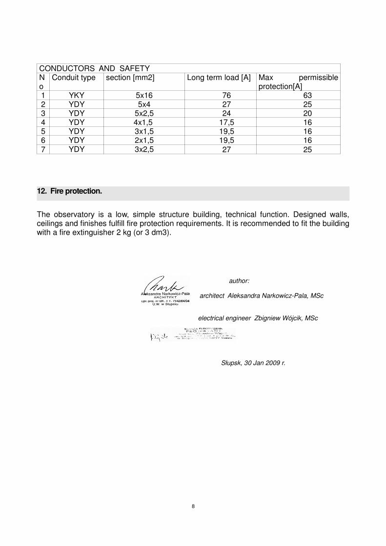
CONDUCTORS AND SAFETY No
Conduit type section [mm2] Long term load [A] Max permissibleprotection[A]
1 YKY 5x16 76 632 YDY 5x4 27 253 YDY 5x2,5 24 204 YDY 4x1,5 17,5 165 YDY 3x1,5 19,5 166 YDY 2x1,5 19,5 167 YDY 3x2,5 27 25
12. Fire protection.
The observatory is a low, simple structure building, technical function. Designed walls,ceilings and finishes fulfill fire protection requirements. It is recommended to fit the buildingwith a fire extinguisher 2 kg (or 3 dm3).
author:
architect Aleksandra Narkowicz-Pala, MSc
electrical engineer Zbigniew Wójcik, MSc
Słupsk, 30 Jan 2009 r.
8

9
steel element list
NR PROFILlenght quantity weight 1m weight 1item
weight
total
mm item kg/m. kg kg
1 side beam of steel stairs 2300 2 26,60 61,18 122,36
CHANNEL IRON 220
2 precast steel step width 240mm lenght 1000mm 1000 8 - - -
3 stell railings L=35,88 mb 358800 1 - - 0,00
total kg 122,36
handrail Ø 50

10
reinforcem ent list
LENG
HT
DIA
METE
R
TOTAL LENGHT- running m etresELEMENT QUANTITY total
ROD NO by quantity
elem ent
Ø cm item item Ø6 A-0 #8 A-III #12 A-III #10 A-III #16 A-III
1 12 3000 4 4 120,0
2 6 108 100 100 108,0
6 12 150 4 4 6,0
item 1 4 6 200 5 5 10,0
3 12 225 6 6 13,5
4 6 164 19 19 31,2
item 1 5 6 164 19 19 31,2
1 12 290 4 4 11,6
2 6 126 13 13 16,4
item 1
1 10 333 4 4 13,3
2 6 66 19 19 12,5
item 1
1 12 500 4 4 20,0
2 16 531 5 5 26,6
item 1 3 6 91 60 60 54,6
2 6 78 15 15 11,7
7 12 330 2 2 6,6
8 12 344 2 2 6,9
item 1
1 12 2020 4 4 80,8
2 6 78 68 68 53,0
item 1
1 10 950 4 4 38,0
item 1 2 6 72 32 32 23,0
1 8 2830 13 13 367,9
2 8 1640 13 13 213,2
3 6 115 19 19 21,9
3 6 223 16 16 35,7
4 8 336 6 6 20,2
item 1 5 8 289 6 6 17,3
1 8 268 7 7 18,8
2 8 286 26 26 74,4
3 8 622 15 15 93,3
4 8 477 2 2 9,5upper
w ire-
mesh 6 286 33 33 94,4
item 1
upper
w ire-
mesh 6 622 17 17 105,7
1 8 222 15 15 33,3
2 8 488 13 13 63,4
item 1 3 8 228 13 13 29,6
4 8 486 12 12 58,3upper
w ire-
mesh 6 228 30 30 68,4
upper
w ire-
mesh 6 486 25 25 121,5
12 20 2 2 4,8ANCHORS M12 (steel
stairs)4 item 12 24 2 2 5,8
ANCHORS M10
(dom e)14 item
10 20 16 16 32,0
TOTAL m . 746,1 999,3 329,0 83,3 26,6
WEIGHT 1m kg 0,22 0,39 0,89 0,62 0,89
w eight by diameters kg 165,52 394,09 291,93 131,44 53,01
STEEL TOTAL kg
BEAM W2
COLUMN SŻ 2 40X40
item 1
LENG
HT
DIA
METE
R
STRIPS
TOTAL LENGHT- running m etresNAME
ELEMENT
1036,0
SPOT FOOTING 80X80 FOR PIER & COLUMN
SŻ 2
COLUMN SŻ 1
BEAM P1
UPPER SLAB
STAIRS
COLUMN SŻ 2 60X60
BEAM P2
BOTTOM SLAB
BEAM W1

11

TG Control Panel element list, ground floor:
symbol Name Descrription Quantity manufacturer
1 EN 145 transitional relay, 12/24V, 5A, 1P (with LED) 1 HAGER
F1 L73H Breaker switch, insulated, D02, 3 x 63A 1 HAGER
F2 L73H Breaker switch, insulated, D02, 3 x 63A 1 HAGER
F3 MB110A Excess breaker/switch, 6kA, B, 1-polar, 10A 1 HAGER
F4 MB110A Excess breaker/switch, 6kA, B, 1-polar, 10A 1 HAGER
F5 CD426J Differential switch 25A, 30mA, 4-polar, AC type 1 HAGER
F6 MB110A Excess breaker/switch, 6kA, B, 1-polar, 10A 1 HAGER
F7 MB110A Excess breaker/switch, 6kA, B, 1-polar, 10A 1 HAGER
F8 MB110A Excess breaker/switch, 6kA, B, 1-polar, 10A 1 HAGER
F9 CD426J Differential switch 25A, 30mA, 4-polar, AC type 1 HAGER
F10 MB110A Excess breaker/switch, 6kA, B, 1-polar, 10A 1 HAGER
F11 MB110A Excess breaker/switch, 6kA, B, 1-polar, 10A 1 HAGER
H1 SVN127 Signal lamp, triple, red 230V AC 1 HAGER
K1 ES220 Contact 230V, 2Z/25A 1 HAGER
P1 EG071 7-day digital clock//timer, 1P/16A. 1 mod. 1 HAGER
Q1 HA402 overcharge breaker switch, modular, 4-polar, 40A 1 HAGER
Q2 SPN415 over voltage shield switch, C, 4-polar, TN-Scabling
1 HAGER
12

13

TP Control Panel element list:
symbol Name Descrription Quantity manufacturer
F1 MB110A Excess breaker/switch, 6kA, B, 1-polar, 10A 1 HAGER
F2 CD426J Differential switch 25A, 30mA, 4-polar, AC type 1 HAGER
F3 MB110A Excess breaker/switch, 6kA, B, 1-polar, 10A 1 HAGER
F4 MB110A Excess breaker/switch, 6kA, B, 1-polar, 10A 1 HAGER
F5 CD426J Differential switch 25A, 30mA, 4-polar, AC type 1 HAGER
F6 MM509N Engine switch 4,0-6,3 A 1 HAGER
H1 SVN127 Signal lamp, triple, red 230V AC 1 HAGER
Q1 SB440 breaker switch, modular, 4-polar, 40A 1 HAGER
Q2 SPN415 over voltage shield switch, C, 4-polar, TN-Scabling
1 HAGER
14

BB
A
A
civil eng. Wojciech Chaciński
ARCH-STRUCTUREELECTRICITY
CONSTRUCTION
DATA:
1:2501/2009BK.II.F.7342/64/94, PO-0343
POM 0161/POOK/03, POM BO/0076/04 DESIGNOBSERVATORY
AN 8346/172/86, POM/IE/5424/01
arch.Aleksandra Narkowicz-Pala FOUNDATIONS 1
electr. eng. Zbigniew WójcikLICENSE:
LICENSE:
LICENSE:
ARCHITECTURE:
STRUCTURE:
ELECTRICITY:
40 439 40
12
40 143 35 2 80 179 40
40 439 40
60
40439
40247
5
40179
80180
40124
6122
40439
40119
5
29187
1060
10188
29
12 240 239 12
635
763
12239
239
12
503
132
503
524
198
820
7222
245
24 150 15 20210 60 10 188 24
5 24 230 24 201 24
5 24 206 20 229 24 5
503
STOPA BETONOWA
STOPA BETONOWA
2
1
3
A B C
SŻ2 60x60
SŻ1 20x20
foundation grounding made of steel band 25x4conduted vertically min. 5cm over foundation bottom
earth outlet from foundations d. 3. c`a 2m
FOUNDATION LEVEL: 1,0 mBELOW GROUND AROUNDTHE BUILDING
FOUNDAMENT STRIPS ANDSPOT FOOTING:CONCRETE B20STEEL A-III (34GS), A-0 (St0S)
FOUNDAMENT WALLS:CONCRETE B20OR CONCRETE BLOCKS WITHEXTERNAL STYROFOAMINSULATION th. 5cm

Lk
(73
)
250
150
Dz
110
205
BB
A
A
DATE: 2GROUND FLOOR
civil eng. Wojciech Chaciński
ARCH-STRUCTURE
CONSTRUCTION
1:2501/2009BK.II.F.7342/64/94, PO-0343
POM 0161/POOK/03, POM BO/0076/04 DESIGNOBSERVATORY
arch.Aleksandra Narkowicz-PalaLICENSE:
LICENSE:
ARCHITECTURE:
STRUCTURE:
132
612
2
5
34 455 34
238 161 124
5
773
4925
7625
7625
7625
7625
292
5
523
10 12 240 239 12 10
645
1012
239
239
137
7
41 25 79 25 79 25 79 25 79 25 41
10 24 198 60 198 24 10
34 261 194 33
10 24 7 223 24 201 34
455
455
34
523
250
1024
197
6019
724
132
5015
073
2562
2561
2517
3411
57
455
204
2422
7
-0,03
-0,01
±0,00=
-0,03
NICHES IN STYROFOAMINSULATION;
KEEP SLOPE TOWARDSOUTSIDE
(DECORATION)CONCRETE BASE
24X40X30(underneath beam)
CONCRETE BASE24X40X30(underneath beam)
CONCRETE BASE(underneath beam)
WIRING NICHE-PREPARE DURINGCONCRETE POURING
PIER
A B
2
1
3
C
2xL19/150
2xL19/1
80
SŻ1 20x20
1,5%
P2 24x24
P1 2
4x3
0
SŻ2 60x60
P1 2
4x3
0
8X18,76/23
6X18,76/23
ENTRANCE
OBSERVATORY ENTRANCE
ELECTRICALPANEL BOARD
optional electric heater
opctional electric heater
ventilation "Z" typeunder the slabcanal pcv Ø 20
grille at both sidesPCV 15X20
EXTERNALL MASONRY WALLSMADE OF AIRED CONCRETE
EXTERNAL INSULATION- STYROFOAMPANELS thick 10cm
TECHNICAL ROOMTECHNICAL ROOMTECHNICAL ROOMTECHNICAL ROOM1111PCV/TILESPCV/TILESPCV/TILESPCV/TILESA: 20,3 m2A: 20,3 m2A: 20,3 m2A: 20,3 m2

BB
A
A
3CEILING I
civil eng. Wojciech Chaciński
ARCH-STRUCTURE
DATA:
1:2501/2009BK.II.F.7342/64/94, PO-0343
POM 0161/POOK/03, POM BO/0076/04 DESIGNOBSERVATORY
arch.Aleksandra Narkowicz-PalaLICENSE:
LICENSE:
ARCHITECTURE:
STRUCTURE: eachNSTRUCTION
24
140
297 182 34
249 24
286
10
10
10
10
50
3
47
7
12
47
91
2285
268
50
32
60
297
12 285 194
40
15
03
13
62
2
16
16
18
18
20
20
20
20
36
42
02
02
02
02
02
02
02
02
01
71
7
47
9
12 20 20 20 20 20 20 20 20 20 20 13 14 12 12 12 17 5
39 110 148
189
1010
82
30
12
20
20
20
20
20
20
20
20
20
20
16
42 25
54
25
5 42 3
25
12
51
5
23
04
22
40
12
2
10 278 115 120
KEEP DISTANCEBETWEEN COLUMNAND SLAB min. 1,5cm
WIRING NICHE
W1
W1 24x24
W1 24x24
W1 24x24
W1 24x24
PIER
P1
24
x3
0P
1 2
4x
30
W1 24x24
2
2xL19/150
P2 24x24
3
4
1
A B
2
1
3
C
26x Ø8 each 20cm, l=2860
5#8 each 10cm
3#8 each 1
0cm
2x
Ø8
ea
ch 2
0c
m,
l=4
77
0
7x Ø8 each 20cm, l=2680
15
x Ø
8 e
ach
20
cm
, l=
62
20
CEILING SLAB 1 - BOTTOM REINFORCEMENTS (upper reinforcement: wire-mesh rod Ø6 each 20 cm)
CONCRETE B20STEEL A-III (34GS) A-0 (St0S)
outline of wall on the slab
outline of wall on the slab
outline of wall on the slab
empty
outline of wall on the slab
#8 at the bottom, each 20cmslab thickness t=12cmb
eam break
NOTE- THE WALLS STAYING ONTO SLABS SHALL BEMADE OF LIGHT AERATED CONCRETEINSULATION- STYROFOAM 10cm thick

8 x 18,0 = 1,44 m
1 2 3 4 5 6 7 8
BB
A
A
4CEILING II
civil eng. Wojciech Chaciński
ARCH-STRUCTURE
1:2501/2009BK.II.F.7342/64/94, PO-0343
POM 0161/POOK/03, POM BO/0076/04 DESIGNOBSERVATORY
arch.Aleksandra Narkowicz-PalaLICENSE:
LICENSE:
ARCHITECTURE:
STRUCTURE: each NSTRUCTION
DATE:
233
235
522
250
20 20 20 20 20 20 20 20 20 20 20 10 10 10 10 20 20 20 20 20 20 20 20 20 20 15
523
10
222
486
486
10
228
275
10
19
10
10
10
10
10 272 207 24 10
207 42 5 202
1213
20
20
20
20
20
20
20
20
20
20
15
11
271
288 115 120
40
150
61
503
1213
20
20
20
20
20
20
20
20
20
20
14
13
20
20
20
18
18
18
18
18
18
18
18
18
18
12
132
503
115
TECHNICAL STEELSTAIR
WIRING NICHE
KEEP DISTANCEof min. 1,5cm
BETWEEN PIERAND SLAB
each NCRETEBASE24X40X30(underneath beam)
each NCRETEBASE
24X40X30(underneath beam)
W1 24x24
W1 24x24
W1 24x24
zarys ścianki na stropie
PIER
2xL19/180
P1 24x30
W1 24x24
W1 24x24
1
2
4
3
A B
2
1
3
C
P1 24x30
CEILING SLAB 2 - BOTTOM REINFORCEMENTS (upper reinforcement: wire-mesh rod Ø6 each 20 cm)
#8 at the bottom each 20cmslab thickness t=12cm
3#8 each 10cm
15x Ø8 each 20cm, l=2220
3#8 each 10cm
2#8 each 10cm
3#8 each 10cm
13x Ø8 each 20cm, l=4860
12x Ø8 each 20cm, l=4860
15x Ø8 each 20cm, l=2280
5#8 each 10cm
5#8 each 10cm
each NCRETE B20STEEL A-III (34GS) A-0 (St0S)
NOTE- THE WALLS STAYING ONTO SLABS SHALL BEMADE OF LIGHT AERATED CONCRETEINSULATION- STYROFOAM 10cm thick

Z1
135
80
DS
192
100
6 x 23,7 = 1,42 m
1 2 3 4 5 6
8 x 18,0 = 1,44 m
1 2 3 4 5 6 7 8
BB
A
A
5OBSERVATORY LEVEL VIEW
civil eng. Wojciech Chaciński
ARCH-STRUCTURE
CONSTRUCTION
1:2501/2009BK.II.F.7342/64/94, PO-0343
POM 0161/POOK/03, POM BO/0076/04 DESIGNOBSERVATORY
arch.Aleksandra Narkowicz-PalaLICENSE:
LICENSE:
ARCHITECTURE:
STRUCTURE:
DATE:
523
271
81
116
290
34
91
40
91
34
240 239
239
239
116 290 116
222
72 150
79
124
25
10 24 91 40 91 24 10
128 144 251
+2,60
+4,25
+2,60
+4,25
+4,25
R= 123,0
STEEL RAILINGS
H=1,10m
TECHNICAL STEEL
STAIRS
TECHNICAL STAIRS
LADDER TYPE OR
FOLDED
WIRING NICHE
AN INTERNAL SHELTER
UNDERNEATH
FLOOR
AN EXTERNAL SHELTER
FOR EQUIPMENT
UNDERNEATH TERRACE
CLOSED BY A FOLDING
AL SHUTTER
RAILING
H=1,10m
TABLICA
ELEKTRYCZNA
W2 24x20
W2 24x20
W2 24x20
W2 24x20
PIER 40x40
A B
2
1
3
C
TOWARDS GROUND
FLOOR
TOWARDS
OBSERVATORY TERRACE
TO OBSERVATORY
WALLS TO CARRY A DOME
RAISED ONTO SLABS, MADE OF
LIGTHTWEIGHT AERATED CONCRETE
EXTERNAL INSULATION - STYROFOAM 10cm thick
TERRACE 1TERRACE 1TERRACE 1TERRACE 12222TILESTILESTILESTILESA: 9,2 m2A: 9,2 m2A: 9,2 m2A: 9,2 m2
OBSERVATORYOBSERVATORYOBSERVATORYOBSERVATORY1111PCVPCVPCVPCVA: 3,5 m2A: 3,5 m2A: 3,5 m2A: 3,5 m2
TERRACE 2TERRACE 2TERRACE 2TERRACE 23333TILESTILESTILESTILESA: 15,1 m2A: 15,1 m2A: 15,1 m2A: 15,1 m2

6 x 23,7 = 1,42 m
1 2 3 4 5 6
BB
A
A
6DOME VIEW
civil eng. Wojciech Chaciński
ARCH-STRUCTURE
CONSTRUCTION
DATA:
1:2501/2009BK.II.F.7342/64/94, PO-0343
POM 0161/POOK/03, POM BO/0076/04 DESIGNOBSERVATORY
arch.Aleksandra Narkowicz-PalaLICENSE:
LICENSE:
ARCHITECTURE:
STRUCTURE:
269300
R=123,0
POSSIBLE FLAP
OVER STAIR OPENING
PIER
W2 24x20
W2 24x20
W2 24x20
W2 24x20
3. STEEL ANCHORS MADE OF SCREWED ROD Ø10-12,
PREVIOUSLY MOUNTED IN CONCRETE BEAM
ANCHOR A DOME AT MIN. 6 POINTS OF WALLS
- RECOMMENDED - AT 8 POINTS.
PREMISSED ANCHOR TYPES:
MINIMAL DIAMETER Ø10, MINIMAL ANCHOR DEPTH 15cm.1. PRECAST STRETCHER ANCHORS
2. SYSTEM PRECAST HILTI CONCRETE ANCHORS
HY 150+HAS-E M10x90/21
CIRCULAR BEAM
W2 24X20, REINFORCEMENT4#10, Ø6 each 30cm

BB
A
A
7VIEW LOOKING DOWNDATE:
civil eng. Wojciech Chaciński
ARCH-STRUCTURE
CONSTRUCTION
1:2501/2009BK.II.F.7342/64/94, PO-0343
POM 0161/POOK/03, POM BO/0076/04 DESIGNOBSERVATORY
arch.Aleksandra Narkowicz-PalaLICENSE:
LICENSE:
ARCHITECTURE:
STRUCTURE:
523
262 261
261
262
111
300
111
288 235
645
523
122
112 300 111
R=150,0
REVOLVING ASTRO DOME
MADE OF LAMINATE

civil eng. Wojciech Chaciński
ARCH-STRUCTURE
1:2501/2009BK.II.F.7342/64/94, PO-0343
POM 0161/POOK/03, POM BO/0076/04 DESIGNOBSERVATORY
arch.Aleksandra Narkowicz-PalaLICENSE:
LICENSE:
ARCHITECTURE:
STRUCTURE:
A-A SECTION 8
eachNSTRUCTION
DATE:
300
10 24 222 24 10
18
205
20
12
53
20
80
+4,65
153
728
100
415
73
240
±0,00
60
-0,03
152
30
83
20
235
12
85
140
25
-1,03
+2,60
+4,85
+4,12
73
+4,25+4,25
93
225
235
83
10
55
235
12
13
165
+4,50
18
80
412
38
+2,23
+3,88
-0,03
+2,47
73
27
208
12
153
SHEET FACING15cm wide
SHEET FACING15cm wide
W2 24x204#10
Ø6 each 0,3m
W1 24x244#12Ø6 each 0,3m
W1 24x244#12Ø6 each 0,3m
W1 24x244#12
Ø6 each 0,3m
SHEET FACING15cm wide
PLITH FINISH- ROUGHCAST
PROTECT WITHCEMENT ROUGH COATING
CONCRETE PAVER
LIGHT CONCRETE10cm thick
HORIZONTAL SEAL:2XDAMPPROFFING ASPHALT
VERTICAL SEAL:2xBITUMINOUS SEAL
ANCHORS FOR DOME
TINPLATE SHEET400X400X3
4xANCHOR FORTELESCOPE MOUNT
USE SEALANT AT RIM
DOME
114,2114,2 17,917,9
PIER
PIER
1 - 4#12
14
2890
3 - 4#12
2250
1490
6 - 4#12
14
terrain
terrain
FOUNDAMENT STRIPS AND SPOT FOOTING:CONCRETE B20STEEL A-III (34GS), A-0 (St0S)
FOUNDAMENT WALLS:CONCRETE B20OR CONCRETE BLOCKS WITHEXTERNAL STYROFOAM INSULATION th. 5cm
WALLS OVER GROUND - MASONRY MADEOF AIRED CONCRETE
WOODEN ELEMENTS LAYINGONTO CONCRETE SHALL BE PROTECTEDWITH PAPER OR FOIL
THE HEIGHT OF PIER ACCORDINGTO TELESCOPE TYPE
TECHNICAL ROOM
SHELTER
bottom level of shutter (window)
PCV COVERING, STICKED OR TILESCEMENT SLAB 4cm thick, LEVELED, REINFORCEDWITH WIRE-MESH1X PCV FOIL ON THE LOOSESTYROFOAM PANELS 5cm thick1X PCV FOIL ON THE LOOSE2xDAMPPROFFING ASPHALT OR FOIL, STICKEDLIGHT BETON SLAB, 10cm thickCONDENSED SAND FILLING 25cm thick
TILESCEMENT SLAB 4cm thick, LEVELED, REINFORCEDWITH WIRE-MESH1X PCV FOIL ON THE LOOSESTYROFOAM PANELS 5cm thick1X PCV FOIL ON THE LOOSE2xDAMPPROFFING ASPHALT OR FOIL, STICKEDREINFORCED CONCRETE SLAB, 12cm thickPLASTER
TILESCEMENT SLAB 4cm thick, LEVELED, REINFORCEDWITH WIRE-MESH1X PCV FOIL ON THE LOOSESTYROFOAM PANELS 5cm thick1X PCV FOIL ON THE LOOSE2xDAMPPROFFING ASPHALT OR FOIL, STICKEDREINFORCED CONCRETE SLAB, 12cm thickPLASTER
TILES2X LIQUID WATERPROFING FOILCEMENT SLAB 4cm thick, LEVELED, REINFORCEDWITH WIRE-MESH1X PCV FOIL ON THE LOOSESTYROFOAM PANELS 5cm thick1X PCV FOIL ON THE LOOSE2xDAMPPROFFING ASPHALT OR FOIL, STICKEDREINFORCED CONCRETE SLAB, 12cm thickPLASTER

civil eng. Wojciech Chaciński
ARCH-STRUCTURE
1:2501/2009BK.II.F.7342/64/94, PO-0343
POM 0161/POOK/03, POM BO/0076/04 DESIGNOBSERVATORY
arch.Aleksandra Narkowicz-PalaLICENSE:
LICENSE:
ARCHITECTURE:
STRUCTURE:
B-B SECTION 9DATE:
eachNSTRUCTION
+4,12
+2,23
+4,25
±0,00-0,03
-1,03
103
235
12
178
25
+4,50
-0,03
488
+4,85
177
25
+2,60
+3,88
5053
223
1083
1055
217
30135
1812
5320
80
+2,23
24
+2,17
93225
2195
38
3053
20395
512
13
100
238
250
+3,82
+2,47
SHEET FACING15cm wide
USE SEALANT AT RIMUSE SEALANT AT RIM
W2 24x204#10
Ø6 each 0,3m
W2 24x204#10Ø6 each 0,3m
W1 24x244#12Ø6 each 0,3m
W1 24x244#12Ø6 each 0,3m
W1 24x244#12Ø6 each 0,3m
SHEET FACING15cm wide
DECORATIVENICHE
LIGHT CONCRETE10cm thick
HORIZONTAL SEAL:2XDAMPPROFFING ASPHALT
PROTECT WITHCEMENT ROUGH COATING
VERTICAL SEAL:2xBITUMINOUS SEAL
SHEET FACING15cm wide
SHEET FACING15cm wide
ANCHORS FOR DOME
TINPLATE SHEET400X400X3
PIER
TILESCEMENT SLAB 4cm thick, LEVELED, REINFORCEDWITH WIRE-MESH1X PCV FOIL ON THE LOOSESTYROFOAM PANELS 5cm thick1X PCV FOIL ON THE LOOSE2xDAMPPROFFING ASPHALT OR FOIL, STICKEDREINFORCED CONCRETE SLAB, 12cm thickSTYROFOAM 5cm thickWATERPROOF GYPSUM PLATEPLASTER
PIER
DOME
TILESCEMENT SLAB 4cm thick, LEVELED, REINFORCEDWITH WIRE-MESH1X PCV FOIL ON THE LOOSESTYROFOAM PANELS 5cm thick1X PCV FOIL ON THE LOOSE2xDAMPPROFFING ASPHALT OR FOIL, STICKEDREINFORCED CONCRETE SLAB, 12cm thickPLASTER
TILES2X LIQUID WATERPROFING FOILCEMENT SLAB 4cm thick, LEVELED, REINFORCEDWITH WIRE-MESH1X PCV FOIL ON THE LOOSESTYROFOAM PANELS 5cm thick1X PCV FOIL ON THE LOOSE2xDAMPPROFFING ASPHALT OR FOIL, STICKEDREINFORCED CONCRETE SLAB, 12cm thickSTYROFOAM 5cm thickWATERPROOF GYPSUM PLATEPLASTER bottom level of shutter (window)
P1 24x30
P2 24x24
P1 24x30
SŻ1 20x204#12, Ø6 each 18cm
INTERNAL SHELTER EXTERNAL SHELTER
FOUNDAMENT STRIPS AND SPOT FOOTING:CONCRETE B20STEEL A-III (34GS), A-0 (St0S)
FOUNDAMENT WALLS:CONCRETE B20OR CONCRETE BLOCKS WITHEXTERNAL STYROFOAM INSULATION th. 5cm
WALLS OVER GROUND - MASONRY MADEOF AIRED CONCRETE
WOODEN ELEMENTS LAYINGONTO CONCRETE SHALL BE PROTECTEDWITH PAPER OR FOIL
THE HEIGHT OF PIER ACCORDINGTO TELESCOPE TYPE
PCV COVERING, STICKED OR TILESCEMENT SLAB 4cm thick, LEVELED, REINFORCEDWITH WIRE-MESH1X PCV FOIL ON THE LOOSESTYROFOAM PANELS 5cm thick1X PCV FOIL ON THE LOOSE2xDAMPPROFFING ASPHALT OR FOIL, STICKEDLIGHT BETON SLAB, 10cm thickCONDENSED SAND FILLING 25cm thick
terrainterrain
TECHNIOCAL ROOMTECHNICAL ROOM

civil eng. Wojciech Chaciński
ARCH-STRUCTURE
CONSTRUCTION
1:2501/2009BK.II.F.7342/64/94, PO-0343
POM 0161/POOK/03, POM BO/0076/04 DESIGNOBSERVATORY
arch.Aleksandra Narkowicz-PalaLICENSE:
LICENSE:
ARCHITECTURE:
STRUCTURE:
10DATE:CONSTRUCTION DETAILS
60
60
15
4
40
4
15
40
80
80
24
20
20
20
24
24
40
24
-1,03
-0,10
10
30
63 2
4
24
6#12
4#12
4#12
4#10
4#10
4#12
4#12 4#12
LIGHT CONCRETE10cm thick
ANCHOR Ø10FOR DOME MOUNT
WIRING NICHEapp. 15X4
WIRING NICHEapp. 15X4
HORIZONTAL SEAL:2XDAMPPROOF ASPHALT
VERTICAL SEAL:2-3xBITUMINOUS SEAL
sym.
3
555
28
55
28
49
49
4
1
2
55
29
29
size 80x80 size 20x20
4#12
5#16
60 Ø6
1
2
3
1 4#12 l=500 A-III500
13 Ø6 each 18cm
19 Ø6 each 18cm
2 5#16 l=513 A-III49312
3 l=91 A-026
30
1512
V1 P1 V2-1
9
0.0
-22
0.0
A
2 5#16
1 4#12
10x18
4x10
5
4x10
5 10x18
A-A
24 456 24
2460 Ø6
steel
sym.
6
29l=126
4#12 A-III289014
29
l=29041
2
3
4
5
13 Ø6 A-0
6#12 A-IIIl=2250 2250
19 Ø6
19 Ø6
l=164
l=164
28
49
28
49
A-0
A-0
Ø6 each 18cm, l=78
4
6
4#12 A-III
146 1490l=1504
55
14
17 2
1
rods
beam p2
shape
55
14
2
Ø6 each 30cm, l=78
Ø6 each 30cm, l=72
14
1
55
17 2
shape
Ø6 each 30cm, l=108
17
1
steel
26
23
55
1
2
rods
shape
55
17 2
17
l=3300
7
A-III7 3300
8
A-III
14 3300l=3440
2#12
8 2#12
CONCRETE B20STEEL A-III (34GS)
A-0 (St0S)
strip foundationbeam p1
size 24x24
circular beam W2
sym. rods
steel
size 24x24
main beam W1
column (pier) spot footing
column (pier) upper part column SŻ2 (pier) bottom part
size 24x30 size 30x40
size 40x40 size 60x60 size 24x20
column SŻ1
Ø6 each 18cm, l=66
19 Ø6 every 18cm


civil eng. Wojciech Chaciński
ARCH-STRUCTURE
CONSTRUCTION
1:2501/2009BK.II.F.7342/64/94, PO-0343
POM 0161/POOK/03, POM BO/0076/04 DESIGNOBSERVATORY
arch.Aleksandra Narkowicz-PalaLICENSE:
LICENSE:
ARCHITECTURE:
STRUCTURE:
13DATE:
ELEVATION VIEWS
SIDE VIEW
SIDE VIEW
FRO
NT VIEW
BACK VIEW

civil eng. Wojciech Chaciński
ARCH-STRUCTURE
CONSTRUCTION
1:2501/2009BK.II.F.7342/64/94, PO-0343
POM 0161/POOK/03, POM BO/0076/04 DESIGNOBSERVATORY
arch.Aleksandra Narkowicz-PalaLICENSE:
LICENSE:
ARCHITECTURE:
STRUCTURE:
14DATE:REINFORCED CONCRETESTAIRS
124 23 23
122 2
2
+2,60
-1,03
+1,47
1876
1876
2
24 201 24 230 24
235
127
30
73
235
12
841
30
70
30
106
12
2110
263
110
100
263
-0,03-0,03
+1,47
124
2
2
1876
1876
283
40
150
5 24 229 20
10 24 249
30
70
30
120
110
-1,03
-0,03
120 23 23
12
10
30
206
12
2
-0,01
W1 24x244#12Ø6 each 0,3m
W1 24x244#12
Ø6 each 0,3m
RAILING h=1,10mRUSTLESS OR RUSTPROOF STEELOR COATED WITHANTI-CORROSIVE PAINT
RAILING h=1,10mRUSTLESS OR RUSTPROOF STEELOR COATED WITHANTI-CORROSIVE PAINT
RAILING h=1,10mRUSTLESS OR RUSTPROOF STEEL
OR COATED WITHANTI-CORROSIVE PAINT
SHEETFACING15-20cm wide
CONCRETE STRIPBASE24X24
CONCRETE STRIPBASE24X24
#8 each 20cm, l=3360
#8 each 20cm, l=2890
#8 each 10cm, l=1640
#8 each 10cm, l=2830
Ø6 each 25cm, l=115
Ø6 each 25cm, l=115
5
6X18,76/23
880
70
5
4
1650
3
400
720
4
1240
50
1040
2550
2380
1
400
50
50
8X18,76/23
3
1,5%
1240
terrain
PAVER ONTO SAND -CEMENT FILLING(keep slope 1,5% towards ouside)
TILES2XLIQUID WATERPROOFING FOILCONCRETE SLAB 2cm thickPLASTER
TILES2X LIQUID WATERPROFING FOILCEMENT SLAB 4cm thick, LEVELED, REINFORCEDWITH WIRE-MESH1X PCV FOIL ON THE LOOSESTYROFOAM PANELS 5cm thick1X PCV FOIL ON THE LOOSE2xDAMPPROFFING ASPHALT OR FOIL, STICKEDREINFORCED each NCRETE SLAB, 12cm thickPLASTER
rods alternately
CONCRETE B20STEEL A-III (34GS), A-0 (St0S)
TILES2XLIQUID WATERPROOFING FOILCONCRETE SLAB 2cm thickPLASTER

civil eng. Wojciech Chaciński
ARCH-STRUCTURE
CONSTRUCTION
1:2501/2009BK.II.F.7342/64/94, PO-0343
POM 0161/POOK/03, POM BO/0076/04 DESIGNOBSERVATORY
arch.Aleksandra Narkowicz-PalaLICENSE:
LICENSE:
ARCHITECTURE:
STRUCTURE:
15DATE:STEEL STAIRS
+4,25
+2,60
24
18
22
15
12
6
6
191
15
204
16
25
RAILING h=1,10m
RUSTLESS OR RUSTPROOF STELL
OR COATED WITH
ANTI-CORROSIVE PAINT
SHEET FACING
PRECAST STEEL STEP
SIDE BEAM
CHANNEL IRON 220
USE SEALANT
2x SCREW M12 L=24
WITH TUBE
OR HILTI ANCHOR
2x SCREW M12 L=20
OR HILTI ANCHOR
9X18/24