Embed Size (px)
Citation preview

Constructing Customized Process Views
Rik Eshuis Paul Grefen
Eindhoven University of Technology, Department of Technology Management,P.O. Box 513, 5600 MB Eindhoven, The Netherlands
Abstract
To enable effective cross-organizational collaborations, process providers have tooffer external views on their internal processes to their partners. A process viewhides details of an internal process that are secret to or irrelevant for the part-ners. This paper describes a formal two-step approach for constructing customizedprocess views on structured process models. First, a non-customized process viewis constructed from an internal structured process model by aggregating internalactivities the provider wishes to hide. Second, a customized process view is con-structed by hiding and omitting activities from the non-customized view that arenot requested by the process consumer. The feasibility of the approach is shown bymeans of a case study.
Keywords: process views, business process management, business processintegration, dynamic service outsourcing
1 Introduction
In today’s networked society, more and more companies collaborate with eachother in a virtual way through the internet. Each partner in such a collabora-tion network has its own private business process. Coordination of these localbusiness processes takes place through the network. However, process-orientedcollaboration in a network can only occur if partners reveal some details oftheir business processes to the network. These revealed details can be capturedin an external or public view on the private business process [15]. A publicview is like a window through which the network can monitor the operationof an underlying private business process of a partner.
Email addresses: [email protected] (Rik Eshuis), [email protected] (PaulGrefen).
Preprint submitted to Elsevier Preprint 20 June 2007

Now, for each partner providing a process to the network, there is a tradeoff in the level of detail shown in the process view. On the one hand, if theprocess view reveals too few details of the underlying private business pro-cess, then the other partners of the network cannot effectively detect the localstate of the business process, which might prevent an effective operation ofthe network. For example, if some partner responsible for producing a cus-tomer made component does not reveal any details of its internal productionprocess, the main contractor cannot monitor the progress at the partner’s siteand therefore cannot coordinate the overall networked production process ina proper way. On the other hand, if the process view reveals all private de-tails, including business secrets, then the provider runs the risk of loosing itscompetitive edge. Other partners might copy then its way of working, turningfrom collaborators into competitors.
Moreover, other partners in the network might not be interested in every de-tail of the private provider process. Some details may be irrelevant for themor simply be noise in the business relationship. In the example of the pro-duction network given above, the main contractor is likely not interested indetailed information about the production process, but only in high-level sta-tus information. Thus, process views need to be customized to the needs ofthe partners, called the consumers.
This paper proposes a formal approach to construct a customized processview on a business process. The approach consists of two main phases. In thefirst phase, to ensure privacy and to protect ownership, a process providerconstructs a process view that hides private internal details of the underly-ing business process. The process view contains aggregate activities that hideinternal activities of the underlying internal business process. Such processviews are non-customized, so independent from the requirements of any spe-cific consumer. In the second phase, to filter out unwanted process information,a consumer constructs a customized process view, tailored to its needs. Thecustomized view reveals only those activities requested by the consumer; theremaining activities of the underlying process view are hidden or omitted.Though the first phase needs input from the provider and the second phasefrom the consumer, the actual construction of the views in both phases isdone fully automatically. The two-phase approach supports the interests ofboth providers and consumers.
We now explain these two phases, aggregation and customization, in moredetail, using the example in Figure 1. The internal, private process model isshown on the bottom while the customized process view is shown on the top. Inthe aggregation phase, the process provider first has to identify which activitiesof the business process have to be aggregated to hide private process details. InFigure 1, these activities to be aggregated are B and D, indicated with a doubleline. Next, the aggregate activity is constructed. This aggregate contains the
2

A
B C
E
D
F
A E FBCD
A E FBCD
A FBCDE
aggregation
customization
business process
non−customized process view
non−customized process view
customized process view
Fig. 1. Illustration of approach for generating customized process views
identified activities, but possibly also some additional activities, to ensure thatthe derived process view is consistent with the underlying process model. Inthe non-customized process view in Figure 1, activity C has been added to theaggregate BCD. We define the procedure for constructing aggregate activitiesboth declaratively (by construction rules) and operationally (by algorithms)and show the equivalence of both definitions. The declarative definition isuseful to explain computed aggregates to end users, while the operationaldefinition is more easy to implement. Finally, an external process view isconstructed by replacing the aggregated activities with the aggregate. Thesesteps can be repeatedly applied (not shown in the figure).
In the second phase, a consumer selects a set of activities that it wishes to seefrom the non-customized process view. In Figure 1 these activities are A andF, indicated with a double line. Next, fully automatically a customized processview containing these activities is constructed. All the other activities of thenon-customized process view are either hidden or omitted in the customizedview. In the customized view in Figure 1, unselected activities BCD and E
of the non-customized view are hidden by abstract activity BCDE. Figure 1illustrates the difference between the two phases. In the first phase, selectedactivities are aggregated, while in the second phase the unselected activitiesare hidden or omitted. Though this difference may seem small, it leads tocompletely different formal definitions, as shown in Sections 3 and 4.
Consumers can select the activities to be shown in the customized view by re-ferring to organization-independent activities, which could come for examplefrom industry standards like SCOR [31] or RosettaNet [29]. Providers can im-plement their own variant of such standard activities. To capture this, we use
3

an inheritance relation on activities, to indicate that an activity at a companyside inherits from (or implements) an abstract activity defined by an industrystandard. For example, a consumer can request compound RosettaNet activ-ity Request shipping order cancellation while the provider has implemented thisactivity as an activity Cancel order. The customized process view would thenshow Request shipping order cancellation instead of Cancel order. Using thisinheritance-based approach, adherence to reference models is easily obtain-able. In practice, this approach can be realized using ontologies [4].
In the remainder of this paper, we focus on block-structured process mod-els [12,20,23], or structured process models for short. In such models, eachblock has a unique entry and a unique exit point, and blocks are properlynested. If a structured process model is sequential, its structure is similar tothat of a structured program. Many existing process description languages,including industry standard BPEL [2] and OWL-S [24], are structured intoblocks. We show that the block-structure allows for a simple and efficient(tractable) procedure for constructing customized views. Block-structured pro-cess models have the advantage that they do not contain structural errors suchas deadlocks [20], for example the block-structure forbids that an OR split isimmediately followed by an AND join. However, some error-free processes can-not be easily modelled in a block-structured way. Extending the approach tounstructured, error-free process models is part of future work.
In sum, the main contribution of the paper is the definition of an approachthat helps process providers and consumers to construct tailored process viewson private processes in an efficient way, taking process standards into account.Providers can construct process views by hiding those parts of their businessprocesses that have to remain secret. Consumers can construct customized pro-cess views by hiding or omitting irrelevant parts of process views offered bythe providers. This allows an efficient setup of dynamic business-to-businesscollaborations with a strong process-orientation [13]. Examples of such col-laborations are virtual enterprises whose key operations are process-oriented,like logistics chains [14], financial and insurance networks [11], and industrialnetworks [9].
Structure. The remainder of this paper is organized as follows. Section 2defines structured process models. Section 3 defines the first phase of theapproach: how a non-customized view can be derived from a conceptual-levelprocess, given a set of nodes to be aggregated. The construction proceduredefines which nodes, next to the given nodes, need to be aggregated in orderto get a process view that is consistent with the conceptual process. Theconstruction procedure is defined both declaratively (by construction rules)and operationally (by algorithms) and the equivalence of both definitions isshown. Section 4 defines the second phase of the approach: how, given a set of
4
abstract activities that a consumer wants to be visible, a process view can becustomized to show only the relevant activities in full detail. The constructedcustomized view will contain concrete activities that are specializations of theabstract activities. As a case study, Section 5 applies our approach to theCrossWork project [17]. First, the the CrossWork architecture is extended tosupport the approach and next the approach is illustrated with a CrossWorkbusiness scenario. Section 6 discusses related work. Section 7 wraps up withconclusions and further work.
2 Preliminaries
We first define structured process models and then present an inheritancerelation on activities. We also give some auxiliary definitions that we use inSection 3.
2.1 Structured Process Models
Syntax. A process model specifies how a given set Act of activities (atomicunit of works) are ordered. The used ordering constructs are sequence, choice,parallelism, and structured loop. To simplify the exposition, we abstract fromdata.
Let P denote the set of all structured process models. A structured processmodel P ∈ P is a tuple (A,N, child, type, label) where
• A ⊆ Act is a set of activities,• N is a set of nodes,• child : N × N is a predicate that defines the hierarchy relation. We have
child(n, n′) if and only if n is a child (sub) node of n′.• type : N → {SEQ,PAR,XOR,LOOP,BASIC} is a function that assigns
to each node its type. Type SEQ indicates that all children of the nodeexecute in sequence, PAR that they execute in parallel, XOR that one ofthem is executed at a time, and LOOP that the children execute zero ormore times. We require that each SEQ, XOR, and PAR node has morethan one child and that each LOOP node has only a single child, which isno LOOP node. A node has type BASIC if and only if it is a leaf node,i.e. it has no children.
• label : N → A∪{τ} is a function labeling a node with an activity. Note thatthe same activity can label different nodes. The τ symbol is used to denotean aggregate activity, i.e., an activity in a process view that aggregates
5
activities from a lower level 1 .
We use an auxiliary function children : N → PN that defines for each nodeits set of child nodes. For a leaf node, this set is empty. The definition ofchildren makes use of predicate child:
children(n)df
= {n′ ∈ N |child(n′, n)}.
If c ∈ children(n), node n is parent of c, written parent(c). By children+ andchildren∗ we denote the irreflexive-transitive closure and reflexive-transitiveclosure of children, respectively. So children∗(n) = children+(n) ∪ {n}. Ifn ∈ children∗(n′), we say that n is a descendant of n′ and that n′ is anancestor of n. Note that each node is ancestor and descendant of itself.
To ensure that the child predicate indeed arranges nodes in a hierarchy, werequire that each node has one parent, except one node r, which has no parent.Next, we require that r is ancestor of every node in N . These constraintsensure that node are structured in a tree with root r. Leaves of the tree arethe BASIC nodes. Internal nodes have type SEQ, PAR, XOR, or LOOP .
To indicate the ordering of children of nodes of type SEQ, we use a partialfunction rank : N → N. The ranks of two nodes are only compared if thenodes share the same parent that has type SEQ. We require that two differentnodes with the same parent have different ranks, and that for a node n withl children, for any child c of n, rank(c) ∈ {0, . . , l − 1}. Using an overloadingof notation, we write rank(n, i), where 0 ≤ i ≤ l − 1, to indicate the uniquechild c of n for which rank(c) = i.
In the remainder of this paper, we will show structured process models graph-ically, using a variant of the UML activity diagram notation [32]. Figure 2shows the business process of a logistics organization that delivers cellularphones (GSM phones) from a warehouse to a customer. We use node contain-ment to indicate hierarchy. The root node is never shown. Sequence nodeshave an incoming and outgoing arrow crossing their border, whereas choiceand parallel nodes have a diamond and bar, respectively, on their border.Within a sequence node, the ordering relation is specified by means of arrows.Loop nodes have no dedicated symbol, but are indicated by drawing a selfedge for the unique child of the loop node. For example, in Figure 2 node Pick
GSM from stock is child of a loop node. To distinguish nodes from activities,in the remainder nodes are written in sans serif whereas non-τ activities arewritten in italic. To simplify the exposition, we assume in each example thatthe activity has the same name as the corresponding node.
1 The τ symbol comes from the field of process algebra, where it is used to denotean invisible action [25].
6

Get GSM
Get GSMserialnr
Wrap up parcel
Adjuststock
Deliver express
Hand overparcel
Determineregion
Determinetransport
Pick GSM from stock
Schedule route Deliver
Deliver parcel
Deliver regular
Fig. 2. Logistics process (adapted from [33])
Least common ancestors. To define the construction of process viewsin Section 3, we will make use of some auxiliary functions on the syntax ofstructured process models. The definitions are inspired by formal statechartsemantics [18,28].
For a set X of nodes, the least common ancestor (lca) of X, denoted lca(X)is the node x such that x is ancestor of each node in X, and every other nodey that is ancestor of each node in X, is ancestor of x:
• X ⊆ children∗(x), and• For every y ∈ N such that X ⊆ children∗(y), we have that x ∈ children∗(y).
Since nodes are arranged in a tree, every set of nodes has a unique least com-mon ancestor. For example, in Fig. 2 the lca of Deliver regular and Deliver ex-
press is Deliver, whereas the lca of Deliver regular and Hand over parcel is Deliver
parcel. Note that the lca of a single node is the node itself, i.e. lca({x}) = x.
Before relation. The before relation < denotes temporal ordering. Giventwo nodes n, n′ ∈ N , we have n before n′, written n < n′, if and only if
• node l = lca({n, n′}) has type SEQ, and• for the children cn, cn′ of l such that n is descendant of cn and n′ is descen-
dant of cn′ , we have rank(cn) < rank(cn′).
For example, in Fig. 2 we have Determine region < Deliver express.
7

Orthogonal relation. Given two nodes n, n′ ∈ N , we have n orthogonalto n′, written n⊥n′, if and only if n 6= n′ and the type of lca({n, n′}) is notSEQ. Since we require that a node of type LOOP has only a single child, ifn⊥n′ then their lca is either a PAR or a XOR node. For example, in Fig. 2we have Deliver regular⊥Deliver express.
2.2 Inheritance of activities
Above we introduced a set Act of activities. Let ≤ ⊆Act × Act be an in-heritance relation on activities. Given a, a′ ∈ Act, if a ≤ a′ than a is morespecific than a′ and a can replace a′, since a has all features of a′. For exam-ple, activity Handover parcel from Figure 2 inherits from SCOR [31] activityReceive and Verify Product at Customer Site. Relation ≤ is a partial order, soif a ≤ b and b ≤ a then a = b. We allow multiple inheritance, so it might bethat a ≤ b and a ≤ c yet b and c are incomparable, so b 6≤ c and c 6≤ b. Forexample, in SCOR [31] we have that activity Enable return is a specializationof both Enable and Return, but these activities are incomparable. Since ≤ is apartial order, the inheritance relation is acyclic, so an activity cannot inheritindirectly from itself.
3 Aggregation
This section defines the first phase of our approach: how process views canbe constructed from structured process models using aggregation. First, wedefine how a given set of nodes from the process model can be aggregated in acorrect way into a single node in the process view. Second, we define how, givena computed aggregate and a structured process model, a structured processview can be derived. These two steps can be repeated arbitrarily often, soa process view can itself be further aggregated into a more abstract processview.
3.1 Constructing aggregates
An aggregate is a set of nodes from the process model that is represented inthe process view by a single node n , i.e. node n hides the nodes containedin the aggregate. The user must specify which set of nodes has to be aggre-gated. However, the aggregate might need to contain some additional nodesas well, in order to get a process view that is consistent with the underlyingprocess model. The view and the process model are consistent if the orderings
8

CBA D
CBDAInconsistent view
Structuredprocessmodel
Fig. 3. Example to motivate Rule 2
of the process model are respected by the view and no additional orderingsare introduced in the view. We specify the consistency constraints as con-struction rules, to be satisfied by the constructed aggregated. Next, we definean algorithm for constructing aggregates. We show that both definitions areequivalent.
3.1.1 Construction rules
Let X be the set of conceptual-level nodes that have to be aggregated. Denoteby agg(X) the set of nodes that the aggregate constructed for X should containin order to derive a process view consistent with the underlying process model.
Rule 1 specifies the natural constraint that all nodes of X should be inagg(X):
Rule 1 X ⊆ agg(X)
The other rules are defined to ensure that after constructing the aggregate,the resulting process view is consistent with the underlying structured processmodel.
Rule 2 states that if two nodes x, y are aggregated such x is before y, thenevery intermediary node i, so x < i < y, should be contained in the aggregateas well. Otherwise, if an intermediary node i is not included, the aggregate willnot be atomic anymore in the process view. Then the aggregate will be on theone hand before agg(X), since x < i, but also after agg(X), since i < y. Forexample, aggregating in Figure 3 nodes B and D without aggregating C wouldresult in a view in which the aggregate is before and after C. Thus, a loop iscreated which is not present in the original model. Therefore, we require thati is included in the aggregate:
9
CBA D
X
Fig. 4. Example to motivate Rule 3
CBA D
X
CAB D
X
Structuredprocessmodel
Inconsistent view
Fig. 5. Example to motivate Rule 4
Rule 2 if x, y ∈ agg(X) and i ∈ N such that x < i < y
then i ∈ agg(X).
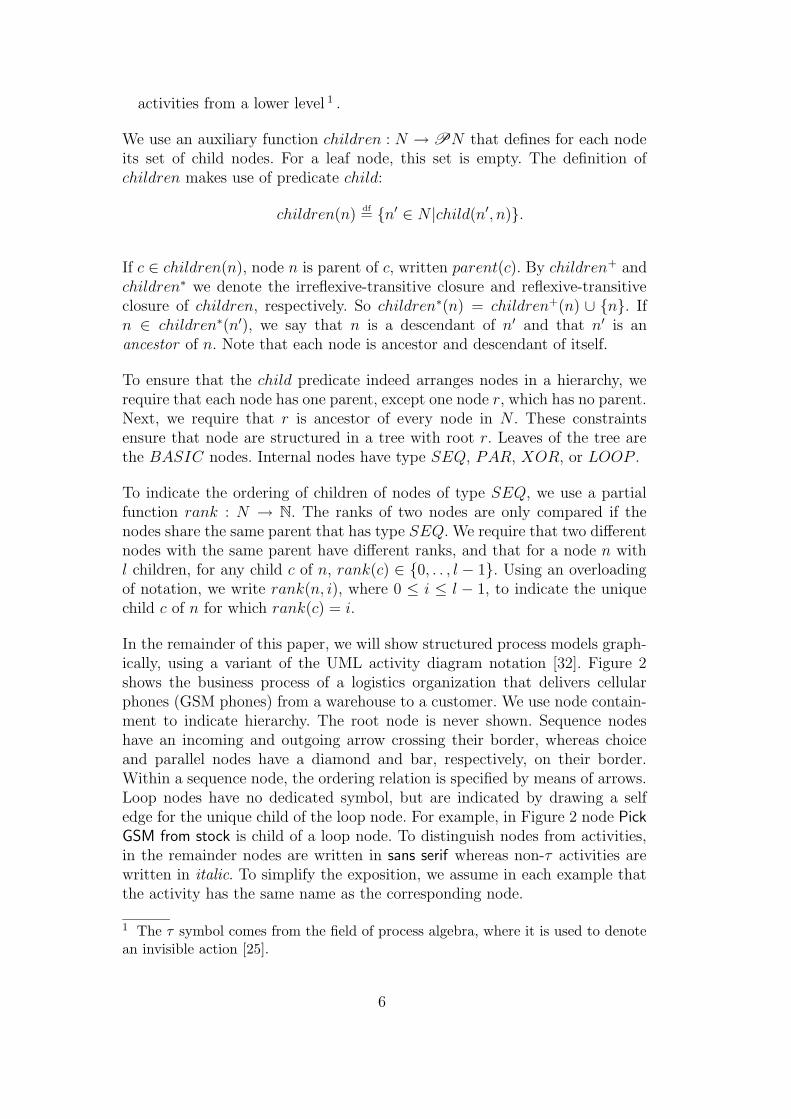
Rule 3 states that if a composite node is included in the aggregate, all itschildren are included as well. This ensures that in the process view aggregateshave no children, i.e. no internal details of the aggregate are revealed. Forexample, if in Figure 4 node X is to be aggregated, then B and C must beaggregated as well. Otherwise, the process view would be the same as theoriginal process, with X replaced by τ .
Rule 3 if x ∈ agg(X) then children(x) ⊆ agg(X).
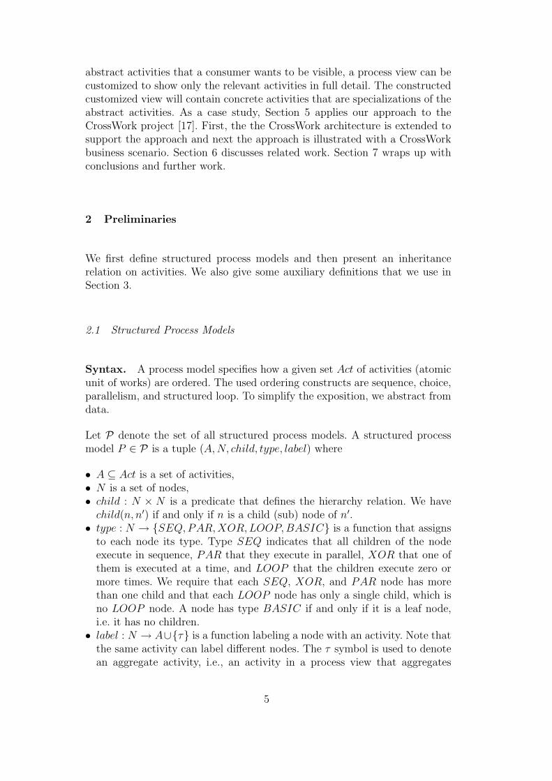
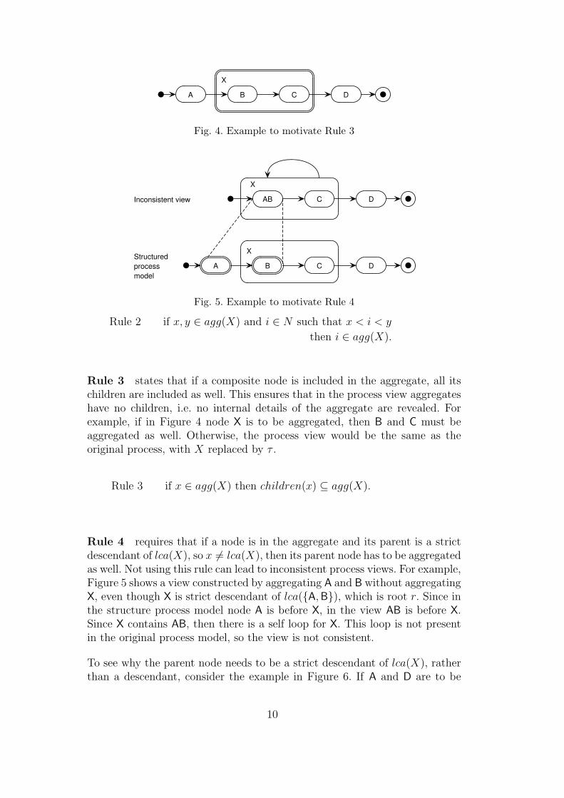
Rule 4 requires that if a node is in the aggregate and its parent is a strictdescendant of lca(X), so x 6= lca(X), then its parent node has to be aggregatedas well. Not using this rule can lead to inconsistent process views. For example,Figure 5 shows a view constructed by aggregating A and B without aggregatingX, even though X is strict descendant of lca({A, B}), which is root r. Since inthe structure process model node A is before X, in the view AB is before X.Since X contains AB, then there is a self loop for X. This loop is not presentin the original process model, so the view is not consistent.
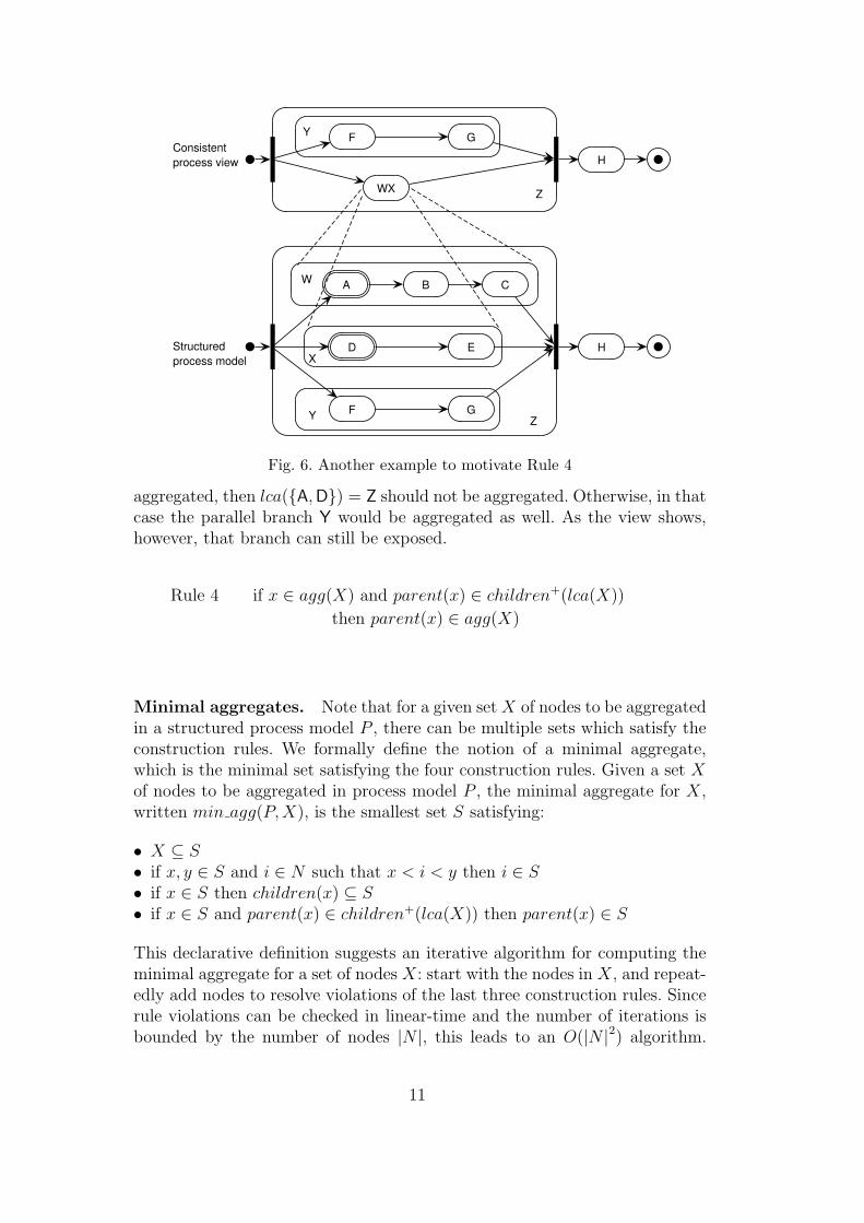
To see why the parent node needs to be a strict descendant of lca(X), ratherthan a descendant, consider the example in Figure 6. If A and D are to be
10
A
D
B C
E
W
X
Z
H
F GY
WX
H
F GY
Z
Consistentprocess view
Structuredprocess model
Fig. 6. Another example to motivate Rule 4
aggregated, then lca({A, D}) = Z should not be aggregated. Otherwise, in thatcase the parallel branch Y would be aggregated as well. As the view shows,however, that branch can still be exposed.
Rule 4 if x ∈ agg(X) and parent(x) ∈ children+(lca(X))
then parent(x) ∈ agg(X)
Minimal aggregates. Note that for a given set X of nodes to be aggregatedin a structured process model P , there can be multiple sets which satisfy theconstruction rules. We formally define the notion of a minimal aggregate,which is the minimal set satisfying the four construction rules. Given a set X
of nodes to be aggregated in process model P , the minimal aggregate for X,written min agg(P,X), is the smallest set S satisfying:
• X ⊆ S
• if x, y ∈ S and i ∈ N such that x < i < y then i ∈ S
• if x ∈ S then children(x) ⊆ S
• if x ∈ S and parent(x) ∈ children+(lca(X)) then parent(x) ∈ S
This declarative definition suggests an iterative algorithm for computing theminimal aggregate for a set of nodes X: start with the nodes in X, and repeat-edly add nodes to resolve violations of the last three construction rules. Sincerule violations can be checked in linear-time and the number of iterations isbounded by the number of nodes |N |, this leads to an O(|N |2) algorithm.
11

1: procedure Aggregate(P, X)2: l := lca(X)3: if l ∈ X then
4: agg := children ∗(l)5: else
6: C := {c ∈ children(l) | X ∩ children ∗(c) 6= ∅}7: aggC :=
⋃c∈C children ∗(c)
8: if type(l) = SEQ then
9: C ′ := {c ∈ children(l) | ∃a, b ∈ C : a < c < b}10: aggC ′ :=
⋃c′∈C′ children ∗(c′)
11: agg := aggC ∪ aggC ′
12: else
13: agg := aggC
14: end if
15: end if
16: return agg
17: end procedure
Fig. 7. Algorithm for constructing aggregates
Below we define a non-iterative, linear-time algorithm for computing minimalaggregates.
3.1.2 Algorithm
The algorithm Aggregate for constructing an aggregate is listed in Fig. 7. Itexpects a structured process model P and a set X of nodes to be aggregated,and returns an aggregate.
The algorithm first computes the least common ancestor l of the set X of nodesto be aggregated. If l ∈ X then all descendants of l need to be aggregated(l. 4). Otherwise, all children of l which have some descendant in X are putin set C (l. 6). Next, the set of all descendant of nodes in C are put in aggC
(l. 7). These descendants are to be contained in the aggregate by Rule 3 andRule 4.
Next, the type of l is tested (l. 8):
• If l has type SEQ, then the set C ′ of “intermediate” children of n arecomputed. Set C ′ contains a child c of n if and only if there are childrenc1, c2 ∈ C such that c1 < c < c2. The set of all descendant of nodes in C ′
is put in aggC ′ (l. 10). All descendants of these intermediate children of n
must be contained in the aggregate by Rule 2 and Rule 3. The aggregate istherefore the union of sets aggC and aggC ′ (l. 11).
• If l has type PAR or XOR, then the aggregate only contains all descendantsof C (l. 13).
12

CBA D
Z
BCA D
Z
Structuredprocessmodel
Process viewaccording to Rules 1−4
ZA DProcess viewaccording to Rules 1−5
Fig. 8. Example to motivate Rule 5
Finally, the constructed aggregate is returned (l. 16).
Note that computing the least common ancestor can be done in linear time [19].Using this observation, it is easy to see that the algorithm runs in O(|N |) time.
The correctness of the algorithm is shown by the following theorem, whichstates that the algorithm yields a minimal aggregate that satisfies all fourconstruction rules. The proof is in the appendix.
Theorem 1 Given a conceptual process model P and a set X of nodes to be
aggregated. Then min agg(P,X) = Aggregate(P,X).
3.2 Extension
Given a set X of nodes to be aggregated, the least common ancestor lca(X)is only aggregated if lca(X) ∈ X. Sometimes, this can lead to process viewswhich are correct, but counter intuitive. For example, aggregating B and C inFig. 8 according to the four construction rules results in the middle processview. Here, Z is not aggregated, because Z = lca({B, C}). All of the childrenof Z are aggregated, so Z only has a single child, which is the new aggregate.But in this case it would make sense to aggregate Z, since all of the childrenof Z are aggregated as well.
Therefore we define an additional rule, which states that if all children oflca(X) are included in the aggregate, node lca(X) itself should be included aswell.
13

Rule 5 if children(lca(X)) ⊆ agg(X) then lca(X) ∈ agg(X)
The algorithm needs to be modified slightly to take into account this newconstruction rule. Between lines 14 and 15, the following lines needs to beinserted:
if children(l) ⊆ agg then
agg := agg ∪ {l}end if
The theorem of the previous subsection can be easily extended to deal withthis new construction rule and the modified algorithm.
3.3 Generating process views
Above, we have outlined a declarative and operational approach for construct-ing an aggregate, which is a set of nodes that have be represented by a singlenode in the process view. Now we define a function gen : (P × N) → Pthat generates from a given structured process model and an aggregate theresulting process view, which is again a structured process model. If there aremultiple aggregates, the function can be repeatedly applied.
If agg is the constructed aggregate for process model P = (A,N, child, type, label),so agg ⊆ N , then the process model P ′ = gen(P, agg) is constructed by re-placing agg with a new node nagg 6∈ N that does not get any children in theprocess view P ′ and gets label τ .
Now the problem is that the new node nagg needs to be attached as child tosome node N \ agg, i.e., some node l ∈ N \ agg has to act as parent of nagg
in the process view P ′. Let l be the lowest node in N \ agg that is ancestor(in P ) of all nodes in agg. So agg ⊆ children ∗(l) and for every other nodel′ ∈ N \ agg for which agg ⊆ children ∗(l′), we have l ∈ children ∗(l′). Fromthe algorithm, it follows that if lca(agg) 6∈ agg then l = lca(agg); otherwise, l
is the parent of lca(agg) (l. 4). Thus, the construction procedure ensures thatnode l exists and is unique. Therefore, l can be the unique parent of nagg inP ′.
Formally, P ′ = (A′, N ′, child′, type′, label′) where
• A′ = { y | (x, y) ∈ label′ }• N ′ = N \ agg ∪ {nagg}• child′ = (child ∩ (N ′ × N ′)) ∪ {(nagg, l)}• type′ = type ∩ (N ′ × {SEQ,PAR,XOR,BASIC}) ∪ {(nagg, BASIC)}
14

Get GSM
Get GSMserialnr
Wrap up parcel
Adjuststock
Hand overparcel
Pick GSM from stock
Deliver parcel
Schedule & Deliver
Fig. 9. Example process view for Figure 2
• label′ = (label ∩ (N ′ × A)) ∪ {(nagg, τ)}
Instead of labeling the new aggregate node with τ , the user (provider) canalso decide to create a new activity. In the examples shown in this section,each aggregate of a consistent process view was labelled with a new activity,rather than τ .
Figure 9 shows the process view for Figure 2 if Determine region and Deliver
express are selected for aggregation.
4 Customization
This section defines the second phase of our approach: how constructed processviews can be customized. Input is a process view P ∈ P plus a set I of activitieswhich the consumer wishes to be visible for monitoring the progress of theprocess. We require that all activities in I are incomparable, so there are notwo activities such that one is descendant of the other. Output is a customizedview, which is again a structured process model P ′ ∈ P . In P ′ irrelevant partsof P with respect to I are omitted or hidden by aggregation. A part is irrelevantif none of the contained nodes executes an activity that implements someactivity in I. Not every activity i ∈ I needs to be implemented in P ′. However,the approach can be easily modified and extended to deal with additionalconstraints on, for example, the presence of activity implementations in the
15

customized view.
We define the customization algorithm declaratively as a function, customize :(P×PAct) → P , which transforms a structured process model P and a givenset I of activities into a structured process model customize(P, I) = P ′. Wenow define the individual components of P ′ = (A′, N ′, child′, type′, label′),given the input model P = (A,N, child, type, label).
The set A′ of activities contains the requested activities in I plus the activitiesfrom A that are actually used in the new labeling function label′, which isdefined later:
A′ = { a|a ∈ A ∪ I ∧ ∃n ∈ N ′ : (n, a) ∈ label′ }.
Before we define N ′, we provide some terminology. A node n is relevant ifone of its descendant nodes is labelled with an activity that implements anactivity i ∈ I:
relevant(n, I)df
⇔ there is a n′ ∈ children ∗(n) and i ∈ I : label(n′) ≤ i.
For example, for Figure 2, if I = {Determine Transport} then among othersnode Deliver parcel is relevant.
When customizing a process view, we have to ensure that each relevant nodein the process view occurs in the customized view, since the external partywishes to monitor relevant nodes. So all relevant nodes of P should be in P ′.The set of relevant nodes in the customized view is defined as:
N ′
rel = {n ∈ N | relevant(n, I)}.
Naturally, N ′ should contain N ′
rel. However, N ′ should also contain new ab-stract nodes, not in N , that hide irrelevant nodes in N . These abstract nodesare needed in P ′ to get a valid process view. For example, in the customizedview in Fig. 1 there is an abstract node BCDE that hides irrelevant nodes B,C, D, and E. Omitting BCDE would result in an invalid process view.
An abstract node only has to be created to hide the irrelevant children ofa compound node that also has relevant children. For example, in Figure 1the abstract node BCDE is created for compound node root r, which has bothrelevant and irrelevant children. If a relevant node has only irrelevant children,it needs no children in the customized view. If a relevant node has only relevantchildren, all these children are shown in the customized view. So in these lasttwo cases, an abstract child node is not needed.
16
The predicate relevant compound formally defines for which compound nodesof N an abstract child node needs to be created:
relevant compound(n, I)⇔ relevant(n, I)
∧ ∃n′ ∈ children(n) : relevant(n′, I)
∧ ∃n′ ∈ children(n) : ¬relevant(n′, I).
Note that relevant compound(n, I) is true implies n is compound, since onlycompound nodes have children.
We now define per type t of compound nodes, which concrete nodes of thisparticular type get a new abstract child in the customized view to hide irrel-evant children from the input model. These newly created nodes are put inset N ′
t . More precisely, if n ∈ N is a node such that relevant compound(n, I),then we denote by nt ∈ N ′
t a new (fresh) abstract node, so nt 6∈ N . In thecustomized view, nt hides all irrelevant descendants of n. However, not everyrelevant compound node n needs such a node nt. For certain types of nodes,irrelevant child nodes of a relevant compound node can also be completelyomitted, rather than being represented by some abstract node.
Before we define N ′
XOR, we observe that omitting irrelevant children froma relevant XOR node can result in a model with illegal states. For example,suppose for Figure 2 the external party wishes to monitor node Deliver express.Omitting in the customized process view Deliver regular would result in anillegal state at the external level if in the internal state Deliver regular wereexecuted. The external state would show that XOR node Deliver is performed,but the external party can also see that none of its children (i.e., Deliver express)is performed. So for the irrelevant children, i.e. Deliver regular, a new abstractnode must be created in the customized process view, say Other delivery, i.e.,non-express delivery. Therefore, for each relevant XOR node n a new abstractnode nxor is created, which leads to the following definition of N ′
XOR:
N ′
XOR = { nxor | n ∈ N ∧ type(n) = XOR ∧ relevant compound(n, I) }.
The parents of the newly created nodes in N ′
XOR are defined below by thechild′ relation.
For a relevant PAR node, in principle both abstraction and omission of irrel-evant children are possible. Omission is possible because the execution statesare still well defined through the children that are relevant. In this paper, wechoose to omit these irrelevant children, to show as little detail as possible,but the alternative (abstraction) can be easily defined. Thus, each relevantparallel node has no (abstracted) irrelevant children in the customized view.For example, if in Figure 2 the consumer wishes to monitor activity Determine
17

CBA D E F G
B EHIDDENHIDDEN HIDDEN GCustomizedview
Processview
Fig. 10. Example to illustrate the customization of sequential nodes
transport, node Determine region can be safely omitted, because the executionstate is well defined through Determine transport. Consequently, each relevantPAR node does not need an abstract child node in the customized view, andtherefore set N ′
PAR is empty:
N ′
PAR = ∅.
For sequential nodes, the situation is more complex. Given a relevant sequen-tial node, omission of its irrelevant children is not possible, since then not allinternal states would have valid external representations. Only abstraction istherefore feasible. For a sequential node that has some relevant children, allirrelevant children cannot be grouped into one node, since there might be anintermediate relevant child. Thus, only irrelevant children which are not in-terrupted by relevant children can be grouped (see Figure 10). For each SEQ
node n, we therefore create for each maximal interval (i, j) of irrelevant chil-dren an abstract node nseq(i,j). In an interval (i, j) of irrelevant child nodes,each node rank(n, k) is irrelevant, for i ≤ k ≤ j. In a maximal irrelevant in-terval, either rank(n, i) is the first node of n, so i = 0, or node rank(n, i−1) isrelevant, and either rank(n, j) is the last node of n, so j = |children(n)| − 1,or rank(n, j + 1) is relevant.
The set N ′
SEQ of abstract child nodes created to hide irrelevant children ofSEQ nodes in the customized view is therefore defined as:
N ′
SEQ = { nseq(i,j) | n ∈ N ∧ type(n) = SEQ ∧ relevant compound(n, I)
∧0 ≤ i < j ≤ |children(n)| − 1
∧(i = 0 ∨ relevant(rank(n, i − 1), I))
∧(j = |children(n)| − 1 ∨ relevant(rank(n, j + 1), I))
∧∀i ≤ k ≤ j : ¬relevant(rank(n, k), I) }.
Note that irrelevant begin and start activities of a sequence node are aggre-gated. If these irrelevant parts are at the top-level of the process, they can beomitted.
Since a LOOP node n has a single child, we have ¬relevant compound(n, I).
18

Thus, a LOOP node has does not have an aggregate child in the customizedview, and therefore set N ′
LOOP is empty:
N ′
LOOP = ∅.
We now define N ′ as the union of N ′
rel plus the sets containing all new abstractnodes:
N ′ = N ′
rel ∪ N ′
XOR ∪ N ′
PAR ∪ N ′
SEQ ∪ N ′
LOOP .
Next, we have to define the remaining three predicates and functions. Predi-cate child′ is defined by restricting child to relevant nodes in N ′
rel and addingfor each XOR and SEQ node the constructed aggregate child nodes:
child′ = { (c, p)|(c, p) ∈ child ∧ c ∈ N ′
rel ∧ p ∈ N ′
rel }
∪ { (nxor, n) | nxor ∈ N ′
xor ∧ n ∈ N ′
rel }
∪ { (nseq(i,j), n) | nseq(i,j) ∈ N ′
seq ∧ n ∈ N ′
rel }.
Function type′ is defined to be the same as type for relevant nodes. Constructedabstract nodes have no children, so they are BASIC.
type′ = { (n, t)|n ∈ N ′
rel ∧ t = type(n) }
∪ { (n,BASIC)|n ∈ N ′
XOR ∪ N ′
SEQ }.
Function label′ labels each relevant node n ∈ N ′
rel either with an activity inI or in A. A relevant node n is labelled with an activity i ∈ I if and only iflabel(n) implements i. This way, the consumer will see the activities on thelevel of detail it requires. If label(n) does not implement i, node n gets labelledwith label(n). The constructed abstract nodes have no visible activity, i.e. theyare labelled τ . Alternatively, the user (consumer) can create a new activity fora new abstract node.
label′ = { (n, i)|n ∈ N ′
rel ∧ i ∈ I ∧ label(n) ≤ i }
∪ { (n, l)|n ∈ N ′
rel ∧ l = label(n) ∧ @i ∈ I : label(n) ≤ i }
∪ { (n, τ)|n ∈ N ′
agg }.
Finally, we illustrate the customization algorithm by means of an example. Ifthe process view in Figure 9 is customized for activities Get GSM and Hand
over parcel, the customized view shown in Figure 11 is obtained. The label
19

Get GSM
HIDDENHIDDEN
Hand overparcel
Pick GSM from stock
Deliver parcel
HIDDEN
Fig. 11. Example customized process view for Figure 9
HIDDEN stands for τ . Note that Get GSM serialnr and Wrap up parcel havebeen merged into one abstract node in the customized view.
5 Case Study
In this section, we show the feasibility of the approach presented in this paperby applying it to the CrossWork project [9], which developed IT support forthe dynamic formation and enactment of Networks of Automotive Excellence.Each network consists of a number of suppliers of moderate size. Together, thesuppliers form a network (virtual enterprise) that can deliver to an OriginalEquipment Manufacturer (OEM) like BMW or MAN. First, we show howthe approach can be architecturally supported by extending the CrossWorkarchitecture [17]. Next, we illustrate the approach on a CrossWork businessscenario.
5.1 Architecture
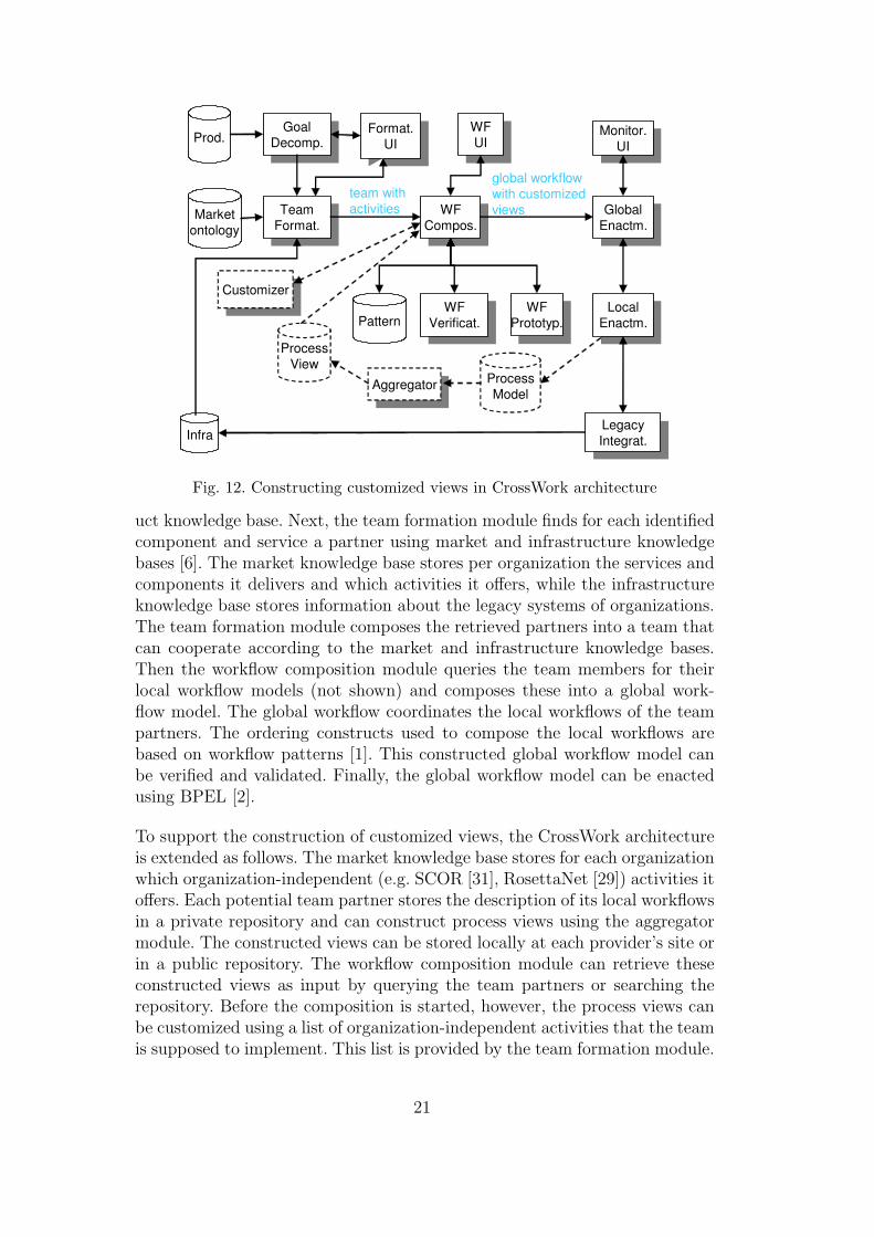
Figure 12 shows the basic CrossWork architecture (solid lines) plus the exten-sion (dashed lines). The basic CrossWork system starts with the activatinggoal decomposition module, which takes an order specification from an OEMand decomposes it into a required set of components and services, using a prod-
20
team with activities
global workflowwith customizedviews
CustomizerCustomizer
AggregatorAggregator
GoalDecomp.
GoalDecomp.
TeamFormat.
TeamFormat.
WFPrototyp.
WFPrototyp.
WFCompos.
WFCompos.
WFVerificat.
WFVerificat.
Monitor.UI
Monitor.UI
Format.UI
Format.UI
Infra
Prod.
Marketontology
Pattern
WFUI
WFUI
GlobalEnactm.
GlobalEnactm.
LegacyIntegrat.
LegacyIntegrat.
LocalEnactm.
LocalEnactm.
ProcessView
ProcessModel
Fig. 12. Constructing customized views in CrossWork architecture
uct knowledge base. Next, the team formation module finds for each identifiedcomponent and service a partner using market and infrastructure knowledgebases [6]. The market knowledge base stores per organization the services andcomponents it delivers and which activities it offers, while the infrastructureknowledge base stores information about the legacy systems of organizations.The team formation module composes the retrieved partners into a team thatcan cooperate according to the market and infrastructure knowledge bases.Then the workflow composition module queries the team members for theirlocal workflow models (not shown) and composes these into a global work-flow model. The global workflow coordinates the local workflows of the teampartners. The ordering constructs used to compose the local workflows arebased on workflow patterns [1]. This constructed global workflow model canbe verified and validated. Finally, the global workflow model can be enactedusing BPEL [2].
To support the construction of customized views, the CrossWork architectureis extended as follows. The market knowledge base stores for each organizationwhich organization-independent (e.g. SCOR [31], RosettaNet [29]) activities itoffers. Each potential team partner stores the description of its local workflowsin a private repository and can construct process views using the aggregatormodule. The constructed views can be stored locally at each provider’s site orin a public repository. The workflow composition module can retrieve theseconstructed views as input by querying the team partners or searching therepository. Before the composition is started, however, the process views canbe customized using a list of organization-independent activities that the teamis supposed to implement. This list is provided by the team formation module.
21

Produce watertank body
Produce pump
Produce motor
Buy motorpump
Produce grommet
Produce cap
Assemble motorpump
Assemblewatertank
Prepare order
Produce motorpump
Deliver watertank
Produce watertank
Fig. 13. Watertank production process
Then, the workflow composition module can compose the customized viewsinto a global workflow. To support the enactment of the local views, alsoextensions are needed but these are outside the scope of this paper.
5.2 Watertank scenario
We now apply the approach to a real-life business scenario from CrossWork [10].A truck manufacturer wishes to outsource production of a watertank compo-nent to a Network of Automotive Excellence, consisting of suppliers. Eachsupplier offers a local workflow as a black-box service to the network. The of-fered services for producing the watertank are composed into a global processusing the workflow composition module [12]. Figure 13 shows the composedglobal process that coordinates the black-box services of the suppliers.
Since the OEM wishes to track progress of the outsourced production process,a customized process view is constructed using the two-step approach. In thefirst step, the NoAE decides that the services for assembly and buying of amotorpump have to be aggregated (indicated with double lines in Figure 13).The output of this step is the non-customized process view shown in Figure 14.In the second step, the truck manufacturer decides that this process view istoo detailed, since it only wishes to monitor the services on the critical path(indicated with double lines in Figure 14). The other services can be omittedin this case. The resulting customized view is shown in Figure 15.
22

Produce watertank body
Produce grommet
Produce cap
Assemblewatertank
Prepare order Deliver watertank
Produce watertank
Produce motorpump
Fig. 14. Non-customized process view of Figure 13
Assemble watertank
Prepare order
Deliver watertank
Produce motorpump
Fig. 15. Customized process view of Figure 14
6 Related Work
The most relevant work related to ours is that by Liu and Shen [21,22]. In [21],they focus on deriving a process view from a given structured process defi-nition. They concentrate too on defining for a structured conceptual processdefinition aggregate activities (virtual in their terminology) from a given setof conceptual-level activities (called essential). However, these activities mustbe basic, so they cannot contain other activities. They define rules on aggre-gates to ensure consistency between an external process view and a conceptualprocess model. They also present an algorithm that derives a minimal virtualactivity from a set of essential activities. Based on this algorithm, from a givenstructured process model, a set of virtual activities can be derived that appearin the process view. The ordering of these virtual activities in the view canbe inferred from the underlying process model. Next, they show that someconsistency requirements between the process view and the original processhold. This work is extended in [22] by considering data flow as well.
This paper improves and extends the work of Liu and Shen [21] in several ways.Basically, their work coincides with our first phase. However, our formaliza-tion of structured process models is much more simple than theirs, leading tomore simple construction rules and a more efficient (linear-time) algorithm aswell. Especially their consistency rules for models containing loops are quitecomplex, and their algorithm has a high complexity (they do not estimate itscomplexity, but due to nested loops the time complexity of their algorithm isat least quadratic in the number of nodes). Next, we support the aggregationof composite nodes, while they only focus on aggregation of activities which
23

have no subactivities. In addition to improving their work, we extend theirwork by allowing views to be customized. Customization involves inheritanceof activities and omission of activities, something which is not considered byLiu and Shen. To simplify the exposition, we have ignored data flow, but itcan be incorporated along similar lines as described in [22].
Chiu et al. [8] use process views to support interoperability of multiple work-flows across organizations. They present a meta model and an interopera-tion model for workflow views, consisting of communication scenarios betweenthese views, and a set of interoperation parameters. Consistency constraintsare described to ensure that a workflow view is consistent with its underlyingworkflow, and that the communication between workflow views, as specified bycommunication scenarios, is consistent. Finally, they show how the approachcan be realized using web services and XML technology. There are several dif-ferences with our work. First, we focus on the actual construction of consistentcustomized process views from a given business process, while they focus onconsistency of a given workflow view and a given workflow. Second, they donot consider customization of views. Third, they consider unstructured processmodels while we focus on structured ones.
Next, there are approaches that use views for enabling inter-organizationalworkflow cooperation [7,35]. The approach of Chebbi et al. [7] consists of threemain steps: workflow advertisement, workflow interconnection, and workflowcooperation. The main focus of the paper is on the second step. They presentreduction rules to derive from an internal process model an abstract processmodel which only contains tasks that cooperate with partner workflows outsidethe organization. On this public process, partner-specific views can be definedthat are linked with an access contract. Zhao et al. [35] use visibility constraintson internal process models to derive partner-specific workflow views. Eachpartner can combine the workflow views of its partner with its internal processinto what Zhao et al. call a relative workflow model. Next, they discuss howan organizational can use a relative workflow model to track the progress ofits indirect partners, e.g. how a consumer can track the progress of the processof the provider of the provider.
There are several differences between [7,35] and our work. First, they donot consider consistency criteria between a public process and internal one,whereas we have formalized these criteria as construction rules. Consequently,they do not give any proof of correctness of their approach. Second, they donot consider customization of views. Third, they consider unstructured processmodels while we focus on structured ones.
Schulz and Orlowska [30] focus on architectural support for workflow (process)views. They look into possible interactions that can occur between workflowviews and between workflow views and private workflows. Next, they ana-
24

lyze how such interactions can be supported by describing different ways ofcoupling workflow views and private workflows. Finally, they define a cross-organizational workflow architecture that supports the execution of workflowviews. Our work complements their work, since we focus on how customizedprocess can be constructed from a given business process, which is not con-sidered in [30]. The customized process views obtained with our approach canbe executed using the technology described by Schulz and Orlowska [30].
This paper builds on earlier research. In the CrossFlow project [14,33], whichdeveloped technology to support the execution of cross-organizational work-flows in dynamic virtual enterprises, already a distinction was made betweenexternal and internal level process models. There, an external level processmodel was specified in a contract, but no support was provided for construct-ing this external process model, i.e., the CrossFlow approach relies on manualconstruction of external process views. In follow-up research, Grefen et al. [15]defined a three-level framework for process outsourcing. In this work, also adistinction between external and internal models is made, but only abstractconstruction rules are presented. This paper complements that work by show-ing how external process views can be automatically constructed from concep-tual process models. Moreover, customization of process views is not addressedin [15]. In a follow-up paper [16], Grefen et al. examined how enactment of(non-customized) process views can be supported using web service technol-ogy. A similar enactment infrastructure can be used to enact customized pro-cess views.
Some existing industrial standards, notably BPEL [2] and BPMN [34], dis-tinguish between an abstract (public) and a concrete (private) process. Theabstract process is a nondeterministic protocol describing possible interac-tions, whereas a concrete process is actually executable by a process engine.This distinction between abstract and concrete process is similar to the onemade in this paper between a process view and its underlying internal process.Unlike our approach, these standards do not define any consistency constraintsbetween these different process levels, nor do they address customization.
On a more general level, there are approaches that tackle the problem of dis-tributed process collaborations by focusing on distributed execution of work-flows [5,26] or process compositions [3]. However, these approaches typicallydo not use different process levels. An exception is Bussler [5], who advocatesthe use of public and private processes, but this work does not provide anyconsistency constraints between them.
25

7 Conclusion
We have presented a two-phase approach for constructing process views fromstructured process models. The main contribution of the approach is that itsupports both providers and consumers. Providers can hide private detailsfrom their internal process models and consumers can remove noise fromprovider process views. The approach is formally defined, which enables anautomated implementation. This allows an efficient way of constructing cus-tomized views. Since we consider structured process models, the approach fitswell with the industrial process standard BPEL [2], which is mainly structured.
As a case study, we have applied the approach to the CrossWork project. Thisshows how the approach can be used in architectures supporting dynamicbusiness-to-business collaborations that are process-oriented rather than function-oriented. In today’s business world, such dynamic cooperations between au-tonomous organizations becomes increasingly important. In the past, organi-zations cooperated with each other in rather static networks. To comply withcurrent market settings, however, organizations have to shift their priority toflexibility and ability to change if they want to survive [27]. As a consequence,dynamic cooperation between organizations is often required to meet marketdemands [13]. Our approach can aid in establishing such dynamic collabora-tions in an efficient way.
There are several directions for further work. First, the approach can be ex-tended to deal with non-structured process models. Another interesting ex-tension is dealing with multilateral views, which span multiple provider andconsumer processes. Such views are especially useful in a choreography set-ting. Finally, the approach can be used to study agent-based negotiation ofviews between consumers and providers. For example, a provider agent mayget a request from a consumer agent to show certain activities from its internalprocess model. The provider agent can compute a process view fulfilling thisrequest, using the approach of this paper, and then decide on whether or netthe offer is profitable enough to accept the process view.
References
[1] W.M.P. van der Aalst, A.H.M. ter Hofstede, B. Kiepuszewski, and A.P. Barros.Workflow patterns. Distributed and Parallel Databases, 14(1):5–51, 2003.
[2] T. Anders, F. Curbera, H. Dholakia, Y. Goland, J. Klein, F. Leymann,D. Roller, D. Smith, S. Thatte, I. Trickovic, and S. Weerawarana. BusinessProcess Execution Language for Web Services, Version 1.1. Standards proposal
26
by BEA Systems, International Business Machines Corporation, MicrosoftCorporation, SAP AG, Siebel Systems, 2002.
[3] B. Benatallah, M. Dumas, and Q.Z. Sheng. Facilitating the rapid developmentand scalable orchestration of composite web services. Distributed and ParallelDatabases, 17(1):5–37, 2005.
[4] D. Bianchini, V. De Antonellis, B. Pernici, and P. Plebani. Ontology-basedmethodology for e-service discovery. Information Systems, 31(4):361–380, 2006.
[5] C. Bussler. The application of workflow technology in semantic B2B integration.Distributed and Parallel Databases, 12(2/3):163–191, 2002.
[6] M. Carpenter, N. Mehandjiev, and I.D. Stalker. Flexible behaviours foremergent process interoperability. In S. Reddy, editor, Proc. WETICE 2006,pages 249–255. IEEE Computer Society, 2006.
[7] I. Chebbi, S. Dustdar, and S. Tata. The view-based approach to dynamic inter-organizational workflow cooperation. Data Knowl. Eng., 56(2):139–173, 2006.
[8] D.K.W. Chiu, S.C. Cheung, S. Till, K. Karlapalem, Q. Li, and E. Kafeza.Workflow view driven cross-organizational interoperability in a web serviceenvironment. Inf. Tech. and Management, 5(3-4):221–250, 2004.
[9] CrossWork consortium. Crosswork project, IST no. 507590.http://www.crosswork.info.
[10] CrossWork consortium. MAN use case summary and mapping, 2006.
[11] CrossFlow. Final Report (D16). Available at http://www.crossflow.org.
[12] R. Eshuis, P. Grefen, and S. Till. Structured service composition. In S. Dustdar,J.L. Fiadeiro, and A. Sheth, editors, Proc. of the 4th International Conferenceon Business Process Management (BPM 2006), volume 4102 of Lecture Notesin Computer Science, pages 97–112. Springer, 2006.
[13] P. Grefen. Towards dynamic interorganizational business process management(keynote talk). In S. Reddy, editor, Proc. WETICE 2006, pages 13–18. IEEEComputer Society, 2006.
[14] P. Grefen, K. Aberer, Y. Hoffner, and H. Ludwig. CrossFlow: Cross-organizational Workflow Management in Dynamic Virtual Enterprises.International Journal of Computer Systems, Science, and Engineering,15(5):277–290, 2001.
[15] P. Grefen, H. Ludwig, and S. Angelov. A three-level framework for process anddata management of complex e-services. International Journal of CooperativeInformation Systems, 12(4):487–531, 2003.
[16] P. Grefen, H. Ludwig, A. Dan, and S. Angelov. An analysis of web servicessupport for dynamic business process outsourcing. Information and SoftwareTechnology, 48(11):1115–1134, 2006.
27
[17] P. Grefen, N. Mehandjiev, G. Kouvas, G. Weichhart, and R. Eshuis. Dynamicbusiness network process management in instant virtual enterprises. BetaWorking Paper Series, WP 198, 2007.
[18] D. Harel, A. Pnueli, J. P. Schmidt, and S. Sherman. On the formal semanticsof statecharts. In Proceedings of the Second IEEE Symposium on Logic inComputation, pages 54–64. IEEE, 1987.
[19] D. Harel and R.E. Tarjan. Fast algorithms for finding nearest commonancestors. SIAM Journal on Computing, 13(2):338–355, 1984.
[20] B. Kiepuszewski, A.H.M. ter Hofstede, and C. Bussler. On structured workflowmodelling. In B. Wangler and L. Bergman, editors, Proc. CAiSE ’00, pages431–445. Springer, 2000.
[21] D.-R. Liu and M. Shen. Workflow modeling for virtual processes: an order-preserving process-view approach. Inf. Syst, 28(6):505–532, 2003.
[22] D.-R. Liu and M. Shen. Business-to-business workflow interoperation based onprocess-views. Decision Support Systems, 38(3):399–419, 2004.
[23] R. Liu and A. Kumar. An analysis and taxonomy of unstructured workflows.In W.M.P. van der Aalst, B. Benatallah, F. Casati, and F. Curbera, editors,Proc. 3rd Conference on Business Process Management (BPM 2005), LectureNotes in Computer Science 3649, pages 268–284, 2005.
[24] D. Martin (editor), M. Burstein, J. Hobbs, O. Lassila, D. McDermott,S. McIlraith, S. Narayanan, M. Paolucci, B. Parsia, T. Payne, E. Sirin,N. Srinivasan, and K. Sycara. Owl-s: Semantic markup for web services, 2004.http://www.daml.org/services/owl-s/1.1/ overview.
[25] R. Milner. Communication and Concurrency. Prentice Hall, 1989.
[26] P. Muth, D. Wodtke, J. Weißenfels, A. Kotz Dittrich, and G. Weikum. Fromcentralized workflow specification to distributed workflow execution. Journalof Intelligent Information Systems, 10(2):159–184, 1998.
[27] R. Pieper, V. Kouwenhoven, and S. Hamminga. Beyond the hype: E-businessstrategy in leading European companies. Van Haren Publising, 2002.
[28] A. Pnueli and M. Shalev. What is in a step: On the semantics of statecharts.In T. Ito and A.R. Meyer, editors, Theoretical Aspects of Computer Software,Lecture Notes in Computer Science 526, pages 244–265. Springer, 1991.
[29] RosettaNet consortium. RosettaNet. http://www.rosettanet.org.
[30] K.A. Schulz and M.E. Orlowska. Facilitating cross-organisational workflowswith a workflow view approach. Data Knowl. Eng., 51(1):109–147, 2004.
[31] Supply Chain Council. Supply chain operations reference model (SCOR).http://www.supply-chain.org, 2006.
28

[32] UML Revision Taskforce. UML 2.0 Superstructure Specification. ObjectManagement Group, 2003. OMG Document Number ptc/03-07-06. Availableat http://www.uml.org.
[33] J. Vonk and P.W.P.J. Grefen. Cross-organizational transaction support fore-services in virtual enterprises. Distributed and Parallel Databases, 14(2):137–172, 2003.
[34] S.A. White et al. Business Process Modeling Notation (BPMN) Specification,Version 1.0. Object Management Group, 2006. http://www.bpmn.org.
[35] X. Zhao, C. Liu, and Y. Yang. An organisational perspective on collaborativebusiness processes. In W.M.P. van der Aalst, B. Benatallah, F. Casati, andF. Curbera, editors, Proc. 3rd Conference on Business Process Management(BPM 2005), Lecture Notes in Computer Science 3649, pages 17–31, 2005.
Appendix
Proof of Theorem 1. Denote by agg the set returned by Aggregate(P,X).We prove the claim in two steps: first we show that agg complies with theconstruction rules (i), and next we show that agg is minimal (ii).
i. We only show the proof for Rule 2; the proofs for the other rules are bysimilar reasoning.
Let x, y ∈ agg such that there is a z ∈ N with x < z < y. We will show thatz ∈ agg.
Since x < z < y, we have lx,y,z = lca({x, y, z}) is of type SEQ. If lx,y,z = l, byl. 11 of Aggregate, we have z ∈ agg. If lx,y,z is a strict descendant of l, solx,y,z 6= l, there are two cases:
• l is of type PAR or XOR. Let c be the child of l that is ancestor of lx,y,z.Then c ∈ C and so z ∈ agg by l. 13.
• l is of type SEQ. Let cz be the child of l such that z is descendant of cz.Since x < z < y, cz ∈ C ∪ C ′. The claim then follows from l. 11.
ii. We prove the claim by contradiction. Suppose there is another set agg ′, withagg′ ⊂ agg, such that X ⊆ agg′ and agg′ does not violate the constructionrules 2, 3, and 4.
Let n be a node in agg \ agg′, so n is superfluously added to agg by thealgorithm. We now examine the cases where n might have been added to agg
by the algorithm:
• l. 4. Since l ∈ X, by assumption l ∈ agg′. Let n′ be the node in agg \ agg′
29

such that n′ is descendant of l and n′ is ancestor of n and parent(n′) ∈ agg′.Since n′ 6∈ agg′, Rule 3 is violated for agg′.
• l. 11. Then the lca of X is of type SEQ. Then n is a descendant of eithersome child c′ ∈ C ′ (l. 10) or of some child c ∈ C (l. 7). In the first case,n 6∈ agg′ violates Rule 2. In the second case, there is a node x ∈ X suchthat x is descendant of c (l. 6). Since n ∈ agg \ agg′, n 6= x. There are threesubcases now· n is strict descendant of x. Let n′ be the node in agg \ agg′ such that n′
is a strict descendant of x and ancestor of n and parent(n′) ∈ agg′. Sincen′ 6∈ agg′, Rule 3 is violated.
· n is strict ancestor of x. Let n′ be the node in agg \ agg′ such that n′ isdescendant of n and a strict ancestor of x and children(n′) ∩ agg′ 6= ∅.Since n′ 6∈ agg′, Rule 4 is violated.
· n < x or n < x or n⊥x. Let ln,x = lca({n, x}). Since ln,x is a strict ancestorof x but a descendant of c, node ln,x is in agg′ by the previous case. Let n′
be the node in agg \ agg′ such that n′ is a (strict) descendant of ln,x andparent(n′) ∈ agg′. Since n′ 6∈ agg′, Rule 3 is violated.
• l. 13. Let x ∈ X be a node such that x ∈ aggC. By assumption (Rule 1),x ∈ agg′. So n 6= x. Let cx be the child of l that is ancestor of x.· n is strict descendant of x. Let n′ ∈ agg \ agg′ be a descendant of x that
is ancestor of n such that parent(n′) ∈ agg′. Since n′ 6∈ agg′, then agg′
violates Rule 3.· n is strict ancestor of x. Let n′ ∈ agg \ agg′ be a descendant of n that is
ancestor of x such that children(n′)∩ agg′ 6= ∅. Since n′ 6∈ agg′, then agg′
violates Rule 4.· n⊥x. Let ln,x = lca({n, x}). Since ln,x is strict ancestor of x, by the pre-
vious case ln,x ∈ agg′. Let n′ ∈ agg \ agg′ be a descendant of ln,x thatis ancestor of n such that parent(n′) ∈ agg′. Since n′ 6∈ agg′, then agg′
violates Rule 3.
Thus, in each case agg′ violates a construction rule, which contradicts theassumption. �
30