Embed Size (px)
Citation preview
Consortium for Electric Reliability Technology Solutions
White Paper on
Protection Issues of
The MicroGrid Concept
Prepared for
Transmission Reliability Program Office of Power Technologies
Assistant Secretary for Energy Efficiency and Renewable Energy U.S. Department of Energy
Prepared by
William E. Feero, Consultant, Reedsville, PA Douglas C. Dawson, Consultant, North Hollywood, CA
John Stevens, Sandia National Laboratories, Albuquerque, NM
March, 2002
The work described in this report was coordinated by the Consortium for Electric Reliability Technology Solutions, and funded by the Assistant Secretary of Energy Efficiency and Renewable Energy, Office of Power Technologies of the U.S. Department of Energy under Contract No. DE-AC03-76SF00098

MICROGRID PROTECTION ISSUES
Introduction and Summary
This report examines the protection problems that must be dealt with to successfully operate a microgrid when the utility is experiencing abnormal conditions. There are two distinct sets of problems to solve. The first is how to determine when an islanded microgrid should be formed in the face of the array of abnormal conditions that the utility can experience. The second is how to provide segments of the microgrid with sufficient coordinated fault protection while operating as an island separate from the utility.
As used in this discussion, the term microgrid refers to conventional distribution systemswith distributed resources (DR) added. This is not to imply that the simple addition of DR to a distribution system creates a microgrid. In a microgrid the DR(s) has sufficient capacity to carry all, or most, of the load connected to that portion of the distribution system that houses the DR. In addition, a microgrid can operate as an electrical island in times of disturbance to the main utility system. Thus, there will be a well-definedinterconnection point where the microgrid can be disconnected from the bulk of the electric utility system if so desired. Figure 1 is an example of what a microgrid’snetwork might look like.
Shedable loads
Power/Heat Coordinator Power Flow Controller Circuit Breaker Heat Load
Protection Coordinator Communication Fast protection
Shedable loads
Power/Heat Coordinator Power Flow Controller Circuit Breaker Heat Load
Protection Coordinator Communication Fast protection
Figure 1 Typical Microgrid
2

The discussion in this report generally presumes that basic elements of microgrids (such as fuses, circuit breakers and over-current detection devices) will perform in a mannerconsistent with those present in existing distribution systems. An element that is not well defined is the inverter interface with the power system. There is a concern that, not only will each inverter design have different constants, but that the basic characteristics of the unit presented to the system can change markedly depending on the design goals of a particular manufacturer and/or application. It seems certain that the inverter fault current capability will be less than twice the rated current of the inverter unless the unit is specifically designed to provide high fault current. This is a marked departure from the relatively high fault-current capability typical of synchronous generation capability. If a significant portion of the microgrid’s generation has inverter interfaces, the change fromutility-connected operation to islanded microgrid operation may aggravate a concern for using current-based fault detection.
The protection systems must respond based on a pre-set understanding of the boundary between normal and abnormal conditions. Many protection issues associated with microgrids will not be truly resolved until the millisecond-by-millisecond dynamics prior to, during, and following microgrid separation from the utility are well understood. In fact, during an impromptu meeting on this subject with approximately 30 utility protective relay engineers, the salient need they expressed was the ability to simulate the expected response of the microgrid when separating from the utility and in disconnected microgrid operation. Therefore the findings of this report are general observations based on the present understanding of expected microgrid dynamic response characteristics.
3

Making the decision of when to separate from the utility first requires a realistic expectation of what benefit the microgrid will gain from rapid separation. Whileequipment standards such as SEMI F47 suggest that many manufacturers would benefit from separation times of less than 50 milliseconds after an abnormal condition is started on the utility, such times are not possible with presently available protective devices (as noted in footnote 1, below). If very high speed separation is required and nuisance trips are to be avoided (see the Nuisance Separation section below for a discussion of whether nuisance separations should be tolerated in a trade for improved reliability), then transfer trip systems must be installed between the utility substation and the breaker at point ofcommon coupling (PCC) with the microgrid. (Note that the PCC is the point where the Main Microgrid Separation Device is shown on figure 1.) Separating for non-fault conditions will also benefit from having high-speed communication channels between the utility and the microgrid.
When the microgrid has separated from the utility, a host of new issues must be accommodated. A means to assure appropriate grounding must be provided. The equipment used for detection of faults internal to the microgrid must work with, or around, the protection that exists for fault detection while connected to the utility. A means of detecting faults that is not dependent on a large ratio between fault current and maximum load current must be provided. Any existing anti-islanding schemes will have to be examined, and perhaps modified, to prevent instability or loss of DR units with sensitive settings. Any load shedding schemes set up by the utility in the microgrid area will have to be closely coordinated.
The following sections explore these areas to determine what might be done with present protective devices to resolve these issues. Modern protection techniques are highly evolved from nearly a century of experience. Thus caution should be used in any attemptsto revolutionize approaches to system protection.
Grid Separation
In a preliminary evaluation for this report, the following issues were listed forconsideration:
Protection operation speed required to approach SEMI F47 specifications1
Nuisance separations: how to minimizeIs non-fault separation (for low voltage, open phase, voltage imbalance, etc.) desirable?Separation protection limitations imposed by microgrids that export power to the utility
1 Note that it is not possible, at least with electromechanical switching devices, to meet the SEMI F47 specification for all fault types and locations. The SEMI specification does not permit voltages below50%, even with durations as short as 0.05 sec. (3 cycles at 60 Hz.) If a utility feeder fault causes thevoltage to drop below 50%, there is nothing that can be done except to separate as quickly as possible (see Figure 2).
4
Re-synchronization to utility: enable automatically or manually, match frequency and voltage automatically or manually?
Implicit in this list is the acceptance of many concurrent factors. Microgrid means very small power capacity relative to the utility, e.g., less than 10 MVA. Any system that is designated as a microgrid will have sufficient generation sources to carry a significantportion of the microgrid’s load. As such, under improper separation from the utility, i.e., not at the PCC, it will have the possibility of carrying part of the utility. IEEE standards activity will soon be setting minimum interconnection protection criteria, which any microgrid may have to meet while operating interconnected. Economics is important.Finally, the reality that even excellent protection packages cannot compensate for all of the special needs to operate a microgrid must be recognized.
Rapid Separation from a Faulted Feeder
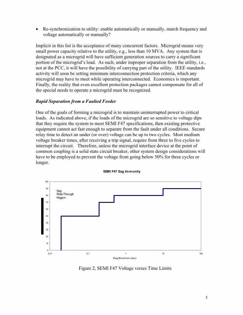
One of the goals of forming a microgrid is to maintain uninterrupted power to critical loads. As indicated above, if the loads of the microgrid are so sensitive to voltage dips that they require the system to meet SEMI F47 specifications, then existing protective equipment cannot act fast enough to separate from the fault under all conditions. Secure relay time to detect an under (or over) voltage can be up to two cycles. Most mediumvoltage breaker times, after receiving a trip signal, require from three to five cycles to interrupt the circuit. Therefore, unless the microgrid interface device at the point of common coupling is a solid state circuit breaker, other system design considerations will have to be employed to prevent the voltage from going below 50% for three cycles or longer.
SEMI F47 Sag Immunity
0
10
20
30
40
50
60
70
80
90
100
0.01 0.1 1 10 100
S a g Dur a t i on ( se c )
SagRide-ThroughRegion
Figure 2, SEMI F47 Voltage verses Time Limits
5

To combine design and protection improvements, first let’s look at the case where separation is not required, i.e., the fault is not located between the PCC and the substation breaker. For example, a fault causing a sag on a substation bus may be on an adjacent feeder fed from the same substation. An example of design considerations could be to install electronic sag correctors that have recently become available. Or, if the transformer at the point of common coupling is the widely used wye-wye connection, replacing it with delta-wye transformer and adding a high side breaker may be another option. (For single-line-to-ground, SLG, faults in the utility, this transformer connection will ensure that the phase-to-ground voltage in the microgrid does not drop below 58%).These two possible options are useful to demonstrate how protection considerations and design options must be considered together in evolving economic microgrids.
Electronic sag protectors are available that do not use energy storage. These devices are typically effective for only a couple of cycles. For longer protection periods, extending into the realm of many minutes, electronic sag protectors that incorporate an energy storage device, such as a battery, are necessary. Microgrid owner/operators might be reluctant to pay the increase in cost to install electronic sag protectors that utilize any significant amount of energy storage. However, emerging devices do not require significant storage if the under voltage does not last too long or is not less than 50%. For abnormal conditions that cause zero voltage, most electronic sag protectors can hold up the voltage for three cycles. If instantaneous relays and three cycle breakers are applied to all feeders adjacent to the one supplying the microgrid, then, at least for adjacent feeder faults, the combination of electronic sag correctors and high speed relaying maymeet the SEMI F47 requirements. Of course, the issue of faults within the microgrid still remains. The solution will depend on utility practices such as fuse saving. If modernpower quality requirements govern the utility protection practice, they will be using quick blow fuses in which case the electronic sag correctors should still make it possible to meet SEMI F47. If the utility uses instantaneous overcurrent tripping of the feeder (for fuse saving purposes), then separation of the microgrid will be required.
Using a delta-wye interconnecting transformer may be a low cost, albeit less effective solution. Since SEMI F47 only allows the voltage to be depressed below 70% for 0.2 seconds, the utility protective action must still be rapid. Also the delta-wye interconnection is only effective for single-line-to-ground faults on the delta side and loads connected line-to-neutral on the wye side.
Now consider the case where the fault is on the feeder between the microgrid and the substation (that is, “upstream” of the Main Microgrid Separation Device indicated on figure 1). For this case the microgrid must separate from the utility. Emerging standard requirements, utility protection requirements, and any hope of meeting SEMI F47 requirements all converge on the need to separate rapidly. For this condition, there is no maintaining even a low under voltage tie to the utility. The present speed limitations of the protective devices now become insurmountable without electronic sag correctors with storage if SEMI F47 is the target criteria. The amount of storage contained in the electronic sag corrector can be kept reasonably small if high speed tripping is employed.This presumes the microgrid has adequate controls to rapidly recover the voltage and maintain near system frequency when islanded by clearing a tie line fault.
6

Nuisance Separations
The above discussion should have made it obvious that maintaining the tie between the utility and the microgrid is highly desirable except when the fault is on the tie between the substation and the microgrid. It also should be obvious that when separation is required it should be rapid as possible. Unfortunately inexpensive protective schemes are not secure, that is, they are prone to false trips. The emerging standards specify mandatory voltage and frequency trip settings for measurements made at the PCC.However, voltage and frequency are poor discriminators for determining if the fault is on the feeder to the microgrid, or within the microgrid itself. Currently the only reliable and secure means for rapidly tripping the microgrid breaker is a transfer trip from the substation breaker.
This security from false or nuisance trips is not just an electromechanical relay and breaker problem. Even the most sophisticated microprocessor package acting solely on information available at the PCC cannot always determine the fault location given the extreme difference in energy capability between the utility and the microgrid.
The difference between a distributed resource and a microgrid is most clear when considering the importance of nuisance trips. For a simple DR interconnection, the cost of a nuisance trip is normally just the lost kWh sales for a brief period and the cost of restart and re-synchronizing. For a microgrid, a nuisance trip is significant exposure to unacceptable power quality problems. Therefore the cost of interconnection protection should be examined as insurance against potential manufacturing production lost, not merely kWhrs lost.
However, if the microgrid has been designed as a valid backup source of power for the loads of the microgrid or a “power park,” then nuisance separations are not all that serious and can be tolerated as preferable to remaining connected to a utility feeder that is undergoing a disturbance and may experience an outage. Separating from the utility removes the disturbance from the microgrid system and allows it to continue operating unmolested. A nuisance separation has little impact on either the microgrid or the utility as long as the microgrid has been adequately designed. The big advantage of tolerating nuisance tripping is that the relaying threshold conditions for separation can be defined by voltage and frequency deviations and time durations, without regard to whether these are good indicators of the location of a utility system fault. That is, if the voltage is out of range for a time exceeding the allowable, separation should occur, regardless of whether the underlying disturbance will ultimately result in an outage to the utility feeder. This is a simpler relaying problem than trying to estimate, from voltage and current measurements at the PCC, whether the utility fault is between the utility substation and the PCC, or elsewhere.
Microgrid designs that might argue against such an approach are:
Microgrids which are intended to shed non-critical load upon separation. (That is, the DR capacity within the microgrid cannot dependably support the loads of the
7

microgrid.) In such cases, the outages to non-critical loads might become a real nuisance.
Microgrids which export power to the utility under normal operating conditions. In these conditions, nuisance separations would entail a loss of revenue and a period of overfrequency operation while the frequency on the microgrid stabilizes. Also, the utility might feel that such frequently interrupted generation was not worth as muchas generation not so subject to interruptions.
Non-fault Separation
Low voltages can exist for non-fault conditions. The determination of whether a low-voltage condition is an indication of a fault in the system between the PCC and the substation can be difficult without high-speed communication between the PCC and the substation. In general, the utility and the microgrid would benefit from remainingconnected while the utility works to resolve the cause of the low voltage if it is not the result of a fault that requires tripping at the PCC. It might be desirable for the microgridand the utility to negotiate a trip control to coordinate with the SEMI F47 voltage limitsfor balanced voltage conditions. Such control could either be achieved by communication with the utility or by balanced voltage blocking of single phase under-voltage relays at the PCC when the desired voltage trip levels are lower than the delayed trip settings that may be required by other standards such as are being developed within the IEEE P1547 project. However, since the levels being considered in P1547 are set to determine an unintended island condition, there may not be a conflict because P1547 as presently written does not cover “intentional islanding”.
Relaying systems could be designed from presently available devices to provide the above trip restraint for balanced under voltage conditions. The larger question is can the microgrid recover from operation at such depressed voltage levels if tripping is eventually required? These microgrid operational restraints are more likely to determinethe under-voltage trip point.
Voltage unbalance normally exists to some degree on most distribution feeders under normal operating conditions. The desirability for the microgrid to separate at some level of voltage unbalance will be a function of such factors as the transformer connections and grounding points within the microgrid. The distribution apparatus, distributed generation and loads being served all need to be considered for their sensitivity to voltage unbalance to determine the criteria for establishing the microgrid design. For voltage unbalance conditions, the protective function dilemma is how to determine whether the cause for the unbalance is internal to the microgrid or external to it. Such a determination may be complicated by the ratio of the power supplied internal to the microgrid to the load demand internal to the microgrid. Some form of intelligent controller at the PCC could be needed to make the appropriate decision to separate or not based on voltage unbalance.
8

Open phase occurrences are generally associated with systems where fuses are located between the substation and the PCC. While non-fault initiated open phases are rare, they do occur. Detection of the event is complicated, depending on the number and type of transformers between the open phase and the PCC where a three-phase switching device must exist. Since an open phase will permit phase-to-phase voltages to remain at or above 50%, it might be tempting for the microgrid not to want to separate for this condition. However, in general an open phase condition must be considered a hazard to transformers and the DR generators in that, under many conditions, excessive over currents or over voltages can exist if not isolated with three-phase switching. Also, if the maintenance work is not done live-line, then hazardous work conditions may be created for utility line workers. Therefore, allowing a microgrid to be constructed where fusesexist between the PCC and the substation circuit breaker should be discouraged. If one is set up it must provide a means for separating because of an open phase condition.
Separation from Exporting Microgrids
Obviously microgrids that routinely export power cannot use simple means such as reverse power relays to determine abnormal conditions in the utility. Less obvious is that simple over and under voltage relays may not be reliable in ensuring tripping for utility faults when the microgrid has adequate generation capacity to export energy. Since the exporting microgrid contains generation in excess of the microgrid maximum load, then the utility to microgrid impedance ratios will be closer to each other than they are in a non-exporting microgrid. Under such conditions, the division of voltages in a microgridduring a fault may be markedly different from that which exists when an importingmicrogrid is connected to the utility.
While most utilities would want to proceed with extreme care for setting up any form of microgrid on a secondary or spot network, an exporting microgrid will require a majorredesign of the protection and control of the network protectors and relay systems fromconventional practice. Network protector manufacturers are moving to develop the equipment required to make such changes technically feasible.
Re-synchronizing
Relaying and controls exist for manually or automatically re-synchronizing a synchronous generator and automatically re-synchronizing an inverter interfaced DR. If the microgrid contains only a single generator, the decision to use either manual or automatic means will be largely dependent on availability and skill level of a microgridoperator. However, if the microgrid consists of multiple DRs at various locations in the microgrid, then automatic re-synchronizing means should be integral to the microgriddesign. This would be another use for some form of a master controller located at the PCC. (Such a controller could have other refinements such as delayed re-synchronizing during storm conditions where disturbances may be frequent). It will also necessitate communications with at least the major generators in the microgrid.
9
Isolated Microgrid Protection Issues
Once a disturbance has caused the microgrid to separate from the main utility and operate as an island, a different set of considerations become important. In the preliminaryevaluation mentioned earlier in this report, four protection considerations are listed: microgrid distribution system fault protection, microgrid generation protection, NEC issues, and neutral grounding requirements. These considerations for the isolated microgrid are discussed below. In these discussions, it is assumed that a “proper” separation has occurred, specifically the separation occurred at the PCC.
Microgrid Distribution System Protection
The issues identified are:
For faults on the “bulk power” (medium voltage, or MV) portion of the microgrid,it’s probably relatively easy (cheap) just to trip all the microgrid generation. Should this be considered acceptable, since an MV fault while operating isolated is a second contingency? Or is it necessary to selectively isolate faults on the MV system and keep the remainder of the microgrid operating and the various microgrid customerstied together?LV main over current and LV feeder protection: what levels of fault current versus load are needed for these to function as intended? What is the protection impact of having dispersed generation resources on the microgrid versus having a central microgrid generation facility?
Microgrid “Bulk Power” Protection
The postulate of a fault on an MV system needs to be carefully examined. First, it is assumed that MV means any voltage between 2.4 kV and 34.5 kV. Any system that encompassed an HV system, usually thought of as voltage levels from 69 kV to 230 kV, would be a mini grid (such systems were designed as separation contingencies for southern Florida before their transmission ties to the north were strengthened). Second, it is not clear that protection at the DRs would always provide timely clearing of MV faults.
Let us consider the second contingency philosophy as mentioned in the first bullet. The fault discussed here is considered “second contingency” because the first contingency has already happened. That is, something happened that resulted in an isolated microgrid.Thus, a fault on this isolated microgrid is a second occurrence, or second contingency.
If we consider that the microgrid is confined to a typical on-site distribution system, then the only MV protective devices are likely to be the distribution transformer fuses on the MV/LV transformers. These fuses are typically sized to operate rapidly (0.1 - 0.2 seconds) for the available fault current from the utility, which may be 20 - 50 times the maximum load current carried by the fuse. The fuses are intended to have time-delayedoperation (0.5 - 1.5 seconds) for the fault current seen by the fuse for a fault on the LV side of the transformer (typically 10 - 20 times the maximum load current).
10
When operating such a system as an isolated microgrid, the available fault current fromthe microgrid resources for a fault on the MV system will likely not exceed 5 times the full load current and may be considerably less. Given their extremely inverse time-current characteristics (figure 3 illustrates a typical inverse time-current characteristic), the fuses will be extremely slow for such faults, and probably impossible to coordinate with protection of the microgrid DR units.
Faced with this situation, the protection engineer has two choices: (1) give up and accept the fact that a fault on the microgrid MV system will result in a microgrid outage or (2) add protective devices to the MV system that can be coordinated with the DR protection.If the existing MV protection is only fuses, choice (2) entails adding MV circuit breakers (CBs) as well as protective relays, an expensive proposition. Choice one (1) is called“accepting misoperation for a second contingency,” in that, if the microgrid was already isolated from the utility, then a subsequent fault on the microgrid MV system would be a second contingency which is considered tolerable when weighed against the expense of adding MV CB’s and protective relays.
However, even a simple “on-site” microgrid can experience complexities. The first faultmay be on the transformer side of a MV fuse. (This is relatively common, and is typically the result of wildlife, such as a snake, crawling across the top of a transformerand shorting across the high-voltage bushing, creating a path for electricity to flow fromthe high-voltage terminal to the grounded transformer case.) In this case, with the microgrid still connected to the utility, the fuse will likely blow rapidly because of the high utility fault current contribution. This could leave the microgrid with an un-cleared fault or an open phase condition. If the microgrid has been previously separated, there may not be enough fault current to blow the fuse.
The first fault may be on the “main line” of the microgrid MV system. In this case, the microgrid must separate from the utility, to remove the fault from the utility system. Ifthe microgrid were separated earlier from some other disturbance and this fault was a second contingency, the result is the same. Choice (1) and (2) above are still applicable.However, for a microgrid with generation distributed around the microgrid there is also a third choice: (3) arrange relaying at suitable points in the LV system so that the distributed generators can isolate from the MV system and continue to operate, supplying their local loads.
For multi-site DRs in a microgrid that spans more than one on-site location as is illustrated in figure 1, choice (2) or (3) seem to be desirable. In order for the separation relaying at the PCC (almost certainly to be located in the MV system) to have time to separate the microgrid from the remainder of the utility system, the protection at the DRs would be time delayed for faults within the microgrid. Assuming that grounding in the microgrid were adequate to prevent damaging over voltages, such time delays might be acceptable since the fault currents will be considerably less than those that would exist in a utility-connected system. However, will DRs embedded in a microgrid be required to back up the protection at the PCC? As noted earlier it is not clear that the DR protection package for a DR buried in a microgrid will be required to have any system fault
11
detection relaying. However, it is unlikely that any DR can be operated for a long period of time with essentially a short circuit on its terminals. Thus some form of back-up protection, perhaps included in the DR package from the manufacturer, may exist regardless of standards requirements.
If the microgrid system is complex and a master controller at the PCC is used, it might be most efficient for the DRs to only contain protection to prevent damage to themselves. In such a system it would seem that line or circuit segment protection would be desired. It might be possible to achieve coordinated protection of the various circuit segments by the relatively simple means of directional over-current devices. However, two conditions that are required to make these relay systems work cannot be counted on to be present: fault current magnitudes that are location sensitive and fault currents that are much larger than load currents. Further, many of these directional devices would have to automatically adapt from fault-current levels available while utility connected to fault-current levels available after separation from the utility. Any system that relies on zero sequence current-voltage product relays may find coordination of product relays is an issue. The relatively high impedances of the microgrid source may result in the operation times of the two relays moving closer together. Selectivity can be achieved by utilizing some form of differential protection around each circuit segment. Microgrid continued operation may require communication with the devices that trip any faulted circuit segment.
Low Voltage Fault Clearing Requirements
Existing power system protective devices are designed and applied for the fault conditions which normally prevail on a power system: maximum fault current levels of two to 20 or more times the maximum load to be served.
Power system over-current protection devices are time-current coordinated with one another so that the device closest to the fault location operates first. Other upstreamover-current protection devices may also detect the presence of the fault, but are adjusted to be slower than the primary device at the maximum fault current which can flow through both protective devices. In such coordination, as illustrated in Figure 3, advantage is taken of the natural falling off of fault current as the fault is moved away from the source. The impedance of lines and transformers, which adds up as the fault is moved farther from what is typically considered an infinite bus, causes this effect. In distribution systems, both MV and LV, inverse-time over-current and high-set instantaneous over-current functions are used, which makes fault clearing time roughly proportional to distance from the substation.
12

Figure 3, Time-current coordination of protection devices.(Note that for a given fault current, say 900 amps, device 3 will open first, then
device 2, with device 1 opening last.)
The microgrid is not likely to appear as an infinite bus on the MV side of the LV transformer. In fact the apparent impedance of the microgrid source may be much higher than that of the transformer. Therefore the current may change by relatively smallamounts as the fault moves further into the LV system. In an over-current coordinated system as shown above, the change from utility connected to an isolated microgrid has the potential to slow fault clearing and quite likely limit backup protection. Whether the effect is significant depends on a number of variables:
The time-impedance characteristics of the microgrid sources, i.e., do they exhibit sub-transient, transient, or synchronous time effects. The pickup setting of the instantaneous over-current device in relation to the maximum fault current available from the microgrid.The degree of “inverse ness” of the time-over-current characteristic in the region of currents provided by the microgrid, i.e., how much the time delay changes for a change in the fault current. Whether the over-current protection settings can be readjusted to account for the change from utility-interconnected to islanded microgrid or must accommodateconditions for both utility connection and microgrid-only connection with one setting.
13

Some general observations can be made:
Coordination between two protective devices is unlikely to be disturbed by the change to a microgrid-only source since the devices are coordinated at the maximum fault current which can flow simultaneously through the primary and backup device. At lesser levels of current, the coordination margin usually improves.If fault currents at levels of more than 10 times the pickup of the time-over-current functions are available, the change will not have much effect on the timing of these functions because the time-current curves are relatively “flat” (not so inverse) at these current levels. Fuses and time-over-current functions with extremely inverse characteristics have a more pronounced change in timing even at currents of 10-20 times pickup (which seems highly unlikely in microgrid operation.)The biggest change to fault clearing times is likely to come from microgrids that drop the fault current below the setting of an instantaneous over-current function. Faults that were previously cleared in a few cycles might now require a significant portion of a second to be cleared.
It is interesting to note that, if a fault-current-limiting circuit breaker were employed at the PCC, fault levels in the MV and LV systems could be held relatively close in either interconnected or microgrid operation. Such a system may require a fundamental change in the philosophy of fault current protection, but it might make the switch frominterconnected to microgrid operation more seamless.
DRs Dispersed in the Microgrid
Unless the generation of the microgrid is located at the PCC bus, the changes in fault protection will need to accommodate more than just a significant reduction in available short circuit currents. If the DRs are dispersed throughout the microgrid, then the microgrid takes the form of a quasi-network. While there are not likely to be parallel feeds to supply loads after an internal fault, fault current may flow in either direction on many of the distribution feeders. For faults between a satellite DR and the controlling DR(s), it will be necessary for the satellite DR to remove itself from the system in the same manner as being considered in P1547. This requirement may be difficult to meet if the DR protection were designed to not trip for faults on the utility side of the PCC.High-speed communication between the master controller and all the circuit breakers of the microgrid may be the only reliable means to gain such selective tripping.
Microgrid Generation Protection
Issues raised on this subject are:
How best to widen voltage and frequency protection tolerances when operating isolated?How best to disable anti-islanding protection when operating isolated?
14
Is there a need for anti-islanding protection for dispersed generators within a microgrid?Will existing inverter active anti-islanding techniques lead to voltage or frequencyinstability if used in a microgrid?Does a microgrid need underfrequency load shedding for its own reliability? How to coordinate with utility UF load shedding?
Most of these issues can only be addressed by dynamic simulation studies since we have very little experience to draw upon.
Changing Voltage and Frequency Windows
Widening the voltage and frequency windows during islanded microgrid operation seems, intuitively, to be desirable, but is it? The windows were set originally as protection boundaries. If connected equipment damage were the basis for setting these windows, then it would seem they should not be changed. If they were set as fault and island detection levels, then maybe they can be changed, but not without specific study, or, under the control of a microgrid master controller.
Anti-islanding
Should the anti-islanding controls on inverter interfaces be disabled on DRs in a microgrid? This question can only be answered by simulation studies for any given system. In general, it would seem that such controls would have to be deactivated for proposed microgrids unless the ratio of conventional synchronous generation to inverter interfaced generation is very large. However, this may leave the microgrid exposed to uncontrolled islands.
Since many of the anti-islanding controls can act very rapidly to cause tripping, it may be necessary to have the anti-islanding devices deactivated instantly on the detection of forming an isolated microgrid. The most reliable means for achieving this would be to transmit a blocking signal from the microgrid master controller. This approach would be consistent with the needs of a quasi network fault protection system discussed above.
Load Shedding
Setting up a load shedding system is both a technical and an economic/political challenge under normal utility operating conditions. In an area that is to be designated as a microgrid, the technical problems will change depending on whether the need for load shedding comes before or after the island is formed. The economic/political problemswill take on new complexities if load shedding is required to form the microgrid.
All power systems must be designed to accommodate fault or equipment failure contingencies that will cause overload conditions locally or system wide. For local events and slowly evolving system wide events, it is normal practice for utilities to seek out customers with large non-critical loads that can be disconnected during times when generation or tie-lines to generation are tripped off the system. For the benefit of having
15

this switching flexibility, the utility provides such customers with more favorable rates.Once the utility-customer agreements have been reached, the technical challenge is to trip loads rapidly enough, but selectively enough, to just bring the system in balance.
For system wide events, the utility must install fast acting under frequency relays to bring the load in balance with the available generation. Overloads caused by major deficits in generation or loss of critical tie lines are manifested by system under frequency. In these extreme cases, load-shedding schemes based on under frequency relays and the inertial characteristics of the remaining utility system are designed to achieve the required amount of tripping in time to return the system to normal frequency. Loads tripped in this manner are usually at the distribution substation level where the only selection criterion is to avoid critical facilities. Normally, customers on such feeders neither get any economic benefit from being selected for shedding, nor do they know that they maybe scheduled for shedding. It must be noted that in the interconnected eastern United States, such under frequency events are extremely rare. In the western US however, such events occur regularly, with a major event affecting several states happening every few years.
If a frequency-shed load is located in the boundaries of a microgrid, its tripping will have to be coordinated with the under frequency separation point established for forming the microgrid. Such coordination will depend on:
If the utility frequency droops because of loss of generation or an intertie to a neighboring utility:
-Does the microgrid have the generation to carry this designated non-critical load?
-If so, premature separation of the microgrid may negatively impact the utility’s overload condition (this assumes the microgrid was designed with integrated planning with the utility). -If not, then the non-critical load should be shed before the isolated microgrid is allowed to form so that the utility has a chance to determine if the utility’s generation-load balance can be re-established (again assuming that the microgridwas designed with integrated planning with the utility). -If load must be shed (beyond that for which there have been negotiations with the utility for the utility’s stable operation or the scheduled load shedding frequency for that feeder) to make it possible for the stable operation of the microgrid, then further complications must be resolved:
Dynamic studies may show that, because of changes in inertia constants after separation, the load must be shed before separation. If the microgridis separating because of deteriorating system frequency, can such tripping be inserted ahead of the mandatory trip frequency of the microgrid and in advance of the scheduled stage of load shedding by the utility? Ifseparation is not caused by declining frequency, how will the obligation to serve be handled if the microgrid extends beyond an on-site facility? Even if such tripping can be accomplished after the microgrid has been formed who pays any dropped load’s credits? Why wouldn’t such
16

dropped load insist that the utility strengthen its system in lieu of letting its neighbors form an isolated microgrid without this load being served?
If the isolated microgrid is forced to form because of a fault or equipment failure between the PCC and the utility supply bus, then the microgrid may be forced into having its own load shedding scheme complicated by:
-Does the utility have load shedding set up in the microgrid?-If so, the load blocks, time delays, and/or set points are not likely to be adequate for the microgrid’s dynamic needs. -If not, can permissive under frequency trips (controlled by tripping of the PCC breaker) act fast enough to save the microgrid given that the inertia constant of the microgrid is likely to be lower than that of the utility?
In cases where the utility has in place load shedding but the separation is caused by a fault, high-speed communications and possibly adaptive relaying may be required. If the microgrid’s inertia constant is too low, high-speed communications directly to load shedding breakers may be required to get the load off fast enough.
NEC Requirements for Transformer Protection
Are existing National Electric Code (NEC) transformer over-current protection requirements adequate for microgrids with limited fault current availability? Article 450 of the NEC permits transformer over-current protection to be set as high as 600% of the transformer’s rating. Depending on the location and rating of transformers in the microgrid and the microgrid’s fault current to load current capacity, such setting mayleave some transformers without short circuit protection. As discussed above, most over-current protection and coordination in the highly evolved electric utility systems have been based on having short circuit to maximum load current ratios of greater than 10 to 1.NEC 450 seems to reflect that as a given condition.
Will the standard need to be changed to recognize the lower short circuit to load ratios of microgrids? Maybe those responsible for fire safety will consider it necessary, if future experience demonstrates a problem. However, initially it will be incumbent on the engineers designing or proposing a microgrid, to survey the microgrid to ensure that no transformers in the proposed microgrid are exposed to inadequate protection even though they are fully compliant with NEC Article 450.
Neutral Grounding
Once separation has occurred for any reason, the neutral ground may be degraded below that required for effective microgrid fault protection, insulation integrity, and safety.Examples of issues that may need to be resolved are:
How to provide adequate neutral grounding of the MV system when disconnected from the utility, typically an issue when the MV/LV transformers are delta/wye?
17

How to provide adequate neutral grounding of the LV system when disconnected from the utility, typically an issue when the MV/LV transformers are wye-grounded/wye-grounded?How to maintain compatibility between grounding of the microgrid MV system and the grounding of the utility feeder to which it is interconnected?
This area of concern in the forming of an isolated microgrid requires a review of some of the design considerations that may have dictated the original DRs installation that are to be considered as sources in the microgrid.
Interconnection Transformer Connection Alternatives
A number of utilities use grounded wye - grounded wye connected step down transformers on their MV multi-grounded wye distribution systems. This connection has many advantages for serving conventional customer services. For DR interconnections however, certain problems can exist with this grounding condition. Other connections, such as the grounded wye-delta, with the grounded wye on the high or low voltage side or the delta-delta, should be considered. In the following, the various factors influencing the transformer connection decision are discussed.
Backfeed Voltages and Surge Arrester Ratings
Typical MV distribution systems are normally effectively grounded. With the substation step-down transformers connected delta - grounded wye (with the wye on the MV side) the X0/X1 ratio throughout the system is equal to or less than 3.0. Eighty percent surge arresters can therefore be used everywhere along the feeder including the microgrid’sMV system.
The addition of DRs to the distribution system complicates the situation. Should a phase-to-ground fault occur on the microgrid MV system, the microgrid will be disconnected from the utility at the PCC. This effectively disconnects the substation ground source from the microgrid system. In this case the microgrid DR will keep the MV systemenergized. Therefore the grounding condition, and thus the possible overvoltage condition, may be determined by the DR transformer connection and in some cases the grounding of the DR generator itself.
If the grounded wye-delta connection with the delta on the DR side is used, the MV system remains effectively grounded (X0/X1 < 3.0) since the transformer itself is a ground source. Eighty percent arresters can therefore continue to be used.
Wye-wye connected transformers are not in themselves ground sources. Instead they represent straight through paths for zero sequence current. The net grounding condition for the backfeed condition therefore depends on the grounding of the DR generator itself. If the generator is solidly grounded and a zero sequence impedance exists, the X0/X1 ratio remains equal to or less than 3.0 and the 80 percent arresters can still be used. If the DR generator is ungrounded, or high impedance grounded, the X0/X1 becomes very large and the unfaulted phase voltage on the MV system approaches or exceeds the normal phase-to-phase voltage. The surge arresters would therefore have to be replaced by fully rated
18
arresters. In addition, consideration would have to be given to the effect of the overvoltages imposed on other microgrid electrical apparatus served by phase-to-neutral connected transformers.
One means to keep the feeder effectively grounded during DR clearing from an MV system ground fault, if the DR is a synchronous generator, would be to ground it through a reactor to maintain the X0/X1 ratio of the system to 3.0 or less. It may be simpler to solidly ground the generator neutral. However, since X0 of the generator is usually less than X1 or the subtransient reactance, this would mean that the magnitude of the fault current for a line-to-ground fault would be greater than for a three-phase fault. This is not permissible for large generators, which therefore must use some type of grounding impedance in the neutral. Small DR generators may not be subject to this limitation, but the generator manufacturer should be consulted as to whether his machine can operate solidly grounded or not. Large ground fault currents from DRs may also interfere with feeder ground relay sensitivity, as discussed below in the Feeder Ground Relays section.
Transformers using the delta-delta connection or the delta-wye connection with the wye on the DR side, can never be a ground source for the system. For these connections, unless a grounding bank is connected to the feeder, the 80% surge arresters on the entire feeder would have to be replaced with fully rated devices and with consideration of the effect of 25% higher overvoltages on phase-to-ground connected apparatus on the microgrid MV system.
These same considerations apply to the utility’s feeder when backfed from the microgridduring utility feeder fault clearing. Therefore, the solution of choice may be dictated by utility or state interconnection requirements
Ground Relay Coordination
The protective devices (relays, reclosers, and fuses) that are connected serially along the distribution circuit must be coordinated so that the tripping times increase the further removed (toward the main utility source) they are from the fault. For example, for a faultin the DR generator itself, the DR low voltage breaker or contactor should clear first, then the high side fuse (or recloser), then the line recloser, (the circuit breaker at the PCC of the microgrid will fit in this series someplace between the high side of the transformerand the substation circuit breaker) and finally if the fault still has not cleared, the substation circuit breaker should trip. This can mean that some of the upstream-deviceoperating times can become quite long for certain types of faults.
For three-phase and phase-to-phase faults, little can be done about this coordination requirement prior to the microgrid’s separation. However, prior to separation there is rarely a problem since the ratio of phase fault current to load current is so high. (Coordination problems after separation where the fault currents are no longer high were previously discussed.)
The high ratio of fault current to minimum allowed trip current may or may not be the case for phase-to-ground faults. Solid faults to ground may exhibit the samecharacteristics as the three-phase and phase-to-phase faults just mentioned, but for high impedance faults, the currents may be quite low and relatively insensitive to the distance to the fault. In this case, delta connected transformers have an advantage over the wye-
19
wye connection by, in effect, isolating the zero sequence circuits. For example, the wye-delta transformer zero sequence current does not flow in the feeder for faults on the low voltage DR system. Thus the ground relays on the MV system, if used, could be set with a lower pickup point or faster operation since they now do not have to coordinate with the DR system ground relays.
Unbalanced Feeder Loads
Most feeders are operated so that the loads on the three phases are essentially balanced. However, under certain conditions, such as a single-phase lateral being opened for maintenance or due to a fault, the currents on the feeder can become unbalanced. Any DR wye-delta interconnection transformer, whose delta winding is connected to the DR, is a ground source and therefore it is especially susceptible to these unbalanced load currents.
The unbalanced feeder overload condition can be reduced by installing a reactor in the neutral connection of the wye winding. By thus increasing the effective zero sequence reactance of the transformer, the percentage of the feeder unbalance current flowing through the transformer will be reduced.
The wye-wye transformer is not immune to this problem. While not as pronounced as the wye-delta transformer, it too can become overloaded if the DR generator is grounded.
Feeder Ground Relays
Since a wye-delta transformer, whose delta is on the DR side, is a ground source, it acts to shunt out some of the zero sequence fault current from the substation ground relays. Normally this should not be a problem. There should still be enough current to operate the ground relays.
Two possible problems could occur. One would be if the DR were to short out enough I0
to prevent the source relay from operating at all. Second, the substation breaker or recloser might not operate correctly for fuse saving, since the reach of the instantaneous or fast time tripping element might be pulled back so far that the clearing time of its firsttrip would exceed the melting time of the overreached fuse.
DR Ground Relays
As mentioned previously, the delta-delta or wye-delta transformers effectively isolate the zero sequence circuits of the DR from the MV system. Thus, any zero sequence currents or voltages measured on the low side of the transformer indicate a fault in the DR itself. To detect ground faults on the MV system it is necessary to measure I0 and/or E0 on the high side of the transformer. For the wye-delta transformer whose wye winding is on the MV side, I0 can be obtained quite easily from a current transformer in the neutral of the transformer. Where delta windings are on the MV side, E0 must be obtained from the broken delta of voltage transformers connected to the high side of the DR transformer.
With a wye-wye transformer, MV ground faults can be detected by I0 and E0 measuredon the low voltage side of the DR transformer. This is less expensive than the high side
20

devices required for the wye-delta banks. It is difficult, if not impossible, however to differentiate between DR and MV faults using just E0. While tripping should occur for both cases, confusion might result in fault location and analysis for this condition.
Grounding Transformers
When an effectively grounded source to the feeder must be provided from a DR interconnected through a delta-delta or delta-wye transformer (delta on the MV side), a grounding transformer is often a more economical alternative than a change to the maintransformer. The required impedance of the grounding transformer is largely determinedby the kVA rating of the DR, which may be much less than the kVA rating of a maintransformer serving other loads in the facility. Use of a grounding transformer also allows an optimum value of X0 to be chosen, independent of the impedance of the maintransformer.
Low Voltage Fault Damage
The magnitude of the three-phase and phase-to-phase fault currents (while the microgrid is still connected) on the low voltage system is not affected by the transformerconnection. For phase-to-ground faults, which are by far the most prevalent, the difference can be appreciable. For example, with the wye-wye connection and depending on whether the DR is ungrounded (or high resistance grounded) or solidly grounded, the phase-to-ground fault current can range from 15 to 25 times the full load rating of the transformer. For the wye-delta connection, with the delta on the DR side, this fault current is much lower, limited only by the value of the resistance in the neutral of the DR generator.
If the DR generator is solidly grounded (to supply a neutral for the low voltage system),the fault current for the wye-delta connection will be limited by the impedance of the DR generator. The delta-delta connection produces the same currents as the wye-delta bank while the delta-wye connection, with the wye on the DR side, produces essentially the same currents as the wye-wye bank.
Selecting a Grounding System
Since there is no clear-cut preference for any of these connections, each microgrid will have to design a grounding system to match the transformer interconnection scheme for the microgrid in question. Obviously, if the grounded wye-delta transformers are used, then upon separation, the ground system is intact. If the wye grounded-wye grounded interconnection is used, then the grounding system of the DR becomes important. In the above discussion, the DR generator was assumed to be a direct connected synchronous generator. If the interface is an inverter, the impedance characteristics, under single-line-to-ground fault conditions are not clearly defined. In either event, grounding options will be dependent on which of the items discussed above originally decided the transformerinterconnection. If any form of grounding is inconsistent with the ground coordination
21
required by the utility, then some means for high-speed insertion of a grounding systemmust be devised upon separation at the PCC.
Conclusions
General
Unlike a conventional DR installation, a microgrid has to meet two sets of protection criteria: (1) the interconnection requirements of the utility, state, or appropriate IEEE standards, as they become available and (2) the requirement to separate from utility disturbances in a timely fashion so as to preserve the power quality on the microgrid.There may be conflicts between these two sets of criteria, particularly if it is desired to minimize nuisance separations. These conflicts would have to be resolved, negotiated, or tolerated.
Successful operation of an islanded microgrid system will require sufficient fault-currentsources within the microgrid that all overcurrent protective devices will have a ratio ofavailable fault current to maximum load current of not less than 3 - 5. This means that the microgrid must contain a large percentage of synchronous generation or inverters with fault current delivery capability. Lacking sufficient fault-current sources, new protection schemes will need to be devised. New protection schemes will be encumberedwith their associated expense and uncertainty.
High speed and reliable communication between the utility substation and the breaker at the PCC of the microgrid will be essential for operation of early installations which maynot be tolerant of nuisance trips.
A solid state circuit breaker or interface device may be required if a separation time less than 3 cycles (50 milliseconds) is essential to maintaining microgrid viability.
Very high speed relaying, one half cycle or less, in conjunction with very fast tripping circuit breakers such as vacuum breakers may need further development to make themmore economically competitive with present relays and breakers as an energy conservation option to a solid state interface.
Communication between the DRs in the microgrid may be required for coordinated clearing of faults within the microgrid to maintain the function of the microgrid and to minimize separation from the utility. This may require evolving a distribution systemversion of the pilot wire line differential scheme, which was very popular in the mid 20th century.
Clearing faults with overcurrent devices in low voltage load circuits will require an available fault current of at least three times the maximum load current of the circuit.Fault current to rated transformer current ratios less than 3 may violate the intent of NEC 450.
22

Probably the most salient need expressed by the relay engineering community is the ability to adequately model the voltage and current dynamics of the microgrid before, during, and after a fault condition. With the array of microprocessor relays presently available they feel the tools may exist, but the understanding of where the trip/no trip boundaries are in microgrid operation is poorly understood.
Specific
Grid Separation
--- If nuisance trips can’t be tolerated, they can be prevented with transfer trip
--- If power quality, such as meeting SEMI F47, is a goal of the microgrid, then solid-state circuit breakers may be required to rapidly remove the microgrid froma faulted utility
--- Re-synchronization should be automatic unless the microgrid has a designated full time operator
--- Communication between the utility substation circuit breaker, the circuit breaker at the PCC, and DR circuit breakers internal to the microgrid will provide optimum performance
Isolated Operation
--- Clearing faults within the microgrid can make use of directional sensing relays only to the extent that fault currents exceed maximum load currents in the tripping direction
--- Clearing faults with over-current devices in low voltage circuits normallyrequires fault currents at least 3 times the maximum load current
---Adaptive relaying may be required to widen the no-trip zone of both frequency and voltage relays when under microgrid control
--- Adaptive changes in anti-islanding controls of inverter interfaced DR may be required dependent on a yet to be determined microgrid generation mix
--- Generic studies of the maximum percent of DR power with anti-islanding controls to total microgrid DR capacity must be conducted to evaluate stability impacts
--- Load shedding should be coordinated with the microgrid’s under frequency separation frequency and its DRs under frequency trip settings. From the microgrid customer’s view, load shedding should be no greater than required to bring the microgrid into energy balance. All planned load shedding which is not in an on-site microgrid should be negotiated with the utility
23

--- For microgrids that depend on the utility to provide an effectively grounded system, provision must be made for adequate ground sources upon separation from the utility
--- Grounding needs may require the development of high-speed automaticinsertion of ground connections. This could be accomplished using high-speed communications between the circuit breaker at the PCC and the microgrid DRs to switch in grounding at the DR sites or, alternatively, at the MV system side of the DR sites.
24