Embed Size (px)
Citation preview

CONSOLES R-410A Refrigerant
0.75-1.5 Tons
Submittal Data
English Language/IP Units
SD1010CN 05/10

WaterFurnace works continually to improve its products. As a result, the design and specifications of each product at the time of order may be changed without notice. Please contact WaterFurnace at 1-888-929-2837 for latest design and specifications. Purchaser’s approval of this data set signifies that the equipment is acceptable under the provisions of the job specification. Statements and other information contained herein are not express warranties and do not form the basis of any bargain between the parties, but are merely WaterFurnace’s opinion or commendation of its products. The latest version of this document is available at www.waterfurnace.com.
Contractor: P.O.: Engineer:
Project Name: Unit Tag:
SD1010CN 05/10 1 Page _____ of _____
ENVISION Commercial Series Consoles: 0.75-1.5 Tons, 60Hz
Model Nomenclature1-2
NC3
C4-5
096
L7
08
19
110
C11
N12
N13
A14
115-16
SS17
A
Model NC = Envision Series
Console
Cabinet Configuration C = Chassis Only
W = Chassis with Cabinet
S = Chassis with Slope Top
E = Chassis with Extended
Slope Top
Unit Capacity MBTUH @ 86°F EWT
09, 12, 15, 18
Piping Option L = Left
R = Right (N/A with chassis only)
Voltage 0 = 208-230/60/1
2 = 265/60/1
Unit Control 1 = CCM
2 = Microprocessor
4 = FX10 std. no communication -
(only w/t-stat control option 2)
5 = FX10 w/Open N2 Com Card -
(only w/t-stat control option 2)
6 = FX10 w/Lonworks Com Card -
(only w/t-stat control option 2)
7 = FX10 w/BacNet Com Card -
(only w/t-stat control option 2)
Vintage A = Current
Non-standard Option Details SS = Standard Option
Air Coil/Insulation Option 1 = FormiShield/Extended Range
4 = No Coating/Standard Range
Sound Kit A = None
B = Blanket
Auxiliary N = None
C = 2.0 kW (09-12)
D = 3.0 kW (15-18)
Motorized Outside Air Damper (Field Installed) N = None
M = Motorized Damper
Coax Option C = Copper
N = Cupronickle
Thermostat Control 1 = Unit mounted t-stat
2 = Remote wall-mounted t-stat
DefinitionsABBREVIATIONS AND DEFINITIONS:
CFM = airflow, cubic feet/minuteEWT = entering water temperature, FahrenheitGPM = water flow in gallons/minuteWPD = water pressure drop, PSI and feet of waterEAT = entering air temperature, Fahrenheit (dry bulb/wet bulb)HC = air heating capacity, MBTUHTC = total cooling capacity, MBTUHSC = sensible cooling capacity, MBTUHKW = total power unit input, kilowattsHR = total heat of rejection, MBTUH
HE = total heat of extraction, MBTUHHW = desuperheater capacity, MBTUHEER = Energy Efficient Ratio = BTU output/Watt inputCOP = Coefficient of Performance = BTU output/BTU inputLWT = leaving water temperature, °FLAT = leaving air temperature, °FTH = total heating capacity, MBTUHLC = latent cooling capacity, MBTUHS/T = sensible to total cooling ratio

WaterFurnace works continually to improve its products. As a result, the design and specifications of each product at the time of order may be changed without notice. Please contact WaterFurnace at 1-888-929-2837 for latest design and specifications. Purchaser’s approval of this data set signifies that the equipment is acceptable under the provisions of the job specification. Statements and other information contained herein are not express warranties and do not form the basis of any bargain between the parties, but are merely WaterFurnace’s opinion or commendation of its products. The latest version of this document is available at www.waterfurnace.com.
Contractor: P.O.: Engineer:
Project Name: Unit Tag:
SD1010CN 05/10 2 Page _____ of _____
ENVISION Commercial Series Consoles: 0.75-1.5 Tons, 60Hz
PSC Motors ARI/ASHRAE/ISO 13256-1
Model
Flow Rate
Water Loop Heat Pump Ground Water Heat Pump Ground Loop Heat Pump
Cooling EWT 86°F
Heating EWT 68°F
Cooling EWT 59°F
Heating EWT 50°F
Cooling EWT 77°F
Heating EWT 32°F
gpm cfmCapacity
Btuh EER Btuh/
WCapacity
Btuh COP
Capacity Btuh
EER Btuh/W
Capacity Btuh
COPCapacity
Btuh EER Btuh/
WCapacity
Btuh COP
09 2.5 300 8,500 13.4 10,500 4.4 10,200 22.5 8,700 3.8 9,000 16.0 6,700 3.1
12 3.5 350 10,500 12.3 14,400 4.3 12,400 19.5 11,800 3.7 11,000 14.2 9,500 3.5
15 4.5 450 13,500 13.6 17,000 4.9 16,200 22.0 14,000 4.1 14,200 15.9 10,500 3.4
18 5.5 500 16,200 12.5 21,000 4.4 19,000 19.6 17,000 3.7 16,600 15.1 13,300 3.1
3/3/08Cooling capacities based upon 80.6°F DB, 66.2°F WB entering air temperatureHeating capacities based upon 68°F DB, 59°F WB entering air temperatureAll ratings based upon 208V operation
ARI/ISO 13256-1 Performance Ratings
Correction Factor TablesAir Flow Corrections
CoolingCFM Per
Ton of Clg% of
Nominal Total Cap Sens Cap PowerHeat of
Rej Htg Cap PowerHeat of
Ext240 60 0.922 0.778 0.956 0.924 0.943 1.239 0.879275 69 0.944 0.830 0.962 0.944 0.958 1.161 0.914300 75 0.957 0.866 0.968 0.958 0.968 1.115 0.937325 81 0.970 0.900 0.974 0.970 0.977 1.075 0.956350 88 0.982 0.933 0.981 0.980 0.985 1.042 0.972375 94 0.991 0.968 0.991 0.991 0.993 1.018 0.988400 100 1.000 1.000 1.000 1.000 1.000 1.000 1.000425 106 1.007 1.033 1.011 1.008 1.007 0.990 1.010450 113 1.013 1.065 1.023 1.015 1.012 0.987 1.018475 119 1.017 1.099 1.037 1.022 1.018 0.984 1.025500 125 1.020 1.132 1.052 1.027 1.022 0.982 1.031
520 130 1.022 1.159 1.064 1.030 1.025 0.979 1.034
5/30/06
Airflow Heating
Heating Capacity CorrectionsHeating Corrections
Ent Air DB °F Htg Cap Power Heat of Ext
45 1.050 0.749 1.158
50 1.059 0.859 1.130
55 1.043 0.894 1.096
60 1.033 0.947 1.064
65 1.023 0.974 1.030
68 1.009 0.990 1.012
70 1.000 1.000 1.000
75 1.011 1.123 0.970
80 1.000 1.196 0.930
7/20/06
Cooling Capacity CorrectionsEntering Total Sensible Cooling Capacity Multipliers - Entering DB ºF Power Heat of
Air WB ºF Clg Cap 60 65 70 75 80 80.6 85 90 95 100 Input Rejection
45 0.719 0.891 1.058 1.128 * * * * * * * 0.898 0.741
50 0.719 0.893 0.980 1.106 * * * * * * * 0.898 0.741
55 0.812 0.629 0.844 1.026 1.172 * * * * * * 0.922 0.819
60 0.897 0.820 0.995 1.206 1.238 * * * * 0.955 0.895
65 0.960 0.568 0.810 1.004 1.052 1.227 * * * 0.982 0.951
66.2 0.984 0.505 0.743 1.002 1.027 1.151 * * * 0.993 0.980
67 1.000 0.463 0.699 1.000 1.011 1.101 1.310 * * 1.000 1.000
70 1.047 0.599 0.865 0.879 1.007 1.225 1.433 * 1.018 1.029
75 1.148 0.567 0.584 0.734 0.956 1.261 1.476 1.056 1.118
Note: * Sensible capacity equals total capacity at conditions shown. 7/20/06

WaterFurnace works continually to improve its products. As a result, the design and specifications of each product at the time of order may be changed without notice. Please contact WaterFurnace at 1-888-929-2837 for latest design and specifications. Purchaser’s approval of this data set signifies that the equipment is acceptable under the provisions of the job specification. Statements and other information contained herein are not express warranties and do not form the basis of any bargain between the parties, but are merely WaterFurnace’s opinion or commendation of its products. The latest version of this document is available at www.waterfurnace.com.
Contractor: P.O.: Engineer:
Project Name: Unit Tag:
SD1010CN 05/10 3 Page _____ of _____
ENVISION Commercial Series Consoles: 0.75-1.5 Tons, 60Hz
Correction Factor Tables cont.
Antifreeze TypeAntifreeze% by wt
Cooling Capacity
Heating Capacity
Pressure Drop
EWT - degF [DegC] 90 [32.2] 30 [-1.1] 30 [-1.1]
Water 0 1.000 1.000 1.000
10 0.991 0.973 1.075
20 0.979 0.943 1.163
Ethylene Glycol 30 0.965 0.917 1.225
40 0.955 0.890 1.324
50 0.943 0.865 1.419
10 0.981 0.958 1.130
20 0.969 0.913 1.270
Propylene Glycol 30 0.950 0.854 1.433
40 0.937 0.813 1.614
50 0.922 0.770 1.816
10 0.991 0.927 1.242
20 0.972 0.887 1.343
Ethanol 30 0.947 0.856 1.383
40 0.930 0.815 1.523
50 0.911 0.779 1.639
10 0.986 0.957 1.127
20 0.970 0.924 1.197
Methanol 30 0.951 0.895 1.235
40 0.936 0.863 1.323
50 0.920 0.833 1.399
Warning: Gray area represents antifreeze concentrations greater than 35% by weight and should be avoided due to the extreme performance penalty they represent.
Fan Performance Data - PSC
ModelCFM
Low Speed High Speed
09-12 300 350
15-18 450 500
Standard PSC Motor
Heating Capacity CorrectionsHeating Corrections
Ent Air DB °F Htg Cap Power Heat of Ext
45 1.050 0.749 1.158
50 1.059 0.859 1.130
55 1.043 0.894 1.096
60 1.033 0.947 1.064
65 1.023 0.974 1.030
68 1.009 0.990 1.012
70 1.000 1.000 1.000
75 1.011 1.123 0.970
80 1.000 1.196 0.930
7/20/06
Cooling Capacity CorrectionsEntering Total Sensible Cooling Capacity Multipliers - Entering DB ºF Power Heat of
Air WB ºF Clg Cap 60 65 70 75 80 80.6 85 90 95 100 Input Rejection
45 0.719 0.891 1.058 1.128 * * * * * * * 0.898 0.741
50 0.719 0.893 0.980 1.106 * * * * * * * 0.898 0.741
55 0.812 0.629 0.844 1.026 1.172 * * * * * * 0.922 0.819
60 0.897 0.820 0.995 1.206 1.238 * * * * 0.955 0.895
65 0.960 0.568 0.810 1.004 1.052 1.227 * * * 0.982 0.951
66.2 0.984 0.505 0.743 1.002 1.027 1.151 * * * 0.993 0.980
67 1.000 0.463 0.699 1.000 1.011 1.101 1.310 * * 1.000 1.000
70 1.047 0.599 0.865 0.879 1.007 1.225 1.433 * 1.018 1.029
75 1.148 0.567 0.584 0.734 0.956 1.261 1.476 1.056 1.118
Note: * Sensible capacity equals total capacity at conditions shown. 7/20/06

WaterFurnace works continually to improve its products. As a result, the design and specifications of each product at the time of order may be changed without notice. Please contact WaterFurnace at 1-888-929-2837 for latest design and specifications. Purchaser’s approval of this data set signifies that the equipment is acceptable under the provisions of the job specification. Statements and other information contained herein are not express warranties and do not form the basis of any bargain between the parties, but are merely WaterFurnace’s opinion or commendation of its products. The latest version of this document is available at www.waterfurnace.com.
Contractor: P.O.: Engineer:
Project Name: Unit Tag:
SD1010CN 05/10 4 Page _____ of _____
ENVISION Commercial Series Consoles: 0.75-1.5 Tons, 60Hz
300 Rated CFM Heating / Cooling Performance capacities shown in thousands of Btuh.
HEATING - EAT 70 °F COOLING - EAT 80/67 °F
EWTPressure Drop
HC Power HE LAT TC SC S/T Power HR °F PSI FT/HD kBtuh kW kBtuh °F COP kBtuh kBtuh Ratio kW kBtuh EER
1.2 1.1 2.5
20 1.8 2.4 5.6
2.5 3.8 8.8 6.8 0.60 4.8 89.0 3.35
1.2 1.0 2.3
30 1.8 2.3 5.4 6.9 0.60 4.8 89.3 3.38 12.1 7.3 0.61 0.38 13.4 31.8
2.5 3.8 8.8 7.3 0.63 5.1 90.5 3.40 12.2 7.4 0.61 0.36 13.4 33.9
1.2 1.0 2.2 7.6 0.62 5.5 91.5 3.63
40 1.8 2.3 5.2 7.9 0.62 5.8 92.4 3.72 11.5 7.1 0.62 0.41 12.9 28.1
2.5 3.8 8.7 8.3 0.64 6.1 93.7 3.80 11.6 7.2 0.62 0.39 12.9 30.0
1.2 0.9 2.1 8.8 0.65 6.6 95.2 4.00 10.7 6.8 0.63 0.45 12.3 23.6
50 1.8 2.2 5.1 9.1 0.65 6.9 96.0 4.08 10.9 6.9 0.63 0.44 12.3 24.9
2.5 3.7 8.5 9.4 0.66 7.1 97.0 4.17 11.0 7.0 0.64 0.41 12.4 26.6
1.2 0.9 2.0 10.3 0.68 8.0 99.8 4.46 10.4 6.7 0.64 0.52 12.1 19.9
60 1.8 2.1 4.9 10.5 0.68 8.2 100.5 4.53 10.5 6.7 0.64 0.50 12.2 21.0
2.5 3.6 8.3 10.8 0.69 8.5 101.3 4.60 10.7 6.9 0.64 0.47 12.3 22.4
1.2 0.8 1.8 11.8 0.71 9.4 104.5 4.88 10.0 6.5 0.65 0.59 12.0 17.1
70 1.8 2.0 4.7 12.0 0.71 9.6 105.0 4.93 10.1 6.6 0.65 0.56 12.1 18.0
2.5 3.5 8.1 12.2 0.72 9.8 105.7 4.99 10.3 6.7 0.65 0.54 12.1 19.2
1.2 0.8 1.7 12.7 0.73 10.2 107.3 5.11 9.5 6.3 0.67 0.65 11.7 14.5
80 1.8 2.0 4.6 12.9 0.74 10.4 107.9 5.12 9.6 6.5 0.67 0.62 11.7 15.5
2.5 3.4 7.9 13.1 0.75 10.5 108.4 5.13 9.9 6.5 0.66 0.60 11.9 16.4
1.2 0.7 1.6 13.6 0.76 11.0 110.0 5.24 9.2 6.1 0.67 0.72 11.6 12.7
90 1.8 1.9 4.4 13.8 0.77 11.2 110.6 5.25 9.3 6.2 0.67 0.69 11.7 13.5
2.5 3.3 7.6 14.0 0.78 11.3 111.2 5.26 9.4 6.3 0.67 0.67 11.7 14.1
1.2 0.7 1.5
100 1.8 1.8 4.3 9.0 6.0 0.67 0.76 11.6 11.8
2.5 3.2 7.4 9.1 6.1 0.67 0.74 11.6 12.3
1.2 0.6 1.5
110 1.8 1.8 4.1 8.6 5.8 0.67 0.83 11.5 10.4
2.5 3.1 7.2 8.7 5.9 0.68 0.81 11.5 10.7
1.2 0.6 1.4
120 1.8 1.7 4.0 8.2 5.5 0.67 0.90 11.3 9.1
2.5 3.0 6.9 8.3 5.6 0.68 0.88 11.3 9.5
Operation not recommended
Operation not recommended
Water
Operation not recommendedOperation not recommended
Operation not recommended
Operation not recommended
Operation not recommended
Operation not recommended
Operation not recommended
FlowRateGPM
NC09

WaterFurnace works continually to improve its products. As a result, the design and specifications of each product at the time of order may be changed without notice. Please contact WaterFurnace at 1-888-929-2837 for latest design and specifications. Purchaser’s approval of this data set signifies that the equipment is acceptable under the provisions of the job specification. Statements and other information contained herein are not express warranties and do not form the basis of any bargain between the parties, but are merely WaterFurnace’s opinion or commendation of its products. The latest version of this document is available at www.waterfurnace.com.
Contractor: P.O.: Engineer:
Project Name: Unit Tag:
SD1010CN 05/10 5 Page _____ of _____
ENVISION Commercial Series Consoles: 0.75-1.5 Tons, 60Hz
350 Rated CFM Heating / Cooling Performance capacities shown in thousands of Btuh.
HEATING - EAT 70 °F COOLING - EAT 80/67 °F
EWTPressure Drop
HC Power HE LAT TC SC S/T Power HR °F PSI FT/HD kBtuh kW kBtuh °F COP kBtuh kBtuh Ratio kW kBtuh EER
1.5 1.0 2.3
20 2.3 1.7 4.0
3.5 3.2 7.4 8.6 0.80 5.9 90.8 3.15
1.5 0.9 2.1
30 2.3 1.7 3.8 10.0 0.85 7.1 94.3 3.44 14.2 9.8 0.69 0.45 15.8 31.6
3.5 3.0 6.9 10.2 0.86 7.3 95.1 3.48 14.4 10.0 0.69 0.42 15.9 34.1
1.5 0.9 2.0 10.8 0.88 7.8 96.7 3.62
40 2.3 1.6 3.7 11.0 0.88 8.0 97.0 3.66 13.7 9.5 0.70 0.54 15.5 25.5
3.5 2.9 6.6 11.3 0.89 8.2 97.8 3.72 13.9 9.7 0.70 0.50 15.6 27.6
1.5 0.8 1.8 11.9 0.91 8.8 99.6 3.86 13.0 9.1 0.70 0.64 15.2 20.2
50 2.3 1.5 3.5 12.1 0.91 9.0 100.0 3.89 13.1 9.2 0.71 0.62 15.2 21.1
3.5 2.7 6.2 12.3 0.92 9.2 100.6 3.94 13.3 9.4 0.71 0.58 15.3 22.8
1.5 0.8 1.7 13.2 0.94 10.0 103.0 4.14 12.1 8.6 0.71 0.71 14.5 17.0
60 2.3 1.4 3.3 13.4 0.94 10.2 103.4 4.16 12.2 8.7 0.71 0.68 14.5 17.8
3.5 2.6 6.0 13.7 0.96 10.4 104.2 4.19 12.4 8.9 0.71 0.65 14.6 19.2
1.5 0.7 1.6 14.5 0.97 11.2 106.4 4.39 11.1 8.0 0.72 0.77 13.8 14.4
70 2.3 1.4 3.2 14.7 0.98 11.4 106.9 4.40 11.3 8.1 0.72 0.75 13.8 15.0
3.5 2.5 5.8 15.0 1.00 11.6 107.7 4.41 11.5 8.3 0.72 0.71 13.9 16.3
1.5 0.7 1.5 15.6 1.03 12.1 109.4 4.45 10.6 7.8 0.73 0.84 13.5 12.6
80 2.3 1.3 3.0 15.9 1.04 12.3 110.0 4.48 10.9 7.9 0.73 0.80 13.6 13.5
3.5 2.5 5.7 16.1 1.05 12.5 110.6 4.50 11.0 8.0 0.73 0.78 13.7 14.1
1.5 0.6 1.4 16.7 1.07 13.0 112.1 4.55 10.2 7.5 0.73 0.92 13.4 11.1
90 2.3 1.3 2.9 16.9 1.09 13.2 112.8 4.56 10.4 7.6 0.74 0.88 13.4 11.8
3.5 2.4 5.5 17.2 1.10 13.4 113.5 4.57 10.5 7.7 0.73 0.85 13.4 12.4
1.5 0.6 1.3
100 2.3 1.2 2.8 9.7 7.3 0.75 1.00 13.1 9.7
3.5 2.3 5.3 9.8 7.4 0.75 0.97 13.1 10.1
1.5 0.5 1.2
110 2.3 1.1 2.6 8.9 6.9 0.77 1.11 12.7 8.1
3.5 2.2 5.1 9.1 7.0 0.77 1.08 12.8 8.4
1.5 0.5 1.2
120 2.3 1.1 2.5 8.5 6.7 0.79 1.21 12.6 7.0
3.5 2.1 4.9 8.7 6.8 0.78 1.18 12.7 7.4
Operation not recommended
Operation not recommended
Operation not recommended
Operation not recommended
Operation not recommended
Operation not recommended
Water
Operation not recommendedOperation not recommended
Operation not recommended
FlowRateGPM
NC12

WaterFurnace works continually to improve its products. As a result, the design and specifications of each product at the time of order may be changed without notice. Please contact WaterFurnace at 1-888-929-2837 for latest design and specifications. Purchaser’s approval of this data set signifies that the equipment is acceptable under the provisions of the job specification. Statements and other information contained herein are not express warranties and do not form the basis of any bargain between the parties, but are merely WaterFurnace’s opinion or commendation of its products. The latest version of this document is available at www.waterfurnace.com.
Contractor: P.O.: Engineer:
Project Name: Unit Tag:
SD1010CN 05/10 6 Page _____ of _____
ENVISION Commercial Series Consoles: 0.75-1.5 Tons, 60Hz
450 Rated CFM Heating / Cooling Performance capacities shown in thousands of Btuh.
FlowRateGPM
HEATING - EAT 70 °F COOLING - EAT 80/67 °F
EWTPressure Drop
HC Power HE LAT TC SC S/T Power HR °F PSI FT/HD kBtuh kW kBtuh °F COP kBtuh kBtuh Ratio kW kBtuh EER
2.0 1.8 4.1
20 3.0 3.4 7.8
4.5 5.9 13.6 10.7 0.93 7.5 90.0 3.37
2.0 1.7 3.9
30 3.0 3.3 7.6 11.8 0.95 8.5 92.2 3.62 17.1 12.2 0.71 0.48 18.7 35.6
4.5 5.7 13.2 12.3 0.97 9.0 93.3 3.72 17.3 12.4 0.71 0.45 18.9 38.4
2.0 1.7 3.8 12.7 0.95 9.4 94.1 3.93
40 3.0 3.2 7.5 12.9 0.96 9.6 94.6 3.94 16.7 12.0 0.72 0.60 18.8 27.8
4.5 5.6 12.9 13.4 0.98 10.1 95.6 4.02 17.0 12.2 0.72 0.57 18.9 30.0
2.0 1.6 3.7 13.9 0.95 10.6 96.5 4.27 16.2 11.7 0.72 0.75 18.8 21.5
50 3.0 3.2 7.3 14.1 0.97 10.8 97.1 4.28 16.4 11.8 0.72 0.72 18.8 22.6
4.5 5.5 12.7 14.6 0.99 11.2 97.9 4.31 16.6 12.0 0.72 0.68 18.9 24.4
2.0 1.6 3.6 15.2 0.96 12.0 99.4 4.66 15.5 11.4 0.74 0.84 18.3 18.3
60 3.0 3.1 7.1 15.6 0.97 12.2 100.0 4.69 15.6 11.5 0.74 0.81 18.4 19.2
4.5 5.4 12.5 16.1 1.00 12.7 101.0 4.72 15.9 11.8 0.74 0.77 18.5 20.7
2.0 1.5 3.5 16.6 0.96 13.3 102.2 5.05 14.7 11.1 0.76 0.94 17.9 15.7
70 3.0 3.0 7.0 17.0 0.98 13.7 103.0 5.08 14.9 11.3 0.76 0.90 18.0 16.5
4.5 5.3 12.2 17.6 1.00 14.1 104.1 5.12 15.2 11.5 0.76 0.86 18.1 17.8
2.0 1.5 3.4 18.3 1.03 14.8 105.7 5.22 14.2 10.9 0.77 1.00 17.6 14.1
80 3.0 3.0 6.8 18.6 1.04 15.1 106.3 5.24 14.5 11.1 0.77 0.96 17.7 15.1
4.5 5.2 12.0 18.9 1.05 15.3 106.8 5.26 14.7 11.2 0.76 0.93 17.8 15.8
2.0 1.4 3.2 19.6 1.07 15.9 108.3 5.35 13.7 10.6 0.77 1.08 17.4 12.7
90 3.0 2.9 6.7 19.9 1.09 16.2 108.9 5.36 13.9 10.8 0.78 1.03 17.4 13.5
4.5 5.1 11.8 20.2 1.10 16.4 109.5 5.38 14.1 10.9 0.77 1.00 17.5 14.1
2.0 1.4 3.1
100 3.0 2.8 6.5 13.4 10.5 0.78 1.14 17.3 11.8
4.5 5.0 11.6 13.6 10.6 0.78 1.10 17.3 12.3
2.0 1.3 3.0
110 3.0 2.8 6.4 12.8 10.1 0.79 1.23 17.0 10.4
4.5 4.9 11.3 13.0 10.3 0.79 1.20 17.1 10.8
2.0 1.3 2.9
120 3.0 2.7 6.2 11.3 9.2 0.81 1.39 16.0 8.1
4.5 4.8 11.1 11.5 9.3 0.81 1.35 16.1 8.5
Operation not recommended
Operation not recommended
Water
Operation not recommendedOperation not recommended
Operation not recommended
Operation not recommended
Operation not recommended
Operation not recommended
Operation not recommended
NC15
WaterFurnace works continually to improve its products. As a result, the design and specifications of each product at the time of order may be changed without notice. Please contact WaterFurnace at 1-888-929-2837 for latest design and specifications. Purchaser’s approval of this data set signifies that the equipment is acceptable under the provisions of the job specification. Statements and other information contained herein are not express warranties and do not form the basis of any bargain between the parties, but are merely WaterFurnace’s opinion or commendation of its products. The latest version of this document is available at www.waterfurnace.com.
Contractor: P.O.: Engineer:
Project Name: Unit Tag:
SD1010CN 05/10 7 Page _____ of _____
ENVISION Commercial Series Consoles: 0.75-1.5 Tons, 60Hz
500 Rated CFM Heating / Cooling Performance capacities shown in thousands of Btuh.
HEATING - EAT 70 °F COOLING - EAT 80/67 °F
EWTPressure Drop
HC Power HE LAT TC SC S/T Power HR °F PSI FT/HD kBtuh kW kBtuh °F COP kBtuh kBtuh Ratio kW kBtuh EER
3.0 1.8 4.1
20 4.0 4.2 9.7
5.5 8.0 18.5 13.0 1.20 8.9 92.0 3.16
3.0 1.7 3.9
30 4.0 4.1 9.6 14.2 1.24 10.0 94.3 3.35 22.2 16.0 0.72 0.69 24.6 32.1
5.5 7.9 18.2 14.3 1.25 10.1 94.5 3.36 22.5 16.3 0.72 0.65 24.7 34.6
3.0 1.7 3.8 15.5 1.26 11.2 96.7 3.60
40 4.0 4.1 9.4 15.8 1.27 11.5 97.3 3.65 21.3 15.5 0.72 0.79 24.1 26.9
5.5 7.8 17.9 16.2 1.28 11.8 98.0 3.71 21.7 15.8 0.73 0.75 24.2 29.1
3.0 1.6 3.7 17.2 1.28 12.8 99.9 3.93 20.3 14.8 0.73 0.93 23.5 21.9
50 4.0 4.0 9.2 17.6 1.29 13.2 100.5 3.98 20.5 14.9 0.73 0.89 23.5 23.0
5.5 7.6 17.6 18.1 1.31 13.6 101.5 4.05 20.8 15.2 0.73 0.84 23.7 24.8
3.0 1.6 3.6 19.2 1.30 14.8 103.6 4.33 19.0 13.9 0.73 1.01 22.4 18.7
60 4.0 3.9 9.1 19.7 1.32 15.2 104.4 4.37 19.2 14.1 0.73 0.97 22.5 19.7
5.5 7.5 17.3 20.3 1.34 15.7 105.6 4.43 19.5 14.4 0.74 0.92 22.6 21.2
3.0 1.5 3.5 21.3 1.32 16.8 107.4 4.71 17.6 13.1 0.74 1.09 21.3 16.1
70 4.0 3.9 8.9 21.8 1.34 17.2 108.3 4.75 17.8 13.2 0.74 1.06 21.5 16.9
5.5 7.4 17.1 22.5 1.37 17.8 109.7 4.80 18.2 13.5 0.74 1.00 21.6 18.2
3.0 1.5 3.4 23.3 1.40 18.6 111.2 4.88 17.1 12.9 0.75 1.25 21.3 13.7
80 4.0 3.8 8.8 23.7 1.41 18.9 111.9 4.92 17.4 13.1 0.75 1.19 21.5 14.7
5.5 7.3 16.9 24.0 1.43 19.1 112.4 4.93 17.7 13.2 0.75 1.15 21.6 15.3
3.0 1.4 3.2 24.7 1.44 19.8 113.8 5.03 16.6 12.6 0.76 1.41 21.4 11.8
90 4.0 3.7 8.6 25.1 1.46 20.1 114.5 5.04 16.9 12.8 0.76 1.34 21.5 12.6
5.5 7.2 16.6 25.5 1.48 20.5 115.2 5.06 17.1 12.9 0.75 1.30 21.5 13.2
3.0 1.4 3.1
100 4.0 3.7 8.5 16.4 12.5 0.76 1.49 21.5 11.0
5.5 7.1 16.3 16.6 12.6 0.76 1.44 21.5 11.5
3.0 1.3 3.0
110 4.0 3.6 8.3 15.8 12.1 0.77 1.62 21.3 9.7
5.5 6.9 15.9 16.0 12.3 0.77 1.58 21.4 10.1
3.0 1.3 2.9
120 4.0 3.5 8.2 14.7 11.7 0.80 1.77 20.8 8.3
5.5 6.8 15.7 15.0 11.9 0.79 1.72 20.9 8.7
Operation not recommended
Operation not recommended
Operation not recommended
Operation not recommended
Operation not recommended
Operation not recommended
Water
Operation not recommendedOperation not recommended
Operation not recommended
FlowRateGPM
NC18

WaterFurnace works continually to improve its products. As a result, the design and specifications of each product at the time of order may be changed without notice. Please contact WaterFurnace at 1-888-929-2837 for latest design and specifications. Purchaser’s approval of this data set signifies that the equipment is acceptable under the provisions of the job specification. Statements and other information contained herein are not express warranties and do not form the basis of any bargain between the parties, but are merely WaterFurnace’s opinion or commendation of its products. The latest version of this document is available at www.waterfurnace.com.
Contractor: P.O.: Engineer:
Project Name: Unit Tag:
SD1010CN 05/10 8 Page _____ of _____
ENVISION Commercial Series Consoles: 0.75-1.5 Tons, 60Hz
Physical Data - Single Speed
ModelConsoles
09 12 15 18Compressor (1 each) LG Rotary
Factory Charge R410A, oz [kg] 25 [0.71] 29 [0.82] 38 [1.08] 34 [0.96]
Fan Motor & BlowerFan Motor Type/Speeds PSC 2 Speeds
Fan Motor- hp [W] 1/20 [37] 1/20 [37] 1/12 [62] 1/12 [62]
Blower Wheel Size (Dia x W), in. [mm]5.75 x 5.5
[146 x 140]5.75 x 5.5
[146 x 140]6.0 x 6.5
[152 x 165]6.0 x 6.5
[152 x 165]
Coax and Water Piping
Water Connections Size - FPT - in [mm] 1/2” [12.7] 1/2” [12.7] 1/2” [12.7] 1/2” [12.7]
Coax & Piping Water Volume - gal [l] 0.15 [0.6] 0.18 [0.7] 0.35 [1.3] 0.35 [1.3]
Consoles
Air Coil Dimensions (H x W), in. [mm]8 x 22
[203 x 559]8 x 22
[203 x 559]8 x 30
[203 x 762]8 x 30
[203 x 762]
Air Coil Total Face Area, ft2 [m2] 1.2 [0.114] 1.2 [0.114] 1.7 [0.155] 1.7 [0.155]
Air Coil Tube Size, in [mm] 3/8 [9.5] 3/8 [9.5] 3/8 [9.5] 3/8 [9.5]
Air Coil Number of rows 3 3 4 4
Filter Standard - 1” [25.4mm]1 - 10 x 28 [254 x 711]
1 - 10 x 28 [254 x 711]
1 - 12 x 33 [305 x 838]
1 - 12 x 33 [305 x 838]
Weight - Operating, lb [kg] 210 [91] 210 [95] 230 [102] 235 [107]
Weight - Packaged, lb [kg] 220 [100] 220 [100] 240 [109] 245 [111]
3/4/08

WaterFurnace works continually to improve its products. As a result, the design and specifications of each product at the time of order may be changed without notice. Please contact WaterFurnace at 1-888-929-2837 for latest design and specifications. Purchaser’s approval of this data set signifies that the equipment is acceptable under the provisions of the job specification. Statements and other information contained herein are not express warranties and do not form the basis of any bargain between the parties, but are merely WaterFurnace’s opinion or commendation of its products. The latest version of this document is available at www.waterfurnace.com.
Contractor: P.O.: Engineer:
Project Name: Unit Tag:
SD1010CN 05/10 9 Page _____ of _____
ENVISION Commercial Series Consoles: 0.75-1.5 Tons, 60Hz
Unit Electrical Data
ModelRated
VoltageVoltageMin/Max
Compressor FanMotorFLA
TotalUnitFLA
MinCircAmp
MaxFuse/HACRMCC RLA LRA
09208-230/60/1 197/253 6.4 4.1 21.0 0.50 4.6 5.6 10
265/60/1* 238/292 na 4.3 22.0 0.50 4.8 5.9 10
12208-230/60/1 197/253 7.7 4.9 25.0 0.50 5.4 6.7 10
265/60/1* 238/292 na 5.3 22.0 0.50 5.8 7.1 10
15208-230/60/1 197/253 9.2 5.9 29.0 0.69 6.6 8.1 10
265/60/1* 238/292 na 5.6 28.0 0.65 6.3 7.7 10
18208-230/60/1 197/253 10.4 6.7 33.5 0.69 7.3 9.0 15
265/60/1* 238/292 na 7.3 28.0 0.65 8.0 9.8 15
HACR circuit breaker in USA only* RLA determine per UL1995 test procedure and not from compressor rating.
4/8/08
Auxiliary Heat Ratings
ModelRated
VoltageVoltage
Min./Max.
HeaterElement
Watts
Fan MotorFLA
HeaterElement
FLA
TotalUnitFLA
Min.CircuitAmp.
Max.Fuse/Brkr.
09-12
208/60/1 197/254 2000 0.50 9.62 10.1 12.7 15
230/60/1 197/254 2445 0.50 10.63 11.1 13.9 15
265/60/1 239/292 2000 0.55 7.55 8.1 10.1 15
15-18
208/60/1 197/254 3000 0.69 14.42 15.1 18.9 20
230/60/1 197/254 3668 0.69 15.95 16.6 20.8 25
265/60/1 239/292 3000 0.65 11.32 12.0 15.0 15
3/4/08
Always refer to unit name plate data prior to installation.
WaterFurnace works continually to improve its products. As a result, the design and specifications of each product at the time of order may be changed without notice. Please contact WaterFurnace at 1-888-929-2837 for latest design and specifications. Purchaser’s approval of this data set signifies that the equipment is acceptable under the provisions of the job specification. Statements and other information contained herein are not express warranties and do not form the basis of any bargain between the parties, but are merely WaterFurnace’s opinion or commendation of its products. The latest version of this document is available at www.waterfurnace.com.
Contractor: P.O.: Engineer:
Project Name: Unit Tag:
SD1010CN 05/10 10 Page _____ of _____
ENVISION Commercial Series Consoles: 0.75-1.5 Tons, 60Hz
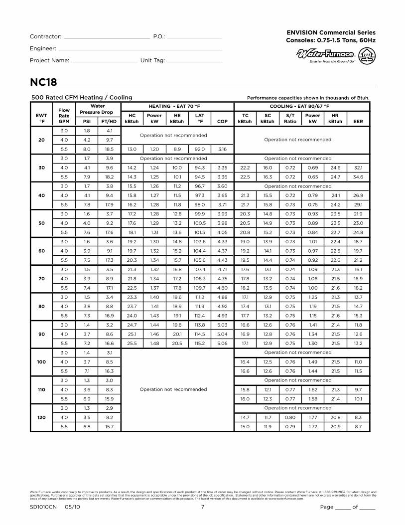
Wiring Schematics CCM - ELECTRONIC THERMOSTAT 208-230-265/60/1
CC
CCM – with Electronic Stat
Cap
Brn
WhtGrn
PSCFan
Motor
Factory low voltage wiring
Temperature Switch
Factory line voltage wiring
Quick connect terminal
Wire nut
Notes:1. Switch Red and Blue wires for 208 volt operationField low voltage wiring
Field line voltage wiring
LP
HP
Handi - Box
Ground Lug
HL
Cycled
Continuous
CCT2 T1
Compressor
C
R
S
Tan (33)
Red Blk
Blue
L1L2
High
Low
Auto
Fan
6
1
32
4
5
COMPRESSOR CONTROL MODULE
TESTPIN
HP
HP
CC
CG
LO
RC
LPLP
Y
HP
HP
CC
CG
LO
RC
LPLP
Y
Transformer
24V
Blue230V265V
Red208V
Black
Yellow Black/White
Black/White (1)
Red (2)
Brown (3)
Black (6)
Black (7)
Blue (8)Blue (9)
Ther
m istor
Electronic THERMOSTAT
T1
T3
B Cool
A Heat
T2
T4
T6
T5
SHUT
DOWN
24 V
AC
INPUT
T6
T4
T5
T2
T1
T3O
veride
Shut dow
n
J1Black
Violet (5)
Violet (4)
Yellow (13)
Yellow (10)
White (20)
Orange (14) Orange (21)
Black (29)
Red (30)
Black
Black (12)
White (18)
Red (11)
Red (19)
Red (17)
24 V Accessory
24VACShutdown
Red (15)
Red (16)
NOTE 1
T
ST
CC - Compressor Contactor
HP - High Pressure SwitchLP - Low Pressure Switch
RV - Reversing Valve CoilST - Entering Air Temperature Sensor
RB - Blower Relay
Black
Black
Red (11)
Black (12)
Red (17)
Red (19)
Black (25)
White (28)
Black (31)Red (32)
Brown (26)
RB
4 2
5
Red
RV
DT
ON
OFF
Damper Sw
Damper Motor
D
Fan Mode Sw
Blk/Wht (24)
Blk/Wht (23)
Black (22)
White (18 )
Blue (T6)
NOTE 2
2. Terminal C of 24 V PB is used as “L”output for Brown wire 3 for Lockout.
31RB Violet (4)
Blue/Wht (36) Blue/Wht (35)
White (34)
Green (00)
FS
Yellow (13)
Not Used
Violet (5)
Yellow (13)
Yellow (10)
Legend
Console Unit – Wiring Schematic 208-230-265/60/1
6/10/08
Black (22)
White (28)
Black (27)
Brown (26)
DT - Damper Terminal Block
PB - Power Block
PB
1
2
3
Field wire lug
Earth Ground
Relay Contacts -N.O., N.C.
Polarized connector
132
P
Switch - High Pressure
Switch - Low Pressure
Relay coil
Capacitor
Thermistor
HP
LP
T
L1
NOTE 3
3. Optional field installed freeze sensing device.
FS - Freeze Sensing Device
G
UnitPower Supply
208-230/60/1 or265-277/60/1

WaterFurnace works continually to improve its products. As a result, the design and specifications of each product at the time of order may be changed without notice. Please contact WaterFurnace at 1-888-929-2837 for latest design and specifications. Purchaser’s approval of this data set signifies that the equipment is acceptable under the provisions of the job specification. Statements and other information contained herein are not express warranties and do not form the basis of any bargain between the parties, but are merely WaterFurnace’s opinion or commendation of its products. The latest version of this document is available at www.waterfurnace.com.
Contractor: P.O.: Engineer:
Project Name: Unit Tag:
SD1010CN 05/10 11 Page _____ of _____
ENVISION Commercial Series Consoles: 0.75-1.5 Tons, 60Hz
CCM w/EH - ELECTRONIC THERMOSTAT
Wiring Schematics cont.208-230-265/60/1
CC
CCM – with Electronic Stat
Cap
Brn
WhtGrn
PSCFan
Motor
Factory low voltage wiring
Temperature Switch
Factory line voltage wiring
Quick connect terminal
Wire nut
Notes:1. Switch Red and Blue wires for 208 volt operationField low voltage wiring
Field line voltage wiring
LP
HP
Handi - Box
Ground Lug
HL
Cycled
Continuous
CCT2 T1
Compressor
C
R
S
Tan (33)
Red Blk
Blue
L1L2
High
Low
Auto
Fan
6
1
32
4
5
COMPRESSOR CONTROL MODULE
TESTPIN
HP
HP
CC
CG
LO
RC
LPLP
Y
HP
HP
CC
CG
LO
RC
LPLP
Y
Transformer
24V
Blue230V265V
Red208V
Black
Yellow Black/White
Black/White (1)
Red (2)
Brown (3)
Black (6)
Black (7)
Blue (8)Blue (9)
Ther
m istor
Electronic THERMOSTAT
T1
T3
B Cool
A Heat
T2
T4
T6
T5
SHUT
DOWN
24 V
AC
INPUT
T6
T4
T5
T2
T1
T3O
veride
Shut dow
n
J1Black
Violet (5)
Violet (4)
Yellow (13)
Yellow (10)
White (20)
Orange (14) Orange (21)
Black (29)
Red (30)
Black
Black (12)
White (18)
Red (11)
Red (19)
Red (17)
24 V Accessory
24VACShutdown
Red (15)
Red (16)
NOTE 1
T
ST
CC - Compressor Contactor
HP - High Pressure SwitchLP - Low Pressure Switch
RV - Reversing Valve CoilST - Entering Air Temperature Sensor
RB - Blower Relay
Black
Black
Red (11)
Black (12)
Red (17)
Red (19)
Black (25)
White (28)
Black (31)Red (32)
Brown (26)
RB
4 2
5
Red
RV
DT
ON
OFF
Damper Sw
Damper Motor
D
Fan Mode Sw
Blk/Wht (24)
Blk/Wht (23)
Black (22)
White (18 )
Blue (T6)
NOTE 2
2. Terminal C of 24 V PB is used as “L”output for Brown wire 3 for Lockout.
31RB Violet (4)
Blue/Wht (36) Blue/Wht (35)
White (34)
Green (00)
FS
Yellow (13)
Not Used
Violet (5)
Yellow (13)
Yellow (10)
Legend
Console Unit – Wiring Schematic 208-230-265/60/1
6/10/08
Black (22)
White (28)
Black (27)
Brown (26)
DT - Damper Terminal Block
PB - Power Block
PB
1
2
3
Field wire lug
Earth Ground
Relay Contacts -N.O., N.C.
Polarized connector
132
P
Switch - High Pressure
Switch - Low Pressure
Relay coil
Capacitor
Thermistor
HP
LP
T
L1
NOTE 3
3. Optional field installed freeze sensing device.
FS - Freeze Sensing Device
G
UnitPower Supply
208-230/60/1 or265-277/60/1

WaterFurnace works continually to improve its products. As a result, the design and specifications of each product at the time of order may be changed without notice. Please contact WaterFurnace at 1-888-929-2837 for latest design and specifications. Purchaser’s approval of this data set signifies that the equipment is acceptable under the provisions of the job specification. Statements and other information contained herein are not express warranties and do not form the basis of any bargain between the parties, but are merely WaterFurnace’s opinion or commendation of its products. The latest version of this document is available at www.waterfurnace.com.
Contractor: P.O.: Engineer:
Project Name: Unit Tag:
SD1010CN 05/10 12 Page _____ of _____
ENVISION Commercial Series Consoles: 0.75-1.5 Tons, 60Hz
Operational Logic TableModeHtgClg
Inputs Fan Comp RVY
Y,OFan G ON
ONON
OFFONON
OFFONOFF
SW1 - #4 On, SW2 OffDrain pan overflow lockout
FS thermistor ( loop <15°F, well < 30°F) lockoutHigh pressure >600 PSI lockout Low pressure < 40 PSI lockout Not usedMicroprocessor malfunction*Not UsedSW2 status (Off = down position, On = up position)
DrainWater Flow High PressLow PressAir FlowStatusDHW LimitHWD
LED Normal Display Mode
SW1- #4 On, SW2 OnDrain pan overflow FS thermistor (loop <15°F, well <30°F) High pressure > 600 PSI Low pressure < 40 PSINot usedNot usedNot usedSW2 in the On position
Current Fault StatusSW1- #4 Off, SW2 Off
YGO
ESNSLS
Not UsedOff position
Inputs
CompressorFANO
ESNSLS
Not UsedOn position
OutputsDiagnostic Modes
SW1- # 4 Off, SW2 OnDrainWater Flow High PressLow PressAir FlowStatusDHW LimitHWD
LED
LED Display Mode Table
CC RelayFan Relay
CCCCG
CC
RR
FAN FANCOM
R C Y O G LO ES NS LS
P3
P1
SW1MicroprocessorLogic Control17P529A01
P2
61
72
83
94
105
Versatec Logic Board Physical Layout
Switch OFF ON
SW1 - 1
SW1 - 2
SW1 - 3
SW1 - 4
SW1 - 5
SW2
Test - Selected timings sped up to facilitatetroubleshooting
Loop - Closed loop freeze sensing setting (15°F)
IO Display * - Enables Input/Output display on externalLED board*
Enables NS features
Motorized Valve - 1.5 minute compressor on delay
OFF * - Normal or Input display mode activatedON * - Current fault or Output displaymode activated
Normal - Standard timings
Well - Open loop freeze sensing setting (30°F)
Normal * - Unit status display
Normal - Standard thermostat operation
Normal - Standard delay on call fromcompressor used
*Refer to LED Display Mode table for position of SW1-4 and SW2
Logic Board DIP Switch Settings
Normal Control Timing TableBlower off delayCompressor on delayShort cycle delayMinimum compressor on timeHigh pressure fault recognition delayLow pressure fault recognition delay
Condensate overflow fault recognition delayLow pressure fault bypass delayFreeze sensing fault bypass delayMotorized valve delayRandom start delay
Freeze sensing fault recognition delay
30 seconds10 seconds5 minutes60 seconds (except for fault condition )Less than 1 second30 seconds30 seconds30 seconds2 minutes2 minutes90 seconds0 - 25 seconds
Test Control Timing TableBlower off delayCompressor on delayShort cycle delayMinimum compressor on timeHigh pressure fault recognition delayLow pressure fault recognition delay
Condensate overflow fault recognition delayLow pressure fault bypass delayFreeze sensing fault bypass delayMotorized valve delayRandom start delay
Freeze sensing fault recognition delay
5 seconds2 seconds15 seconds5 seconds (except for fault condition )Less than 1 second30 seconds30 seconds30 seconds0 seconds0 seconds90 seconds0 seconds
*Flashing Status light indicates microprocessor is functioning properly. Solid "on" indicates a microprocessor malfunction.
Wiring Schematics cont.208-230-265/60/1VERSATEC CONTROL - EH & REMOTE WALL THERMOSTAT
Legend for Schematic [A]

WaterFurnace works continually to improve its products. As a result, the design and specifications of each product at the time of order may be changed without notice. Please contact WaterFurnace at 1-888-929-2837 for latest design and specifications. Purchaser’s approval of this data set signifies that the equipment is acceptable under the provisions of the job specification. Statements and other information contained herein are not express warranties and do not form the basis of any bargain between the parties, but are merely WaterFurnace’s opinion or commendation of its products. The latest version of this document is available at www.waterfurnace.com.
Contractor: P.O.: Engineer:
Project Name: Unit Tag:
SD1010CN 05/10 13 Page _____ of _____
ENVISION Commercial Series Consoles: 0.75-1.5 Tons, 60Hz
Wiring Schematics cont.208-230-265/60/1VERSATEC CONTROL - EH & REMOTE WALL THERMOSTAT
Schematic [A]
Transformer
24V
Cap
Brn/Wht
BrnGrn
H L
PSCFan
Motor
CC
T2 T1
Compressor
C
R
S
Tan (36)
Red
Blu
L1L 2
Relay Contacts-N.O., N.C.
Thermistor
Relay coil
Switch - High pressure
Switch - Low pressure
Polarized connector
Condensate Overflow
Factory low voltage wiringFactory line voltage wiringField low voltage wiringField line voltage wiring
Internal junction
Quick connect terminal
Wire nut
Field wire lug
Ground
L1
Legend
5 - Switch blue and red wires for 208V operation.
T
132
P
Notes:1 - Requires common connection or 24 VAC for activation.
NOTE 5Red 208V
Blue 230V
Blk
Black(27)
R
C
C
R
CC
CCG
OnOff
Test / NormalLoop / Well
P2
P1
SW1
Inputs / NormalOutputs / Normal
12345 Motorized Valve / Normal
FAN
FAN
CO
M
CPU
FS
LP
HP
RV
CO
LSNSESLOGOYCR
Yellow
Black/White
T
Black (47)162738495
10
DC voltage PCB traces
High Low
Fan SpeedSwitch
RB
Blue 265V
4 - Check installlation wiring information for specific thermostat hookup instructions.
RedBlack (25)
RB
Gray (42)
White (28)Black(29)
Red (30)
Damper Motor
Off
On
DAMPER MODE
DTD
Blue/Wht (35)
MV
Black (31)Red (32)
Handi - Box
Ground Lug
UnitPower Supply208-230 /60/1 or265-277/60/1
G
CR Y1 O G L S
Terminal BoardX2 X1 W1
Red
Blac
k
Yel
low
Ora
nge
Bro
wn
Gre
en
NOTE 2
Vio
let
Pin
k
Blue
1 3
4 2
NOTE 1
ES – Emergency Shutdown
Black/White
Black/White
Black Com
E1
EH
T2 T1
L1
WhiteWhite
L2
Blue (40)
LS1LS2
Black
Tan (41)
E1
4
2
5
Black (37)
Blue (38)
Red (39)
AQNOTE 3
White
2 - When field installed 24VAC motorized valve is used, connect to C and Y or SV terminals.
3 - Optional field installed aquastat for use with single heat
Blue/Wht (36)
Black (46)Blue (45 )Blue (44)Brown(43)
Orange (42)Orange (41 )
YellowYellow
Green (00)
Black (22) Orange (21)
EH
CC
White (34)
Brown (43)
Legend
Microprocessor – with Remote Wall Stat & Electric Heat
Console Unit – Wiring Schematic 208-230-265/60/1
97P786-04 6/10/08
EH – Electric Heat Contactor
AQ – AquastatCC – Compressor ContactorCO – Condensate Overflow
E1 – Electric Heat Relay
FS – Freeze Sensing DeviceHP – High Pressure SwitchLP – Low Pressure SwitchLS – Loadshed
NS – Night SetbackRB – Blower Power RelayRV – Reversing Valve CoilSW1 – DIP Switch #1
MV – Motorized Valve
Red(19)
DT – Damper Terminal Block

WaterFurnace works continually to improve its products. As a result, the design and specifications of each product at the time of order may be changed without notice. Please contact WaterFurnace at 1-888-929-2837 for latest design and specifications. Purchaser’s approval of this data set signifies that the equipment is acceptable under the provisions of the job specification. Statements and other information contained herein are not express warranties and do not form the basis of any bargain between the parties, but are merely WaterFurnace’s opinion or commendation of its products. The latest version of this document is available at www.waterfurnace.com.
Contractor: P.O.: Engineer:
Project Name: Unit Tag:
SD1010CN 05/10 14 Page _____ of _____
ENVISION Commercial Series Consoles: 0.75-1.5 Tons, 60Hz
Transformer
Blue 240V
Red 208V
Black
Blk/Wht
Black
DA T
HP
RB
RV
CC
NOTE 1277V
FS T
CO
Yellow
PB1
L1
L2
OS
NOTE 2 CP/FP
DF/AP
L1
L2
PB2
NOTE 3
NOTE 4
NOTE 5
Compressor
CC
T2
R
S
C
BlkRed
Tan
Blu
L2
T1
L1
Handi - Box
Ground Lug
UnitPower Supply208-230/60/1 or265-277/60/1
G
Black
Red
Cap
Brn/Wht
BrnGrn
H L
PSCFan
Motor
High Low
Fan SpeedSwitch
RB
ES
LP
11 K
Johnson FX-10
5VDC
AI3
23
24
25
26
27
28
29
30
31
32
33
34
35
36
37
38
+
-
AI5-
+
AI4-
+
AI6
AI2
AI1
5VDC
5VDC
LED
-
-
-
+
+
+
24VAC
24VAC
Com
GR
OU
ND
39
40
41
PWM2
PWM2 Com
PWM1
42
43
44
45
46
47
48
24VAC Com
DI12
DI11
DI10
DI9
DI8
DI7
49
50
51
52
53
54
55
56
DI 3/4 /5/6/ Com
DI6
DI5
DI4
DI3
DI2
DI1
9VDC
20
19
18
17
16
15
14
13
12
11
10
9
8
7
6
5
4
3
1
D09
D08
D07
D06
D05
D04
D03
D02
D01
J8
J2
J10
J9
J7
A32
A31
A35
A14
A24
A34
A33
A15
TThermistor - Johnson Control
Relay coil
Switch - High pressure
Switch - Low pressure
Polarized connector
Condensate Overflow
132
P
Factory low voltage wiringFactory line voltage wiringField low voltage wiringField line voltage wiring
Internal junction
Quick connect terminal
Wire nut
Field wire lug
Ground
Notes:
L1
1 - Switch Blue and Red wires for 208V operation Relay Contacts-
N.O., N.C.2 - Disconnect for 15 degree freeze protection
Field Zone Sensor Wiring3 - Acc 1 output is cycled with the compressor.4 - Acc 2 output is cycled with the fan.5 - R, C, Y1, O, and G inputs are for use with a wall mounted thermostat.
A23
A13
A11
A21A
12
A25A22
Open Jumper
Closed Jumper
2
TB
R
C
Y1
O
G
L
X1
X2
24VAC
24V COM
Alarm
Acc 1
Acc 2
Fan
Rev Valve
Comp
SS
AIC
RS
SC
TO
Setpoint Shift
AI Com
Room Sensor
Sensor Com
Temp Occ
EHC
T2 T1
L1L2
Blue
WhiteWhite
LS1 LS2
Black (6)
Blue (4)
MEHS
EHC
MolexPlug
White
Black
Blk/Red (9)
White (5)Wht/Blu (6)
Brown (2)
Black (22)
Blk/Wht (29)
Blue (27)Blue (32)
Yellow (35)Blk/Wht (36)
Black (6)
Black (6)
Yellow (33)Black (34)
Black(121)Black (515)
Black (131)
Brown (1)
Gry/Wht (14)
Orange (30)
Pink (28 )
Red (24 )
Violet (23)
Black (31)
Green (37)
Yellow
Yellow (16)
Red (20)
Black (1)
Black (2 )
Orange (7)
Black (12)
Gray (3)
Black (5)
Yellow (9)
Black (310 )
Black (111 )
Blk Red
LC1
LC2
MolexPlug
TAN
BLUE
Blk
Blk
Blk/Wht
Orange
White
Black (310)
Black (111)
Gray (26 )
Org/Wht (12)
Org/Bck (11)
Blu/Wht (10)
Yellow (21)
Orange (19)
Green (17)
Red (120)
Red (120)
FX10 – with Electric Heat
Console Unit – Wiring Schematic 208-230-265/60/1 97PXXX -XX
LegendCC - Compressor ContactorCO - Condensate OverflowCP/FP - Compressor Proving/Fan ProvingDA - Discharge Air TemperatureDF/AP - Dirty Filter/Air ProvingEHC - Electric Heat ContactorEHR - Electric Heat RelayES - Emergency ShutdownFS - Freeze Sensing DeviceHP - High Pressure SwitchLP - Low Pressure SwitchMEHS - Manual EH SwitchOS - Occupied SwitchRB - Blower Power ReplayRV - Reversing Valve CoilTB - Terminal Block
6/10/08
Wiring Schematics cont.FX10 - EH 208-230-265/60/1

WaterFurnace works continually to improve its products. As a result, the design and specifications of each product at the time of order may be changed without notice. Please contact WaterFurnace at 1-888-929-2837 for latest design and specifications. Purchaser’s approval of this data set signifies that the equipment is acceptable under the provisions of the job specification. Statements and other information contained herein are not express warranties and do not form the basis of any bargain between the parties, but are merely WaterFurnace’s opinion or commendation of its products. The latest version of this document is available at www.waterfurnace.com.
Contractor: P.O.: Engineer:
Project Name: Unit Tag:
SD1010CN 05/10 15 Page _____ of _____
ENVISION Commercial Series Consoles: 0.75-1.5 Tons, 60Hz
NCW09-18
Overall Cabinet
Flat Top
ConfigurationA B C D E F G H I J
Width Depth Height Grille Lid Grille Length
Grille Width
in. 45.0 10.8 25.7 9.2 35.0 6.1 2.3 44.1 10.3 4.3
cm. 114.3 27.3 65.2 23.4 88.9 15.6 5.8 112.0 26.0 10.9
in. 50.0 12.3 25.7 9.2 35.0 6.1 3.3 49.1 11.8 4.3
cm. 127.0 31.1 65.2 23.4 88.9 15.6 8.3 124.7 29.8 10.9
09-12
15-18
F
B
G
I
J
C
ED
A
H
FILTER BRACKET FILTER BRACKET
RIGHT RETURN
TOP
FRONT
LEFT RETURN
DETAIL BTWIST EXTENDEDTAB BACK ANDFORTH UNTILTAB BREAKS OFF(ONLY BREAK-OFFTAB SAME SIDE ASGRILLE LID AS SHOWN)
DETAIL BTWIST EXTENDED TABBACK AND FORTH UNTILTAB BREAKS OFF(ONLY BREAK-OFFTAB SAME SIDE ASGRILLE LID AS SHOWN)
BA
REMOVE PLASTIC STRIPFROM BROKEN TAB ANDREPLACE ON BROKENEDGE OF LEG AS SHOWN
REMOVE PLASTIC STRIPFROM BROKEN TAB ANDREPLACE ON BROKENEDGE OF LEG AS SHOWN
Dimensional Data - Flat Top Cabinet

WaterFurnace works continually to improve its products. As a result, the design and specifications of each product at the time of order may be changed without notice. Please contact WaterFurnace at 1-888-929-2837 for latest design and specifications. Purchaser’s approval of this data set signifies that the equipment is acceptable under the provisions of the job specification. Statements and other information contained herein are not express warranties and do not form the basis of any bargain between the parties, but are merely WaterFurnace’s opinion or commendation of its products. The latest version of this document is available at www.waterfurnace.com.
Contractor: P.O.: Engineer:
Project Name: Unit Tag:
SD1010CN 05/10 16 Page _____ of _____
ENVISION Commercial Series Consoles: 0.75-1.5 Tons, 60Hz
NCS09-18
Overall CabinetSlope Top
ConfigurationA B C D E F G H I J
Width Depth Height Grille Lid Grille Length
Grille Width
in. 45.0 11.1 28.6 9.2 35.0 6.1 2.8 44.1 10.3 4.3cm. 114.3 28.2 72.6 23.4 88.9 15.6 7.2 112.0 26.0 10.9in. 50.0 12.6 29.1 9.2 35.0 6.1 2.5 49.1 11.8 4.3
cm. 127.0 32.0 73.9 23.4 88.9 15.6 6.4 124.7 29.8 10.9
09-12
15-18
REMOVE PLASTIC STRIPFROM BROKEN TAB ANDREPLACE ON BROKENEDGE OF LEG AS SHOWN
H I
J
C
F
E
A
D
G
B
RIGHT RETURN
TOP
FRONT
LEFT RETURN
DETAIL BTWIST EXTENDED TABBACK AND FORTH UNTILTAB BREAKS OFF(ONLY BREAK-OFFTAB SAME SIDE ASGRILLE LID AS SHOWN)
DETAIL ATWIST EXTENDED TABBACK AND FORTH UNTILTAB BREAKS OFF(ONLY BREAK-OFFTAB SAME SIDE ASGRILLE LID AS SHOWN)
REMOVE PLASTIC STRIPFROM BROKEN TAB ANDREPLACE ON BROKENEDGE OF LEG AS SHOWN
BA
FILTER BRACKETFILTER BRACKET
Dimensional Data - Slope Top Cabinet

WaterFurnace works continually to improve its products. As a result, the design and specifications of each product at the time of order may be changed without notice. Please contact WaterFurnace at 1-888-929-2837 for latest design and specifications. Purchaser’s approval of this data set signifies that the equipment is acceptable under the provisions of the job specification. Statements and other information contained herein are not express warranties and do not form the basis of any bargain between the parties, but are merely WaterFurnace’s opinion or commendation of its products. The latest version of this document is available at www.waterfurnace.com.
Contractor: P.O.: Engineer:
Project Name: Unit Tag:
SD1010CN 05/10 17 Page _____ of _____
ENVISION Commercial Series Consoles: 0.75-1.5 Tons, 60Hz
NCE09-18
REMOVE PLASTIC STRIPFROM BROKEN TAB ANDREPLACE ON BROKENEDGE OF LEG AS SHOWN
Overall CabinetExt. Slope Top
Configuration A B C D E F G H I JWidth Depth Height Grille Lid Grille
LengthGrille Width
in. 50.0 12.6 29.1 9.2 35.0 6.1 2.4 49.1 12.0 4.3cm. 127.0 32.0 73.9 23.4 88.9 15.6 6.1 124.7 30.5 10.9in. 55.0 12.6 29.1 9.2 35.0 6.1 2.5 54.1 11.8 4.3
cm. 139.7 32.0 73.9 23.4 88.9 15.6 6.4 137.4 29.8 10.9
09-12
15-18
FILTER BRACKETFILTER BRACKET
A
D E
C
H I
J
F
B
G
A B
RIGHT RETURN TOP
FRONT
LEFT RETURN
DETAIL BTWIST EXTENDED TABBACK AND FORTH UNTILTAB BREAKS OFF(ONLY BREAK-OFFTAB SAME SIDE ASGRILLE LID AS SHOWN)
DETAIL ATWIST EXTENDED TABBACK AND FORTH UNTILTAB BREAKS OFF(ONLY BREAK-OFFTAB SAME SIDE ASGRILLE LID AS SHOWN)
REMOVE PLASTIC STRIPFROM BROKEN TAB ANDREPLACE ON BROKENEDGE OF LEG AS SHOWN
Dimensional Data - Extended Slope Top Cabinet

WaterFurnace works continually to improve its products. As a result, the design and specifications of each product at the time of order may be changed without notice. Please contact WaterFurnace at 1-888-929-2837 for latest design and specifications. Purchaser’s approval of this data set signifies that the equipment is acceptable under the provisions of the job specification. Statements and other information contained herein are not express warranties and do not form the basis of any bargain between the parties, but are merely WaterFurnace’s opinion or commendation of its products. The latest version of this document is available at www.waterfurnace.com.
Contractor: P.O.: Engineer:
Project Name: Unit Tag:
SD1010CN 05/10 18 Page _____ of _____
ENVISION Commercial Series Consoles: 0.75-1.5 Tons, 60Hz
CONTROL PANEL(REMOVE FOR ACCESSTO CONTROL BOX)
DAMPER ON/OFF SWITCH
COMPRESSORACCESS PANELREMOVED FORCLARITY(BOTH SIDES)
ELECTRIC HEAT MODENORMAL/BOILERLESSSWITCH (OPTIONAL)
FAN OPTION SWITCH
OPTIONAL BACK PLATE(REQUIRED FORDAMPER INSTALLATION)
OUTSIDE AIRDAMPER OPTION(FIELD INSTALLED)
LOW VOLTAGETERMINALS(FX10 & REMOTE WALLSTAT OPTIONS ONLY)
OPTIONALFUSED/NON-FUSEDDISCONNECT
OPTIONALBALL VALVES
OPTIONALHOSE KITS
CONDENSATEDRAIN CONNECTION
FILTER
HANDY BOX
Dimensional Data - Right Return Controls Detail

WaterFurnace works continually to improve its products. As a result, the design and specifications of each product at the time of order may be changed without notice. Please contact WaterFurnace at 1-888-929-2837 for latest design and specifications. Purchaser’s approval of this data set signifies that the equipment is acceptable under the provisions of the job specification. Statements and other information contained herein are not express warranties and do not form the basis of any bargain between the parties, but are merely WaterFurnace’s opinion or commendation of its products. The latest version of this document is available at www.waterfurnace.com.
Contractor: P.O.: Engineer:
Project Name: Unit Tag:
SD1010CN 05/10 19 Page _____ of _____
ENVISION Commercial Series Consoles: 0.75-1.5 Tons, 60Hz
BLOWER ACCESS PANEL
COMPRESSORACCESS PANEL
37.88(96.2)
28.5(72.4)
1.5(3.8)
1.5(3.8)
4.37(11.1)
9.38(23.8)
FILTER
CONTROL PANEL
25.25(64.1)
0.86(2.2)
10.31(26.2)
1.0(2.5)
1.78(4.5)
11.0(27.9)
4.5(11.4)
2.0(5.1)
21.4(54.4)
20.0(50.8)
CONDENSATEDRAIN CONNECTION
WATER OUT 1/2˝ FPT
WATER IN 1/2˝ FPT
OPTIONAL BACK PLATE
COMPRESSORACCESS PANEL
43.37(110.2)
28.0(71.1)
9.25(23.5)
13.9(35.3)
25.65(65.2)
19.83(50.4)
1.64(4.2)
12.03(30.6)
0.66(1.7)
2.75(7.0)
5.5(14.0) DAMPER OPENING
Models 09-12
BLOWER ACCESS PANEL
COMPRESSORACCESS PANEL
42.88(108.9)
34.0(86.4)
1.5(3.8)
1.5(3.8)
4.32(11.0)
8.88(22.6)
FILTER
CONTROL PANEL
25.25(64.1)
0.86(2.2)
11.75(29.8)
1.0(2.5)
12.0(30.5)
4.5(11.4)
2.0(5.1)
20.6(52.3)
19.5(49.5)
CONDENSATEDRAIN CONNECTION
WATER OUT 1/2˝ FPT
WATER IN 1/2˝ FPT
OPTIONAL BACK PLATE
COMPRESSORACCESS PANEL
48.25(122.6)
33.0(83.8)
11.78(29.9)
13.9(35.3)
25.80(65.5)
20.0(50.8)
1.62(4.1)
12.18(30.9)
0.83(2.1)
2.75(7.0)
5.4(13.7) DAMPER OPENING
Models 15-18
Dimensional Data - Right Return ChassisData = inches (cm)

WaterFurnace works continually to improve its products. As a result, the design and specifications of each product at the time of order may be changed without notice. Please contact WaterFurnace at 1-888-929-2837 for latest design and specifications. Purchaser’s approval of this data set signifies that the equipment is acceptable under the provisions of the job specification. Statements and other information contained herein are not express warranties and do not form the basis of any bargain between the parties, but are merely WaterFurnace’s opinion or commendation of its products. The latest version of this document is available at www.waterfurnace.com.
Contractor: P.O.: Engineer:
Project Name: Unit Tag:
SD1010CN 05/10 20 Page _____ of _____
ENVISION Commercial Series Consoles: 0.75-1.5 Tons, 60Hz
LOW VOLTAGETERMINALS(FX10 & REMOTE WALLSTAT OPTIONS ONLY)
OPTIONALFUSED/NON-FUSEDDISCONNECT
OPTIONALBALL VALVES
OPTIONALHOSE KITS
CONDENSATEDRAIN CONNECTION
FILTER
HANDY BOX
OPTIONALELECTRIC HEAT
OPTIONAL BACK PLATE(REQUIRED FORDAMPER INSTALLATION)
OUTSIDE AIRDAMPER OPTION(FIELD INSTALLED)
CONTROL PANEL(REMOVE FOR ACCESSTO CONTROL BOX)
DAMPER ON/OFF SWITCH
COMPRESSORACCESS PANELREMOVED FORCLARITY(BOTH SIDES)
ELECTRIC HEAT MODENORMAL/BOILERLESSSWITCH (OPTIONAL)
FAN OPTION SWITCH
Dimensional Data - Left Return Controls Detail

WaterFurnace works continually to improve its products. As a result, the design and specifications of each product at the time of order may be changed without notice. Please contact WaterFurnace at 1-888-929-2837 for latest design and specifications. Purchaser’s approval of this data set signifies that the equipment is acceptable under the provisions of the job specification. Statements and other information contained herein are not express warranties and do not form the basis of any bargain between the parties, but are merely WaterFurnace’s opinion or commendation of its products. The latest version of this document is available at www.waterfurnace.com.
Contractor: P.O.: Engineer:
Project Name: Unit Tag:
SD1010CN 05/10 21 Page _____ of _____
ENVISION Commercial Series Consoles: 0.75-1.5 Tons, 60Hz
9.38(23.8)
28.5(72.4)
1.50(3.8)
1.50(3.8)
4.37(11.1)
37.88(96.2)
BLOWER ACCESS PANEL
COMPRESSORACCESS PANEL
FILTER
CONTROL PANEL
1.00(2.5)
10.31(26.2)
4.5(11.4)
0.86(2.2)
2.0(5.1)
25.25(64.1)
21.4(54.4)
20.0(50.8)
1.78(4.5)
11.0(27.9)
CONDENSATEDRAIN CONNECTION
WATER OUT 1/2˝ FPT
WATER IN 1/2˝ FPT
28.00(71.1)
13.90(35.3)
9.25(23.5)
2.75(7.0)
12.03(30.5)
0.66(1.7)
5.50(14.0)
OPTIONAL BACK PLATE
COMPRESSORACCESS PANEL
DAMPER OPENING
43.37(110.2)
1.62(4.1)
25.65(65.1)
19.83(50.4)
Models 09-12
8.88(22.6)
34.0(86.4)
1.50(3.8)
1.50(3.8)
4.32(11.0)
42.88(108.9)
BLOWER ACCESS PANEL
COMPRESSORACCESS PANEL
FILTER
CONTROL PANEL
1.00(2.5)
11.75(26.2)
4.5(11.4)
0.86(2.2)
2.0(5.1)
25.25(64.1)
20.6(52.3)
19.5(49.5)
12.0(30.5)
CONDENSATEDRAIN CONNECTION
WATER OUT 1/2˝ FPTWATER IN 1/2˝ FPT
33.0(83.8)
13.90(35.3)
11.78(29.9)
2.75(7.0)
12.18(30.9)
0.83(2.1)
5.50(14.0)
OPTIONAL BACK PLATE
COMPRESSORACCESS PANEL
DAMPER OPENING
48.25(122.6)
1.62(4.1)
25.80(65.5)
20.0(50.8)
Models 15-18
Dimensional Data - Left Return ChassisData = inches (cm)

WaterFurnace works continually to improve its products. As a result, the design and specifications of each product at the time of order may be changed without notice. Please contact WaterFurnace at 1-888-929-2837 for latest design and specifications. Purchaser’s approval of this data set signifies that the equipment is acceptable under the provisions of the job specification. Statements and other information contained herein are not express warranties and do not form the basis of any bargain between the parties, but are merely WaterFurnace’s opinion or commendation of its products. The latest version of this document is available at www.waterfurnace.com.
Contractor: P.O.: Engineer:
Project Name: Unit Tag:
SD1010CN 05/10 22 Page _____ of _____
ENVISION Commercial Series Consoles: 0.75-1.5 Tons, 60Hz
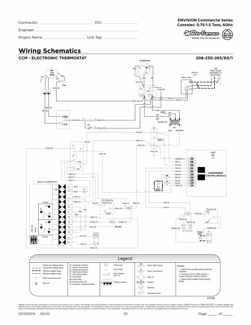
Engineering Guide Specifications
GeneralFurnish and install WaterFurnace Water Source Heat Pumps,
as indicated on the plans. Equipment shall be completely
assembled, piped and internally wired. Chassis shall be
installed with factory built cabinet or other custom cabinet
approved by WaterFurnace engineering. Chassis SHALL
NOT be installed without an approved cabinet enclosure.
Capacities and characteristics as listed in the schedule and
the specifications that follow. The reverse cycle heating/
cooling units shall be floor mounted console type with hori-
zontal air inlet and up-flow air discharge. Units shall be ARI/
ISO 13256-1 certified and listed by a nationally recognized
safety-testing laboratory or agency, such as ETL Testing
Laboratory. Each unit shall be computer run-tested at the
factory with conditioned water and operation verified to
catalog data. Each unit shall be mounted on a pallet and
shipped in a corrugated box or stretch-wrapped. The units
shall be designed to operate with entering liquid tempera-
ture between 20°F and 120°F [-6.7°C and 48.9°C].
Chassis & Cabinet
The cabinet shall be fabricated from heavy-gauge galva-
nized steel and finished with a beige textured epoxy powder
coating on both sides for added protection. This corrosion
protection system shall meet the stringent 1000 hour salt
spray test per ASTM B117.
The cabinet shall be easily removable to allow for ease of
service to the controls compartment, chassis, and piping.
The top of the cabinet and grille is a horizontally flat (op-
tional sloped) surface with a hinged control door cover. The
return air filter shall be 1” (25.4 mm) fiberglass disposable
type media.
The return and supply air sections are insulated with a 1/4”
(6.4 mm) thick, dual density, 2 lb/ft3 (32 kg/m3) coated
mat glass fiber with edges sealed or tucked under flanges
to prevent the introduction of glass fibers into the discharge
supply air through the aluminum grille. Standard cabinet
panel insulation must meet NFPA 90A requirements, air
erosion and mold growth limits of UL-181, stringent fungal
resistance test per ASTM-C1071 and ASTM G21, and shall
meet zero level bacteria growth per ASTM G22. Unit insula-
tion must meet these stringent requirements or unit(s) will
not be accepted.
Option: A Super Quiet Sound package shall include multi-
density full coverage compressor blanket.
Option: Shipped with motorized outside air damper and damper assembly for 25% make-up air.
The drain pan shall be of stainless steel construction to
inhibit corrosion and bacterial growth. Drain outlet shall
be located on pan as to allow complete and unobstructed
drainage of condensate. The unit as standard will be sup-
plied with solid-state electronic condensate overflow
protection with microprocessor or FX10 option. Mechanical
float switches WILL NOT be accepted. Condensate tube
shall be constructed of stainless steel and have an internal
factory installed condensate trap.
Refrigerant Circuit
All units shall utilize the non-ozone depleting and low global
warming potential refrigerant R410A. All units shall contain
a sealed refrigerant circuit including a hermetic motor-com-
pressor, bi-directional thermostatic expansion valve, finned
tube air-to-refrigerant heat exchanger, reversing valve, co-
axial tube water-to-refrigerant heat exchanger, and service
ports.
Compressors shall be high-efficiency single speed rotary
type designed for heat pump duty and mounted on du-
rometer grommets to provide vibration free compressor
mounting. Compressor motors shall be single-phase PSC
with external overload protection.
The air coil shall be sized for low-face velocity and con-
structed of lanced aluminum fins bonded to rifled copper
tubes in a staggered pattern not less than three rows deep
for enhanced performance.
Option: FormiShieldTM air coil coating for maximum protec-
tion against formicary corrosion.
The coaxial water-to-refrigerant heat exchanger shall be
designed for low water pressure drop and constructed of
a convoluted copper (cupronickel option) inner tube and
a steel outer tube. Refrigerant to air heat exchangers shall
utilize enhanced corrugated lanced aluminum fins and rifled
copper tube construction rated to withstand 600 PSIG
(4135 kPa) refrigerant working pressure. Refrigerant to
water heat exchangers shall be of copper inner water tube
and steel refrigerant outer tube design, rated to withstand
600 PSIG (4135 kPa) working refrigerant pressure and 450
PSIG (3101 kPa) working water pressure. The thermostatic
expansion valve shall provide proper superheat over the
entire liquid temperature range with minimal “hunting.” The
valve shall operate bi-directionally without the use of check
valves.

WaterFurnace works continually to improve its products. As a result, the design and specifications of each product at the time of order may be changed without notice. Please contact WaterFurnace at 1-888-929-2837 for latest design and specifications. Purchaser’s approval of this data set signifies that the equipment is acceptable under the provisions of the job specification. Statements and other information contained herein are not express warranties and do not form the basis of any bargain between the parties, but are merely WaterFurnace’s opinion or commendation of its products. The latest version of this document is available at www.waterfurnace.com.
Contractor: P.O.: Engineer:
Project Name: Unit Tag:
SD1010CN 05/10 23 Page _____ of _____
ENVISION Commercial Series Consoles: 0.75-1.5 Tons, 60Hz
Option: Cupro-nickel refrigerant to water heat exchanger shall be of copper-nickel inner water tube and steel refriger-
ant outer tube design, rated to withstand 600 PSIG (4135 kPa) working refrigerant pressure and 450 PSIG (3101 kPa) working water pressure. Water lines shall also be of cupron-
ickel construction.
Option: Insulated water-to-refrigerant heat exchanger, water lines and refrigerant suction lines shall be insulated to prevent condensation at low liquid temperatures below 50°F.
Fan Motor & Assembly
The fan shall be a direct drive centrifugal type with a twin
dynamically balanced wheel. The housing and wheel shall
be designed for quiet, low outlet velocity operation. The fan
housing shall be constructed of galvanized steel and shall
be removable from the unit for servicing of the fan mo-
tor. The fan motor shall be a two-speed type and shall be
isolated from the housing by rubber grommets. The motor
shall be permanently lubricated and have thermal overload
protection.
ElectricalA control box shall be located within the unit compressor compartment and shall contain a 75VA transformer, 24 Volt activated, 2 pole compressor contactor, and solid-state controller for complete unit operation. Units shall be name-plated for use with time delay fuses or HACR circuit break-ers. Unit controls shall be 24 Volt and provide heating or cooling as required by the remote thermostat/sensor.
Unit mounted controls shall consist of switches for “OFF”,
“FAN”, and “AUTO” or “HEAT/COOL”. An additional switch
is provided for fan speed setting of “HI” or “LO”. The unit
shall be equipped with a fan switch on the side of the con-
trol to provide “CONTINUOUS” or “CYCLED” fan operation.
“CYCLED” fan will turn the fan on with the compressor. A
unit-mounted electronic thermostat with a remote electron-
ic thermistor located in the return air will control compres-
sor operation in heating and cooling modes. Unit mounted
thermostat shall be the standard thermostat option. All unit
mounted thermostats shall be auto changeover. Manual
changeover WILL NOT be accepted. Electro-mechanical
operation WILL NOT be accepted.
ControlsStandard: A compressor control module (CCM) shall be
included to disable compressor operation in the event of
a trip of any of the safety switches and to send a signal to
activate a fault indicator light at the thermostat. The CCM
shall be capable of being reset from the thermostat or from
the unit main disconnect switch. A terminal block with
screw terminals shall be provided for field connection of all low-voltage wiring.
Option: Versatec microprocessor-based controller will
provide operational sequencing; high and low pressure
switch monitoring, freeze sensing, lockout mode control,
emergency shutdown mode, random start, short cycle pro-
tection, LED mode and fault indicators, fault memory, input
and output diagnostics, and field selectable options, and
condensate overflow sensing.
Option: FX10 microprocessor-based controller that inter-
faces with an electronic thermostat to monitor and con-
trol unit operation. The control shall provide operational
sequencing, fan speed control, high, low and loss of charge
pressure monitoring, freeze sensing, condensate overflow
sensing, lockout mode control, fault memory, field select-
able options. The control shall communicate all mode, sta-
tus, fault and lockout codes to the front end system for fast
and accurate equipment diagnosis. The control shall provide
fault retry three times before locking out to limit nuisance
trips.
Optional FX10 microprocessor control communication pro-tocols: N2, LonWorks, or BACnet
Option: Remote mounted thermostat is available for CCM &
Versatec (standard with FX10 option). A terminal block with
screw terminals will be provided for field control wiring.
Piping
Supply and return water connections shall be 1/2 in. [12.7
mm] FPT copper threaded fittings. All water piping shall
be insulated to prevent condensation at low liquid tempera-
tures.
A stainless steel tube stubbed out from the chassis is pro-
vided for condensate drain attachment. A short piece of
polyvinyl hose is supplied to assist in adapting to drain.
Accessories Hose Kits – Ball Valves (field-installed)
A flexible steel braid hose featuring Kevlar® reinforced
EPDM core with ANSI 302/304 stainless steel outer braid
and fire rated materials per ASTM E 84-00 (NFPA 255,
ANSI/UL 723 & UBC 8-1). Ball valve at one end; swivel con-
nector with adapter at the other end (swivel to adapter
connection via fiber or EPDM gasket). Swivel connection
Engineering Guide Specifications cont.
WaterFurnace works continually to improve its products. As a result, the design and specifications of each product at the time of order may be changed without notice. Please contact WaterFurnace at 1-888-929-2837 for latest design and specifications. Purchaser’s approval of this data set signifies that the equipment is acceptable under the provisions of the job specification. Statements and other information contained herein are not express warranties and do not form the basis of any bargain between the parties, but are merely WaterFurnace’s opinion or commendation of its products. The latest version of this document is available at www.waterfurnace.com.
Contractor: P.O.: Engineer:
Project Name: Unit Tag:
SD1010CN 05/10 24 Page _____ of _____
ENVISION Commercial Series Consoles: 0.75-1.5 Tons, 60Hz
provides union between heat pump and piping system. The
hoses feature brass fittings, stainless steel ferrules. A fullport ball valve shall be provided with integral P/T (pressure/temperature) port on supply hose. Specifications: Tempera-ture range of 35°F [2°C] to 180°F [82°C]. Max. working pressure of 400 psi [2757 kPa] for 1/2˝ and 3/4˝ hose kits; max. working pressure of 350 psi [kPa] for 1˝ and 1-1/4˝ hose kits.
Hose Kits – Automatic Balancing and Ball Valves (field-installed)
A flexible steel braid hose featuring Kevlar® reinforced
EPDM core with ANSI 302/304 stainless steel outer braid
and fire rated materials per ASTM E 84-00 (NFPA 255,
ANSI/UL 723 & UBC 8-1). Ball valve at one end; swivel con-
nector with adapter at the other end (swivel to adapter
connection via fiber or EPDM gasket). Swivel connection
provides union between heat pump and piping system. The
hoses feature brass fittings, stainless steel ferrules. A full
port ball valve shall be provided with integral P/T (pressure/
temperature) port on supply hose and automatic balanc-
ing valve with integral P/T ports and full port ball valve on
return hose. Specifications:
Temperature range of 35°F [2°C] to 180°F [82°C].•
Max. working pressure of 400 psi [2757 kPa] for 1/2˝ •
and 3/4˝ hose kits; max. working pressure of 350 psi
[2413 kPa] for 1˝ and 1-1/4˝ hose kits.
Minimum burst pressure of four times working pressure.•
Hose Kits – Automatic Balancing and Ball Valves with ‘Y’ strainer (field-installed)
A flexible steel braid hose featuring Kevlar® reinforced
EPDM core with ANSI 302/304 stainless steel outer braid
and fire rated materials per ASTM E 84-00 (NFPA 255,
ANSI/UL 723 & UBC 8-1). Ball valve at one end; swivel con-
nector with adapter at the other end (swivel to adapter
connection via fiber or EPDM gasket). Swivel connection
provides union between heat pump and piping system. The
hoses feature brass fittings, stainless steel ferrules. A “y”
strainer is provided on one end for fluid straining andintegral “blowdown” valve.. A full port ball valve shall be provided with integral P/T (pressure/temperature) port on supply hose and automatic balancing valve with integral P/T ports and full port ball valve on return hose. Specifications:
Temperature range of 35°F [2°C] to 180°F [82°C].•
Max. working pressure of 400 psi [2757 kPa] for 1/2˝ •
and 3/4˝ hose kits; max. working pressure of 350 psi
[2413 kPa] for 1˝ and 1-1/4˝ hose kits.
Minimum burst pressure of four times working pressure.•
Auxiliary Heater (field-installed 208-230V units only)
An electric resistance heater shall provide supplemental
and/or emergency heating capability. A manual switch shall
be mounted on the side of the control compartment with
“NORMAL” or “BOILERLESS” mode. “NORMAL” will run
the compressor when there is a call for heating or cooling.
“BOILERLESS” mode operation will run electric heat when-
ever there is a call for heating and run the compressor for a
cooling call.
Engineering Guide Specifications cont.