Embed Size (px)
Citation preview

Connectivity Toolkit 2.1
User’s Guide
10300 CAMPUS POINT DRIVESAN DIEGO, CALIFORNIA 92121 U.S.A.Visit us at www.kyocera-wireless.com
80-B6696-3EN, Rev. A

This manual is based on the production versions of the Connectivity Toolkit. Software changes may have occurred after this printing. Kyocera reservesthe right to make changes in technical and product specifications without prior notice. The products and equipment described in this documentation aremanufactured under license from QUALCOMM Incorporated under one or more of the following U.S. Patents:
FCC/IC NoticeThis device complies with part 15 of the FCC Rules. Operation is subject to the following two conditions: (1) This device may not cause harmfulinterference, and (2) this device must accept any interference received, including interference that may cause undesired operation.
CautionThe user is cautioned that changes or modifications not expressly approved by the party responsible for compliance could void the warranty and user’sauthority to operate the equipment.
WarningUse only Kyocera Wireless Corp. approved accessories with Kyocera Wireless Corp. phones. Use of any unauthorized accessories may be dangerousand will invalidate the phone warranty if the unauthorized accessories cause damage or defect to the phone.
ACN 093 453 037
Kyocera is a registered trademark of Kyocera Corporation. QCP is a trademark of Kyocera Wireless Corp. QUALCOMM is a registered trademark ofQUALCOMM Incorporated. Microsoft Outlook and Windows Explorer are trademarks of Microsoft Corporation. Meeting Maker is a registered trademarkof On Technology Corporation. CasioLink is a registered trademark of Casio Inc., U.S.A. QuickLink Mobile and Quick Link Fax are registered trademarksof Smith Micro. Other product and brand names may be trademarks or registered trademarks of their respective owners.
Copyright © 1999-2000 Kyocera Wireless Corp. All rights reserved. Printed in the United States of America.
80-B6696-3EN, Rev. A
4,901,307 5,056,109 5,099,204 5,101,501 5,103,459 5,107,225 5,109,390 5,193,094 5,228,054
5,257,283 5,265,119 5,267,261 5,267,262 5,280,472 5,283,536 5,289,527 5,307,405 5,309,474
5,337,338 5,339,046 5,341,456 5,383,219 5,392,287 5,396,516 D356,560 5,408,697 5,414,728
5,414,796 5,416,797 5,426,392 5,437,055 D361,065 5,442,322 5,442,627 5,452,473 5,461,639
5,469,115 5,469,471 5,471,497 5,475,870 5,479,475 5,483,696 5,485,486 5,487,175 5,490,165
5,497,395 5,499,280 5,504,773 5,506,865 5,509,015 5,509,035 5,511,067 5,511,073 5,513,176
5,515,177 5,517,323 5,519,761 5,528,593 5,530,928 5,533,011 5,535,239 5,539,531 5,544,196
5,544,223 5,546,459 5,548,812 5,559,881 5,559,865 5,561,618 5,564,083 5,566,000 5,566,206
5,566,357 5,568,483 5,574,773 5,574,987 D375,740 5,576,662 5,577,022 5,577,265 D375,937
5,588,043 D376,804 5,589,756 5,590,069 5,590,406 5,590,408 5,592,548 5,594,718 5,596,570
5,600,754 5,602,834 5,602,833 5,603,096 5,604,459 5,604,730 5,608,722 5,614,806 5,617,060
5,621,752 5,621,784 5,621,853 5,625,876 5,627,857 5,629,955 5,629,975 5,638,412 5,640,414
5,642,398 5,644,591 5,644,596 5,646,991 5,652,814 5,654,979 5,655,220 5,657,420 5,659,569
5,663,807 5,666,122 5,673,259 5,675,581 5,675,644 5,680,395 5,687,229 D386,186 5,689,557
5,691,974 5,692,006 5,696,468 5,697,055 5,703,902 5,704,001 5,708,448 5,710,521 5,710,758
5,710,768 5,710,784 5,715,236 5,715,526 5,722,044 5,722,053 5,722,061 5,722,063 5,724,385
5,727,123 5,729,540 5,732,134 5,732,341 5,734,716 5,737,687 5,737,708 5,742,734 D393,856
5,748,104 5,751,725 5,751,761 5,751,901 5,754,533 5,754,542 5,754,733 5,757,767 5,757,858
5,758,266 5,761,204 5,764,687 5,774,496 5,777,990 5,778,024 5,778,338 5,781,543 5,781,856
5,781,867 5,784,406 5,784,532 5,790,589 5,790,632 5,793,338 D397,110 5,799,005 5,799,254
5,802,105 5,805,648 5,805,843 5,812,036 5,812,094 5,812,097 5,812,538 5,812,607 5,812,651
5,812,938 5,818,871 5,822,318 5,825,253 5,828,348 5,828,661 5,835,065 5,835,847 5,839,052
5,841,806 5,842,124 5,844,784 5,844,885 5,844,899 5,844,985 5,848,063 5,848,099 5,850,612
5,852,421 5,854,565 5,854,786 5,857,147 5,859,612 5,859,838 5,859,840 5,861,844 5,862,471
5,862,474 5,864,760 5,864,763 5,867,527 5,867,763 5,870,427 5,870,431 5,870,674 5,872,481
5,872,774 5,872,775 5,872,823 5,877,942 5,878,036 5,870,631 5,881,053 5,881,368 5,884,157
5,884,193 5,884,196 5,892,178 5,892,758 5,892,774 5,892,816 5,892,916 5,893,035 D407,701
5,898,920 5,903,554 5,903,862 D409,561 5,907,167 5,909,434 5,910,752 5,911,128 5,912,882
D410,893 5,914,950 5,915,235 5,917,708 5,917,811 5,917,812 5,917,837 5,920,284 5,920,834
D411,823 5,923,650 5,923,705 5,926,143 5,926,470 5,926,500 5,926,786 5,926,786 5,930,230
5,930,692 Other patents pending.

Connectivity Toolkit User’s Guide 1
Table of Contents
Introduction . . . . . . . . . . . . . . . . . . . . . . . . . . . . . . . . . . . . . . . . . . . . . . . . . . . . . . . . . . . . . . . . . . . . . . . . 3Installing the Connectivity Toolkit software . . . . . . . . . . . . . . . . . . . . . . . . . . . . . . . . . . . . . . . . . . . . . . . . . 3Connecting your phone to your computer . . . . . . . . . . . . . . . . . . . . . . . . . . . . . . . . . . . . . . . . . . . . . . . . . . 4Setting up your phone as a wireless modem . . . . . . . . . . . . . . . . . . . . . . . . . . . . . . . . . . . . . . . . . . . . . . . . . 5Getting help . . . . . . . . . . . . . . . . . . . . . . . . . . . . . . . . . . . . . . . . . . . . . . . . . . . . . . . . . . . . . . . . . . . . . . . . . . . . 5
Getting Started. . . . . . . . . . . . . . . . . . . . . . . . . . . . . . . . . . . . . . . . . . . . . . . . . . . . . . . . . . . . . . . . . . . . . . 6Managing multiple phones . . . . . . . . . . . . . . . . . . . . . . . . . . . . . . . . . . . . . . . . . . . . . . . . . . . . . . . . . . . . . . . 6
Matching phone documents and connected phones . . . . . . . . . . . . . . . . . . . . . . . . . . . . . . . . . . . . . . . 6Phones that work with the Connectivity Toolkit . . . . . . . . . . . . . . . . . . . . . . . . . . . . . . . . . . . . . . . . . . . . . 7Selecting a COM port . . . . . . . . . . . . . . . . . . . . . . . . . . . . . . . . . . . . . . . . . . . . . . . . . . . . . . . . . . . . . . . . . . . . 7Phone Detected window . . . . . . . . . . . . . . . . . . . . . . . . . . . . . . . . . . . . . . . . . . . . . . . . . . . . . . . . . . . . . . . . . 7Application icons . . . . . . . . . . . . . . . . . . . . . . . . . . . . . . . . . . . . . . . . . . . . . . . . . . . . . . . . . . . . . . . . . . . . . . . . 8Coolbar . . . . . . . . . . . . . . . . . . . . . . . . . . . . . . . . . . . . . . . . . . . . . . . . . . . . . . . . . . . . . . . . . . . . . . . . . . . . . . . . 8Preferences . . . . . . . . . . . . . . . . . . . . . . . . . . . . . . . . . . . . . . . . . . . . . . . . . . . . . . . . . . . . . . . . . . . . . . . . . . . . . 9
General tab . . . . . . . . . . . . . . . . . . . . . . . . . . . . . . . . . . . . . . . . . . . . . . . . . . . . . . . . . . . . . . . . . . . . . . . . . . 9Sync Tab . . . . . . . . . . . . . . . . . . . . . . . . . . . . . . . . . . . . . . . . . . . . . . . . . . . . . . . . . . . . . . . . . . . . . . . . . . . 10
Contact Manager . . . . . . . . . . . . . . . . . . . . . . . . . . . . . . . . . . . . . . . . . . . . . . . . . . . . . . . . . . . . . . . . . . . 12Opening Contact Manager . . . . . . . . . . . . . . . . . . . . . . . . . . . . . . . . . . . . . . . . . . . . . . . . . . . . . . . . . . . . . . . 12
The Contact window . . . . . . . . . . . . . . . . . . . . . . . . . . . . . . . . . . . . . . . . . . . . . . . . . . . . . . . . . . . . . . . . . 12Contact list . . . . . . . . . . . . . . . . . . . . . . . . . . . . . . . . . . . . . . . . . . . . . . . . . . . . . . . . . . . . . . . . . . . . . . . . . 12Contact details . . . . . . . . . . . . . . . . . . . . . . . . . . . . . . . . . . . . . . . . . . . . . . . . . . . . . . . . . . . . . . . . . . . . . . 13
Creating/editing contacts . . . . . . . . . . . . . . . . . . . . . . . . . . . . . . . . . . . . . . . . . . . . . . . . . . . . . . . . . . . . . . . 13Name and Number tab . . . . . . . . . . . . . . . . . . . . . . . . . . . . . . . . . . . . . . . . . . . . . . . . . . . . . . . . . . . . . . . 13Internet tab . . . . . . . . . . . . . . . . . . . . . . . . . . . . . . . . . . . . . . . . . . . . . . . . . . . . . . . . . . . . . . . . . . . . . . . . . 15Notes tab . . . . . . . . . . . . . . . . . . . . . . . . . . . . . . . . . . . . . . . . . . . . . . . . . . . . . . . . . . . . . . . . . . . . . . . . . . . 15
Working with multiple phones . . . . . . . . . . . . . . . . . . . . . . . . . . . . . . . . . . . . . . . . . . . . . . . . . . . . . . . . . . . 15Working with area codes . . . . . . . . . . . . . . . . . . . . . . . . . . . . . . . . . . . . . . . . . . . . . . . . . . . . . . . . . . . . . . . . 16Locking/unlocking secret numbers . . . . . . . . . . . . . . . . . . . . . . . . . . . . . . . . . . . . . . . . . . . . . . . . . . . . . . . 17
Synchronizing Contacts . . . . . . . . . . . . . . . . . . . . . . . . . . . . . . . . . . . . . . . . . . . . . . . . . . . . . . . . . . . . . 18Synchronizing a phone document to a connected phone . . . . . . . . . . . . . . . . . . . . . . . . . . . . . . . . . . . . . 18
Sync Contacts with phone . . . . . . . . . . . . . . . . . . . . . . . . . . . . . . . . . . . . . . . . . . . . . . . . . . . . . . . . . . . . 18Synchronizing contacts diagram . . . . . . . . . . . . . . . . . . . . . . . . . . . . . . . . . . . . . . . . . . . . . . . . . . . . . . . . . . 19Syncing two phone documents . . . . . . . . . . . . . . . . . . . . . . . . . . . . . . . . . . . . . . . . . . . . . . . . . . . . . . . . . . . 20
Importing Data . . . . . . . . . . . . . . . . . . . . . . . . . . . . . . . . . . . . . . . . . . . . . . . . . . . . . . . . . . . . . . . . . . . . . 22Importing contact information . . . . . . . . . . . . . . . . . . . . . . . . . . . . . . . . . . . . . . . . . . . . . . . . . . . . . . . . . . . 22Importing calendar information . . . . . . . . . . . . . . . . . . . . . . . . . . . . . . . . . . . . . . . . . . . . . . . . . . . . . . . . . . 23
Phone Monitor . . . . . . . . . . . . . . . . . . . . . . . . . . . . . . . . . . . . . . . . . . . . . . . . . . . . . . . . . . . . . . . . . . . . . 24Phone Monitor keymap . . . . . . . . . . . . . . . . . . . . . . . . . . . . . . . . . . . . . . . . . . . . . . . . . . . . . . . . . . . . . . . . . 24Phone Monitor display . . . . . . . . . . . . . . . . . . . . . . . . . . . . . . . . . . . . . . . . . . . . . . . . . . . . . . . . . . . . . . . . . . 24Using Phone Monitor . . . . . . . . . . . . . . . . . . . . . . . . . . . . . . . . . . . . . . . . . . . . . . . . . . . . . . . . . . . . . . . . . . . 24
Adjusting Phone Monitor refresh rate . . . . . . . . . . . . . . . . . . . . . . . . . . . . . . . . . . . . . . . . . . . . . . . . . . 25Adjusting Phone Monitor window size . . . . . . . . . . . . . . . . . . . . . . . . . . . . . . . . . . . . . . . . . . . . . . . . . 25
Ringer Downloader . . . . . . . . . . . . . . . . . . . . . . . . . . . . . . . . . . . . . . . . . . . . . . . . . . . . . . . . . . . . . . . . . 26The Ringers window . . . . . . . . . . . . . . . . . . . . . . . . . . . . . . . . . . . . . . . . . . . . . . . . . . . . . . . . . . . . . . . . . . . . 26
Downloading ringers . . . . . . . . . . . . . . . . . . . . . . . . . . . . . . . . . . . . . . . . . . . . . . . . . . . . . . . . . . . . . . . . 26

2 Connectivity Toolkit User’s Guide
AT Command Reference. . . . . . . . . . . . . . . . . . . . . . . . . . . . . . . . . . . . . . . . . . . . . . . . . . . . . . . . . . . . . 27Modes of Operation . . . . . . . . . . . . . . . . . . . . . . . . . . . . . . . . . . . . . . . . . . . . . . . . . . . . . . . . . . . . . . . . . . . . 27Speeds . . . . . . . . . . . . . . . . . . . . . . . . . . . . . . . . . . . . . . . . . . . . . . . . . . . . . . . . . . . . . . . . . . . . . . . . . . . . . . . . 27Command Line Syntax . . . . . . . . . . . . . . . . . . . . . . . . . . . . . . . . . . . . . . . . . . . . . . . . . . . . . . . . . . . . . . . . . . 27Basic Sets of Commands . . . . . . . . . . . . . . . . . . . . . . . . . . . . . . . . . . . . . . . . . . . . . . . . . . . . . . . . . . . . . . . . . 28Types of Commands . . . . . . . . . . . . . . . . . . . . . . . . . . . . . . . . . . . . . . . . . . . . . . . . . . . . . . . . . . . . . . . . . . . . 28Result Codes . . . . . . . . . . . . . . . . . . . . . . . . . . . . . . . . . . . . . . . . . . . . . . . . . . . . . . . . . . . . . . . . . . . . . . . . . . . 28Basic AT Parameters . . . . . . . . . . . . . . . . . . . . . . . . . . . . . . . . . . . . . . . . . . . . . . . . . . . . . . . . . . . . . . . . . . . . 29S-Registers . . . . . . . . . . . . . . . . . . . . . . . . . . . . . . . . . . . . . . . . . . . . . . . . . . . . . . . . . . . . . . . . . . . . . . . . . . . . 30Basic Action Commands . . . . . . . . . . . . . . . . . . . . . . . . . . . . . . . . . . . . . . . . . . . . . . . . . . . . . . . . . . . . . . . . . 31Extended Commands . . . . . . . . . . . . . . . . . . . . . . . . . . . . . . . . . . . . . . . . . . . . . . . . . . . . . . . . . . . . . . . . . . . 32Fax Parameters . . . . . . . . . . . . . . . . . . . . . . . . . . . . . . . . . . . . . . . . . . . . . . . . . . . . . . . . . . . . . . . . . . . . . . . . . 35Fax Action Commands . . . . . . . . . . . . . . . . . . . . . . . . . . . . . . . . . . . . . . . . . . . . . . . . . . . . . . . . . . . . . . . . . . 37Cellular CDMA Commands . . . . . . . . . . . . . . . . . . . . . . . . . . . . . . . . . . . . . . . . . . . . . . . . . . . . . . . . . . . . . 37Cellular AT Commands . . . . . . . . . . . . . . . . . . . . . . . . . . . . . . . . . . . . . . . . . . . . . . . . . . . . . . . . . . . . . . . . . 41
Glossary . . . . . . . . . . . . . . . . . . . . . . . . . . . . . . . . . . . . . . . . . . . . . . . . . . . . . . . . . . . . . . . . . . . . . . . . . . 44
Index . . . . . . . . . . . . . . . . . . . . . . . . . . . . . . . . . . . . . . . . . . . . . . . . . . . . . . . . . . . . . . . . . . . . . . . . . . . . . 47

Connectivity Toolkit User’s Guide 3
Introduction
IntroductionThank you for selecting the Connectivity Toolkit. This product helps you manage phonecontacts from the convenience of your desktop or laptop computer. You can make changesfrom your computer, then synchronize them to your phone.
The included data cable also lets you set up your phone as a wireless modem.
The Connectivity Toolkit features:� Contact Manager – Manage phone numbers and contact information from your
computer.� Phone Monitor – See the phone’s display on your computer and control phone functions
from your keyboard.� Ringer Downloader – Download your favorite ringers into your phone (QCP 3035 series
phone only).� Wireless Data feature – Set up your phone as a wireless modem to connect to the
Internet or to send and receive faxes.
Connectivity Toolkit contents
The Connectivity Toolkit includes the following:
Installing the Connectivity Toolkit softwareTo install the Connectivity Toolkit software, follow these steps:
1. Place the Connectivity Toolkit CD in your computer’s CD-ROM drive. The launcherautomatically opens.If the launcher does not appear, open Windows Explorer® from the Start menu and openthe CD-ROM drive (usually D or E). From there, open CDLaunch.exe to open thelauncher.
2. Click Install Connectivity Toolkit in the launcher window.
3. Follow the installer instructions. When the install program finishes, a Kyocera folder isplaced in the Programs directory in the Start menu.
Note: While installing the Connectivity Toolkit, you may see some windows that refer to thesoftware as the “Connectivity Toolkit 2.” Connectivity Toolkit 2 is the general name of theprogram, not the version number. You are installing Connectivity Toolkit version 2.1 andyou will see other windows showing this version number.
� Data cable� Null modem adapter� Connectivity Toolkit software
(on CD-ROM)� QuickLink Mobile™ 2000
software (on CD-ROM)
� QuickLink Fax™ software(on CD-ROM)
� Quick Start Guide (on the insert card)� Connectivity Toolkit User’s Guide
(PDF file on CD-ROM)� QuickLink Mobile and QuickLink
Fax user’s guides(PDF files on CD-ROM)
4 Connectivity Toolkit User’s Guide
Introduction
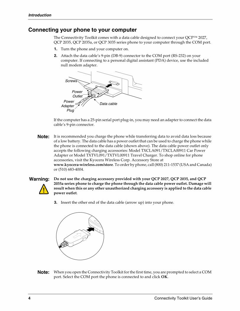
Connecting your phone to your computerThe Connectivity Toolkit comes with a data cable designed to connect your QCP™ 2027,QCP 2035, QCP 2035a, or QCP 3035 series phone to your computer through the COM port.
1. Turn the phone and your computer on.
2. Attach the data cable’s 9-pin (DB-9) connector to the COM port (RS-232) on yourcomputer. If connecting to a personal digital assistant (PDA) device, use the includednull modem adapter.
If the computer has a 25-pin serial port plug-in, you may need an adapter to connect the datacable’s 9-pin connector.
Note: It is recommended you charge the phone while transferring data to avoid data loss becauseof a low battery. The data cable has a power outlet that can be used to charge the phone whilethe phone is connected to the data cable (shown above). The data cable power outlet onlyaccepts the following charging accessories: Model TXCLA091/TXCLA00911 Car PowerAdapter or Model TXTVL091/TXTVL00911 Travel Charger. To shop online for phoneaccessories, visit the Kyocera Wireless Corp. Accessory Store atwww.kyocera-wireless.com/store. To order by phone, call (800) 211-1537 (USA and Canada)or (510) 683-4004.
Warning: Do not use the charging accessory provided with your QCP 2027, QCP 2035, and QCP2035a series phone to charge the phone through the data cable power outlet. Damage willresult when this or any other unauthorized charging accessory is applied to the data cablepower outlet.
3. Insert the other end of the data cable (arrow up) into your phone.
Note: When you open the Connectivity Toolkit for the first time, you are prompted to select a COMport. Select the COM port the phone is connected to and click OK.
Data cable
Screws
PowerAdapter
Plug
PowerOutlet

Connectivity Toolkit User’s Guide 5
Introduction
Setting up your phone as a wireless modemThe Connectivity Toolkit includes an application called QuickLink Mobile that helps youset up your phone as a wireless modem.
To install QuickLink Mobile, place the Connectivity Toolkit CD in your CD-ROM and selectInstall QuickLink Mobile.
Warning: To use QuickLink Mobile or QuickLink Fax, the Connectivity Toolkit must be closedwhile the phone is still connected. Doing so restores the phone to data mode. You may alsopower-cycle (turn off and on) the phone to return to data mode.
To view the QuickLink Mobile user’s guide, click View Documentation on the CD.
Getting helpThis user’s guide provides the basic information you need to use the Connectivity Toolkit.
The Connectivity Toolkit has online help. To access it, select Help on the menu bar inside theConnectivity Toolkit software.
If you need further assistance, contact the Kyocera Wireless Corp. Customer Care Center:� Phone: (800) 349-4478 (toll-free in the U.S.A. and Canada only) or (858) 882-1401� Email: [email protected]� Web site: www.kyocera-wireless.com� Kyocera Wireless Corp., 10300 Campus Point Drive, San Diego, CA 92121 U.S.A.

6 Connectivity Toolkit User’s Guide
Getting Started
Getting StartedConnectivity Toolkit applications include the Contact Manager, the Phone Monitor, and theRinger Downloader.
The Connectivity Toolkit also comes with wireless modem connection applications calledQuickLink Mobile 2000 and QuickLink Fax. See the Connectivity Toolkit CD to accessthese applications.
Managing multiple phonesThe Connectivity Toolkit lets you work with multiple phones by using connected phonesand phone documents.
Matching phone documents and connected phonesA phone document is always matched with a connected phone. The graphic above shows howthe Connectivity Toolkit lists a matched phone: the model number, the ESN, and phonenumber with the area code. This matched number appears in the Open Phone list (seebelow), and on any phone document you open.
To synchronize a phone document to a connected phone, the connected phone must matchthe phone document. If the Sync Current icons on the Coolbar are active (not grayed-out),then your phone document and connected phone match, and you can synchronize betweenthem.
If the sync icons are not active, click Open Phone. The Open Phone dialog appears (shownin “Working with multiple phones” on page 15). Open the phone document that matches theconnected phone.
Connectedphone
A connected phone is the phone actually connected to your computerthrough your data cable. When you connect your phone, the ConnectivityToolkit creates a phone document and names it with the phone numberof the connected phone.
Phonedocument
When you connect a phone to the Connectivity Toolkit for the first time,the contacts in the phone are automatically transferred to theConnectivity Toolkit as a phone document. Once the phone document iscreated, you can work with it any time whether the matching* phone isconnected or not.
*A match is when the phone’s and document’s model number, ESN, and phone number match. See the graphic below for anexample of how a matched phone is listed in various dialogs.
model number ESN(Electronic
Serial Number)
phone number

Connectivity Toolkit User’s Guide 7
Getting Started
Phones that work with the Connectivity ToolkitThe Connectivity Toolkit is backward compatible with several earlier model KyoceraWireless Corp. QCP phones. Not all features are available on these phones.
Earlier model phones also require different data cables. Visit www.kyocera-wireless.comfor more information.
* With some limitations.** Depending on your service provider.
Selecting a COM portWhen you open the Connectivity Toolkit for the first time, you’ll be prompted to select aCOM port (shown below).
Use the drop-down list to select the COM port your phone is connected to, then click OK.
Phone Detected windowWhenever you connect a phone that does not match the current phone document, the PhoneDetected window opens. This window asks if you want to keep working with the currentphone document or change to the newly detected phone.
Choose the newly detected phone or the current phone document. Then click OK.
Phone Type Contacts Phone Monitor Wireless Modem
QCP 3035 Yes Yes Yes
QCP 2027, 2035, and 2035a Yes Yes Yes
QCP 860™, 1960™, 2760™ Yes* No Yes
QCP 820™, 1920™ Yes* No No
QCP 2700™ Yes* No No**
QCP 800®, 1900®,Q 800®, Q 1900® Yes* No No

8 Connectivity Toolkit User’s Guide
Getting Started
If you choose to work with the newly detected phone, you’ll be prompted to save anychanges you made to the current phone document.
Note: The phone you wish to work with must be on the COM port you selected (see “Connectingyour phone to your computer” on page 4.). If it is not, please change the COM port in thePreferences dialog (see “General tab” on page 9).
Application iconsWhen you open the Connectivity Toolkit you’ll see icons on the left side of the window. Clickthe icons to open the application you want to work with.
Contact Manager icon Phone Monitor icon Ringer Downloader icon
CoolbarThe Coolbar™ helps you quickly perform tasks in the Connectivity Toolkit. The Coolbarchanges depending on the application you are in.
Contact Manager Coolbar

Connectivity Toolkit User’s Guide 9
Getting Started
Phone Monitor Coolbar Ringer Downloader Coolbar
PreferencesUse the Preferences window to change various options in the Connectivity Toolkit.
Click Edit > Preferences to open the Preferences dialog. click the tab you want to work with.Each tab is explained below.
General tab� General pane – Check the Prompt me when I close the Connectivity Toolkit checkbox if you
want to be prompted before closing the Connectivity Toolkit.� Phone Connection box – Use the drop-down list to select a COM port.� Toolbar box – Select the size of the Coolbar icons.

10 Connectivity Toolkit User’s Guide
Getting Started
Sync TabThe Sync tab allows you to set merge-sync priorities for synchronizing data between aconnected phone and a phone document, or between two phone documents.

Connectivity Toolkit User’s Guide 11
Getting Started
Sync Tab Preferences
These are the merge/sync priorities:
*Information transfer without overwriting may cause duplicate records. An example of thiswould be:
� contact in phone and contact on document have same name but differentcapitalization (John 555-1212, JOHN 555-1212)
� contact in phone and contact on document have different numbers but same name� extra spaces in same contact name
To resolve these conflicts, use one of the options listed above.
Synchronizing is explained in more detail in “Synchronizing Contacts” on page 18, andshown graphically in “Synchronizing contacts diagram” on page 19.
For syncs betweenmy phone and myphone document
Keep items in phone document and in phone:Information transfers to the connected phone withoutoverwriting existing information*.
Document has priority:Information transferred from the phone document has priorityover the connected phone.
Phone has priority:Information transferred to the connected phone has priority overthe phone document.
For syncsbetween two
phone documents
Keep items in both phone documents:Information transfers between phone documents withoutoverwriting any information.
Current document has priority:Information transferred between the current phone documenthas priority over the selected phone document.
Selected document has priority:Information transferred between the selected phone documenthas priority over the current phone document.

12 Connectivity Toolkit User’s Guide
Contact Manager
Contact ManagerThe Contact Manager helps you manage your phone number information (contacts) fromyour desktop or laptop computer. This section describes how to use the Contact Manager.
Opening Contact ManagerClick the Contact Manager icon to open the Contact Manager application (if it is notalready open – the Contact Manager window opens by default).
The Contact windowThe Contact window has two panes. The left pane shows the contact list. The right panedisplays the details for a selected contact. The right column of the left pane is left blank onpurpose.
Contact listThe Contact list displays your contacts by name. Contacts are viewed by specific groups.
Click View > Contact Type to select a view. The groups include:� Business – Displays all business contacts� Personal – Displays all personal contacts� Default – Displays contacts labeled as default� All – Displays all contacts

Connectivity Toolkit User’s Guide 13
Contact Manager
Contact detailsThe details of a contact are displayed in the pane to the right of the contact list. They includename and address, phone numbers, Internet address, and email address.
The contact may also include the following information:� Primary Number – Indicates that the phone number is the primary number. When the
contact is synchronized to the phone, this number is dialed if the contact is selected.� Speed dial position – Indicates that this number has a speed dial shortcut.� Secret – Indicates the number is secret.
Contact Manager menus
You will find the menu structure for the Contact Manager listing all menus and sub-menusin the online help.
Right-click shortcut menu
The Contact Manager has several shortcuts allowing you to quickly modify contacts byright-clicking them. Shortcuts and their functions are listed in the online help.
Creating/editing contactsUse the New (Edit) Contact window to create new contacts or change information in existingcontacts.
To create a new contact, select File > New Contact or click a blank space in the Contact list.
To edit an existing contact, click the existing contact in the Contact list.
The New (Edit) Contact window opens. The window has three information tabs, explainedbelow.
Name and Number tabFill in the applicable areas in the Name and Number tab.
1. Put a check in the This contact should be synced with the phone checkbox if you want thiscontact to be synchronized.
2. Fill in the Name and Address fields as needed.

14 Connectivity Toolkit User’s Guide
Contact Manager
3. Use the Contact Type drop down menu to assign the contact a particular group.– Contact groups that can be assigned include Default, Personal, and Business. When
the contact is tagged with a group name, it appears in the Contact list when that groupis viewed.
4. Enter phone numbers in the phone number fields. Use the drop-down list on the left toclassify the type of phone number.
5. Click the Details button next to each number to set specific attributes for that number.
Setting phone number details is explained in the following section. The Internet and Notestabs are explained on page 15.
Setting phone number details
The Phone Number Details window sets attributes for phone numbers within a specificcontact.
1. Click the Details button next to the phone number to set phone number attributes. ThePhone Number Details window opens.
2. Click the tab of the number you want to change.
3. Select the attributes for the number. Each is explained below:� Main Properties
– Phone Number: Shows the phone number. The number can be changed here.– Type: Use the drop-down list to select a type for each phone number. Types
include Home, Work, Mobile, Pager, and Fax.� Details
– Speed Dial Position: Check this checkbox and use the drop-down list to select aspeed dial position for this phone number. You may only select available speeddial numbers.
– Primary Number: Check this checkbox to indicate that the phone number is aprimary number. “Primary Number” is displayed in the contact.
� Secrecy: Select “Secret” if you want the number to be secret. The default is “NotSecret.”
4. Click any of the other tabs to make changes to other phone numbers.
5. Click OK to exit the Phone Number Details window.

Connectivity Toolkit User’s Guide 15
Contact Manager
Internet tabClick the Internet tab and fill in the appropriate information in the fields for Internetaddresses and email addresses. You are provided with two fields for each type of address.
Notes tabClick the Notes tab and enter any notes you may have for this contact. The Notes field holds250 characters. Notes do not appear in the contact window, but are synchronized to thephone.
Working with multiple phonesThe Connectivity Toolkit allows you to manage multiple phones by using phone documents.Each phone document is matched with a connected phone. For more information, see“Synchronizing contacts diagram” on page 19.
Opening a phone document
1. To open a phone document, click the Open Phone icon or select
2. File > Open... The Open Phone dialog opens.
3. Use the drop-down list to select a phone document. Phone documents are named withtheir associated or matched phone numbers (see above).The Connectivity Toolkit remembers every phone you ever connected to it.
4. Click OK. The contact list for the phone document opens.
By using phone documents, it is possible to synchronize the contacts of one phone intoanother phone, or into several phones. This is explained in more detail in “Synchronizingcontacts diagram” on page 19.

16 Connectivity Toolkit User’s Guide
Contact Manager
Working with area codesYou may change area codes for phone numbers in a variety of ways:� Change one area code for another.� Add area codes to selected contacts.� Remove area codes from selected or all contacts.
These methods are described below.
Changing area codes
1. Select the contact(s) that need an area code change.
2. Right-click the contact, select Area Code, and select Change. The Change Area Codedialog opens.
3. Enter the old area code and the new area code in the provided text boxes.
4. Click OK.
Adding an area code
1. Select the contact(s) that needs a new area code.
2. Right-click the contacts, select Area Code, and select Add. The Add Area Code windowopens.
3. Enter the new area code.
4. Click OK.

Connectivity Toolkit User’s Guide 17
Contact Manager
Removing an area code
1. Select the contact(s) that need an area code removed.
2. Right-click the contacts, select Area Code, then select Remove. The Remove Area Codedialog opens.
3. Enter the area code you want to remove.
4. Click OK.
Locking/unlocking secret numbersYou can lock or unlock all the secret phone numbers in a phone document at once. The lockcode used to unlock the secret number in a phone document is the same lock code used forthe phone that created the phone document. The default lock code for QCP 2027, 2035, 2035a,and 3035 phones is usually the last four digits of your phone number. See your phone’sdocumentation or ask your service provider if you’re not sure.
Unlocking secret numbers
1. Select Tools > Unlock. The Unlock window opens.
2. Enter the phone’s lock code.
3. Click OK.
All the secret items for that phone document are now unlocked.
Locking secret numbers
To lock secret phone numbers in a phone document, select Tools > Lock Secret…
All secret phone numbers for the active phone document are now locked.

18 Connectivity Toolkit User’s Guide
Synchronizing Contacts
Synchronizing Contacts
Synchronizing is a way of transferring contacts and other information between theConnectivity Toolkit and your phone.
There are two types of synchronizing:
See “Synchronizing contacts diagram” on page 19 for a graphical representation of synchronizing.
Synchronizing a phone document to a connected phoneTo synchronize a phone document with a connected phone, the phone document and theconnected phone must match each other. (A match is when the phone’s and document’smodel number, ESN, and phone number match.) If the Sync icons on the Coolbar are active(not grayed-out), the connected phone matches the phone document and synchronizing ispossible.
Active Sync icons
If the sync icons are not active, use the Open Phone window (see page 15 for information onthe Open Phone window) to open the matching phone document.
Sync Contacts with phone1. Select a phone document. You may already have one open. If not, see “Working with
multiple phones” on page 15.
2. Click the Sync Contacts with phone icon on the Coolbar or select Sync > Contactswith phone. The Sync with phone dialog opens.
Synchronizing a phonedocument and a
connected phone
Contacts with Phone:This option synchronizes the current phone document with theconnected phone.
Synchronizing twophone documents
Contacts with phone document:This option synchronizes the current phone document with theselected phone document.

Connectivity Toolkit User’s Guide 19
Synchronizing Contacts
3. Select the synchronization option you wish. See “Options for synchronizing a phonedocument to a connected phone” in the next section for more information.
4. Click OK. The contact information is synchronized to the phone.
Options for synchronizing a phone document to a connected phone
These options tell the Connectivity Toolkit what to do if duplicate data appears whilesynchronizing.� Overwrite phone – Information goes from the phone document to the connected phone.
Contacts in the connected phone are overwritten.� Overwrite phone document – Information goes from the phone document to the
connected phone. Contacts in the phone document are overwritten.� Merge phone document and phone – (default setting) Contacts from the phone
document and the connected phone merge together. No information is overwritten.
If you select the merge option, the following options become available.– And overwrite phone – Merges information between phone documents and
connected phones and overwrites the connected phone.– And overwrite phone document – Merges information between phone documents
and connected phones and overwrites the phone document.– And overwrite both – (default setting) Merges information between phone
documents and connected phones, and overwrites both.For more information see “Sync Tab Preferences” on page 11.
Synchronizing contacts diagramThis diagram describes the concept of synchronizing contacts between phones graphically.Phone 1 (P1 below) can only be synchronized with Document 1 (D1). Document 1, however,may be synchronized with Document 2 (D2). Phone 2 (P2) can then be synchronized withPhone 1 (P1) by synchronizing Document 1 and Document 2. You cannot synchronize directlybetween phones, nor directly between Document 1 and Phone 2 or Phone 1 and Document 2.You must use phone documents to synchronize between phones.

20 Connectivity Toolkit User’s Guide
Synchronizing Contacts
So in order to place the contacts of Phone 1 into Phone 2, follow these steps:
1. Create Document 1. Perform “Sync Contacts with phone” on page 18 with Phone 1.
2. Create Document 2. Perform “Sync Contacts with phone” on page 18 with Phone 2.Leave Phone 2 connected.
3. Synchronize Document 1’s contacts into Document 2’s contacts by performing “Syncingtwo phone documents” on page 20.
4. Perform another “Sync Contacts with phone” on page 18 with Phone 2. The contents ofPhone 1 are now in Phone 2.
By repeating these steps with other phones, it is possible to place one set of contacts inmultiple phones (see “Working with multiple phones” on page 15).
Syncing two phone documentsThis section explains how to synchronize one phone document to another phone document.
1. Select a phone document. You may already have one open. If not, see “Working withmultiple phones” on page 15.
2. Select Sync > Contacts with Document... The Sync with phone document dialog opens.
3. Use the drop-down list to select the target phone document.
4. Select the synchronization option you want. See “Options for synchronizing two phonedocuments,” in the next section.
5. Click OK.
The contacts are sent to the target phone document.
Options for synchronizing two phone documents
The synchronization options in the Sync to phone document dialog offer various ways tosynchronize one phone document to another. The options tell the Connectivity Toolkit whatto do if a conflict occurs while synchronizing.� Overwrite selected document – Information goes from the current phone document to
the selected phone. Contacts in the selected phone document are overwritten.� Overwrite this document – Information goes from the current phone document to the
selected phone. Contacts in the current phone document are overwritten.� Merge both documents – (default setting) Contacts from the current phone document
and the select phone document merge together. No information is overwritten.

Connectivity Toolkit User’s Guide 21
Synchronizing Contacts
If you select the merge option, the following options become available.– And overwrite selected document – Merges both phone documents and overwrites
the selected phone document.– And overwrite current document – Merges both phone documents and overwrites
the current phone document.– And overwrite both documents – (default setting) Merges both phone documents
and overwrites both phone documents.For more information see “Sync Tab Preferences” on page 11.

22 Connectivity Toolkit User’s Guide
Importing Data
Importing DataThe Connectivity Toolkit allows you to import contact lists and calendar information fromyour computer or laptop into your Kyocera Wireless phone.
Importing contact informationThe Import Contacts... menu allows you to import contact information from otherapplications if the information is saved as a CSV file. CSV files are comma- or tab-separatedfields of information and can be created in most text editors.
To import contacts, follow the steps below.
1. Select Tools > Import Contacts… The Import Contact dialog opens.
2. Check the The fields are enclosed within quotes box if the information you are importinguses quotes.� Some applications use quote marks to indicate when a field begins and ends.
3. Select Comma or Tab from the drop-down list to indicate how the information isseparated. Each field in a CSV file is separated by commas or tabs. The comma or tab tellsthe importer where a field of information begins and ends.
4. Use the data field drop-down lists to select where the imported information should goin the Contact Manager. The first data field represents the first field of information inyour CSV file; the second data field represents the second field; and so on.� Use the drop-down lists in each field to tell the importer where the information
should go. For example, if Last Name is selected for the first data field, thatinformation will go in the Name field in the Contact window when imported. IfHome Phone is selected in the first field, the information would be imported to theHome Phone field.
� To skip a field, select Don’t Care.� To add additional fields, change the last field from End to the category you want.
This opens a new field. You may have up to 15 fields.As you add and remove fields, you will notice that the Import Contacts dialog addsand removes drop-down fields as you need. You can remove several fields at onceby selecting End from one of your earlier selected fields.
5. Click OK. The CSV File dialog opens.
6. Select the CSV file you want to import and click Open. The information is imported intothe contact list.

Connectivity Toolkit User’s Guide 23
Importing Data
Importing calendar informationThe Import Calendar... menu allows you to import scheduler information to your QCP 3035phone from your calendar or scheduling program. The Connectivity Kit supports filesexported from� Meeting Maker� by On Technology� and� Outlook� 97, 98, and 2000 by Microsoft�
Files must be exported as .sdf files (simple delimited) or .csv files (comma or space delimited)in order to be imported into your phone.
Follow these steps to import calendar information into your phone.
1. Export your calendar from your scheduling program.– For Meeting Maker, this means use the CasioLink™ format (as an .sdf file)– For Outlook, this means use the .csv formatConsult your scheduling program’s user’s guide or help files if you need help doing this.
2. Select Tools > Import Calendar...
3. The Import Calendar dialog appears. Select the type of calendar information you wishto import (Meeting Maker, Outlook 98, Outlook 2000).
4. Click Next. Another dialog appears asking you to open the .csv or .sdf file.
5. Select Open File. A standard Windows file dialog opens. Navigate to the file you wishto import and press Open.
6. The file is selected and you return to the Import Calendar dialog. To accept your choiceand continue, press Finish.
7. That’s it! Your schedule is now in your phone, ready for use.
You may press Back at any time to move back one dialog or Cancel to stop importing andreturn to the Connectivity Toolkit.
Note: Your phone must have digital service in order to display your schedule.

24 Connectivity Toolkit User’s Guide
Phone Monitor
Phone MonitorThe Phone Monitor shows your phone’s display on your computer screen and lets youcontrol phone functions using your computer’s keyboard. Change settings, edit contacts, getmessages, dial numbers, even play games – all from your desktop or laptop computer.
Phone Monitor keymapA picture with the QCP 2027, 2035, 2035a, or 3035 phone appears on the right side of thePhone Monitor window showing the keyboard keys that control the phone’s functions. Youmay also control the phone’s functions using the keys on the phone itself.
Phone Monitor displayThe Phone Monitor display is on the left side of the Phone Monitor window. It shows thecurrent screen of the connected phone.� If no phone is connected, the message “No Phone” is displayed.� If an unsupported phone is connected, the message “Unsupported” appears.
Using Phone Monitor1. Connect a QCP 2027, 2035, 2035a, or 3035 phone to the Connectivity Toolkit. If your
phone is already connected, go to step 3.
2. Click the I wish to work with the new phone... option in the Detected Phone dialog.
3. Click the Phone Monitor application icon to open Phone Monitor.
4. The display of the connected phone appears in the Phone Monitor window.

Connectivity Toolkit User’s Guide 25
Phone Monitor
5. Use the keys on the computer keyboard shown in the phone illustration to control thephone’s functions. You may also use the phone keys to control phone functions.
Adjusting Phone Monitor refresh rateThe Phone Monitor refresh rate may be adjusted to fit your needs:
1. Select View > Monitor Refresh Rate…
2. Select the refresh rate you want.
Adjusting Phone Monitor window sizeThe Phone Monitor display size can be adjusted to fit your needs:
1. Select View > Monitor Size…
2. Choose the view you want. The Phone Monitor window opens to that size.

26 Connectivity Toolkit User’s Guide
Ringer Downloader
Ringer DownloaderThe Ringer Downloader application allows the transfer of user-defined ringers into yourQCP 3035 series phone. Ringer files, a cool way to customize your Kyocera Wireless Corp.phone, are available from our web site:http://www.kyocera-wireless.com/support/how_to/qcp3035_ringer.htm.
Click the application icon , to open the Ringer Downloader, shown below.
The Ringers windowThe Contact window has two panes. The left pane shows the ringers list. The right panedisplays the details for a selected ringer. The right column of the left pane is left blank onpurpose.
Downloading ringersTo download ringers into your phone:
1. Select a phone document. You may already have one open. If not, see “Working withmultiple phones” on page 15.
2. Click the Import ringers button in the Coolbar or select File > Import ringers....
3. A standard Open File dialog appears. Find the directory that contains the ringer filesyou wish to download into your phone.– Ringer files are of the .kws type and must be obtained from the website listed above.
4. Select the file(s) you wish and click OK.– A maximum of 15 user-defined ringers are allowed.
5. Click the Sync Ringers button in the Coolbar or select Sync > Ringers with Phone...The Sync with Phone dialog appears. Follow the same procedure as synchronizingcontacts with your phone (see “Sync Contacts with phone” on page 18).
6. That’s it! The ringers are now in your phone, ready for use.
Your new ringers are now on the ringers list on the left pane of the Ringers applicationwindow.

Connectivity Toolkit User’s Guide 27
AT Command Reference
AT Command ReferenceThe modem functions in the phone are controlled using the same industry standard ATcommands that are used to control landline modems. A knowledge of these commands isnot required by most users of the phone, but they are provided here for reference.
The parameters set by the various AT commands in this appendix are remembered by thephone, and are transmitted to the modem at the carrier's site each time you make a call. Inthis way, your settings continue to be used until you power down the phone. The settingsare lost on power-down.
It also gives you automatic support of all AT commands that are unknown to the phone butare supported by your cellular carrier. Since the carrier may charge you for the air time usedfor this connection, the phone’s autoconnect ability is disabled by default. (Use the AT+CXTcommand to change this behavior.)
The phone has two operational states:� Command state� Online state
Initially, it is in the Command state where the phone accepts the industry-standard ATcommands. When instructed to dial out or answer a data call, the phone is in the online state.
Modes of OperationAsynchronous mode - used to transfer information between two computers.
Facsimile (fax) mode - used to transfer information between two Group 3 fax machines withdigital interfaces (or computer applications that can emulate these machines).
SpeedsThe serial port of the phone defaults to 19200 bps at power-up. The laptop serial port musttherefore be configured at 19200 baud.
The band rate can be changed via the AT+IPR command, but it will return to 19200 after apower cycle.
Command Line SyntaxA command line consists of the Attention code, followed by one or more commands,followed by the end of line code. The Attention code is the character pair "AT" or "at."
By default, the end of line character is the ASCII CR character (decimal 13), unless it ischanged by the S3 command (see the S-Registers Table). Spaces are ignored but may beincluded between commands, if desired.
The basic and S-register commands may follow each other on the command line without anyseparating delimiters. The extended format commands (those beginning with a "+"character) must be terminated by a ";" if they are followed by another command on the sameline. A";" is not required after the last command on the line.
Commands may be edited by using the backspace character. The backspace deletes the lastcharacter in the command line. The backspace will not delete the AT at the beginning of theline.
The A/ command repeats the last command line received by the modem. The A/ is used inplace of the AT and is not followed by a carriage return.

28 Connectivity Toolkit User’s Guide
AT Command Reference
Basic Sets of CommandsThis section lists some basic commands for you to use with your phone.
Types of CommandsThere are nine types of commands:� Basic AT parameters� S-registers� Basic Action commands� Extended Configuration commands� Fax parameters� Fax Action commands� Cellular CDMA commands� Cellular AT commands� Cellular Identification commands
Result CodesWhen in the command mode, eight possible result codes may be returned.
The digit code is returned when the verbose mode is OFF; the word code is returned whenthe verbose mode is ON. See the 'V' command in the Basic AT Parameters Table.
Extended result codes may also be returned. Extended result codes are listed in the followingtable.
Basic AT Commands
Command Description
ATDT5553232 connects to the number 555-3232. There will be a delay of up to 20 sec-onds before the phone actually connects. Successful connection is identi-fied by a connect message on the computer. Your cellular carrier maysupport the *3282 prefix for modem pools. If they do, ask them how to useit in order to receive better AMPS data performance.
ATH hangs up the phone. There will be a delay before this happens.
ATSO=3 sets auto answer 15 seconds after first ring.
AT+CXT sets whether the phone will originate a call upon reception of an unknownAT command. AT+CXT=O disables the unknown AT command origina-tion.
Result Codes Table
Digit Verbose Description
0 OK Command executed without errors.
1 CONNECT Connected to remote modem
2 RING Incoming Call.
3 NO CARRIER Carrier from remote modem lost or neverpresent.

Connectivity Toolkit User’s Guide 29
AT Command Reference
Basic AT ParametersThese commands control the basic configuration of the modem. The parameters can only beread back by the &V command when in command state. The following table shows thecommand format.
4 ERROR Error in the command line.
6 NO DIALTONE No dial tone detected within time out period.
7 BUSY Busy signal detected.
8 NOANSWER Five seconds of silence not detected after ringback when @ dial modifier is used.
Result Codes Table
Digit Verbose Description
Basic AT Parameters Table
Parameter Description
E0 Do not echo commands in command state or online command state.
E1 Echo commands in command state or online command state.
L0 Low speaker volume.
L1 Low speaker volume.
L2 Med speaker volume.
L3 High speaker volume.
M0 Speaker off.
M1 Speaker on until carrier reported (support of this feature is optional).
M2 Speaker on (support of this feature is optional).
Q0 Return result codes.
Q1 Do not return result codes.
V0 Display result codes as numbers.
V1 Display result codes as words.
X1 Enable additional result code CONNECT <rate>.Disable dial tone and busy detection.1
X2 Enable additional result codes CONNECT <rate> and NO DIALTONE.Disable busy detection. Enable dial tone detection.1
X3 Enable additional result codes CONNECT <rate> and BUSY. Enablebusy detection. Disable dial tone detection.1

30 Connectivity Toolkit User’s Guide
AT Command Reference
* Factory Default Settings
S-RegistersThe value of an S-register may be set by using the syntax,
Sn=xxx
where n is the register number and xxx is a decimal value.
For instance, to set the register SO to 3, the command SO=3 would be used. r1b read registerSO, the command SO? is used. The following table describes the S-registers.
X4 Enable additional result codes CONNECT <rate>, BUSY and NODIALTONE. Enable busy and dial tone detection.1
Z0 Reset to default configuration.
&C0 Circuit 109 (CF) always ON.
&C1 Circuit 109 (CF) ON in accordance with the specified service.
&C2 Circuit 109 (CF) always on except wink on channel disconnect
&D0 Ignore circuit 108/2 (CD).
&D1 Enter online command state following ON-to-OFF transition of circuit108/2.
&D2 Enter command state following On to Off transition of circuit 108/2.
T Select tone dialing.
P Select pulse dialing.
&F0 Effect is implementation dependent.
&FO Set to default configuration
&V Dump configuration parameters
Basic AT Parameters Table
Parameter Description
S-Registers Table
Register Value Description
S0 0[1 to255]
Disable automatic answering.[Enable automatic answering after(Value - 1) ? 6 seconds.]
S3 13 Carriage Return character.
S4 10 Line Feed character.
S5 8 Backspace character.

Connectivity Toolkit User’s Guide 31
AT Command Reference
Basic Action CommandsThe following table describes the Basic Action commands.
S6 2 to 102
Pause before blind dialing.
S7 1 to 255[50]
Number of seconds to establishend-to-end data connection.
S8 0 to 2552
Number of seconds to pause when “,” is encounteredin dial string.
[S9] 0 to 2556
Carrier detect threshold in increments of 0.1 seconds.
S10 1 to 254[14]
Number of tenths of a second from carrier loss to dis-connect.
[255] [Disable carrier detect.]
[S11] 50-25595
DTMF tone duration and spacing in milliseconds.
S-Registers Table
Register Value Description
Basic Action Commands Table
Command Description
A Go off hook. Answer any incom-ing call
D<dial string> Dial. The dial string may containthe following characters:
Digits 0 to 9, *, #, A, B, C, and D.
The dial string may contain thefollowing dial modifiers:
T Tone dialing
P Pulse dialing
, Pause during dialing
W Wait for dial tone
@ Wait for quiet answer
! Hook flash
$ Wait for billing tone (forcredit-card calls)

32 Connectivity Toolkit User’s Guide
AT Command Reference
Extended CommandsThe extended commands use the extended syntax. To set a value using an extendedcommand, use the WRITE command:
+CMD=xxx
where CMD is the command, and xxx is the value.
Some extended commands take more than one value. For example, the WRITE command fortwo values becomes
+CMD=xxx,yyy
Some extended commands take character strings as values, instead of numbers. In that case,the syntax is
+CMD="character string"
Note that while spaces are ignored everywhere else, spaces are significant inside thequotation marks.
To read back a value, use the READ command:
+CMD?
To determine if a particular command is supported, along with the range of values itsupports, use the TEST command:
+CMD=?
An extended command must be terminated with a semicolon if another command follows iton a single command line.
The following table describes the extended AT configuration commands.
; After dialing, the phoneremains in commandstate
HO Disconnect and return to com-mand state.
00 Return to online data state from
Basic Action Commands Table
Command Description
Extended AT Configuration Commands Table
Command Description
+DR Data Compression Reporting. This extended-format numericparameter controls whether or not the extended-format “+DR:” inter-mediate result code is transmitted from the IWF over the Um inter-face.
+DS Data Compression. This extended-format compound parameter con-trols the V.42bis data compression function on the PSTN link if pro-vided in the IWF.

Connectivity Toolkit User’s Guide 33
AT Command Reference
+EB Break Handling in Error Control Operation. This extended-formatcompound parameter is used to control the manner of V.42 operationon the PSTN link (if present in the IWF).
+EFCS This extended-format numeric parameter controls the use of the32-bit frame check sequence option in V.42 on the PSTN link (ifpresent in the IWF).
+ER Error Control Reporting. This extended-format numeric parametercontrols whether or not the extended-format “+ER:” intermediateresult code is transmitted from the IWF over the Um interface.
+ES Error Control Selection. This extended-format compound parameteris used to control the manner of operation of the V.42 protocol on thePSTN link (if present in the IWF).
+ESR This extended-format numeric parameter controls the use of theselective repeat (SREJ) option in V.42 on the PSTN link (if present inthe IWF).
+ETBM This extended-format compound parameter controls the handling ofdata remaining in IWF buffers upon service termination.
+GCAP This extended-format command causes the MT2 to transmit one ormore lines of information text in a specific format. The content is a listof additional capabilities command +<name>s, which is intended topermit the user of the MT2 to identify the minimum capabilities of theMT2.An MT2 conforming to this standard shall include the following items,as a minimum, in the result code for the +GCAP command+CIS707, +MS, +ES, +DS, +FCLASS
+GMI This command causes the MT2 to transmit one or more lines of infor-mation text, determined by the manufacturer, which is intended topermit the user of the MT2 to identify the manufacturer. Typically, thetext will consist of a single line containing the name of the manufac-turer, but manufacturers may choose to provide more information ifdesired (e.g., address, telephone number for customer service, etc.)
+GMM This command causes the MT2 to transmit one or more lines of infor-mation text, determined by the manufacturer, which is intended topermit the user of the MT2 to identify the specific model of thedevice. Typically, the text will consist of a single line containing thename of the product, but manufacturers may choose to provide anyinformation desired.
+GMR This command causes the MT2 to transmit one or more lines of infor-mation text, determined by the manufacturer, which is intended topermit the user of the MT2 to identify the version, revision level ordate, or other pertinent information of the device. Typically, the textwill consist of a single line containing the version of the product, butmanufacturers may choose to provide any information desired.
Extended AT Configuration Commands Table
Command Description

34 Connectivity Toolkit User’s Guide
AT Command Reference
+GOI This command causes the MT2 to transmit one or more lines of infor-mation text, determined by the manufacturer, which is intended topermit the user of the MT2 to identify the device, based on the ISOsystem for registering unique object identifiers. Typically, the text willconsist of a single line containing numeric strings delimited by periodcharacters.
+GSN This command causes the MT2 to transmit one or more lines of infor-mation text, determined by the manufacturer, which is intended topermit the user of the MT2 to identify the individual device. Typically,the text will consist of a single line containing a manufacturer deter-mined alpha-numeric string, but manufacturers may choose to pro-vide any information desired.
+ICF TE2-MT2 Character Framing. This extended-format compoundparameter is used to determine the local serial port start-stop (asyn-chronous) character framing that the MT2 shall use while acceptingTE2 commands and while transmitting information text and resultcodes to the TE2, if this is not automatically determined (see +IPR).
+IFC TE2-MT2 Local Flow Control. This extended-format compoundparameter is used to control the operation of local flow controlbetween the TE2 and MT2 [1].
+ILRR TE2-MT2 Local Rate Reporting. This extended-format numericparameter controls whether or not the extended-format +ILRR:<rate>information text is transmitted from the MT2 to the TE2.
+IPR Fixed Rm Rate. This numeric extended-format parameter specifiesthe data rate at which the MT2 will accept commands, in addition to1200 bit/s or 9600 bit/s (as required in EIA/TIA-602). It may be usedto select operation at rates at which the MT2 is not capable of auto-matically detecting the data rate being used by the TE2.
+MA Modulation Automode Control. This extended-format compoundparameter is a list of modulations that the base station may use toconnect with the remote DCE in Automode operation, for answeringor originating data calls, as additional alternatives to the modulationspecified in the +MS command.
+MR Modulation Reporting Control. This extended-format numeric param-eter controls whether or not the extended-format +MCR:<carrier>and +MRR:<rate> intermediate result codes are transmitted from theIWF to the mobile station.
+MS Modulation Selection. This extended-format compound parameter isused to control the manner of operation of the modulation capabilitiesin the IWF.
+MV18R V.18 Reporting Control. This extended-format numeric parametercontrols whether or not the extended-format “+MV18R:” result codeis transmitted from the IWF to the mobile station.
Extended AT Configuration Commands Table
Command Description

Connectivity Toolkit User’s Guide 35
AT Command Reference
*Factory Default Settings
Fax ParametersThe Fax parameters follow the same syntax rules as the extended commands, except that thenumeric values are in hexadecimal, instead of decimal. The following table describes the Faxparameters.
These commands are used between Fax applications and the modem and are listed forreference only.
+MV18S V.18 Selection. This extended-format compound parameter is usedto control the manner of operation of the V.18 capabilities (if presentin the IWF).
Extended AT Configuration Commands Table
Command Description
Fax Parameters Table
Command Description
+FAA Adaptive-answer parameter. See +FCLASS.
+FAP Addressing and Polling capabilities parameter
+FBO Phase-C data-bit-order parameter
+FBS Buffer size. Read-only parameter.
+FBU HDLC-frame-reporting parameter
+FCC DCE-capabilities parametersVC - Vertical-resolution subparameter[BR] - Bit-rate subparameter
• 2400 bits/s• 4800 bits/s• 7200 bits/s• 9600 bits/s
WD - Page-width subparameter[LN] - Page-length subparameter[DF] - Data-compression-format subparameter[EC] - Error-correction subparameterBF - Binary-file-transfer subparameterST - Scan-time-per-line subparameter
[+FCLASS] Service-class selection parameter• Class-0• [Class-1 support unavailable]• Class-2.0 fax service (EIA/TIA-592)
+FCQ Copy-quality-checking parameter
[+FCR] Capability-to-receive parameter
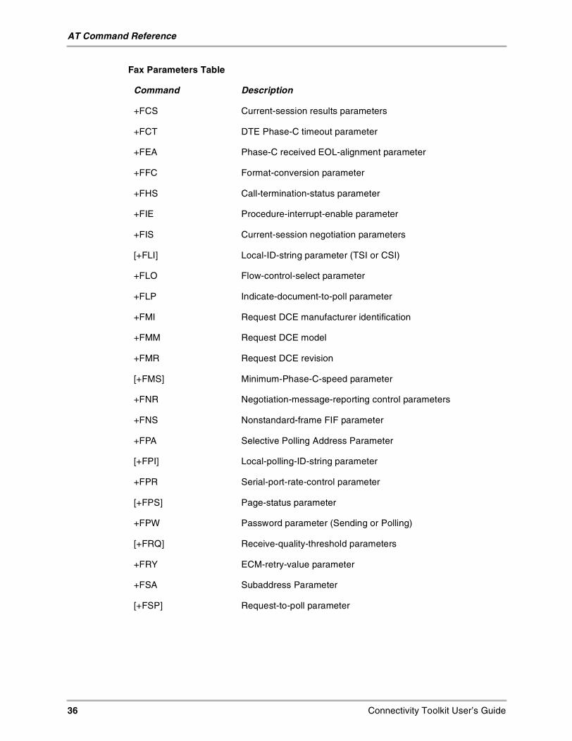
36 Connectivity Toolkit User’s Guide
AT Command Reference
+FCS Current-session results parameters
+FCT DTE Phase-C timeout parameter
+FEA Phase-C received EOL-alignment parameter
+FFC Format-conversion parameter
+FHS Call-termination-status parameter
+FIE Procedure-interrupt-enable parameter
+FIS Current-session negotiation parameters
[+FLI] Local-ID-string parameter (TSI or CSI)
+FLO Flow-control-select parameter
+FLP Indicate-document-to-poll parameter
+FMI Request DCE manufacturer identification
+FMM Request DCE model
+FMR Request DCE revision
[+FMS] Minimum-Phase-C-speed parameter
+FNR Negotiation-message-reporting control parameters
+FNS Nonstandard-frame FIF parameter
+FPA Selective Polling Address Parameter
[+FPI] Local-polling-ID-string parameter
+FPR Serial-port-rate-control parameter
[+FPS] Page-status parameter
+FPW Password parameter (Sending or Polling)
[+FRQ] Receive-quality-threshold parameters
+FRY ECM-retry-value parameter
+FSA Subaddress Parameter
[+FSP] Request-to-poll parameter
Fax Parameters Table
Command Description

Connectivity Toolkit User’s Guide 37
AT Command Reference
Fax Action CommandsThese commands do not have arguments. The following table describes the Fax Actioncommands.
Cellular CDMA CommandsThe cellular CDMA commands use the same syntax as the other extended commands.Numeric values are decimal. The following table describes the Cellular CDMA commands.
Fax Action Commands Table
Command Description
+FDR Receive Phase-C data.
+FDT Transmit Phase-C data.
+FIP Initialize facsimile parameters.
+FKS Terminate session.
CDMA AT Parameter Commands Table
Command Description
+CXT=<value> Cellular Extension.0 Do not pass unrecognized commands to the IWF.1 When detecting an unrecognized AT command, open trans-port layer connection and pass unrecognized command to theIWF.
+CFG=“<string>” Configuration String.The string (up to and including the termination character) will bestored by the MT2 and sent to the base station prior to dialing.Each transmission of an AT+CFG command from the TE2replaces the contents of the previous string. The string may beup to 248 characters.
+CAD? Query Analog or Digital Service.Returns:0 if no service is available1 if CDMA Digital service available2 if TDMA Digital service available3 if Analog service is available(values 4-255 reserved)
+CDR Um Interface Data Compression Reporting.This extended-format numeric parameter controls whether or notthe extended-format “+CDR:” intermediate result code is trans-mitted by the MT2. The result code is the same as for theTIA/EIA/IS-131 +DR: result code.

38 Connectivity Toolkit User’s Guide
AT Command Reference
+CDS Um Interface Data Compression. This extended-format com-pound parameter controls the V.42bis data compression functionon the Um interface. The command format is the same as for theTIA/EIA/IS-131 +DS command.
+CRM=<value> Set Rm interface protocol.0 Asynchronous Data or Fax1 Packet data service,Relay Layer Rm interface2 Packet data service,Network Layer Rm interface, PPP3 Packet data service,Network Layer Rm interface, SLIP4 STU-III Service5-127 Reserved for future use128-255 Reserved for manufacturerspecific useNote: The default value for the +CRM parameter shall be 0 if thisvalue is supported by the MT2. If 0 is not supported, the default+CRM value shall be manufacturer specific.
+CBC? Battery Charge.Read-only. Returns <BCS>,<BCL>BCS:0 MT2 powered by battery, BCL = status1 MT2 connected to external power2 Battery status not available3 Recognized power fault. Calls inhibited.
BCL:0-100 Remaining battery capacity is 0-100%.
+CDS Um Interface Data Compression. This extended-format com-pound parameter controls the V.42bis data compression functionon the Um interface. The command format is the same as for theTIA/EIA/IS-131 +DS command.
CDMA AT Parameter Commands Table
Command Description

Connectivity Toolkit User’s Guide 39
AT Command Reference
+CRM=<value> Set Rm interface protocol.0 Asynchronous Data or Fax1 Packet data service,Relay Layer Rm interface2 Packet data service,Network Layer Rm interface, PPP3 Packet data service,Network Layer Rm interface, SLIP4 STU-III Service5-127 Reserved for future use128-255 Reserved for manufacturerspecific useNote: The default value for the +CRM parameter shall be 0 if thisvalue is supported by the MT2. If 0 is not supported, the default+CRM value shall be manufacturer specific.
+CBC? Battery Charge.Read-only. Returns <BCS>,<BCL>BCS:0 MT2 powered by battery, BCL = status1 MT2 connected to external power2 Battery status not available3 Recognized power fault. Calls inhibited.
BCL:0-100 Remaining battery capacity is 0-100%.
+CQD=<value> Command State Inactivity Timer (see 3.9.1.3).0 Ignored1-255 Release call after 5x<value> seconds have elapsed with-out activity. The default <value> shall be 10, corresponding to50 seconds.
+CRC=<value> Cellular Result Codes (see Table 7.4.2-1).0 Disable Cellular Result Codes1 Enable Cellular Result Codes
+CMIP? Mobile Station IP Address.Read-only. Returns the mobile station’s temporary IP address.
+CBIP? Base Station IP Address.Read-only. Returns the base station’s IP address.
CDMA AT Parameter Commands Table
Command Description

40 Connectivity Toolkit User’s Guide
AT Command Reference
*Factory Default Settings
+CSS? Serving System.Read-only. Returns <AB>,<SID>AB:A The mobile station is registered with anA-band system.B The mobile station is registered with aB-band system.Z The mobile station is not registered.SID:0-16383 The mobile station is registered with the system indi-cated.99999 The mobile station is not registered.
+CSQ? Query Received Signal Quality.Returns the Signal Quality Measure <SQM> and the Frame ErrorRate <FER> as follows:Signal Quality Measure <SQM>0-31 Signal Quality Measurement(see Note 1).99 SQM is not known or is not detectable.All other values are reserved.Frame Error Rate <FER>0<0.01%10.01% to less than 0.1%20.1% to less than 0.5%30.5% to less than 1.0%41.0% to less than 2.0%52.0% to less than 4.0%64.0% to less than 8.0%7?8.0%99 <FER> is not known or is not detectable.All other values are reserved.
+CFC=<value> Um Interface Fax Compression.0 No compression.1 V.42bis compression with parameters as set by the +CDS com-mand.2 Modified Read compression.
Note 1. The exact meaning of the Signal Quality Measure shall be manufacturer defined. The lowest qualityreported by SQM shall be defined as value 00.The highest quality reported by SQM shall be defined as value 31.
CDMA AT Parameter Commands Table
Command Description

Connectivity Toolkit User’s Guide 41
AT Command Reference
Cellular AT CommandsThese commands allow the data terminal to be used as an automatic dialer for voice calls.The format of these commands is shown in the following table.
Cellular AT Command Extensions in Support of Voice Services Table
Command Description
+CHV<value> Hangup Voice0 Hangup voice call1-255 Reserved
+CDV<dial string> Dial command for voice calls.The format of <dial string> is identical to that for theATD command. This command does not cause theMT2 to change to the online state.
+CGCAP This extended-format command causes the IWF totransmit one or more lines of information text in a spe-cific format. The content is a list of additional capabili-ties command +<name>s, which is intended to permitthe user of the IWF to identify the minimum capabili-ties of the IWF.IWFs conforming to this standard shall include the fol-lowing items, as a minimum, in the result code for the+CGCAP command:+CIS707, +MS, +ES, +DS, +FCLASS
+CGMI This command causes the IWF to transmit one ormore lines of information text, determined by the man-ufacturer, which is intended to permit the user of theIWF to identify the manufacturer. Typically, the text willconsist of a single line containing the name of themanufacturer, but manufacturers may choose to pro-vide more information if desired (e.g., address, tele-phone number for customer service, etc.)
+CGMM This command causes the IWF to transmit one ormore lines of information text, determined by the man-ufacturer, which is intended to permit the user of theIWF to identify the specific model of the device. Typi-cally, the text will consist of a single line containing thename of the product, but manufacturers may chooseto provide any information desired.
+CGMR This command causes the IWF to transmit one ormore lines of information text, determined by the man-ufacturer, which is intended to permit the user of theIWF to identify the version, revision level or date, orother pertinent information of the device. Typically, thetext will consist of a single line containing the versionof the product, but manufacturers may choose to pro-vide any information desired.

42 Connectivity Toolkit User’s Guide
AT Command Reference
+CGOI This command causes the IWF to transmit one ormore lines of information text, determined by the man-ufacturer, which is intended to permit the user of theIWF to identify the device, based on the ISO systemfor registering unique object identifiers. Typically, thetext will consist of a single line containing numericstrings delimited by period characters.
+CGSN This command causes the IWF to transmit one ormore lines of information text, determined by the man-ufacturer, which is intended to permit the user of theIWF to identify the individual device. Typically, the textwill consist of a single line containing a manufacturerdetermined alpha-numeric string, but manufacturersmay choose to provide any information desired.
Cellular Identification AT Command Extensions Table
Command Description
+CGCAP This extended-format command causes the IWF totransmit one or more lines of information text in a spe-cific format. The content is a list of additional capabili-ties command +<name>s, which is intended to permitthe user of the IWF to identify the minimum capabili-ties of the IWF.IWFs conforming to this standard shall include the fol-lowing items, as a minimum, in the result code for the+CGCAP command:+CIS707, +MS, +ES, +DS, +FCLASS
Cellular AT Commands for Packet Data Services Table
Command Description
+CTA=<value> Set/Read/Test Um packet data inactivity timer.0 Traffic Channel not released during inactivity peri-ods.1-255 Release the Traffic Channel after <value>1-second intervals have elapsed since last sending orreceiving RLP data frames on the Um interface.20 (default)
+CPTC=<value> Controls Traffic Channel state without affecting theIWF Link Layer connection.0 Release Traffic Channel1 Originate Traffic Channel
Cellular AT Command Extensions in Support of Voice Services Table
Command Description
Connectivity Toolkit User’s Guide 43
AT Command Reference
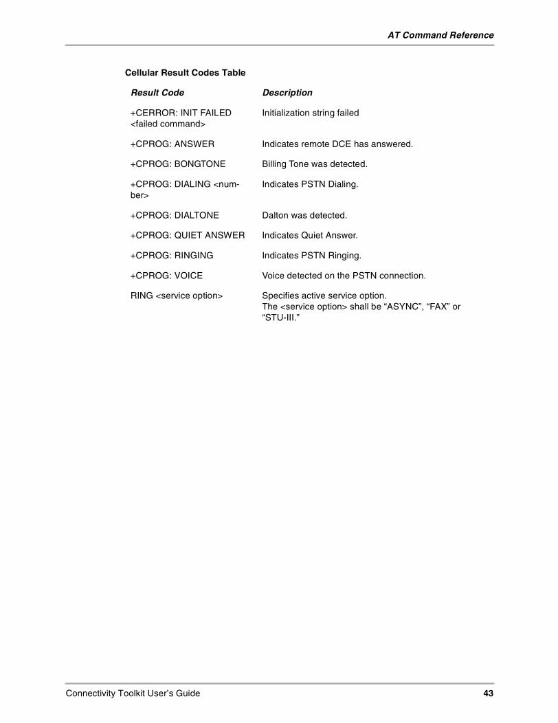
Cellular Result Codes Table
Result Code Description
+CERROR: INIT FAILED<failed command>
Initialization string failed
+CPROG: ANSWER Indicates remote DCE has answered.
+CPROG: BONGTONE Billing Tone was detected.
+CPROG: DIALING <num-ber>
Indicates PSTN Dialing.
+CPROG: DIALTONE Dalton was detected.
+CPROG: QUIET ANSWER Indicates Quiet Answer.
+CPROG: RINGING Indicates PSTN Ringing.
+CPROG: VOICE Voice detected on the PSTN connection.
RING <service option> Specifies active service option.The <service option> shall be “ASYNC”, “FAX” or“STU-III.”

44 Connectivity Toolkit User’s Guide
Glossary
Glossarycall forwarding. A feature that permits you to reroute incoming calls to a different telephonenumber, either all the time or only when your phone number is busy or doesn’t answer.
call history. A list of the last 199 calls you have sent or received.
call waiting. When you’re currently engaged in a call, a signal notifying you that another callhas arrived.
carrier features. Options available from your telephone service provider. Since these optionsvary, you must contact your service provider for detailed information.
command. An instruction that causes a device (such as a phone or a computer) to performan action.
data transmission. The technology of transmitting and receiving information overcommunication channels.
dialog box. A temporary box or window of information that prompts you to enter and/orselect information that is necessary for a task to continue.
DNS. Domain Name System, a mechanism on the Internet for translating the domain namesof host computers (such as server.company.com) into IP addresses.
DTMF. Dual Tone Multi-Frequency, a method of using tones to communicate commandsand responses to and from a master controlling unit. These are the tones you hear when youdial a telephone.
e-mail. Electronic mail, a store-and-forward service for text and graphical messages fromone computer to another. The information is stored for you until you log into the system toretrieve the messages.
field. A location where you enter data. A field is often displayed as a line where you canwrite information.
handset. Another name for any ordinary telephone; may refer to the part of the telephonecontaining the mouthpiece and receiver.
hard reset. A reset of your phone that erases all data.
IAP. Internet Access Provider, a service that provides companies and individuals with a linkto the Internet.
idle timeout. The amount of time the phone waits before dropping a connection with yourISP or dial-in server after a network application closes.
Internet. The set of interconnected networks that share the same network address schemeand use the TCP/IP protocol.
IP Address. Internet Protocol Address, the address that identifies the network to which eachcomputer on a TCP/IP network is attached as well as the computer’s unique identification.
ISP. Internet Service Provider, a vendor who provides direct access to the Internet.
point-to-point. A term used to describe a data channel which connects two—and onlytwo—computers.
prefix. The number you dial before the telephone number to reach an outside line.
protocol. A set of rules followed by two computers when they communicate with oneanother.
roaming. Using telephone services outside of the area covered by your home serviceprovider
script. A file used by some communications programs to automate logging ontocommunication services such as e-mail

Connectivity Toolkit User’s Guide 45
Glossary
scroll bar. A bar at the right border of a window whose contents are not completely visible.Each scroll bar contains two scroll arrows and a scroll box that you can tap to move throughthe contents of the window.
serial port. An input/output port used to connect serial devices, such as a mouse, externalmodem, or wireless phone to a computer
TCP/IP. Transmission Control Protocol/Internet Protocol, the standard rules used for datatransmission over the Internet

46 Connectivity Toolkit User’s Guide
Glossary

Connectivity Toolkit User’s Guide 47
Index
Aarea codes
adding 16change 16removing 17
Ccable
9-pin connector 4to your computer 4to your phone 4
call forwarding, definition 44call waiting, definition 44COM serial port
connect cable 4command, definition 44connecting the data cable
to your computer 4to your phone 4
Contact Manager 12contacts
creating 13details 13editing 13list 12type 12
Coolbar 8copy
see sync
Ddata cable
to your computer 4to your phone 4
Data transmission, definition 44dialog box, definition 44DNS, definition 44DTMF, definition 44
Eedit an existing contact 13e-mail, definition 44
Ffax 5field, definition 44
Hhandset, definition 44hard reset, definition 44help
online help 5
Iidle timeout, definition 44
importcalendar 23contatcts 22
Internet, definition 44IP address 44IP Address, definition 44ISP, definition 44
Mmerge/sync priorities 11multiple phones
managing 6matching 6open phone 6phone documents 6sync current 6
Nnew contacts
creating 13editing 13
Oonline help 5Open Phone 6
PPhone Detected window 7point-to-point, definition 44port 4Preferences 9
General Tab 9prefix, definition 44protocol, definition 44
QQuickLink
QuickLink Fax 5QuickLink Mobile 5
Rrequirements 3Ringer Downloader 26ringers
download 26import 26
roaming, definition 44
Sscript, definition 44scroll bar, definition 45secret numbers
locking 17unlocking 17
serial port, definition 45

48 Connectivity Toolkit User’s Guide
sync 19between phone and document 11, 18between two documents 11, 18
Sync Current 6Sync Tab 9, 10Synchronizing contacts 19
TTCP/IP, definition 45troubleshooting 5
WWhere I can find information 5wireless modem 5


![Loading [MathJax]/jax/output/CommonHTML/jax](https://img.dokumen.tips/doc/110x75/625335b291158e3f663c6c05/loading-mathjaxjaxoutputcommonhtmljax.jpg)