Embed Size (px)
Citation preview
University of Illinois at Urbana-Champaign
Air Conditioning and Refrigeration Center A National Science Foundation/University Cooperative Research Center
Connection Methods for Non-Metallic, Flexible, Thin, Microchannel Heat Exchangers
N. Pourmohamadian, M. L. Philpott, and M. A. Shannon
ACRC TR-231 August 2004
For additional information:
Air Conditioning and Refrigeration Center University of Illinois Mechanical & Industrial Engineering Dept. 1206 West Green Street Prepared as part of ACRC Project #144 Urbana, IL 61801 Non-metallic, Flexible, Thin, Multichannel Heat Exchangers for Refrigeration and Air-Conditioning Applications (217) 333-3115 M. L. Philpott and M. A. Shannon, Principal Investigators

The Air Conditioning and Refrigeration Center was founded in 1988 with a grant from the estate of Richard W. Kritzer, the founder of Peerless of America Inc. A State of Illinois Technology Challenge Grant helped build the laboratory facilities. The ACRC receives continuing support from the Richard W. Kritzer Endowment and the National Science Foundation. The following organizations have also become sponsors of the Center. Alcan Aluminum Corporation Arçelik A. S. Behr GmbH and Co. Carrier Corporation Cerro Flow Products, Inc. Copeland Corporation Daikin Industries, Ltd. Delphi Thermal and Interior Embraco S. A. Ford Motor Company Fujitsu General Limited General Motors Corporation Hill PHOENIX Hydro Aluminum Adrian, Inc. Ingersoll-Rand/Climate Control Lennox International, Inc. Manitowoc Ice, Inc. LG Electronics, Inc. Modine Manufacturing Co. Parker Hannifin Corporation Peerless of America, Inc. Samsung Electronics Co., Ltd. Sanden International, Inc. Sanyo Electric Co., Ltd. Tecumseh Products Company Trane Visteon Automotive Systems Wieland-Werke, AG Wolverine Tube, Inc. For additional information: Air Conditioning & Refrigeration Center Mechanical & Industrial Engineering Dept. University of Illinois 1206 West Green Street Urbana, IL 61801 217 333 3115

iii
Abstract
Non-metallic, flexible, thin, microchannel heat exchangers made from heat-sealable polyimide films have
recently been developed for refrigeration and air-conditioning applications. In order for these heat exchangers to
function properly and independently, robust and reliable connectors are needed. The connectors must be easy to
manufacture and assemble, hold high pressures without leaking, resist a pullout force, and have the ability to
connect to standard tubing and piping and different heat exchangers together in series and parallel. Three uniquely
different functional prototype connector designs have been developed, manufactured, and tested. The first includes
a machined metal connector internally embedded within the heat exchanger that is capable of holding pressures up
to 0.83 MPa and 65.5 N of pullout force before failure. The second connector design includes a two-piece polymer
assembly containing an o-ring used to seal around the inlet and outlet holes of the heat exchanger. The design
incorporates a 10-degree wedge that creates the sealing force when fully assembled with the heat exchanger and has
been pressure tested to 1.83 MPa without leaking and 73.6 N of pullout force applied before failure. A variation of
the design allows multiple heat exchangers to connect in series and in parallel. Finally, the third design contains no
additional parts and connects two heat exchangers together by thermally bonding the inlet of one heat exchanger to
the outlet of another. The thermally bonded connection was able to hold pressures greater than 2.07 MPa. Finally,
fatigue testing of the heat exchangers is conducted using an Instron machine to develop a stress amplitude versus
number of cycles to failure diagram for the zero pressure case.
iv
Table of Contents Page
Abstract......................................................................................................................... iii List of Figures ............................................................................................................... v
Chapter 1. Introduction and Overview......................................................................... 1 1.1 Project overview ............................................................................................................................. 1 1.2 Motivation........................................................................................................................................ 1 1.3 Literature review of microfluidic interconnects .......................................................................... 3 1.4 Research objectives....................................................................................................................... 5
Chapter 2. Design of Interconnects ............................................................................. 7 2.1 Previous connector used for the heat exchanger....................................................................... 7 2.2 Embedded connector..................................................................................................................... 8 2.3 Snap-in connector .......................................................................................................................... 9 2.4 Wedge connector ......................................................................................................................... 10 2.5 Thermally bonded connector ...................................................................................................... 12
Chapter 3. Manufacturing of Interconnects .............................................................. 14 3.1 Original heat exchanger............................................................................................................... 14 3.2 Embedded connector................................................................................................................... 16 3.3 Snap-in and wedge connector .................................................................................................... 18
3.3.1 The stereolithography process..............................................................................................................19 3.3.2 Snap-in connector.................................................................................................................................20 3.3.3 Wedge connector..................................................................................................................................21
3.4 Thermally bonded connector ...................................................................................................... 24 Chapter 4. Testing of Interconnects and Heat Exchanger....................................... 26
4.1 Pressure testing of interconnects .............................................................................................. 26 4.1.1 Experimental setup ...............................................................................................................................26 4.1.2 Experimental results .............................................................................................................................27
4.2 Pullout force testing of interconnects........................................................................................ 30 4.2.1 Experimental setup ...............................................................................................................................30 4.2.2 Experimental results .............................................................................................................................32
4.3 Fatigue testing of heat exchanger .............................................................................................. 34 4.3.1 Experimental setup ...............................................................................................................................34 4.3.2 Experimental results .............................................................................................................................36
Chapter 5. Conclusions and Recommendations...................................................... 39 5.1 Conclusions .................................................................................................................................. 39 5.2 Recommendations ....................................................................................................................... 40
References................................................................................................................... 41
Appendix A – Engineering Drawings......................................................................... 43
Appendix B – Wireframe Drawings............................................................................ 64

v
List of Figures Page
Figure 1-1. Integrated mesoscopic cooling circuit (IMMC) .........................................................................................2 Figure 1-2. Schematic of compact non-metallic heat exchanger comprised of multiple modules manifolded
together ..................................................................................................................................................................3 Figure 1-3. Tsai and Lin schematic of Mylar sealant interconnects, discrete process (left) and integrated
process (right) ........................................................................................................................................................3 Figure 1-4. Fabrication method for Pattekar and Kothare Teflon capillary..................................................................4 Figure 1-5. Photographs of Yao et al. micromachined o-rings .....................................................................................5 Figure 2-1. Initial connector for heat exchanger (a) 3-D solid model (b) connector assembled with heat
exchanger...............................................................................................................................................................8 Figure 2-2. Embedded connector design (a) Drawing with dimensions in mm (b) 3-D solid model ...........................9 Figure 2-3. Wireframe drawing of original inlet hole (left) and new inlet hole (right) ................................................9 Figure 2-4. Snap-in connector shown in (a) exploded view and (b) assembled view (c) top piece showing
bottom surface with o-ring...................................................................................................................................10 Figure 2-5. Three piece wedge connector (a) exploded view (b) assembled view (c) cross-sectional .......................11 Figure 2-6. Two piece connector (a) exploded view (b) assembled view (c) cross-section .......................................11 Figure 2-7. Connecting multiple heat exchangers using the wedge method. (a) exploded view of 3-D model
(b) cross sectional view of connecting in series (c) cross sectional view of connecting in parallel.....................12 Figure 2-8. Exploded view of thermally bonded connection with full size heat exchangers......................................13 Figure 2-9. Test size of thermally bonded connection (a) exploded view (b) assembled view ..................................13 Figure 3-1. Exploded view of heat exchanger layers (1) inlet and outlet layer (2) manifold layer (3) channels
layer (4) cap layer ................................................................................................................................................14 Figure 3-2. Profiles for temperature, load, and pressure during bonding of the heat exchanger ................................15 Figure 3-3. Heat exchanger fabrication equipment (a) tangential knife cutter (b) vacuum oven (c) inside
bonder chamber with stack between top and bottom bonder plates.....................................................................16 Figure 3-4. (a) Stainless steel embedded connector made from welding tubing to base (b) Failure of weld
during bonding.....................................................................................................................................................16 Figure 3-5. (a) Stainless steel jig used to achieve 50 micron thickness of embedded connecter base (b)
Drawing of jig (cross sectional view) ..................................................................................................................17 Figure 3-6. Modified top bonder plate for bonding embedded connector within heat exchanger layers....................18 Figure 3-7. Machined brass embedded connector (a) close-up (b) laminated within heat exchanger layers and
ready for compression fittings .............................................................................................................................18 Figure 3-8. (a) Stereolithography Apparatus (b) close-up of build platform and resin container inside the SLA
chamber ...............................................................................................................................................................19 Figure 3-9. Snap-in connector with supports on the SLA platform in 3-D Lightyear (a) original design (b)
design with decreased dimensions.......................................................................................................................20 Figure 3-10. Snap-in connector (a) assembled with heat exchanger (b) top and bottom piece separated (c)
original design assembled (d) smaller version assembled (e) common failure point (circled) of bottom piece.....................................................................................................................................................................21

vi
Figure 3-11. Wedge connector with supports on the SLA platform in 3-D Lightyear (a) two piece with screw wedge connector (b) two piece wedge connector (c) three piece wedge connector ............................................21
Figure 3-12. Three piece wedge connector shown with single channel test heat exchanger (a) exploded view (b) assembled view ..............................................................................................................................................22
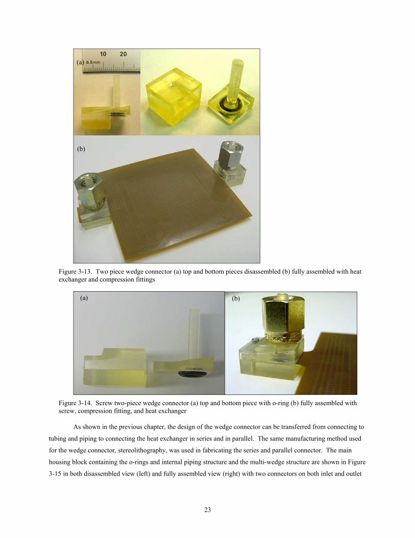
Figure 3-13. Two piece wedge connector (a) top and bottom pieces disassembled (b) fully assembled with heat exchanger and compression fittings.....................................................................................................................23
Figure 3-14. Screw two-piece wedge connector (a) top and bottom piece with o-ring (b) fully assembled with screw, compression fitting, and heat exchanger ..................................................................................................23
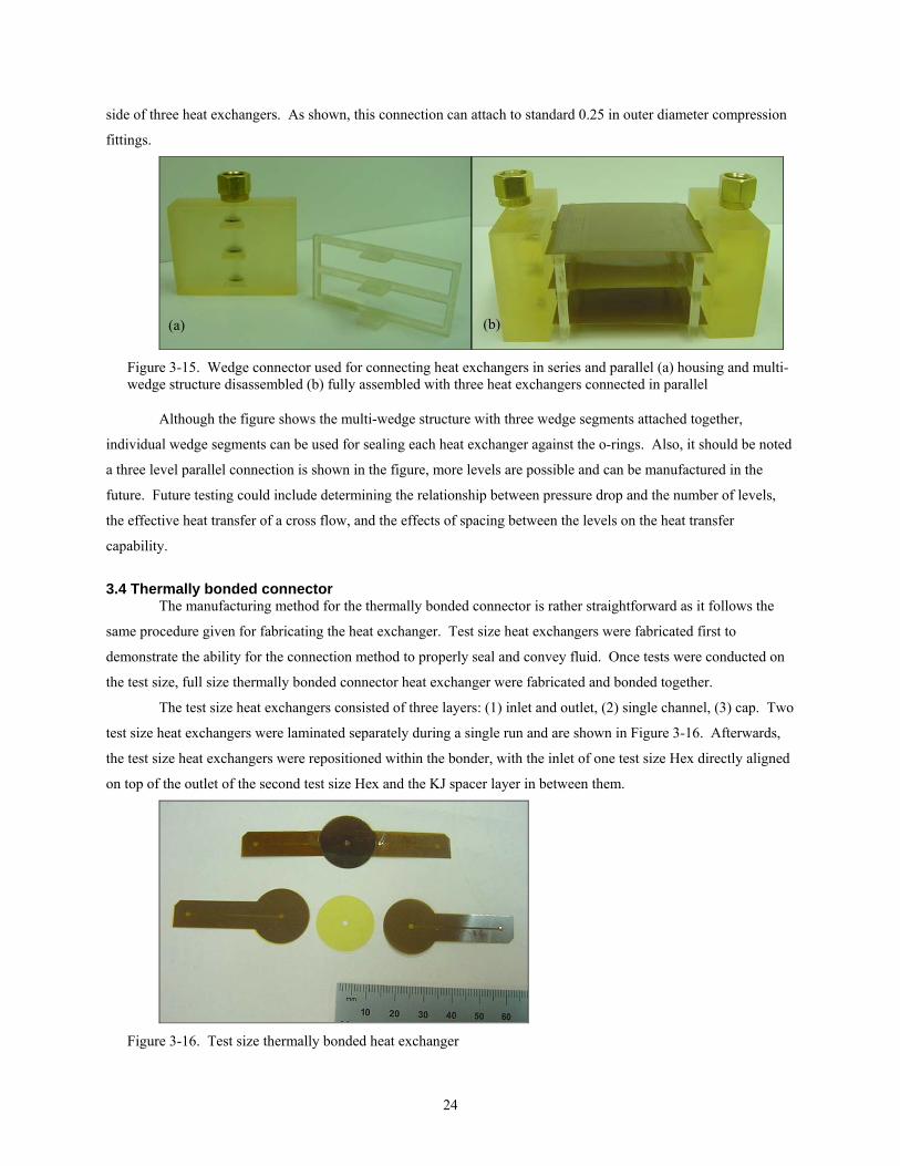
Figure 3-15. Wedge connector used for connecting heat exchangers in series and parallel (a) housing and multi-wedge structure disassembled (b) fully assembled with three heat exchangers connected in parallel.......24
Figure 3-16. Test size thermally bonded heat exchanger............................................................................................24 Figure 3-17. Full size thermally bonded connection (a) close-up of overlapping region (b) two heat exchangers
bonded together ...................................................................................................................................................25 Figure 4-1. Schematic of pressure test setup ..............................................................................................................26 Figure 4-2. Pressure test setup with wedge connector on heat exchanger ..................................................................27 Figure 4-3. Snap-in connector pressure test................................................................................................................27 Figure 4-4. Close-up of embedded connector edge bead............................................................................................28 Figure 4-5. Embedded connector pressure test failure (a) inside water bath (b) delamination of heat exchanger
inlet/outlet layer...................................................................................................................................................28 Figure 4-6. Wedge connector failure during pressure test ..........................................................................................29 Figure 4-7. Thermally bonded connection pressure test .............................................................................................29 Figure 4-8. Summary of pressure testing results ........................................................................................................30 Figure 4-9. Pullout force test setup.............................................................................................................................30 Figure 4-10. Close-up of pullout force test (a) wedge connector (b) embedded connector........................................31 Figure 4-11. Metal plate used to isolate tube section during pullout force test ..........................................................31 Figure 4-12. Wedge with screw connector pullout force testing setup.......................................................................32 Figure 4-13. Embedded connector failure after pullout force test ..............................................................................32 Figure 4-14. Wedge with screw connector failure after pullout force test..................................................................33 Figure 4-15. Pullout force testing results....................................................................................................................33 Figure 4-16. Failure of wedge connector....................................................................................................................34 Figure 4-17. Design of grips used in fatigue testing (a) exploded view (b) side view of assembled grip ..................35 Figure 4-18. Fatigue wedge heat exchangers (a) wireframe drawing (b) fabricated ..................................................35 Figure 4-19. Fatigue heat exchanger loaded on Instron machine ...............................................................................36 Figure 4-20. Model of rectangular filleted bar in tension ...........................................................................................36 Figure 4-21. Failure of fatigue heat exchanger with sharp corners.............................................................................37 Figure 4-22. Failure of fatigue heat exchanger with rounded corners ........................................................................37 Figure 4-23. S-N diagram for heat exchanger ............................................................................................................38

1
Chapter 1. Introduction and Overview
1.1 Project overview The objective of this research is to investigate the use of non-metallic heat exchangers made from polymers
in refrigeration and air-conditioning applications. These heat exchangers are quite unique in that they are thin (200
microns), flexible (can be repeatably bent without failure and able to conform to different geometries), and
extremely lightweight (< 1 gram). The polymer used to manufacture the heat exchanger includes two types of
Kapton® (DuPont) polyimide film. Kapton® is a high performance polymer known for its excellent thermal
stability, mechanical toughness, high strength, and superior chemical resistance. The Kapton® heat exchanger
comprises of four mechanically patterned layers that are thermally laminated together to form the sealed structure.
This manufacturing method can potentially be transferred to low cost mass production for the heat exchanger.
Testing of 100 mm by 100 mm square patches of the heat exchanger demonstrate the ability to hold pressure greater
than 1.72 MPa (250 psi) and transfer 2500 W/m2 using R-134a on the refrigerant side [1]. The heat exchanger
design and manufacturing procedure lends itself to many different configurations that can be optimized for a
particular application.
Several important issues still remain to be resolved concerning the heat exchangers before transferring to an
industrial application. One of the important questions to be resolved includes how to adequately connect the heat
exchanger to refrigerant piping and tubing, as well as connecting multiple heat exchangers together in series and
parallel. This paper presents several different functional connector prototypes that were designed, developed,
manufactured and tested to allow the heat exchanger to connect in piping and in series and parallel.
This work was funded by the 27 member companies of the Air-Conditioning and Refrigeration Center
(ACRC), an Industry/University Cooperative Research Center founded by the National Science Foundation, at the
University of Illinois at Urbana-Champaign. The ACRC project number is 144 and the work began in August 2002.
1.2 Motivation Lightweight heat exchangers are essential to applications requiring high heat flux (greater than 1000 W/m2)
across thin cross-sections and minimal pressure losses from fluid flow common in microchannels. Non-metallic
heat exchangers, as compared to metal heat exchangers, are able to conform to fit geometries, stretch and bend
repeatably without breaking, adjust to changes in temperature and pressure to keep flow losses from changing, and
remain very chemically resistant [2]. In addition, thin non-metallic heat exchangers have the potential to serve as
both a fluid channel and fin for refrigeration and air-conditioning applications. Many potential applications exist for
these heat exchangers that include but not limited to:
• compact, ultra lightweight heat exchangers for automotive and aircraft A/C systems
• heat exchangers for handling corrosive and acidic liquids and gases
• microelectronics cooling
• cooling for protective clothing and personal microclimate control
• car seat heating and cooling [3,4].
To reach the potential of these non-metallic heat exchangers, further developments need to be made to
counter existing metal heat exchangers, mainly aluminum [5]. Initial attempts of manufacturing non-metallic heat

2
exchangers include thermoplastic injection molding, compression molding, and low pressure injection molding of
thermosetting polymers. Although some success was achieved, the lack of flexibility and incompatibility with
refrigerants of most thermoplastics makes their use problematic [1].
In 1999, Mangriotis et al. reported flexible, thin-film heat exchangers made from photosensitive polyimide
layers with microchannel dimensions of 1 mm width and 30 µm height [6]. Multiple layers of spin-coated DuPont
PI-2721 polymide used to define fluid and vent channel geometries were made using batch-mode semiconductor
processing. To seal the device, a 75 µm thick Kapton® HN film was solvent bonded to the polyimide layers [7].
Problems with these non-metallic heat exchangers included degradation of the interfacial seal between the polyimide
and Kapton® due to vapor evolution (inherent in solvent bonding) and very high pressure losses (> 100 kPa) over 20
mm channel lengths with 30 µm interior channel height. To reduce the pressure loss over long channel lengths,
greater channel heights are required, often a difficult task using spin coated layers.
Selby et al. (1999) designed and fabricated flexible, thin, microchannel heat exchangers for two-phase
refrigerants made from KJ and EKJ Kapton® polyimide film [8]. Initially, these heat exchangers were developed
for the condenser and evaporator of an integrated micro vapor compression cooler, named the IMCC, shown in
Figure 1-1 [9]. The heat exchangers for the IMCC are approximately 250 µm thick, 100 by 100 mm wide, and were
pressure tested up to 1.723 MPa (250 psi) using R-134a refrigerant. Before being pressurized, the individual
channel dimensions range from 50 to 100 µm in width and 250 to 1000 µm in height. Heat transfer coefficients have
been measured on the refrigerant side up to about 1000 W/m2°C for single phase liquid to over 8000 W/m2°C for
two-phase evaporation, with heat fluxes ranging from 0 to 3500 W/m2 [1].
Figure 1-1. Integrated mesoscopic cooling circuit (IMMC)
From the initial work done on the non-metallic heat exchanger, further work is required to move this
technology to the next stage of development, which is integration into current and new types of refrigeration and air
conditioning systems. With robust and reliable connection methods to piping and manifold systems, then non-
metallic heat exchangers, as shown in the schematic of Figure 1-2 can be constructed, tested, and characterized.
This is a unique type of manifold heat exchanger; with each individual non-metallic heat exchanger serving as both
the refrigerant piping and fin structure [1].

3
Air Flow
Refrigerant IN Refrigerant OUT
Figure 1-2. Schematic of compact non-metallic heat exchanger comprised of multiple modules manifolded together
1.3 Literature review of microfluidic interconnects Microfluidic interconnects found in literature primarily involve inserting a glass or plastic capillary within
drilled holes of glass or silicon substrates with various methods of sealing. Typically microchannels are etched in
the substrate using conventional microfabrication techniques such as deep reactive ion etching. One of the main
applications includes use in microfluidic devices for fluid analysis to on-chip chemical and biological processing
[10-22]. A brief overview of several micro-to-macro interconnects are presented here.
Tsai and Lin (2001) developed micro-to-macro fluidic interconnects using an integrated Mylar film as the
sealant in both discrete and integrated processes, as shown in Figure 1-3. For the discrete process, a 14 µm thick
Mylar film is manually cut into square pieces and pierced through the center with a 320 µm diameter glass capillary.
The capillary/Mylar assembly is placed inside an etched fluidic port on a glass/silicon substrate and held in place
with a polyvinylidene chloride (PVDC) adhesive coating on the Mylar. After heating at 180 C for five minutes on a
hot plate to promote adhesion, droplets of instant glue are applied around the interconnection hole to enhance the
holding force and complete the process. The integrated process is similar to the discrete process, but incorporates
the interconnect while the microchannels are fabricated. Testing results for the Mylar interconnects indicate up to
190 kPa (27.56 psi) of pressure without leakage and up to 2.065 N of pullout force before failure [11].
Figure 1-3. Tsai and Lin schematic of Mylar sealant interconnects, discrete process (left) and integrated process (right)
Pattekar and Kothare (2003) use Teflon (PTFE) capillaries placed within precisely drilled inlet/outlet holes
on a Pyrex wafer anodically bonded to a silicon substrate. The Pyrex/silicon substrate contains microchannels of
4
300 µm wide and 1000 µm wide with inlet/outlet holes of 1.8 mm in diameter. The 1.68 mm diameter Teflon
capillary must be chemically treated (sodium/naphthalene solution, methanol, glacial acetic acid solution) to remove
the fluorine atoms and introduce carbonyl and carboxylic acid groups on the surface, making the PTFE a wetted
surface and able to bond using conventional epoxies.
After treatment, the interconnect is inserted within the inlet/outlet holes of the substrate placed on a
hotplate set at 380°C. The bottom surface (inserted end) of the Teflon capillary is briefly heated (5 seconds) against
the hot silicon substrate until melting occurs. Then the capillary is pulled upward out of the microchannel and
positioned inside the inlet/outlet hole where an integrated “o-ring” of Teflon is formed when cooled. This step holds
the capillary in place when a high temperature epoxy (Duralco 4460) is applied around the perimeter of the capillary
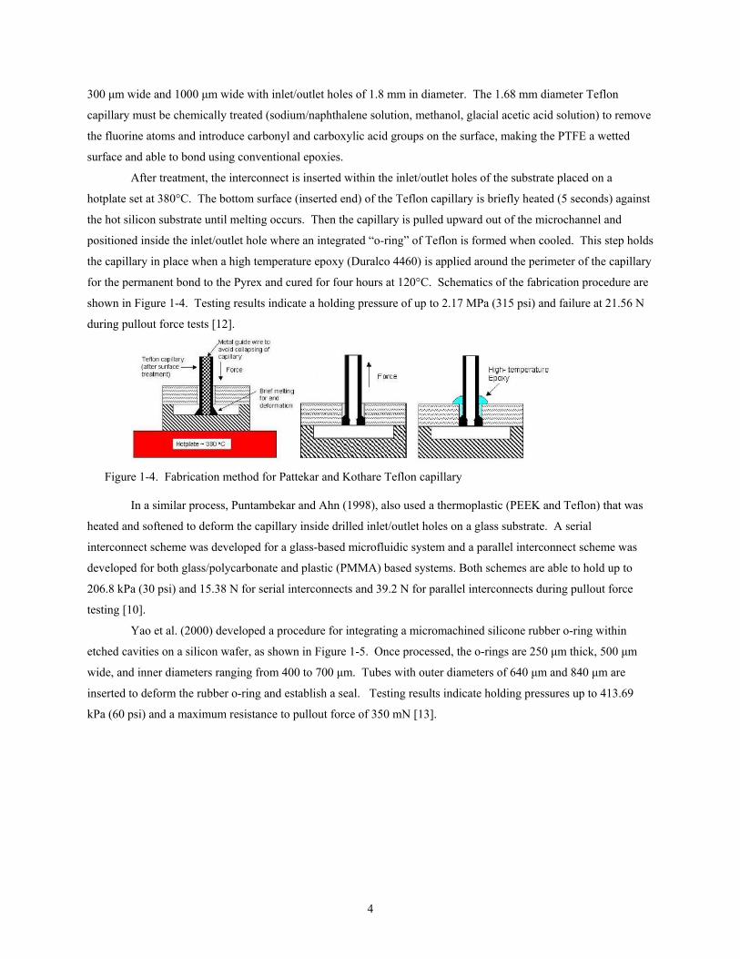
for the permanent bond to the Pyrex and cured for four hours at 120°C. Schematics of the fabrication procedure are
shown in Figure 1-4. Testing results indicate a holding pressure of up to 2.17 MPa (315 psi) and failure at 21.56 N
during pullout force tests [12].
Figure 1-4. Fabrication method for Pattekar and Kothare Teflon capillary
In a similar process, Puntambekar and Ahn (1998), also used a thermoplastic (PEEK and Teflon) that was
heated and softened to deform the capillary inside drilled inlet/outlet holes on a glass substrate. A serial
interconnect scheme was developed for a glass-based microfluidic system and a parallel interconnect scheme was
developed for both glass/polycarbonate and plastic (PMMA) based systems. Both schemes are able to hold up to
206.8 kPa (30 psi) and 15.38 N for serial interconnects and 39.2 N for parallel interconnects during pullout force
testing [10].
Yao et al. (2000) developed a procedure for integrating a micromachined silicone rubber o-ring within
etched cavities on a silicon wafer, as shown in Figure 1-5. Once processed, the o-rings are 250 µm thick, 500 µm
wide, and inner diameters ranging from 400 to 700 µm. Tubes with outer diameters of 640 µm and 840 µm are
inserted to deform the rubber o-ring and establish a seal. Testing results indicate holding pressures up to 413.69
kPa (60 psi) and a maximum resistance to pullout force of 350 mN [13].

5
Figure 1-5. Photographs of Yao et al. micromachined o-rings
Polydimethylsioxane (PDMS) is another material being used for microfluidic applications, such as
interconnects [14, 15], due to simple and rapid processing (compared to traditional MEMS etching and bonding
procedures) and compatibility with biological systems. Li and Chen (2003) developed through-hole and “L-shaped”
PDMS interconnects for glass and plastic tubing. The PDMS film is approximately 2 mm thick, cut into 4 mm by 4
mm squares, and pierced by a 840 µm diameter glass tube. The interconnect and substrate are cleaned, baked to
remove moisture, and followed by oxygen plasma surface activation prior to bonding. After activation, the PDMS
interconnects are bonded to the silicon substrate and placed on a hotplate for 30 minutes at 145°C. Testing results
for PDMS interconnects show a maximum leakage pressure of 510 kPa (75 psi) and maximum pullout force of 800
mN [14].
1.4 Research objectives In order for the non-metallic heat exchangers to function properly and independently, connection methods
are needed between them and high pressure tubing and piping, as well as between multiple heat exchangers. The
difficulty lies in conveying fluid from flat polymer layers to round, standardized tubing profiles without significant
pressure loss or leakage.
This report presents four uniquely different interconnects designed for the non-metallic heat exchanger
including the manufacturing methods for each and the results of pressure leaking testing and pullout force testing.
In addition, results for cyclic loading testing of the heat exchanger are presented for the zero pressure case.
Chapter 2 presents the design stage of development for the connectors. It begins by providing the original
connector used for the heat exchanger and then presents the designs developed for this paper. The individual
connector sections include the design method employed for each, including 3-D SolidWorks models and necessary
modifications made to the heat exchanger to accommodate the connectors.
Chapter 3 provides the manufacturing procedure for both the heat exchanger and the individual connectors.
The first section describes the process for manufacturing the original heat exchanger as established by Selby et al.
Next, the manufacturing method for the embedded connector is given with photographs of the completed part and a
heat exchanger completed with embedded connectors laminated within the layers. Then, a brief overview of the
stereolithography process is given as an introduction to the manufacturing procedure of the snap-in and wedge
connectors. Recommendations on build styles and post-manufacturing procedures are given for both connectors as
well as photographs of the completed parts. Finally, the thermally bonded connector fabrication procedure is given
as well as photographs of the completed parts.

6
Chapter 4 is divided into three testing sections: pressure leakage testing and pullout force testing of the
connectors, and fatigue testing of the heat exchangers. For each testing section, the experimental setup is described
first, followed by the experimental results. The connectors tested are summarized in a graph alongside with other
connectors found in literature for both pressure testing and pullout force testing. The fatigue testing results are given
in the form of a stress amplitude versus number of cycles to failure (S-N) curve on a log-log scale.
Chapter 5 contains the conclusions of this research and provides recommendations of future work for
further consideration of the connectors and heat exchanger.
Appendix A gives the detailed engineering drawings for all parts designed and fabricated throughout this
work, including each connector design
Appendix B provides the wireframe drawings for the layers of heat exchangers used throughout the work,
including modifications made for individual connectors.

7
Chapter 2. Design of Interconnects
The major challenge in the connector design is finding an adequate and robust way to connect a thin, flat
inlet and outlet to standard tubing and piping. The current method of fabricating the heat exchanger (Hex) does not
allow much flexibility in altering the inlet and outlet. To overcome this difficulty, four connectors were designed
and manufactured based on these constraints.
The first connector incorporates a machined copper piece, referred to as the embedded connector, into the
layers of the heat exchanger during bonding. An advantage to this approach is the elimination of any post processes
after the heat exchanger is manufactured. The embedded connector has the capability to fit standard compression
fittings and the potential to connect several heat exchangers in series and in parallel.
The second connector is an external two piece polymer assembly that encompasses the inlet and outlet
holes of the heat exchanger. The two pieces fit together to create a sealing force of an o-ring around the inlet/outlet
when the two pieces are assembled together. Similar to the snap-in connector, the third connector is also a two piece
polymer assembly. In this case, a ten-degree wedge is present to provide the sealing force of the o-ring. Standard
compression tube fittings also can be added to the wedge connector, and the wedge design lends itself to connecting
multiple heat exchangers in series and parallel.
In contrast, a fourth connector design involves no additional parts and is used to connect multiple heat
exchangers together. The inlet of one heat exchanger is directly positioned on top of the outlet of another heat
exchanger and the two surfaces are thermally bonded together in the same manner the layers of the Hex. The
limitation of this connector is that it cannot be used to connect to standard tubing and fittings, and only used to
connect heat exchangers together in series or parallel.
2.1 Previous connector used for the heat exchanger The initial connector design of the heat exchanger involved a fitting made from stereolithography (SLA)
resin as shown in Figure 2-1. The connector is attached using a refrigerant friendly epoxy applied to between the
bottom surface of the fitting and the top layer of the Hex around the inlet hole. Since the epoxy is manually applied
and the requirement of cleanliness of the adhering surfaces is paramount, this process proved to be manually
intensive. Common problems associated with this connection method included epoxy blocking the inlet hole and
inconsistent epoxy film thicknesses.

8
Figure 2-1. Initial connector for heat exchanger (a) 3-D solid model (b) connector assembled with heat exchanger
The objectives of the new connector designs are to eliminate using epoxies, simplify the assembly of the
connector to the heat exchanger, and add robustness. Presented here are four alternative solutions to connecting the
heat exchanger to standard tubing and piping and to one another in series or parallel.
2.2 Embedded connector The first design for interconnects incorporates a connector within the heat exchanger during the bonding
process. Several advantages with this method include the elimination of any post production after the heat
exchanger is made, the heat exchanger remains flexible, and only a small amount of additional weight is added.
The inspiration for this connector came from the shape of a rivet containing a base and a tube. Several
different size rivets were considered for implementation; however complications arose, most importantly the curved
shape of the base. The major problem arises when trying to bond the rivet inside the heat exchanger since the
difference in thickness between the base and the overall thickness of the heat exchanger will cause a non-uniform
bond. Since the thickness of the heat exchanger stack must remain constant during bonding and the base of this
connector should be contained within the layers for adequate sealing, the base was designed to be flat and match the
thickness of an individual layer of Kapton® (50µm). The embedded connector shown in Figure 2-2 provides a
solution to these constraints and consists of two regions: the tube and the base.
The outer diameter of the tube was chosen as 0.125 in (3.175 mm) as it is a standard size for Swagelok®
compression fittings. The inner diameter selected, 0.07 in (1.8 mm), was also based on a standard size for metal
tubing. The tube can be modeled as a cylinder and the burst pressure can be calculated from the tangential stress.
Assuming that the longitudinal elongation is constant around the circumference of the cylinder, the equation for
tangential stress is given as
22
22222 /)(
io
iooiooiit rr
rpprrrprp−
−−−=σ
where pi is the inner pressure, po is the outer pressure, ri is the inner radius, ro is the outer radius, and r is the radius
of interest. Setting r = ri (location of maximum stress), σt equal to the yield strength of copper (69 MPa, 10 ksi), and
po to atmospheric pressure, the burst pressure (pi) becomes approximately 36 MPa (5250 psi) [23, 29].
(a) (b)

9
Figure 2-2. Embedded connector design (a) Drawing with dimensions in mm (b) 3-D solid model
2.3 Snap-in connector The second design shifted from the idea of an internal connection to externally applying a connector on the
heat exchanger. For sealing purposes, the aim of this external connection was to fully encompass the inlet and outlet
holes by having contact not only on the inlet/outlet layer, but also the cap layer as well. The original placement of
the inlet and outlet holes within the square area of the heat exchanger did not allow a connector to fully encompass
these critical sealing regions in a practical way. The solution to this problem was extending the inlet and outlet
holes outside the main square area as shown in Figure 2-3.
Figure 2-3. Wireframe drawing of original inlet hole (left) and new inlet hole (right)
The design and snap-in concept was influenced by a typical insulation displacement connectors (IDC)
found in the electronics industry for connecting ribbon wire to electrical contacts [25]. Instead of conveying current
as done with IDC connection, the objective of the snap-in connector was to convey high pressure fluids without
leaking. A two-piece design was made to include a top piece and bottom piece as shown in Figure 2-4.
Inlet Hole
Base
Tube
(a) (b)

10
Figure 2-4. Snap-in connector shown in (a) exploded view and (b) assembled view (c) top piece showing bottom surface with o-ring
The top piece includes a 0.125 in (3.175 mm) outer diameter tube with a 0.07 in (1.8 mm) inner diameter
channel that extends to the bottom surface. On this bottom surface, an o-ring surrounds the entrance to the inner
channel as shown in Figure 2-4c. The o-ring size was chosen as 008 (0.0625 in cross section width, 0.1875 in ID,
0.3125 in OD) to prevent the o-ring from overlapping the inlet hole. The top piece is positioned directly on the
inlet/outlet layer of the heat exchanger with the center of the inner channel aligned with the center of the inlet hole
of the heat exchanger. The bottom piece is then placed below the top piece and the two are assembled together
around the extended inlet hole of the heat exchanger. Tabs on the side of the top piece lock into place under the
corresponding protrusions on the bottom piece. The bottom piece serves two purposes: to hold the top piece in place
and more importantly, create the necessary force to seal the o-ring around the inlet hole of the heat exchanger.
In subsequent designs, the overall size of both pieces was reduced to eliminate unnecessary volume. Also,
the height of the tabs on the top piece was modified in an attempt to increase the sealing force of the o-ring when
assembled with the bottom piece. The detailed drawings for all the designs of the snap-in connector top and bottom
pieces are found in the appendix.
2.4 Wedge connector Similar to the snap-in connector, the wedge connector is also an external connection that encompasses the
inlet and outlet holes of the modified heat exchanger. The difference between the two designs lies in the method of
providing the sealing force. Instead of using two pieces snapping together, a wedge provides the necessary force to
seal the o-ring around the inlet hole. The wedge connector is a three piece assembly shown in Figure 2-5 containing
the top piece, housing, and the wedge.
Bottom Piece
Top Piece
(a) (b) (c)
Tab

11
Figure 2-5. Three piece wedge connector (a) exploded view (b) assembled view (c) cross-sectional
Again, the top piece in this connector houses the tube with an outer diameter of 0.125 in (3.175 mm) and
0.07 in (1.8 mm) inner diameter channel that extends to the bottom surface. The same size o-ring used in the snap-
in connector surrounds the entrance to the inner channel and is located on the bottom surface of the top piece. The
housing mainly serves as a support structure to hold the top piece in place when the wedge is inserted. To provide
the sealing force between the o-ring and inlet of the Hex, the wedge is driven between the bottom of the Hex and the
inside of the housing as shown in Figure 2-5b (without the Hex present). Tabs on the sides of the wedge provide a
gripping area to remove the wedge once it is assembled.
In an attempt to simplify the design, the wedge and the top piece were combined together to eliminate
unnecessary additional parts. This improvement resulted in the two-piece wedge connector shown in Figure 2-6 in
exploded, assembled, and cross sectional views.
Figure 2-6. Two piece connector (a) exploded view (b) assembled view (c) cross-section
Further improvements to the wedge connector were also made and include increasing the resistance to
separation of the two pieces by a pullout force. The first design combines the two piece wedge connector with the
tabs from the snap-in connector. The wedge remains the sealing method while the snap-in concept is strictly used to
hold the two pieces together. The second method designed for improving resistance to a pullout force places a
screw through the top piece, heat exchanger, and the bottom piece. Both pieces of the wedge connector and the heat
(a) (b) (c)
(a) (b) (c)
Top Piece
Wedge
Housing
O-ring
Tabs
12
exchanger are extended 5 mm and a 0-80 (5/16 in length) socket cap screw is positioned in the center of the
extended area. Drawings of the components are provided in the appendix.
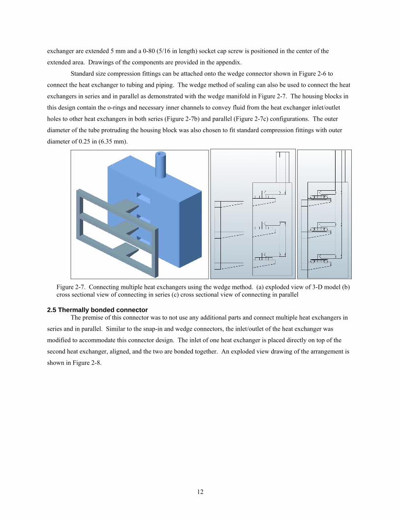
Standard size compression fittings can be attached onto the wedge connector shown in Figure 2-6 to
connect the heat exchanger to tubing and piping. The wedge method of sealing can also be used to connect the heat
exchangers in series and in parallel as demonstrated with the wedge manifold in Figure 2-7. The housing blocks in
this design contain the o-rings and necessary inner channels to convey fluid from the heat exchanger inlet/outlet
holes to other heat exchangers in both series (Figure 2-7b) and parallel (Figure 2-7c) configurations. The outer
diameter of the tube protruding the housing block was also chosen to fit standard compression fittings with outer
diameter of 0.25 in (6.35 mm).
Figure 2-7. Connecting multiple heat exchangers using the wedge method. (a) exploded view of 3-D model (b) cross sectional view of connecting in series (c) cross sectional view of connecting in parallel
2.5 Thermally bonded connector The premise of this connector was to not use any additional parts and connect multiple heat exchangers in
series and in parallel. Similar to the snap-in and wedge connectors, the inlet/outlet of the heat exchanger was
modified to accommodate this connector design. The inlet of one heat exchanger is placed directly on top of the
second heat exchanger, aligned, and the two are bonded together. An exploded view drawing of the arrangement is
shown in Figure 2-8.

13
Figure 2-8. Exploded view of thermally bonded connection with full size heat exchangers
To demonstrate the functionality of this type of connector, smaller size test versions were designed before
making the full scale heat exchanger. The test size heat exchangers, shown in Figure 2-9, consist of only three
layers of Kapton® with an inlet/outlet layer, a single channel layer, and a cap layer. The width of the test Hex is 10
mm wide to accommodate a wedge or snap-in connector for conveying fluid during leak testing. The channel length
is 30 mm and the overlapping circular area used for bonding two Hex together is 20 mm in diameter. The two heat
exchanger connection areas were designed to be bonded together with a 50 µm thick KJ spacer layer in between
them.
Figure 2-9. Test size of thermally bonded connection (a) exploded view (b) assembled view
A limitation to this design is the inability to connect to standard tubing and piping, rather only in series and
in parallel. The pressure the thermally bonded connector can withstand without leaking is limited by the connection
to the piping structure delivering the fluid to the heat exchangers. Further improvement to this connector can be to
optimize the overlapping area to reduce the amount of material used and increase the surface area of the heat
exchangers connected together. With decreased overlapping area, the pullout force necessary to separate the
connection also decreases. The optimal area of the connector depends on the application of the heat exchangers, if
pullout force is not a major concern, then a smaller area can be used.
Test Hex 1 Test Hex 2 Spacer
(b)
(a)
14
Chapter 3. Manufacturing of Interconnects
The designs of the four different interconnects presented in the previous chapter were manufactured and the
procedure is given in this chapter. First, an overview of how the original heat exchanger was fabricated, without any
connection method present, is described. Some of the process steps in the heat exchanger fabrication explain the
reasons why some of the designs and manufacturing techniques for the connectors were chosen. This section is
followed by the details for manufacturing each connector and the procedures considered and ultimately used.
3.1 Original heat exchanger As noted earlier, the original heat exchanger design was 100 mm by 100 mm and used as the condenser and
evaporator for the IMCC. For this current project, a smaller area of 60 mm by 60 mm is used for all heat exchangers
fabricated. The manufacturing process for the original heat exchanger is given in a paper by Selby et al. A brief
overview of the process will be given here, and for the detailed process refer to [8].
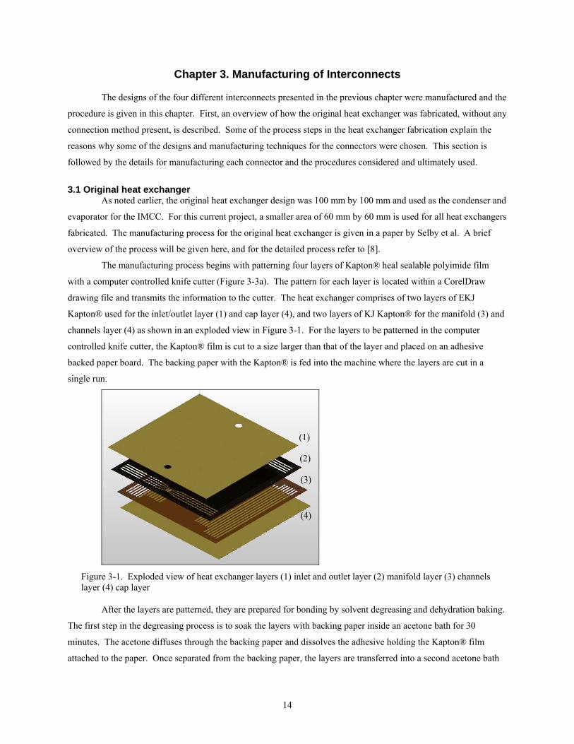
The manufacturing process begins with patterning four layers of Kapton® heal sealable polyimide film
with a computer controlled knife cutter (Figure 3-3a). The pattern for each layer is located within a CorelDraw
drawing file and transmits the information to the cutter. The heat exchanger comprises of two layers of EKJ
Kapton® used for the inlet/outlet layer (1) and cap layer (4), and two layers of KJ Kapton® for the manifold (3) and
channels layer (4) as shown in an exploded view in Figure 3-1. For the layers to be patterned in the computer
controlled knife cutter, the Kapton® film is cut to a size larger than that of the layer and placed on an adhesive
backed paper board. The backing paper with the Kapton® is fed into the machine where the layers are cut in a
single run.
Figure 3-1. Exploded view of heat exchanger layers (1) inlet and outlet layer (2) manifold layer (3) channels layer (4) cap layer
After the layers are patterned, they are prepared for bonding by solvent degreasing and dehydration baking.
The first step in the degreasing process is to soak the layers with backing paper inside an acetone bath for 30
minutes. The acetone diffuses through the backing paper and dissolves the adhesive holding the Kapton® film
attached to the paper. Once separated from the backing paper, the layers are transferred into a second acetone bath
(1)
(2)
(3)
(4)
15
where they are mechanically scrubbed using polyester fiber cloths. This step removes any remaining adhesive and
organic contaminants from handling the film during patterning. From the second acetone bath, the layers are
transferred to an isoproponal bath to soak for about 10-15 minutes. They are then they blown dry with nitrogen and
ready to be placed inside a vacuum oven (Figure 3-3b). The layers are placed inside the oven for 12 hours at 150°C
to remove any moisture that would result in forming void at the layer interfaces during lamination.
Once cleaned and baked, the layers are aligned and placed inside a vacuum bonder to be laminated together
to form a sealed structure. Since the Kapton® layers adhere to most metals during a pressurized heat sealing
process, separator plates made from Duofoil are necessary to separate the Kapton® from the top and bottom tool
steel bonder plates. The layers are manually aligned one of the Duofoil sheets in the order shown in Figure 3-1.
The second Duofoil sheet is positioned on top of the layers and the entire stack is placed in between the top and
bottom bonder plates inside the vacuum bonder (Figure 3-3c). The profiles for temperature, applied load, and
pressure are given in Figure 3-2.
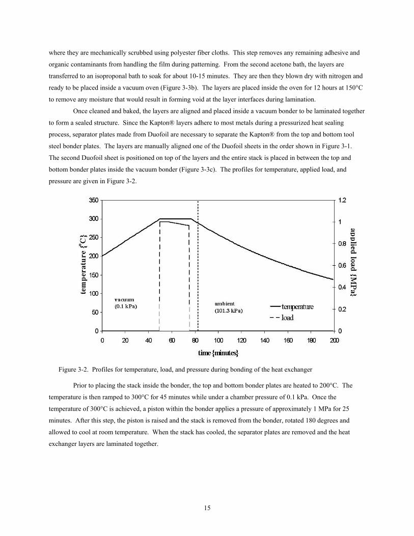
Figure 3-2. Profiles for temperature, load, and pressure during bonding of the heat exchanger
Prior to placing the stack inside the bonder, the top and bottom bonder plates are heated to 200°C. The
temperature is then ramped to 300°C for 45 minutes while under a chamber pressure of 0.1 kPa. Once the
temperature of 300°C is achieved, a piston within the bonder applies a pressure of approximately 1 MPa for 25
minutes. After this step, the piston is raised and the stack is removed from the bonder, rotated 180 degrees and
allowed to cool at room temperature. When the stack has cooled, the separator plates are removed and the heat
exchanger layers are laminated together.

16
Figure 3-3. Heat exchanger fabrication equipment (a) tangential knife cutter (b) vacuum oven (c) inside bonder chamber with stack between top and bottom bonder plates
3.2 Embedded connector Three different methods were considered in manufacturing the embedded connector. The first was to make
the connector by welding a 0.125 in OD stainless steel tubing to a 50 micron thick stainless steel sheet cut to the
diameter of the base. Secondly, the connector could be machined from a bulk material such as stainless steel or
copper to the dimensions given in the drawing. Finally, instead of welding a separate piece of tubing to a sheet,
electroplating the two together was considered using either nickel chloride or nickel sulfimate [31].
The welding method of manufacturing the embedded connector was attempted first. Stainless steel tubing
cut to 11 mm (the thickness of the top bonder plate) was welded to the 50 micron thick sheet of stainless steel base
as shown in Figure 3-4a. This method was not successful due to the weakness of the weld. During bonding, the
tube separated from the stainless steel base (shown in Figure 3-4b), causing failure of the connector and an unusable
heat exchanger.
Figure 3-4. (a) Stainless steel embedded connector made from welding tubing to base (b) Failure of weld during bonding
From this observation, machining the entire connector with tube and base from bulk material was attempted
next. The process starts with cutting a rod of raw material to a length of 15 mm, followed by machining the entire
length to the outer diameter of the base (8 mm). Next the tube region is machined to the outer diameter of 3.175 mm
(0.125 in). The remaining 4 mm of length of 8 mm diameter is machined down to the thickness of the base. Finally,
the inner diameter of 1.8 mm is drilled to complete the embedded connector.
Stainless steel was the first material chosen to machine, however difficulties arose with the 50 micron
thickness of the base. A softer and more ductile material, copper, was attempted next. The tube section did not
cause problems during machining; however the base due to the small thickness became difficult to machine. As the
(a) (b)
(a) (b) (c)
17
tool bit approached the base and machining down to a thickness of 50 µm, the base would separate from the tube,
causing the connector to be unusable. In order to correct this problem, the base was not machined down to 50 µm,
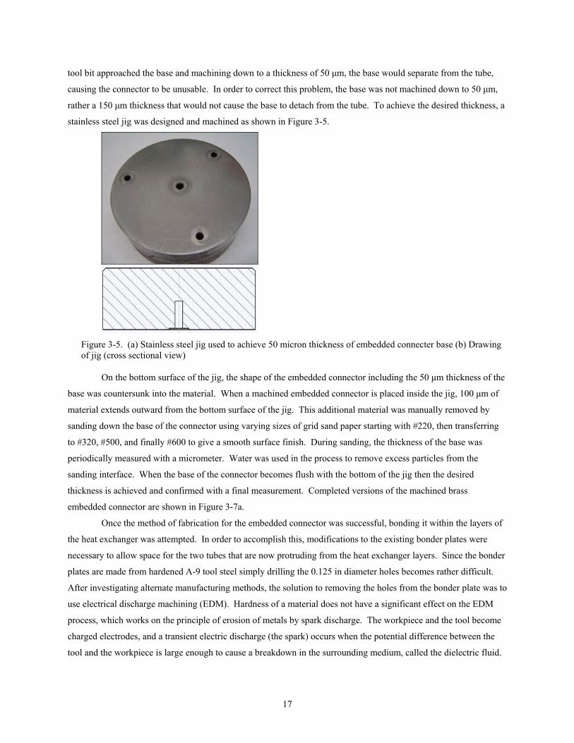
rather a 150 µm thickness that would not cause the base to detach from the tube. To achieve the desired thickness, a
stainless steel jig was designed and machined as shown in Figure 3-5.
Figure 3-5. (a) Stainless steel jig used to achieve 50 micron thickness of embedded connecter base (b) Drawing of jig (cross sectional view)
On the bottom surface of the jig, the shape of the embedded connector including the 50 µm thickness of the
base was countersunk into the material. When a machined embedded connector is placed inside the jig, 100 µm of
material extends outward from the bottom surface of the jig. This additional material was manually removed by
sanding down the base of the connector using varying sizes of grid sand paper starting with #220, then transferring
to #320, #500, and finally #600 to give a smooth surface finish. During sanding, the thickness of the base was
periodically measured with a micrometer. Water was used in the process to remove excess particles from the
sanding interface. When the base of the connector becomes flush with the bottom of the jig then the desired
thickness is achieved and confirmed with a final measurement. Completed versions of the machined brass
embedded connector are shown in Figure 3-7a.
Once the method of fabrication for the embedded connector was successful, bonding it within the layers of
the heat exchanger was attempted. In order to accomplish this, modifications to the existing bonder plates were
necessary to allow space for the two tubes that are now protruding from the heat exchanger layers. Since the bonder
plates are made from hardened A-9 tool steel simply drilling the 0.125 in diameter holes becomes rather difficult.
After investigating alternate manufacturing methods, the solution to removing the holes from the bonder plate was to
use electrical discharge machining (EDM). Hardness of a material does not have a significant effect on the EDM
process, which works on the principle of erosion of metals by spark discharge. The workpiece and the tool become
charged electrodes, and a transient electric discharge (the spark) occurs when the potential difference between the
tool and the workpiece is large enough to cause a breakdown in the surrounding medium, called the dielectric fluid.

18
The discharge occurs very rapidly and removes the metal a small amount each time [26]. The modified top bonder
plate is shown in Figure 3-6with the two embedded connector holes spaced 47.5 mm apart (center to center).
Figure 3-6. Modified top bonder plate for bonding embedded connector within heat exchanger layers
The final modification to the bonding process involved drilling two holes in the Duofoil separator sheets to
also allow the tube section of the embedded connector to protrude from the layers of the heat exchanger. The final
consideration was to machine the piece from bulk material. As a result of these modifications, the embedded
connector will not interfere with the bonder plate and cause a difference in the overall thickness during the bonding
process. A laminated heat exchanger with two brass embedded connectors is shown in Figure 3-7b ready to be
connected to tubing using compressing fittings.
Figure 3-7. Machined brass embedded connector (a) close-up (b) laminated within heat exchanger layers and ready for compression fittings
3.3 Snap-in and wedge connector The fabrication method chosen for the snap-in and wedge connector is a common rapid prototyping
technique called stereolithography. The reasons this method were chosen include availability, decreased build
times, increased number of iterations that can be tested, and material considered as a model for a polymer connector
[27]. Since the design schemes for both the snap-in and wedge connectors are similar, the same manufacturing
technique was chosen to build both designs.
(a) (b)

19
3.3.1 The stereolithography process The stereolithography apparatus (SLA) is a widely used rapid prototyping tool that can build a solid, plastic
prototype from a computer solid model in a matter of hours. The SLA machine consists of four major parts: a
square container holding an ultraviolet sensitive photopolymer liquid (resin), a platform located inside the container
to hold the parts during the building process, a UV laser located above the platform, and a computer that controls the
laser and the platform as shown in Figure 3-8 [27-29].
Figure 3-8. (a) Stereolithography Apparatus (b) close-up of build platform and resin container inside the SLA chamber
The process begins by drawing a three dimensional solid model on any CAD software (SolidWorks used
for this project) and saved as a “.stl” file extension. The stl file is transferred to another computer program, 3-D
Lightyear, where the parts are arranged on the platform in the desired position during building. The program
automatically generates support structures between the parts and the platform to ensure stability during building.
Support structures are only used for the fabrication of the parts and are discarded after the build is complete. The
program also converts the solid model into vertical slices about 10 layers per millimeter of height that can be
recognized by the SLA computer.
When the slice files are loaded on the SLA machine, the computer controls the laser to write the cross-
section of the first layer on the platform. The platform then lowers by the height of the next layer into the container
of resin, and the next layer is written by the laser. This process of writing and lowering of platform repeats until the
parts are complete and each layer is built. Once the build is complete, the parts are removed from the supports and
the platform, cleaned with acetone to remove access resin, and then placed inside a UV oven for final curing.
Since SLA is a layering process, stair steps are generated on the sides of parts. Thus, the build orientation
is an important consideration. The sides of parts contain steps and ridges while the top of piece remains very
smooth. In contrast to the smooth top surface, the bottom surface contains small bumps from the contact areas of
the supports. The side and bottom surface are typically sanded down to achieve a smoother finish. However,
depending on the surfaces that are sanded, the dimensions of the part can be slightly altered. To compensate for this,
dimensions of surfaces to be sanded are slightly increased (~0.1mm) in the design.
Resin Container
Laser Build
Platform
(a) (b)

20
3.3.2 Snap-in connector In building the two pieces of the snap-in connector, different build orientations were tested to determine the
best surface finish of the completed parts. First, top and bottom pieces were built with the bottom surface in contact
with the supports. After building, the top piece was observed to have a rough surface finish on the bottom where
the o-ring is housed. As for the bottom piece, the matting surface that comes into contact with the o-ring had a
smooth surface finish. From these observations, the top piece was inverted so that the bottom surface (housing the
o-ring) was not in contact with the supports and resulted in a smooth surface finish. A final building test positioned
the top and bottom pieces with the side surfaces in contact with the support structures. This resulted in poor
resolution of the circular areas of the top piece including the tube region and the o-ring region. Since the tube region
and the o-ring housing were built on the side, the stair step associated with the SLA machine affected the
smoothness of the circles. As a result of these tests, the best method for part placement of the top piece was to have
the o-ring surface as the top surface and for the bottom piece to have the bottom surface in contact with the support
structures as shown in Figure 3-9.
Figure 3-9. Snap-in connector with supports on the SLA platform in 3-D Lightyear (a) original design (b) design with decreased dimensions
Photographs of the fabricated snap-in connector are shown in Figure 3-10 with assembled view attached to
a heat exchanger, disassembled with top piece housing an o-ring, and a secondary design with decreased overall
height. During repeated assembly and disassembly of the snap-in connector, the sides of the bottom piece began to
separate from the base at the bottom corner (as seen in Figure 3-10e). This failure occurred more frequently in the
designs with the decreased height. The inherent pulling apart of the bottom piece sides to disassemble the snap-in
connector became a source of failure. As a result of this observation, a different sealing method was considered and
led to the idea of using the wedge design.
(a) (b)
21
Figure 3-10. Snap-in connector (a) assembled with heat exchanger (b) top and bottom piece separated (c) original design assembled (d) smaller version assembled (e) common failure point (circled) of bottom piece
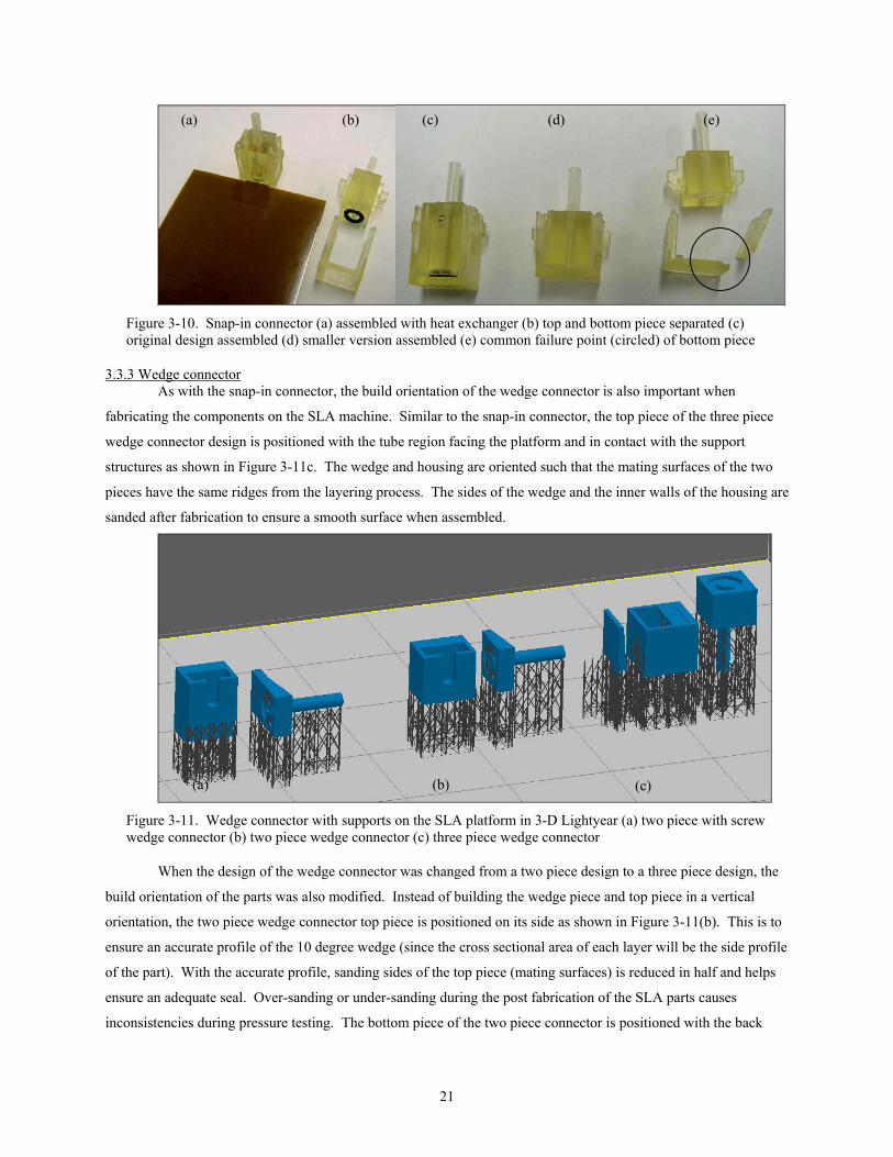
3.3.3 Wedge connector As with the snap-in connector, the build orientation of the wedge connector is also important when
fabricating the components on the SLA machine. Similar to the snap-in connector, the top piece of the three piece
wedge connector design is positioned with the tube region facing the platform and in contact with the support
structures as shown in Figure 3-11c. The wedge and housing are oriented such that the mating surfaces of the two
pieces have the same ridges from the layering process. The sides of the wedge and the inner walls of the housing are
sanded after fabrication to ensure a smooth surface when assembled.
Figure 3-11. Wedge connector with supports on the SLA platform in 3-D Lightyear (a) two piece with screw wedge connector (b) two piece wedge connector (c) three piece wedge connector
When the design of the wedge connector was changed from a two piece design to a three piece design, the
build orientation of the parts was also modified. Instead of building the wedge piece and top piece in a vertical
orientation, the two piece wedge connector top piece is positioned on its side as shown in Figure 3-11(b). This is to
ensure an accurate profile of the 10 degree wedge (since the cross sectional area of each layer will be the side profile
of the part). With the accurate profile, sanding sides of the top piece (mating surfaces) is reduced in half and helps
ensure an adequate seal. Over-sanding or under-sanding during the post fabrication of the SLA parts causes
inconsistencies during pressure testing. The bottom piece of the two piece connector is positioned with the back
(a) (b) (c) (d) (e)
(a) (b) (c)

22
surface in contact with the supports. If the bottom piece was placed on its side like the top piece, supports would be
necessary inside the part. Having supports along the inner walls of the bottom piece would require sanding to
achieve a smooth surface finish when assembling the two pieces together. Sanding the inner walls of the bottom
piece is avoided since they are difficult to reach with the current sanding tools. The tools used for post fabrication
of the SLA parts include different grit size sandpaper, an X-acto® knife, and emory boards.
Photographs of the fabricated wedge connectors are shown in Figure 3-12 for the three piece connector
(shown with single channel test heat exchanger), Figure 3-13 for the two piece design, and Figure 3-14 for the two
piece with screw design. As shown, all three designs of the wedge connector can be connected to standard tubing
and piping using compression fittings. The choice of using the stereolithography process was beneficial in
fabricating the many different designs and iterations of the snap-in and wedge connectors.
Figure 3-12. Three piece wedge connector shown with single channel test heat exchanger (a) exploded view (b) assembled view
(a) (b)
23
Figure 3-13. Two piece wedge connector (a) top and bottom pieces disassembled (b) fully assembled with heat exchanger and compression fittings
Figure 3-14. Screw two-piece wedge connector (a) top and bottom piece with o-ring (b) fully assembled with screw, compression fitting, and heat exchanger
As shown in the previous chapter, the design of the wedge connector can be transferred from connecting to
tubing and piping to connecting the heat exchanger in series and in parallel. The same manufacturing method used
for the wedge connector, stereolithography, was used in fabricating the series and parallel connector. The main
housing block containing the o-rings and internal piping structure and the multi-wedge structure are shown in Figure
3-15 in both disassembled view (left) and fully assembled view (right) with two connectors on both inlet and outlet
(a)
(b)
(a) (b)
24
side of three heat exchangers. As shown, this connection can attach to standard 0.25 in outer diameter compression
fittings.
Figure 3-15. Wedge connector used for connecting heat exchangers in series and parallel (a) housing and multi-wedge structure disassembled (b) fully assembled with three heat exchangers connected in parallel
Although the figure shows the multi-wedge structure with three wedge segments attached together,
individual wedge segments can be used for sealing each heat exchanger against the o-rings. Also, it should be noted
a three level parallel connection is shown in the figure, more levels are possible and can be manufactured in the
future. Future testing could include determining the relationship between pressure drop and the number of levels,
the effective heat transfer of a cross flow, and the effects of spacing between the levels on the heat transfer
capability.
3.4 Thermally bonded connector The manufacturing method for the thermally bonded connector is rather straightforward as it follows the
same procedure given for fabricating the heat exchanger. Test size heat exchangers were fabricated first to
demonstrate the ability for the connection method to properly seal and convey fluid. Once tests were conducted on
the test size, full size thermally bonded connector heat exchanger were fabricated and bonded together.
The test size heat exchangers consisted of three layers: (1) inlet and outlet, (2) single channel, (3) cap. Two
test size heat exchangers were laminated separately during a single run and are shown in Figure 3-16. Afterwards,
the test size heat exchangers were repositioned within the bonder, with the inlet of one test size Hex directly aligned
on top of the outlet of the second test size Hex and the KJ spacer layer in between them.
Figure 3-16. Test size thermally bonded heat exchanger
(a) (b)

25
During the second lamination two additional Duofoil separator plates were used inside the standard Duofoil
sheets to isolate the 20 mm diameter of overlapping area. The inner Duofoil sheets were cut to the 20 mm diameter
while the outer sheets remained the same size (150 mm by 150 mm). The stacked placed in between the bonder
plates consists of (in order from bottom to top): outer square Duofoil sheet, inner circular Duofoil sheet, first Hex
with outlet facing upward, spacer layer, second Hex with inlet facing downwards, second inner circular Duofoil
sheet, and second outer square Duofoil sheet. The only change to the bonding procedure was the reduction in force
applied by the piston to compensate for the decreased area. To achieve the required 1 MPa of applied pressure to
laminate, the 60 mm by 60 mm heat exchanger requires 3600 N of force. This is reduced to 315 N for the thermally
bonded connection of area 315 mm2. Photographs of the full size thermally bonded connection heat exchangers are
shown in Figure 3-17.
Figure 3-17. Full size thermally bonded connection (a) close-up of overlapping region (b) two heat exchangers bonded together
(a) (b)

26
Chapter 4. Testing of Interconnects and Heat Exchanger
Once the interconnects were designed and manufactured, they were ready to be tested. Based on the
literature review of other micro-to-macro interconnects presented in Chapter 1, two types of testing were performed.
The first test determines the maximum pressure the connector can withstand before leakage. The second test
determines the amount of pull-out force needed to separate the connector from the heat exchanger. The results are
presented with a comparison to other connectors described earlier. Finally, fatigue testing for the heat exchangers is
presented with a stress versus number of cycles to failure (S-N) graph.
4.1 Pressure testing of interconnects 4.1.1 Experimental setup
The pressure test, or leakage pressure test, was performed for all interconnect designs. The first connector
manufactured was the snap-in connector, thus it was the first to be pressure tested. The first pressure test setup was
simply attaching the snap-in connector to a compression fitting and then connecting to a compressed air line. A
single channel test heat exchanger (three layers, 30 mm long and 10 mm wide) with an inlet and outlet was used.
The snap-in connector was attached to the inlet and submerged into a bath of water while connected the compressed
air line. With air flowing, if bubbles appeared from the outlet hole and not from the vicinity of the connector, it was
determined it was successful in conveying the fluid to the outlet and not leaking around the inlet and connector.
For the remainder of the connectors designed and developed, a different pressure test setup was constructed
to accommodate higher pressures using compressed nitrogen. The heat exchanger with connectors attached to the
inlet and outlet is placed inside a water bath with pressure gauges on both ends. Nitrogen is supplied from a
cylinder and controlled using a needle valve. The pressure is increased until failure occurs as indicated by bubbles
forming in the water bath due to leakage. A schematic for the test setup is shown in Figure 4-1 and the actual setup
is shown in Figure 4-2.
Figure 4-1. Schematic of pressure test setup
In constructing the pressure test setup, 0.25 in stainless steel tubing was used for the piping, standard 0.25
in compression fittings were used at the junctions and a reduction coupling was used to join the 0.125 in
compression fittings attached to the connectors.
27
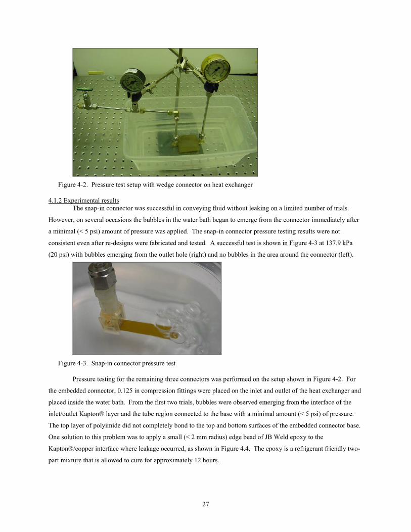
Figure 4-2. Pressure test setup with wedge connector on heat exchanger
4.1.2 Experimental results The snap-in connector was successful in conveying fluid without leaking on a limited number of trials.
However, on several occasions the bubbles in the water bath began to emerge from the connector immediately after
a minimal (< 5 psi) amount of pressure was applied. The snap-in connector pressure testing results were not
consistent even after re-designs were fabricated and tested. A successful test is shown in Figure 4-3 at 137.9 kPa
(20 psi) with bubbles emerging from the outlet hole (right) and no bubbles in the area around the connector (left).
Figure 4-3. Snap-in connector pressure test
Pressure testing for the remaining three connectors was performed on the setup shown in Figure 4-2. For
the embedded connector, 0.125 in compression fittings were placed on the inlet and outlet of the heat exchanger and
placed inside the water bath. From the first two trials, bubbles were observed emerging from the interface of the
inlet/outlet Kapton® layer and the tube region connected to the base with a minimal amount (< 5 psi) of pressure.
The top layer of polyimide did not completely bond to the top and bottom surfaces of the embedded connector base.
One solution to this problem was to apply a small (< 2 mm radius) edge bead of JB Weld epoxy to the
Kapton®/copper interface where leakage occurred, as shown in Figure 4.4. The epoxy is a refrigerant friendly two-
part mixture that is allowed to cure for approximately 12 hours.

28
Figure 4-4. Close-up of embedded connector edge bead
After curing, the compression fittings were once again attached and the embedded connector heat
exchanger was tested. With the edge bead present, the connectors were able to withstand pressure from 0.69-1.03
MPa (100-150 psi) with an average of 0.83 MPa (120 psi). Failure occurred when either the top or bottom layer of
the heat exchanger began to delaminate. The delamination began in the area of the embedded connector and quickly
propagated throughout the channels and eventually to the edges of the pressurized heat exchanger. Figure 4-5 shows
the failure while submerged in the water bath (a) and the delamination after being removed from the setup (b).
Figure 4-5. Embedded connector pressure test failure (a) inside water bath (b) delamination of heat exchanger inlet/outlet layer
The wedge connector was pressure tested in a similar manner as the embedded connector. Two connectors
with compression fittings were placed on the inlet and outlet of an extended heat exchanger, connected to the setup,
and submerged in the water bath. The pressure when leakage began ranged from 1.72 MPa (250 psi) to 2.07 MPa
(300 psi) with an average of 1.83 MPa (266 psi). Bubbles were observed emerging from the interface between the
bottom surface of the top piece and the top surface of the Hex, as shown in Figure 4-6. As the distribution channels
leaving the inlet become pressurized, the outer layer of the Kapton® begins to bow upward above the channels.
This effect causes an uneven distribution of force acting on the o-ring and leads to leakage. A potential solution for
increasing the amount of pressure able to withstand is to use a more compliant material for the o-ring that will
conform to the rippled shape of the top layer as the channels become pressurized.
(a) (b)
29
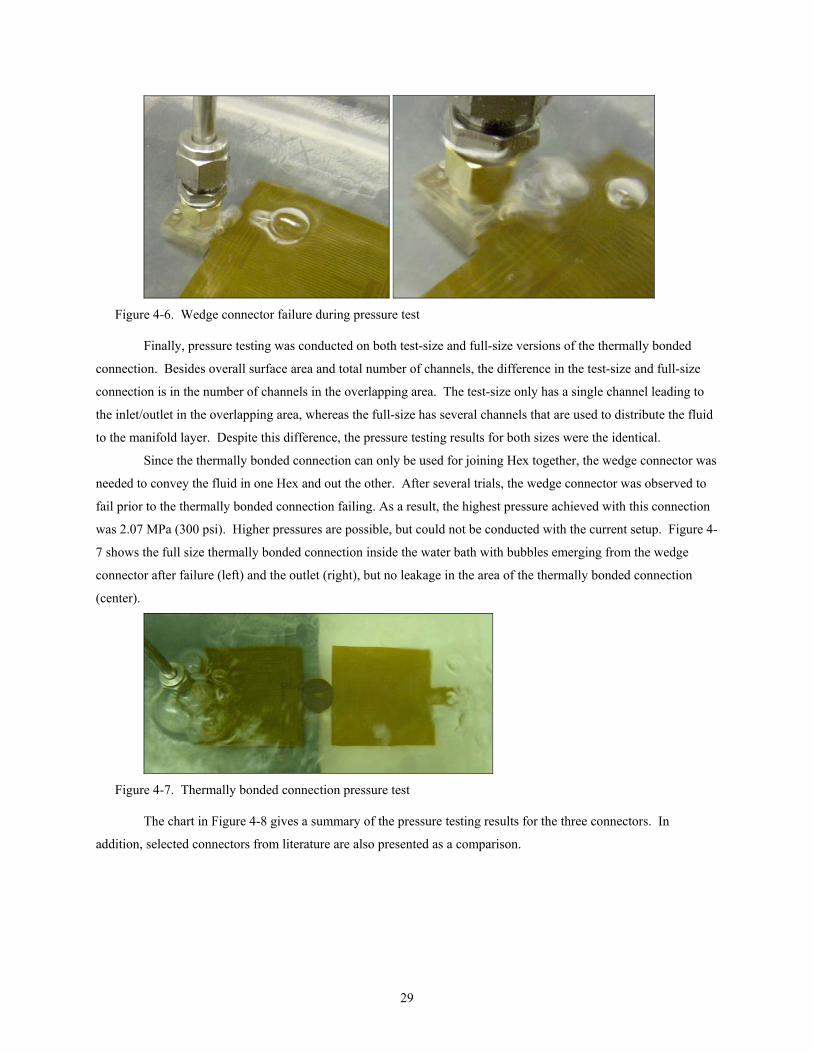
Figure 4-6. Wedge connector failure during pressure test
Finally, pressure testing was conducted on both test-size and full-size versions of the thermally bonded
connection. Besides overall surface area and total number of channels, the difference in the test-size and full-size
connection is in the number of channels in the overlapping area. The test-size only has a single channel leading to
the inlet/outlet in the overlapping area, whereas the full-size has several channels that are used to distribute the fluid
to the manifold layer. Despite this difference, the pressure testing results for both sizes were the identical.
Since the thermally bonded connection can only be used for joining Hex together, the wedge connector was
needed to convey the fluid in one Hex and out the other. After several trials, the wedge connector was observed to
fail prior to the thermally bonded connection failing. As a result, the highest pressure achieved with this connection
was 2.07 MPa (300 psi). Higher pressures are possible, but could not be conducted with the current setup. Figure 4-
7 shows the full size thermally bonded connection inside the water bath with bubbles emerging from the wedge
connector after failure (left) and the outlet (right), but no leakage in the area of the thermally bonded connection
(center).
Figure 4-7. Thermally bonded connection pressure test
The chart in Figure 4-8 gives a summary of the pressure testing results for the three connectors. In
addition, selected connectors from literature are also presented as a comparison.
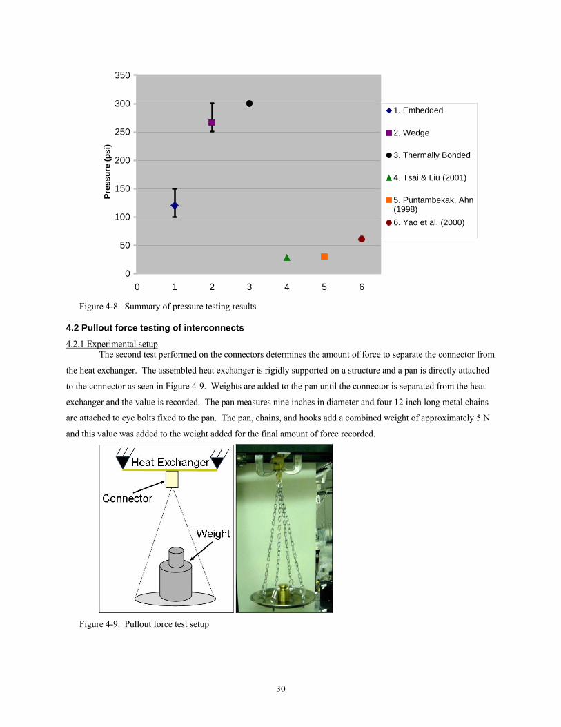
30
0
50
100
150
200
250
300
350
0 1 2 3 4 5 6
Pres
sure
(psi
)1. Embedded
2. Wedge
3. Thermally Bonded
4. Tsai & Liu (2001)
5. Puntambekak, Ahn(1998)6. Yao et al. (2000)
Figure 4-8. Summary of pressure testing results
4.2 Pullout force testing of interconnects
4.2.1 Experimental setup The second test performed on the connectors determines the amount of force to separate the connector from
the heat exchanger. The assembled heat exchanger is rigidly supported on a structure and a pan is directly attached
to the connector as seen in Figure 4-9. Weights are added to the pan until the connector is separated from the heat
exchanger and the value is recorded. The pan measures nine inches in diameter and four 12 inch long metal chains
are attached to eye bolts fixed to the pan. The pan, chains, and hooks add a combined weight of approximately 5 N
and this value was added to the weight added for the final amount of force recorded.
Figure 4-9. Pullout force test setup

31
Since the embedded connector and the wedge connector are different in design and heat exchanger
orientation, different setups were required. The wedge connector pullout force setup is shown in Figure 4-10a and
the embedded connector setup is shown in Figure 4-10b.
Figure 4-10. Close-up of pullout force test (a) wedge connector (b) embedded connector
For the embedded connector, a metal plate (25 mm by 10 mm by 3 mm) with a 0.125 in diameter hole
drilled in the center is placed around the tube section between the heat exchanger and the compression fitting as
shown in Figure 4-11. The compression fitting then screws into a structure with an inverted U-bolt used to hold the
chains via s-hooks. The purpose of the plate is to isolate the tube region during the pullout force test. Since the heat
exchanger with embedded connector remains flexible, the results of the test would predict a higher force than tests
without the isolation plate. This scenario gives the lowest possible load necessary to detach the embedded connector
from the heat exchanger.
Figure 4-11. Metal plate used to isolate tube section during pullout force test
The fixed housing structure shown in Figure 4-10a is used hold the top and bottom of the wedge connector
in place while the weights add force on the heat exchanger to separate it from the connection. The extended heat
exchanger is cut in half (to 30 mm in length) and five 0-80 socket cap screws affix it to a structure used to attach the
chains via s-hooks as shown in Figure 4-12. The heat exchanger and hook structure add a minimal amount (0.14 N)
of added force to the final recorded value.

32
Figure 4-12. Wedge with screw connector pullout force testing setup
In testing the wedge connector and the embedded connector, 50 g (0.5 N) increments of weight were added
to the pan until failure occurred.
4.2.2 Experimental results The embedded connector failed in the pullout force test in the range of 58.5 N to 72 N with an average of
65.5 N. The tube separated from the base that is embedded within the heat exchanger layers as shown in Figure 4-
13. As desired, the tube section was isolated from the flexible Kapton® layers and the recorded value of force
reflects that of the connector and not the heat exchanger.
Figure 4-13. Embedded connector failure after pullout force test
Unlike the pressure test, the wedge with screw connector had a significant difference in results than the
wedge connector without the screw. The wedge connector without the screw failed at range from 21.6 N to 23.6 N
with an average of 22.5 N. The friction between the heat exchanger and the o-ring and bottom SLA piece is the only
resistance to pullout force. However, in the wedge with screw connector, the screw is placed through both pieces of
SLA and though the extended region of the Hex. The pullout force results ranged from 69.1 N to 78.1 N with an
average of 73.6 N. The failure for a typical wedge with screw heat exchanger is shown in Figure 4-14.

33
Figure 4-14. Wedge with screw connector failure after pullout force test
As the force increased, the screw provided resistance from the heat exchanger pulling out until the
Kapton® ripped at an approximate angle of 45 degrees from the centerline of the screw hole. The pullout force
results are summarized in the graph of Figure 4-15 and compared to other selected connectors presented in Chapter
1.
0
10
20
30
40
50
60
70
80
90
0 1 2 3 4 5 6
Forc
e (N
)
1. Embedded
2. Wedge
3. Wedge withscrew
4. Tsai and Liu(2001)
5. Puntambekar,Ahn (1998)
6. Yao et al. (2000)
Figure 4-15. Pullout force testing results
After extensive handling of the wedge connector, failure began to occur in the tube section of the tube piece
as shown in Figure 4-16. A common method of disassembly for the wedge connector is to hold the bottom piece
secure while pulling the top piece out by grabbing the compression fitting. Since the wedge connectors used here
are prototypes made from SLA, the amount of force the tube section can withstand is limited.
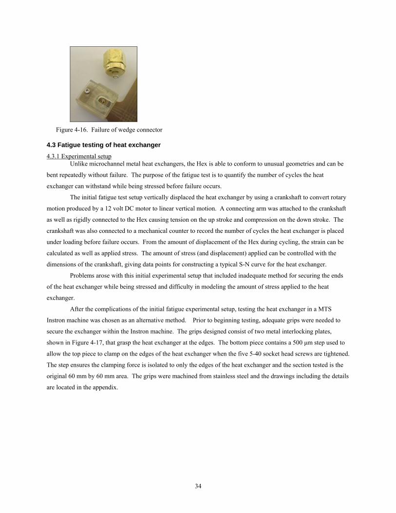
34
Figure 4-16. Failure of wedge connector
4.3 Fatigue testing of heat exchanger
4.3.1 Experimental setup Unlike microchannel metal heat exchangers, the Hex is able to conform to unusual geometries and can be
bent repeatedly without failure. The purpose of the fatigue test is to quantify the number of cycles the heat
exchanger can withstand while being stressed before failure occurs.
The initial fatigue test setup vertically displaced the heat exchanger by using a crankshaft to convert rotary
motion produced by a 12 volt DC motor to linear vertical motion. A connecting arm was attached to the crankshaft
as well as rigidly connected to the Hex causing tension on the up stroke and compression on the down stroke. The
crankshaft was also connected to a mechanical counter to record the number of cycles the heat exchanger is placed
under loading before failure occurs. From the amount of displacement of the Hex during cycling, the strain can be
calculated as well as applied stress. The amount of stress (and displacement) applied can be controlled with the
dimensions of the crankshaft, giving data points for constructing a typical S-N curve for the heat exchanger.
Problems arose with this initial experimental setup that included inadequate method for securing the ends
of the heat exchanger while being stressed and difficulty in modeling the amount of stress applied to the heat
exchanger.
After the complications of the initial fatigue experimental setup, testing the heat exchanger in a MTS
Instron machine was chosen as an alternative method. Prior to beginning testing, adequate grips were needed to
secure the exchanger within the Instron machine. The grips designed consist of two metal interlocking plates,
shown in Figure 4-17, that grasp the heat exchanger at the edges. The bottom piece contains a 500 µm step used to
allow the top piece to clamp on the edges of the heat exchanger when the five 5-40 socket head screws are tightened.
The step ensures the clamping force is isolated to only the edges of the heat exchanger and the section tested is the
original 60 mm by 60 mm area. The grips were machined from stainless steel and the drawings including the details
are located in the appendix.

35
Figure 4-17. Design of grips used in fatigue testing (a) exploded view (b) side view of assembled grip
The sides of the heat exchanger were extended to match the design of the grips as shown in Figure 4-17.
The extended area is 20 mm long and 60 mm wide, with five 4 mm diameter holes to prevent interference of the
screws while clamping together the two pieces of the grips.
An assembled fatigue heat exchanger with grips on the top and bottom placed inside the Instron machine is
shown in Figure 4-19. For the current configuration presented and shown, the heat exchanger is cyclically loaded
with the channels in the horizontal direction. Designs for the grips and respective heat exchanger were also
developed for cyclically loading the channels in the vertical direction. The detailed drawings for this configuration
are also provided in the appendix.
Figure 4-18. Fatigue wedge heat exchangers (a) wireframe drawing (b) fabricated
The design of the fatigue heat exchanger includes an inlet (but no outlet) for adding pressure using a wedge
connector during cyclic testing. S-N curves can be developed for different amounts of pressure held by the heat
exchanger while being cyclically loaded.
Bottom Piece
Top Piece
(a) (b)
(a) (b)
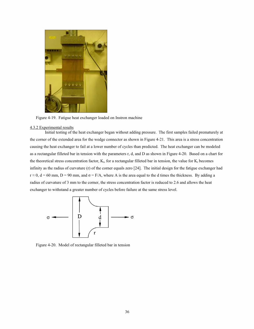
36
Figure 4-19. Fatigue heat exchanger loaded on Instron machine
4.3.2 Experimental results Initial testing of the heat exchanger began without adding pressure. The first samples failed prematurely at
the corner of the extended area for the wedge connector as shown in Figure 4-21. This area is a stress concentration
causing the heat exchanger to fail at a lower number of cycles than predicted. The heat exchanger can be modeled
as a rectangular filleted bar in tension with the parameters r, d, and D as shown in Figure 4-20. Based on a chart for
the theoretical stress concentration factor, Kt, for a rectangular filleted bar in tension, the value for Kt becomes
infinity as the radius of curvature (r) of the corner equals zero [24]. The initial design for the fatigue exchanger had
r ≈ 0, d = 60 mm, D = 90 mm, and σ = F/A, where A is the area equal to the d times the thickness. By adding a
radius of curvature of 3 mm to the corner, the stress concentration factor is reduced to 2.6 and allows the heat
exchanger to withstand a greater number of cycles before failure at the same stress level.
Figure 4-20. Model of rectangular filleted bar in tension

37
Figure 4-21. Failure of fatigue heat exchanger with sharp corners
After the radius of the corner was increased, the heat exchanger was able to withstand a greater number of
cycles before failure. Two common places in which failure began are shown in Figure 4-22. The onset of failure for
the heat exchanger on the left began at the left edge of the top most channel. Since the top (and bottom) channels
are have greater lengths than the center channels, the cross-sectional areas of these regions are less and a source for
failure to begin. The onset of failure for the heat exchanger on the right of the figure is once again at the stress
concentration of the corner. However, in the case of the rounded corner, the heat exchanger is able to be under a
cyclic load for a greater number of cycles than without the radius. A summary of successful heat exchangers
cyclically tested (without being pressurized) is provided in a S-N diagram in Figure 4-23 on a log-log scale.
Figure 4-22. Failure of fatigue heat exchanger with rounded corners
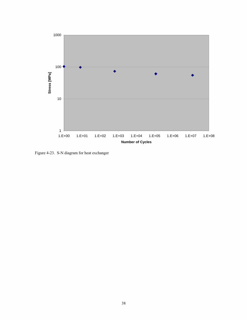
38
1
10
100
1000
1.E+00 1.E+01 1.E+02 1.E+03 1.E+04 1.E+05 1.E+06 1.E+07 1.E+08
Number of Cycles
Stre
ss [M
Pa]
Figure 4-23. S-N diagram for heat exchanger

39
Chapter 5. Conclusions and Recommendations
5.1 Conclusions The report has presented four uniquely different connection methods for non-metallic, flexible, thin,
microchannel heat exchangers that were designed, manufactured, and tested. Two types of testing common to
micro-to-macro connectors were conducted including pressure leakage testing and pullout force testing. With these
function prototype connectors, the heat exchanger is now able to connect to piping and tubing using compression
fittings and also connecting multiple heat exchangers together in series of parallel. In addition to the connector
results, the heat exchanger was also subjected to cyclic loading to determine the number of cycles to failure.
The first connector developed was an internal type placed within the layers of the heat exchanger during
bonding referred to as the embedded connector. The connector is machined from bulk copper and contains two
main sections: the tube and the base. The tube has an outer diameter of 0.125 in used for compression fittings and
the base has a thickness of 50 µm to match the thickness of individual layers. The testing results for the embedded
connector show a range of 0.69 to 1.03 MPa (100 to 150 psi) can be held before leaking and 58.5 N to 72 N before
separation occurs with the heat exchanger.
The second connector developed was an external type placed around the inlet and outlet holes of a modified
heat exchanger called the snap-in connector. The connector was manufactured using stereolithography, consisted of
a two-piece design that snapped together, and used an o-ring for sealing. Preliminary pressure testing of this
connector resulted in inconsistent results and premature failure of the bottom piece due to handling.
From the results of the snap-in connector, a similar external connector made from SLA was developed with
a different sealing method. This connector used a wedge placed between the bottom surface of the heat exchanger
to provide a sealing force against an o-ring positioned within the top piece. The wedge connector began leaking at
pressures between 1.72 MPa (250 psi) to 2.07 MPa (300 psi) and separated at forces between 21.6 N and 23.6 N for
the connector without a screw and 69.1 N to 78.1 N for connectors with a screw. In addition to connecting to piping
and tubing, the wedge method of sealing was used in connecting multiple heat exchangers together in series and
parallel. This design was also developed and pressure tested with results similar to the connector for tubing and
piping.
The final connection method developed was also an external type that directly laminated the inlet of one
heat exchanger to the outlet of another, referred to as the thermally bonded connector. One of the main advantages
of this design is that no additional parts are necessary. In addition, pressure test results show the highest pressure
held amongst all connectors tested with the ability to hold more than 2.07 MPa (300 psi) under the current test setup.
However, the thermally bonded connector is limited to connecting heat exchangers together, but not to external
piping and tubing.
After the connection methods were developed and tested, the heat exchanger was subjected to cyclic
loading using an Instron machine. The heat exchanger was positioned such that the channels were in a horizontal
direction and a typical S-N diagram was established for a zero pressure scenario.

40
5.2 Recommendations The connection methods described earlier are essentially working prototypes that require further
development before transitioning to mass production. Several recommendations for the connector and future tests
for the heat exchanger are highlighted here:
• The embedded connector fabrication method can be transferred to a mass production process such
as stamping to reduce time and cost of manufacturing. Also, improvements need to be made on the
adhesion of copper to Kapton® to eliminate the need for the edge bead. The optimal diameter of
the base with respect to bonding strength to the Kapton® can also be determined.
• The wedge connector fabrication method can also be transferred to a mass production process such
as injection molding, using a refrigerant friendly polymer. Also, additional materials used for the
o-ring can be explored to provide more compliance as the heat exchanger reaches pressures above
1.72 MPa (250 psi).
• Improvements for the thermally bonded connection can be made in determining the optimal
diameter of the overlapping area. Pullout force testing needs to be conducted on the thermally
bonded connection and correlated to the overlapping area.
• Further testing needs to be conducted on the heat exchanger as well, including fatigue testing
using pressurized heat exchangers. S-N curves can be established for different amounts of
pressure and an analysis of failure should also be conducted. In addition, fatigue testing with the
channels in the vertical direction should be done similar to the channels in the horizontal direction.
• Other types of testing for the heat exchanger can include (1) determining the amount of diffusion
for refrigerants (such as butane, R134a, R410a), non-condensable gases in air, and water across
the outer layers, and (2) determining the effective thermal conductivity of heat exchanger as a
function of wall thickness, channel spacing, and channel width, with a comparison to metal
microchannel heat exchangers.

41
References
1. Philpott, M. L. and M. A. Shannon. “Non-metallic, flexible, thin, multichannel heat exchangers for refrigeration and air-conditioning applications”, Proposal to the Air-Conditioning and Refrigeration Center (ACRC), April 2002.
2. Burns, J. R. and R. J. J. Jachuck. “Condensation studies using cross-corrugated polymer film compact heat exchanger”, Applied Thermal Engineering, Vol. 21, pp. 495-510, 2001.
3. Martin, P. M., W. D. Bennett, and J. W. Johnston. "Microchannel heat exchangers for advanced climate control", Proceedings of the SPIE, Vol. 2639, pp. 82-88, 1995.
4. Cartwright, J. R. “Prototype design of an integrated mesoscopic cooler circuit (IMCC) system”, M.S. Thesis, University of Illinois at Urbana-Champaign, 1998.
5. Delphi Automotive Systems, Troy, MI. Modine Manufacturing Co., Racine, WI.
6. Mangriotis, M. D., S. S. Mehendale, T. Z. Liu, A. M. Jacobi, M. A. Shannon, and D. J. Beebe. “Flexible microfluidic polyimide channels”, Transducers 99, The 10th International Conference on Solid-State Sensors and Actuators, Digest of Technical Papers, Sendai, Japan, pp. 772-775, June 7-10, 1999.
7. Glasgow, I. K., D. J. Beebe, and V. E. White. “Design rules for polyimide solvent bonding”, Sensors and Materials, Vol. 11.5, pp. 269-278, 1999.
8. Selby, J. C., M. L. Philpott, and M. A. Shannon. “Fabrication of mesoscopic, flexible, high pressure, microchannel heat exchangers (MHEx)”, Transactions of NAMRI/SME, Vol. 29, May 22-25, 2001.
9. Shannon, M. A., M. L. Philpott, N. R. Miller, C. W. Bullard, D. J. Beebe, A. M. Jacobi, P. S. Hrnjak, T. A. Saif, N. Aluru, H. Sehitoglu, A. Rockett, and J. Economy. "Integrated mesoscopic cooler circuits (IMCCs)," Proceedings of the ASME, Advanced Energy System Division, Symposium on Miniature and Mesoscopic Energy Conversion Devices, Vol. 39, pp. 75-82, 1999.
10. Puntambekar, A. and C. Ahn. “Self-aligning microfluidic interconnects for glass and plastic based microfluidic systems”, Journal of Micromachining and Microengineering, Vol. 12, pp. 35-40, 1998.
11. Tsai, J. and L. Lin. “Micro-to-macro fluidic interconnectors with an integrated polymer sealant”, Journal of Micromachining and Microengineering, Vol. 11, pp. 577-581, 2001.
12. Pattekar, A. V. and M. V. Kothare. “Novel microfluidic interconnectors for high temperature and pressure applications”, Journal of Micromachining and Microengineering, Vol. 13, pp. 337-345, 2003.
13. Yao, T., S. Lee, W. Fang, and Y. Tai. “Micromachined rubber o-ring micro-fluidic couplers”, Proceedings of the IEEE MicroElectroMechanical Systems (MEMS), pp. 624-627, 2000.
14. Li, S. and S. Chen. “Polydimethylsioxane fluidic interconnects for microfluidic systems”, IEEE Transactions on Advanced Packaging, Vol. 26, No. 3, pp. 242-247, August 2003.
15. Armani, D., C. Liu, and N. Aluru. “Re-configurable fluid circuits by PDMS elastomer micromachining”, Proceedings of the IEEE MicroElectroMechanical Systems (MEMS), pp. 222-227, 1999.
16. Martin, P. M., D. W. Matson, W. D. Bennett, and D. J. Hammerstrom. “Fabrication of plastic microfluidic components”, SPIE Conference on Microfluidic Devices and Systems, Santa Clara, CA, pp. 172-176, September 1998.
17. Gonzalez, C., J. Y. Pan, S. D. Collins, and R. L. Smith. “Packaging technology for miniature IVD instrumentation”, Medical Device and Diagnostic Industry, Vol. 20, No. 4, pp. 70-75, April 1998.
18. VerLee D., A. Alcock, and G. Clark. “Fluid circuit technology: integrated interconnect technology for miniature fluidic devices”, Proceedings of Solid State Sensor and Actuator Workshop, Hilton Head Island, SC, pp. 9-14, 1996.
19. Jiang, Y., P. Wang, L. Lacascio, and C. Lee. “Integrated plastic microfluidic devices with ESI-MS for drug screening and residue analysis”, Analytical Chemistry, Vol. 73, pp. 2048-53, 2001.

42
20. Mourlas, N., D. Jaeggi, A. Flannery, B. Gray, B. van Drieehuizen, C. Storment, N. Maluf, and G. Kovacs. “Novel interconnection and channel technologies for microfluidics”, Proceedings of µTAS ’98 Workshop, pp. 27-30, 1998.
21. Man, P. F., D. K. Jones, and C. H. Mastrangelo. “Microfluidic plastic interconnects for multibioanalysis chip modules”, Proceedings of SPIE, Vol. 3224, pp. 196-201, 1997.
22. Han, J., Z. Tan, K. Sato, and M. Shikida. “Three-dimensional interconnect technology on a flexible polyimide film”, Journal of Micromechanics and Microengineering, Vol. 14, pp. 38-48, 2004.
23. Shigley, J. E. and C. R. Mischke. Mechanical Engineering Design, Fifth Ed., New York: McGraw-Hill, Inc., 1989.
24. Shigley, J. E. and C. R. Mischke. Standard Handbook of Machine Design, Second Ed., New York: McGraw-Hill, Inc., 1996.
25. Horowitz, P. and W. Hill. The Art of Electronics, Second Ed., New York: Cambridge University Press, 2001.
26. Avallone, E. A. and T. Baumeister. Marks’ Standard Handbook for Mechanical Engineers, Tenth Ed., New York: McGraw-Hill, Inc., 1996.
27. Rapid Prototyping: An Overview. Engineering Fundamentals, July 2003. www.efunda.com/processes/rapid_prototyping/intro.cfm
28. Instruction manual for the StereoLithography Apparatus (SLA-250), 2001.
29. How Stereolithography (3-D layering) Works. Howstuffworks.com, July 2003. http://computer.howstuffworks.com/stereolith.htm
30. Callister, W. D. Materials Science and Engineering an Introduction, Fifth Ed., New York: John Wiley & Sons, Inc., 2000.
31. Madou, M. Fundamentals of Microfabrication, First Ed., Boca Raton: CRC Press, 1997.

43
Appendix A – Engineering Drawings
--8 ---«
, " •• II II . I ' i' <! o • 0
o
I 110500 1 r---~
;
I
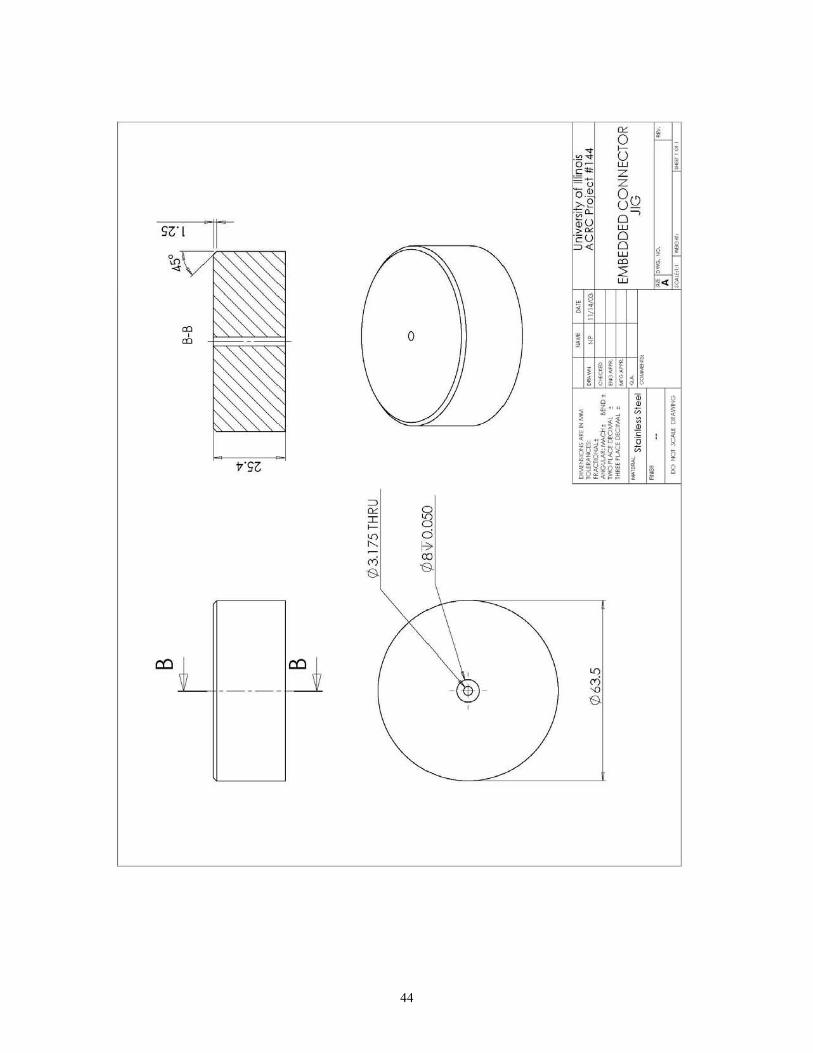
44
II
1'51:
=> '" :4 ~
'" ~ <'i S
-"------H-- -- - I-~
o
§ d I? co S
• , -, . , .

45
'" i un 0
~
, U
891'"L Ww ZU ZW
rur9 OiL Uo-
I I zO ,~ • 0-
j I «
,-Z ; . ~ ;. !
• ~ , 18£ 6L';"9
bll"b
~ , . ~ ~ , .
II I u iii 11 • Slb"11
a l Sls"m ~ ! 1 °' '''
1 ." , " MU ; -_ 5g ~ , i!ill! i ! ll!l!! 1 I 8
i:l a-
~ a-
d a-
"' " f? '" "-
OJ 8 Be M '" "- <Xl
<D I <D
\I "-0: Be ~
Be "-
"' '"
9
ZI
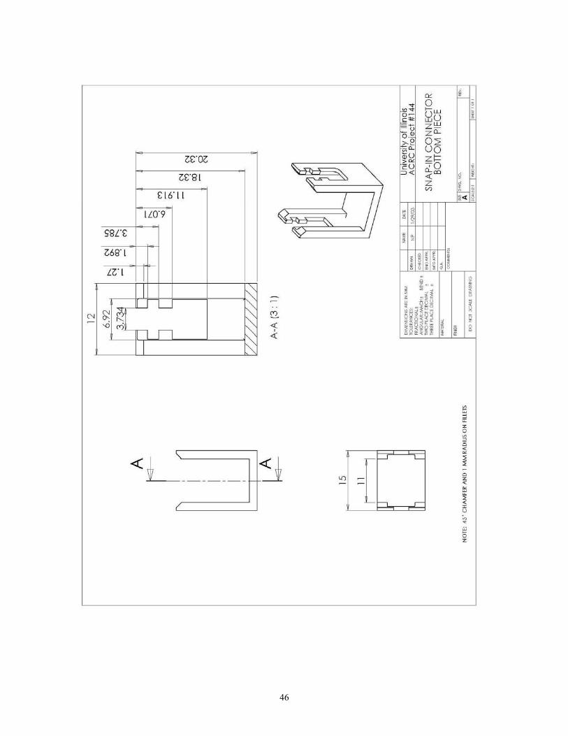
46
'" i
" 0 , ." ~ w I o ~ I,lu c~
~u ze!! 0." z"-
~~ 0::; UO
0nll >~ ~5
'" ~~ • "- ~ j I 0S·81 « z ; -w ;. ! S 16·1 1
/; IN9 • , -
<;8[£ , . , . 068·1 , ilL! ! gl
~ ! 1 1°' '''
~ - • :jl , - hi 5g~ ;
Nl ~Ln '- lj! ,
N ~ "- ~ ~ ! - ~ oj SL '" 2 .. 2 IIi i I 8 ~ « I" 1
I '" 8 2 z 0
" 0
~
-<L _______ ~ =[ ~ ~ ~ -
'" 0
- • I • u 0 · 5 z
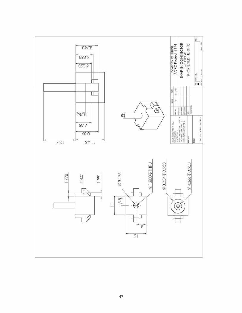
47
£9[8
8<;'8"9
£U·9
1
Il---
I<;8L
I'C9
68·8
al £V II
~ ~ 0 ro
~ .,. ": - ~ -r ~
I
"I I;)
o
'" '" I ~
'" R> ~
~ M B
B
9
ZI
'"' '" D-0 f;>
~ <Xi B
• , -, . , .
•
'"' '" D-0 f;>
'" '" '"' ~ B

48
•
OL6"CI
Z6S" I
rS:: L- - ~ --
Sl " ~ " " N '" :<!. 0- ~
.0 M ~ "" nIL 4:
I ~
\'----------,
« L __________ ~ (

49
•
8
- '" f;> iil => ~ '" '" ~ ~ I <Xi B-- ~
M ~ B-B-
/ B- \
-¥ ~$ - 1-1 EEl -'" '"
q
II

50
~ i 0 ~ , • &i . " I o ~ z
EI ~~ z OD
0.· Uz
~~ W<n
90'01 D~ 00
>~ wI
1 - ~~ 30 • w I !!!
j
~ ,"; - ~ ~ ~
~ ~ \~\ ~ ~ .. d
q f:.
- ~ 4' »- 7 ' . '"
' . ~ , I nl ! 0 i i ~
t:: ~ ! 1 1 °' '''
• :jl ,
-~ hi ,gO ; ! ' , I jL !
2 .. 2 IIi I I 8 I"
~ '" -
« ~ fc ~ f--- '" ------- '" <"i -
-9
ZI

51
u-11 " <n ej
[0
--
, . , . HILI
•
I··. !

52
£ II
, . , .
I
•

53
•
10"
' . li t
, . 0 ' I nl ! 0 i i ~
~ ! 1°'''' 1 • !i . . , . , gi ; 'f! ! .. !L
, 2 .. 2~ l' I
! l"l ,; 1 I 8
=>
'" 0
I 11 ~
I'S I
'" 00 "' 17 ;ll
i['j;""
~ ~
17 ::l '" '"
B-OO B- OO
B->--
I I
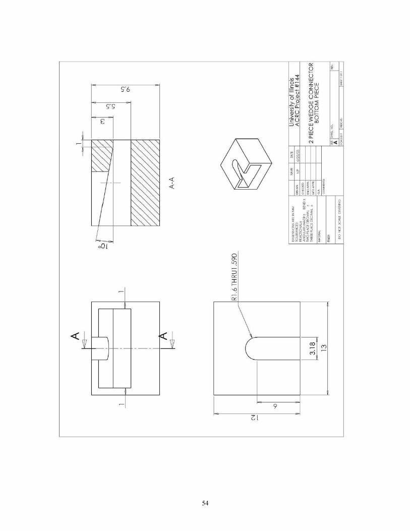
54
E
L 001
~
~ L-,
- f--~
-
~
R ~
=> De r ~
'" '"
1< + ---
01
9
, . , .
•
]~

55
• i
" Q , ." z I o ~ z ~~ 0
Uw ~.~ ~~
~5 .' U' "0 ,. z "
~~ e • • j I p: w 0
; c 0 w ;. ! • l ,
0 c
I ' . , . 0 ) nl ' I ! 0 i i ~
~ ! 1 ! ..• il , . .
; - . , gi
ld ~ - "1 , !!'" !! i ! 2 .. 2~
1i I 8 l"l 1
" 0
'" 11 " :c
"' '" -'" ~
;Jl ~ ~ R-:c -~ <Xl M " ~ £'81 "1 - S P - R-
7 B- <Xl <Xl £'v - \ s
s
~ ~ N !& 0 b - -<ri '--- I
~ 9
9
91
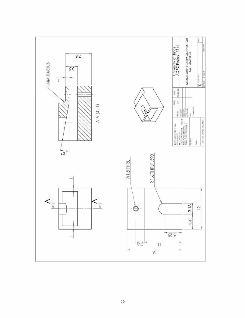
56
-< ~ I _f- -r--_- ~ ,J
9[
, . , .
•

57
" i
" 9 ,
-,
6J -
." z· 0 - z " < ~ 0 2
DD . ' u" 0 "
~~ .0 ,~
55 • ~~ j I
" ! • i , ,. • , , . , . , I ! 0 nl i i ~
'" 1 ,I '" 0 -
~ ! 1 ! ..• · . !i ,
· , gi ; 'f! , ! 1-!! ! 2 .. 2~ i l"l 1i 1 I 8
EE
r-rr 31 , -
T: '" '" CO
" N
----" ~

58
A
I I
t"\
~. B-B
45 15 11.3
=-+ ill---ill-- [!j-.I==i-,. tp B I '" ~ ~B
1.76 1.94
3.8
"' vi 5.5
I I
A-A
0 8.334 '< I .250
0 4.366
01.8 '< 3.6
@~~ 1- ~ 3Jlt
pW .. I:lK;N\ AO ' t< NM lOU' ANCa 10 ,o,cr1O_,
<:?' <?<?
•• "' .....:; ....... : _0<. et~D •
......:;. PlACI' eta""" : tHOU PlACI' ()(C_, •
_1_,
-DO tIOl "''''-, D<~WNG
~,
OA
,<>,
•• nlverSlty 0 1 ill inOIS ACRe Proiect #144
PARALLEl WEDGE CONNECTO R HOUSING BLOCK
oil 10 .... NO. ~.
A ,"""'", I....., ..

59
'" i , w
~
I 6: ~ c d « 0,_
I;;
1~ w ~
.~~ w • co I ~ Q j ~ ~
! ! « ~
I~ "" • ! " oj , , HILI
I ~ ~ .. ... '" ~ .. ~ .."
~ gU g ~ ~ !!ill! " I ~ jl!m I
w
~I ~
0 I
I 0
~ w ~
iG
II cO
~
« OS" I B
~
n ~
z CO
[0 " ,. "
-
? ~
I\t iG ill 0
- r '\ :is N
"" I
ill 0
~
EEl

60
60
ell27 ls IS el +0.02 o. 0
\j'
~ - ~ 0000 ~N 0
~ r-
.I Is C(lO: I)
\ 5x 5-40 Tapped Hole w 3.300 10 ~ 10 mm spacina 6.35
0
0 1/ 4-20 UNC To ed Hole w 6.350
~ ~
~ G
0 ~ ~
22.225 pW .. I:lK;N\ AO ' t< NM •• •• nTverSI 0 InOIS lOU' ANCa "' ..... , .. ~ ACRe PlO'ect # 144 10 ,o,cr1O_, .....:; ....... : _0<. et~D • ......:;. PlACI' eta""" : FATIGUE GRIP (HORIZONTAL) tHOU PlACI' ()(C_, •
~.-_1_, o. BOTTOM PIECE 30455 - ,
Note: 45 " chamfer on a ll tapped holes .11 0 .... NO. ~.
A DO tIOl "''''-, D<~WNG '""",'.1
_.
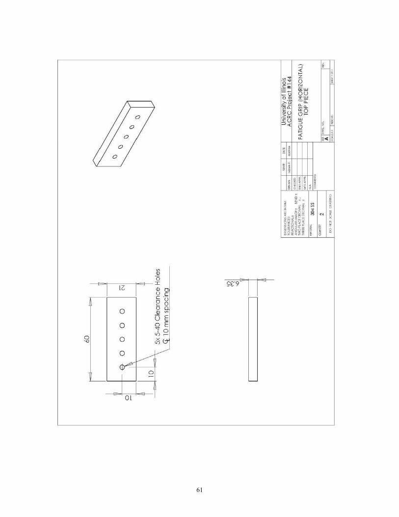
61
~ ~ ~ , ~:::
z D_ O I ~ ! '" ~W '15~ ou
X>!!
f\ ~:E -~ -~ "'~
0 ~ix ~O I) ~ w •
0 p~ ~ j I
I)
0 ~ ; -<: o i ~ ~"" ri
0
0 ~ ; , . , I , I ! 0 nl i i ~
o . ! 1 1°' ''' :jl " • •
, . , gi ~ ; 'f! ~
! 1-!! ,
2 .. 2~ i I !
l"l 1i 1 8
~
ID
"I <5
IG 1
~ I S'S"9S
U a
e g c .-o u
0 o ~ ID ~ (j E
0 o E 'fo
8 0 <0-
0<:> 0
~ L.----V
0
L-
01

62
+0.02 60 O.
18 61
If
"'''' "" R N
0 6
6 20 20 \ 4x 5-40 Tapped Holes JJo~ 0
0 (J a
2x 1/4-20 UNC TAPPED HOLE ;r 6.350
j t a (J
EB EB I ~
+ N
pW .. I:lK;N\ AO ' t< NM •• •• University.ol ll1inois lQU' ANCt:\
_. --I. -'CIIO_, ......:; ....... : _0<. et~p • """:>P\.ACI'CKl ........ : FATIGUE GRIP ~VERTlCAlJ THOU P\.ACI' ()(C_, •
~.-o. BOnOM IECE _1_, 304 SS
~~ 2 Note: 45 ~ chamfer on a ll tapped holes .11 0 .... NO. ~.
A DO tIOl "' .... , D<~WNG ,"""',., ....., ..

63
Ol
• • , , ,

64
Appendix B – Wireframe Drawings
The following wireframe drawings are representative of the four layers comprising of the heat exchanger.
Starting from the upper left layer moving in the clockwise direction are the channels layer, manifold layer, inlet and
outlet layer, and the cap layer. The two layers on top are made from Kapton® KJ and the bottom two layers are
made from Kapton® EKJ.
Original 60 mm by 60 mm heat exchanger

65
Embedded connector heat exchanger
o
o

66
Extended wedge heat exchanger

67
Extended wedge heat exchanger with screw 3 mm radius
o o
Q Q
o

68
Full size thermally bonded connection
o
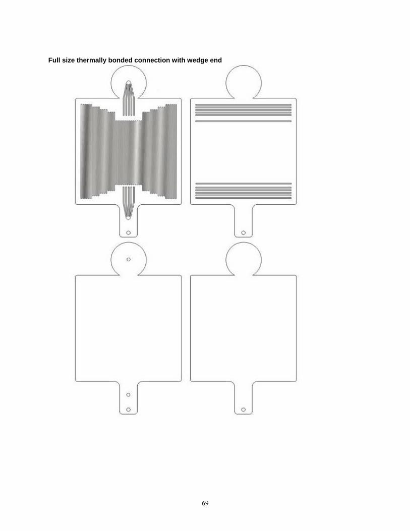
69
Full size thermally bonded connection with wedge end
0
0
--"- --"-

70
Fatigue testing heat exchanger (horizontal channel orientation)
o 0 0 0 0 o 000 0
o 0 0 0 0 o 0 000
o 0 0 0 0 o 0 000
o 0 o
o 0 0 0 0 o 0 000

71
Fatigue testing heat exchanger (vertical channel orientation)
o 0 o 0 o 0 o 0
o 0 o 0 o 0 o 0
o 0 o 0 o 0 o 0
o 0 o 0 00 o 0