Embed Size (px)
Citation preview

APPENDIX D SUMMARY SHEETS OF MEMBER SOCKET CONNECTIONS


NCHRP 12-88 Connection Evaluations Appendix D D-1
APPENDIX D SUMMARY SHEETS OF MEMBER SOCKET CONNECTIONS

NCHRP 12-88 Connection Evaluations Appendix D D-2
Location: Column to foundation Type: Member Socket: CIP spread footing
cast around precast column
Title: Connection MS-1 ED
Embedded Precast Column
TRL: Maximum TRL: 6
Source: University of Washington TRL Gaps: none

NCHRP 12-88 Connection Evaluations Appendix D D-3
BACKGROUND
Title: Connection MS-1 (Embedded Precast Column) History / Description: Precast column is set in place, and then a footing is cast around it. The
embedded portion of the column has a roughened surface.
Seismic performance tested at University of Washington.
In 2010, WSDOT constructed a bridge that was similar but also contained threaded-in horizontal bars across the PC-CIP interface.
References: Haraldsson et al. (2010 Draft)
Contact Information: Prof. John Stanton (University of Washington) – [email protected]
EVALUATION
Constructability: Risk Value: +1
Column fabrication, handling, and transportation are simplified by the use of straight headed bars in place of conventional hooked bars.
Column needs to be leveled and braced on site.
Footing easy to cast.
Stirrups in footing, required for hooked bar details, shown to be unnecessary. Seismic Performance: Value: 0
Emulative performance – similar to ductile CIP connection.
Footing remains undamaged and all inelastic deformation occurs in column plastic hinge.
Stresses in joint region more direct than with conventional bent-out hooked bars.
Inspectability: Value: 0
Footing is easily inspected. Column inspection depends on casting method.
Durability: Value: +1
Expected to be similar to CIP concrete. Might be better, since a CIP system typically contains a horizontal cold joint at the top of the footing with steel crossing it.
Time Saving Potential: Value: +2
No column connection steel has to be installed in the footing
TRL Comments: Additional Comments:

NCHRP 12-88 Connection Evaluations Appendix D D-4
Location: Column to foundation Type: Member Socket: Precast column
grouted into hole in CIP spread
Title: Connection MS-2 footing. ED
Grouted Precast Column
TRL: Maximum TRL: 6
Source: University of Bergamo, Italy TRL Gaps: None

NCHRP 12-88 Connection Evaluations Appendix D D-5
BACKGROUND
Title: Connection MS-2 (Grouted Precast Column) History / Description: A footing is cast with a hole in it. The precast column is grouted into the pre-
formed hole in the footing.
This type of connection has been used in Italy to connect building columns to mat foundations or pocket footings.
Seismic performance was tested at the University of Brescia, Italy. References: Riva (2006) Contact Information: Paolo Riva – [email protected]
EVALUATION
Constructability: Risk Value: +2
Column fabrication, handling, and transportation are simplified by the use of straight headed bars in place of conventional hooked bars.
Column needs to be leveled and braced on site.
Adequate tolerances to place the column within footing. Seismic Performance: Value: 0
Emulative performance – similar to ductile CIP connection.
Footing remains undamaged and all inelastic deformation occurs in column plastic hinge.
Inspectability: Value: 0
Inspectability is the same as for CIP constructed connection
Durability: Value: +1
Expected to be similar to CIP concrete. Might be better, since a CIP system typically contains a horizontal cold joint at the top of the footing with steel crossing it.
Time Saving Potential: Value: +2
No iron work needed for footing/column installation
TRL Comments: Additional Comments: The connection has been applied and researched related to buildings in Italy.

NCHRP 12-88 Connection Evaluations Appendix D D-6
Location: Column to foundation Type: Member Socket: Concrete-filled tube
with annular ring connection to
Title: Connection MS-3 spread footing ED
Embedded Concrete Filled Steel Tube
TRL: Maximum TRL: 6
Source: University of Washington TRL Gaps: none

NCHRP 12-88 Connection Evaluations Appendix D D-7
BACKGROUND
Title: Connection MS-3 (Embedded Concrete Filled Steel Tube) History / Description: The connection can be built in two ways. Option 1: The footing is cast with a
hole formed using a corrugated steel duct. The CFT is inserted in the hole and the interface between the footing and column is grouted. Option 2: The CFT is inserted in the rebar cage and the footing is cast around the column.
The annular ring is welded to the base of the CFT.
Seismic performance has been tested at the University of Washington.
References: Roeder and Lehman (Accepted for publication), Roeder et al. (2009), Kingsley
(2005) Contact Information: Prof. Charles Roeder – [email protected]
EVALUATION
Constructability: Risk Value: -1
Does footing reinf cage have to be built after column is placed b/c of annular ring?
Seismic Performance: Value: 0
Experimental testing of column to footing connections at the University of Washington has shown ductile performance with no footing damage.
Inspectability: Value: 0
Inspectability same as for CIP concrete filled steel tubes
Durability: Value: 0
Durability same as for CIP concrete filled steel tubes
Time Saving Potential: Value: +1
No column connection steel has to be installed in the footing
TRL Comments: Additional Comments:

NCHRP 12-88 Connection Evaluations Appendix D D-8
Location: Column to foundation Type: Member Socket/Grouted Bars: FRP Tubes as stay-in-place formwork filled with concrete conventionally reinforced or post-tensioned
ED
Title: Connection MS-4
Embedded Concrete Filled FRP Tube
TRL: Maximum TRL: 5
Source: Florida International University TRL Gaps: none

NCHRP 12-88 Connection Evaluations Appendix D D-9
BACKGROUND
Title: Connection MS-4 (Embedded Concrete Filled FRP Tube) History / Description: A column is built of with a stay-in-place fiber reinforced polymer formwork that
provides hoop and longitudinal stiffness with a +/- 50 degree fiber layup. The Concrete Filled Fiber Reinforced Polymer Tube (CFFT) is embedded in the footing over 12 inches (305 mm) or the diameter of the tube and is fully reinforced along its entire height with conventional steel reinforcement. The CFFT is either cast-in-place with the footing or precast and connected to the footing with a combination of member socket and grouted starter bars. One specimen used PT bars instead of mild steel bars.
Seismic performance was tested at Florida International University. The CFFT provided an additional 30% strength over the conventional column without stay-in-place formwork. The CFFT systems reached a ductile response with a ductility of 10%.
Monotonic testing of FRP anchorage in concrete with no reinforcing bars across the connection interface has been performed at Queen’s University.
References: Zhu et al. (2006), Nelson et al. (2008),
Contact Information: Amir Mirmiran, Florida International University
EVALUATION
Constructability: Risk Value: 0
The grouted bar/member socket combination adds two grouting steps to the construction, but iron tying for the construction is minimized
The grouted bars extending out of the footing will have to be carefully placed at tight tolerances
Inspection of the grouted areas is difficult Seismic Performance: Value: +2
The testing at Florida International University showed a promising ductile behavior at no spalling of concrete.
Inspectability: Value: +1
It can be assumed that as long as the CFFT is intact, no bar has failed within the tube.
Durability: Value: +1
The concrete and reinforcement steel is protected by the CFFT. However, the CFFT has to be protected from UV degradation and damage.
Time Saving Potential: Value: +2
Time savings are similar to other socket member connections but the need for grouting the bars will add one step. However, the simplified column reinforcement (no need for spiral reinforcement) can make it up for it.
TRL Comments: Testing has only been performed on relatively lightly reinforced scaled columns. Additional Comments: ACI committee 440

NCHRP 12-88 Connection Evaluations Appendix D D-10
Location: Pile to pile cap Type: Member Socket: Precast pile cap to
concrete pile
Title: Connection MS-5 ED
FHWA Connection Manual – 3.1.1.1.A
TRL: Maximum TRL: 3
Source: Minnesota DOT TRL Gaps: None
NCHRP 12-88 Connection Evaluations Appendix D D-11
BACKGROUND
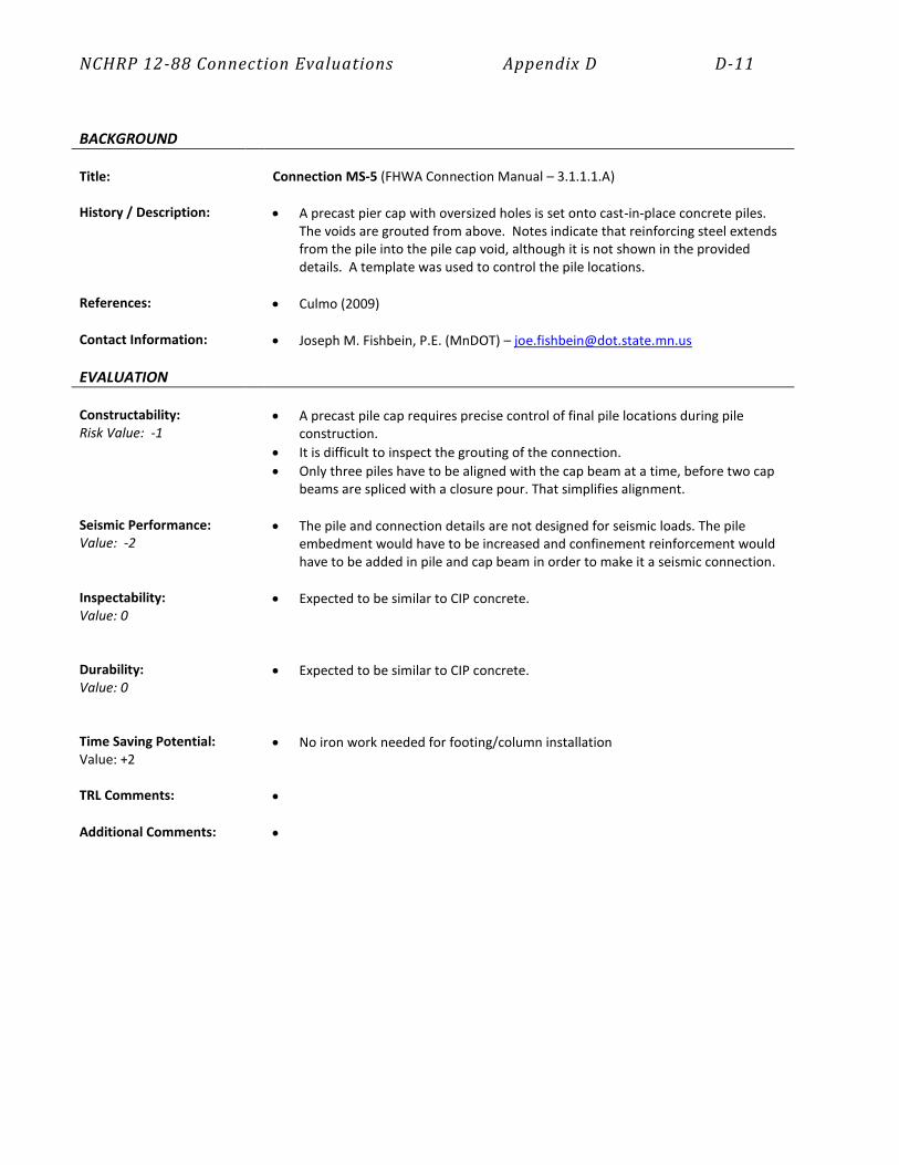
Title: Connection MS-5 (FHWA Connection Manual – 3.1.1.1.A) History / Description: A precast pier cap with oversized holes is set onto cast-in-place concrete piles.
The voids are grouted from above. Notes indicate that reinforcing steel extends from the pile into the pile cap void, although it is not shown in the provided details. A template was used to control the pile locations.
References: Culmo (2009) Contact Information: Joseph M. Fishbein, P.E. (MnDOT) – [email protected]
EVALUATION
Constructability: Risk Value: -1
A precast pile cap requires precise control of final pile locations during pile construction.
It is difficult to inspect the grouting of the connection.
Only three piles have to be aligned with the cap beam at a time, before two cap beams are spliced with a closure pour. That simplifies alignment.
Seismic Performance: Value: -2
The pile and connection details are not designed for seismic loads. The pile embedment would have to be increased and confinement reinforcement would have to be added in pile and cap beam in order to make it a seismic connection.
Inspectability: Value: 0
Expected to be similar to CIP concrete.
Durability: Value: 0
Expected to be similar to CIP concrete.
Time Saving Potential: Value: +2
No iron work needed for footing/column installation
TRL Comments: Additional Comments:

NCHRP 12-88 Connection Evaluations Appendix D D-12
Location: Pile to pile cap Type: Member Socket: Precast pile cap to
concrete pile
Title: Connection MS-6 ED
FHWA Connection Manual – 3.1.1.4.C
TRL: Maximum TRL: 3
Source: Louisiana DOT TRL Gaps: None

NCHRP 12-88 Connection Evaluations Appendix D D-13
BACKGROUND
Title: Connection MS-6 (FHWA Connection Manual – 3.1.1.4.C) History / Description: A precast pile cap with oversized holes is set onto precast concrete piles. A single
reinforcing bar, called a drift pin in the detail, extends between the pile and void in the pile cap. The void is grouted to connect the two elements. The reference states that the connection is designed as a pin to transmit “lateral forces and axial compression”.
References: Culmo (2009) Contact Information: Paul Fossier (LDOT) – [email protected]
EVALUATION
Constructability: Risk Value: -1
A precast pile cap requires precise control of final pile locations during pile construction.
It is difficult to inspect the grouting of the connection.
Only three piles have to be aligned with the cap beam at a time, before two cap beams are spliced with a closure pour. That simplifies alignment.
Seismic Performance: Value: -2
The pile and connection details are not designed for seismic loads. The pile embedment would have to be increased and confinement reinforcement would have to be added in pile and cap beam in order to make it a seismic connection.
Inspectability: Value: 0
Expected to be similar to CIP concrete.
Durability: Value: 0
Expected to be similar to CIP concrete.
Time Saving Potential: Value: +2
No iron work needed for footing/column installation
TRL Comments: Additional Comments: