Embed Size (px)
Citation preview
Connection Design Assistance Manual
ArchitecturalPrecast
Concrete
GlassFiber
ReinforcedConcrete
CastStone
Architectural Precast Association | 6710 Winkler Road, Suite 8 | Fort Myers, FL 33919 Phone: 239-454-6989 | Fax: 239-454-6787 | E-mail: [email protected]
TABLE OF CONTENTS
11/13/2006i
PART 1 - ARCHITECTUAL PRECAST CONCRETE 1.1 CONCRETE STRUCTURE............................................................................................1-1
A. Type 1 - Load Bearing to Floor Slab ........................................................................1-1 B. Type 2 - Load Bearing to Floor Slab ........................................................................1-2 C. Type 3 - Load Bearing to Floor Slab ........................................................................1-3 D. Type 4 - Load Bearing to Floor Slab ........................................................................1-4 E. Type 5 - Load Bearing to Floor Slab ........................................................................1-5 F. Lateral Tieback to Top of Slab .................................................................................1-6 G. Load to Foundation or Curb .....................................................................................1-7 H. Load Bearing to Cast-in-Place Curb.........................................................................1-8 I. Load and Tieback to Shear Wall ..............................................................................1-9 J. Lateral Tieback to Shear Wall ................................................................................1-10
1.2 STEEL STRUCTURE...................................................................................................1-11 A. Load to Column......................................................................................................1-11 B. Load to Perimeter Beam ........................................................................................1-12 C. Tieback to Top of Beam .........................................................................................1-13 D. Tie Back Top of Concrete Deck .............................................................................1-14 E. Tie Back to Underside of Beam..............................................................................1-15 F. Lateral Connection Below Beam............................................................................1-16 G. Tie back Connection to Column .............................................................................1-17
1.3 MISCELLANEOUS CONNECTIONS ...........................................................................1-18 A. Panel to Panel Stacked Load Bearing....................................................................1-18 B. Panel to Panel Load Bearing..................................................................................1-19 C. Panel to Panel – Non Load Bearing .......................................................................1-20 D. Panel to Panel – Non Load Bearing .......................................................................1-21 E. Type 1 - Column Enclosures Connection...............................................................1-22 F. Type 2 - Column Enclosures Connection...............................................................1-23 G. Load Bearing Below Structure................................................................................1-24
PART 2 - GLASS FIBER REINFORCED CONCRETE (GFRC) 2.1 CONNECTIONS.............................................................................................................2-1
A. Load to Top of Perimeter Beam ...............................................................................2-1 B. Tie Back to Underside of Steel Beam ......................................................................2-2 C. Roof Cornice ............................................................................................................2-3 D. Load Bearing to Concrete Floor Slab .......................................................................2-4 E. Lateral Tieback to Underside of Concrete Slab........................................................2-5 F. Accent Banding ........................................................................................................2-6 G. Soffit .........................................................................................................................2-7

TABLE OF CONTENTS
11/13/2006
PART 3 - CAST STONE 3.1 CONNECTIONS.............................................................................................................3-1
A. Accent Banding Without Mechanical Fasteners.......................................................3-1 B. Accent Banding With Mechanical Fasteners............................................................3-2 C. Window Sill...............................................................................................................3-3 D. Window Lintels .........................................................................................................3-4 E. Doweled Coping .......................................................................................................3-5 F. Multiple Units with Mechanical Fasteners ................................................................3-6 G. Parapet - Control Joints............................................................................................3-7 H. Soffits .......................................................................................................................3-8 I. Watertable ................................................................................................................3-9
ii

PART 1
Architectural Precast
Concrete
Architectural Precast Concrete
Each illustrative connection is shown for concept only. All connections must be engineered for project specific lateral and loading requirements.
All connections must be approved by a licenced engineerer.
1-1 11/13/2006
PART 1 - ARCHITECTUAL PRECAST CONCRETE
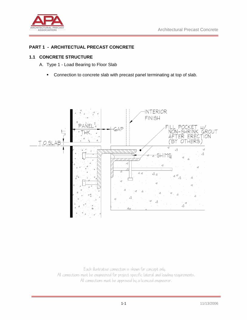
1.1 CONCRETE STRUCTURE A. Type 1 - Load Bearing to Floor Slab
Connection to concrete slab with precast panel terminating at top of slab.

Architectural Precast Concrete
Each illustrative connection is shown for concept only. All connections must be engineered for project specific lateral and loading requirements.
All connections must be approved by a licenced engineerer.
1-2 11/13/2006
B. Type 2 - Load Bearing to Floor Slab
Top of panel terminates above floor line. Load bearing to concrete floor slab with recessed pocket. Embed recessed so not to interfere with interior finishes.

Architectural Precast Concrete
Each illustrative connection is shown for concept only. All connections must be engineered for project specific lateral and loading requirements.
All connections must be approved by a licenced engineerer.
1-3 11/13/2006
C. Type 3 - Load Bearing to Floor Slab
Projecting bearing plate flush with top of slab. Ideal for minimum distance from edge of slab to interior finishes.
Architectural Precast Concrete
Each illustrative connection is shown for concept only. All connections must be engineered for project specific lateral and loading requirements.
All connections must be approved by a licenced engineerer.
1-4 11/13/2006
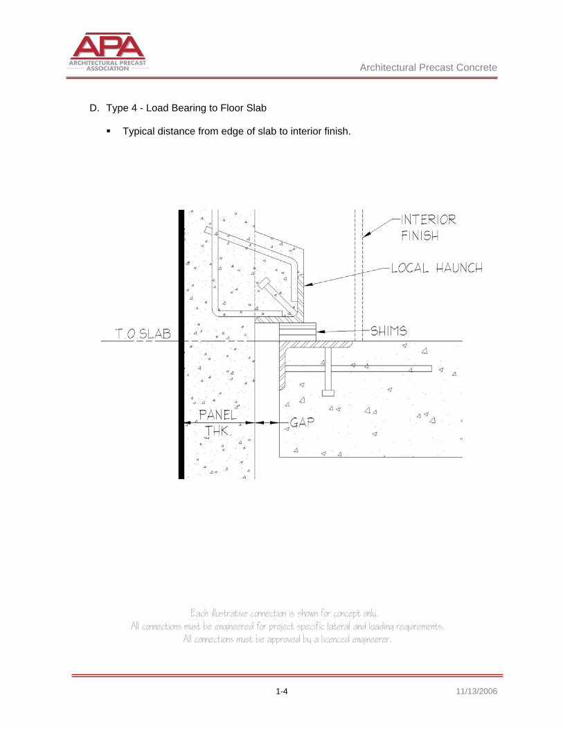
D. Type 4 - Load Bearing to Floor Slab
Typical distance from edge of slab to interior finish.
Architectural Precast Concrete
Each illustrative connection is shown for concept only. All connections must be engineered for project specific lateral and loading requirements.
All connections must be approved by a licenced engineerer.
1-5 11/13/2006
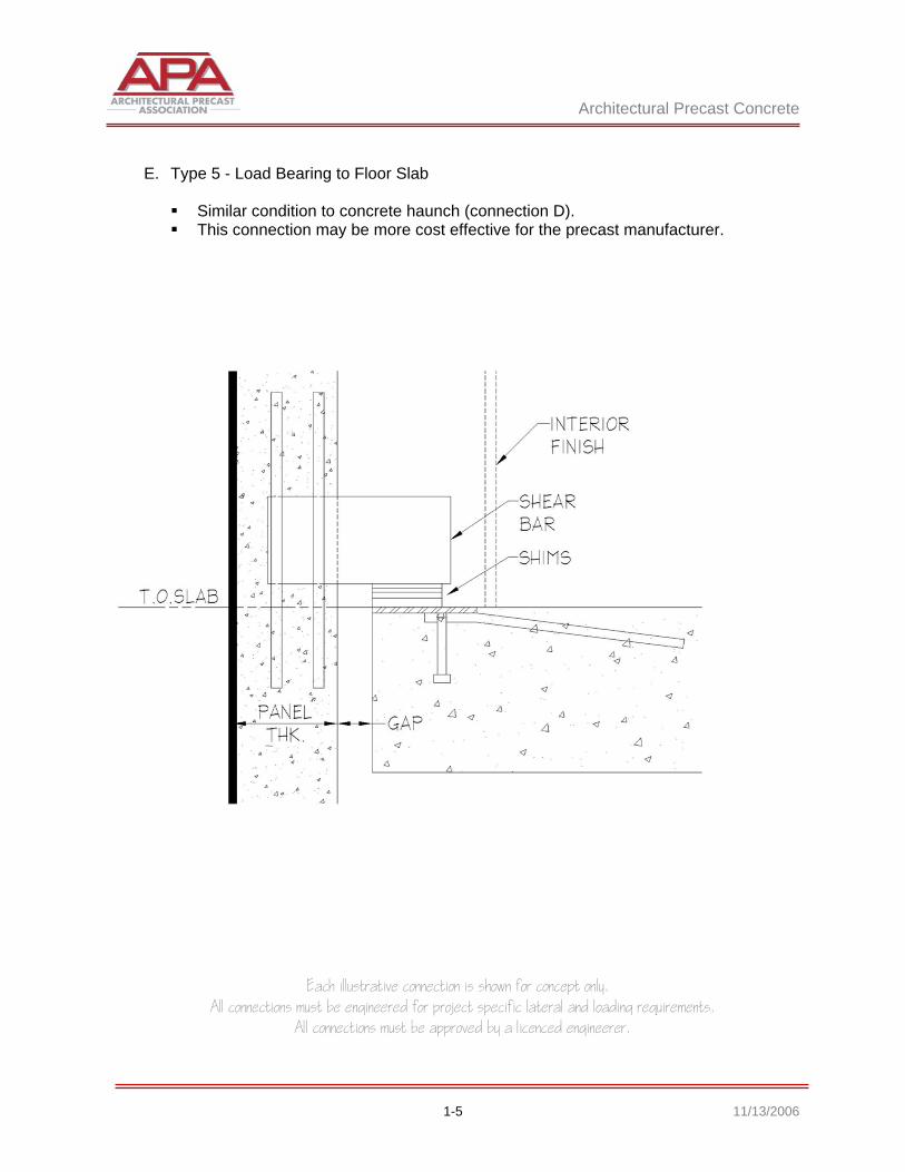
E. Type 5 - Load Bearing to Floor Slab
Similar condition to concrete haunch (connection D). This connection may be more cost effective for the precast manufacturer.
Architectural Precast Concrete
Each illustrative connection is shown for concept only. All connections must be engineered for project specific lateral and loading requirements.
All connections must be approved by a licenced engineerer.
1-6 11/13/2006
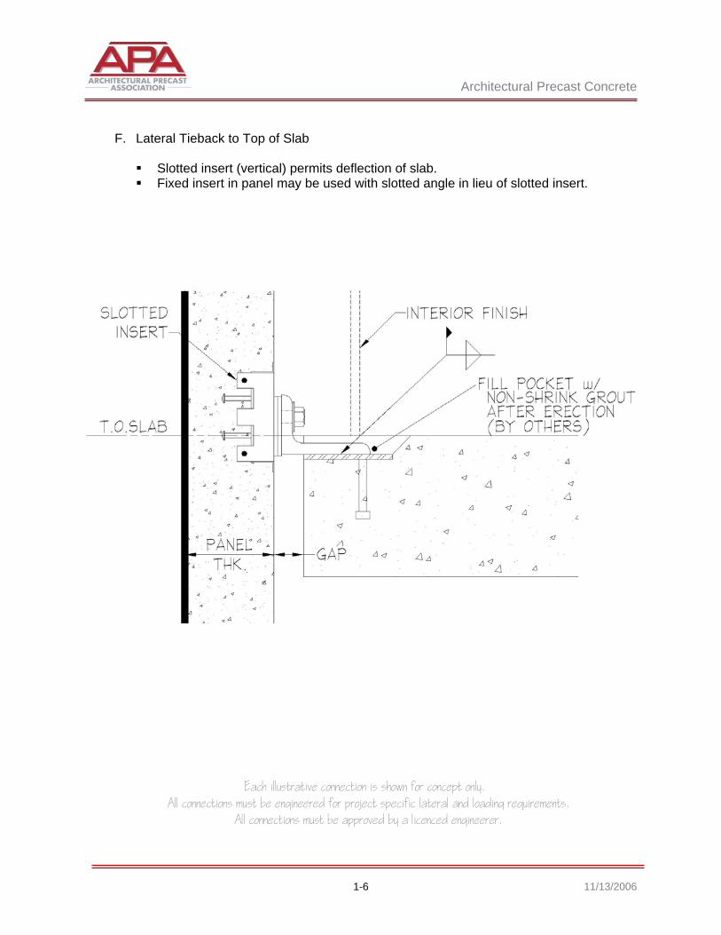
F. Lateral Tieback to Top of Slab
Slotted insert (vertical) permits deflection of slab. Fixed insert in panel may be used with slotted angle in lieu of slotted insert.
Architectural Precast Concrete
Each illustrative connection is shown for concept only. All connections must be engineered for project specific lateral and loading requirements.
All connections must be approved by a licenced engineerer.
1-7 11/13/2006
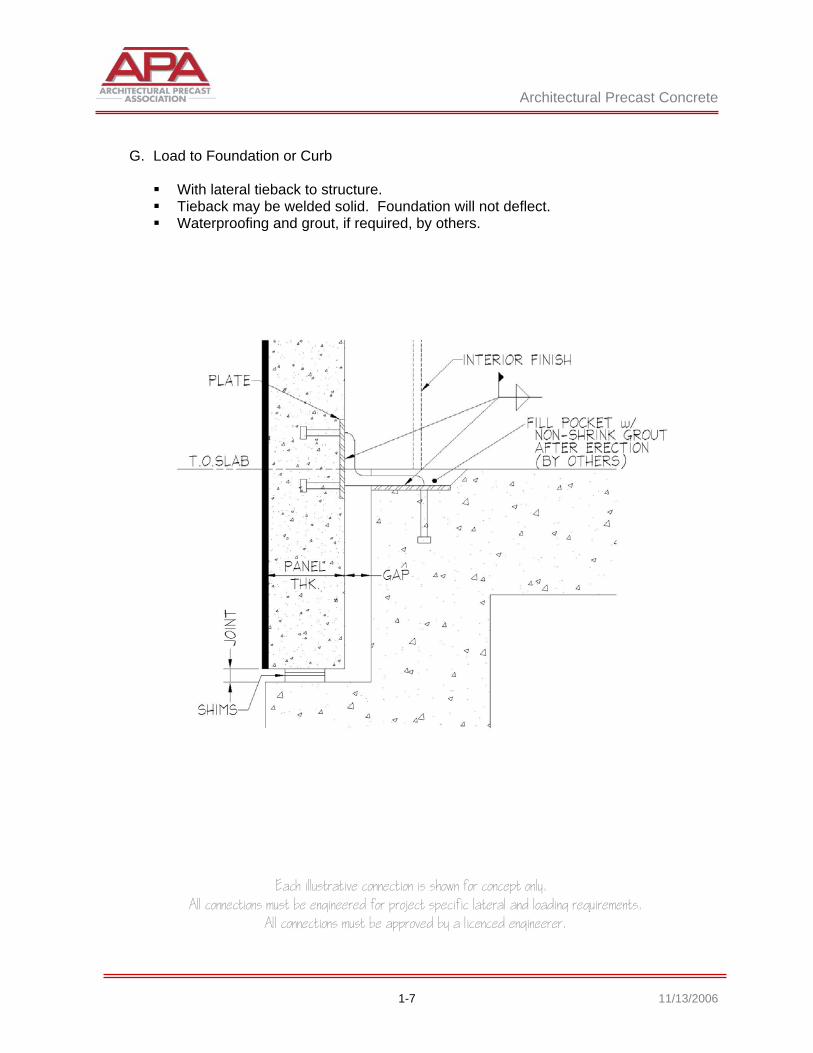
G. Load to Foundation or Curb
With lateral tieback to structure. Tieback may be welded solid. Foundation will not deflect. Waterproofing and grout, if required, by others.
Architectural Precast Concrete
Each illustrative connection is shown for concept only. All connections must be engineered for project specific lateral and loading requirements.
All connections must be approved by a licenced engineerer.
1-8 11/13/2006
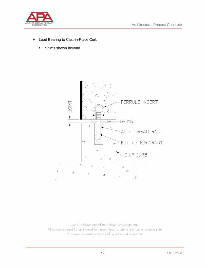
H. Load Bearing to Cast-in-Place Curb
Shims shown beyond.
Architectural Precast Concrete
Each illustrative connection is shown for concept only. All connections must be engineered for project specific lateral and loading requirements.
All connections must be approved by a licenced engineerer.
1-9 11/13/2006
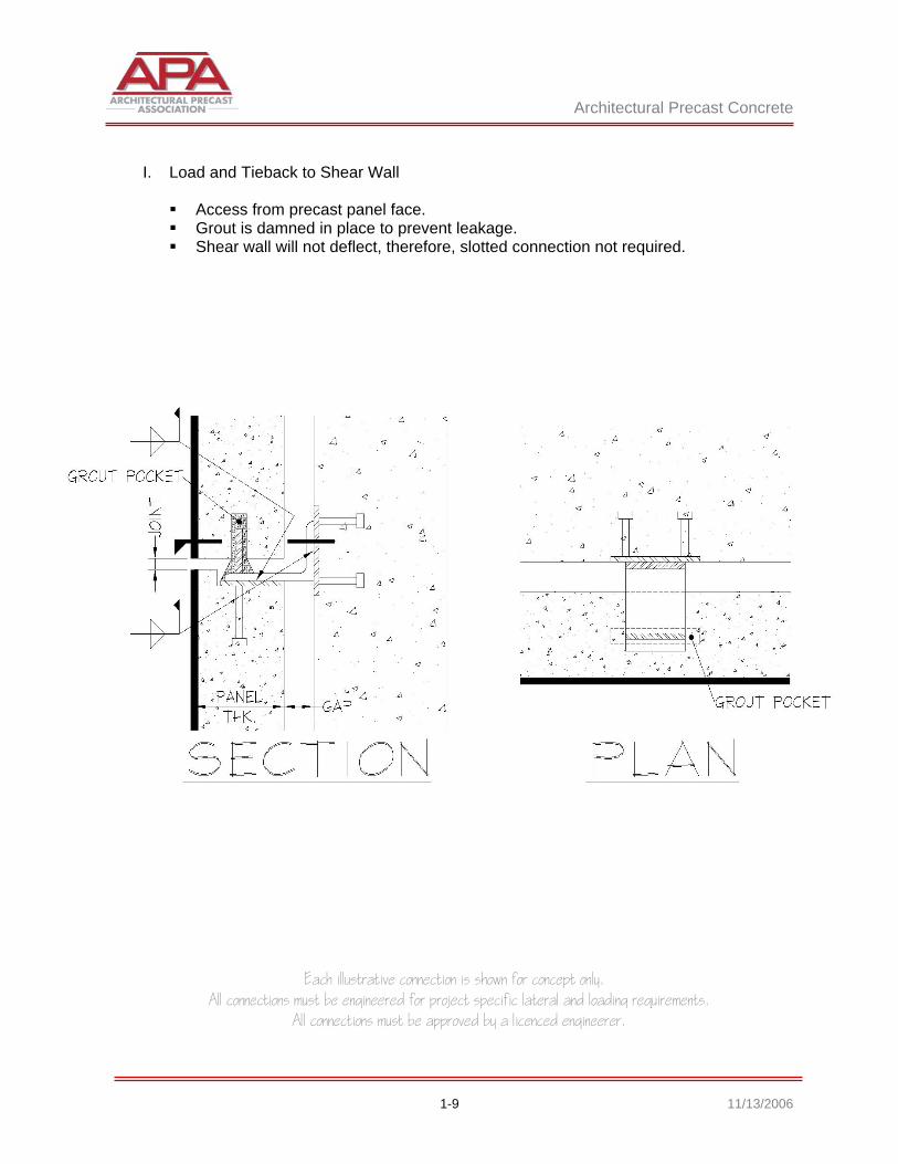
I. Load and Tieback to Shear Wall
Access from precast panel face. Grout is damned in place to prevent leakage. Shear wall will not deflect, therefore, slotted connection not required.
Architectural Precast Concrete
Each illustrative connection is shown for concept only. All connections must be engineered for project specific lateral and loading requirements.
All connections must be approved by a licenced engineerer.
1-10 11/13/2006
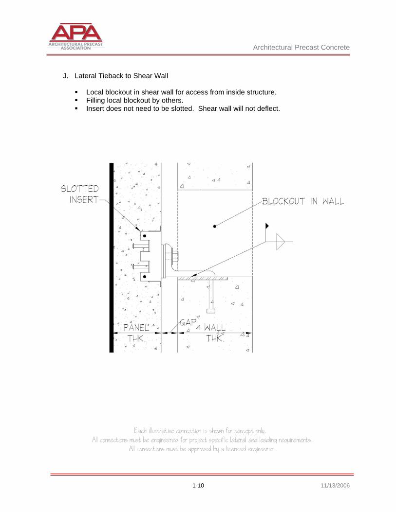
J. Lateral Tieback to Shear Wall
Local blockout in shear wall for access from inside structure. Filling local blockout by others. Insert does not need to be slotted. Shear wall will not deflect.

Architectural Precast Concrete
Each illustrative connection is shown for concept only. All connections must be engineered for project specific lateral and loading requirements.
All connections must be approved by a licenced engineerer.
1-11 11/13/2006
1.2 STEEL STRUCTURE A. Load to Column
The precast erector may weld the plates to the column or they may be welded in
the shop by the steel fabricator. Note that the connection is symmetrical about the centerline of column. Each load-
bearing angle receives a tie back connection. Angle with slots may be used in lieu of slotted inserts
Architectural Precast Concrete
Each illustrative connection is shown for concept only. All connections must be engineered for project specific lateral and loading requirements.
All connections must be approved by a licenced engineerer.
1-12 11/13/2006
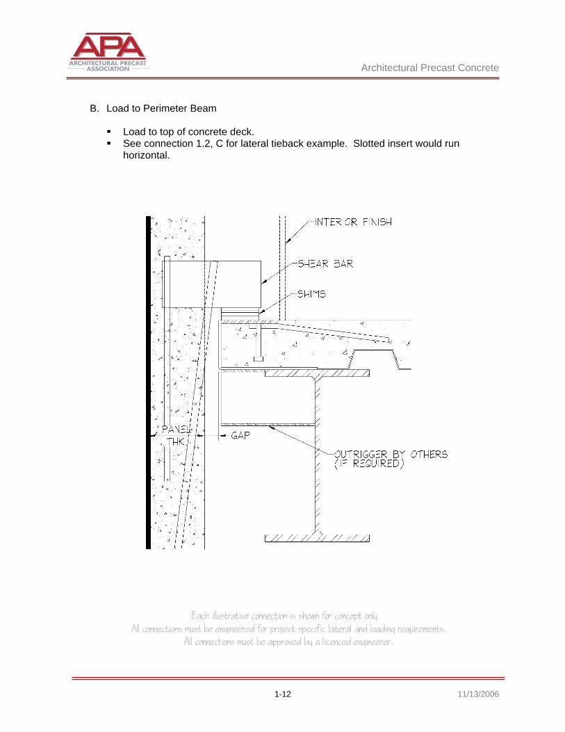
B. Load to Perimeter Beam
Load to top of concrete deck. See connection 1.2, C for lateral tieback example. Slotted insert would run
horizontal.

Architectural Precast Concrete
Each illustrative connection is shown for concept only. All connections must be engineered for project specific lateral and loading requirements.
All connections must be approved by a licenced engineerer.
1-13 11/13/2006
C. Tieback to Top of Beam
Architectural Precast Concrete
Each illustrative connection is shown for concept only. All connections must be engineered for project specific lateral and loading requirements.
All connections must be approved by a licenced engineerer.
1-14 11/13/2006
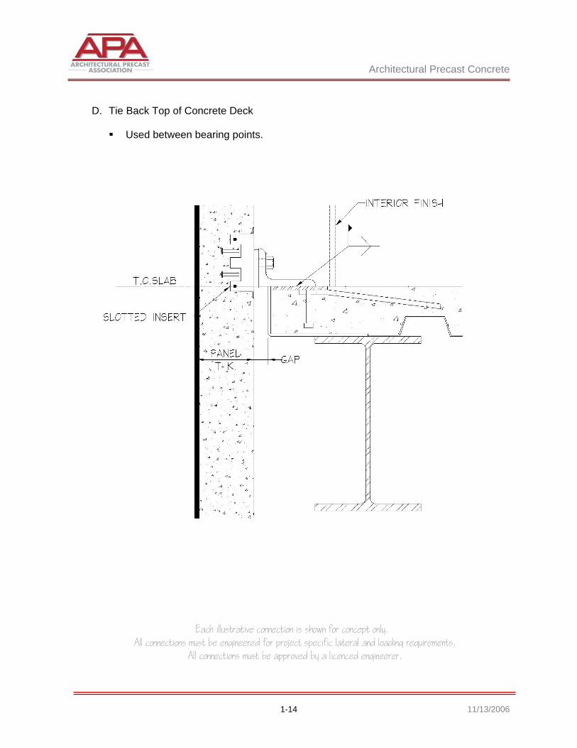
D. Tie Back Top of Concrete Deck
Used between bearing points.

Architectural Precast Concrete
Each illustrative connection is shown for concept only. All connections must be engineered for project specific lateral and loading requirements.
All connections must be approved by a licenced engineerer.
1-15 11/13/2006
E. Tie Back to Underside of Beam
Bracing of beam may be required to prevent twisting due to lateral loads.

Architectural Precast Concrete
Each illustrative connection is shown for concept only. All connections must be engineered for project specific lateral and loading requirements.
All connections must be approved by a licenced engineerer.
1-16 11/13/2006
F. Lateral Connection Below Beam
Connection falls below structure. May be used when more panel hangs below top of slab and lateral bracing is
required. Field installed.

Architectural Precast Concrete
Each illustrative connection is shown for concept only. All connections must be engineered for project specific lateral and loading requirements.
All connections must be approved by a licenced engineerer.
1-17 11/13/2006
G. Tie back Connection to Column
Angle shown. Plates or channels may be used when interior finish to column is reduced.
Architectural Precast Concrete
Each illustrative connection is shown for concept only. All connections must be engineered for project specific lateral and loading requirements.
All connections must be approved by a licenced engineerer.
1-18 11/13/2006
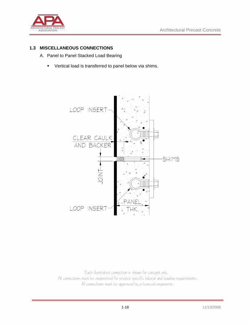
1.3 MISCELLANEOUS CONNECTIONS A. Panel to Panel Stacked Load Bearing
Vertical load is transferred to panel below via shims.
Architectural Precast Concrete
Each illustrative connection is shown for concept only. All connections must be engineered for project specific lateral and loading requirements.
All connections must be approved by a licenced engineerer.
1-19 11/13/2006
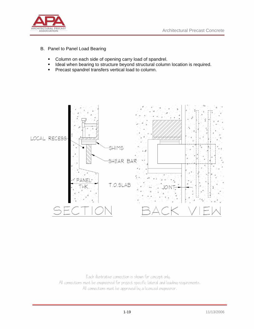
B. Panel to Panel Load Bearing
Column on each side of opening carry load of spandrel. Ideal when bearing to structure beyond structural column location is required. Precast spandrel transfers vertical load to column.
Architectural Precast Concrete
Each illustrative connection is shown for concept only. All connections must be engineered for project specific lateral and loading requirements.
All connections must be approved by a licenced engineerer.
1-20 11/13/2006
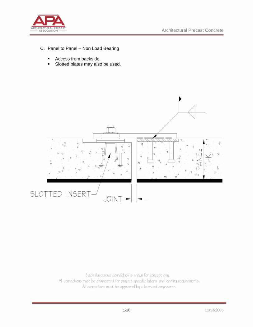
C. Panel to Panel – Non Load Bearing
Access from backside. Slotted plates may also be used.

Architectural Precast Concrete
Each illustrative connection is shown for concept only. All connections must be engineered for project specific lateral and loading requirements.
All connections must be approved by a licenced engineerer.
1-21 11/13/2006
D. Panel to Panel – Non Load Bearing
Slip connection for panel-to-panel alignment only. Ideal for above roofline when exposed to view.
Architectural Precast Concrete
Each illustrative connection is shown for concept only. All connections must be engineered for project specific lateral and loading requirements.
All connections must be approved by a licenced engineerer.
1-22 11/13/2006
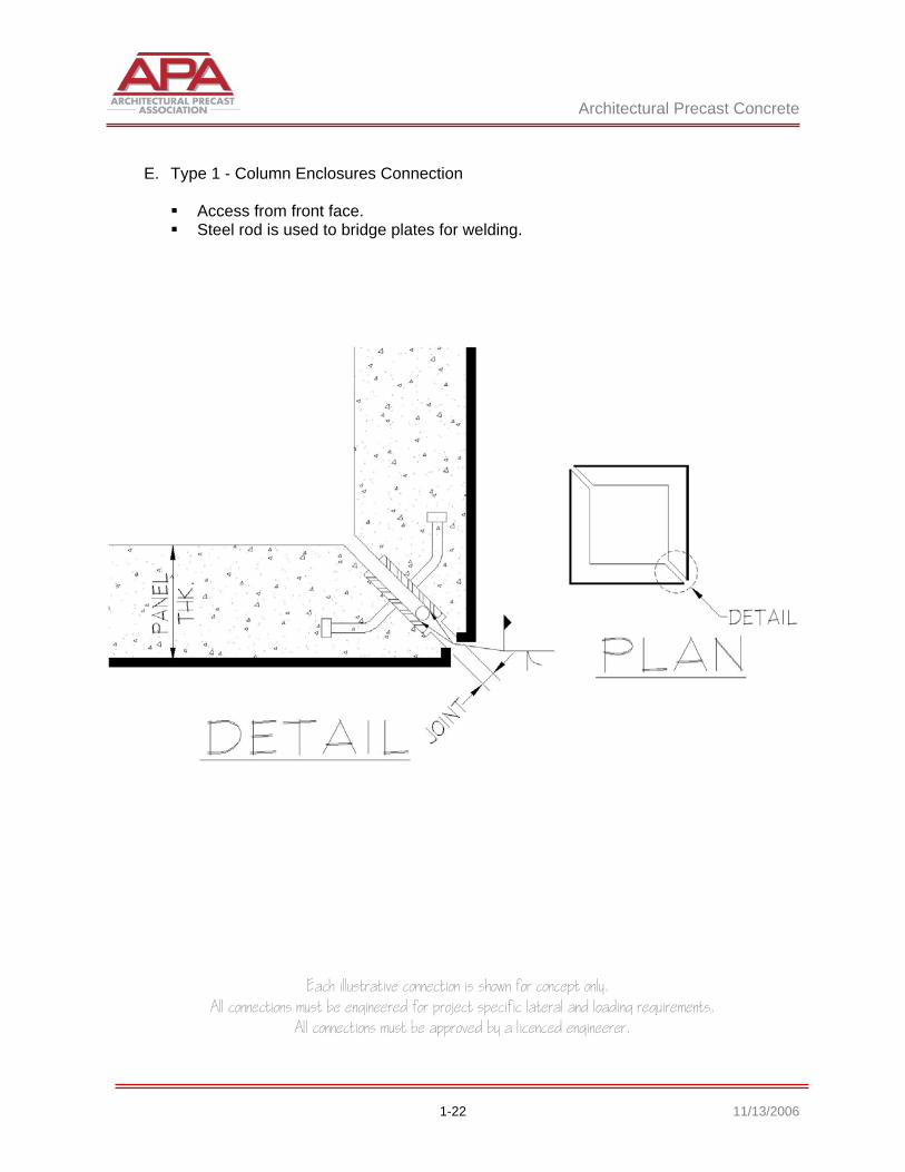
E. Type 1 - Column Enclosures Connection
Access from front face. Steel rod is used to bridge plates for welding.
Architectural Precast Concrete
Each illustrative connection is shown for concept only. All connections must be engineered for project specific lateral and loading requirements.
All connections must be approved by a licenced engineerer.
1-23 11/13/2006
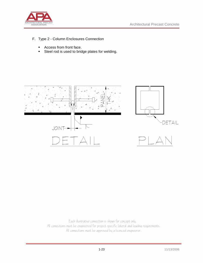
F. Type 2 - Column Enclosures Connection
Access from front face. Steel rod is used to bridge plates for welding.

Architectural Precast Concrete
Each illustrative connection is shown for concept only. All connections must be engineered for project specific lateral and loading requirements.
All connections must be approved by a licenced engineerer.
1-24 11/13/2006
G. Load Bearing Below Structure
Used primarily with excessive floor-to-floor heights. Concrete structure shown. Steel structure similar.
PART 2
Glass Fiber Reinforced Concrete

Glass Fiber Reinforced Concrete
Each illustrative connection is shown for concept only. All connections must be engineered for project specific lateral and loading requirements.
All connections must be approved by a licenced engineerer.
2-1 11/13/2006
PART 2 - GLASS FIBER REINFORCED CONCRETE (GFRC)
2.1 CONNECTIONS A. Load to Top of Perimeter Beam
Large window unit panelization. Bearing angle is pre-attached to subframe. Steel frame picks up window dead loads.
Glass Fiber Reinforced Concrete
Each illustrative connection is shown for concept only. All connections must be engineered for project specific lateral and loading requirements.
All connections must be approved by a licenced engineerer.
2-2 11/13/2006
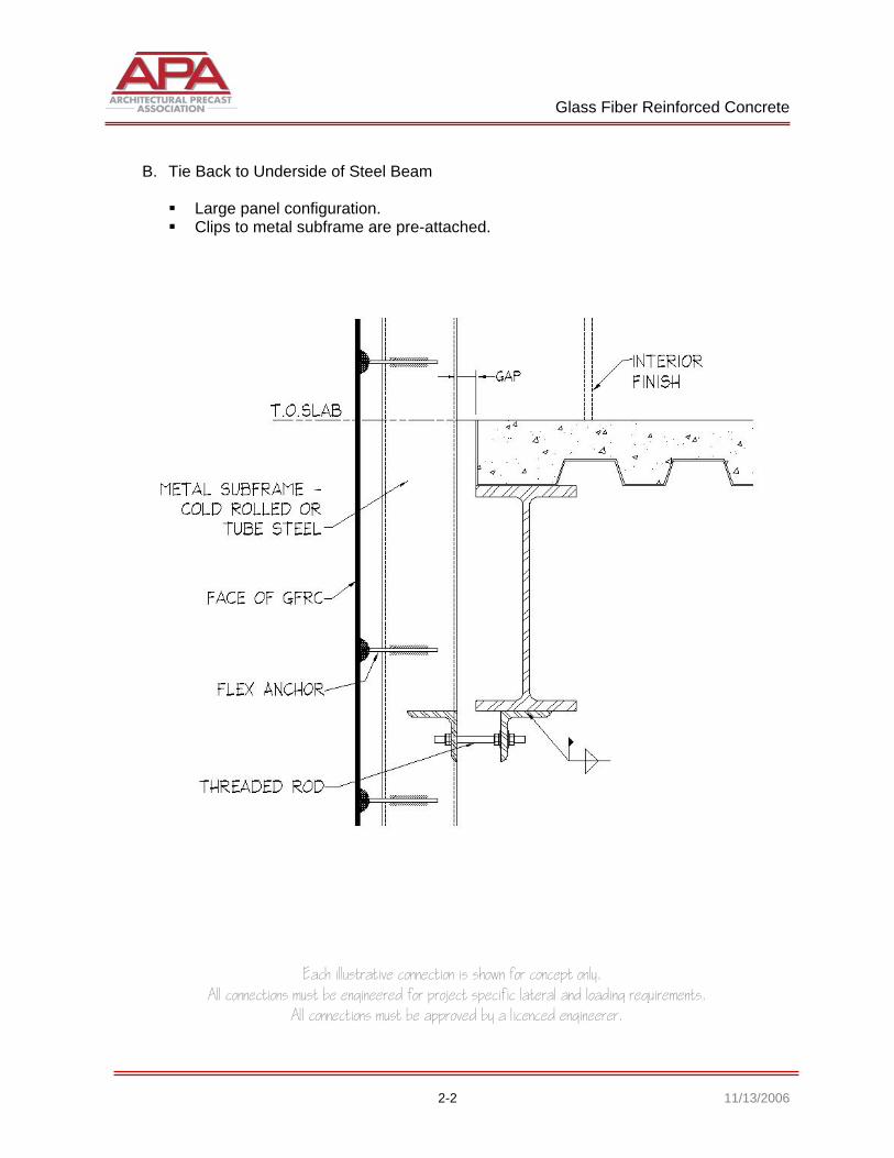
B. Tie Back to Underside of Steel Beam
Large panel configuration. Clips to metal subframe are pre-attached.
Glass Fiber Reinforced Concrete
Each illustrative connection is shown for concept only. All connections must be engineered for project specific lateral and loading requirements.
All connections must be approved by a licenced engineerer.
2-3 11/13/2006
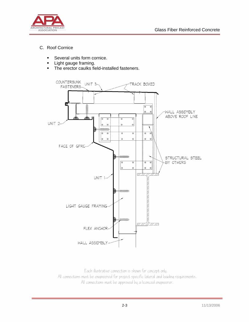
C. Roof Cornice
Several units form cornice. Light gauge framing. The erector caulks field-installed fasteners.
Glass Fiber Reinforced Concrete
Each illustrative connection is shown for concept only. All connections must be engineered for project specific lateral and loading requirements.
All connections must be approved by a licenced engineerer.
2-4 11/13/2006
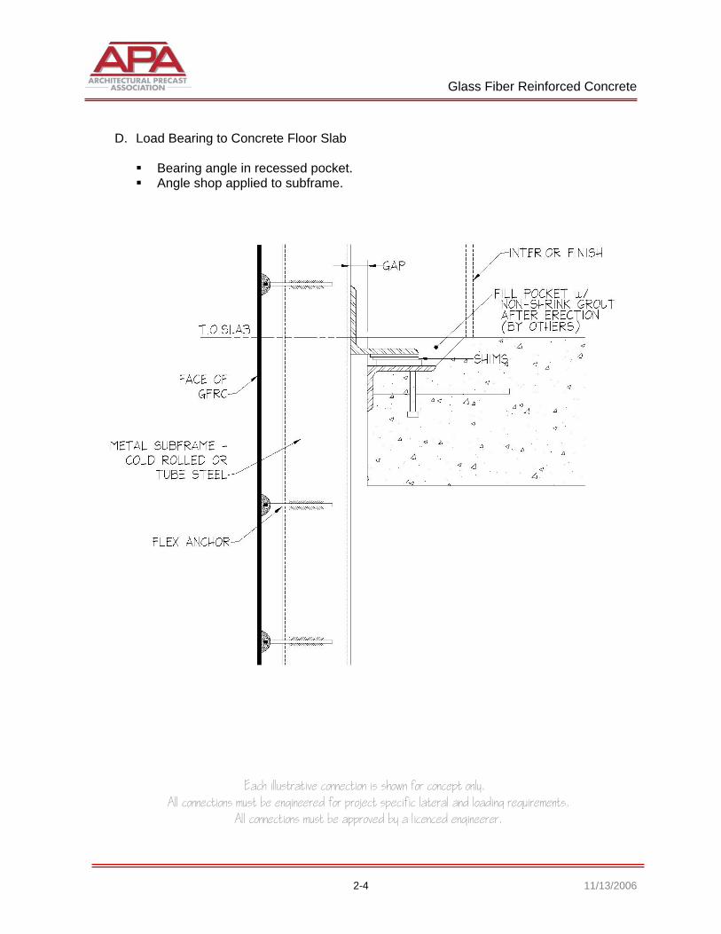
D. Load Bearing to Concrete Floor Slab
Bearing angle in recessed pocket. Angle shop applied to subframe.
Glass Fiber Reinforced Concrete
Each illustrative connection is shown for concept only. All connections must be engineered for project specific lateral and loading requirements.
All connections must be approved by a licenced engineerer.
2-5 11/13/2006
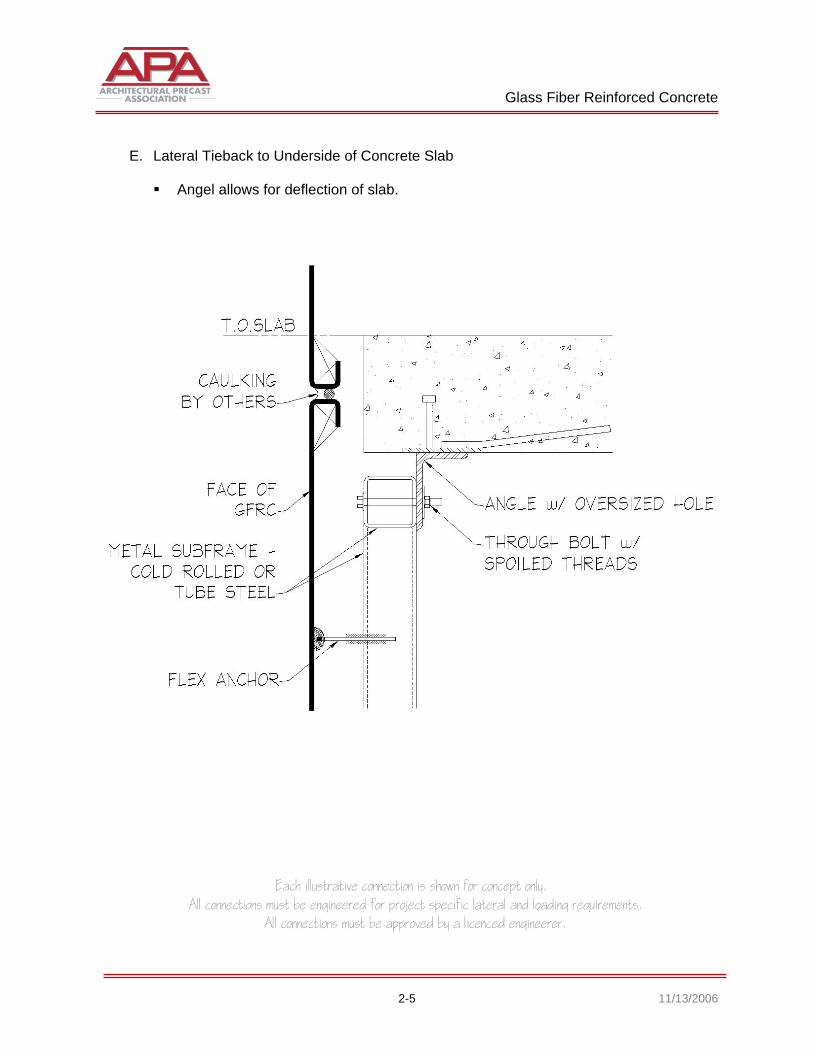
E. Lateral Tieback to Underside of Concrete Slab
Angel allows for deflection of slab.
Glass Fiber Reinforced Concrete
Each illustrative connection is shown for concept only. All connections must be engineered for project specific lateral and loading requirements.
All connections must be approved by a licenced engineerer.
2-6 11/13/2006
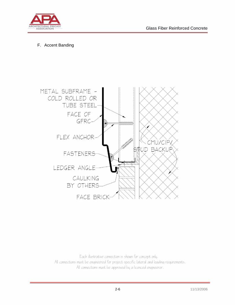
F. Accent Banding
Glass Fiber Reinforced Concrete
Each illustrative connection is shown for concept only. All connections must be engineered for project specific lateral and loading requirements.
All connections must be approved by a licenced engineerer.
2-7 11/13/2006
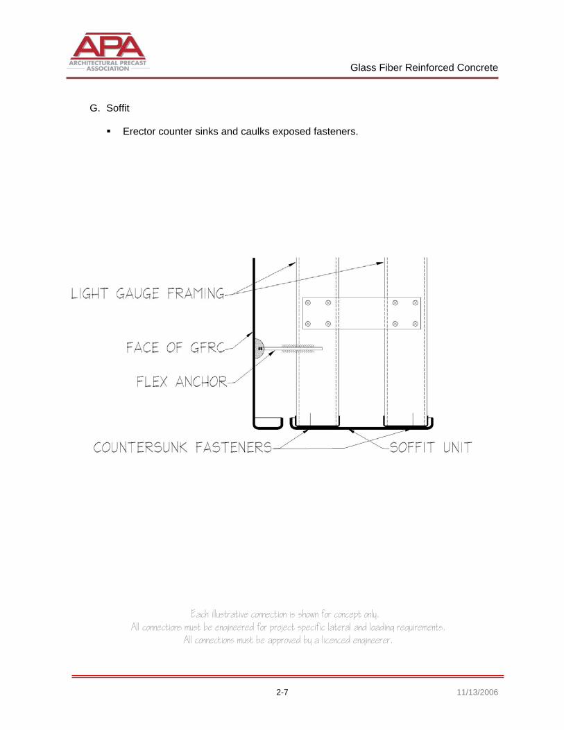
G. Soffit
Erector counter sinks and caulks exposed fasteners.
PART 3
Cast Stone

Cast Stone
Each illustrative connection is shown for concept only. All connections must be engineered for project specific lateral and loading requirements.
All connections must be approved by a licenced engineerer.
3-1 11/13/2006
PART 3 - CAST STONE
3.1 CONNECTIONS A. Accent Banding Without Mechanical Fasteners
Laid in place with mortar.
Cast Stone
Each illustrative connection is shown for concept only. All connections must be engineered for project specific lateral and loading requirements.
All connections must be approved by a licenced engineerer.
3-2 11/13/2006
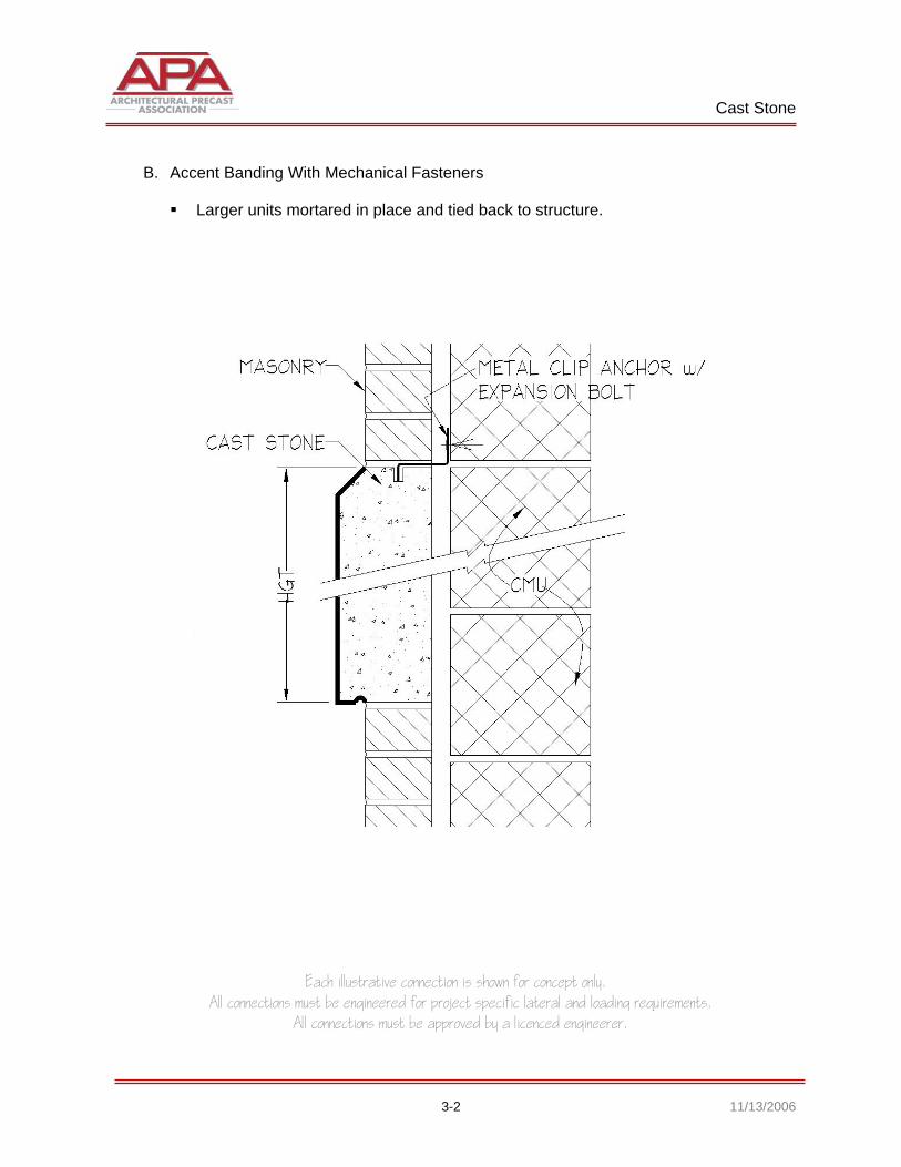
B. Accent Banding With Mechanical Fasteners
Larger units mortared in place and tied back to structure.

Cast Stone
Each illustrative connection is shown for concept only. All connections must be engineered for project specific lateral and loading requirements.
All connections must be approved by a licenced engineerer.
3-3 11/13/2006
C. Window Sill

Cast Stone
Each illustrative connection is shown for concept only. All connections must be engineered for project specific lateral and loading requirements.
All connections must be approved by a licenced engineerer.
3-4 11/13/2006
D. Window Lintels
Using relieving angels.
Cast Stone
Each illustrative connection is shown for concept only. All connections must be engineered for project specific lateral and loading requirements.
All connections must be approved by a licenced engineerer.
3-5 11/13/2006
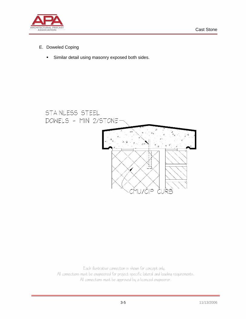
E. Doweled Coping
Similar detail using masonry exposed both sides.
Cast Stone
Each illustrative connection is shown for concept only. All connections must be engineered for project specific lateral and loading requirements.
All connections must be approved by a licenced engineerer.
3-6 11/13/2006
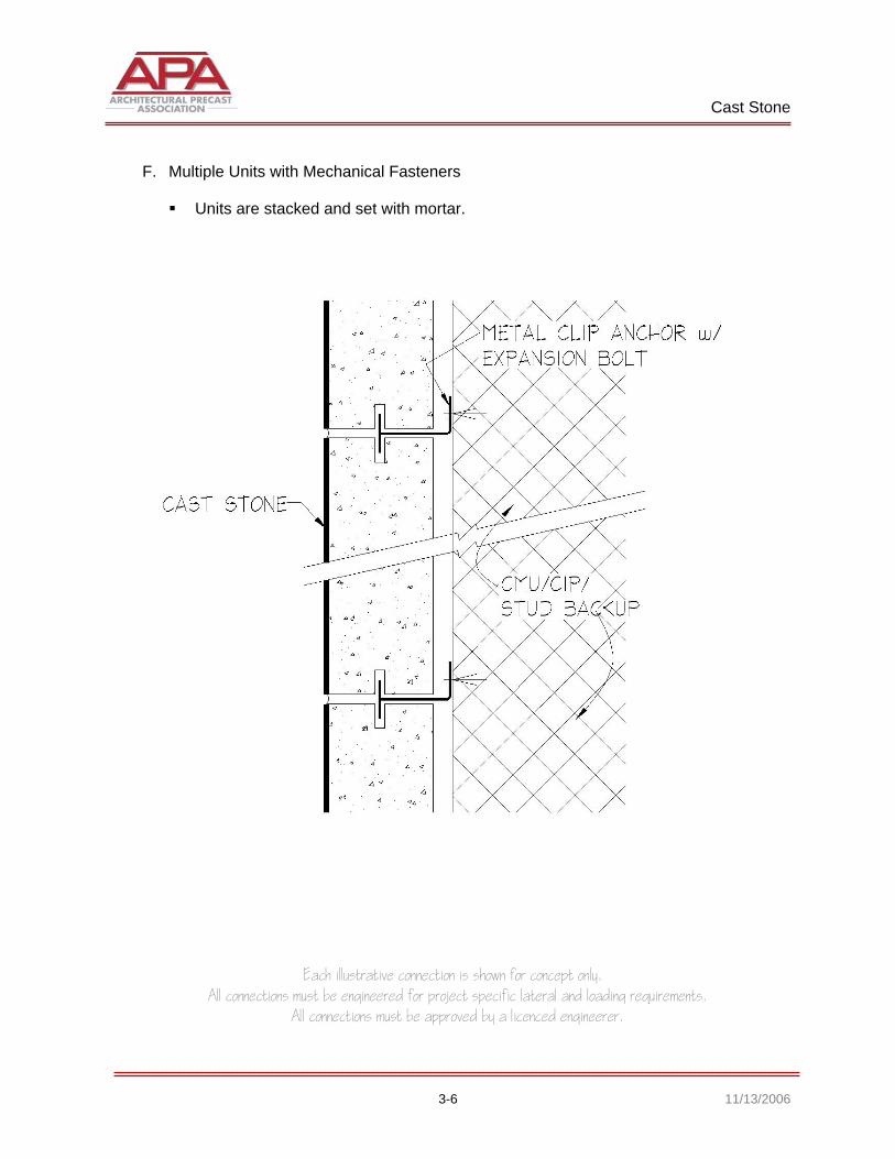
F. Multiple Units with Mechanical Fasteners
Units are stacked and set with mortar.

Cast Stone
Each illustrative connection is shown for concept only. All connections must be engineered for project specific lateral and loading requirements.
All connections must be approved by a licenced engineerer.
3-7 11/13/2006
G. Parapet - Control Joints
Control joints are caulked by others with sealant.
Cast Stone
Each illustrative connection is shown for concept only. All connections must be engineered for project specific lateral and loading requirements.
All connections must be approved by a licenced engineerer.
3-8 11/13/2006
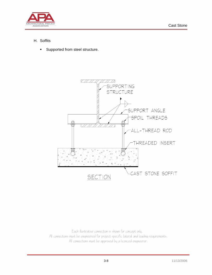
H. Soffits
Supported from steel structure.

Cast Stone
Each illustrative connection is shown for concept only. All connections must be engineered for project specific lateral and loading requirements.
All connections must be approved by a licenced engineerer.
3-9 11/13/2006
I. Watertable
Doweled, grouted and mechanically fastened.

Architectural Precast Association | 6710 Winkler Road, Suite 8 | Fort Myers, FL 33919 Phone: 239-454-6989 | Fax: 239-454-6787 | E-mail: [email protected]