Embed Size (px)
Citation preview

Operating Instructions
Betriebsanleitung
Mode d’emploi
Modo d’uso
Measure what you see.
Conical Mandrel Bending TesterDornbiegeprüfer mit konischem Dorn


EDFI
205 012 573 1806
Conical Mandrel Bending Tester
Catalog No. 5751
Dornbiegeprüfer mit konischem Dorn
Bestellnummer 5751
Mandrin de pliage conique
N° Réf. 5751
Mandrino Conico
No di cat. 5751


Conical Mandrel Bending Tester
Catalog No. 5751
Contents
1. General
2. Measurement Procedure
3. Components / Ordering Guide
Technical data are subject to alterations.


Bending a coated sheet metal overa defi ned radius allows an indica-tion of the elongation and adhesion of a paint fi lm at bending stress. The ASTM and ISO standards describe the test method by means of a conical mandrel. The use of a conical mandrel bending tester enables testing of a large variety of bending radiuses at the same time.
The conical mandrel consists of an20 cm (8 in.) long metal cone with a diameter decreasing from 38 mm(1 1/2 in.) to 3.2 mm (1/8 in.).
The mandrel is mounted on a baseplate in a horizontal position. Anoperating lever with a drawbar isprovided for bending the test panel around the mandrel. The instrument is also equipped with a device for clamping the test panel.
1. General Test in accordance with
ASTM D 1737
withdrawn in 1988 and replaced by:
ASTM D522DIN 53150
DIN EN ISO 1519
DIN EN ISO 6860.
Fig. 1 Bend Test

Evaluation of the Test Panel
Examine the coating immediately for cracking and / or detachment from the substrate either with the unaided eye or, by agreement, with a lens of 10 x magnification.
The length of the extent of cracking is measured in cm or inch along the test panel from the small end of the mandrel. Calculate the mean value of three tests and report the result to the nearest centimeter.
On the edges of the clamp plate is a ruler in centimeters on one side and a ruler in inches on the other side. On the mandrel‘s base is a ruler that has centimeter and inch lengths and the mandrel‘s diameter at specific lengths.
For a procedure evaluation consult the DIN EN ISO or ASTM standards.
2. Measurement Procedure • Place the bending lever into its lowest position with the lever in front of the Tester.
• Slip the test panel with the coa-ted side towards the drawbar between mandrel and drawbar and in such a position that one short edge touches the narrow end of the mandrel (smallest diameter).
• Position the test panel between the clamp plate and Tester base. Tighten the panel by tur-ning the cam clockwise for thin panels and counter-clockwise for thick panels.
• Move the bending lever conti-nuously to the upper position, thus bending the test panel over the mandrel through 180° in about 2-3 sec. (15 sec. accor-ding to ASTM).
• Mark the point at which the cracking stops.

Ordering Guide
Catalog No. 5751
3. Components / Ordering Guide Components
Conical Mandrel Base is a powder- coated steel with the cone, roller, and clamp plate is made of stain-less steel
Measuring range: 1/8 to 1 1/2 in. (3.2 to 38 mm) mandrel diameter

Dornbiegeprüfer mit konischem Dorn
Bestellnummer 5751
Inhaltsverzeichnis
1. Allgemeines
2. Messung
3. Lieferumfang / Lieferhinweise
Technische Änderungen vorbehalten.


Das Abbiegen eines lackiertenBlechstreifens über einen bestimm-ten Radius gestattet eine Aussageüber die Dehnbarkeit und Haft- festigkeit eines Lackfilms bei Biege- beanspruchung. In der ASTM und ISO Norm wird die Prüfung mit einem konischen Dorn beschrieben. Mit dem Dornbiegeprüfer konisch lässt sich mit einer Prüfung ein ganzer Bereich unterschiedlicher Biege- radien erfassen.
Der konische Dorn besteht auseinem 20 cm (8 in.) langen Kegel-stumpf. Der Durchmesser ist abneh-mend von 38 mm (1 1/2 in.) auf 3.2 mm (1/8 in.)
Der Dorn ist waagerecht auf einerGrundplatte befestigt. Ein Bedie-nungsgriff mit Ziehwalze ist zum Biegen des Prüfbleches um den Dorn vorgesehen. Am Prüfgerätist auch eine Vorrichtung zum Fest-spannen des Prüfbleches ange-bracht.
1. Allgemeines Prüfung nach
ASTM D 1737
1988 zurückgenommen und ersetzt durch:
ASTM D522DIN 53150
DIN EN ISO 1519
DIN EN ISO 6860.

Abb. 1 Dornbiegeversuch

Beurteilung der Probeplatte
Sofort danach wird die Beschich-tung auf Rissbildung und/oderAblösen vom Untergrund, entwe-der mit bloßem Auge oder – nach Vereinbarung – mit einer Lupe von 10facher Vergrößerung untersucht.
Die Länge des Risses wird vomdünnen Ende des Dorns aus entlangder Probeplattenoberfläche incm gemessen. Aus drei Prüfungenist der Mittelwert zu bilden. Das Er-gebnis wird auf ganze cm gerundetangegeben.
An den Rändern der Klemmplatte befindet sich auf der einen Seite ein Lineal in Zentimetern und auf der anderen Seite ein Lineal in Zoll. Der Durchmesser des Dorns steht unterhalb des Dorns.
Achtung: Die Prüfung und Auswer-tung ist unter Zuhilfenahme der DIN EN ISO bzw. ASTM Normen durch-zuführen.
2. Messung • Biegehebel in die untere, hori-zontale Position bringen.
• Es ist ratsam, die beschichtete Seite des Prüfbleches mit einem Blatt Papier abzudecken, um mechanische Verletzungen des Films zu vermeiden.
• Positionieren Sie das Prüfblech zwischen der Klemmplatte und dem Prüfgerät.
• Den Feststellhebel durch Verdrehen so einstellen, dass durch Andrücken des Hebels das Prüfstück fest zwischen Klemmplatte und dem Prüfgerät fixiert wird.
• Biegehebel gleichmäßig inner-halb von etwa 2-3 Sekunden (15 Sekunden nach ASTM) um ca. 180° nach oben um den koni-schen Dorn ziehen und damit das Prüfblech biegen.
• Die Stelle markieren, an der die Rissbildung aufhört.

Lieferhinweise
Katalog-Nr. 5751
3. Lieferumfang / Lieferhinweise Lieferumfang
Dornbiegeprüfer konisch. Die Basis des Prüfgerätes ist aus pulverbeschichtetem Stahl; Koni-scher Dorn, Rolle, Biegehebel und Klemmplatte aus Edelstahl.
Messbereich: 1/8 in. bis 1 1/2 in. (3,2 bis 38 mm) Dorndurchmesser

Mandrin de pliage conique
N° Réf. 5751
Table des matières
1. Informations générales
2. Mode opératoire
3. Fourniture / Informations sur la livraison
Sous réserve de modifications techniques.


Le pliage d‘une bande de tôle vernie sur un diamètre défini permet d‘examiner l‘aptitude à l‘allongement et la propriété adhé-sive d‘une peinture sous contrainte de flexion. Les normes ASTM et ISO décrivent l‘essai de pliage sur man-drin conique. A l‘aide du mandrin conique il est possible de couvrir une étendue de diamètre de pliage différent par un seul essai.
Le mandrin conique consiste en un cône tronqué 8 in. (20 cm) de long,d‘un diamètre diminuant de 1 1/2 in. (38 mm) à 1/8 in. (3,2 mm).
Le mandrin est monté dans une po-sition horizontale sur une embase. A l‘aide d‘une poignée de manoeu-vre le panneau d‘essai est plié sur le mandrin. L‘appareil est en outre muni d‘un dispositif pour serrer le panneau d‘essai.
1. Informations générales Essai selon les normes
ASTM D 1737
a été annulée 1988 et remplacée par :
ASTM D522DIN 53150
DIN EN ISO 1519
DIN EN ISO 6860.

Fig. 1 Essai de pliage

Evaluation de la pièce
Examiner immédiatement l‘échantillon pour constater l‘apparition de craquelures ou de décollement du film, à l’œil nu ou suivant accord, en utilisant une lentille de grossissement x10.
Noter la longueur des craquelu-res en cm ou en inch à partir du diamètre minimal du mandrin le long du panneau. Calculer la moyenne de trois résultats obtenus. Indiquer le résultat arrondi en cm .
Sur les bords de la plaque de ser-rage se trouve une règle en cen-timètres d‘un côté et une règle en pouces de l‘autre côté.
2. Mode opératoire • Placer le levier de pliage dans sa position la plus basse.
• Couvrir votre pièce avec du pa-pier pour éviter un dégât du film.
• Placer un papier entre le mandrin et votre pièce le côté vernis en direction de votre pièce pour que le bord court de la pièce touche le diamètre le plus fin du man-drin.
• Placer la pièce entre la plaque de serrage et la base. Serrer la en tournant la came dans le sens horaire pour les pièces fines et dans le sens antihoraire pour les pièces épaisses.
• Relever la poignée régulièrement en pliant ainsi à 180° la pièce sur le mandrin, la durée du mouve-ment étant 2 - 3 sec. (15 sec. selon ASTM).
• Marquer le point où on ne peut plus constater de craquelures.

Informations sur la livraison
N° Réf. 5751
3. Fourniture / Informations sur la livraison
Fourniture
La base de mandrin conique est un acier peint de peinture poudre. Le cône, le rouleau, et la plaque de serrage sont faits d‘acier inoxy-dable.
Gamme de mesure du diamètre du mandrin: 1/8 in. à 1 1/2 in. (3,2 à 38 mm)
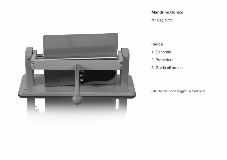
Mandrino Conico
N° Cat. 5751
Indice
1. Generale
2. Procedura
3. Guida all‘ordine
I dati tecnici sono soggetti a modifiche.


La piegatura di una lamiera di me-tallo verniciato su un raggio definito dà un’indicazione dell’allungamento e l’adesione di un film di vernice sotto stress di piegatura. Le norme ASTM e ISO descrivono il metodo di prova per mezzo di un mandrino conico. L’uso di un mandrino conico permette la prova su una grande varietà di raggi di piegatura nello stesso tempo.
Il mandrino conico consiste di un cono di metallo lungo 20 cm (8 in.) con un diametro decrescente da 38 mm (1 ½ in.) a 3.2 mm (1/8 in.)
Il mandrino viene montato su un piatto base in posizione orizzontale. Viene fornita una leva operatrice con una barra per piegare il pannel-lo intorno al mandrino. Lo strumento è anche fornito di un dispositivo per il bloccaggio del pannello di prova.
1. Generale Il metodo di prova è conforme alla
ASTM D 1737
revocata nel 1988 e sostituito da:
ASTM D522DIN 53150
DIN EN ISO 1519
DIN EN ISO 6860.

Fig. 1 Test di piegatura

Valutazione del pannello di prova
Esaminare immediatamente la vernice per le crepe e/o il distacco o ad occhio nudo o, convenzional-mente, con una lente 10x.
La lunghezza dell’estensione della crepa viene misurata in cm o in. lungo il pannello di prova dalla parte più piccola del mandrino. Calco-lare il valore medio di tre prove e riportare il risultato al centimetro più vicino.
Per una valutazione della procedura consultare le norme DIN EN ISO o ASTM.
2. Procedura • La leva deve essere di fronte all’operatore ed abbassarla nella posizione più bassa
• Si raccomanda di coprire la parte verniciata del pannello di prova con un foglio di carta per evitare danni meccanici al film.
• Fare scivolare il pannello di pro-va con la parte verniciata (vedi foto 1), in posizione tale che un bordo tocchi il diametro più stretto del mandrino.
• Posizionare il pannello di pro-va tra il piatto e la base dello strumento. Stringere il pannello girando la camma in senso ora- rio per pannelli sottili e in senso antiorario per pannelli spessi.
• Muovere la leva piegatrice in ma-niera continua e uniforme nella posizione superiore, piegando così il pannello di prova per circa 180° per 2-3 sec. (15 sec. in accordo ASTM).
• Marcare il punto in cui la crepa termina.

No di cat. 57513. Guida all‘ordine Strumento di piegatura con man-drino conico. La base è in acciaio verniciato in polvere con il cono, la barra e la pinza in acciaio inossida-bile.
Campo di misura: diametro del mandrino da 1/8 in a 1 ½ in. (da 3.2 a 38 mm)

BYK-Gardner USA
9104 Guilford Road Columbia, MD 21046 USA
Phone 800 343-7721 301 483-6500
Fax 800 394-8215 301 483-6555
BYK-Gardner GmbH
Lausitzer Straße 8 D-82538 Geretsried Germany
Tel 0 800 gardner (0 800 4273637) +49 8171 3493-0
Fax +49 8171 3493-140
www.byk.com/instruments/


205 012 573 EDFI 1806