Embed Size (px)
Citation preview
Cisco IAD2430 Series IntegrOL-4306-03
C H A P T E R 3
Configuring with the Command-Line InterfaceThis chapter describes how to use the Cisco IOS software command-line interface (CLI) to configure basic Cisco integrated access device (IAD) functionality.
This chapter presents the following major topics:
• Configuring the Hostname and Password, page 3-2
• Configuring Fast Ethernet Interfaces, page 3-4
• Configuring Network Clock, page 3-5
• Configuring T1/E1 Interfaces, page 3-7
• Configuring a WIC-1DSU-T1/E1 Serial WAN Interface Card, page 3-21
• Configuring a WIC-1T or WIC-2T Serial WAN Interface Card, page 3-24
• Configuring a VIC2-2FXO or VIC2-4FXO Voice Interface Card, page 3-25
• Configuring a VIC2-2FXS or VIC2-4FXS Voice Interface Card, page 3-27
• Configuring ATM T1-WAN Ports, page 3-29
• Configuring 1-Port ADSL/SHDSL WAN Interface Card, page 3-33
• Configuring a VIC2-2BRI-NT/TE Card, page 3-37
• Saving Configuration Changes, page 3-39
Follow the procedures in this chapter to configure the Cisco IAD manually or, if you wish, to change the configuration after you have run the setup command facility (see the “The setup Command Facility” section on page 2-2).
This chapter does not describe every configuration possible—only a small portion of the most commonly used configuration procedures. For advanced configuration topics, see the Cisco IOS configuration guide and command reference publications. See the “Obtaining Documentation and Submitting a Service Request” section on page -ix.
Note If you skipped Chapter 2, “Using the setup Command Facility,” and you have never configured a Cisco IAD, return to Chapter 2, “Using the setup Command Facility,” and read it now. The chapter contains important information that you need for configuring your Cisco IAD.
Note The Cisco IAD2435 router is a fixed-configuration router and does not support interface cards.
3-1ated Access Devices Software Configuration Guide
Chapter 3 Configuring with the Command-Line Interface Configuring the Hostname and Password
Note The Cisco IAD2435 IAD does not support loss plan or idle voltage features available on other Cisco IAD2430 series IADs.
Configuring the Hostname and PasswordOne of the first configuration tasks is to configure the hostname and set an encrypted password. Configuring a hostname allows you to distinguish multiple Cisco IADs and routers from each other. Setting an encrypted password allows you to prevent unauthorized configuration changes.
Note A hostname can be specified only when the router has a DNS server available for hostname resolution.
To configure the hostname and password, perform the following steps.
SUMMARY STEPS
1. enable
2. configure terminal
3. hostname
4. enable secret password
5. line-console
6. exec-timeout
7. exit
8. end
DETAILED STEPS
Command or Action Purpose
Step 1 enable
Example:Router# enable
Enters privileged EXEC mode.
Step 2 configure terminal
Example:Router# configure terminal
Enters global configuration mode.
Step 3 hostname
Example:Router(config)# hostname IAD2430
Changes the name of the Cisco IAD to a meaningful name.
3-2Cisco IAD2430 Series Integrated Access Devices Software Configuration Guide
OL-4306-03
Chapter 3 Configuring with the Command-Line Interface Configuring the Hostname and Password
Verifying the Hostname and PasswordTo verify that you configured the correct hostname and password, follow these steps:
Step 1 Enter the show config command:
Router(config)# show config
Using 1888 out of 126968 bytes!version XX.X...!hostname IAD2430!enable secret 5 $1$60L4$X2JYOwoDc0.kqa1loO/w8/...
Check the hostname and encrypted password displayed near the top of the command output.
Step 4 enable secret password
Example:Router(config)# enable secret guessme
Enters an enable secret password. This password provides access to privileged EXEC mode. When you press Enter at the user EXEC prompt (Router>), you must enter the enable secret password to gain access to configuration mode. Substitute your enable secret password for guessme.
Step 5 line console
Example:Router(config)# line console 0
Enters line configuration mode to configure the console port. When you enter line configuration mode, the prompt changes to Router(config-line)#.
Step 6 exec-timeout
Example:Router(config-line)# exec-timeout 0 0
If no input is detected during the interval, the EXEC facility resumes the current connection. If no connections exist, the EXEC facility returns the terminal to the idle state and disconnects the incoming session.
Note To specify no timeout, enter the exec-timeout 0 0 command.
Step 7 exit
Example:Router(config-line)# exit
Exits to global configuration mode.
Step 8 end
Example:Router(config-if)# end
Returns you to privileged EXEC mode.
Command or Action Purpose
3-3Cisco IAD2430 Series Integrated Access Devices Software Configuration Guide
OL-4306-03
Chapter 3 Configuring with the Command-Line Interface Configuring Fast Ethernet Interfaces
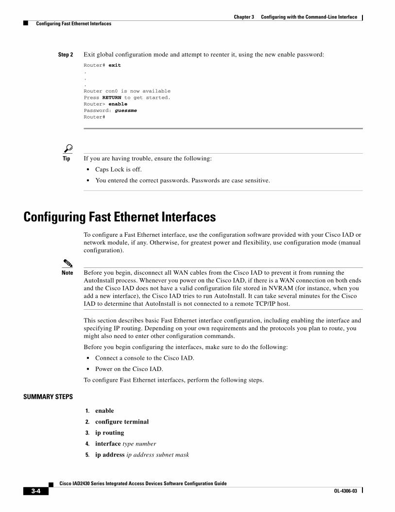
Step 2 Exit global configuration mode and attempt to reenter it, using the new enable password:
Router# exit...Router con0 is now availablePress RETURN to get started.Router> enablePassword: guessmeRouter#
Tip If you are having trouble, ensure the following:
• Caps Lock is off.
• You entered the correct passwords. Passwords are case sensitive.
Configuring Fast Ethernet InterfacesTo configure a Fast Ethernet interface, use the configuration software provided with your Cisco IAD or network module, if any. Otherwise, for greatest power and flexibility, use configuration mode (manual configuration).
Note Before you begin, disconnect all WAN cables from the Cisco IAD to prevent it from running the AutoInstall process. Whenever you power on the Cisco IAD, if there is a WAN connection on both ends and the Cisco IAD does not have a valid configuration file stored in NVRAM (for instance, when you add a new interface), the Cisco IAD tries to run AutoInstall. It can take several minutes for the Cisco IAD to determine that AutoInstall is not connected to a remote TCP/IP host.
This section describes basic Fast Ethernet interface configuration, including enabling the interface and specifying IP routing. Depending on your own requirements and the protocols you plan to route, you might also need to enter other configuration commands.
Before you begin configuring the interfaces, make sure to do the following:
• Connect a console to the Cisco IAD.
• Power on the Cisco IAD.
To configure Fast Ethernet interfaces, perform the following steps.
SUMMARY STEPS
1. enable
2. configure terminal
3. ip routing
4. interface type number
5. ip address ip address subnet mask
3-4Cisco IAD2430 Series Integrated Access Devices Software Configuration Guide
OL-4306-03
Chapter 3 Configuring with the Command-Line Interface Configuring Network Clock
6. exit
7. Ctrl-z
DETAILED STEPS
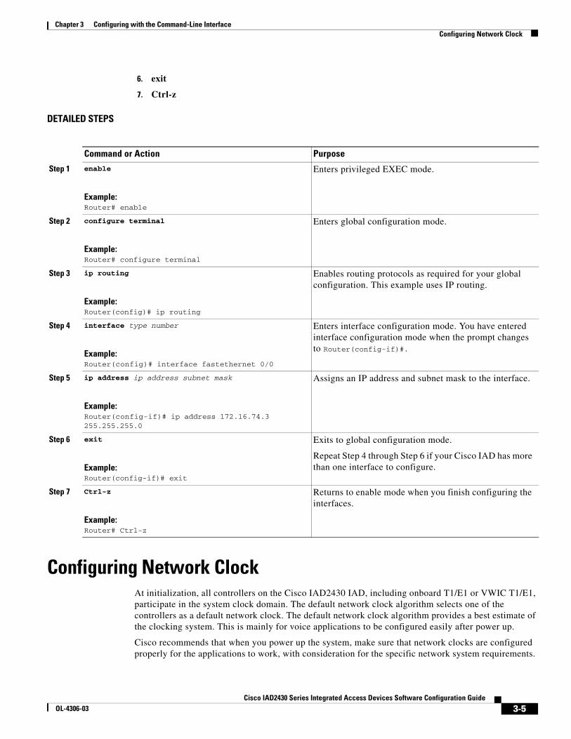
Configuring Network ClockAt initialization, all controllers on the Cisco IAD2430 IAD, including onboard T1/E1 or VWIC T1/E1, participate in the system clock domain. The default network clock algorithm selects one of the controllers as a default network clock. The default network clock algorithm provides a best estimate of the clocking system. This is mainly for voice applications to be configured easily after power up.
Cisco recommends that when you power up the system, make sure that network clocks are configured properly for the applications to work, with consideration for the specific network system requirements.
Command or Action Purpose
Step 1 enable
Example:Router# enable
Enters privileged EXEC mode.
Step 2 configure terminal
Example:Router# configure terminal
Enters global configuration mode.
Step 3 ip routing
Example:Router(config)# ip routing
Enables routing protocols as required for your global configuration. This example uses IP routing.
Step 4 interface type number
Example:Router(config)# interface fastethernet 0/0
Enters interface configuration mode. You have entered interface configuration mode when the prompt changes to Router(config-if)#.
Step 5 ip address ip address subnet mask
Example:Router(config-if)# ip address 172.16.74.3 255.255.255.0
Assigns an IP address and subnet mask to the interface.
Step 6 exit
Example:Router(config-if)# exit
Exits to global configuration mode.
Repeat Step 4 through Step 6 if your Cisco IAD has more than one interface to configure.
Step 7 Ctrl-z
Example:Router# Ctrl-z
Returns to enable mode when you finish configuring the interfaces.
3-5Cisco IAD2430 Series Integrated Access Devices Software Configuration Guide
OL-4306-03
Chapter 3 Configuring with the Command-Line Interface Configuring Network Clock
To view the current primary clock, use the show network-clocks or show run command. Note that the show network-clocks and show run commands do not display the default network clock, which is selected by the default network clock algorithm.
To have the T1/E1 controller participate as a clock source for the Cisco IAD system clock domain and to make sure it is available as a candidate for a clock selection algorithm, use the following CLI configuration. If you have data applications that do not require clock participation, use the no form of the commands.
To configure the network clock, perform the following steps.
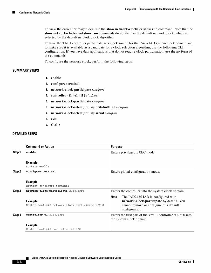
SUMMARY STEPS
1. enable
2. configure terminal
3. network-clock-participate slot/port
4. controller {t1 | e1 | j1} slot/port
5. network-clock-participate slot/port
6. network-clock-select priority bri|atm|t1|e1 slot/port
7. network-clock-select priority serial slot/port
8. exit
9. Ctrl-z
DETAILED STEPS
Command or Action Purpose
Step 1 enable
Example:Router# enable
Enters privileged EXEC mode.
Step 2 configure terminal
Example:Router# configure terminal
Enters global configuration mode.
Step 3 network-clock-participate slot/port
Example:Router(config)# network-clock-participate WIC 0
Enters the controller into the system clock domain.
Note The IAD2435 IAD is configured with network-clock-participate by default. You cannot remove or configure this default configuration.
Step 4 controller t1 slot/port
Example:Router(config)# controller t1 0/2
Enters the first part of the VWIC controller at slot 0 into the system clock domain.
3-6Cisco IAD2430 Series Integrated Access Devices Software Configuration Guide
OL-4306-03
Chapter 3 Configuring with the Command-Line Interface Configuring T1/E1 Interfaces
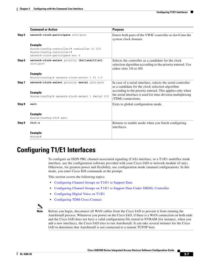
Configuring T1/E1 InterfacesTo configure an ISDN PRI, channel-associated signaling (CAS) interface, or a T1/E1 multiflex trunk interface, use the configuration software provided with your Cisco IAD or network module (if any). Otherwise, for greatest power and flexibility, use configuration mode (manual configuration). In this mode, you enter Cisco IOS commands at the prompt.
This section covers the following topics:
• Configuring Channel Groups on T1/E1 to Support Data
• Configuring Channel Groups on T1/E1 to Support Data Under SHDSL Controller
• Configuring Digital Voice on T1/E1
• Configuring TDM Cross-Connect
Note Before you begin, disconnect all WAN cables from the Cisco IAD to prevent it from running the AutoInstall process. Whenever you power on the Cisco IAD, if there is a WAN connection on both ends and the Cisco IAD does not have a valid configuration file stored in NVRAM (for instance, when you add a new interface), the Cisco IAD tries to run AutoInstall. It can take several minutes for the Cisco IAD to determine that AutoInstall is not connected to a remote TCP/IP host.
Step 5 network-clock-participate slot/port
Example:Router(config-controller)# controller t1 0/2Router(config-controller)# network-clock-participate wic 0
Enters both parts of the VWIC controller at slot 0 into the system clock domain.
Step 6 network-clock-select priority {bri|atm|t1|e1} slot/port
Example:Router(config)# network-clock-select 1 T1 1/0
Selects the controller as a candidate for the clock selection algorithm according to the priority entered. Use either slots 1/0 or 0/0.
Step 7 network-clock-select priority serial slot/port
Example:Router(config)# network-clock-select 1 Serial 0/0
In case of a serial interface, selects the serial controller as a candidate for the clock selection algorithm according to the priority entered. This applies only when the serial interface is used for time-division multiplexing (TDM) connections.
Step 8 exit
Example:Router(config-if)# exit
Exits to global configuration mode.
Step 9 Ctrl-z
Example:Router#
Returns to enable mode when you finish configuring interfaces.
Command or Action Purpose
3-7Cisco IAD2430 Series Integrated Access Devices Software Configuration Guide
OL-4306-03
Chapter 3 Configuring with the Command-Line Interface Configuring T1/E1 Interfaces
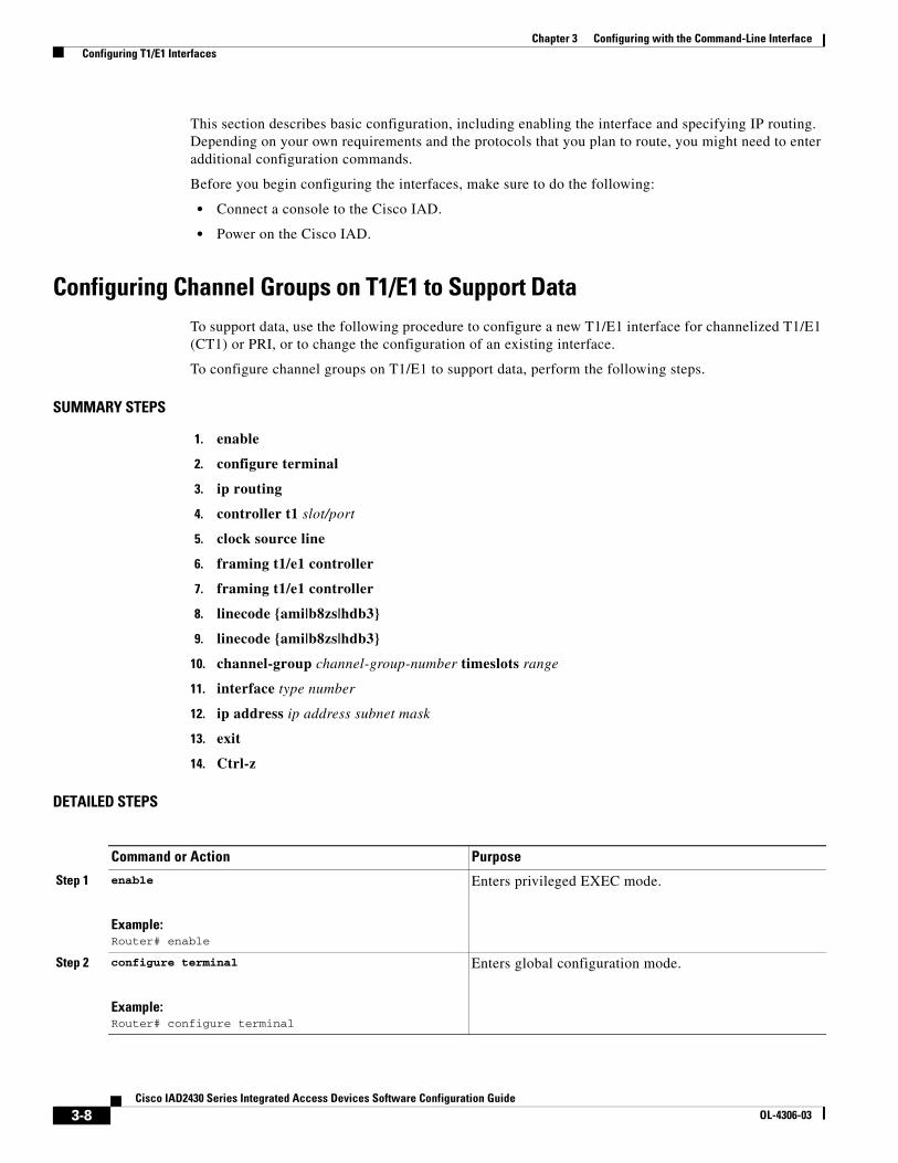
This section describes basic configuration, including enabling the interface and specifying IP routing. Depending on your own requirements and the protocols that you plan to route, you might need to enter additional configuration commands.
Before you begin configuring the interfaces, make sure to do the following:
• Connect a console to the Cisco IAD.
• Power on the Cisco IAD.
Configuring Channel Groups on T1/E1 to Support DataTo support data, use the following procedure to configure a new T1/E1 interface for channelized T1/E1 (CT1) or PRI, or to change the configuration of an existing interface.
To configure channel groups on T1/E1 to support data, perform the following steps.
SUMMARY STEPS
1. enable
2. configure terminal
3. ip routing
4. controller t1 slot/port
5. clock source line
6. framing t1/e1 controller
7. framing t1/e1 controller
8. linecode {ami|b8zs|hdb3}
9. linecode {ami|b8zs|hdb3}
10. channel-group channel-group-number timeslots range
11. interface type number
12. ip address ip address subnet mask
13. exit
14. Ctrl-z
DETAILED STEPS
Command or Action Purpose
Step 1 enable
Example:Router# enable
Enters privileged EXEC mode.
Step 2 configure terminal
Example:Router# configure terminal
Enters global configuration mode.
3-8Cisco IAD2430 Series Integrated Access Devices Software Configuration Guide
OL-4306-03
Chapter 3 Configuring with the Command-Line Interface Configuring T1/E1 Interfaces
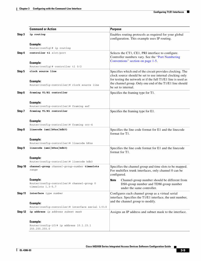
Step 3 ip routing
Example:Router(config)# ip routing
Enables routing protocols as required for your global configuration. This example uses IP routing.
Step 4 controller t1 slot/port
Example:Router(config)# controller t1 0/2
Selects the CT1, CE1, PRI interface to configure. Controller numbers vary. See the “Port Numbering Conventions” section on page 1-5.
Step 5 clock source line
Example:Router(config-controller)# clock source line
Specifies which end of the circuit provides clocking. The clock source should be set to use internal clocking only for testing the network or if the full T1/E1 line is used as the channel group. Only one end of the T1/E1 line should be set to internal.
Step 6 framing T1/E1 controller
Example:Router(config-controller)# framing esf
Specifies the framing type for T1.
Step 7 framing T1/E1 controller
Example:Router(config-controller)# framing crc-4
Specifies the framing type for E1.
Step 8 linecode {ami|b8zs|hdb3}
Example:Router(config-controller)# linecode b8zs
Specifies the line code format for E1 and the linecode format for T1.
Step 9 linecode {ami|b8zs|hdb3}
Example:Router(config-controller)# linecode hdb3
Specifies the line code format for E1 and the linecode format for T1.
Step 10 channel-group channel-group-number timeslots range
Example:Router(config-controller)# channel-group 0 timeslots 1,3-5,7
Specifies the channel group and time slots to be mapped. For multiflex trunk interfaces, only channel 0 can be configured.
Note Channel-group number should be different from DS0-group number and TDM-group number under the same controller.
Step 11 interface type number
Example:Router(config-controller)# interface serial 1/0:0
Configures each channel group as a virtual serial interface. Specifies the T1/E1 interface, the unit number, and the channel group to modify.
Step 12 ip address ip address subnet mask
Example:Router(config-if)# ip address 10.1.15.1 255.255.255.0
Assigns an IP address and subnet mask to the interface.
Command or Action Purpose
3-9Cisco IAD2430 Series Integrated Access Devices Software Configuration Guide
OL-4306-03
Chapter 3 Configuring with the Command-Line Interface Configuring T1/E1 Interfaces
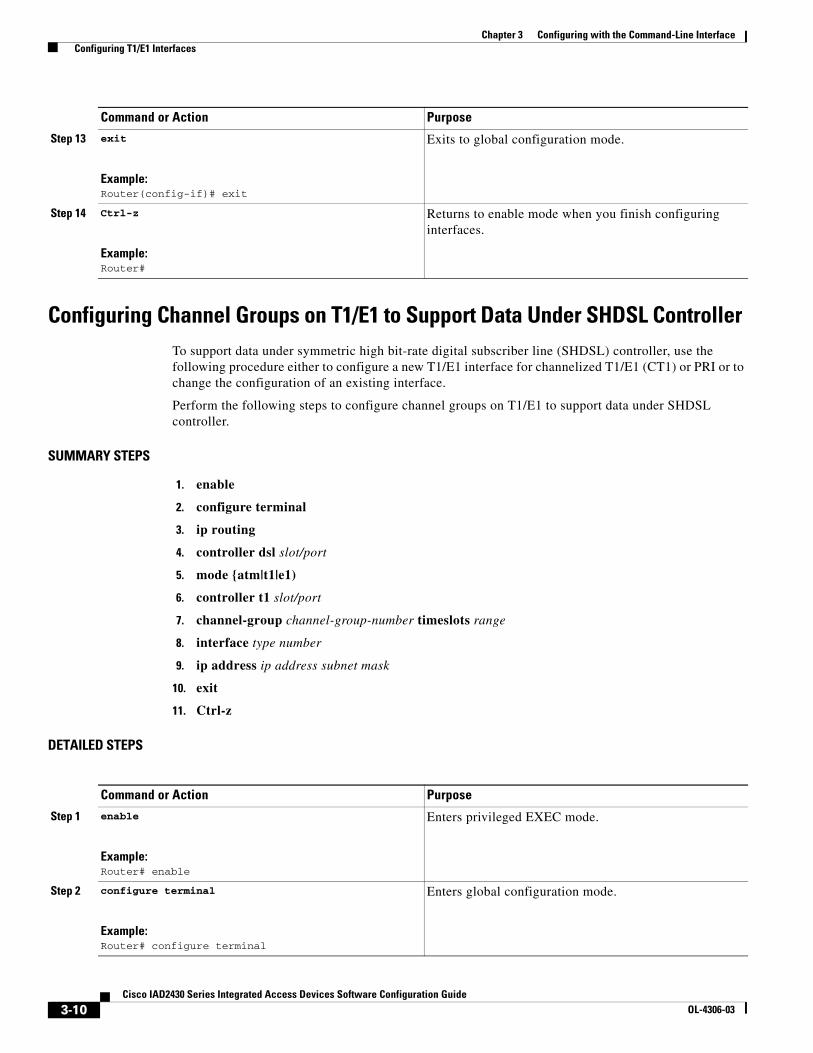
Configuring Channel Groups on T1/E1 to Support Data Under SHDSL ControllerTo support data under symmetric high bit-rate digital subscriber line (SHDSL) controller, use the following procedure either to configure a new T1/E1 interface for channelized T1/E1 (CT1) or PRI or to change the configuration of an existing interface.
Perform the following steps to configure channel groups on T1/E1 to support data under SHDSL controller.
SUMMARY STEPS
1. enable
2. configure terminal
3. ip routing
4. controller dsl slot/port
5. mode {atm|t1|e1)
6. controller t1 slot/port
7. channel-group channel-group-number timeslots range
8. interface type number
9. ip address ip address subnet mask
10. exit
11. Ctrl-z
DETAILED STEPS
Step 13 exit
Example:Router(config-if)# exit
Exits to global configuration mode.
Step 14 Ctrl-z
Example:Router#
Returns to enable mode when you finish configuring interfaces.
Command or Action Purpose
Command or Action Purpose
Step 1 enable
Example:Router# enable
Enters privileged EXEC mode.
Step 2 configure terminal
Example:Router# configure terminal
Enters global configuration mode.
3-10Cisco IAD2430 Series Integrated Access Devices Software Configuration Guide
OL-4306-03
Chapter 3 Configuring with the Command-Line Interface Configuring T1/E1 Interfaces
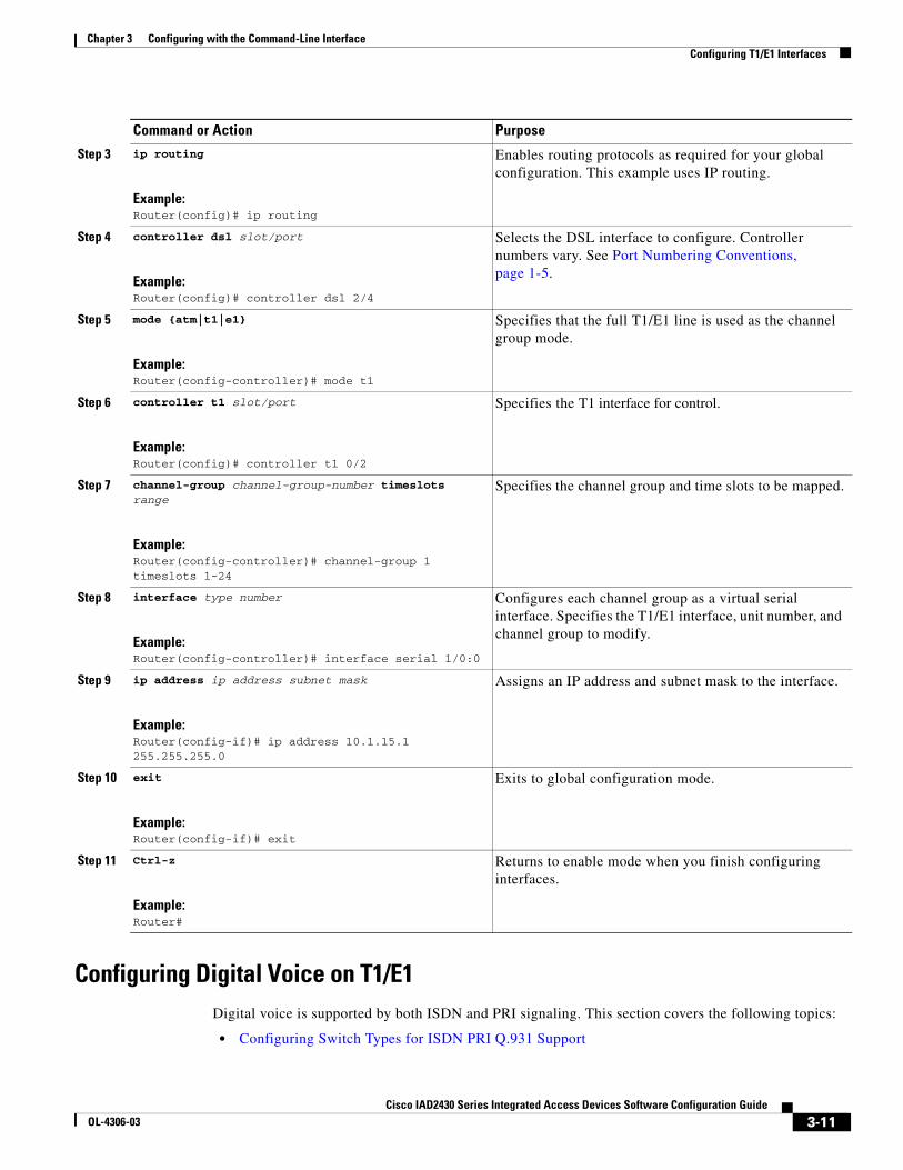
Configuring Digital Voice on T1/E1Digital voice is supported by both ISDN and PRI signaling. This section covers the following topics:
• Configuring Switch Types for ISDN PRI Q.931 Support
Step 3 ip routing
Example:Router(config)# ip routing
Enables routing protocols as required for your global configuration. This example uses IP routing.
Step 4 controller dsl slot/port
Example:Router(config)# controller dsl 2/4
Selects the DSL interface to configure. Controller numbers vary. See Port Numbering Conventions, page 1-5.
Step 5 mode {atm|t1|e1}
Example:Router(config-controller)# mode t1
Specifies that the full T1/E1 line is used as the channel group mode.
Step 6 controller t1 slot/port
Example:Router(config)# controller t1 0/2
Specifies the T1 interface for control.
Step 7 channel-group channel-group-number timeslots range
Example:Router(config-controller)# channel-group 1 timeslots 1-24
Specifies the channel group and time slots to be mapped.
Step 8 interface type number
Example:Router(config-controller)# interface serial 1/0:0
Configures each channel group as a virtual serial interface. Specifies the T1/E1 interface, unit number, and channel group to modify.
Step 9 ip address ip address subnet mask
Example:Router(config-if)# ip address 10.1.15.1 255.255.255.0
Assigns an IP address and subnet mask to the interface.
Step 10 exit
Example:Router(config-if)# exit
Exits to global configuration mode.
Step 11 Ctrl-z
Example:Router#
Returns to enable mode when you finish configuring interfaces.
Command or Action Purpose
3-11Cisco IAD2430 Series Integrated Access Devices Software Configuration Guide
OL-4306-03

Chapter 3 Configuring with the Command-Line Interface Configuring T1/E1 Interfaces
• Configuring DS0 Groups for CAS
For more information on configuring ISDN voice interfaces, see the Basic ISDN Voice-Interface Configuration document.
3-12Cisco IAD2430 Series Integrated Access Devices Software Configuration Guide
OL-4306-03
Chapter 3 Configuring with the Command-Line Interface Configuring T1/E1 Interfaces
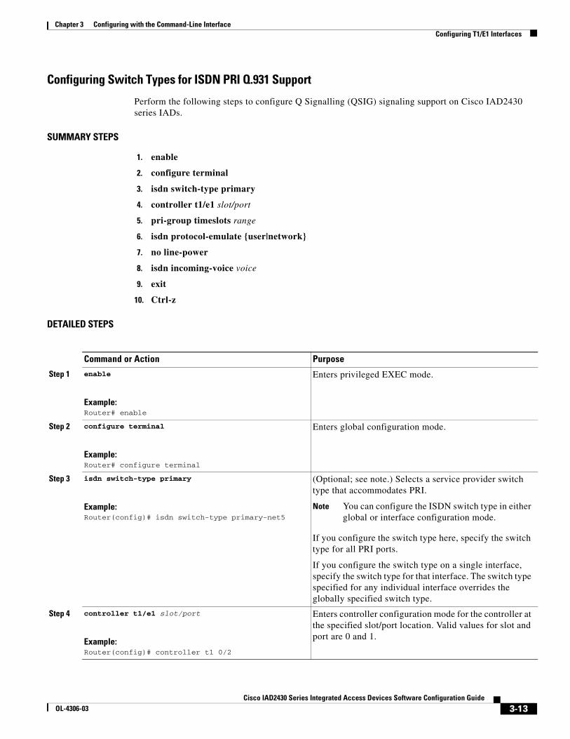
Configuring Switch Types for ISDN PRI Q.931 Support
Perform the following steps to configure Q Signalling (QSIG) signaling support on Cisco IAD2430 series IADs.
SUMMARY STEPS
1. enable
2. configure terminal
3. isdn switch-type primary
4. controller t1/e1 slot/port
5. pri-group timeslots range
6. isdn protocol-emulate {user|network}
7. no line-power
8. isdn incoming-voice voice
9. exit
10. Ctrl-z
DETAILED STEPS
Command or Action Purpose
Step 1 enable
Example:Router# enable
Enters privileged EXEC mode.
Step 2 configure terminal
Example:Router# configure terminal
Enters global configuration mode.
Step 3 isdn switch-type primary
Example:Router(config)# isdn switch-type primary-net5
(Optional; see note.) Selects a service provider switch type that accommodates PRI.
Note You can configure the ISDN switch type in either global or interface configuration mode.
If you configure the switch type here, specify the switch type for all PRI ports.
If you configure the switch type on a single interface, specify the switch type for that interface. The switch type specified for any individual interface overrides the globally specified switch type.
Step 4 controller t1/e1 slot/port
Example:Router(config)# controller t1 0/2
Enters controller configuration mode for the controller at the specified slot/port location. Valid values for slot and port are 0 and 1.
3-13Cisco IAD2430 Series Integrated Access Devices Software Configuration Guide
OL-4306-03
Chapter 3 Configuring with the Command-Line Interface Configuring T1/E1 Interfaces
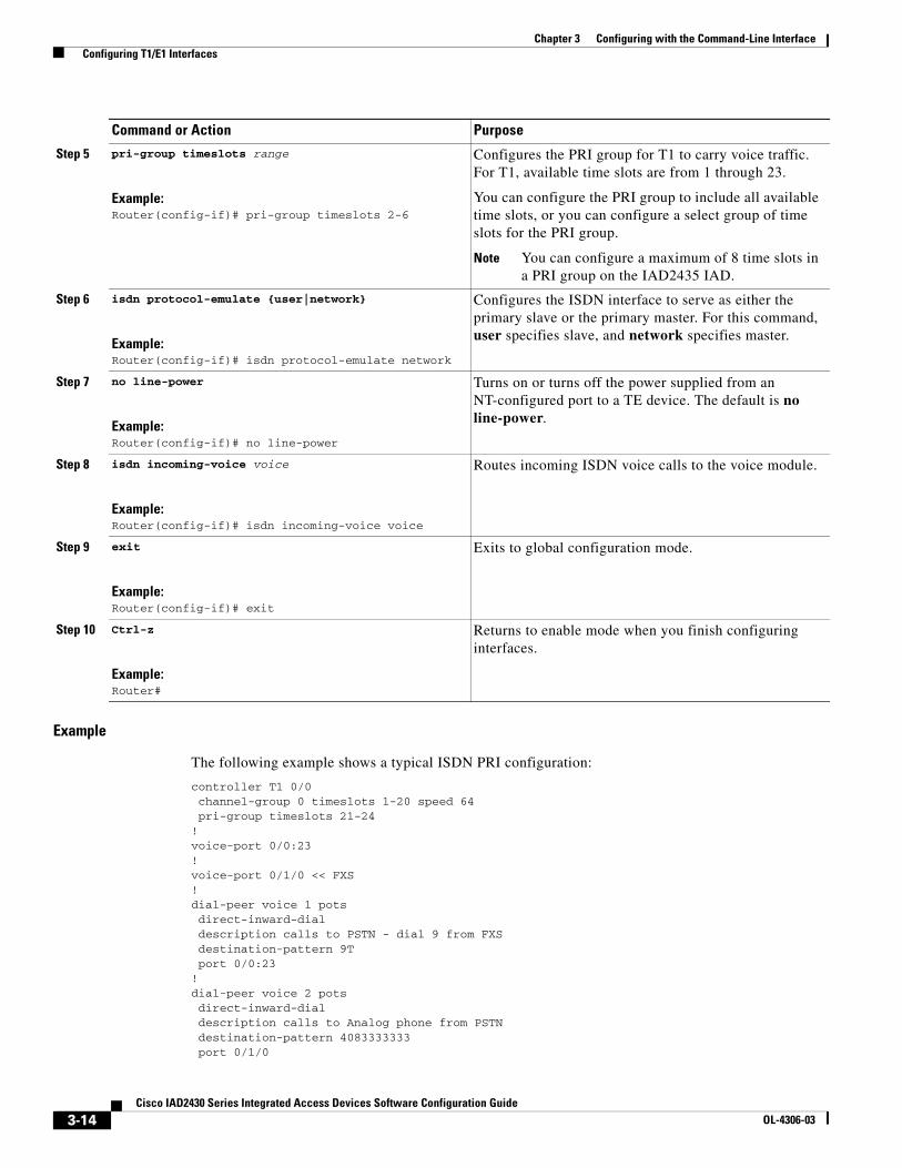
Example
The following example shows a typical ISDN PRI configuration:
controller T1 0/0 channel-group 0 timeslots 1-20 speed 64 pri-group timeslots 21-24!voice-port 0/0:23!voice-port 0/1/0 << FXS!dial-peer voice 1 pots direct-inward-dial description calls to PSTN - dial 9 from FXS destination-pattern 9T port 0/0:23!dial-peer voice 2 pots direct-inward-dial description calls to Analog phone from PSTN destination-pattern 4083333333 port 0/1/0
Step 5 pri-group timeslots range
Example:Router(config-if)# pri-group timeslots 2-6
Configures the PRI group for T1 to carry voice traffic. For T1, available time slots are from 1 through 23.
You can configure the PRI group to include all available time slots, or you can configure a select group of time slots for the PRI group.
Note You can configure a maximum of 8 time slots in a PRI group on the IAD2435 IAD.
Step 6 isdn protocol-emulate {user|network}
Example:Router(config-if)# isdn protocol-emulate network
Configures the ISDN interface to serve as either the primary slave or the primary master. For this command, user specifies slave, and network specifies master.
Step 7 no line-power
Example:Router(config-if)# no line-power
Turns on or turns off the power supplied from an NT-configured port to a TE device. The default is no line-power.
Step 8 isdn incoming-voice voice
Example:Router(config-if)# isdn incoming-voice voice
Routes incoming ISDN voice calls to the voice module.
Step 9 exit
Example:Router(config-if)# exit
Exits to global configuration mode.
Step 10 Ctrl-z
Example:Router#
Returns to enable mode when you finish configuring interfaces.
Command or Action Purpose
3-14Cisco IAD2430 Series Integrated Access Devices Software Configuration Guide
OL-4306-03
Chapter 3 Configuring with the Command-Line Interface Configuring T1/E1 Interfaces
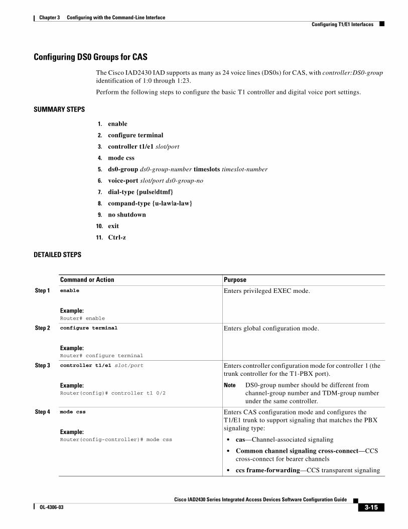
Configuring DS0 Groups for CAS
The Cisco IAD2430 IAD supports as many as 24 voice lines (DS0s) for CAS, with controller:DS0-group identification of 1:0 through 1:23.
Perform the following steps to configure the basic T1 controller and digital voice port settings.
SUMMARY STEPS
1. enable
2. configure terminal
3. controller t1/e1 slot/port
4. mode css
5. ds0-group ds0-group-number timeslots timeslot-number
6. voice-port slot/port ds0-group-no
7. dial-type {pulse|dtmf}
8. compand-type {u-law|a-law}
9. no shutdown
10. exit
11. Ctrl-z
DETAILED STEPS
Command or Action Purpose
Step 1 enable
Example:Router# enable
Enters privileged EXEC mode.
Step 2 configure terminal
Example:Router# configure terminal
Enters global configuration mode.
Step 3 controller t1/e1 slot/port
Example:Router(config)# controller t1 0/2
Enters controller configuration mode for controller 1 (the trunk controller for the T1-PBX port).
Note DS0-group number should be different from channel-group number and TDM-group number under the same controller.
Step 4 mode css
Example:Router(config-controller)# mode css
Enters CAS configuration mode and configures the T1/E1 trunk to support signaling that matches the PBX signaling type:
• cas—Channel-associated signaling
• Common channel signaling cross-connect—CCS cross-connect for bearer channels
• ccs frame-forwarding—CCS transparent signaling
3-15Cisco IAD2430 Series Integrated Access Devices Software Configuration Guide
OL-4306-03
Chapter 3 Configuring with the Command-Line Interface Configuring T1/E1 Interfaces
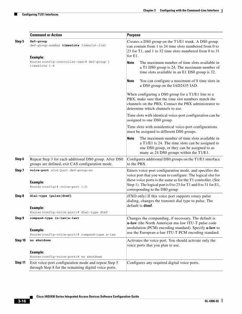
Step 5 ds0-group ds0-group-number timeslots timeslot-list
Example:Router(config-controller-cas)# ds0-group 1 timeslots 1-4
Creates a DS0 group on the T1/E1 trunk. A DS0 group can contain from 1 to 24 time slots numbered from 0 to 23 for T1, and 1 to 32 time slots numbered from 0 to 31 for E1.
Note The maximum number of time slots available in a T1 DS0 group is 24. The maximum number of time slots available in an E1 DS0 group is 32.
Note You can configure a maximum of 8 time slots in a DS0 group on the IAD2435 IAD.
When configuring a DS0 group for a T1/E1 line to a PBX, make sure that the time slot numbers match the channels on the PBX. Contact the PBX administrator to determine which channels to use.
Time slots with identical voice-port configuration can be assigned to one DS0 group.
Time slots with nonidentical voice-port configurations must be assigned to different DS0 groups.
Note The maximum number of time slots available in a T1/E1 is 24. The time slots can be assigned to one DS0 group, or they can be assigned to as many as 24 DS0 groups within the T1/E1.
Step 6 Repeat Step 3 for each additional DS0 group. After DS0 groups are defined, exit CAS configuration mode.
Configures additional DS0 groups on the T1/E1 interface to the PBX.
Step 7 voice-port slot/port ds0-group-no
Example:Router(config)# voice-port 1:D
Enters voice-port configuration mode, and specifies the voice port that you want to configure. The logical slot for these voice ports is the same as for the T1 controller. (See Step 1). The logical port is 0 to 23 for T1 and 0 to 31 for E1, corresponding to the DS0 group.
Step 8 dial-type {pulse|dtmf}
Example:Router(config-voice-port)# dial-type dtmf
(FXO only) If this voice port supports rotary pulse dialing, changes the transmit dial type to pulse. The default is dtmf.
Step 9 compand-type {u-law|a-law}
Example:Router(config-voice-port)# compand-type a-law
Changes the companding, if necessary. The default is u-law (the North American mu-law ITU-T pulse code modulation (PCM) encoding standard). Specify a-law to use the European a-law ITU-T PCM encoding standard.
Step 10 no shutdown
Example:Router(config-voice-port)# no shutdown
Activates the voice port. You should activate only the voice ports that you plan to use.
Step 11 Exit voice-port configuration mode and repeat Step 5 through Step 8 for the remaining digital voice ports.
Configures any required digital voice ports.
Command or Action Purpose
3-16Cisco IAD2430 Series Integrated Access Devices Software Configuration Guide
OL-4306-03
Chapter 3 Configuring with the Command-Line Interface Configuring T1/E1 Interfaces
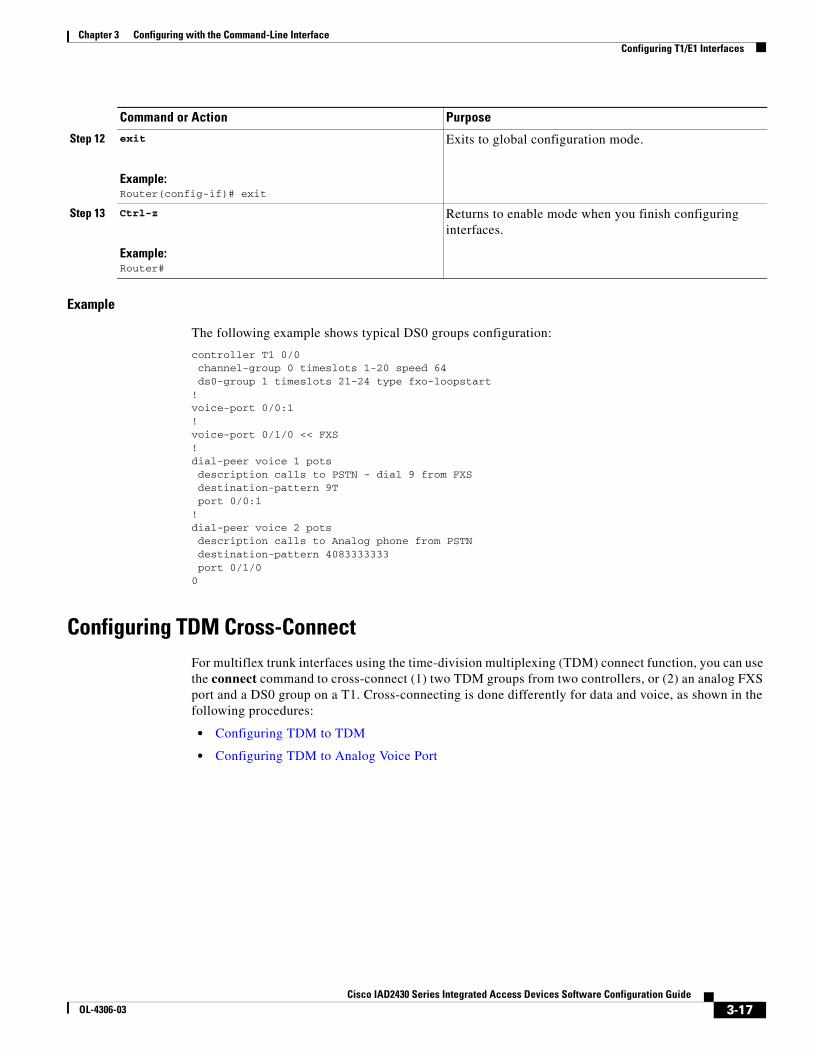
Example
The following example shows typical DS0 groups configuration:
controller T1 0/0 channel-group 0 timeslots 1-20 speed 64 ds0-group 1 timeslots 21-24 type fxo-loopstart!voice-port 0/0:1!voice-port 0/1/0 << FXS!dial-peer voice 1 pots description calls to PSTN - dial 9 from FXS destination-pattern 9T port 0/0:1!dial-peer voice 2 pots description calls to Analog phone from PSTN destination-pattern 4083333333 port 0/1/00
Configuring TDM Cross-ConnectFor multiflex trunk interfaces using the time-division multiplexing (TDM) connect function, you can use the connect command to cross-connect (1) two TDM groups from two controllers, or (2) an analog FXS port and a DS0 group on a T1. Cross-connecting is done differently for data and voice, as shown in the following procedures:
• Configuring TDM to TDM
• Configuring TDM to Analog Voice Port
Step 12 exit
Example:Router(config-if)# exit
Exits to global configuration mode.
Step 13 Ctrl-z
Example:Router#
Returns to enable mode when you finish configuring interfaces.
Command or Action Purpose
3-17Cisco IAD2430 Series Integrated Access Devices Software Configuration Guide
OL-4306-03
Chapter 3 Configuring with the Command-Line Interface Configuring T1/E1 Interfaces
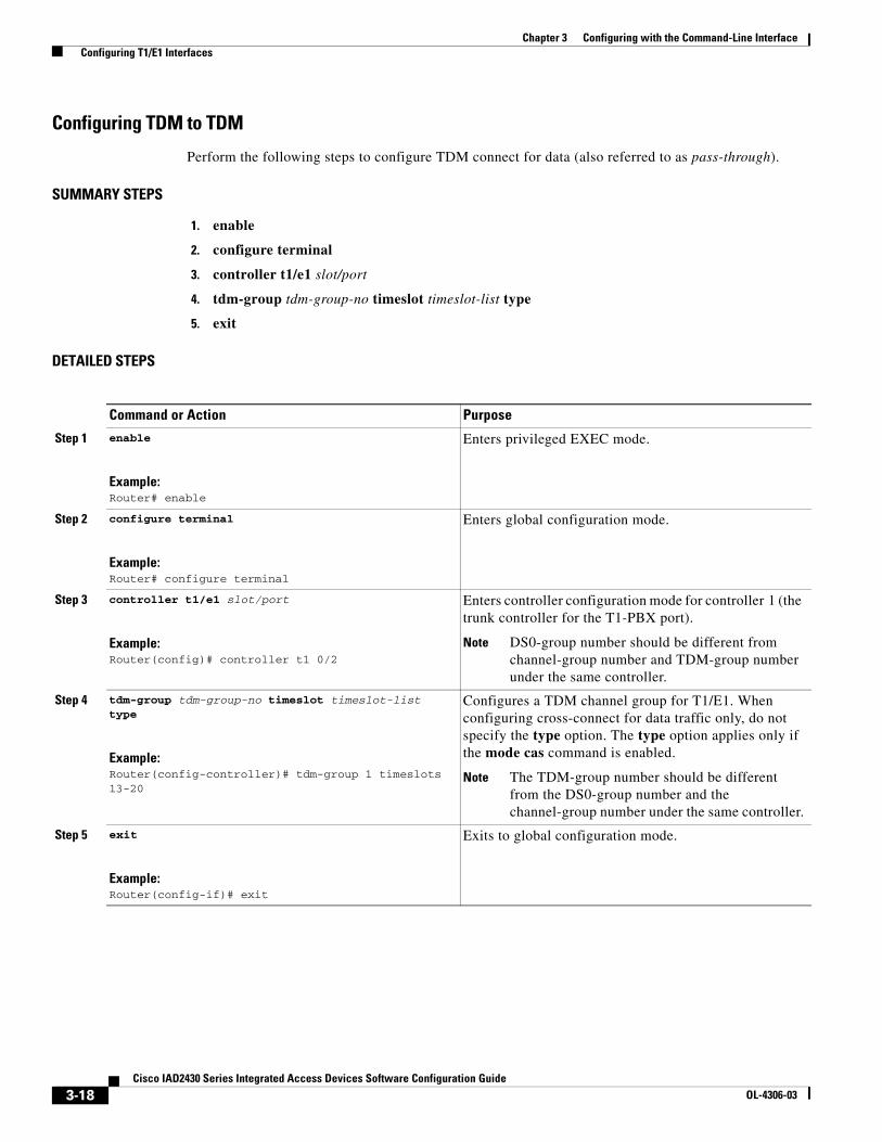
Configuring TDM to TDM
Perform the following steps to configure TDM connect for data (also referred to as pass-through).
SUMMARY STEPS
1. enable
2. configure terminal
3. controller t1/e1 slot/port
4. tdm-group tdm-group-no timeslot timeslot-list type
5. exit
DETAILED STEPS
Command or Action Purpose
Step 1 enable
Example:Router# enable
Enters privileged EXEC mode.
Step 2 configure terminal
Example:Router# configure terminal
Enters global configuration mode.
Step 3 controller t1/e1 slot/port
Example:Router(config)# controller t1 0/2
Enters controller configuration mode for controller 1 (the trunk controller for the T1-PBX port).
Note DS0-group number should be different from channel-group number and TDM-group number under the same controller.
Step 4 tdm-group tdm-group-no timeslot timeslot-list type
Example:Router(config-controller)# tdm-group 1 timeslots 13-20
Configures a TDM channel group for T1/E1. When configuring cross-connect for data traffic only, do not specify the type option. The type option applies only if the mode cas command is enabled.
Note The TDM-group number should be different from the DS0-group number and the channel-group number under the same controller.
Step 5 exit
Example:Router(config-if)# exit
Exits to global configuration mode.
3-18Cisco IAD2430 Series Integrated Access Devices Software Configuration Guide
OL-4306-03
Chapter 3 Configuring with the Command-Line Interface Configuring T1/E1 Interfaces
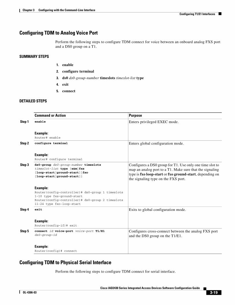
Configuring TDM to Analog Voice Port
Perform the following steps to configure TDM connect for voice between an onboard analog FXS port and a DS0 group on a T1.
SUMMARY STEPS
1. enable
2. configure terminal
3. ds0 ds0-group-number timeslots timeslot-list type
4. exit
5. connect
DETAILED STEPS
Configuring TDM to Physical Serial Interface
Perform the following steps to configure TDM connect for serial interface.
Command or Action Purpose
Step 1 enable
Example:Router# enable
Enters privileged EXEC mode.
Step 2 configure terminal
Example:Router# configure terminal
Enters global configuration mode.
Step 3 ds0-group ds0-group-number timeslots timeslot-list type {e&m|fxs [loop-start|ground-start]|fxo [loop-start|ground-start]}
Example:Router(config-controller)# ds0-group 1 timeslots 1-10 type fxs-ground-startRouter(config-controller)# ds0-group 2 timeslots 11-24 type fxo-loop-start
Configures a DS0 group for T1. Use only one time slot to map an analog port to a T1. Make sure that the signaling type is fxo loop-start or fxo ground-start, depending on the signaling type on the FXS port.
Step 4 exit
Example:Router(config-if)# exit
Exits to global configuration mode.
Step 5 connect id voice-port voice-port T1/E1 ds0-group-id
Example:Router(config)# connect
Configures cross-connect between the analog FXS port and the DS0 group on the T1/E1.
3-19Cisco IAD2430 Series Integrated Access Devices Software Configuration Guide
OL-4306-03

Chapter 3 Configuring with the Command-Line Interface Configuring T1/E1 Interfaces
Note The serial interface must be a DTE device.
SUMMARY STEPS
1. enable
2. configure terminal
3. tdm-group tdm-group-no timeslot timeslot-list
4. exit
5. interface type number
6. no keepalive
7. exit
8. connect
DETAILED STEPS
Command or Action Purpose
Step 1 enable
Example:Router# enable
Enters privileged EXEC mode.
Step 2 configure terminal
Example:Router# configure terminal
Enters global configuration mode.
Step 3 tdm-group tdm-group-no timeslot timeslot-list
Example:Router(config-controller)# tdm-group 1 timeslot 13-20
Configures a list of time slots for creating clear channel groups (pass-through) for time-division multiplexing (TDM) cross-connect.
When configuring cross-connect for data traffic only, do not specify the type option.
Step 4 exit
Example:Router(config-controller)# exit
Exits to global controller mode.
Step 5 interface type number
Example:Router(config-controller)# interface serial 1/0:0
Configures the serial interface.
Step 6 no keepalive
Example:Router(config-if)# no keepalive
Sets the no keepalive function.
3-20Cisco IAD2430 Series Integrated Access Devices Software Configuration Guide
OL-4306-03
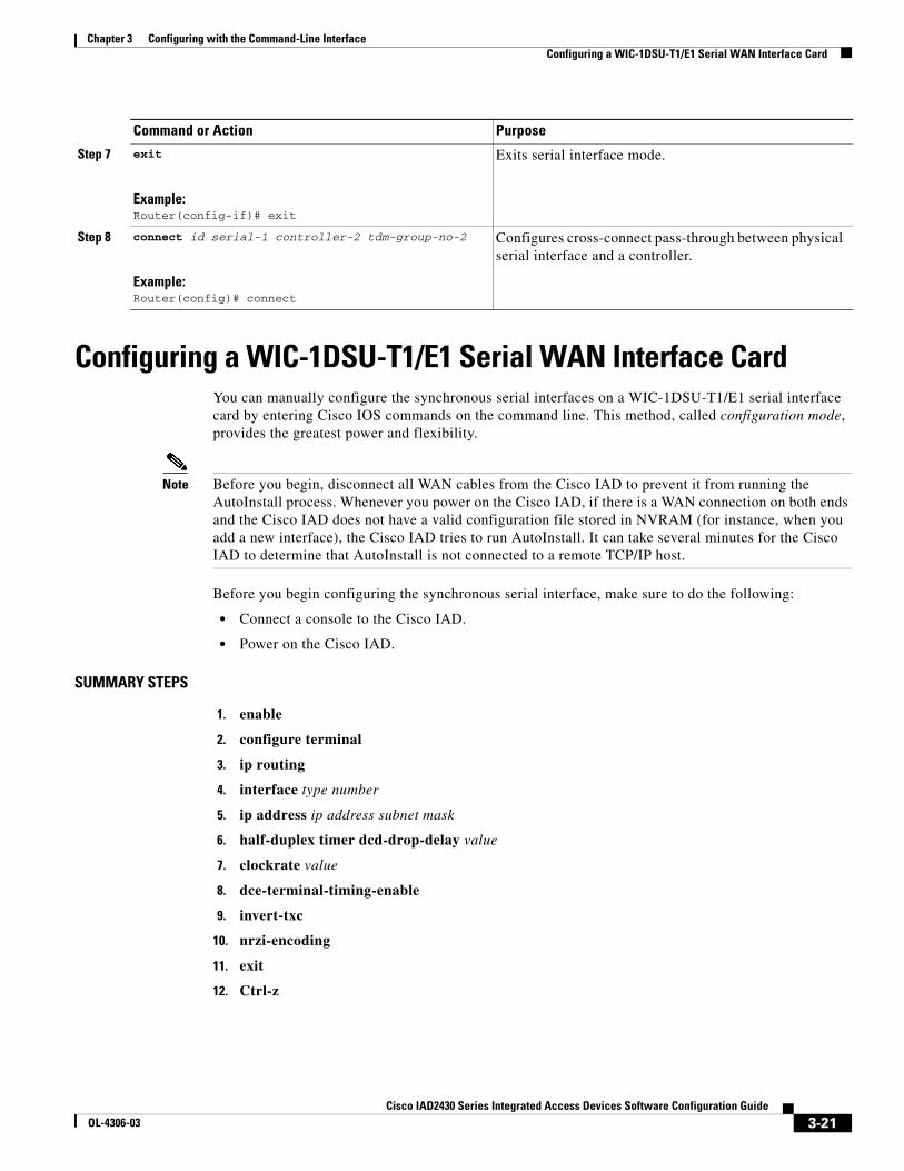
Chapter 3 Configuring with the Command-Line Interface Configuring a WIC-1DSU-T1/E1 Serial WAN Interface Card
Configuring a WIC-1DSU-T1/E1 Serial WAN Interface CardYou can manually configure the synchronous serial interfaces on a WIC-1DSU-T1/E1 serial interface card by entering Cisco IOS commands on the command line. This method, called configuration mode, provides the greatest power and flexibility.
Note Before you begin, disconnect all WAN cables from the Cisco IAD to prevent it from running the AutoInstall process. Whenever you power on the Cisco IAD, if there is a WAN connection on both ends and the Cisco IAD does not have a valid configuration file stored in NVRAM (for instance, when you add a new interface), the Cisco IAD tries to run AutoInstall. It can take several minutes for the Cisco IAD to determine that AutoInstall is not connected to a remote TCP/IP host.
Before you begin configuring the synchronous serial interface, make sure to do the following:
• Connect a console to the Cisco IAD.
• Power on the Cisco IAD.
SUMMARY STEPS
1. enable
2. configure terminal
3. ip routing
4. interface type number
5. ip address ip address subnet mask
6. half-duplex timer dcd-drop-delay value
7. clockrate value
8. dce-terminal-timing-enable
9. invert-txc
10. nrzi-encoding
11. exit
12. Ctrl-z
Step 7 exit
Example:Router(config-if)# exit
Exits serial interface mode.
Step 8 connect id serial-1 controller-2 tdm-group-no-2
Example:Router(config)# connect
Configures cross-connect pass-through between physical serial interface and a controller.
Command or Action Purpose
3-21Cisco IAD2430 Series Integrated Access Devices Software Configuration Guide
OL-4306-03
Chapter 3 Configuring with the Command-Line Interface Configuring a WIC-1DSU-T1/E1 Serial WAN Interface Card
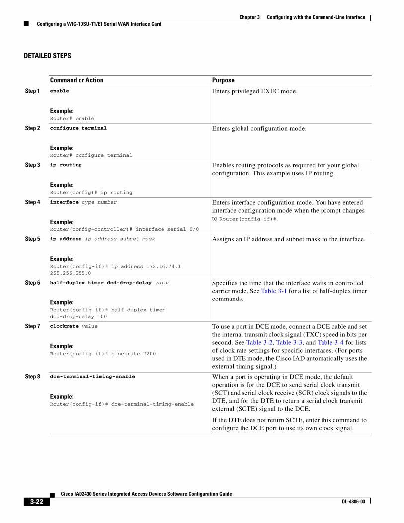
DETAILED STEPS
Command or Action Purpose
Step 1 enable
Example:Router# enable
Enters privileged EXEC mode.
Step 2 configure terminal
Example:Router# configure terminal
Enters global configuration mode.
Step 3 ip routing
Example:Router(config)# ip routing
Enables routing protocols as required for your global configuration. This example uses IP routing.
Step 4 interface type number
Example:Router(config-controller)# interface serial 0/0
Enters interface configuration mode. You have entered interface configuration mode when the prompt changes to Router(config-if)#.
Step 5 ip address ip address subnet mask
Example:Router(config-if)# ip address 172.16.74.1 255.255.255.0
Assigns an IP address and subnet mask to the interface.
Step 6 half-duplex timer dcd-drop-delay value
Example:Router(config-if)# half-duplex timer dcd-drop-delay 100
Specifies the time that the interface waits in controlled carrier mode. See Table 3-1 for a list of half-duplex timer commands.
Step 7 clockrate value
Example:Router(config-if)# clockrate 7200
To use a port in DCE mode, connect a DCE cable and set the internal transmit clock signal (TXC) speed in bits per second. See Table 3-2, Table 3-3, and Table 3-4 for lists of clock rate settings for specific interfaces. (For ports used in DTE mode, the Cisco IAD automatically uses the external timing signal.)
Step 8 dce-terminal-timing-enable
Example:Router(config-if)# dce-terminal-timing-enable
When a port is operating in DCE mode, the default operation is for the DCE to send serial clock transmit (SCT) and serial clock receive (SCR) clock signals to the DTE, and for the DTE to return a serial clock transmit external (SCTE) signal to the DCE.
If the DTE does not return SCTE, enter this command to configure the DCE port to use its own clock signal.
3-22Cisco IAD2430 Series Integrated Access Devices Software Configuration Guide
OL-4306-03
Chapter 3 Configuring with the Command-Line Interface Configuring a WIC-1DSU-T1/E1 Serial WAN Interface Card
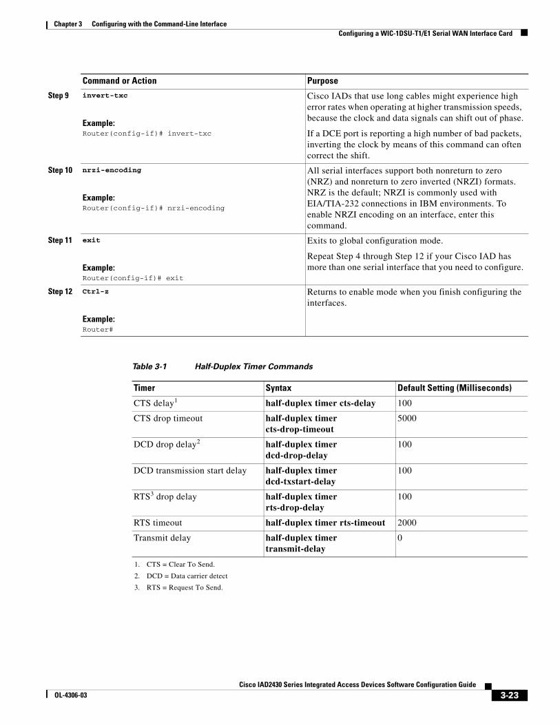
Step 9 invert-txc
Example:Router(config-if)# invert-txc
Cisco IADs that use long cables might experience high error rates when operating at higher transmission speeds, because the clock and data signals can shift out of phase.
If a DCE port is reporting a high number of bad packets, inverting the clock by means of this command can often correct the shift.
Step 10 nrzi-encoding
Example:Router(config-if)# nrzi-encoding
All serial interfaces support both nonreturn to zero (NRZ) and nonreturn to zero inverted (NRZI) formats. NRZ is the default; NRZI is commonly used with EIA/TIA-232 connections in IBM environments. To enable NRZI encoding on an interface, enter this command.
Step 11 exit
Example:Router(config-if)# exit
Exits to global configuration mode.
Repeat Step 4 through Step 12 if your Cisco IAD has more than one serial interface that you need to configure.
Step 12 Ctrl-z
Example:Router#
Returns to enable mode when you finish configuring the interfaces.
Table 3-1 Half-Duplex Timer Commands
Timer Syntax Default Setting (Milliseconds)
CTS delay1
1. CTS = Clear To Send.
half-duplex timer cts-delay 100
CTS drop timeout half-duplex timer cts-drop-timeout
5000
DCD drop delay2
2. DCD = Data carrier detect
half-duplex timer dcd-drop-delay
100
DCD transmission start delay half-duplex timer dcd-txstart-delay
100
RTS3 drop delay
3. RTS = Request To Send.
half-duplex timer rts-drop-delay
100
RTS timeout half-duplex timer rts-timeout 2000
Transmit delay half-duplex timer transmit-delay
0
Command or Action Purpose
3-23Cisco IAD2430 Series Integrated Access Devices Software Configuration Guide
OL-4306-03
Chapter 3 Configuring with the Command-Line Interface Configuring a WIC-1T or WIC-2T Serial WAN Interface Card
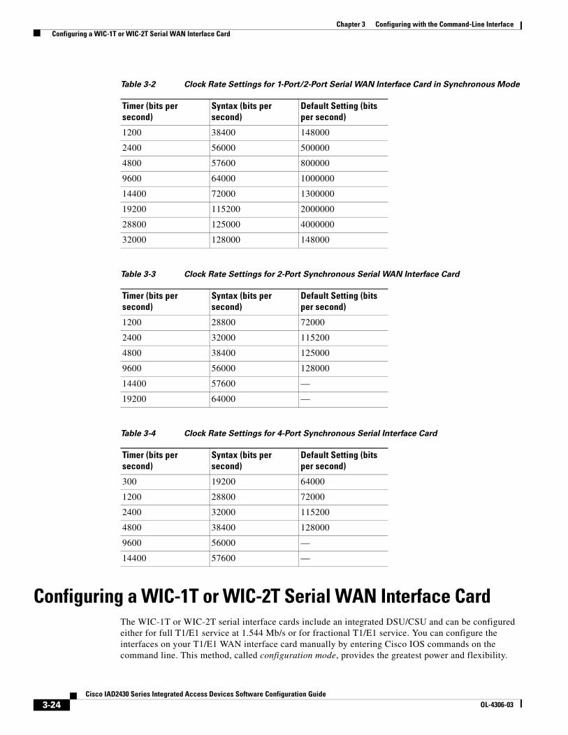
Configuring a WIC-1T or WIC-2T Serial WAN Interface CardThe WIC-1T or WIC-2T serial interface cards include an integrated DSU/CSU and can be configured either for full T1/E1 service at 1.544 Mb/s or for fractional T1/E1 service. You can configure the interfaces on your T1/E1 WAN interface card manually by entering Cisco IOS commands on the command line. This method, called configuration mode, provides the greatest power and flexibility.
Table 3-2 Clock Rate Settings for 1-Port/2-Port Serial WAN Interface Card in Synchronous Mode
Timer (bits per second)
Syntax (bits per second)
Default Setting (bits per second)
1200 38400 148000
2400 56000 500000
4800 57600 800000
9600 64000 1000000
14400 72000 1300000
19200 115200 2000000
28800 125000 4000000
32000 128000 148000
Table 3-3 Clock Rate Settings for 2-Port Synchronous Serial WAN Interface Card
Timer (bits per second)
Syntax (bits per second)
Default Setting (bits per second)
1200 28800 72000
2400 32000 115200
4800 38400 125000
9600 56000 128000
14400 57600 —
19200 64000 —
Table 3-4 Clock Rate Settings for 4-Port Synchronous Serial Interface Card
Timer (bits per second)
Syntax (bits per second)
Default Setting (bits per second)
300 19200 64000
1200 28800 72000
2400 32000 115200
4800 38400 128000
9600 56000 —
14400 57600 —
3-24Cisco IAD2430 Series Integrated Access Devices Software Configuration Guide
OL-4306-03
Chapter 3 Configuring with the Command-Line Interface Configuring a VIC2-2FXO or VIC2-4FXO Voice Interface Card
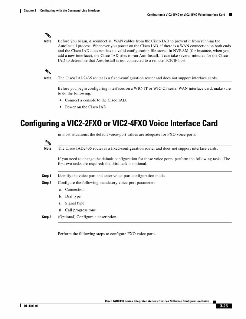
Note Before you begin, disconnect all WAN cables from the Cisco IAD to prevent it from running the AutoInstall process. Whenever you power on the Cisco IAD, if there is a WAN connection on both ends and the Cisco IAD does not have a valid configuration file stored in NVRAM (for instance, when you add a new interface), the Cisco IAD tries to run AutoInstall. It can take several minutes for the Cisco IAD to determine that AutoInstall is not connected to a remote TCP/IP host.
Note The Cisco IAD2435 router is a fixed-configuration router and does not support interface cards.
Before you begin configuring interfaces on a WIC-1T or WIC-2T serial WAN interface card, make sure to do the following:
• Connect a console to the Cisco IAD.
• Power on the Cisco IAD.
Configuring a VIC2-2FXO or VIC2-4FXO Voice Interface Cardin most situations, the default voice-port values are adequate for FXO voice ports.
Note The Cisco IAD2435 router is a fixed-configuration router and does not support interface cards.
If you need to change the default configuration for these voice ports, perform the following tasks. The first two tasks are required; the third task is optional.
Step 1 Identify the voice port and enter voice-port configuration mode.
Step 2 Configure the following mandatory voice-port parameters:
a. Connection
b. Dial type
c. Signal type
d. Call progress tone
Step 3 (Optional) Configure a description.
Perform the following steps to configure FXO voice ports.
3-25Cisco IAD2430 Series Integrated Access Devices Software Configuration Guide
OL-4306-03
Chapter 3 Configuring with the Command-Line Interface Configuring a VIC2-2FXO or VIC2-4FXO Voice Interface Card
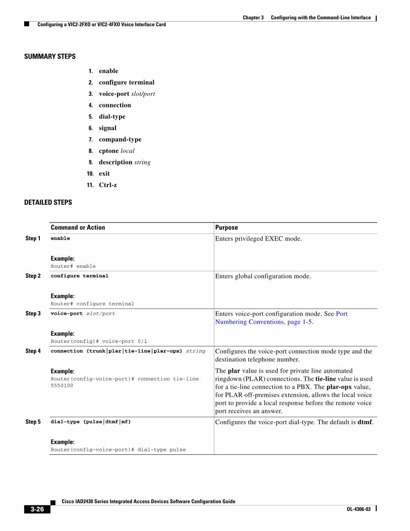
SUMMARY STEPS
1. enable
2. configure terminal
3. voice-port slot/port
4. connection
5. dial-type
6. signal
7. compand-type
8. cptone local
9. description string
10. exit
11. Ctrl-z
DETAILED STEPS
Command or Action Purpose
Step 1 enable
Example:Router# enable
Enters privileged EXEC mode.
Step 2 configure terminal
Example:Router# configure terminal
Enters global configuration mode.
Step 3 voice-port slot/port
Example:Router(config)# voice-port 0/1
Enters voice-port configuration mode. See Port Numbering Conventions, page 1-5.
Step 4 connection {trunk|plar|tie-line|plar-opx} string
Example:Router(config-voice-port)# connection tie-line 5550100
Configures the voice-port connection mode type and the destination telephone number.
The plar value is used for private line automated ringdown (PLAR) connections. The tie-line value is used for a tie-line connection to a PBX. The plar-opx value, for PLAR off-premises extension, allows the local voice port to provide a local response before the remote voice port receives an answer.
Step 5 dial-type {pulse|dtmf|mf}
Example:Router(config-voice-port)# dial-type pulse
Configures the voice-port dial-type. The default is dtmf.
3-26Cisco IAD2430 Series Integrated Access Devices Software Configuration Guide
OL-4306-03
Chapter 3 Configuring with the Command-Line Interface Configuring a VIC2-2FXS or VIC2-4FXS Voice Interface Card
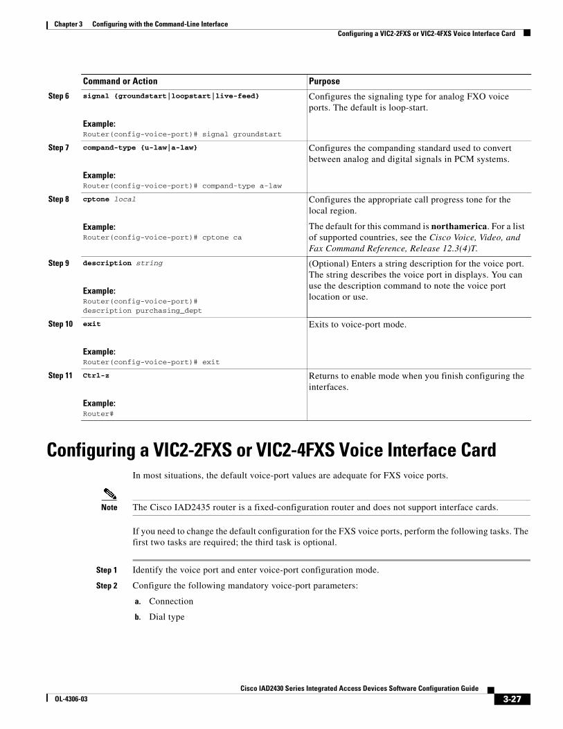
Configuring a VIC2-2FXS or VIC2-4FXS Voice Interface CardIn most situations, the default voice-port values are adequate for FXS voice ports.
Note The Cisco IAD2435 router is a fixed-configuration router and does not support interface cards.
If you need to change the default configuration for the FXS voice ports, perform the following tasks. The first two tasks are required; the third task is optional.
Step 1 Identify the voice port and enter voice-port configuration mode.
Step 2 Configure the following mandatory voice-port parameters:
a. Connection
b. Dial type
Step 6 signal {groundstart|loopstart|live-feed}
Example:Router(config-voice-port)# signal groundstart
Configures the signaling type for analog FXO voice ports. The default is loop-start.
Step 7 compand-type {u-law|a-law}
Example:Router(config-voice-port)# compand-type a-law
Configures the companding standard used to convert between analog and digital signals in PCM systems.
Step 8 cptone local
Example:Router(config-voice-port)# cptone ca
Configures the appropriate call progress tone for the local region.
The default for this command is northamerica. For a list of supported countries, see the Cisco Voice, Video, and Fax Command Reference, Release 12.3(4)T.
Step 9 description string
Example:Router(config-voice-port)# description purchasing_dept
(Optional) Enters a string description for the voice port. The string describes the voice port in displays. You can use the description command to note the voice port location or use.
Step 10 exit
Example:Router(config-voice-port)# exit
Exits to voice-port mode.
Step 11 Ctrl-z
Example:Router#
Returns to enable mode when you finish configuring the interfaces.
Command or Action Purpose
3-27Cisco IAD2430 Series Integrated Access Devices Software Configuration Guide
OL-4306-03
Chapter 3 Configuring with the Command-Line Interface Configuring a VIC2-2FXS or VIC2-4FXS Voice Interface Card
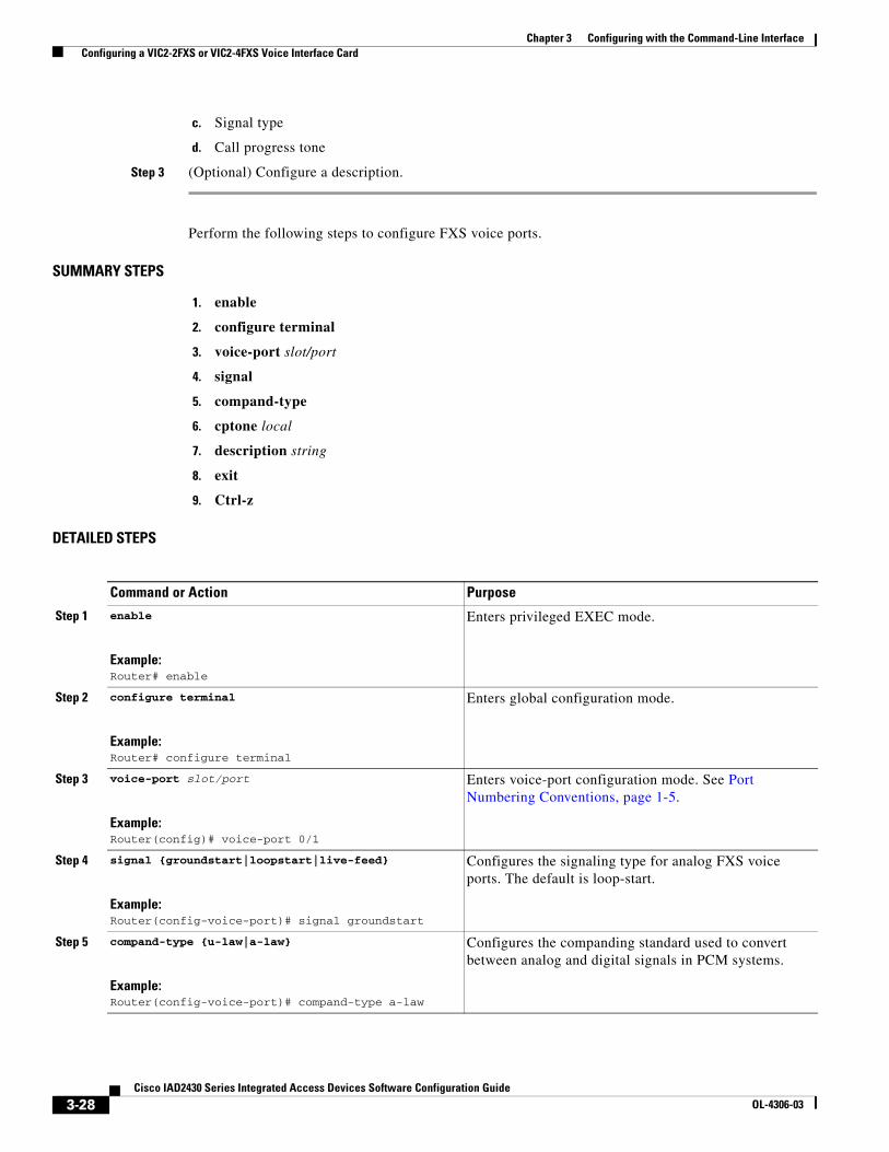
c. Signal type
d. Call progress tone
Step 3 (Optional) Configure a description.
Perform the following steps to configure FXS voice ports.
SUMMARY STEPS
1. enable
2. configure terminal
3. voice-port slot/port
4. signal
5. compand-type
6. cptone local
7. description string
8. exit
9. Ctrl-z
DETAILED STEPS
Command or Action Purpose
Step 1 enable
Example:Router# enable
Enters privileged EXEC mode.
Step 2 configure terminal
Example:Router# configure terminal
Enters global configuration mode.
Step 3 voice-port slot/port
Example:Router(config)# voice-port 0/1
Enters voice-port configuration mode. See Port Numbering Conventions, page 1-5.
Step 4 signal {groundstart|loopstart|live-feed}
Example:Router(config-voice-port)# signal groundstart
Configures the signaling type for analog FXS voice ports. The default is loop-start.
Step 5 compand-type {u-law|a-law}
Example:Router(config-voice-port)# compand-type a-law
Configures the companding standard used to convert between analog and digital signals in PCM systems.
3-28Cisco IAD2430 Series Integrated Access Devices Software Configuration Guide
OL-4306-03
Chapter 3 Configuring with the Command-Line Interface Configuring ATM T1-WAN Ports
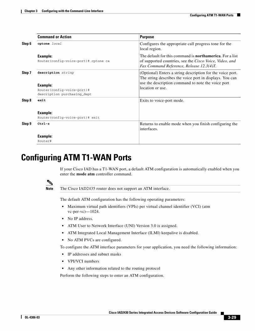
Configuring ATM T1-WAN PortsIf your Cisco IAD has a T1-WAN port, a default ATM configuration is automatically enabled when you enter the mode atm controller command.
Note The Cisco IAD2435 router does not support an ATM interface.
The default ATM configuration has the following operating parameters:
• Maximum virtual path identifiers (VPIs) per virtual channel identifier (VCI) (atm vc-per-vc)—1024.
• No IP address.
• ATM User to Network Interface (UNI) Version 3.0 is assigned.
• ATM Integrated Local Management Interface (ILMI) keepalive is disabled.
• No ATM PVCs are configured.
To configure the ATM interface parameters for your application, you need the following information:
• IP addresses and subnet masks
• VPI/VCI numbers
• Any other information related to the routing protocol
Perform the following steps to enter an ATM configuration.
Step 6 cptone local
Example:Router(config-voice-port)# cptone ca
Configures the appropriate call progress tone for the local region.
The default for this command is northamerica. For a list of supported countries, see the Cisco Voice, Video, and Fax Command Reference, Release 12.3(4)T.
Step 7 description string
Example:Router(config-voice-port)# description purchasing_dept
(Optional) Enters a string description for the voice port. The string describes the voice port in displays. You can use the description command to note the voice port location or use.
Step 8 exit
Example:Router(config-voice-port)# exit
Exits to voice-port mode.
Step 9 Ctrl-z
Example:Router#
Returns to enable mode when you finish configuring the interfaces.
Command or Action Purpose
3-29Cisco IAD2430 Series Integrated Access Devices Software Configuration Guide
OL-4306-03
Chapter 3 Configuring with the Command-Line Interface Configuring ATM T1-WAN Ports
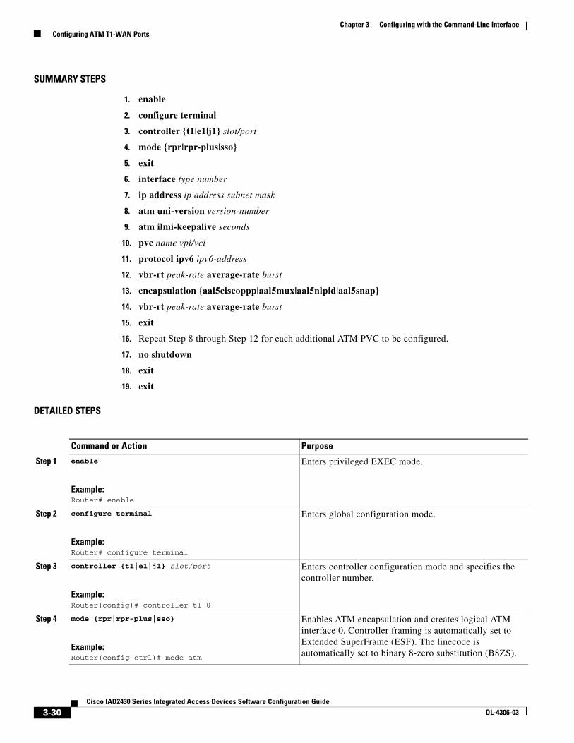
SUMMARY STEPS
1. enable
2. configure terminal
3. controller {t1|e1|j1} slot/port
4. mode {rpr|rpr-plus|sso}
5. exit
6. interface type number
7. ip address ip address subnet mask
8. atm uni-version version-number
9. atm ilmi-keepalive seconds
10. pvc name vpi/vci
11. protocol ipv6 ipv6-address
12. vbr-rt peak-rate average-rate burst
13. encapsulation {aal5ciscoppp|aal5mux|aal5nlpid|aal5snap}
14. vbr-rt peak-rate average-rate burst
15. exit
16. Repeat Step 8 through Step 12 for each additional ATM PVC to be configured.
17. no shutdown
18. exit
19. exit
DETAILED STEPS
Command or Action Purpose
Step 1 enable
Example:Router# enable
Enters privileged EXEC mode.
Step 2 configure terminal
Example:Router# configure terminal
Enters global configuration mode.
Step 3 controller {t1|e1|j1} slot/port
Example:Router(config)# controller t1 0
Enters controller configuration mode and specifies the controller number.
Step 4 mode {rpr|rpr-plus|sso}
Example:Router(config-ctrl)# mode atm
Enables ATM encapsulation and creates logical ATM interface 0. Controller framing is automatically set to Extended SuperFrame (ESF). The linecode is automatically set to binary 8-zero substitution (B8ZS).
3-30Cisco IAD2430 Series Integrated Access Devices Software Configuration Guide
OL-4306-03
Chapter 3 Configuring with the Command-Line Interface Configuring ATM T1-WAN Ports
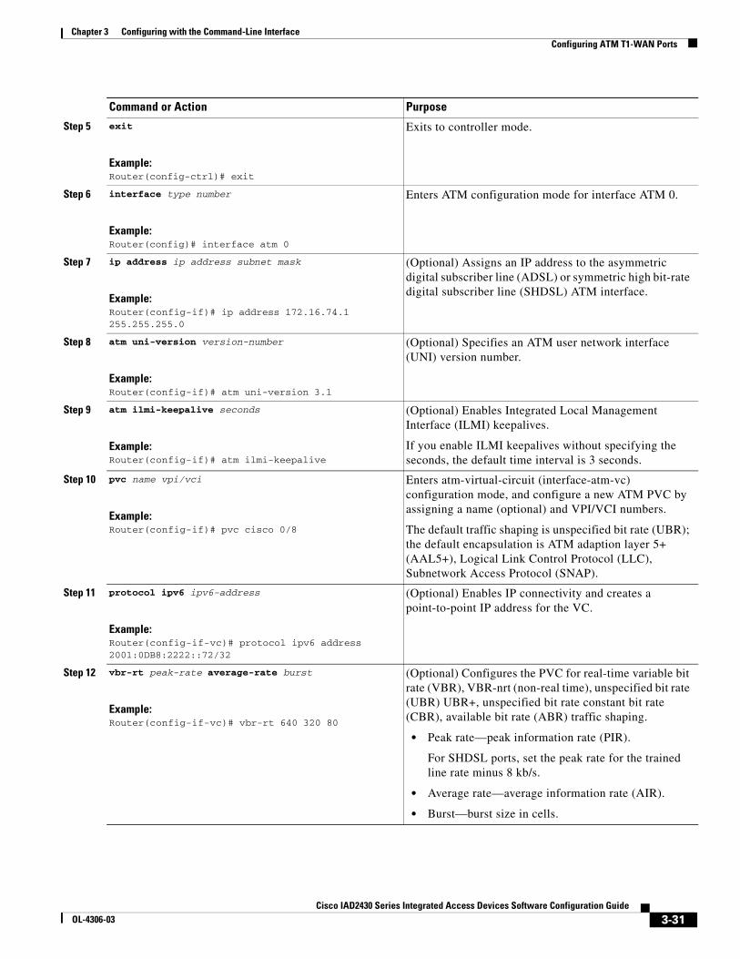
Step 5 exit
Example:Router(config-ctrl)# exit
Exits to controller mode.
Step 6 interface type number
Example:Router(config)# interface atm 0
Enters ATM configuration mode for interface ATM 0.
Step 7 ip address ip address subnet mask
Example:Router(config-if)# ip address 172.16.74.1 255.255.255.0
(Optional) Assigns an IP address to the asymmetric digital subscriber line (ADSL) or symmetric high bit-rate digital subscriber line (SHDSL) ATM interface.
Step 8 atm uni-version version-number
Example:Router(config-if)# atm uni-version 3.1
(Optional) Specifies an ATM user network interface (UNI) version number.
Step 9 atm ilmi-keepalive seconds
Example:Router(config-if)# atm ilmi-keepalive
(Optional) Enables Integrated Local Management Interface (ILMI) keepalives.
If you enable ILMI keepalives without specifying the seconds, the default time interval is 3 seconds.
Step 10 pvc name vpi/vci
Example:Router(config-if)# pvc cisco 0/8
Enters atm-virtual-circuit (interface-atm-vc) configuration mode, and configure a new ATM PVC by assigning a name (optional) and VPI/VCI numbers.
The default traffic shaping is unspecified bit rate (UBR); the default encapsulation is ATM adaption layer 5+ (AAL5+), Logical Link Control Protocol (LLC), Subnetwork Access Protocol (SNAP).
Step 11 protocol ipv6 ipv6-address
Example:Router(config-if-vc)# protocol ipv6 address 2001:0DB8:2222::72/32
(Optional) Enables IP connectivity and creates a point-to-point IP address for the VC.
Step 12 vbr-rt peak-rate average-rate burst
Example:Router(config-if-vc)# vbr-rt 640 320 80
(Optional) Configures the PVC for real-time variable bit rate (VBR), VBR-nrt (non-real time), unspecified bit rate (UBR) UBR+, unspecified bit rate constant bit rate (CBR), available bit rate (ABR) traffic shaping.
• Peak rate—peak information rate (PIR).
For SHDSL ports, set the peak rate for the trained line rate minus 8 kb/s.
• Average rate—average information rate (AIR).
• Burst—burst size in cells.
Command or Action Purpose
3-31Cisco IAD2430 Series Integrated Access Devices Software Configuration Guide
OL-4306-03
Chapter 3 Configuring with the Command-Line Interface Configuring ATM T1-WAN Ports
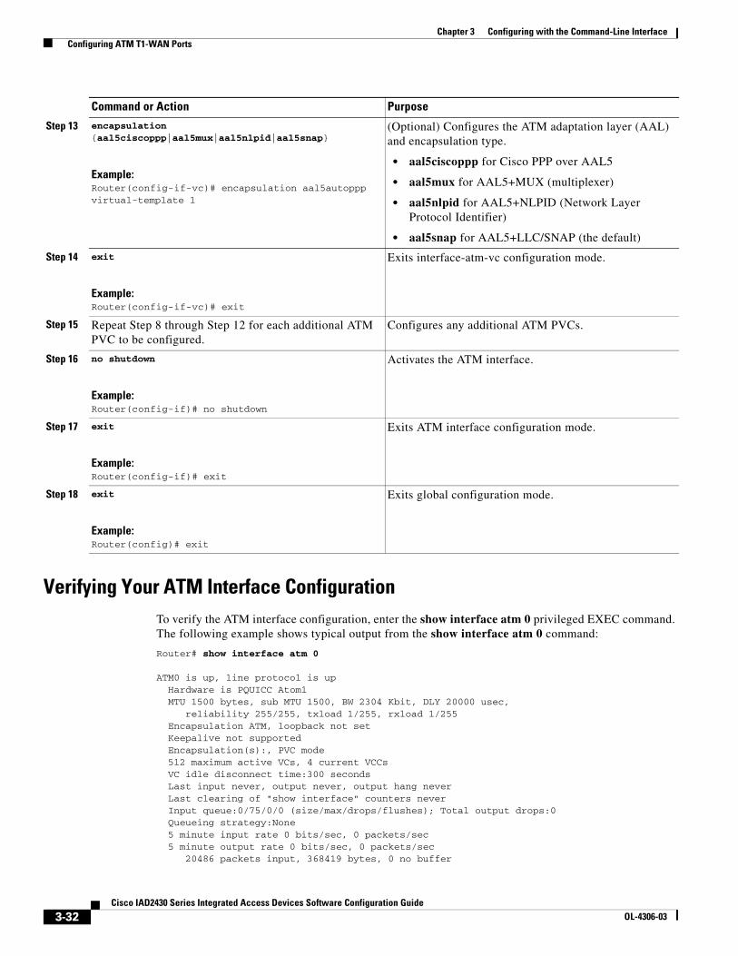
Verifying Your ATM Interface ConfigurationTo verify the ATM interface configuration, enter the show interface atm 0 privileged EXEC command. The following example shows typical output from the show interface atm 0 command:
Router# show interface atm 0
ATM0 is up, line protocol is up Hardware is PQUICC Atom1 MTU 1500 bytes, sub MTU 1500, BW 2304 Kbit, DLY 20000 usec, reliability 255/255, txload 1/255, rxload 1/255 Encapsulation ATM, loopback not set Keepalive not supported Encapsulation(s):, PVC mode 512 maximum active VCs, 4 current VCCs VC idle disconnect time:300 seconds Last input never, output never, output hang never Last clearing of "show interface" counters never Input queue:0/75/0/0 (size/max/drops/flushes); Total output drops:0 Queueing strategy:None 5 minute input rate 0 bits/sec, 0 packets/sec 5 minute output rate 0 bits/sec, 0 packets/sec 20486 packets input, 368419 bytes, 0 no buffer
Step 13 encapsulation {aal5ciscoppp|aal5mux|aal5nlpid|aal5snap}
Example:Router(config-if-vc)# encapsulation aal5autoppp virtual-template 1
(Optional) Configures the ATM adaptation layer (AAL) and encapsulation type.
• aal5ciscoppp for Cisco PPP over AAL5
• aal5mux for AAL5+MUX (multiplexer)
• aal5nlpid for AAL5+NLPID (Network Layer Protocol Identifier)
• aal5snap for AAL5+LLC/SNAP (the default)
Step 14 exit
Example:Router(config-if-vc)# exit
Exits interface-atm-vc configuration mode.
Step 15 Repeat Step 8 through Step 12 for each additional ATM PVC to be configured.
Configures any additional ATM PVCs.
Step 16 no shutdown
Example:Router(config-if)# no shutdown
Activates the ATM interface.
Step 17 exit
Example:Router(config-if)# exit
Exits ATM interface configuration mode.
Step 18 exit
Example:Router(config)# exit
Exits global configuration mode.
Command or Action Purpose
3-32Cisco IAD2430 Series Integrated Access Devices Software Configuration Guide
OL-4306-03
Chapter 3 Configuring with the Command-Line Interface Configuring 1-Port ADSL/SHDSL WAN Interface Card
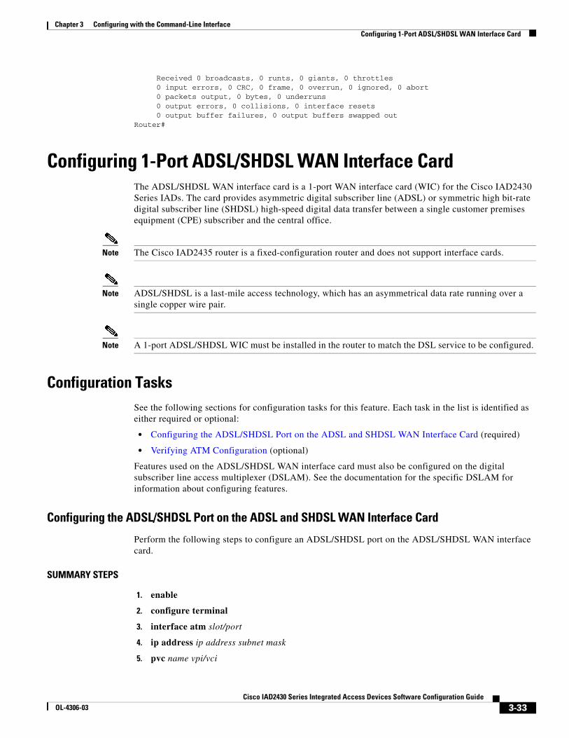
Received 0 broadcasts, 0 runts, 0 giants, 0 throttles 0 input errors, 0 CRC, 0 frame, 0 overrun, 0 ignored, 0 abort 0 packets output, 0 bytes, 0 underruns 0 output errors, 0 collisions, 0 interface resets 0 output buffer failures, 0 output buffers swapped outRouter#
Configuring 1-Port ADSL/SHDSL WAN Interface CardThe ADSL/SHDSL WAN interface card is a 1-port WAN interface card (WIC) for the Cisco IAD2430 Series IADs. The card provides asymmetric digital subscriber line (ADSL) or symmetric high bit-rate digital subscriber line (SHDSL) high-speed digital data transfer between a single customer premises equipment (CPE) subscriber and the central office.
Note The Cisco IAD2435 router is a fixed-configuration router and does not support interface cards.
Note ADSL/SHDSL is a last-mile access technology, which has an asymmetrical data rate running over a single copper wire pair.
Note A 1-port ADSL/SHDSL WIC must be installed in the router to match the DSL service to be configured.
Configuration TasksSee the following sections for configuration tasks for this feature. Each task in the list is identified as either required or optional:
• Configuring the ADSL/SHDSL Port on the ADSL and SHDSL WAN Interface Card (required)
• Verifying ATM Configuration (optional)
Features used on the ADSL/SHDSL WAN interface card must also be configured on the digital subscriber line access multiplexer (DSLAM). See the documentation for the specific DSLAM for information about configuring features.
Configuring the ADSL/SHDSL Port on the ADSL and SHDSL WAN Interface Card
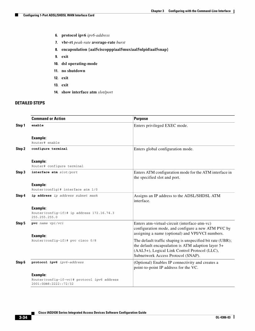
Perform the following steps to configure an ADSL/SHDSL port on the ADSL/SHDSL WAN interface card.
SUMMARY STEPS
1. enable
2. configure terminal
3. interface atm slot/port
4. ip address ip address subnet mask
5. pvc name vpi/vci
3-33Cisco IAD2430 Series Integrated Access Devices Software Configuration Guide
OL-4306-03
Chapter 3 Configuring with the Command-Line Interface Configuring 1-Port ADSL/SHDSL WAN Interface Card
6. protocol ipv6 ipv6-address
7. vbr-rt peak-rate average-rate burst
8. encapsulation {aal5ciscoppp|aal5mux|aal5nlpid|aal5snap}
9. exit
10. dsl operating-mode
11. no shutdown
12. exit
13. exit
14. show interface atm slot/port
DETAILED STEPS
Command or Action Purpose
Step 1 enable
Example:Router# enable
Enters privileged EXEC mode.
Step 2 configure terminal
Example:Router# configure terminal
Enters global configuration mode.
Step 3 interface atm slot/port
Example:Router(config)# interface atm 1/0
Enters ATM configuration mode for the ATM interface in the specified slot and port.
Step 4 ip address ip address subnet mask
Example:Router(config-if)# ip address 172.16.74.3 255.255.255.0
Assigns an IP address to the ADSL/SHDSL ATM interface.
Step 5 pvc name vpi/vci
Example:Router(config-if)# pvc cisco 0/8
Enters atm-virtual-circuit (interface-atm-vc) configuration mode, and configure a new ATM PVC by assigning a name (optional) and VPI/VCI numbers.
The default traffic shaping is unspecified bit rate (UBR); the default encapsulation is ATM adaption layer 5+ (AAL5+), Logical Link Control Protocol (LLC), Subnetwork Access Protocol (SNAP).
Step 6 protocol ipv6 ipv6-address
Example:Router(config-if-vc)# protocol ipv6 address 2001:0DB8:2222::72/32
(Optional) Enables IP connectivity and creates a point-to-point IP address for the VC.
3-34Cisco IAD2430 Series Integrated Access Devices Software Configuration Guide
OL-4306-03
Chapter 3 Configuring with the Command-Line Interface Configuring 1-Port ADSL/SHDSL WAN Interface Card
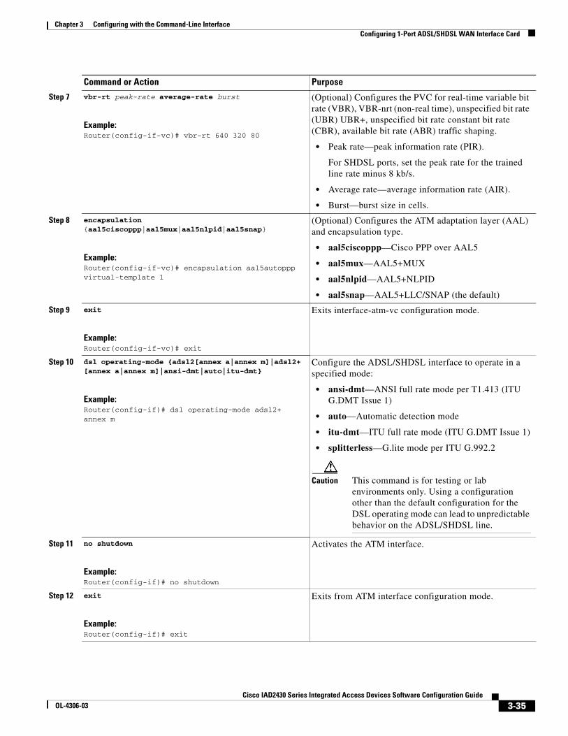
Step 7 vbr-rt peak-rate average-rate burst
Example:Router(config-if-vc)# vbr-rt 640 320 80
(Optional) Configures the PVC for real-time variable bit rate (VBR), VBR-nrt (non-real time), unspecified bit rate (UBR) UBR+, unspecified bit rate constant bit rate (CBR), available bit rate (ABR) traffic shaping.
• Peak rate—peak information rate (PIR).
For SHDSL ports, set the peak rate for the trained line rate minus 8 kb/s.
• Average rate—average information rate (AIR).
• Burst—burst size in cells.
Step 8 encapsulation {aal5ciscoppp|aal5mux|aal5nlpid|aal5snap}
Example:Router(config-if-vc)# encapsulation aal5autoppp virtual-template 1
(Optional) Configures the ATM adaptation layer (AAL) and encapsulation type.
• aal5ciscoppp—Cisco PPP over AAL5
• aal5mux—AAL5+MUX
• aal5nlpid—AAL5+NLPID
• aal5snap—AAL5+LLC/SNAP (the default)
Step 9 exit
Example:Router(config-if-vc)# exit
Exits interface-atm-vc configuration mode.
Step 10 dsl operating-mode {adsl2[annex a|annex m]|adsl2+ [annex a|annex m]|ansi-dmt|auto|itu-dmt}
Example:Router(config-if)# dsl operating-mode adsl2+ annex m
Configure the ADSL/SHDSL interface to operate in a specified mode:
• ansi-dmt—ANSI full rate mode per T1.413 (ITU G.DMT Issue 1)
• auto—Automatic detection mode
• itu-dmt—ITU full rate mode (ITU G.DMT Issue 1)
• splitterless—G.lite mode per ITU G.992.2
Caution This command is for testing or lab environments only. Using a configuration other than the default configuration for the DSL operating mode can lead to unpredictable behavior on the ADSL/SHDSL line.
Step 11 no shutdown
Example:Router(config-if)# no shutdown
Activates the ATM interface.
Step 12 exit
Example:Router(config-if)# exit
Exits from ATM interface configuration mode.
Command or Action Purpose
3-35Cisco IAD2430 Series Integrated Access Devices Software Configuration Guide
OL-4306-03
Chapter 3 Configuring with the Command-Line Interface Configuring 1-Port ADSL/SHDSL WAN Interface Card
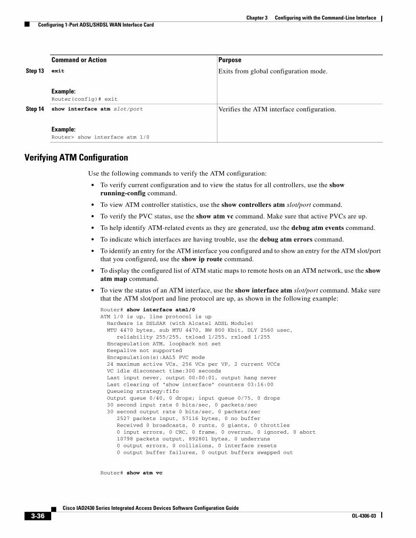
Verifying ATM Configuration
Use the following commands to verify the ATM configuration:
• To verify current configuration and to view the status for all controllers, use the show running-config command.
• To view ATM controller statistics, use the show controllers atm slot/port command.
• To verify the PVC status, use the show atm vc command. Make sure that active PVCs are up.
• To help identify ATM-related events as they are generated, use the debug atm events command.
• To indicate which interfaces are having trouble, use the debug atm errors command.
• To identify an entry for the ATM interface you configured and to show an entry for the ATM slot/port that you configured, use the show ip route command.
• To display the configured list of ATM static maps to remote hosts on an ATM network, use the show atm map command.
• To view the status of an ATM interface, use the show interface atm slot/port command. Make sure that the ATM slot/port and line protocol are up, as shown in the following example:
Router# show interface atm1/0ATM 1/0 is up, line protocol is up Hardware is DSLSAR (with Alcatel ADSL Module) MTU 4470 bytes, sub MTU 4470, BW 800 Kbit, DLY 2560 usec, reliability 255/255, txload 1/255, rxload 1/255 Encapsulation ATM, loopback not set Keepalive not supported Encapsulation(s):AAL5 PVC mode 24 maximum active VCs, 256 VCs per VP, 2 current VCCs VC idle disconnect time:300 seconds Last input never, output 00:00:01, output hang never Last clearing of "show interface" counters 03:16:00 Queueing strategy:fifo Output queue 0/40, 0 drops; input queue 0/75, 0 drops 30 second input rate 0 bits/sec, 0 packets/sec 30 second output rate 0 bits/sec, 0 packets/sec 2527 packets input, 57116 bytes, 0 no buffer Received 0 broadcasts, 0 runts, 0 giants, 0 throttles 0 input errors, 0 CRC, 0 frame, 0 overrun, 0 ignored, 0 abort 10798 packets output, 892801 bytes, 0 underruns 0 output errors, 0 collisions, 0 interface resets 0 output buffer failures, 0 output buffers swapped out
Router# show atm vc
Step 13 exit
Example:Router(config)# exit
Exits from global configuration mode.
Step 14 show interface atm slot/port
Example:Router> show interface atm 1/0
Verifies the ATM interface configuration.
Command or Action Purpose
3-36Cisco IAD2430 Series Integrated Access Devices Software Configuration Guide
OL-4306-03
Chapter 3 Configuring with the Command-Line Interface Configuring a VIC2-2BRI-NT/TE Card
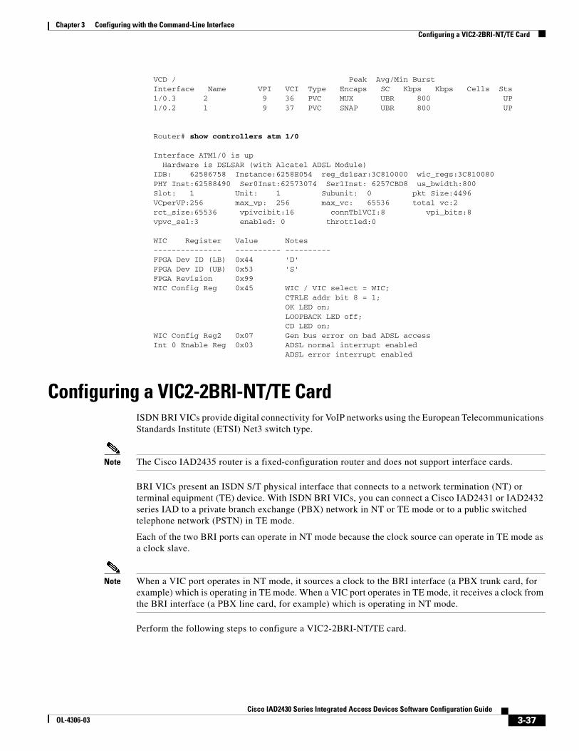
VCD / Peak Avg/Min BurstInterface Name VPI VCI Type Encaps SC Kbps Kbps Cells Sts1/0.3 2 9 36 PVC MUX UBR 800 UP1/0.2 1 9 37 PVC SNAP UBR 800 UP
Router# show controllers atm 1/0
Interface ATM1/0 is up Hardware is DSLSAR (with Alcatel ADSL Module)IDB: 62586758 Instance:6258E054 reg_dslsar:3C810000 wic_regs:3C810080PHY Inst:62588490 Ser0Inst:62573074 Ser1Inst: 6257CBD8 us_bwidth:800 Slot: 1 Unit: 1 Subunit: 0 pkt Size:4496 VCperVP:256 max_vp: 256 max_vc: 65536 total vc:2 rct_size:65536 vpivcibit:16 connTblVCI:8 vpi_bits:8 vpvc_sel:3 enabled: 0 throttled:0
WIC Register Value Notes--------------- ---------- ----------FPGA Dev ID (LB) 0x44 'D'FPGA Dev ID (UB) 0x53 'S'FPGA Revision 0x99 WIC Config Reg 0x45 WIC / VIC select = WIC; CTRLE addr bit 8 = 1; OK LED on; LOOPBACK LED off; CD LED on; WIC Config Reg2 0x07 Gen bus error on bad ADSL accessInt 0 Enable Reg 0x03 ADSL normal interrupt enabled ADSL error interrupt enabled
Configuring a VIC2-2BRI-NT/TE CardISDN BRI VICs provide digital connectivity for VoIP networks using the European Telecommunications Standards Institute (ETSI) Net3 switch type.
Note The Cisco IAD2435 router is a fixed-configuration router and does not support interface cards.
BRI VICs present an ISDN S/T physical interface that connects to a network termination (NT) or terminal equipment (TE) device. With ISDN BRI VICs, you can connect a Cisco IAD2431 or IAD2432 series IAD to a private branch exchange (PBX) network in NT or TE mode or to a public switched telephone network (PSTN) in TE mode.
Each of the two BRI ports can operate in NT mode because the clock source can operate in TE mode as a clock slave.
Note When a VIC port operates in NT mode, it sources a clock to the BRI interface (a PBX trunk card, for example) which is operating in TE mode. When a VIC port operates in TE mode, it receives a clock from the BRI interface (a PBX line card, for example) which is operating in NT mode.
Perform the following steps to configure a VIC2-2BRI-NT/TE card.
3-37Cisco IAD2430 Series Integrated Access Devices Software Configuration Guide
OL-4306-03
Chapter 3 Configuring with the Command-Line Interface Configuring a VIC2-2BRI-NT/TE Card
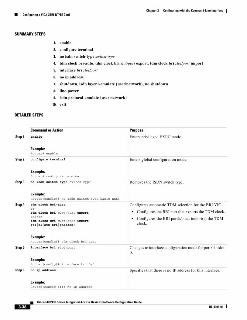
SUMMARY STEPS
1. enable
2. configure terminal
3. no isdn switch-type switch-type
4. tdm clock bri-auto, tdm clock bri slot/port export, tdm clock bri slot/port import
5. interface bri slot/port
6. no ip address
7. shutdown, isdn layer1-emulate {user|network}, no shutdown
8. line-power
9. isdn protocol-emulate {user|network}
10. exit
DETAILED STEPS
Command or Action Purpose
Step 1 enable
Example:Router# enable
Enters privileged EXEC mode.
Step 2 configure terminal
Example:Router# configure terminal
Enters global configuration mode.
Step 3 no isdn switch-type switch-type
Example:Router(config)# no isdn switch-type basic-net3
Removes the ISDN switch type.
Step 4 tdm clock bri-autoortdm clock bri slot/port exportand/ortdm clock bri slot/port import {t1|e1|atm|bri|onboard}
Example:Router(config)# tdm clock bri-auto
Configures automatic TDM selection for the BRI VIC.
• Configures the BRI port that exports the TDM clock.
• Configures the BRI port(s) that import(s) the TDM clock.
Step 5 interface bri slot/port
Example:Router(config)# interface bri 0/0
Changes to interface configuration mode for port 0 in slot 0.
Step 6 no ip address
Example:Router(config-if)# no ip address
Specifies that there is no IP address for this interface.
3-38Cisco IAD2430 Series Integrated Access Devices Software Configuration Guide
OL-4306-03
Chapter 3 Configuring with the Command-Line Interface Saving Configuration Changes
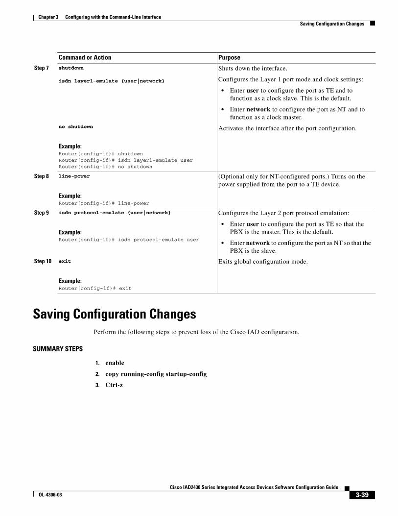
Saving Configuration ChangesPerform the following steps to prevent loss of the Cisco IAD configuration.
SUMMARY STEPS
1. enable
2. copy running-config startup-config
3. Ctrl-z
Step 7 shutdown
isdn layer1-emulate {user|network}
no shutdown
Example:Router(config-if)# shutdownRouter(config-if)# isdn layer1-emulate userRouter(config-if)# no shutdown
Shuts down the interface.
Configures the Layer 1 port mode and clock settings:
• Enter user to configure the port as TE and to function as a clock slave. This is the default.
• Enter network to configure the port as NT and to function as a clock master.
Activates the interface after the port configuration.
Step 8 line-power
Example:Router(config-if)# line-power
(Optional only for NT-configured ports.) Turns on the power supplied from the port to a TE device.
Step 9 isdn protocol-emulate {user|network}
Example:Router(config-if)# isdn protocol-emulate user
Configures the Layer 2 port protocol emulation:
• Enter user to configure the port as TE so that the PBX is the master. This is the default.
• Enter network to configure the port as NT so that the PBX is the slave.
Step 10 exit
Example:Router(config-if)# exit
Exits global configuration mode.
Command or Action Purpose
3-39Cisco IAD2430 Series Integrated Access Devices Software Configuration Guide
OL-4306-03
Chapter 3 Configuring with the Command-Line Interface Saving Configuration Changes
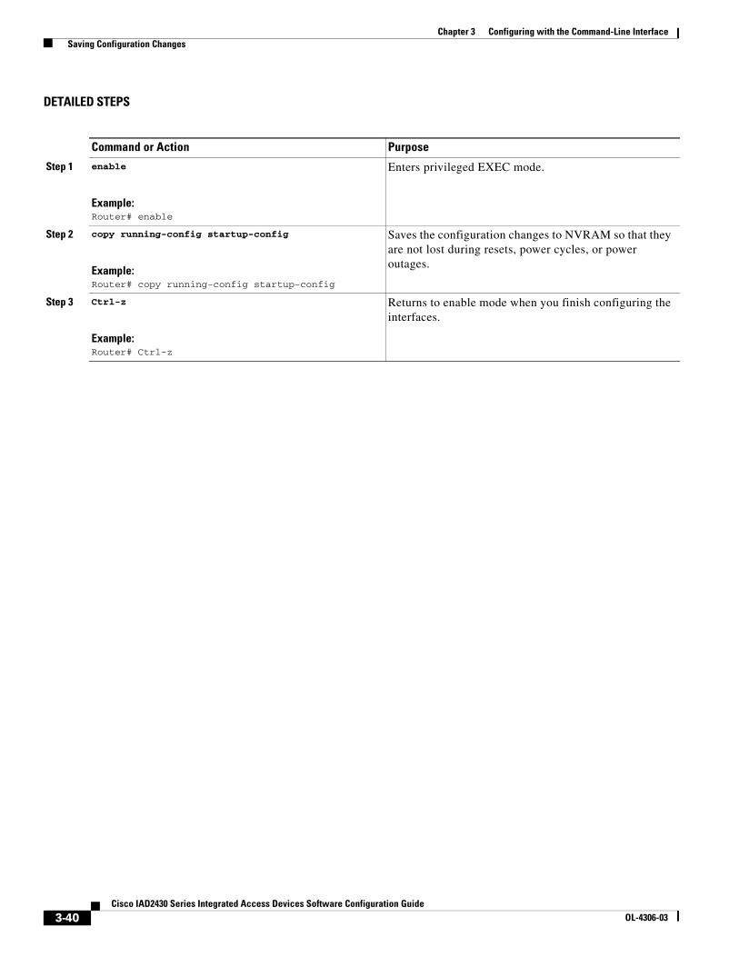
DETAILED STEPS
Command or Action Purpose
Step 1 enable
Example:Router# enable
Enters privileged EXEC mode.
Step 2 copy running-config startup-config
Example:Router# copy running-config startup-config
Saves the configuration changes to NVRAM so that they are not lost during resets, power cycles, or power outages.
Step 3 Ctrl-z
Example:Router# Ctrl-z
Returns to enable mode when you finish configuring the interfaces.
3-40Cisco IAD2430 Series Integrated Access Devices Software Configuration Guide
OL-4306-03

Chapter 3 Configuring with the Command-Line Interface Saving Configuration Changes
3-41Cisco IAD2430 Series Integrated Access Devices Software Configuration Guide
OL-4306-03

Chapter 3 Configuring with the Command-Line Interface Saving Configuration Changes
3-42Cisco IAD2430 Series Integrated Access Devices Software Configuration Guide
OL-4306-03