Embed Size (px)
Citation preview

C H A P T E R 17
Configuring Transport & Network Layer PreprocessingYou configure most transport at network layer preprocessors in a network analysis policy, which prepares traffic for inspection using the rules enabled in an intrusion policy. See Understanding Network Analysis and Intrusion Policies, page 11-1 for more information.
Transport and network layer preprocessors detect attacks that exploit IP fragmentation, checksum validation, and TCP and UDP session preprocessing. Before packets are sent to preprocessors, the packet decoder converts packet headers and payloads into a format that can be easily used by the preprocessors and the intrusion rules engine and detects various anomalous behaviors in packet headers. After packet decoding and before sending packets to other preprocessors, the inline normalization preprocessor normalizes traffic for inline deployments.
You can tailor transport and network layer preprocessor settings that you configure in network analysis policies by zone, or network. Some transport and network layer settings apply globally to all traffic, and you configure these in an access control policy.
• Configuring Advanced Transport/Network Settings, page 17-1
• Verifying Checksums, page 17-4
• Normalizing Inline Traffic, page 17-6
• Defragmenting IP Packets, page 17-11
• Understanding Packet Decoding, page 17-16
• Using TCP Stream Preprocessing, page 17-20
• Using UDP Stream Preprocessing, page 17-31
Configuring Advanced Transport/Network SettingsLicense: Protection
Advanced transport and network preprocessor settings apply globally to all networks, and zones where you apply your access control policy. You configure these advanced settings in an access control policy rather than in a network analysis policy.
The following sections describe these settings:
• Initiating Active Responses with Intrusion Drop Rules, page 17-2
• Troubleshooting: Logging Session Termination Messages, page 17-3
17-1ASA FirePOWER Module User Guide
Chapter 17 Configuring Transport & Network Layer Preprocessing Configuring Advanced Transport/Network Settings
Initiating Active Responses with Intrusion Drop RulesLicense: Protection
A drop rule is an intrusion rule or preprocessor rule whose rule state is set to Drop and Generate Events. In an inline deployment, the system responds to TCP or UDP drop rules by dropping the triggering packet and blocking the session where the packet originated. In a passive deployment, the system cannot drop the packet and does not block the session except with the use of active responses.
Tip Because UDP data streams are not typically thought of in terms of sessions, see Using UDP Stream Preprocessing, page 17-31 for further explanation of how the stream preprocessor uses the source and destination IP address fields in the encapsulating IP datagram header and the port fields in the UDP header to determine the direction of flow and identify a UDP session.
You can configure the Maximum Active Responses option to initiate one or more active responses to more precisely and specifically close a TCP connection or UDP session when an offending packet triggers a TCP or UDP drop rule.
When active responses are enabled in an inline deployment, the system responds to TCP drop rules by dropping the triggering packet and inserting a TCP Reset (RST) packet in both the client and server traffic. The system cannot drop the packet in a passive deployment; when active responses are enabled in a passive deployment, the system responds to TCP drop rules by sending a TCP reset to both the client and server ends of a TCP connection. When active responses are enabled in inline or passive deployments, the system closes a UDP session by sending an ICMP unreachable packet to each end of the session. Active responses are most effective in inline deployments because resets are more likely to arrive in time to affect the connection or session.
Depending on how you configure the Maximum Active Responses option, the system can also initiate additional active responses if it sees additional traffic from either end of the connection or session. The system initiates each additional active response, up to a specified maximum, after a specified number of seconds have elapsed since the previous response.
See Selecting The TCP Global Option, page 17-21 for information on setting the maximum number of active responses.
Note that a triggered resp or react rule also initiates an active response regardless of the configuration of Maximum Active Responses; however, Maximum Active Responses control whether the system initiates additional active responses for resp and react rules in the same way it controls the maximum number of active responses for drop rules. See Initiating Active Responses with Rule Keywords, page 23-83 for more information.
You can also use the config response command to configure the active response interface to use and the number of TCP resets to attempt in a passive deployment. See Setting the Active Response Reset Attempts and Interface, page 23-86 for more information.
No preprocessor rules are associated with the following options.
Maximum Active Responses
Specifies a maximum of 1 to 25 active responses per TCP connection. When additional traffic occurs on a connection where an active response has been initiated, and the traffic occurs more than Minimum Response Seconds after a previous active response, the system sends another active response unless the specified maximum has been reached. A setting of 0 disables active responses triggered by drop rules and disables additional active responses triggered by resp or react rules. For more information, see Initiating Active Responses with Intrusion Drop Rules, page 17-2 and Initiating Active Responses with Rule Keywords, page 23-83.
17-2ASA FirePOWER Module User Guide

Chapter 17 Configuring Transport & Network Layer Preprocessing Configuring Advanced Transport/Network Settings
Minimum Response Seconds
Until Maximum Active Responses occur, specifies waiting 1 to 300 seconds before any additional traffic on a connection where the system has initiated an active response results in a subsequent active response.
To initiate active responses with drop rules:
Step 1 Select Configuration > ASA FirePOWER Configuration > Policies > Access Control Policy.
The Access Control Policy page appears.
Step 2 Click the edit icon ( ) next to the access control policy you want to edit.
The access control policy editor appears.
Step 3 Select the Advanced tab.
The access control policy advanced settings page appears.
Step 4 Click the edit icon ( ) next to Network Analysis and Intrusion Policies.
The Network Analysis and Intrusion Policies pop-up window appears.
Step 5 Click Network Analysis Policy List.
The Network Analysis Policy List pop-up window appears.
Step 6 Click the edit icon ( ) next to the access control policy you want to edit.
The access control policy editor appears.
Step 7 Select the Advanced tab.
The access control policy advanced settings page appears.
Step 8 Click the edit icon ( ) next to Transport/Network Layer Preprocessor Settings.
The Transport/Network Layer Preprocessor Settings pop-up window appears.
Step 9 You have the following options:
• Specify a value 1 to 25 of Maximum Active Responses per TCP connection. A setting of 0 disables active responses triggered by drop rules and disables additional active responses triggered by resp or react rules.
• Specify a value 1 to 300 of Minimum Response Seconds to wait until either Maximum Active Responses occur or any additional traffic on a connection where the system has initiated an active response results in a subsequent active response.
Step 10 Click OK.
You must apply the access control policy for your changes to take effect; see Applying an Access Control Policy, page 4-10.
Troubleshooting: Logging Session Termination MessagesLicense: Protection
Support might ask you during a troubleshooting call to configure your system to log a message when an individual connection exceeds the specified threshold. Changing the setting for this option will affect performance and should be done only with Support guidance.
17-3ASA FirePOWER Module User Guide

Chapter 17 Configuring Transport & Network Layer Preprocessing Verifying Checksums
To log session termination messages:
Step 1 Select Configuration > ASA FirePOWER Configuration > Policies > Access Control Policy.
The Access Control Policy page appears.
Step 2 Click the edit icon ( ) next to the access control policy you want to edit.
The access control policy editor appears.
Step 3 Select the Advanced tab.
The access control policy advanced settings page appears.
Step 4 Click the edit icon ( ) next to Network Analysis and Intrusion Policies.
The Network Analysis and Intrusion Policies pop-up window appears.
Step 5 Click Network Analysis Policy List.
The Network Analysis Policy List pop-up window appears.
Step 6 Click the edit icon ( ) next to the access control policy you want to edit.
The access control policy editor appears.
Step 7 Select the Advanced tab.
The access control policy advanced settings page appears.
Step 8 Click the edit icon ( ) next to Transport/Network Layer Preprocessor Settings.
The Transport/Network Layer Preprocessor Settings pop-up window appears.
Step 9 Expand Troubleshooting Options.
Step 10 Specify for Session Termination Logging Threshold the number of bytes that result in a logged message when the session terminates and the specified number was exceeded.
The upper limit of 1GB is also restricted by the amount of memory on the device allocated for stream processing.
Step 11 Click OK.
You must apply the access control policy for your changes to take effect; see Applying an Access Control Policy, page 4-10.
Verifying ChecksumsLicense: Protection
The system can verify all protocol-level checksums to ensure that complete IP, TCP, UDP, and ICMP transmissions are received and that, at a basic level, packets have not been tampered with or accidentally altered in transit. A checksum uses an algorithm to verify the integrity of a protocol in the packet. The packet is considered to be unchanged if the system computes the same value that is written in the packet by the end host.
Disabling checksum verification may leave your network susceptible to insertion attacks. Note that the system does not generate checksum verification events. In an inline deployment, you can configure the system to drop packets with invalid checksums.
17-4ASA FirePOWER Module User Guide

Chapter 17 Configuring Transport & Network Layer Preprocessing Verifying Checksums
To configure checksum verifications:
Step 1 Select Configuration > ASA FirePOWER Configuration > Policies > Access Control Policy.
The Access Control Policy page appears.
Step 2 Click the edit icon ( ) next to the access control policy you want to edit.
The access control policy editor appears.
Step 3 Select the Advanced tab.
The access control policy advanced settings page appears.
Step 4 Click the edit icon ( ) next to Network Analysis and Intrusion Policies.
The Network Analysis and Intrusion Policies pop-up window appears.
Step 5 Click Network Analysis Policy List.
The Network Analysis Policy List pop-up window appears.
Step 6 Click the edit icon ( ) next to the policy you want to edit.
If you have unsaved changes in another policy, click OK to discard those changes and continue. See Resolving Conflicts and Committing Policy Changes, page 11-15 for information on saving unsaved changes in another policy.
The Edit Policy page appears.
Step 7 Click Settings in the navigation panel on the left.
The Settings page appears.
Step 8 You have two choices, depending on whether Checksum Verification under Transport/Network Layer Preprocessors is enabled:
• If the configuration is enabled, click Edit.
• If the configuration is disabled, click Enabled, then click Edit.
The Checksum Verification page appears. A message at the bottom of the page identifies the policy layer that contains the configuration. See Using Layers in a Network Analysis or Intrusion Policy, page 12-1 for more information.
Step 9 You can set any of the options in the Checksum Verification section to Enabled or Disabled in a passive or inline deployment, or to Drop in an inline deployment:
• ICMP Checksums
• IP Checksums
• TCP Checksums
• UDP Checksums
Note that to drop offending packets, in addition to setting an option to Drop you must also enable Inline Mode in the associated network analysis policy. See Allowing Preprocessors to Affect Traffic in Inline Deployments, page 14-5 for more information. Note also that setting these options to Drop in a passive deployment is the same as setting them to Enabled.
Step 10 Save your policy, continue editing, discard your changes, revert to the default configuration settings in the base policy, or exit while leaving your changes in the system cache. See Resolving Conflicts and Committing Policy Changes, page 11-15 for more information.
17-5ASA FirePOWER Module User Guide

Chapter 17 Configuring Transport & Network Layer Preprocessing Normalizing Inline Traffic
Normalizing Inline TrafficLicense: Protection
The inline normalization preprocessor normalizes traffic to minimize the chances of attackers evading detection in inline deployments. If you enable the inline normalization preprocessor in a network analysis policy, the system tests the following two conditions to ensure that you are using an inline deployment:
• Inline Mode is enabled in the policy. See Allowing Preprocessors to Affect Traffic in Inline Deployments, page 14-5.
• The access control policy where inline normalization is enabled is applied to a device that is deployed inline.
The preprocessor normalizes specified traffic only when both conditions are met.
You can specify normalization of any combination of IPv4, IPv6, ICMPv4, ICMPv6, and TCP traffic. Most normalizations are on a per-packet basis and are conducted by the inline normalization preprocessor. However, the TCP stream preprocessor handles most state-related packet and stream normalizations, including TCP payload normalization.
Inline normalization takes place immediately after decoding by the packet decoder and before processing by other preprocessors. Normalization proceeds from the inner to outer packet layers.
The inline normalization preprocessor does not generate events; it prepares packets for use by other preprocessors and the rules engine in inline deployments. The preprocessor also helps ensure that the packets the system processes are the same as the packets received by the hosts on your network.
Tip In an inline deployment, Cisco recommends that you configure the inline normalization preprocessor with the Normalize TCP Payload option enabled. In a passive deployment, Cisco recommends that you configure adaptive profiles. For more information, see Tuning Preprocessing in Passive Deployments, page 18-1.
Minimum TTL
When Reset TTL is greater than or equal to the value 1 to 255 set for this option, specifies the following:
• the minimum value the system will permit in the IPv4 Time to Live (TTL) field when Normalize IPv4 is enabled; a lower value results in normalizing the packet value for TTL to the value set for Reset TTL
• the minimum value the system will permit in the IPv6 Hop Limit field when Normalize IPv6 is enabled; a lower value results in normalizing the packet value for Hop Limit to the value set for Reset TTL
The system assumes a value of 1 when the field is empty.
Note that you can enable the following rules in the decoder rule category to generate events for this option:
• You can enable rule 116:428 to generate an event when the system detects an IPv4 packet with a TTL less than the specified minimum.
• You can enable rule 116:270 to generate an event when the system detects an IPv6 packet with a hop limit that is less than the specified minimum.
See the packet decoder Detect Protocol Header Anomalies option in Configuring Packet Decoding, page 17-19 for more information.
17-6ASA FirePOWER Module User Guide

Chapter 17 Configuring Transport & Network Layer Preprocessing Normalizing Inline Traffic
Reset TTL
When set to a value 1 to 255 that is greater than or equal to Minimum TTL, normalizes the following:
• the IPv4 TTL field when Normalize IPv4 is enabled
• the IPv6 Hop Limit field when Normalize IPv6 is enabled
The system normalizes the packet by changing its TTL or Hop Limit value to the value set for this option when the packet value is less than Minimum TTL. Setting this option to a value of 0, or any value less than Minimum TTL, disables the option. The system assumes a value of 0 when the field is empty.
Normalize IPv4
Enables normalization of IPv4 traffic. The system also normalizes the TTL field as needed when this option is enabled and the value set for Reset TTL enables TTL normalization. You can also enable Normalize Don’t Fragment Bits and Normalize Reserved Bits when this option is enabled.
When you enable this option, the system performs the following base IPv4 normalizations:
• truncates packets with excess payload to the datagram length specified in the IP header
• clears the Differentiated Services (DS) field, formerly known as the Type of Service (TOS) field
• sets all option octets to 1 (No Operation)
Normalize Don't Fragment Bit
Clears the single-bit Don’t Fragment subfield of the IPv4 Flags header field. Enabling this option allows a downstream router to fragment packets if necessary instead of dropping them; enabling this option can also prevent evasions based on crafting packets to be dropped. You must enable Normalize IPv4 to select this option.
Normalize Reserved Bit
Clears the single-bit Reserved subfield of the IPv4 Flags header field. You would typically enable this option. You must enable Normalize IPv4 to select this option.
Normalize TOS Bit
Clears the one byte Differentiated Services field, formerly known as Type of Service. You must enable Normalize IPv4 to select this option.
Normalize Excess Payload
Truncates packets with excess payload to the datagram length specified in the IP header plus the Layer 2 (for example, Ethernet) header, but does not truncate below the minimum frame length. You must enable Normalize IPv4 to select this option.
Normalize IPv6
Sets all Option Type fields in the Hop-by-Hop Options and Destination Options extension headers to 00 (Skip and continue processing). The system also normalizes the Hop Limit field as needed when this option is enabled and the value set for Reset TTL enables hop limit normalization.
Normalize ICMPv4
Clears the 8-bit Code field in Echo (Request) and Echo Reply messages in ICMPv4 traffic.
Normalize ICMPv6
Clears the 8-bit Code field in Echo (Request) and Echo Reply messages in ICMPv6 traffic.
17-7ASA FirePOWER Module User Guide

Chapter 17 Configuring Transport & Network Layer Preprocessing Normalizing Inline Traffic
Normalize/Clear Reserved Bits
Clears the Reserved bits in the TCP header.
Normalize/Clear Option Padding Bytes
Clears any TCP option padding bytes.
Clear Urgent Pointer if URG=0
Clears the 16-bit TCP header Urgent Pointer field if the urgent (URG) control bit is not set.
Clear Urgent Pointer/URG on Empty Payload
Clears the TCP header Urgent Pointer field and the URG control bit if there is no payload.
Clear URG if Urgent Pointer is Not Set
Clears the TCP header URG control bit if the urgent pointer is not set.
Normalize Urgent Pointer
Sets the two-byte TCP header Urgent Pointer field to the payload length if the pointer is greater than the payload length.
Normalize TCP Payload
Enables normalization of the TCP Data field to ensure consistency in retransmitted data. Any segments that cannot be properly reassembled are dropped.
Remove Data on SYN
Removes data in synchronization (SYN) packets if your TCP operating system policy is not Mac OS.
This option also disables event generation for rule 129:2.
Remove Data on RST
Removes any data from a TCP reset (RST) packet.
Trim Data to Window
Trims the TCP Data field to the size specified in the Window field.
Trim Data to MSS
Trims the TCP Data field to the Maximum Segment Size (MSS) if the payload is longer than MSS.
Block Unrecoverable TCP Header Anomalies
When you enable this option, the system blocks anomalous TCP packets that, if normalized, would be invalid and likely would be blocked by the receiving host. For example, the system blocks any SYN packet transmitted subsequent to an established session.
The system also drops any packet that matches any of the following TCP stream preprocessor rules, regardless of whether the rules are enabled:
– 129:1
– 129:3
– 129:4
– 129:6
17-8ASA FirePOWER Module User Guide

Chapter 17 Configuring Transport & Network Layer Preprocessing Normalizing Inline Traffic
– 129:8
– 129:11
– 129:14 through 129:19
The Total Blocked Packets performance graph tracks the number of packets blocked in inline deployments and, in passive deployments, the number that would have been blocked in an inline deployment.
Explicit Congestion Notification
Enables per-packet or per-stream normalization of Explicit Congestion Notification (ECN) flags as follows:
• select Packet to clear ECN flags on a per-packet basis regardless of negotiation
• select Stream to clear ECN flags on a per-stream basis if ECN use was not negotiated
If you select Stream, you must also ensure that the TCP stream preprocessor Require TCP 3-Way Handshake option is enabled for this normalization to take place; see Selecting TCP Policy Options, page 17-22 for more information.
Allow These TCP Options
Disables normalization of specific TCP options you allow in traffic.
The system does not normalize options that you explicitly allow. It normalizes options that you do not explicitly allow by setting the options to No Operation (TCP Option 1).
The system always allows the Maximum Segment Size (MSS), Window Scale, and Time Stamp TCP options because these options are commonly used for optimal TCP performance. The system normalizes these commonly used options regardless of the configuration of Allow These TCP Options. The system does not automatically allow other less commonly used options.
You can allow specific options by configuring a comma-separated list of option keywords, option numbers, or both as shown in the following example:
sack, echo, 19
Specifying an option keyword is the same as specifying the number for one or more TCP options associated with the keyword. For example, specifying sack is the same as specifying TCP options 4 (Selective Acknowledgment Permitted) and 5 (Selective Acknowledgment). Option keywords are not case sensitive.
You can also specify any, which allows all TCP options and effectively disables normalization of all TCP options.
The following table summarizes how you can specify TCP options to allow. If you leave the field empty, the system allows only the MSS, Window Scale, and Time Stamp options.
Specify... To allow...
sack TCP options 4 (Selective Acknowledgment Permitted) and 5 (Selective Acknowledgment)
echo TCP options 6 (Echo Request) and 7 (Echo Reply)
partial_order TCP options 9 (Partial Order Connection Permitted) and 10 (Partial Order Service Profile)
conn_count TCP Connection Count options 11 (CC), 12 (CC.New), and 13 (CC.Echo)
17-9ASA FirePOWER Module User Guide

Chapter 17 Configuring Transport & Network Layer Preprocessing Normalizing Inline Traffic
When you do not specify any for this option, normalizations include the following:
• except MSS, Window Scale, Time Stamp, and any explicitly allowed options, sets all option bytes to No Operation (TCP Option 1)
• sets the Time Stamp octets to No Operation if Time Stamp is present but invalid, or valid but not negotiated
• blocks the packet if Time Stamp is negotiated but not present
• clears the Time Stamp Echo Reply (TSecr) option field if the Acknowledgment (ACK) control bit is not set
• sets the MSS and Window Scale options to No Operation (TCP Option 1) if the SYN control bit is not set
To configure the inline normalizations preprocessor:
Step 1 Select Configuration > ASA FirePOWER Configuration > Policies > Access Control Policy.
The Access Control Policy page appears.
Step 2 Click the edit icon ( ) next to the access control policy you want to edit.
The access control policy editor appears.
Step 3 Select the Advanced tab.
The access control policy advanced settings page appears.
Step 4 Click the edit icon ( ) next to Network Analysis and Intrusion Policies.
The Network Analysis and Intrusion Policies pop-up window appears.
Step 5 Click Network Analysis Policy List.
The Network Analysis Policy List pop-up window appears.
Step 6 Click the edit icon ( ) next to the policy you want to edit.
If you have unsaved changes in another policy, click OK to discard those changes and continue. See Resolving Conflicts and Committing Policy Changes, page 11-15 for information on saving unsaved changes in another policy.
The Edit Policy page appears.
Step 7 Click Settings in the navigation panel on the left.
The Settings page appears.
Step 8 You have two choices depending on whether Inline Normalization is enabled under Transport/Network Layer Preprocessors:
alt_checksum TCP options 14 (Alternate Checksum Request) and 15 (Alternate Checksum)
md5 TCP option 19 (MD5 Signature)
the option number, 2 to 255
a specific option, including options for which there is no keyword
any all TCP options; this setting effectively disables TCP option normalization
Specify... To allow...
17-10ASA FirePOWER Module User Guide

Chapter 17 Configuring Transport & Network Layer Preprocessing Defragmenting IP Packets
• If the configuration is enabled, click Edit.
• If the configuration is disabled, click Enabled, then click Edit.
The Inline Normalization page appears. A message at the bottom of the page identifies the policy layer that contains the configuration. See Using Layers in a Network Analysis or Intrusion Policy, page 12-1 for more information.
Step 9 You can set any of the options described in Normalizing Inline Traffic, page 17-6.
Step 10 Save your policy, continue editing, discard your changes, revert to the default configuration settings in the base policy, or exit while leaving your changes in the system cache. See Resolving Conflicts and Committing Policy Changes, page 11-15 for more information.
Defragmenting IP PacketsLicense: Protection
When an IP datagram is broken into two or more smaller IP datagrams because it is larger than the maximum transmission unit (MTU), it is fragmented. A single IP datagram fragment may not contain enough information to identify a hidden attack. Attackers may attempt to evade detection by transmitting attack data in fragmented packets. The IP defragmentation preprocessor reassembles fragmented IP datagrams before the rules engine executes rules against them so the rules can more appropriately identify attacks in those packets. If fragmented datagrams cannot be reassembled, rules do not execute against them.
Note that you must enable IP defragmentation preprocessor rules, which have a generator ID (GID) of 123, if you want these rules to generate events. See Setting Rule States, page 20-19 for more information.
See the following sections for more information:
• Understanding IP Fragmentation Exploits, page 17-11
• Target-Based Defragmentation Policies, page 17-12
• Selecting Defragmentation Options, page 17-13
• Configuring IP Defragmentation, page 17-14
Understanding IP Fragmentation ExploitsLicense: Protection
Enabling IP defragmentation helps you detect attacks against hosts on your network, like the teardrop attack, and resource consumption attacks against the system itself, like the Jolt2 attack.
The Teardrop attack exploits a bug in certain operating systems that causes them to crash when trying to reassemble overlapping IP fragments. When enabled and configured to do so, the IP defragmentation preprocessor identifies the overlapping fragments. The IP defragmentation preprocessor detects the first packets in an overlapping fragment attack such as Teardrop, but does not detect subsequent packets for the same attack.
17-11ASA FirePOWER Module User Guide

Chapter 17 Configuring Transport & Network Layer Preprocessing Defragmenting IP Packets
The Jolt2 attack sends a large number of copies of the same fragmented IP packet in an attempt to overuse IP defragmentors and cause a denial of service attack. A memory usage cap disrupts this and similar attacks in the IP defragmentation preprocessor, and places the system self-preservation above exhaustive inspection. The system is not overwhelmed by the attack, remains operational, and continues to inspect network traffic.
Different operating systems reassemble fragmented packets in different ways. Attackers who can determine which operating systems your hosts are running can also fragment malicious packets so that a target host reassembles them in a specific manner. Because the system does not know which operating systems the hosts on your monitored network are running, the preprocessor may reassemble and inspect the packets incorrectly, thus allowing an exploit to pass through undetected. To mitigate this kind of attack, you can configure the defragmentation preprocessor to use the appropriate method of defragmenting packets for each host on your network. See Target-Based Defragmentation Policies, page 17-12 for more information.
Note that you can also use adaptive profiles to dynamically select target-based policies for the IP defragmentation preprocessor using host operating system information for the target host in a packet. For more information, see Tuning Preprocessing in Passive Deployments, page 18-1.
Target-Based Defragmentation PoliciesLicense: Protection
A host's operating system uses three criteria to determine which packet fragments to favor when reassembling the packet: the order in which the fragment was received by the operating system, its offset (the fragment's distance, in bytes, from the beginning of the packet), and its beginning and ending position compared to overlap fragments. Although every operating system uses these criteria, different operating systems favor different fragments when reassembling fragmented packets. Therefore, two hosts with different operating systems on your network could reassemble the same overlapping fragments in entirely different ways.
An attacker, aware of the operating system of one of your hosts, could attempt to evade detection and exploit that host by sending malicious content hidden in overlapping packet fragments. This packet, when reassembled and inspected, seems innocuous, but when reassembled by the target host, contains a malicious exploit. However, if you configure the IP defragmentation preprocessor to be aware of the operating systems running on your monitored network segment, it will reassemble the fragments the same way that the target host does, allowing it to identify the attack.
You can configure the IP defragmentation preprocessor to use one of seven defragmentation policies, depending on the operating system of the target host. The following table lists the seven policies and the operating systems that use each one. The First and Last policy names reflect whether those policies favor original or subsequent overlapping packets.
Table 17-1 Target-Based Defragmentation Policies
Policy Operating Systems
BSD AIX
FreeBSD
IRIX
VAX/VMS
BSD-right HP JetDirect
17-12ASA FirePOWER Module User Guide

Chapter 17 Configuring Transport & Network Layer Preprocessing Defragmenting IP Packets
Selecting Defragmentation OptionsLicense: Protection
You can choose to simply enable or disable IP defragmentation; however, Cisco recommends that you specify the behavior of the enabled IP defragmentation preprocessor at a more granular level.
If no preprocessor rule is mentioned in the following descriptions, the option is not associated with a preprocessor rule.
You can configure the global Preallocated Fragments option:
Preallocated Fragments
The maximum number of individual fragments that the preprocessor can process at once. Specifying the number of fragment nodes to preallocate enables static memory allocation.
Caution Processing an individual fragment uses approximately 1550 bytes of memory. If the preprocessor requires more memory to process the individual fragments than the predetermined allowable memory limit for the device, the memory limit for the device takes precedence.
You can configure the following options for each IP defragmentation policy:
Networks
The IP address of the host or hosts to which you want to apply the defragmentation policy.
You can specify a single IP address or address block, or a comma-separated list of either or both. You can specify up to 255 total profiles, including the default policy. For information on using IPv4 and IPv6 address blocks in the ASA FirePOWER module, see IP Address Conventions, page 1-4.
Note that the default setting in the default policy specifies all IP addresses on your monitored network segment that are not covered by another target-based policy. Therefore, you cannot and do not need to specify an IP address or CIDR block/prefix length for the default policy, and you cannot leave this setting blank in another policy or use address notation to represent any (for example, 0.0.0.0/0 or ::/0).
Note also that for a target-based policy to process traffic, the networks you identify must match or be a subset of the networks, and zones handled by the network analysis policy where you configure the target-based policy. See Customizing Preprocessing with Network Analysis Policies, page 13-2 for more information.
First Mac OS
HP-UX
Linux Linux
OpenBSD
Last Cisco IOS
Solaris SunOS
Windows Windows
Table 17-1 Target-Based Defragmentation Policies (continued)
Policy Operating Systems
17-13ASA FirePOWER Module User Guide
Chapter 17 Configuring Transport & Network Layer Preprocessing Defragmenting IP Packets
Policy
The defragmentation policy you want to use for a set of hosts on your monitored network segment. You can choose among seven policies: BSD, BSD-Right, First, Linux, Last, Solaris, and Windows. See Target-Based Defragmentation Policies, page 17-12 for detailed information on these policies.
Timeout
Specifies the maximum amount of time, in seconds, that the preprocessor engine can use when reassembling a fragmented packet. If the packet cannot be reassembled within the specified time period, the preprocessor engine stops attempting to reassemble the packet and discards received fragments.
Minimum TTL
Specifies the minimum acceptable TTL value a packet may have. This option detects TTL-based insertion attacks.
You can enable rule 123:1 to generate events for this option. See Setting Rule States, page 20-19 for more information.
Detect Anomalies
Identifies fragmentation problems such as overlapping fragments.
You can enable the following rules to generate events for this option:
• 123:1 through 123:4
• 123:5 (BSD policy)
• 123:6 through 123:8
Overlap Limit
Specifies that when the configured number between 0 (unlimited) and 255 of overlapping segments in a session has been detected, defragmentation stops for that session. You must enable Detect Anomalies to configure this option. A blank value disables this option.
You can enable rule 123:12 to generate events for this option. See Setting Rule States, page 20-19 for more information.
Minimum Fragment Size
Specifies that when a non-last fragment smaller than the configured number between 0 (unlimited) and 255 of bytes has been detected, the packet is considered malicious. You must enable Detect Anomalies to configure this option. A blank value disables this option.
You can enable rule 123:13 to generate events for this option. See Setting Rule States, page 20-19 for more information.
Configuring IP DefragmentationLicense: Protection
You can use the following procedure to configure the IP defragmentation preprocessor. For more information on the IP defragmentation preprocessor configuration options, see Selecting Defragmentation Options, page 17-13.
17-14ASA FirePOWER Module User Guide

Chapter 17 Configuring Transport & Network Layer Preprocessing Defragmenting IP Packets
To configure IP defragmentation:
Step 1 Select Configuration > ASA FirePOWER Configuration > Policies > Access Control Policy.
The Access Control Policy page appears.
Step 2 Click the edit icon ( ) next to the access control policy you want to edit.
The access control policy editor appears.
Step 3 Select the Advanced tab.
The access control policy advanced settings page appears.
Step 4 Click the edit icon ( ) next to Network Analysis and Intrusion Policies.
The Network Analysis and Intrusion Policies pop-up window appears.
Step 5 Click Network Analysis Policy List.
The Network Analysis Policy List pop-up window appears.
Step 6 Click the edit icon ( ) next to the policy you want to edit.
If you have unsaved changes in another policy, click OK to discard those changes and continue. See Resolving Conflicts and Committing Policy Changes, page 11-15 for information on saving unsaved changes in another policy.
The Edit Policy page appears.
Step 7 Click Settings in the navigation panel on the left.
The Settings page appears.
Step 8 You have two choices, depending on whether IP Defragmentation under Transport/Network Layer Preprocessors is enabled:
• If the configuration is enabled, click Edit.
• If the configuration is disabled, click Enabled, then click Edit.
The IP Defragmentation page appears. A message at the bottom of the page identifies the policy layer that contains the configuration. See Using Layers in a Network Analysis or Intrusion Policy, page 12-1 for more information.
Step 9 Optionally, you can modify the setting for Preallocated Fragments in the Global Settings page area.
Step 10 You have two options:
• Add a new target-based policy. Click the add icon ( ) next to Servers on the left side of the page. The Add Target pop-up window appears. Specify one or more IP addresses in the Host Address field and click OK.
You can specify a single IP address or address block, or a comma-separated list of either or both. You can create a total of 255 target-based policies including the default policy. For information on using IP address blocks in the ASA FirePOWER module, see IP Address Conventions, page 1-4.
Note that for a target-based policy to process traffic, the networks you identify must match or be a subset of the networks, and zones handled by the network analysis policy where you configure the target-based policy. See Customizing Preprocessing with Network Analysis Policies, page 13-2 for more information.
A new entry appears in the list of targets on the left side of the page, highlighted to indicate that it is selected, and the Configuration section updates to reflect the current configuration for the policy you added.
17-15ASA FirePOWER Module User Guide

Chapter 17 Configuring Transport & Network Layer Preprocessing Understanding Packet Decoding
• Modify the settings for an existing target-based policy. Click the configured address for a policy you have added under Hosts on the left side of the page, or click default.
Your selection is highlighted and the Configuration section updates to display the current configuration for the policy you selected. To delete an existing target-based policy, click the delete icon ( ) next to the policy you want to remove.
Step 11 Optionally, you can modify any of the options in the Configuration page area.
Step 12 Save your policy, continue editing, discard your changes, revert to the default configuration settings in the base policy, or exit while leaving your changes in the system cache. See Resolving Conflicts and Committing Policy Changes, page 11-15 for more information.
Understanding Packet DecodingLicense: Protection
Before sending captured packets to a preprocessor, the system first sends the packets to the packet decoder. The packet decoder converts packet headers and payloads into a format that preprocessors and the rules engine can easily use. Each stack layer is decoded in turn, beginning with the data link layer and continuing through the network and transport layers.
Note that you must enable packet decoder rules, which have a generator ID (GID) of 116, if you want these rules to generate events. See Setting Rule States, page 20-19 for more information.
If no preprocessor rule is mentioned in the following descriptions, the option is not associated with a preprocessor rule.
Decode GTP Data Channel
Decodes the encapsulated GTP (General Packet Radio Service [GPRS] Tunneling Protocol) data channel. By default, the decoder decodes version 0 data on port 3386 and version 1 data on port 2152. You can use the GTP_PORTS default variable to modify the ports that identify encapsulated GTP traffic. See Optimizing Predefined Default Variables, page 2-14 for more information.
You can enable rules 116:297 and 116:298 to generate events for this option.
Detect Teredo on Non-Standard Ports
Inspects Teredo tunneling of IPv6 traffic that is identified on a UDP port other than port 3544.
The system always inspects IPv6 traffic when it is present. By default, IPv6 inspection includes the 4in6, 6in4, 6to4, and 6in6 tunneling schemes, and also includes Teredo tunneling when the UDP header specifies port 3544.
In an IPv4 network, IPv4 hosts can use the Teredo protocol to tunnel IPv6 traffic through an IPv4 Network Address Translation (NAT) device. Teredo encapsulates IPv6 packets within IPv4 UDP datagrams to permit IPv6 connectivity behind an IPv4 NAT device. The system normally uses UDP port 3544 to identify Teredo traffic. However, an attacker could use a non-standard port in an attempt to avoid detection. You can enable Detect Teredo on Non-Standard Ports to cause the system to inspect all UDP payloads for Teredo tunneling.
Teredo decoding occurs only on the first UDP header, and only when IPv4 is used for the outer network layer. When a second UDP layer is present after the Teredo IPv6 layer because of UDP data encapsulated in the IPv6 data, the rules engine uses UDP intrusion rules to analyze both the inner and outer UDP layers.
17-16ASA FirePOWER Module User Guide

Chapter 17 Configuring Transport & Network Layer Preprocessing Understanding Packet Decoding
Note that intrusion rules 12065, 12066, 12067, and 12068 in the policy-other rule category detect, but do not decode, Teredo traffic. Optionally, you can use these rules to drop Teredo traffic in an inline deployment; however, you should ensure that these rules are disabled or set to generate events without dropping traffic when you enable Detect Teredo on Non-Standard Ports. See Filtering Rules in an Intrusion Policy, page 20-9 and Setting Rule States, page 20-19 for more information.
Detect Excessive Length Value
Detects when the packet header specifies a packet length that is greater than the actual packet length.
You can enable rules 116:6, 116:47, 116:97, and 116:275 to generate events for this option.
Detect Invalid IP Options
Detects invalid IP header options to identify exploits that use invalid IP options. For example, there is a denial of service attack against a firewall which causes the system to freeze. The firewall attempts to parse invalid Timestamp and Security IP options and fails to check for a zero length, which causes an irrecoverable infinite loop. The rules engine identifies the zero length option, and provides information you can use to mitigate the attack at the firewall.
You can enable rules 116:4 and 116:5 to generate events for this option. See Setting Rule States, page 20-19 for more information.
Detect Experimental TCP Options
Detects TCP headers with experimental TCP options. The following table describes these options.
Because these are experimental options, some systems do not account for them and may be open to exploits.
Note In addition to the experimental options listed in the above table, the system considers any TCP option with an option number greater than 26 to be experimental.
You can enable rule 116:58 to generate events for this option. See Setting Rule States, page 20-19 for more information.
TCP Option Description
9 Partial Order Connection Permitted
10 Partial Order Service Profile
14 Alternate Checksum Request
15 Alternate Checksum Data
18 Trailer Checksum
20 Space Communications Protocol Standards (SCPS)
21 Selective Negative Acknowledgements (SCPS)
22 Record Boundaries (SCPS)
23 Corruption (SPCS)
24 SNAP
26 TCP Compression Filter
17-17ASA FirePOWER Module User Guide

Chapter 17 Configuring Transport & Network Layer Preprocessing Understanding Packet Decoding
Detect Obsolete TCP Options
Detects TCP headers with obsolete TCP options. Because these are obsolete options, some systems do not account for them and may be open to exploits. The following table describes these options.
You can enable rule 116:57 to generate events for this option. See Setting Rule States, page 20-19 for more information.
Detect T/TCP
Detects TCP headers with the CC.ECHO option. The CC.ECHO option confirms that TCP for Transactions (T/TCP) is being used. Because T/TCP header options are not in widespread use, some systems do not account for them and may be open to exploits.
You can enable rule 116:56 to generate events for this option. See Setting Rule States, page 20-19 for more information.
Detect Other TCP Options
Detects TCP headers with invalid TCP options not detected by other TCP decoding event options. For example, this option detects TCP options with the incorrect length or with a length that places the option data outside the TCP header.
You can enable rules 116:54, 116:55, and 116:59 to generate events for this option. See Setting Rule States, page 20-19 for more information.
Detect Protocol Header Anomalies
Detects other decoding errors not detected by the more specific IP and TCP decoder options. For example, the decoder might detect a malformed data-link protocol header.
To generate events for this option, you can enable any packet decoder rule other than rules specifically associated with other packet decoder options. See Setting Rule States, page 20-19 for more information
Note that the following rules generate events triggered by anomalous IPv6 traffic: 116:270 through 116:274, 116:275 through 116:283, 116:291, 116:292, 116:295, 116:296, 116:406, 116:458, 116:460, 116:461.
Note also the following rules associated with the inline normalization preprocessor Minimum TTL option:
• You can enable rule 116:428 to generate an event when the system detects an IPv4 packet with a TTL less than the specified minimum.
• You can enable rule 116:270 to generate an event when the system detects an IPv6 packet with a hop limit that is less than the specified minimum.
TCP Option Description
6 Echo
7 Echo Reply
16 Skeeter
17 Bubba
19 MD5 Signature
25 Unassigned
17-18ASA FirePOWER Module User Guide

Chapter 17 Configuring Transport & Network Layer Preprocessing Understanding Packet Decoding
See the inline normalization Minimum TTL option in Normalizing Inline Traffic, page 17-6 for more information.
Configuring Packet DecodingLicense: Protection
You can configure packet decoding on the Packet Decoding configuration page. For more information on packet decoding configuration options, see Understanding Packet Decoding, page 17-16.
To configure packet decoding:
Step 1 Select Configuration > ASA FirePOWER Configuration > Policies > Access Control Policy.
The Access Control Policy page appears.
Step 2 Click the edit icon ( ) next to the access control policy you want to edit.
The access control policy editor appears.
Step 3 Select the Advanced tab.
The access control policy advanced settings page appears.
Step 4 Click the edit icon ( ) next to Network Analysis and Intrusion Policies.
The Network Analysis and Intrusion Policies pop-up window appears.
Step 5 Click Network Analysis Policy List.
The Network Analysis Policy List pop-up window appears.
Step 6 Click the edit icon ( ) next to the policy you want to edit.
If you have unsaved changes in another policy, click OK to discard those changes and continue. See Resolving Conflicts and Committing Policy Changes, page 11-15 for information on saving unsaved changes in another policy.
The Edit Policy page appears.
Step 7 Click Settings in the navigation panel on the left.
The Settings page appears.
Step 8 You have two choices, depending on whether Packet Decoding under Transport/Network Layer Preprocessors is enabled:
• If the configuration is enabled, click Edit.
• If the configuration is disabled, click Enabled, then click Edit.
The Packet Decoding page appears. A message at the bottom of the page identifies the policy layer that contains the configuration. See Resolving Conflicts and Committing Policy Changes, page 11-15 for more information
Step 9 You can enable or disable any of the detection options on the Packet Decoding page. See Understanding Packet Decoding, page 17-16 for more information.
Step 10 Save your policy, continue editing, discard your changes, revert to the default configuration settings in the base policy, or exit while leaving your changes in the system cache. See Resolving Conflicts and Committing Policy Changes, page 11-15 for more information.
17-19ASA FirePOWER Module User Guide
Chapter 17 Configuring Transport & Network Layer Preprocessing Using TCP Stream Preprocessing
Using TCP Stream PreprocessingLicense: Protection
The TCP protocol defines various states in which connections can exist. Each TCP connection is identified by the source and destination IP addresses and source and destination ports. TCP permits only one connection with the same connection parameter values to exist at a time.
Note that you must enable TCP stream preprocessor rules, which have a generator ID (GID) of 129, if you want these rules to generate events. See Setting Rule States, page 20-19 for more information.
See the following sections for more information:
• Understanding State-Related TCP Exploits, page 17-20
• Initiating Active Responses with Intrusion Drop Rules, page 17-2
• Selecting The TCP Global Option, page 17-21
• Understanding Target-Based TCP Policies, page 17-21
• Selecting TCP Policy Options, page 17-22
• Reassembling TCP Streams, page 17-26
• Configuring TCP Stream Preprocessing, page 17-28
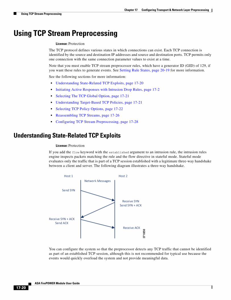
Understanding State-Related TCP ExploitsLicense: Protection
If you add the flow keyword with the established argument to an intrusion rule, the intrusion rules engine inspects packets matching the rule and the flow directive in stateful mode. Stateful mode evaluates only the traffic that is part of a TCP session established with a legitimate three-way handshake between a client and server. The following diagram illustrates a three-way handshake.
You can configure the system so that the preprocessor detects any TCP traffic that cannot be identified as part of an established TCP session, although this is not recommended for typical use because the events would quickly overload the system and not provide meaningful data.
17-20ASA FirePOWER Module User Guide

Chapter 17 Configuring Transport & Network Layer Preprocessing Using TCP Stream Preprocessing
Attacks like stick and snot use the system’s extensive rule sets and packet inspection against itself. These tools generate packets based on the patterns in Snort-based intrusion rules, and send them across the network. If your rules do not include the flow or flowbits keyword to configure them for stateful inspection, each packet will trigger the rule, overwhelming the system. Stateful inspection allows you to ignore these packets because they are not part of an established TCP session and do not provide meaningful information. When performing stateful inspection, the rules engine detects only those attacks that are part of an established TCP session, allowing analysts to focus on these rather than the volume of events caused by stick or snot.
Selecting The TCP Global OptionLicense: Protection
The TCP stream preprocessor has one global option that controls how the TCP stream preprocessor functions.
No preprocessor rules are associated with this option.
Packet Type Performance Boost
Enables ignoring TCP traffic for all ports and application protocols that are not specified in enabled intrusion rules, except when a TCP rule with both the source and destination ports set to any has a flow or flowbits option. This performance improvement could result in missed attacks.
Understanding Target-Based TCP PoliciesLicense: Protection
Different operating systems implement TCP in different ways. For example, Windows and some other operating systems require a TCP reset segment to have a precise TCP sequence number to reset a session, while Linux and other operating systems permit a range of sequence numbers. In this example, the stream preprocessor must understand exactly how the destination host will respond to the reset based on the sequence number. The stream preprocessor stops tracking the session only when the destination host considers the reset to be valid, so an attack cannot evade detection by sending packets after the preprocessor stops inspecting the stream. Other variations in TCP implementations include such things as whether an operating system employs a TCP timestamp option and, if so, how it handles the timestamp, and whether an operating system accepts or ignores data in a SYN packet.
Different operating systems also reassemble overlapping TCP segments in different ways. Overlapping TCP segments could reflect normal retransmissions of unacknowledged TCP traffic. They could also represent an attempt by an attacker, aware of the operating system of one of your hosts, to evade detection and exploit that host by sending malicious content hidden in overlapping segments. However, you can configure the stream preprocessor to be aware of the operating systems running on your monitored network segment so it reassembles segments the same way the target host does, allowing it to identify the attack.
You can create one or more TCP policies to tailor TCP stream inspection and reassembly to the different operating systems on your monitored network segment. For each policy, you identify one of thirteen operating system policies. You bind each TCP policy to a specific IP address or address block using as many TCP policies as you need to identify any or all of the hosts using a different operating system. The default TCP policy applies to any hosts on the monitored network that you do not identify in any other TCP policy, so there is no need to specify an IP address, CIDR block, or prefix length for the default TCP policy.
17-21ASA FirePOWER Module User Guide
Chapter 17 Configuring Transport & Network Layer Preprocessing Using TCP Stream Preprocessing
Note that you can also use adaptive profiles to dynamically select target-based policies for the TCP stream preprocessor using host operating system information for the target host in a packet. For more information, see Tuning Preprocessing in Passive Deployments, page 18-1.
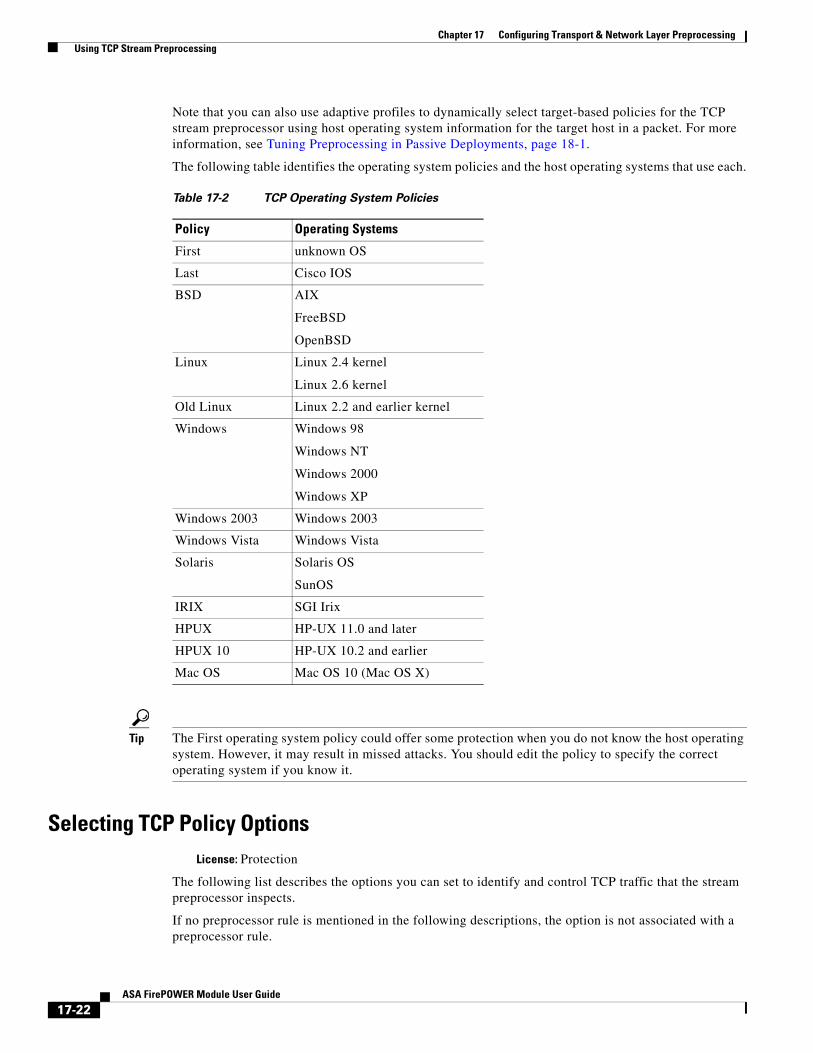
The following table identifies the operating system policies and the host operating systems that use each.
Tip The First operating system policy could offer some protection when you do not know the host operating system. However, it may result in missed attacks. You should edit the policy to specify the correct operating system if you know it.
Selecting TCP Policy OptionsLicense: Protection
The following list describes the options you can set to identify and control TCP traffic that the stream preprocessor inspects.
If no preprocessor rule is mentioned in the following descriptions, the option is not associated with a preprocessor rule.
Table 17-2 TCP Operating System Policies
Policy Operating Systems
First unknown OS
Last Cisco IOS
BSD AIX
FreeBSD
OpenBSD
Linux Linux 2.4 kernel
Linux 2.6 kernel
Old Linux Linux 2.2 and earlier kernel
Windows Windows 98
Windows NT
Windows 2000
Windows XP
Windows 2003 Windows 2003
Windows Vista Windows Vista
Solaris Solaris OS
SunOS
IRIX SGI Irix
HPUX HP-UX 11.0 and later
HPUX 10 HP-UX 10.2 and earlier
Mac OS Mac OS 10 (Mac OS X)
17-22ASA FirePOWER Module User Guide

Chapter 17 Configuring Transport & Network Layer Preprocessing Using TCP Stream Preprocessing
Network
Specifies the host IP addresses to which you want to apply the TCP stream reassembly policy.
You can specify a single IP address or address block. You can specify up to 255 total profiles including the default policy. For information on using IPv4 and IPv6 address blocks in the ASA FirePOWER module, see IP Address Conventions, page 1-4.
Note that the default setting in the default policy specifies all IP addresses on your monitored network segment that are not covered by another target-based policy. Therefore, you cannot and do not need to specify an IP address or CIDR block/prefix length for the default policy, and you cannot leave this setting blank in another policy or use address notation to represent any (for example, 0.0.0.0/0 or ::/0).
Note also that for a target-based policy to process traffic, the networks you identify must match or be a subset of the networks, and zones handled by the network analysis policy where you configure the target-based policy. See Customizing Preprocessing with Network Analysis Policies, page 13-2 for more information.
Policy
Identifies the TCP policy operating system of the target host or hosts. If you select a policy other than Mac OS, the system removes the data from the synchronization (SYN) packets and disables event generation for rule 129:2.
For more information, see Understanding Target-Based TCP Policies, page 17-21.
Timeout
The number of seconds between 1 and 86400 the intrusion rules engine keeps an inactive stream in the state table. If the stream is not reassembled in the specified time, the intrusion rules engine deletes it from the state table.
Note If your device is deployed on a segment where the network traffic is likely to reach the device’s bandwidth limits, you should consider setting this value higher (for example, to 600 seconds) to lower the amount of processing overhead.
Maximum TCP Window
Specifies the maximum TCP window size between 1 and 1073725440 bytes allowed as specified by a receiving host. Setting the value to 0 disables checking for the TCP window size.
Caution The upper limit is the maximum window size permitted by RFC, and is intended to prevent an attacker from evading detection, but setting a significantly large maximum window size could result in a self-imposed denial of service.
You can enable rule 129:6 to generate events for this option. See Setting Rule States, page 20-19 for more information.
Overlap Limit
Specifies that when the configured number between 0 (unlimited) and 255 of overlapping segments in a session has been detected, segment reassembly stops for that session and, if Stateful Inspection Anomalies is enabled and the accompanying preprocessor rule is enabled, an event is generated.
You can enable rule 129:7 to generate events for this option. See Setting Rule States, page 20-19 for more information.
17-23ASA FirePOWER Module User Guide

Chapter 17 Configuring Transport & Network Layer Preprocessing Using TCP Stream Preprocessing
Flush Factor
In an inline deployment, specifies that when a segment of decreased size has been detected subsequent to the configured number between 1 and 2048 of segments of non-decreasing size, the system flushes segment data accumulated for detection. Setting the value to 0 disables detection of this segment pattern, which can indicate the end of a request or response. Note that the Inline Normalization Normalize TCP Payload option must be enabled for this option the be effective. See Normalizing Inline Traffic, page 17-6 for more information.
Stateful Inspection Anomalies
Detects anomalous behavior in the TCP stack. When accompanying preprocessor rules are enabled, this may generate many events if TCP/IP stacks are poorly written.
You can enable the following rules to generate events for this option:
– 129:1 through 129:5
– 129:6 (Mac OS only)
– 129:8 through 129:11
– 129:13 through 129:19
See Setting Rule States, page 20-19 for more information:
TCP Session Hijacking
Detects TCP session hijacking by validating the hardware (MAC) addresses detected from both sides of a TCP connection during the 3-way handshake against subsequent packets received on the session. When the MAC address for one side or the other does not match, if Stateful Inspection Anomalies is enabled and one of the two corresponding preprocessor rules are enabled, the system generates events.
You can enable rules 129:9 and 129:10 to generate events for this option. See Setting Rule States, page 20-19 for more information.
Consecutive Small Segments
When Stateful Inspection Anomalies is enabled, specifies a maximum number of 1 to 2048 consecutive small TCP segments allowed. Setting the value to 0 disables checking for consecutive small segments.
You must set this option together with the Small Segment Size option, either disabling both or setting a non-zero value for both. Note that receiving as many as 2000 consecutive segments, even if each segment was 1 byte in length, without an intervening ACK would be far more consecutive segments than you would normally expect.
You can enable rule 129:12 to generate events for this option. See Setting Rule States, page 20-19 for more information.
Small Segment Size
When Stateful Inspection Anomalies is enabled, specifies the 1 to 2048 byte TCP segment size that is considered small. Setting the value to 0 disables specifying the size of a small segment.
You must set this option together with the Consecutive Small Segments option, either disabling both or setting a non-zero value for both. Note that a 2048 byte TCP segment is larger than a normal 1500 byte Ethernet frame.
17-24ASA FirePOWER Module User Guide

Chapter 17 Configuring Transport & Network Layer Preprocessing Using TCP Stream Preprocessing
Ports Ignoring Small Segments
When Stateful Inspection Anomalies, Consecutive Small Segments, and Small Segment Size are enabled, optionally specifies a comma-separated list of one or more ports that ignore small TCP segment detection. Leaving this option blank specifies that no ports are ignored.
You can add any port to the list, but the list only affects ports specified in one of the Perform Stream Reassembly on port lists in the TCP policy.
Require TCP 3-Way Handshake
Specifies that sessions are treated as established only upon completion of a TCP three-way handshake. Disable this option to increase performance, protect from SYN flood attacks, and permit operation in a partially asynchronous environment. Enable it to avoid attacks that attempt to generate false positives by sending information that is not part of an established TCP session.
You can enable rule 129:20 to generate events for this option. See Setting Rule States, page 20-19 for more information.
3-Way Handshake Timeout
Specifies the number of seconds between 0 (unlimited) and 86400 (twenty-four hours) by which a handshake must be completed when Require TCP 3-Way Handshake is enabled. You must enable Require TCP 3-Way Handshake to modify the value for this option.
Packet Size Performance Boost
Sets the preprocessor to not queue large packets in the reassembly buffer. This performance improvement could result in missed attacks. Disable this option to protect against evasion attempts using small packets of one to twenty bytes. Enable it when you are assured of no such attacks because all traffic is comprised of very large packets.
Legacy Reassembly
Sets the stream preprocessor to emulate the deprecated Stream 4 preprocessor when reassembling packets, which lets you compare events reassembled by the stream preprocessor to events based on the same data stream reassembled by the Stream 4 preprocessor.
Asynchronous Network
Specifies whether the monitored network is an asynchronous network, that is, a network where the system sees only half the traffic. When this option is enabled, the system does not reassemble TCP streams to increase performance.
Perform Stream Reassembly on Client Ports, Server Ports, Both Ports
Specifies for client ports, server ports, or both, a comma-separated list of ports to identify the traffic for the stream preprocessor to reassemble. See Selecting Stream Reassembly Options, page 17-26.
Perform Stream Reassembly on Client Services, Server Services, Both Services
Specifies for client services, server services, or both, services to identify in the traffic for the stream preprocessor to reassemble. See Selecting Stream Reassembly Options, page 17-26.
Troubleshooting Options: Maximum Queued Bytes
Support might ask you during a troubleshooting call to specify the amount of data that can be queued on one side of a TCP connection. A value of 0 specifies an unlimited number of bytes.
17-25ASA FirePOWER Module User Guide

Chapter 17 Configuring Transport & Network Layer Preprocessing Using TCP Stream Preprocessing
Caution Changing the setting for this troubleshooting option will affect performance and should be done only with Support guidance.
Troubleshooting Options: Maximum Queued Segments
Support might ask you during a troubleshooting call to specify the maximum number of bytes of data segments that can be queued on one side of a TCP connection. A value of 0 specifies an unlimited number of data segment bytes.
Caution Changing the setting for this troubleshooting option will affect performance and should be done only with Support guidance.
Reassembling TCP StreamsLicense: Protection
The stream preprocessor collects and reassembles all the packets that are part of a TCP session’s server-to-client communication stream, client-to-server communication stream, or both. This allows the rules engine to inspect the stream as a single, reassembled entity rather than inspecting only the individual packets that are part of a given stream.
See the following sections for more information:
• Understanding Stream-Based Attacks, page 17-26
• Selecting Stream Reassembly Options, page 17-26
Understanding Stream-Based Attacks
License: Protection
Stream reassembly allows the rules engine to identify stream-based attacks, which it may not detect when inspecting individual packets. You can specify which communication streams the rules engine reassembles based on your network needs. For example, when monitoring traffic on your web servers, you may only want to inspect client traffic because you are much less likely to receive malicious traffic from your own web server.
Selecting Stream Reassembly Options
License: Protection
In each TCP policy, you can specify a comma-separated list of ports to identify the traffic for the stream preprocessor to reassemble. If adaptive profiles are enabled, you can also list services that identify traffic to reassemble, either as an alternative to ports or in combination with ports. See Tuning Preprocessing in Passive Deployments, page 18-1 for information on enabling and using adaptive profiles.
You can specify ports, services, or both. You can specify separate lists of ports for any combination of client ports, server ports, and both. You can also specify separate lists of services for any combination of client services, server services, and both. For example, assume that you wanted to reassemble the following:
• SMTP (port 25) traffic from the client
17-26ASA FirePOWER Module User Guide

Chapter 17 Configuring Transport & Network Layer Preprocessing Using TCP Stream Preprocessing
• FTP server responses (port 21)
• telnet (port 23) traffic in both directions
You could configure the following:
• For client ports, specify 23, 25
• For server ports, specify 21, 23
Or, instead, you could configure the following:
• For client ports, specify 25
• For server ports, specify 21
• For both ports, specify 23
Additionally, consider the following example which combines ports and services and would be valid when adaptive profiles are enabled:
• For client ports, specify 23
• For client services, specify smtp
• For server ports, specify 21
• For server services, specify telnet
Although you can also specify all as the argument to provide reassembly for all ports, Cisco does not recommend setting ports to all because it may increase the amount of traffic inspected by this preprocessor and slow performance unnecessarily.
TCP reassembly automatically and transparently includes ports that you add to other preprocessors. However, if you do explicitly add ports to TCP reassembly lists that you have added to other preprocessor configurations, these additional ports are handled normally. This includes port lists for the following preprocessors:
• FTP/Telnet (server-level FTP)
• DCE/RPC
• HTTP Inspect
• SMTP
• Session Initiation Protocol
• POP
• IMAP
• SSL
Negating a port (for example, !77) can improve performance by preventing the TCP stream preprocessor from processing traffic for that port.
Note that reassembling additional traffic types (client, server, both) increases resource demands.
If no preprocessor rule is mentioned in the following descriptions, the option is not associated with a preprocessor rule.
Perform Stream Reassembly on Client Ports
Enables stream reassembly based on ports for the client side of the connection. In other words, it reassembles streams destined for web servers, mail servers, or other IP addresses typically defined by the IP addresses specified in $HOME_NET. Use this option when you expect malicious traffic to originate from clients.
17-27ASA FirePOWER Module User Guide

Chapter 17 Configuring Transport & Network Layer Preprocessing Using TCP Stream Preprocessing
Perform Stream Reassembly on Client Services
Enables stream reassembly based on services for the client side of the connection. Use this option when you expect malicious traffic to originate from clients.
This feature requires Protection and Control licenses.
Perform Stream Reassembly on Server Ports
Enables stream reassembly based on ports for the server side of the connection only. In other words, it reassembles streams originating from web servers, mail servers, or other IP addresses typically defined by the IP addresses specified in $EXTERNAL_NET. Use this option when you want to watch for server side attacks. You can disable this option by not specifying ports.
Perform Stream Reassembly on Server Services
Enables stream reassembly based on services for the server side of the connection only. Use this option when you want to watch for server side attacks. You can disable this option by not specifying services.
This feature requires Protection and Control licenses.
Perform Stream Reassembly on Both Ports
Enables stream reassembly based on ports for both the client and server side of the connection. Use this option when you expect that malicious traffic for the same ports may travel in either direction between clients and servers. You can disable this option by not specifying ports.
Perform Stream Reassembly on Both Services
Enables stream reassembly based on services for both the client and server side of the connection. Use this option when you expect that malicious traffic for the same services may travel in either direction between clients and servers.You can disable this option by not specifying services.
This feature requires Protection and Control licenses.
Configuring TCP Stream PreprocessingLicense: Protection
You can configure TCP stream preprocessing, including TCP policies. For more information on the TCP stream preprocessor configuration options, see Selecting TCP Policy Options, page 17-22.
To configure the stream preprocessor to track TCP sessions:
Step 1 Select Configuration > ASA FirePOWER Configuration > Policies > Access Control Policy.
The Access Control Policy page appears.
Step 2 Click the edit icon ( ) next to the access control policy you want to edit.
The access control policy editor appears.
Step 3 Select the Advanced tab.
The access control policy advanced settings page appears.
Step 4 Click the edit icon ( ) next to Network Analysis and Intrusion Policies.
The Network Analysis and Intrusion Policies pop-up window appears.
Step 5 Click Network Analysis Policy List.
17-28ASA FirePOWER Module User Guide

Chapter 17 Configuring Transport & Network Layer Preprocessing Using TCP Stream Preprocessing
The Network Analysis Policy List pop-up window appears.
Step 6 Click the edit icon ( ) next to the policy you want to edit.
If you have unsaved changes in another policy, click OK to discard those changes and continue. See Resolving Conflicts and Committing Policy Changes, page 11-15 for information on saving unsaved changes in another policy.
The Edit Policy page appears.
Step 7 Click Settings in the navigation panel on the left.
The Settings page appears.
Step 8 You have two choices, depending on whether TCP Stream Configuration under Transport/Network Layer Preprocessors is enabled:
• If the configuration is enabled, click Edit.
• If the configuration is disabled, click Enabled, then click Edit.
The TCP Stream Configuration page appears. A message at the bottom of the page identifies the policy layer that contains the configuration. See Using Layers in a Network Analysis or Intrusion Policy, page 12-1 for more information.
Step 9 Optionally, modify Packet Type Performance Boost under Global Settings. See Selecting The TCP Global Option, page 17-21 for more information.
Step 10 You have two options:
• Add a new target-based policy. Click the add icon ( ) next to Hosts on the left side of the page. The Add Target pop-up window appears. Specify one or more IP addresses in the Host Address field and click OK.
You can specify a single IP address or address block. You can create a total of 255 target-based policies including the default policy. For information on using IP address blocks in the ASA FirePOWER module, see IP Address Conventions, page 1-4.
Note that for a target-based policy to process traffic, the networks you identify must match or be a subset of the networks, and zones handled by the network analysis policy where you configure the target-based policy. See Customizing Preprocessing with Network Analysis Policies, page 13-2 for more information.
A new entry appears in the list of targets on the left side of the page, highlighted to indicate that it is selected, and the Configuration section updates to reflect the current configuration for the policy you added.
• Modify the settings for an existing target-based policy. Click the configured address for a policy you have added under Hosts on the left side of the page, or click default.
Your selection is highlighted and the Configuration section updates to display the current configuration for the policy you selected. To delete an existing target-based policy, click the delete icon ( ) next to the policy you want to remove.
Step 11 Optionally, modify any of the TCP policy options under Configuration.
For specific instructions on modifying settings for stream reassembly based on client services, server services, or both go to step 12; otherwise, go to step 15.
For more information, see Selecting TCP Policy Options, page 17-22, and Selecting Stream Reassembly Options, page 17-26.
Step 12 To modify settings for stream reassembly based on client, server, or both services, click inside the field you want to modify or click Edit next to the field.
The pop-up window for the field you selected appears.
17-29ASA FirePOWER Module User Guide
Chapter 17 Configuring Transport & Network Layer Preprocessing Using TCP Stream Preprocessing
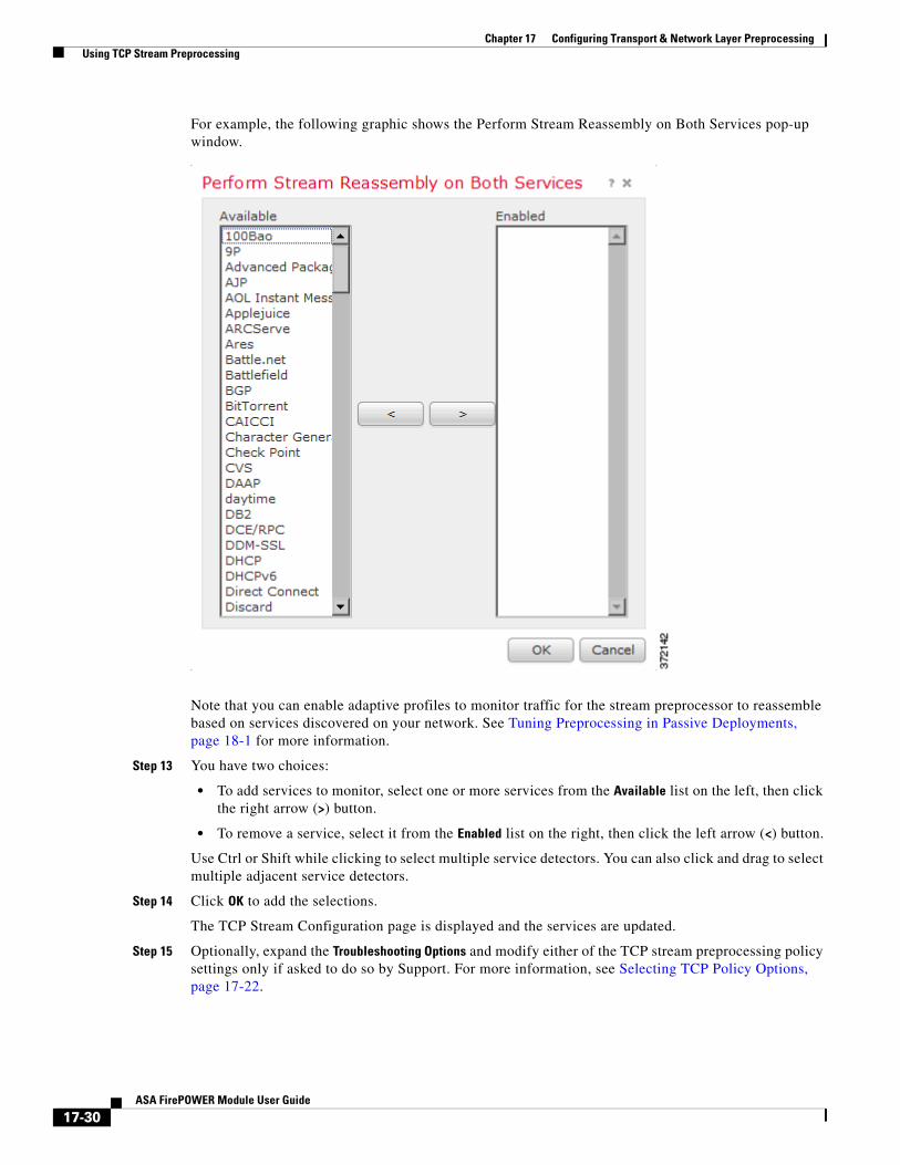
For example, the following graphic shows the Perform Stream Reassembly on Both Services pop-up window.
Note that you can enable adaptive profiles to monitor traffic for the stream preprocessor to reassemble based on services discovered on your network. See Tuning Preprocessing in Passive Deployments, page 18-1 for more information.
Step 13 You have two choices:
• To add services to monitor, select one or more services from the Available list on the left, then click the right arrow (>) button.
• To remove a service, select it from the Enabled list on the right, then click the left arrow (<) button.
Use Ctrl or Shift while clicking to select multiple service detectors. You can also click and drag to select multiple adjacent service detectors.
Step 14 Click OK to add the selections.
The TCP Stream Configuration page is displayed and the services are updated.
Step 15 Optionally, expand the Troubleshooting Options and modify either of the TCP stream preprocessing policy settings only if asked to do so by Support. For more information, see Selecting TCP Policy Options, page 17-22.
17-30ASA FirePOWER Module User Guide
Chapter 17 Configuring Transport & Network Layer Preprocessing Using UDP Stream Preprocessing
Step 16 Save your policy, continue editing, discard your changes, revert to the default configuration settings in the base policy, or exit while leaving your changes in the system cache. See Resolving Conflicts and Committing Policy Changes, page 11-15 for more information.
Using UDP Stream PreprocessingLicense: Protection
UDP stream preprocessing occurs when the rules engine processes packets against a UDP rule that includes the flow keyword (see Applying Rules to a TCP or UDP Client or Server Flow, page 23-50) using any of the following arguments:
• Established
• To Client
• From Client
• To Server
• From Server
UDP is a connectionless protocol that does not provide a means for two endpoints to establish a communication channel, exchange data, and close the channel. UDP data streams are not typically thought of in terms of sessions. However, the stream preprocessor uses the source and destination IP address fields in the encapsulating IP datagram header and the port fields in the UDP header to determine the direction of flow and identify a session. A session ends when a configurable timer is exceeded, or when either endpoint receives an ICMP message that the other endpoint is unreachable or the requested service is unavailable.
Note that the system does not generate events related to UDP stream preprocessing; however, you can enable related packet decoder rules to detect UDP protocol header anomalies. For information on events generated by the packet decoder, see Understanding Packet Decoding, page 17-16.
Configuring UDP Stream PreprocessingLicense: Protection
You can configure UDP stream preprocessing.
To configure the stream preprocessor to track UDP sessions:
Step 1 Select Configuration > ASA FirePOWER Configuration > Policies > Access Control Policy.
The Access Control Policy page appears.
Step 2 Click the edit icon ( ) next to the access control policy you want to edit.
The access control policy editor appears.
Step 3 Select the Advanced tab.
The access control policy advanced settings page appears.
Step 4 Click the edit icon ( ) next to Network Analysis and Intrusion Policies.
The Network Analysis and Intrusion Policies pop-up window appears.
Step 5 Click Network Analysis Policy List.
17-31ASA FirePOWER Module User Guide

Chapter 17 Configuring Transport & Network Layer Preprocessing Using UDP Stream Preprocessing
The Network Analysis Policy List pop-up window appears.
Step 6 Click the edit icon ( ) next to the policy you want to edit.
If you have unsaved changes in another policy, click OK to discard those changes and continue. See Resolving Conflicts and Committing Policy Changes, page 11-15 for information on saving unsaved changes in another policy.
The Edit Policy page appears.
Step 7 Click Settings in the navigation panel on the left.
The Settings page appears.
Step 8 You have two choices, depending on whether UDP Stream Configuration under Transport/Network Layer Preprocessors is enabled:
• If the configuration is enabled, click Edit.
• If the configuration is disabled, click Enabled, then click Edit.
The UDP Stream Configuration page appears. A message at the bottom of the page identifies the policy layer that contains the configuration. See Using Layers in a Network Analysis or Intrusion Policy, page 12-1 for more information.
Step 9 Optionally, configure a Timeout value to specify the number of seconds between 1 and 86400 the preprocessor keeps an inactive stream in the state table. If additional datagrams are not seen in the specified time, the preprocessor deletes the stream from the state table.
Step 10 Optionally, select Packet Type Performance Boost to ignore UDP traffic for all ports and application protocols that are not specified in enabled rules, except when a UDP rule with both the source and destination ports set to any has a flow or flowbits option. This performance improvement could result in missed attacks.
Step 11 Save your policy, continue editing, discard your changes, revert to the default configuration settings in the base policy, or exit while leaving your changes in the system cache. See Resolving Conflicts and Committing Policy Changes, page 11-15 for more information.
17-32ASA FirePOWER Module User Guide

Chapter 17 Configuring Transport & Network Layer Preprocessing Using UDP Stream Preprocessing
17-33ASA FirePOWER Module User Guide

Chapter 17 Configuring Transport & Network Layer Preprocessing Using UDP Stream Preprocessing
17-34ASA FirePOWER Module User Guide