Embed Size (px)
Citation preview

Configuring Resource Pool Management
This chapter describes the Cisco Resource Pool Management (RPM) feature. It includes the following main sections:
• RPM Overview
• How to Configure RPM
• Verifying RPM Components
• Troubleshooting RPM
• Configuration Examples for RPM
To identify the hardware platform or software image information associated with a feature, use the Feature Navigator on Cisco.com to search for information about the feature, or refer to the software release notes for a specific release. For more information, see the “Identifying Supported Platforms” section in the “Using Cisco IOS Software” chapter.
For a complete description of the commands mentioned in this chapter, refer to the Cisco IOS Dial Technologies Command Reference, Release 12.2. To locate documentation of other commands that appear in this chapter, use the command reference master index or search online.
RPM OverviewCisco RPM enables telephone companies and Internet service providers (ISPs) to share dial resources for wholesale and retail dial network services. With RPM, telcos and ISPs can count, control, and manage dial resources and provide accounting for shared resources when implementing different service-level agreements.
You can configure RPM in a single, standalone Cisco network access server (NAS) by using RPM or, optionally, across multiple NAS stacks by using one or more external Cisco Resource Pool Manager Servers (RPMS).
Cisco RPM gives data network service providers the capability to do the following:
• Have the flexibility to include local retail dial services in the same NAS with the wholesale dial customers.
• Manage customer use of shared resources such as modems or High-Level Data Link Control (HDLC) controllers for data calls.
Americas Headquarters:Cisco Systems, Inc., 170 West Tasman Drive, San Jose, CA 95134-1706 USA

Configuring Resource Pool Management RPM Overview
• Offer advanced wholesale dialup services using a Virtual Private Dialup Network (VPDN) to enterprise accounts and ISPs.
• Deploy Data over Voice Bearer Service (DoVBS).
• Manage call sessions by differentiating dial customers through customer profiles. The customer profile determines where resources are allocated and is based on the incoming Dialed Number Information Service (DNIS) number or Calling Line Identification (CLID).
• Efficiently use resource groups such as modems to offer differing over subscription rates and dial service-level agreements.
Note Ear and Mouth Feature Group B (E&M-FGB) is the only signaling type supported for channel-associated signaling (CAS) on T1 and T3 facilities; R2 is supported for E1 facilities. FG D is not supported. Cisco IOS software collects DNIS digits for the signaling types FGB, PRI, and SS7 and only E&M-FGB and R2 CAS customer profiles are supported. For all other CAS signaling types, use the default DNIS group customer profiles.
Components of Incoming and Outgoing Call ManagementCisco RPM manages both incoming calls and outgoing sessions. Cisco RPM differentiates dial customers through configured customer profiles based on the DNIS and call type determined at the time of an incoming call.
The components of incoming call management in the Cisco RPM are described in the following sections:
• Customer Profile Types
• DNIS Groups
• Call Types
• Resource Groups
• Resource Services
You can use Cisco RPM to answer all calls and differentiate customers by using VPDN profiles and groups. The components of outgoing session management in the Cisco RPM are described in the following sections:
• VPDN Groups
• VPDN Profiles
Note These components of Cisco RPM are enabled after the NAS and other equipment has been initially set up, configured, and verified for proper operation of the dial, PPP, VPDN, and authentication, authorization, and accounting (AAA) segments. Refer to the Cisco IOS documentation for these other segments for installation, configuration, and troubleshooting information before attempting to use RPM.
Configured DNIS groups and resource data can be associated to customer profiles. These customer profiles are selected by the incoming call DNIS number and call type and then used to identify resource allocations based on the associated resource groups and defined resource services.
2

Configuring Resource Pool Management RPM Overview
After the call is answered, customer profiles can also be associated with VPDN groups so the configured VPDN sessions and other data necessary to set up or reject a VPDN session are applied to the answered calls. VPDN group data includes associated domain name or DNIS, IP addresses of endpoints, maximum sessions per endpoint, maximum Multilink PPP (MLP) bundles per VPDN group, maximum links per MLP bundle, and other tunnel information.
Customer Profile Types
There are three types of customer profiles in Cisco RPM, which are described in the following sections:
• Customer Profiles
• Default Customer Profiles
• Backup Customer Profiles
Additionally, you can create a customer profile template and associate it with a customer profile; it is then integrated into the customer profile.
Customer Profiles
A customer profile defines how and when to answer a call. Customer profiles include the following components (see Figure 1):
• Customer profile name and description—Name and description of the customer.
• Session limits—Maximum number of standard sessions.
• Overflow limits—Maximum number of overflow sessions.
• DNIS groups.
• CLID.
• Resource groups.
• Resource services.
• VPDN groups and VPDN profiles.
• Call treatment—Determines how calls that exceed the session and overflow limits are treated.
Figure 1 Components of a Customer Profile
2852
3
Incomingcall management
Accept call
Outgoingsession management
• Customer profile name
• If no matches occur, session is sent to local authentication
• Session limits
• Overflow limits
• DNIS groups
• Resource groups
• Resource services
• VPDN profile or group
• Direct remote servicesor
or
3

Configuring Resource Pool Management RPM Overview
The incoming side of the customer profile determines if the call will be answered using parameters such as DNIS and call type from the assigned DNIS group and session limits. The call is then assigned the appropriate resource within the resource group defined in the customer profile. Each configured customer profile includes a maximum allowed session value and an overflow value. As sessions are started and ended, session counters are incremented and decremented so customer status is kept current. This information is used to monitor the customer resource limit and determine the appropriate call treatment based on the configured session limits.
The outgoing side of the customer profile directs the answered call to the appropriate destination:
Note Effective with Cisco Release 12.4(11)T, the L2F protocol was removed in Cisco IOS software.
• To a local AAA server of retail dial applications and Internet/intranet access.
• To a tunnel that is established between the NAS or L2TP Access Concentrator (LAC) to a wholesale VPDN home gateway of a dial customer, or L2TP Network Server (LNS) using Layer 2 Forwarding Protocol (L2F) or Layer 2 Tunneling Protocol (L2TP) technology.
Default Customer Profiles
Default customer profiles are identical to standard customer profiles, except that they do not have any associated DNIS groups. Default customer profiles are created using the reserved keyword default for the DNIS group.
Default customer profiles are used to provide session counting and resource assignment to incoming calls that do not match any of the configured DNIS groups. Although specific resources and DNIS groups can be assigned to customer profiles, default customer profiles allow resource pooling for the calls that do not match the configured DNIS groups or where the DNIS is not provided. Retail dial services and domain-based VPDN use default customer profiles.
When multiple default customer profiles are used, the call type (speech, digital, V.110, or V.120) of the default DNIS group is used to identify which default customer profile to use for an incoming call. At most, four default profiles (one for each call type) can be configured.
Note If default customer profiles are not defined, then calls that do not match a DNIS group in a customer profile are rejected with a “no answer” or “busy” call treatment sent to the switch.
Backup Customer Profiles
Backup customer profiles are customer profiles configured locally on the Cisco NAS and are used to answer calls based on a configured allocation scheme when the link between the Cisco NAS and Cisco RPMS is disabled. See the section “Configuring Customer Profiles Using Backup Customer Profiles” for more information about configuring backup customer profiles.
Customer Profile Template
With RPM, users can also implement wholesale dial services without using VPDN tunnels to complete dial-in calls to destinations of the end customer. This capability is accomplished with components of the AAA groups and the PPP configurations.
The AAA group provides IP addresses of AAA servers for authentication and accounting. The PPP configurations allow users to configure the Cisco IOS PPP feature set on each customer profile. In this current implementation, PPP configuration is based on the following:
4

Configuring Resource Pool Management RPM Overview
• Applicable IP address pool(s) or default local list of IP addresses
• Primary and secondary Domain Name System (DNS) or Windows Internet naming service (WINS)
• Number of links allowed for each call using MLP
Note The AAA and PPP integration applies to a single NAS environment.
To add PPP configurations to a customer profile, you must create a customer profile template. Once you create the template and associate it with a customer profile using the source template command, it is integrated into the customer profile.
The RPM customer profile template for the PPP command set, when used with the Cisco IOS feature, Server Groups Selected by DNIS, presents a strong single NAS solution for providers of wholesale dial services, as follows:
• Call acceptance is determined by the RPM before call answering, using the configured size limits and resource availability.
• The answered call then uses the PPP configuration defined in the template to initiate authentication, obtain an IP address, and select a DNS or WINS that is located at the customer site.
• The same DNIS that was used to choose the customer profile selects the servers for authentication/authorization and accounting that are located at the wholesale customer’s site.
The section “Configuring a Customer Profile Template” later in this chapter describes how to create a customer profile template so that you can configure the Cisco IOS PPP features on a customer profile, but this section does not list the existing PPP command set. For information about the PPP command set, refer to the Cisco IOS Dial Technologies Command Reference.
DNIS Groups
A DNIS group is a configured list of DNIS called party numbers that correspond to the numbers dialed to access particular customers, service offerings, or both. For example, if a customer from phone number 000-1234 calls a number 000-5678, the DNIS provides information on the number dialed—000-5678.
Cisco RPM checks the DNIS number of inbound calls against the configured DNIS groups, as follows:
• If Cisco RPM finds a match, it uses the configured information in the customer profile to which the DNIS group is assigned.
• If Cisco RPM does not find a match, it uses the configured information in the customer profile to which the default DNIS group is assigned.
• The DNIS/call type sequence can be associated only with one customer profile.
CLID Groups
A CLID group is a configured list of CLID calling party numbers. The CLID group specifies a list of numbers to reject if the group is associated with a call discriminator. For example, if a customer from phone number 000-1234 calls a number 000-5678, the CLID provides information on the calling party number—000-1234.
A CLID can be associated with only one CLID group.
5

Configuring Resource Pool Management RPM Overview
Call Types
Call types from calls originating from ISDN, SS7, and CAS (CT1, CT3, and CE1) are used to assign calls to the appropriate resource. Call types for ISDN and SS7 are based on Q.931 bearer capability. Call types for CAS are assigned based on static channel configuration.
Supported call types are as follows:
• Speech
• Digital
• V.110
• V.120
Note Voice over IP, fax over IP, and dial-out calls are not supported in RPM.
Resource Groups
Cisco RPM enables you to maximize the use of available shared resources within a Cisco NAS for various resource allocation schemes to support service-level agreements. Cisco RPM allows you to combine your Cisco NAS resource groups with call types (speech, digital, V.110, and V.120) and optional resource modem services. Resource groups and services are configured for customer profiles and assigned to incoming calls through DNIS groups and call types.
Resource groups have the following characteristics:
• Are configured on the Cisco NAS and applied to a customer profile.
• Represent groupings of similar hardware or firmware that are static and do not change on a per-call basis.
• Can define resources that are port-based or not port-based:
– Port-based resources are identified by physical location, such as a range of port/slot numbers (for example, modems or terminal adapters).
– Non-port-based resources are identified by a single size parameter (for example, HDLC framers or V.120 terminal adapters—V.120 terminal adapters are currently implemented as part of Cisco IOS software).
Resource assignments contain combinations of Cisco NAS resource groups, optional resource modem services, and call types. The NAS resources in resource groups that have not been assigned to a customer profile will not be used.
Note To support ISDN DoVBS, use a DNIS group and a configured customer profile to direct the speech call to the appropriate digital resource. The resource group assigned to this customer profile will be “digital resources” and also have a call type of “speech,” so the call will terminate on an HDLC controller rather than a modem.
Resource Services
A resource service contains a finite series of resource command strings that can be used to help dynamically configure an incoming connection. Services supported by a resource group are determined by the combination of hardware and firmware installed. Currently, resource service options can be
6

Configuring Resource Pool Management RPM Overview
configured and applied to resource groups. Resource services can be defined to affect minimum and maximum speed, modulation, error correction, and compression, as shown in Table 1.
VPDN Groups
The VPDN group contains the data required to build a VPDN tunnel from the RPM NAS LAC to the LNS. In the context of RPM, VPDN is authorized by first associating a customer profile with a VPDN group, and second by associating the VPDN group to the DNIS group used for that customer profile. VPDN group data includes the endpoint IP addresses.
Cisco RPM enables you to specify multiple IP endpoints for a VPDN group, as follows:
• If two or more IP endpoints are specified, Cisco RPM uses a load-balancing method to ensure that traffic is distributed across the IP endpoints.
• For DNIS-based VPDN dial service, VPDN groups are assigned to customer profiles based on the incoming DNIS number and the configured DNIS groups.
• For domain-based VPDN dial service, VPDN groups are assigned to the customer profile or the default customer profile with the matching call-type assignment.
• For either DNIS-based or domain-based VPDN dial services, there is a customer profile or default customer profile for the initial resource allocation and customer session limits.
The VPDN group provides call management by allowing limits to be applied to both the number of MLP bundles per tunnel and the number of links per MLP bundle. Limits can also restrict the number of sessions per IP endpoint. If you require more granular control of VPDN counters, use VPDN profiles.
VPDN Profiles
VPDN profiles allow session and overflow limits to be imposed for a particular customer profile. These limits are unrelated to the limits imposed by the customer profile. A customer profile is associated with a VPDN profile. A VPDN profile is associated with a VPDN group. VPDN profiles are required only when these additional counters are required for VPDN usage per customer profile.
Call TreatmentsCall treatment determines how calls are handled when certain events require the call to be rejected. For example, if the session and overflow limits for one of your customers have been exceeded, any additional calls will receive a busy signal (see Table 2).
Table 1 Resource Services
Service Options Comments
min-speed <300–56000>, any Must be a V.90 increment.
max-speed <300–56000>, any Must be a V.90 increment.
modulation k56flex, v22bis, v32bis, v34, v90, any
None.
error-correction 1apm, mn14 This is a hidden command.
compression mnps, v42bis This is a hidden command.
7

Configuring Resource Pool Management RPM Overview
Details on RPM Call ProcessesOn the incoming call management of the customer profile, the following sequence occurs to determine if a call is answered:
1. The incoming DNIS is mapped to a DNIS group; if there is no incoming DNIS number, or the DNIS number provided does not match any configured DNIS group, the DNIS group default is used.
2. The mapped DNIS group is checked against configured call discriminator profiles to confirm if this DNIS group/call-type combination is disallowed. If there is a match, the call is immediately rejected.
3. Once a DNIS group or a default DNIS group is identified, the customer profile associated with that DNIS group and the call type (from the bearer capability for ISDN call, statically configured for CAS calls) is selected. If there is no corresponding customer profile, the call is rejected.
4. The customer profile includes a session limit value and an overflow limit value. If these thresholds are not met, the call is then assigned the appropriate resource defined in the customer profile. If the thresholds are met, the call is rejected.
5. If resources are available from the resource group defined in the customer profile, the call is answered. Otherwise, the call is rejected.
Table 2 Call-Treatment Table
Event Call-Treatment Option Results
Customer profile not found
No answer (default) The caller receives rings until the switch eventually times out. Implies that the NAS was appropriate, but resources were unavailable. The caller should try later.
Busy The switch drops the call from the NAS and sends a busy signal back to the caller. The call is rejected based on not matching a DNIS group/call type and customer profile. Can be used to immediately reject the call and free up the circuit.
Customer profile limits exceeded
Busy The switch drops the call from the NAS and sends a busy signal back to the caller.
NAS resource not available
Channel not available (default)
The switch sends the call to the next channel in the trunk group. The call can be answered, but the NAS does not have any available resources in the resource groups. Allows the switch to try additional channels until it gets to a different NAS in the same trunk group that has the available resources.
Busy The switch drops the call from the NAS and sends a busy signal back to the caller. Can be used when the trunk group does not span additional NASes.
Call discrimination match No answer The caller receives rings until the switch eventually times out.
8

Configuring Resource Pool Management RPM Overview
6. As sessions start and end, the session counters increase and decrease, so the customer profile call counters are kept current.
See Figure 2 for a graphical illustration of the RPM call processes.
Figure 2 Incoming Call Management: RPM Functional Description
After the call is answered and if VPDN is enabled, Cisco RPM checks the customer profile for an assigned VPDN group or profile. The outgoing session management of the customer profile directs the answered call to the appropriate destination (see Figure 3), as follows:
Note Effective with Cisco Release 12.4(11)T, the L2F protocol was removed in Cisco IOS software.
• To a local AAA server of retail dial applications and Internet/intranet access.
• To a tunnel that is established between the NAS or LAC and a wholesale VPDN home gateway from a dial customer or LNS using L2F or L2TP tunneling technology.
Figure 3 Outgoing Call Management: RPM Functional Description for VPDN Profiles and
Groups
If a VPDN profile is found, the limits are checked, as follows:
• If the limits have not been exceeded, the VPDN group data associated with that VPDN profile is used to build a VPDN tunnel.
• If the VPDN limits have been exceeded, the call is disconnected.
Incomingcall DNIS
group/call type
Calldiscriminator
DNIS/call typeBase
Applyresourceservice
Accept call
Resourcegroup
Overflow
Virtual Range
Resourcegroup
Limit
2642
1
Physical
Customerprofile
VPDNenable
Customerprofile
VPDNprofileBase
= Optional
Overflow Bundles AcceptVPDN
VPDNgroup
Links
2642
0
9
Configuring Resource Pool Management RPM Overview
If a VPDN group is found within the customer profile, the VPDN group data is used to build a VPDN tunnel, as follows:
• If the VPDN group limits (number of multilink bundles, number of links per bundle) have not been exceeded, a VPDN tunnel is built.
• If the limits have been reached, the call is disconnected.
If no VPDN profile is assigned to the customer profile and VPDN is enabled, non-RPM VPDN service is attempted. If the attempt fails, the call is processed as a retail dial service call if local AAA service is available.
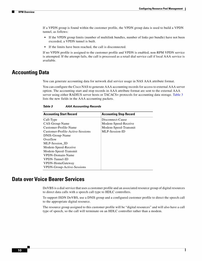
Accounting DataYou can generate accounting data for network dial service usage in NAS AAA attribute format.
You can configure the Cisco NAS to generate AAA accounting records for access to external AAA server option. The accounting start and stop records in AAA attribute format are sent to the external AAA server using either RADIUS server hosts or TACACS+ protocols for accounting data storage. Table 3 lists the new fields in the AAA accounting packets.
Data over Voice Bearer ServicesDoVBS is a dial service that uses a customer profile and an associated resource group of digital resources to direct data calls with a speech call type to HDLC controllers.
To support ISDN DoVBS, use a DNIS group and a configured customer profile to direct the speech call to the appropriate digital resource.
The resource group assigned to this customer profile will be “digital resources” and will also have a call type of speech, so the call will terminate on an HDLC controller rather than a modem.
Table 3 AAA Accounting Records
Accounting Start Record Accounting Stop Record
Call-TypeCAS-Group-NameCustomer-Profile-NameCustomer-Profile-Active-SessionsDNIS-Group-NameOverflowMLP-Session_IDModem-Speed-ReceiveModem-Speed-TransmitVPDN-Domain-NameVPDN-Tunnel-IDVPDN-HomeGatewayVPDN-Group-Active-Sessions
Disconnect-CauseModem-Speed-ReceiveModem-Speed-TransmitMLP-Session-ID
10

Configuring Resource Pool Management RPM Overview
Call Discriminator ProfilesThe Cisco RPM CLID/DNIS Call Discriminator feature lets you specify a list of calling party numbers to be rejected for inbound calls. This Cisco IOS Release 12.2 CLID/DNIS call screening feature expands previous call screening features in Cisco RPM. CLID/DNIS call screening provides an additional way to screen calls on the basis of CLID/DNIS for both local and remote RPM.
Cisco RPM CLID/DNIS Call Discriminator profiles enable you to process calls differently on the basis of the call type and CLID combination. Resource pool management offers a call discrimination feature that rejects calls on the basis of a CLID group and a call type filter. When a call arrives at the NAS, the CLID and the call type are matched against a table of disallowed calls. If the CLID and call type match entries in this table, the call is rejected before it is assigned Cisco NAS resources or before any other Cisco RPM processing occurs. This is called precall screening.
Precall screening decides whether the call is allowed to be processed. You can use the following types of discriminators to execute precall screening:
• ISDN discriminator—Accepts a call if the calling number matches a number in a group of configured numbers (ISDN group). This is also called white box screening. If you configure an ISDN group, only the calling numbers specified in the group are accepted.
• DNIS discriminator—Accepts a call if the called party number matches a number in a group of configured numbers (DNIS group). If you set up a DNIS group, only the called party numbers in the group are accepted. DNIS gives you information about the called party.
• Cisco RPM CLID/DNIS discriminator—Rejects a call if the calling number matches a number in a group of configured numbers (CLID/DNIS group). This is also called black box screening.
If you configure a discriminator with a CLID group, the calling party numbers specified in the group are rejected. CLID gives you information about the caller.
Similarly, if you configure a discriminator with a DNIS group, the called party numbers specified in the group are rejected.
The Cisco RPM CLID/DNIS Call Discriminator Feature is independent of ISDN or DNIS screening done by other subsystems. ISDN or DNIS screening and Cisco RPM CLID/DNIS screening can both be present in the same system. Both features are executed if configured. Similarly, if DNIS Preauthorization using AAA is configured, it is present in addition to Cisco RPM CLID/DNIS screening. Refer to the Cisco IOS Security Configuration Guide for more information about call preauthorization.
In Cisco RPM CLID/DNIS screening, the discriminator can be a CLID discriminator, a DNIS discriminator, or a discriminator that screens on both the CLID and DNIS. The resulting discrimination logic is:
• If a discriminator contains just DNIS groups, it is a DNIS discriminator that ignores CLID. The DNIS discriminator blocks the call if the called number is in a DNIS group, which the call type references.
• If a discriminator contains just CLID groups, it is a CLID discriminator that ignores DNIS. The CLID discriminator blocks the call if the calling number is in a CLID group, which the call type references.
• If a discriminator contains both CLID and DNIS groups, it is a logical AND discriminator. It blocks the call if the calling number and called number are in the CLID or DNIS group, and the call type references the corresponding discriminator.
Figure 4 shows how call discrimination can be used to restrict a specific DNIS group to only modem calls by creating call discrimination settings for the DNIS group and the other supported call types (digital, V.110, and V.120).
11

Configuring Resource Pool Management RPM Overview
Figure 4 Call Discrimination
Incoming Call PreauthenticationWith ISDN PRI or channel-associated signaling (CAS), information about an incoming call is available to the NAS before the call is connected. The available call information includes:
• The DNIS, also referred to as the called number
• The CLID, also referred to as the calling number
• The call type, also referred to as the bearer capability
The Preauthentication with ISDN PRI and Channel-Associated Signalling feature introduced in Cisco IOS Release 12.2 allows a Cisco NAS to decide—on the basis of the DNIS number, the CLID number, or the call type—whether to connect an incoming call.
When an incoming call arrives from the public network switch, but before it is connected, this feature enables the NAS to send the DNIS number, CLID number, and call type to a RADIUS server for authorization. If the server authorizes the call, the NAS accepts the call. If the server does not authorize the call, the NAS sends a disconnect message to the public network switch to reject the call.
The Preauthentication with ISDN PRI and Channel-Associated Signalling feature offers the following benefits:
• With ISDN PRI, it enables user authentication and authorization before a call is answered. With CAS, the call must be answered; however, the call can be dropped if preauthentication fails.
• It enables service providers to better manage ports using their existing RADIUS solutions.
• Coupled with a preauthentication RADIUS server application, it enables service providers to efficiently manage the use of shared resources to offer differing service-level agreements.
For more information about the Preauthentication with ISDN PRI and Channel-Associated Signalling feature, refer to the Cisco IOS Security Configuration Guide.
12

Configuring Resource Pool Management RPM Overview
RPM Standalone Network Access ServerA single NAS using Cisco RPM can provide the following:
• Wholesale VPDN dial service to corporate customers
• Direct remote services
• Retail dial service to end users
Figure 5 and Figure 6 show multiple connections to a Cisco AS5300 NAS. Incoming calls to the NAS can use ISDN PRI signaling, CAS, or the SS7 signaling protocol. Figure 5 shows incoming calls that are authenticated locally for retail dial services or forwarded through VPDN tunnels for wholesale dial services.
Note This implementation does not use Cisco RPM CLID/DNIS Call Discriminator Feature. If you are not using Cisco RPMS and you have more than one Cisco NAS, you must manually configure each NAS by using Cisco IOS commands. Resource usage information is not shared between NASes.
Figure 5 Retail Dial Service Using RPM
Figure 6 shows a method of implementing wholesale dial services without using VPDN tunnels by creating individual customer profiles that consist of AAA groups and PPP configurations. The AAA groups provide IP addresses of AAA servers for authentication and accounting. The PPP configurations enable you to set different PPP parameter values on each customer profile. A customer profile typically includes the following PPP parameters:
• Applicable IP address pools or a default local list of IP addresses
• Primary and secondary DNS or WINS
• Authentication method such as the Password Authentication Protocol (PAP), Challenge Handshake Authentication Protocol (CHAP), or Microsoft CHAP Version 1 (MS-CHAP)
• Number of links allowed for each call using Multilink PPP
Note The AAA and PPP integration applies to a single NAS environment; the external RPMS solution is not supported.
Modem
Remote user
Terminaladapter
Router
PSTN
PRICASSS7
Cisco AS5300(NAS)
Internet/intranet
1802
1
AAAserver
(Optional)
13

Configuring Resource Pool Management RPM Overview
Figure 6 Resource Pool Management with Direct Remote Services
Call Processing
For call processing, incoming calls are matched to a DNIS group and the customer profile associated with that DNIS group. If a match is found, the customer profile session and overflow limits are applied and if available, the required resources are allocated. If a DNIS group is not found, the customer profile associated with the default DNIS group is used. The call is rejected if a customer profile using the default DNIS group cannot be found.
After the call is answered and if VPDN is enabled, the Cisco RPM checks the customer profile for an assigned VPDN group or profile. If a VPDN group is found, Cisco RPM authorizes VPDN by matching the group domain name or DNIS with the incoming call. If a match is found, VPDN profile session and overflow limits are applied, and, if the limits are not exceeded, tunnel negotiation begins. If the VPDN limits are exceeded, the call is disconnected.
If no VPDN profile is assigned to the customer profile and VPDN is enabled, non-RPM VPDN service will be attempted. If it fails, the call is processed as a retail dial service call if local AAA service is available.
Base Session and Overflow Session Limits
Cisco RPM enables you to set base and overflow session limits in each customer profile. The base session limit determines the maximum number of nonoverflow sessions supported for a customer profile. When the session limit is reached, if overflow sessions are not enabled, any new calls are rejected. If overflow sessions are enabled, new sessions up to the session overflow limit are processed and marked as overflow for call handling and accounting.
The session overflow limit determines the allowable number of sessions above the session limit. If the session overflow limit is greater than zero, overflow sessions are enabled and the maximum number of allowed sessions is the session limit plus the session overflow limit. While the session overflow limit has
WANinfrastructure
Modem
Remote user
Terminaladapter
Router
PSTN
Optionallocal AAA
Cisco AS5300(NAS)
Customerprofiles
2830
7
Customer A
Customer B
AAADNS
AAADNS
DNIS
14
Configuring Resource Pool Management RPM Overview
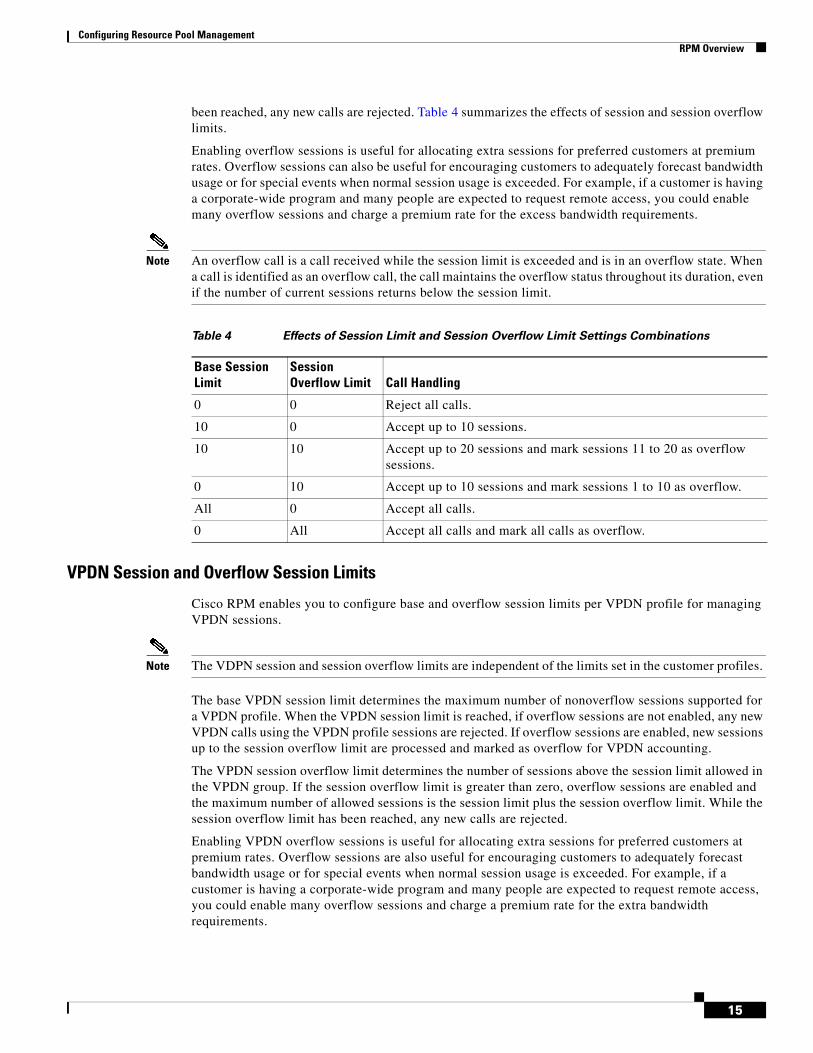
been reached, any new calls are rejected. Table 4 summarizes the effects of session and session overflow limits.
Enabling overflow sessions is useful for allocating extra sessions for preferred customers at premium rates. Overflow sessions can also be useful for encouraging customers to adequately forecast bandwidth usage or for special events when normal session usage is exceeded. For example, if a customer is having a corporate-wide program and many people are expected to request remote access, you could enable many overflow sessions and charge a premium rate for the excess bandwidth requirements.
Note An overflow call is a call received while the session limit is exceeded and is in an overflow state. When a call is identified as an overflow call, the call maintains the overflow status throughout its duration, even if the number of current sessions returns below the session limit.
VPDN Session and Overflow Session Limits
Cisco RPM enables you to configure base and overflow session limits per VPDN profile for managing VPDN sessions.
Note The VDPN session and session overflow limits are independent of the limits set in the customer profiles.
The base VPDN session limit determines the maximum number of nonoverflow sessions supported for a VPDN profile. When the VPDN session limit is reached, if overflow sessions are not enabled, any new VPDN calls using the VPDN profile sessions are rejected. If overflow sessions are enabled, new sessions up to the session overflow limit are processed and marked as overflow for VPDN accounting.
The VPDN session overflow limit determines the number of sessions above the session limit allowed in the VPDN group. If the session overflow limit is greater than zero, overflow sessions are enabled and the maximum number of allowed sessions is the session limit plus the session overflow limit. While the session overflow limit has been reached, any new calls are rejected.
Enabling VPDN overflow sessions is useful for allocating extra sessions for preferred customers at premium rates. Overflow sessions are also useful for encouraging customers to adequately forecast bandwidth usage or for special events when normal session usage is exceeded. For example, if a customer is having a corporate-wide program and many people are expected to request remote access, you could enable many overflow sessions and charge a premium rate for the extra bandwidth requirements.
Table 4 Effects of Session Limit and Session Overflow Limit Settings Combinations
Base Session Limit
Session Overflow Limit Call Handling
0 0 Reject all calls.
10 0 Accept up to 10 sessions.
10 10 Accept up to 20 sessions and mark sessions 11 to 20 as overflow sessions.
0 10 Accept up to 10 sessions and mark sessions 1 to 10 as overflow.
All 0 Accept all calls.
0 All Accept all calls and mark all calls as overflow.
15

Configuring Resource Pool Management RPM Overview
VPDN MLP Bundle and Links-per-Bundle Limits
To ensure that resources are not consumed by a few users with MLP connections, Cisco RPM also enables you to specify the maximum number of MLP bundles that can open in a VPDN group. In addition, you can specify the maximum number of links for each MLP bundle.
For example, if standard ISDN users access the VPDN profile, limit this setting to two links per bundle. If video conferencing is used, increase this setting to accommodate the necessary bandwidth (usually six links). These limits have no overflow option and are configured under the VPDN group component.
VPDN Tunnel Limits
For increased VPDN tunnel management, Cisco RPM enables you to set an IP endpoint session limit for each IP endpoint. IP endpoints are configured for VPDN groups.
Figure 7 and Figure 8 show logical flowcharts of RPM call processing for a standalone NAS with and without the RPM Direct Remote Services feature.
16

Configuring Resource Pool Management RPM Overview
Figure 7 RPM Call-Processing Flowchart for a Standalone Network Access Server
DNIS and call type Yes
Yes
Yes
Yes
Yes
No
No
No
No
No
No
Calldiscriminator
match
2260
9
Reject—Session limitcall treatment busy
Yes
Mapped DNIScustomer profile
exists
Has CPreached maximum
connections
Overflowconfigured andmaximum not
exceeded
Resourcesavailable
Defaultcustomer profile
match
Reject—No resourcecall treatment:
CNA (default) or busy
Rejectcall treatment:
No answer
Reject—No CPcall treatment:
No answer (default)or busy
Answer call CheckVPDN
17

Configuring Resource Pool Management RPM Overview
Figure 8 Flowchart for a Standalone Network Access Server with RPM Direct Remote Services
DNIS and call type Yes
Yes
Yes
Yes
Yes
No
No
No
No
No
Calldiscriminator
match
2958
4
Reject—Session limitcall treatment busy
Mapped DNIScustomer profile
exists
Has CPreached maximum
connections
Overflowconfigured andmaximum not
exceeded
Resourcesavailable
Reject—No resourcecall treatment:
CNA (default) or busy
Rejectcall treatment:
No answer
Reject—No CPcall treatment:
No answer (default)or busy
Answer callCheckPPP
Template
18

Configuring Resource Pool Management RPM Overview
RPM Using the Cisco RPMSFigure 9 shows a typical resource pooling network scenario using RPMS.
Figure 9 RPM Scenario Using RPMS
Resource Manager ProtocolResource Manager Protocol (RMP) is a robust, recoverable protocol used for communication between the Cisco RPMS and the NAS. Each NAS client uses RMP to communicate resource management requests to the Cisco RPMS server. RPMS also periodically polls the NAS clients to query their current call information or address error conditions when they occur. RMP also allows for protocol attributes that make it extensible and enable support for customer billing requirements.
Figure 10 shows the relationship of Cisco RPM CLID/DNIS Call Discriminator Feature and RMP.
Figure 10 Cisco RPM CLID/DNIS Call Discriminator Feature and RMP
Note RMP must be enabled on all NASes that communicate with the Cisco RPM CLID/DNIS Call Discriminator Feature.
Modem
Modem
Terminaladapter
Router
PSTN/ISDN
PRICT1CE1
UG group
VPDN tunnel
VPDN tunnel
L2F/L2TP
L2F/L2TP
1724
3
Customer A
Customer B
AAAserver
AAAserver
AAAproxyserver
(Optional)
Homegatewayrouter
Homegatewayrouter
CO
CO
Cisco RPMS
Internet/intranet
RMP protocol
RMP interface
Cisco RPMSNASwith RMP installed 1724
4
19

Configuring Resource Pool Management RPM Overview
Direct Remote ServicesDirect remote services is an enhancement to Cisco RPM implemented in Cisco IOS Release 12.0(7)T that enables service providers to implement wholesale dial services without using VPDN tunnels. A customer profile that has been preconfigured with a PPP template to define the unique PPP services for the wholesale dial customer is selected by the incoming DNIS and call type. At the same time, the DNIS is used to select AAA server groups for authentication/authorization and for accounting for the customer.
PPP Common Configuration Architecture (CCA) is the new component of the RPM customer profile that enables direct remote services. The full PPP command set available in Cisco IOS software is configurable per customer profile for wholesale dial applications. A customer profile typically includes the following PPP parameters:
• Local or named IP address pools
• Primary and secondary DNS or WINS addresses
• Authentication method (PAP, CHAP, MS-CHAP)
• Multilink PPP links per bundle limits
The AAA session information is selected by the incoming DNIS. AAA server lists provide the IP addresses of AAA servers for authentication, authorization, and accounting in the wholesale local network of the customer. The server lists for both authentication and authorization and for accounting contain the server addresses, AAA server type, timeout, retransmission, and keys per server.
When direct remote services is implemented on a Cisco NAS, the following sequence occurs:
1. The NAS sends an authorization request packet to the AAA server by using the authentication method (PAP, CHAP, MSCHAP) that has been configured through PPP.
2. The AAA server accepts the authorization request and returns one of the following items to the NAS:
– A specific IP address
– An IP address pool name
– Nothing
3. Depending on the response from the AAA server, the NAS assigns one of the following items to the user through the DNS/WINS:
– The IP address returned by the AAA server
– An IP address randomly assigned from the named IP address pool
– An IP address from a pool specified in the customer profile template
Note If the AAA server sends back to the NAS a named IP address pool and that name does not exist on the NAS, the request for service is denied. If the AAA server does not send anything back to the NAS and there is an IP address pool name configured in the customer profile template, an address from that pool is used for the session.
RPM Process with RPMS and SS7For information on SS7 implementation for RPM, refer to the document Cisco Resource Pool Manager Server 1.0 SS7 Implementation.
20

Configuring Resource Pool Management How to Configure RPM
Additional Information About Cisco RPMFor more information about Cisco RPM, see the following documents:
• AAA Server Group
• Cisco Access VPN Solutions Using Tunneling Technology
• Cisco AS5200 Universal Access Server Software Configuration Guide
• Cisco AS5300 Software Configuration Guide
• Cisco AS5800 Access Server Software ICG
• Cisco Resource Pool Manager Server Configuration Guide
• Cisco Resource Pool Manager Server Installation Guide
• Cisco Resource Pool Manager Server Solutions Guide
• Dial Solutions Quick Configuration Guide
• RADIUS Multiple UDP Ports Support
• Redundant Link Manager
• Release Notes for Cisco Resource Pool Manager Server Release 1.0
• Resource Pool Management
• Resource Pool Management with Direct Remote Services
• Resource Pool Manager Customer Profile Template
• Selecting AAA Server Groups Based on DNIS
• SS7 Continuity Testing for Network Access Servers
• SS7 Dial Solution System Integration
How to Configure RPMRead and comply with the following restrictions and prerequisites before beginning RPM configuration:
• RPM is supported on Cisco AS5300, Cisco AS5400, and Cisco AS5800 Universal Access Servers
• Modem pooling and RPM are not compatible.
• The Cisco RPM CLID/DNIS Call Discriminator Feature must have Cisco RPM configured.
• CLID screening is not available to channel-associated signaling (CAS) interrupt level calls.
• Cisco RPM requires the NPE 300 processor when implemented on the Cisco AS5800.
• For Cisco AS5200 and Cisco AS5300 access servers, Cisco IOS Release 12.0(4)XI1 or later releases must be running on the NAS.
• For Cisco AS5800, Cisco IOS Release 12.0(5)T or later releases must be running on the NAS.
• A minimum of 64 MB must be available on the DMM cards.
• The RPM application requires an NPE 300.
• For call discriminator profiles, the Cisco AS5300, Cisco AS5400, or Cisco AS5800 Universal Access Servers require a minimum of 16 MB Flash memory and 128 MB DRAM memory, and need to be configured for VoIP as an H.323-compliant gateway.
The following tasks must be performed before configuring RPM:
21
Configuring Resource Pool Management How to Configure RPM
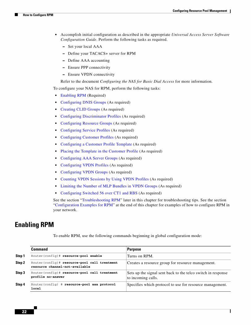
• Accomplish initial configuration as described in the appropriate Universal Access Server Software Configuration Guide. Perform the following tasks as required.
– Set your local AAA
– Define your TACACS+ server for RPM
– Define AAA accounting
– Ensure PPP connectivity
– Ensure VPDN connectivity
Refer to the document Configuring the NAS for Basic Dial Access for more information.
To configure your NAS for RPM, perform the following tasks:
• Enabling RPM (Required)
• Configuring DNIS Groups (As required)
• Creating CLID Groups (As required)
• Configuring Discriminator Profiles (As required)
• Configuring Resource Groups (As required)
• Configuring Service Profiles (As required)
• Configuring Customer Profiles (As required)
• Configuring a Customer Profile Template (As required)
• Placing the Template in the Customer Profile (As required)
• Configuring AAA Server Groups (As required)
• Configuring VPDN Profiles (As required)
• Configuring VPDN Groups (As required)
• Counting VPDN Sessions by Using VPDN Profiles (As required)
• Limiting the Number of MLP Bundles in VPDN Groups (As required)
• Configuring Switched 56 over CT1 and RBS (As required)
See the section “Troubleshooting RPM” later in this chapter for troubleshooting tips. See the section “Configuration Examples for RPM” at the end of this chapter for examples of how to configure RPM in your network.
Enabling RPMTo enable RPM, use the following commands beginning in global configuration mode:
Command Purpose
Step 1 Router(config)# resource-pool enable Turns on RPM.
Step 2 Router(config)# resource-pool call treatment resource channel-not-available
Creates a resource group for resource management.
Step 3 Router(config)# resource-pool call treatment profile no-answer
Sets up the signal sent back to the telco switch in response to incoming calls.
Step 4 Router(config) # resource-pool aaa protocol local
Specifies which protocol to use for resource management.
22

Configuring Resource Pool Management How to Configure RPM
Note If you have an RPMS, you need not define VPDN groups/profiles, customer profiles, or DNIS groups on the NAS; you need only define resource groups. Configure the remaining items by using the RPMS system.
Configuring DNIS GroupsThis configuration task is optional.
To configure DNIS groups, use the following commands beginning in global configuration mode:
For default DNIS service, no DNIS group configuration is required. The following characteristics and restrictions apply to DNIS group configuration:
• Each DNIS group/call-type combination can apply to only one customer profile.
• You can use up to four default DNIS groups (one for each call type).
• You must statically configure CAS call types.
• You can use x, X or . as wildcards within each DNIS number.
Creating CLID GroupsYou can add multiple CLID groups to a discriminator profile. You can organize CLID numbers for a customer or service type into a CLID group. Add all CLID numbers into one CLID group, or subdivide the CLID numbers using criteria such as call type, geographical location, or division. To create CLID groups, use the following commands beginning in global configuration mode:
Command Purpose
Step 1 Router(config)# dialer dnis group dnis-group-name
Creates a DNIS group. The name you specify in this step must match the name entered when configuring the customer profile.
Step 2 Router(config-called-group)# call-type cas {digital | speech}
Statically sets the call-type override for incoming CAS calls.
Step 3 Router(config-called-group)# number number Enters DNIS numbers to be used in the customer profile. (Wildcards can be used.)
23

Configuring Resource Pool Management How to Configure RPM
Configuring Discriminator ProfilesDiscriminator profiles enable you to process calls differently on the basis of the call type and CLID/DNIS combination. The “Call Discriminator Profiles” section earlier in this chapter describes the different types of discriminator profiles that you can create.
To configure discriminator profiles for RPM implementation, use the following commands beginning in global configuration mode:
Command Purpose
Step 1 Router(config)# dialer clid group clid-group-name Creates a CLID group, assigns it a name of up to 23 characters, and enters CLID configuration mode. The CLID group must be the same as the group specified in the customer profile configuration. Refer to the Resource Pool Management with Direct Remote Services document for information on configuring customer profiles.
Step 2 Router(config-clid-group)# number clid-group-number Enters CLID configuration mode, and adds a CLID number to the dialer CLID group that is used in the customer profile. The CLID number can have up to 65 characters. You can use x, X or . as wildcards within each CLID number. The CLID screening feature rejects this number if it matches the CLID of an incoming call.
Command Purpose
Step 1 Router(config)# resource-pool profile discriminator name
Creates a call discriminator profile and assigns it a name of up to 23 characters.
Step 2 Router(config-call-d)# call-type {all | digital | speech | v110 | v120}
Specifies the type of calls you want to block. The NAS will not answer the call-type you specify.
24

Configuring Resource Pool Management How to Configure RPM
To verify discriminator profile settings, use the following commands:
Step 1 Use the show resource-pool discriminator name command to verify the call discriminator profiles that you configured.
If you enter the show resource-pool discriminator command without including a call discriminator name, a list of all current call discriminator profiles appears.
If you enter a call discriminator profile name with the show resource-pool discriminator command, the number of calls rejected by the selected call discriminator appears.
Router# show resource-pool discriminator
List of Call Discriminator Profiles: deny_CLID
Router# show resource-pool discriminator deny_CLID
1 calls rejected
Step 2 Use the show dialer command to display general diagnostic information for interfaces configured for the dialer.
Router# show dialer [interface] type number
Configuring Resource GroupsTo configure resource groups, use the following commands beginning in global configuration mode:
Step 3 Router(config-call-d)# clid group {clid-group-name | default}
Optional. Associates a CLID group with the discriminator. If you do not specify a clid-group-name, the default discriminator in the RM is used. Any CLID number coming in on a call is in its respective default group unless it is specifically assigned a clid-group-name.
After a CLID group is associated with a call type in a discriminator, it cannot be used in any other discriminator.
Step 4 Router(config-call-d)# dnis group {dnis-group-name | default}
Optional. Associates a DNIS group with the discriminator. If you do not specify a dnis-group-name, the default discriminator in the RM is used. Any DNIS number coming in on a call is in its respective default group unless it is specifically assigned a dnis-group-name.
After a DNIS group is associated with a call type in a discriminator, it cannot be used in any other discriminator.
Command Purpose
25

Configuring Resource Pool Management How to Configure RPM
For external Cisco RPMS environments, configure resource groups on the NAS before defining them on external RPMS servers.
For standalone NAS environments, first configure resource groups before using them in customer profiles.
Resource groups can apply to multiple customer profiles.
Note You can separate physical resources into groups. However, do not put heterogeneous resources in the same group. Do not put MICA technologies modems in the same group as Microcom modems. Do not put modems and HDLC controllers in the same resource group. Do not configure the port and limit command parameters in the same resource group.
Configuring Service ProfilesTo configure service profiles, use the following commands beginning in global configuration mode:
Service profiles are used to configure modem service parameters for Nextport and MICA technologies modems, and support speech, digital, V.110, and V.120 call types. Error-correction and compression are hidden parameters that may be included in a service profile.
Configuring Customer ProfilesTo configure customer profiles, use the following commands beginning in global configuration mode:
Command Purpose
Step 1 Router(config)# resource-pool group resource name Creates a resource group and assign it a name of up to 23 characters.
Step 2 Router(config-resource-group)# range {port {slot/port slot/port}} | {limit number}
Associates a range of modems or other physical resources with this resource group:
• For port-based resources, use the physical locations of the resources.
• For non-port-based resources, use a single integer limit. Specify the maximum number of simultaneous connections supported by the resource group. Up to 192 connections may be supported, depending on the hardware configuration of the access server.
Command Purpose
Step 1 Router(config)# resource-pool profile service name Creates a service profile and assign it a name of up to 23 characters.
Step 2 Router(config-service-profil)# modem min-speed {speed | any} max-speed {speed | any [modulation value]}
Specifies the desired modem parameter values. The range for min-speed and max-speed is 300 to 56000 bits per second.
26

Configuring Resource Pool Management How to Configure RPM
Customer profiles are used so that service providers can assign different service characteristics to different customers. Note the following characteristics of customer profiles:
• Multiple resources of the same call type are used sequentially.
• The limits imposed are per customer (DNIS)—not per resource.
• A digital resource with a call type of speech allows for Data over Speech Bearer Service (DoSBS).
Configuring Default Customer Profiles
Default customer profiles are identical to standard customer profiles, except they do not have any associated DNIS groups. To define a default customer profile, use the reserved keyword default for the DNIS group:
The rest of the customer profile is configured as shown in the previous section “Configuring Customer Profiles.”
Configuring Customer Profiles Using Backup Customer Profiles
Backup customer profiles are customer profiles configured locally on the Cisco NAS and are used to answer calls on the basis of a configured allocation scheme when the link between the Cisco NAS and Cisco RPMS is disabled.
To enable the backup feature, you need to have already configured the following on the router:
• The resource-pool aaa protocol group name local command.
• All customer profiles and DNIS groups on the NAS.
Command Purpose
Step 1 Router(config)# resource-pool profile customer name
Creates a customer profile.
Step 2 Router(config-customer-pro)# dnis group {dnis-group-name | default}
Includes a group of DNIS numbers in the customer profile.
Step 3 Router(config-customer-pro)# limit base-size {number | all}
Specifies the base size usage limit.
Step 4 Router(config-customer-pro)# limit overflow-size {number | all}
Specifies the oversize size usage limit.
Step 5 Router(config-customer-pro)# resource WORD {digital | speech | v110 | v120} [service WORD]
Assigns resources and supported call types to the customer profile.
Command Purpose
Step 1 Router(config)# resource-pool profile customer name
Assigns a name to the default customer profile.
Step 2 Router(config-customer-pro)# dnis group default Assigns the default DNIS group to the customer profile. This sets up the customer profile such that it will use the default DNIS configuration, which is automatically set on the NAS.
27

Configuring Resource Pool Management How to Configure RPM
The backup customer profile can contain all of the elements defined in a standard customer profile, including base size or overflow parameters. However, when the connection between the Cisco NAS and Cisco RPMS is unavailable, session counting and session limits are not applied to incoming calls. Also, after the connection is reestablished, there is no synchronization of call counters between the Cisco NAS and Cisco RPMS.
Configuring Customer Profiles for Using DoVBS
To configure customer profiles for using DoVBS, use the following commands beginning in global configuration command mode:
To support ISDN DoVBS, use a DNIS group and a configured customer profile to direct the speech call to the appropriate digital resource. The DNIS group assigned to the customer profile should have a call type of speech. The resource group assigned to this customer profile will be digital resources and also have a call type of speech, so the call will terminate on an HDLC controller rather than a modem.
See the section “Customer Profile Configuration for DoVBS Example” at the end of this chapter for a configuration example.
Configuring a Customer Profile TemplateCustomer profile templates provide a way to keep each unique situation for a customer separate for both security and accountability. This is an optional configuration task.
To configure a template and place it in a customer profile, ensure that all basic configuration tasks and the RPM configuration tasks have been completed and verified before attempting to configure the customer profile templates.
To add PPP configurations to a customer profile, create a customer profile template. Once you create the template and associate it with a customer profile by using the source template command, it is integrated into the customer profile.
To configure a template in RPM, use the following commands beginning in global configuration mode:
Command Purpose
Step 1 Router(config)# resource-pool profile customer name
Assigns a name to a customer profile.
Step 2 Router(config-customer-pro)# dnis group name Assigns a DNIS group to the customer profile. DNIS numbers are assigned as shown in the previous section.
Step 3 Router(config)# limit base-size {number | all} Specifies the VPDN base size usage limit.
Step 4 Router(config)# limit overflow-size {number | all} Specifies the VPDN overflow size usage limit.
Step 5 Router(config-customer-pro)# resource name {digital | speech | v110 | v120} [service name]
Specifies resource names to use within the customer profile.
28

Configuring Resource Pool Management How to Configure RPM
Typical Template Configuration
The following example shows a typical template configuration:
template Word multilink {max-fragments frag-num | max-links num | min-links num} peer match aaa-pools peer default ip address {pool pool-name1 [pool-name2] | dhcp} ppp ipcp {dns | wins} A.B.C.D [W.X.Y.Z]resource-pool profile customer WORD source template Word aaa group-configuration aaa-group-name
template acme_direct peer default ip address pool tahoe ppp authentication chap isdn-users ppp multilink
Verifying Template Configuration
To verify your template configuration, perform the following steps:
Step 1 Enter the show running-config EXEC command (where the template name is “PPP1”):
Router#Router# show running-config begin template...template PPP1peer default ip address pool pool1 pool2
Command Purpose
Step 1 Router(config)# template name Creates a customer profile template and assign a unique name that relates to the customer that will be receiving it.
Note Steps 2, 3, and 4 are optional. Enter multilink, peer, and ppp commands appropriate to the application requirements of the customer.
Step 2 Router(config-template)# peer default ip address pool pool-name
(Optional) Specifies that the customer profile to which this template is attached will use a local IP address pool with the specified name.
Step 3 Router(config-template)# ppp authentication chap
(Optional) Sets the PPP link authentication method.
Step 4 Router(config-template)# ppp multilink (Optional) Enables Multilink PPP for this customer profile.
Step 5 Router(config-template)# exit Exits from template configuration mode; returns to global configuration mode.
Step 6 Router(config)# resource-pool profile customer name
Enters customer profile configuration mode for the customer to which you wish to assign this template.
Step 7 Router(config-customer-profi)# source template name
Attaches the customer profile template you have just configured to the customer profile.
29

Configuring Resource Pool Management How to Configure RPM
ppp ipcp dns 10.1.1.1 10.1.1.2ppp ipcp wins 10.1.1.3 10.1.1.4ppp multilink max-links 2...
Step 2 Ensure that your template appears in the configuration file.
Placing the Template in the Customer ProfileTo place your template in the customer profile, use the following commands beginning in global configuration command mode:
To verify the placement of your template in the customer profile, perform the following steps:
Step 1 Enter the show resource-pool customer EXEC command:Router# show resource-pool customer
List of Customer Profiles: CP1 CP2
Step 2 Look at the list of customer profiles and make sure that your profile appears in the list.
Step 3 To verify a particular customer profile configuration, enter the show resource-pool customer name EXEC command (where the customer profile name is “CP1”):Router# show resource-pool customer CP1
97 active connections 120 calls accepted 210 max number of simultaneous connections 50 calls rejected due to profile limits 0 calls rejected due to resource unavailable 90 minutes spent with max connections 5 overflow connections 2 overflow states entered 0 overflow connections rejected 0 minutes spent in overflow 13134 minutes since last clear command
Configuring AAA Server GroupsTo configure AAA server groups, use the following commands beginning in global configuration mode:
Command Purpose
Step 1 Router(config)# resource-pool profile customer name
Assigns a name to a customer profile.
Step 2 Router(config-customer-pr)# source template Associates the template with the customer profile.
30

Configuring Resource Pool Management How to Configure RPM
AAA server groups are lists of AAA server hosts of a particular type. The Cisco RPM currently supports RADIUS and TACACS+ server hosts. A AAA server group lists the IP addresses of the selected server hosts.
You can use a AAA server group to define a distinct list of AAA server hosts and apply this list to the Cisco RPM application. Note that the AAA server group feature works only when the server hosts in a group are of the same type.
Configuring VPDN ProfilesA VPDN profile is required only if you want to impose limits on the VPDN tunnel that are separate from the customer limits.
To configure VPDN profiles, use the following commands beginning in global configuration mode:
Command Purpose
Step 1 Router(config)# aaa new-model Enables AAA on the NAS.
Step 2 Router(config)# radius-server key key
or
Router(config)# tacacs-server key key
Set the authentication and encryption key used for all RADIUS or TACACS+ communications between the NAS and the RADIUS or TACACS+ daemon.
Step 3 Router(config)# radius-server host {hostname | ip-address key} [auth-port port acct-port port]
or
Router(config)# tacacs-server host ip-address key
Specifies the host name or IP address of the server host before configuring the AAA server group. You can also specify the UDP destination ports for authentication and for accounting.
Step 4 Router(config)# aaa group server {radius | tacacs+} group-name
Selects the AAA server type you want to place into a server group and assign a server group name.
Step 5 Router(config-sg radius)# server ip-address Specifies the IP address of the selected server type. This must be the same IP address that was assigned to the server host in Step 3.
Step 6 Router(config-sg radius)# exit Returns to global configuration mode.
Step 7 Router(config)# resource-pool profile customer name Enters customer profile configuration mode for the customer to which you wish to assign this AAA server group.
Step 8 Router(config-customer-profil)# aaa group-configuration group-name
Associates this AAA server group (named in Step 4) with the customer profile named in Step 7.
Command Purpose
Step 1 Router(config)# resource-pool profile vpdn profile-name
Creates a VPDN profile and assigns it a profile name
Step 2 Router(config-vpdn-profile)# limit base-size {number | all}
Specifies the maximum number of simultaneous base VPDN sessions to be allowed for this VPDN group under the terms of the service-level agreement (SLA). The range is 0 to 1000 sessions. If all sessions are to be designated as base VPDN sessions, specify all.
31

Configuring Resource Pool Management How to Configure RPM
Configuring VPDN GroupsTo configure VPDN groups, use the following commands beginning in global configuration mode:
Step 3 Router(config-vpdn-profile)# limit overflow-size {number | all}
Specifies the maximum number of simultaneous overflow VPDN sessions to be allowed for this VPDN group under the terms of the SLA. The range is 0 to 1000 sessions. If all sessions are to be designated as overflow VPDN sessions, specify all.
Step 4 Router(config-vpdn-profile)# exit Returns to global configuration mode.
Step 5 Router(config)# resource-pool profile customer name
Enters customer profile configuration mode for the customer to which you wish to assign this VPDN group.
Step 6 Router(config-customer-profi)# vpdn profile profile-name
or
Router(config-customer-profi)# vpdn group group-name
Attaches the VPDN profile you have just configured to the customer profile to which it belongs, or, if the limits imposed by the VPDN profile are not required, attaches VPDN group instead (see the section “Configuring VPDN Groups” later in this chapter).
Command Purpose
Command Purpose
Step 1 Router(config)# vpdn enable Enables VPDN sessions on the NAS.
Step 2 Router(config)# vpdn-group group-name Creates a VPDN group and assigns it a unique name. Each VPDN group can have multiple endpoints (HGW/LNSs).
Step 3 Router(config-vpdn)# request dialin {l2f | l2tp} {ip ip-address} {domain domain-name | dnis dnis-number}
Specifies the tunneling protocol to be used to reach the remote peer defined by a specific IP address if a dial-in request is received for the specified domain name or DNIS number. The IP address that qualifies the session is automatically generated and need not be entered again.
Note Effective with Cisco Release 12.4(11)T, the L2F protocol was removed in Cisco IOS software.
Step 4 Router(config-vpdn)# multilink {bundle-number | link-number}
Specifies the maximum number of bundles and links for all multilink users in the VPDN group. The range for both bundles and links is 0 to 32767. In general, each user requires one bundle.
Step 5 Router(config-vpdn)# loadsharing ip ip-address [limit number]
Configures the endpoints for loadsharing. This router will share the load of IP traffic with the first router specified in Step 2. The limit keyword limits the number of simultaneous sessions that are sent to the remote endpoint (HGW/LNS). This limit can be 0 to 32767 sessions.
32

Configuring Resource Pool Management How to Configure RPM
A VPDN group consists of VPDN sessions that are combined and placed into a customer profile or a VPDN profile. Note the following characteristics of VPDN groups:
• The dnis-group-name argument is required to authorize the VPDN group with RPM.
• A VPDN group placed in a customer profile allows VPDN connections for the customer using that profile.
• A VPDN group placed in a VPDN profile allows the session limits configured for that profile to apply to all of the VPDN sessions within that VPDN group.
• VPDN data includes an associated domain name or DNIS, an endpoint IP address, the maximum number of MLP bundles, and the maximum number of links per MLP bundle; this data can optionally be located on a AAA server.
See the sections “VPDN Configuration Example” and “VPDN Load Sharing and Backing Up Between Multiple HGW/LNSs Example” at the end of this chapter for examples of using VPDN with RPM.
Counting VPDN Sessions by Using VPDN ProfilesSession counting is provided for each VPDN profile. One session is brought up each time a remote client dials into a HGW/LNS router by using the NAS/LAC. Sessions are counted by using VPDN profiles. If you do not want to count the number of VPDN sessions, do not set up any VPDN profiles. VPDN profiles count sessions in one or more VPDN groups.
To configure VPDN profile session counting, use the following commands beginning in global configuration mode:
Step 6 Router(config-vpdn)# backup ip ip-address [limit number] [priority number]
Sets up a backup HGW/LNS router. The number of sessions per backup can be limited. The priority number can be 2 to 32767. The highest priority is 2, which is the first HGW/LNS router to receive backup traffic. The lowest priority, which is the default, is 32767.
Step 7 Router(config-vpdn)# exit Returns to global configuration mode.
Step 8 Router(config)# resource-pool profile vpdn profile-name
or
Router(config)# resource-pool profile customer name
Enters either VPDN profile configuration mode or customer profile configuration mode, depending on whether you want to allow VPDN connections for a customer profile, or allow combined session counting on all of the VPDN sessions within a VPDN profile.
Step 9 Router(config-vpdn-profile)# vpdn group group-name
or
Router(config-customer-profi)# vpdn group group-name
Attaches the VPDN group to either the VPDN profile or the customer profile specified in Step 8.
Command Purpose
33

Configuring Resource Pool Management How to Configure RPM
To verify session counting and view VPDN group information configured under resource pooling, use the show resource-pool vpdn group command. In this example, two different VPDN groups are configured under two different customer profiles:
Router# show resource-pool vpdn group
List of VPDN Groups under Customer ProfilesCustomer Profile customer1:customer1-vpdngCustomer Profile customer2:customer2-vpdngList of VPDN Groups under VPDN ProfilesVPDN Profile customer1-profile:customer1-vpdng
To display the contents of a specific VPDN group, use the show resource-pool vpdn group name command. This example contains one domain name, two DNIS called groups, and two endpoints:
Router# show resource-pool vpdn group customer2-vpdng
VPDN Group customer2-vpdng found under Customer Profiles: customer2
Tunnel (L2TP)------dnis:cg1dnis:cg2dnis:jan
Endpoint Session Limit Priority Active Sessions Status Reserved Sessions-------- ------------- -------- --------------- ------ -----------------172.21.9.67 * 1 0 OK -10.1.1.1 * 2 0 OK ---------------- ------------- --------------- -----------------Total * 0 0
To display the contents of a specific VPDN profile, use the show resource-pool vpdn profile name command, as follows:
Router# show resource-pool vpdn profile ?
WORD VPDN profile name <cr>
Router# show resource-pool vpdn profile customer1-profile
0 active connections0 max number of simultaneous connections0 calls rejected due to profile limits0 calls rejected due to resource unavailable0 overflow connections0 overflow states entered
Command Purpose
Step 1 Router(config)# resource-pool profile vpdn name Creates a VPDN profile.
Step 2 Router(config-vpdn-profile)# vpdn-group nameRouter(config-vpdn-profile)# exit
Associates a VPDN group to the VPDN profile. VPDN sessions done within this VPDN group will be counted by the VPDN profile.
Step 3 Router(config)# resource-pool profile customer name Router(config-customer-profi)# vpdn profile name
Links the VPDN group to a customer profile.
Step 4 Router(config-customer-profi)# ^Z Router#
Returns to EXEC mode to perform verification steps.
34

Configuring Resource Pool Management How to Configure RPM
0 overflow connections rejected1435 minutes since last clear command
Note Use the debug vpdn event command to troubleshoot VPDN profile limits, session limits, and MLP connections. First, enable this command; then, send a call into the access server. Interpret the debug output and make configuration changes as needed.
To debug the L2F or L2TP protocols, use the debug vpdn l2x command:
Note Effective with Cisco Release 12.4(11)T, the L2F protocol was removed in Cisco IOS software.
Router# debug vpdn l2x ?
error VPDN Protocol errors event VPDN event l2tp-sequencing L2TP sequencing l2x-data L2F/L2TP data packets l2x-errors L2F/L2TP protocol errors l2x-events L2F/L2TP protocol events l2x-packets L2F/L2TP control packets packet VPDN packet
Limiting the Number of MLP Bundles in VPDN GroupsCisco IOS software enables you to limit the number of MLP bundles and links supported for each VPDN group. A bundle name consists of a username endpoint discriminator (for example, an IP address or phone number) sent during LCP negotiation.
To limit the number of MLP bundles in VPDN groups, use the following commands beginning in global configuration mode:
The following example shows the show vpdn multilink command output for verifying MLP bundle limits:
Router# show vpdn multilink
Multilink Bundle Name VPDN Group Active links Reserved links Bundle/Link Limit--------------------- ---------- ------------ -------------- [email protected] vgdnis 0 0 */*
Note Use the debug vpdn event and debug resource-pooling commands to troubleshoot VPDN profile limits, session limits, and MLP connections. First, enable this command; then, send a call into the access server. Interpret the debug output and make configuration changes as needed.
Command Purpose
Step 1 Router(config)# vpdn-group name Creates a VPDN group.
Step 2 Router(config-vpdn)# multilink {bundle number | link number}
Limits the number of MLP bundles per VPDN group and links per bundle.1 These settings limit the number of users that can multilink.
1. Both the NAS/LAC and the HGW/LNS router must be configured to support multilink before a client can use multilink to connect to a HGW/LNS.
35

Configuring Resource Pool Management How to Configure RPM
Configuring Switched 56 over CT1 and RBSTo configure switched 56 over CT1 and RBS, use the following commands beginning in global configuration mode. Perform this task on the Cisco AS5200 and Cisco AS5300 access servers only.
To verify switched 56 over CT1, use the show dialer dnis command as follows:
Router# show dialer dnis group
List of DNIS Groups: default mdm_grp1
Router# show dialer dnis group mdm_grp1
Called Number:2001 0 total connections 0 peak connections 0 calltype mismatchesCalled Number:2002 0 total connections 0 peak connections 0 calltype mismatchesCalled Number:2003 0 total connections 0 peak connections 0 calltype mismatchesCalled Number:2004 0 total connections 0 peak connections 0 calltype mismatches...Router# show dialer dnis number
Command Purpose
Step 1 Router(config)# controller t1 number Specifies a controller and begins controller configuration mode.
Step 2 Router(config-controller)# cas-group 0 timeslots 1-24 type e&m-fgb {dtmf | mf} {dnis}
Creates a CAS group and assigns time slots.
Step 3 Router(config-controller)# framing {sf | esf} Specifies framing.
Step 4 Router(config-controller)# linecode {ami | b8zs} Enters the line code.
Step 5 Router(config-controller)# exit Returns to global configuration mode.
Step 6 Router(config)# dialer dnis group name Creates a dialer called group.
Step 7 Router(config-called-group)# call-type cas digital Assigns a call type as digital (switch 56).
Step 8 Router(config-called-group)# exit Returns to global configuration mode.
Step 9 Router(config)# interface serial number:number
Router(config-if)#
Specifies the logical serial interface, which was dynamically created when the cas-group command was issued.
This command also enters interface configuration mode, where you configure the core protocol characteristics for the serial interface.
36

Configuring Resource Pool Management Verifying RPM Components
List of Numbers: default 2001 2002 2003 2004...
Verifying RPM ComponentsThe following sections provide call-counter and call-detail output for the different RPM components:
• Verifying Current Calls
• Verifying Call Counters for a Customer Profile
• Clearing Call Counters
• Verifying Call Counters for a Discriminator Profile
• Verifying Call Counters for a Resource Group
• Verifying Call Counters for a DNIS Group
• Verifying Call Counters for a VPDN Profile
• Verifying Load Sharing and Backup
Verifying Current CallsThe following output from the show resource-pool call command shows the details for all current calls, including the customer profile and resource group, and the matched DNIS group:
Router# show resource-pool call
Shelf 0, slot 0, port 0, channel 15, state RM_RPM_RES_ALLOCATED Customer profile ACME, resource group isdn-ports DNIS number 301001Shelf 0, slot 0, port 0, channel 14, state RM_RPM_RES_ALLOCATED Customer profile ACME, resource group isdn-ports DNIS number 301001Shelf 0, slot 0, port 0, channel 11, state RM_RPM_RES_ALLOCATED Customer profile ACME, resource group MICA-modems DNIS number 301001
Verifying Call Counters for a Customer ProfileThe following output from the show resource-pool customer command shows the call counters for a given customer profile. These counters include historical data and can be cleared.
Router# show resource-pool customer ACME
3 active connections 41 calls accepted 3 max number of simultaneous connections 11 calls rejected due to profile limits
37

Configuring Resource Pool Management Verifying RPM Components
2 calls rejected due to resource unavailable 0 minutes spent with max connections 5 overflow connections 1 overflow states entered 11 overflow connections rejected 10 minutes spent in overflow 214 minutes since last clear command
Clearing Call CountersThe clear resource-pool command clears the call counters.
Verifying Call Counters for a Discriminator ProfileThe following output from the show resource-pool discriminator command shows the call counters for a given discriminator profile. These counters include historical data and can be cleared.
Router# show resource-pool discriminator
List of Call Discriminator Profiles: deny_DNIS
Router# show resource-pool discriminator deny_DNIS
1 calls rejected
Verifying Call Counters for a Resource GroupThe following output from the show resource-pool resource command shows the call counters for a given resource group. These counters include historical data and can be cleared.
Router# show resource-pool resource
List of Resources: isdn-ports MICA-modems
Router# show resource-pool resource isdn-ports
46 resources in the resource group 2 resources currently active 8 calls accepted in the resource group 2 calls rejected due to resource unavailable 0 calls rejected due to resource allocation errors
Verifying Call Counters for a DNIS GroupThe following output from the show dialer dnis command shows the call counters for a given DNIS group. These counters include historical data and can be cleared.
Router# show dialer dnis group ACME_dnis_numbers
DNIS Number:301001 11 total connections 5 peak connections
38

Configuring Resource Pool Management Verifying RPM Components
0 calltype mismatches
Verifying Call Counters for a VPDN ProfileThe following output from the show resource-pool vpdn command shows the call counters for a given VPDN profile or the tunnel information for a given VPDN group. These counters include historical data and can be cleared.
Note Effective with Cisco Release 12.4(11)T, the L2F protocol was removed in Cisco IOS software.
Router# show resource-pool vpdn profile ACME_VPDN
2 active connections 2 max number of simultaneous connections 0 calls rejected due to profile limits 0 calls rejected due to resource unavailable 0 overflow connections 0 overflow states entered 0 overflow connections rejected 215 minutes since last clear command
Router# show resource-pool vpdn group outgoing-2
VPDN Group outgoing-2 found under VPDN Profiles: ACME_VPDN Tunnel (L2F)------dnis:301001dnis:ACME_dnis_numbers Endpoint Session Limit Priority Active Sessions Status Reserved Sessions-------- ------------- -------- --------------- ------ -----------------172.16.1.9 * 1 2 OK --------- ------------- --------------- ----------------- Total * 2 0
Verifying Load Sharing and BackupThe following example from the show running-config EXEC command shows two different VPDN customer groups:
Note Effective with Cisco Release 12.4(11)T, the L2F protocol was removed in Cisco IOS software.
Router# show running-config
Building configuration......vpdn-group customer1-vpdng request dialin protocol l2f domain cisco.comdomain cisco2.comdnis customer1-calledg
39

Configuring Resource Pool Management Troubleshooting RPM
initiate-to ip 172.21.9.67 loadsharing ip 172.21.9.68 limit 100 backup ip 172.21.9.69 priority 5vpdn-group customer2-vpdng request dialin protocol l2tp dnis customer2-calledgdomain acme.com
initiate-to ip 172.22.9.5
Troubleshooting RPMTest and verify that ISDN, CAS, SS7, PPP, AAA, and VPDN are working properly before implementing RPM. Once RPM is implemented, the only debug commands needed for troubleshooting RPM are as follows:
• debug resource pool
• debug aaa authorization
The debug resource-pool command is useful as a first step to ensure proper operation. It is usually sufficient for most cases. Use the debug aaa authorization command for troubleshooting VPDN and modem service problems.
Problems that might typically occur are as follows:
• No DNIS group found or no customer profile uses a default DNIS
• Call discriminator blocks the DNIS
• Customer profile limits exceeded
• Resource group limits exceeded
Note Always enable the debug and log time stamps when troubleshooting RPM.
This section provides the following topics for troubleshooting RPM:
• Resource-Pool Component
• Resource Group Manager
• Signaling Stack
• AAA Component
• VPDN Component
• Troubleshooting DNIS Group Problems
• Troubleshooting Call Discriminator Problems
• Troubleshooting Customer Profile Counts
• Troubleshooting Resource Group Counts
• Troubleshooting VPDN
• Troubleshooting RPMS
40

Configuring Resource Pool Management Troubleshooting RPM
Resource-Pool ComponentThe resource-pool component contains two modules—a dispatcher and a local resource-pool manager. The dispatcher interfaces with the signaling stack, resource-group manager, and AAA, and is responsible for maintaining resource-pool call state and status information. The state transitions can be displayed by enabling the resource-pool debug traces. Table 5 summarizes the resource pooling states.
The resource-pool state can be used to isolate problems. For example, if a call fails authorization in the RM_RES_AUTHOR state, investigate further with AAA authorization debugs to determine whether the problem lies in the resource-pool manager, AAA, or dispatcher.
The resource-pool component also contains local customer profiles and discriminators, and is responsible for matching, configuring, and maintaining the associated counters and statistics. The resource-pool component is responsible for the following:
• Configuration of customer profiles or discriminators
• Matching a customer profile or discriminator for local profile configuration
• Counters/statistics for customer profiles or discriminators
• Active call information displayed by the show resource-pool call command
The RPMS debug commands are summarized in Table 6.
Successful Resource Pool Connection
The following sample output from the debug resource-pool command displays a successful RPM connection. The entries in bold are of particular importance.
*Mar 1 02:14:57.439: RM state:RM_IDLE event:DIALER_INCALL DS0:0:0:0:21*Mar 1 02:14:57.439: RM: event incoming call
Table 5 Resource Pooling States
State Description
RM_IDLE No call activity.
RM_RES_AUTHOR Call waiting for authorization; message sent to AAA.
RM_RES_ALLOCATING Call authorized; resource group manager allocating.
RM_RES_ALLOCATED Resource allocated; connection acknowledgment sent to signaling state. Call should get connected and become active.
RM_AUTH_REQ_IDLE Signaling module disconnected call while in RM_RES_AUTHOR. Waiting for authorization response from AAA.
RM_RES_REQ_IDLE Signaling module disconnected call while in RM_RES_ALLOCATING. Waiting for resource allocation response from resource group manager.
Table 6 Debug Commands for RPM
Command Purposedebug resource-pool This debug output should be sufficient for most RPM
troubleshooting situations.
debug aaa authorization This debug output provides more specific information and shows the actual DNIS numbers passed and call types used.
41

Configuring Resource Pool Management Troubleshooting RPM
*Mar 1 02:14:57.443: RM state:RM_DNIS_AUTHOR event:RM_DNIS_RPM_REQUEST DS0:0:0:0:21*Mar 1 02:14:57.447: RM:RPM event incoming call*Mar 1 02:14:57.459: RPM profile ACME found*Mar 1 02:14:57.487: RM state:RM_RPM_RES_AUTHOR event:RM_RPM_RES_AUTHOR_SUCCESS DS0:0:0:0:21*Mar 1 02:14:57.487: Allocated resource from res_group isdn-ports*Mar 1 02:14:57.491: RM:RPM profile "ACME", allocated resource "isdn-ports" successfully*Mar 1 02:14:57.495: RM state:RM_RPM_RES_ALLOCATING event:RM_RPM_RES_ALLOC_SUCCESS DS0:0:0:0:21*Mar 1 02:14:57.603: %LINK-3-UPDOWN: Interface Serial0:21, changed state to up*Mar 1 02:15:00.879: %LINEPROTO-5-UPDOWN: Line protocol on Interface Serial0:21, changed state to up
Dialer Component
The dialer component contains DNIS groups and is responsible for configuration, and maintenance of counters and statistics. The resource-pool component is responsible for the following:
• DNIS number statistics or counters
• Configuring DNIS groups
Resource Group ManagerResource groups are created, maintained, allocated, freed, and tallied by the resource group manager. The resource group manager is also responsible for service profiles, which are applied to resources at call setup time. The resource group manager is responsible for:
• Allocating resources when the profile has been authorized and a valid resource group is received
• Statistics or configuration of resource groups
• Configuring or applying service profiles to resource groups
• Collecting DNIS number information for channel-associated signaling calls
Signaling StackThe signaling stacks currently supported in resource pooling are CAS and ISDN. The signaling stack delivers the incoming call to the resource-pool dispatcher and provides call-type and DNIS number information to the resource-pool dispatcher. Depending on configuration, call connect attempts may fail if the signaling stacks do not send the DNIS number and the call type to the resource-pool dispatcher. Call attempts will also fail if signaling stacks disconnect prematurely, not giving enough time for authorization or resource allocation processes to complete.
Therefore, investigate the signaling stack when call attempts or call treatment behavior does not meet expectations. For ISDN, the debug isdn q931 command can be used to isolate errors between resource pooling, signaling stack, and switch. For CAS, the debug modem csm, service internal, and modem-mgmt csm debug-rbs commands are used on Cisco AS5200 and Cisco AS5300 access servers, while the debug csm and debug trunk cas port number timeslots number commands are used on the Cisco AS5800 access server.
AAA ComponentIn context with resource pooling, the AAA component is responsible for the following:
42

Configuring Resource Pool Management Troubleshooting RPM
• Authorization of profiles between the resource-pool dispatcher and local or external resource-pool manager
• Accounting messages between the resource-pool dispatcher and external resource-pool manager for resource allocation
• VPDN authorization between VPDN and the local or external resource-pool manager
• VPDN accounting messages between VPDN and the external resource-pool manager
• Overflow accounting records between the AAA server and resource-pool dispatcher
• Resource connect speed accounting records between the AAA server and resource group
VPDN ComponentThe VPDN component is responsible for the following:
• Creating VPDN groups and profiles
• Searching or matching groups based on domain or DNIS
• Maintaining counts and statistics for the groups and profiles
• Setting up the tunnel between the NAS/LAC and HGW/LNS
The VPDN component interfaces with AAA to get VPDN tunnel authorization on the local or remote resource-pool manager. VPDN and AAA debugging traces should be used for troubleshooting.
Troubleshooting DNIS Group ProblemsThe following output from the debug resource-pool command displays a customer profile that is not found for a particular DNIS group:
*Mar 1 00:38:21.011: RM state:RM_IDLE event:DIALER_INCALL DS0:0:0:0:3*Mar 1 00:38:21.011: RM: event incoming call*Mar 1 00:38:21.015: RM state:RM_DNIS_AUTHOR event:RM_DNIS_RPM_REQUEST DS0:0:0:0:3*Mar 1 00:38:21.019: RM:RPM event incoming call*Mar 1 00:38:21.103: RPM no profile found for call-type digital in default DNIS number*Mar 1 00:38:21.155: RM:RPM profile rejected do not allocate resource*Mar 1 00:38:21.155: RM state:RM_RPM_RES_AUTHOR event:RM_RPM_RES_AUTHOR_FAIL DS0:0:0:0:3*Mar 1 00:38:21.163: RM state:RM_RPM_DISCONNECTING event:RM_RPM_DISC_ACK DS0:0:0:0:3
Troubleshooting Call Discriminator ProblemsThe following output from the debug resource-pool command displays an incoming call that is matched against a call discriminator profile:
*Mar 1 00:35:25.995: RM state:RM_IDLE event:DIALER_INCALL DS0:0:0:0:4*Mar 1 00:35:25.999: RM: event incoming call*Mar 1 00:35:25.999: RM state:RM_DNIS_AUTHOR event:RM_DNIS_RPM_REQUEST DS0:0:0:0:4*Mar 1 00:35:26.003: RM:RPM event incoming call*Mar 1 00:35:26.135: RM:RPM profile rejected do not allocate resource*Mar 1 00:35:26.139: RM state:RM_RPM_RES_AUTHOR event:RM_RPM_RES_AUTHOR_FAIL DS0:0:0:0:4*Mar 1 00:35:26.143: RM state:RM_RPM_DISCONNECTING event:RM_RPM_DISC_ACK DS0:0:0:0:4
43

Configuring Resource Pool Management Troubleshooting RPM
Troubleshooting Customer Profile CountsThe following output from the debug resource-pool command displays what happens once the customer profile limits have been reached:
*Mar 1 00:43:33.275: RM state:RM_IDLE event:DIALER_INCALL DS0:0:0:0:9*Mar 1 00:43:33.279: RM: event incoming call*Mar 1 00:43:33.279: RM state:RM_DNIS_AUTHOR event:RM_DNIS_RPM_REQUEST DS0:0:0:0:9*Mar 1 00:43:33.283: RM:RPM event incoming call*Mar 1 00:43:33.295: RPM count exceeded in profile ACME*Mar 1 00:43:33.315: RM:RPM profile rejected do not allocate resource*Mar 1 00:43:33.315: RM state:RM_RPM_RES_AUTHOR event:RM_RPM_RES_AUTHOR_FAIL DS0:0:0:0:9*Mar 1 00:43:33.323: RM state:RM_RPM_DISCONNECTING event:RM_RPM_DISC_ACK DS0:0:0:0:9
Troubleshooting Resource Group CountsThe following output from the debug resource-pool command displays the resources within a resource group all in use:
*Mar 1 00:52:34.411: RM state:RM_IDLE event:DIALER_INCALL DS0:0:0:0:19*Mar 1 00:52:34.411: RM: event incoming call*Mar 1 00:52:34.415: RM state:RM_DNIS_AUTHOR event:RM_DNIS_RPM_REQUEST DS0:0:0:0:19*Mar 1 00:52:34.419: RM:RPM event incoming call*Mar 1 00:52:34.431: RPM profile ACME found*Mar 1 00:52:34.455: RM state:RM_RPM_RES_AUTHOR event:RM_RPM_RES_AUTHOR_SUCCESS DS0:0:0:0:19*Mar 1 00:52:34.459: All resources in res_group isdn-ports are in use*Mar 1 00:52:34.463: RM state:RM_RPM_RES_ALLOCATING event:RM_RPM_RES_ALLOC_FAIL DS0:0:0:0:19*Mar 1 00:52:34.467: RM:RPM failed to allocate resources for "ACME"
Troubleshooting VPDNTroubleshooting problems that might typically occur are as follows:
• Customer profile is not associated with a VPDN profile or VPDN group (the call will be locally terminated in this case. Regular VPDN can still succeed even if RPM/VPDN fails).
• VPDN profile limits have been reached (call answered but disconnected).
• VPDN group limits have been reached (call answered but disconnected).
• VPDN endpoint is not reachable (call answered but disconnected).
Troubleshooting RPM/VPDN Connection
The following sample output from the debug resource-pool command displays a successful RPM/VPDN connection. The entries in bold are of particular importance.
Note Effective with Cisco Release 12.4(11)T, the L2F protocol was removed in Cisco IOS software.
*Mar 1 00:15:53.639: Se0:10 RM/VPDN/rm-session-request: Allocated vpdn info for domain NULL MLP Bundle SOHO*Mar 1 00:15:53.655: RM/VPDN/ACME_VPDN: VP LIMIT/ACTIVE/RESERVED/OVERFLOW are now 6/0/0/0*Mar 1 00:15:53.659: RM/VPDN/ACME_VPDN: Session reserved for outgoing-2
44

Configuring Resource Pool Management Troubleshooting RPM
*Mar 1 00:15:53.695: Se0:10 RM/VPDN: Session has been authorized using dnis:ACME_dnis_numbers*Mar 1 00:15:53.695: Se0:10 RM/VPDN/session-reply: NAS name HQ-NAS*Mar 1 00:15:53.699: Se0:10 RM/VPDN/session-reply: Endpoint addresses 172.16.1.9*Mar 1 00:15:53.703: Se0:10 RM/VPDN/session-reply: VPDN tunnel protocol l2f*Mar 1 00:15:53.703: Se0:10 RM/VPDN/session-reply: VPDN Group outgoing-2*Mar 1 00:15:53.707: Se0:10 RM/VPDN/session-reply: VPDN domain dnis:ACME_dnis_numbers*Mar 1 00:15:53.767: RM/VPDN: MLP Bundle SOHO Session Connect with 1 Endpoints:*Mar 1 00:15:53.771: IP 172.16.1.9 OK*Mar 1 00:15:53.771: RM/VPDN/rm-session-connect/ACME_VPDN: VP LIMIT/ACTIVE/RESERVED/OVERFLOW are now 6/1/0/0*Mar 1 00:15:54.815: %LINEPROTO-5-UPDOWN: Line protocol on Interface Serial0:10, changed state to up*Mar 1 00:15:57.399: %ISDN-6-CONNECT: Interface Serial0:10 is now connected to SOHO
Troubleshooting Customer/VPDN Profile
The following sample output from the debug resource-pool command displays when there is no VPDN group associated with an incoming DNIS group. However, the output from the debug resource-pool command, as shown here, does not effectively reflect the problem:
Note Effective with Cisco Release 12.4(11)T, the L2F protocol was removed in Cisco IOS software.
*Mar 1 03:40:16.483: Se0:15 RM/VPDN/rm-session-request: Allocated vpdn info for domain NULL MLP Bundle SOHO*Mar 1 03:40:16.515: Se0:15 RM/VPDN/rm-session-request: Authorization failed*Mar 1 03:40:16.527: %VPDN-6-AUTHORERR: L2F NAS HQ-NAS cannot locate a AAA server for Se0:15 user SOHO*Mar 1 03:40:16.579: %LINK-3-UPDOWN: Interface Virtual-Access1, changed state to up*Mar 1 03:40:17.539: %LINEPROTO-5-UPDOWN: Line protocol on Interface Serial0:15, changed state to up*Mar 1 03:40:17.615: %LINEPROTO-5-UPDOWN: Line protocol on Interface Virtual-Access1, changed state to up*Mar 1 03:40:19.483: %ISDN-6-CONNECT: Interface Serial0:15 is now connected to SOHO
Whenever the debug resource-pool command offers no further assistance besides the indication that authorization has failed, enter the debug aaa authorization command to further troubleshoot the problem. In this case, the debug aaa authorization command output appears as follows:
*Mar 1 04:03:49.846: Se0:19 RM/VPDN/rm-session-request: Allocated vpdn info for domain NULL MLP Bundle SOHO*Mar 1 04:03:49.854: Se0:19 AAA/AUTHOR/RM vpdn-session (3912941997): Port='DS0:0:0:0:19' list='default' service=RM*Mar 1 04:03:49.858: AAA/AUTHOR/RM vpdn-session: Se0:19 (3912941997) user='301001'*Mar 1 04:03:49.862: Se0:19 AAA/AUTHOR/RM vpdn-session (3912941997): send AV service=resource-management*Mar 1 04:03:49.866: Se0:19 AAA/AUTHOR/RM vpdn-session (3912941997): send AV protocol=vpdn-session*Mar 1 04:03:49.866: Se0:19 AAA/AUTHOR/RM vpdn-session (3912941997): send AV rm-protocol-version=1.0*Mar 1 04:03:49.870: Se0:19 AAA/AUTHOR/RM vpdn-session (3912941997): send AV rm-nas-state=3278356*Mar 1 04:03:49.874: Se0:19 AAA/AUTHOR/RM vpdn-session (3912941997): send AV rm-call-handle=27*Mar 1 04:03:49.878: Se0:19 AAA/AUTHOR/RM vpdn-session (3912941997): send AV multilink-id=SOHO*Mar 1 04:03:49.878: Se0:19 AAA/AUTHOR/RM vpdn-session (3912941997): found list "default"*Mar 1 04:03:49.882: Se0:19 AAA/AUTHOR/RM vpdn-session (3912941997): Method=LOCAL*Mar 1 04:03:49.886: Se0:19 AAA/AUTHOR/RM/local (3912941997): Received AV service=resource-management
45

Configuring Resource Pool Management Troubleshooting RPM
*Mar 1 04:03:49.890: Se0:19 AAA/AUTHOR/RM/local (3912941997): Received AV protocol=vpdn-session*Mar 1 04:03:49.890: Se0:19 AAA/AUTHOR/RM/local (3912941997): Received AV rm-protocol-version=1.0*Mar 1 04:03:49.894: Se0:19 AAA/AUTHOR/RM/local (3912941997): Received AV rm-nas-state=3278356*Mar 1 04:03:49.898: Se0:19 AAA/AUTHOR/RM/local (3912941997): Received AV rm-call-handle=27*Mar 1 04:03:49.902: Se0:19 AAA/AUTHOR/RM/local (3912941997): Received AV multilink-id=SOHO*Mar 1 04:03:49.906: Se0:19 AAA/AUTHOR/VPDN/RM/LOCAL: Customer ACME has no VPDN group for session dnis:ACME_dnis_numbers*Mar 1 04:03:49.922: Se0:19 AAA/AUTHOR (3912941997): Post authorization status = FAIL
Troubleshooting VPDN Profile Limits
The following output from the debug resource-pool command displays that VPDN profile limits have been reached:
Note Effective with Cisco Release 12.4(11)T, the L2F protocol was removed in Cisco IOS software.
*Mar 1 04:57:53.762: Se0:13 RM/VPDN/rm-session-request: Allocated vpdn info for domain NULL MLP Bundle SOHO*Mar 1 04:57:53.774: RM/VPDN/ACME_VPDN: VP LIMIT/ACTIVE/RESERVED/OVERFLOW are now 0/0/0/0*Mar 1 04:57:53.778: RM/VPDN/ACME_VPDN: Session outgoing-2 rejected due to Session Limit*Mar 1 04:57:53.798: Se0:13 RM/VPDN/rm-session-request: Authorization failed*Mar 1 04:57:53.802: %VPDN-6-AUTHORFAIL: L2F NAS HQ-NAS, AAA authorization failure for Se0:13 user SOHO; At Session Max*Mar 1 04:57:53.866: %ISDN-6-DISCONNECT: Interface Serial0:13 disconnected from SOHO, call lasted 2 seconds*Mar 1 04:57:54.014: %LINK-3-UPDOWN: Interface Serial0:13, changed state to down*Mar 1 04:57:54.050: RM state:RM_RPM_RES_ALLOCATED event:DIALER_DISCON DS0:0:0:0:13*Mar 1 04:57:54.054: RM:RPM event call drop*Mar 1 04:57:54.054: Deallocated resource from res_group isdn-ports
Troubleshooting VPDN Group Limits
The following debug resource-pool command display shows that VPDN group limits have been reached. From this display, the problem is not obvious. To troubleshoot further, use the debug aaa authorization command described in the “Troubleshooting RPMS” section later in this chapter:
Note Effective with Cisco Release 12.4(11)T, the L2F protocol was removed in Cisco IOS software.
*Mar 1 05:02:22.314: Se0:17 RM/VPDN/rm-session-request: Allocated vpdn info for domain NULL MLP Bundle SOHO*Mar 1 05:02:22.334: RM/VPDN/ACME_VPDN: VP LIMIT/ACTIVE/RESERVED/OVERFLOW are now 5/0/0/0*Mar 1 05:02:22.334: RM/VPDN/ACME_VPDN: Session reserved for outgoing-2*Mar 1 05:02:22.358: Se0:17 RM/VPDN/rm-session-request: Authorization failed*Mar 1 05:02:22.362: %VPDN-6-AUTHORFAIL: L2F NAS HQ-NAS, AAA authorization failure for Se0:17 user SOHO; At Multilink Bundle Limit*Mar 1 05:02:22.374: %ISDN-6-DISCONNECT: Interface Serial0:17 disconnected from SOHO, call lasted 2 seconds*Mar 1 05:02:22.534: %LINK-3-UPDOWN: Interface Serial0:17, changed state to down*Mar 1 05:02:22.570: RM state:RM_RPM_RES_ALLOCATED event:DIALER_DISCON DS0:0:0:0:17*Mar 1 05:02:22.574: RM:RPM event call drop*Mar 1 05:02:22.574: Deallocated resource from res_group isdn-ports
46

Configuring Resource Pool Management Troubleshooting RPM
Troubleshooting VPDN Endpoint Problems
The following output from the debug resource-pool command displays that the IP endpoint for the VPDN group is not reachable:
Note Effective with Cisco Release 12.4(11)T, the L2F protocol was removed in Cisco IOS software.
*Mar 1 05:12:22.330: Se0:21 RM/VPDN/rm-session-request: Allocated vpdn info for domain NULL MLP Bundle SOHO*Mar 1 05:12:22.346: RM/VPDN/ACME_VPDN: VP LIMIT/ACTIVE/RESERVED/OVERFLOW are now 5/0/0/0*Mar 1 05:12:22.350: RM/VPDN/ACME_VPDN: Session reserved for outgoing-2*Mar 1 05:12:22.382: Se0:21 RM/VPDN: Session has been authorized using dnis:ACME_dnis_numbers*Mar 1 05:12:22.386: Se0:21 RM/VPDN/session-reply: NAS name HQ-NAS*Mar 1 05:12:22.386: Se0:21 RM/VPDN/session-reply: Endpoint addresses 172.16.1.99*Mar 1 05:12:22.390: Se0:21 RM/VPDN/session-reply: VPDN tunnel protocol l2f*Mar 1 05:12:22.390: Se0:21 RM/VPDN/session-reply: VPDN Group outgoing-2*Mar 1 05:12:22.394: Se0:21 RM/VPDN/session-reply: VPDN domain dnis:ACME_dnis_numbers*Mar 1 05:12:25.762: %ISDN-6-CONNECT: Interface Serial0:21 is now connected to SOHO*Mar 1 05:12:27.562: %VPDN-5-UNREACH: L2F HGW 172.16.1.99 is unreachable*Mar 1 05:12:27.578: RM/VPDN: MLP Bundle SOHO Session Connect with 1 Endpoints:*Mar 1 05:12:27.582: IP 172.16.1.99 Destination unreachable
Troubleshooting RPMSIn general, the debug aaa authorization command is not used for RPM troubleshooting unless the debug resource-pool command display is too vague. The debug aaa authorization command is more useful for troubleshooting with RPMS. Following is sample output:
Router# debug aaa authorization
AAA Authorization debugging is on
Router# show debug
General OS: AAA Authorization debugging is onResource Pool: resource-pool general debugging is on
The following output from the debug resource-pool and debug aaa authorization commands shows a successful RPM connection:
*Mar 1 06:10:35.450: AAA/MEMORY: create_user (0x723D24) user='301001' ruser=''port='DS0:0:0:0:12' rem_addr='102' authen_type=NONE service=NONE priv=0*Mar 1 06:10:35.462: DS0:0:0:0:12 AAA/AUTHOR/RM call-accept (2784758907): Port='DS0:0:0:0:12' list='default' service=RM*Mar 1 06:10:35.466: AAA/AUTHOR/RM call-accept: DS0:0:0:0:12 (2784758907) user= '301001'*Mar 1 06:10:35.470: DS0:0:0:0:12 AAA/AUTHOR/RM call-accept (2784758907): send AV service=resource-management*Mar 1 06:10:35.470: DS0:0:0:0:12 AAA/AUTHOR/RM call-accept (2784758907): send AV protocol=call-accept*Mar 1 06:10:35.474: DS0:0:0:0:12 AAA/AUTHOR/RM call-accept (2784758907): send AV rm-protocol-version=1.0*Mar 1 06:10:35.478: DS0:0:0:0:12 AAA/AUTHOR/RM call-accept (2784758907): send AV rm-nas-state=7513368*Mar 1 06:10:35.482: DS0:0:0:0:12 AAA/AUTHOR/RM call-accept (2784758907): send AV rm-call-type=speech
47

Configuring Resource Pool Management Configuration Examples for RPM
*Mar 1 06:10:35.486: DS0:0:0:0:12 AAA/AUTHOR/RM call-accept (2784758907): send AV rm-request-type=dial-in*Mar 1 06:10:35.486: DS0:0:0:0:12 AAA/AUTHOR/RM call-accept (2784758907): send AV rm-link-type=isdn*Mar 1 06:10:35.490: DS0:0:0:0:12 AAA/AUTHOR/RM call-accept (2784758907): found list "default"*Mar 1 06:10:35.494: DS0:0:0:0:12 AAA/AUTHOR/RM call-accept (2784758907): Method=LOCAL*Mar 1 06:10:35.498: DS0:0:0:0:12 AAA/AUTHOR/RM/local (2784758907):Received DNIS=301001*Mar 1 06:10:35.498: DS0:0:0:0:12 AAA/AUTHOR/RM/local (2784758907):Received CLID=102*Mar 1 06:10:35.502: DS0:0:0:0:12 AAA/AUTHOR/RM/local (2784758907):Received Port=DS0:0:0:0:12*Mar 1 06:10:35.506: DS0:0:0:0:12 AAA/AUTHOR/RM/local (2784758907): Received AV service=resource-management*Mar 1 06:10:35.510: DS0:0:0:0:12 AAA/AUTHOR/RM/local (2784758907): Received AV protocol=call-accept*Mar 1 06:10:35.510: DS0:0:0:0:12 AAA/AUTHOR/RM/local (2784758907): Received AV rm-protocol-version=1.0*Mar 1 06:10:35.514: DS0:0:0:0:12 AAA/AUTHOR/RM/local (2784758907): Received AV rm-nas-state=7513368*Mar 1 06:10:35.518: DS0:0:0:0:12 AAA/AUTHOR/RM/local (2784758907): Received AV rm-call-type=speech*Mar 1 06:10:35.522: DS0:0:0:0:12 AAA/AUTHOR/RM/local (2784758907): Received AV rm-request-type=dial-in*Mar 1 06:10:35.526: DS0:0:0:0:12 AAA/AUTHOR/RM/local (2784758907): Received AV rm-link-type=isdn*Mar 1 06:10:35.542: AAA/AUTHOR (2784758907): Post authorization status = PASS_REPL*Mar 1 06:10:35.546: DS0:0:0:0:12 AAA/AUTHOR/RM/call-accept (2784758907): Processing AV service=resource-management*Mar 1 06:10:35.550: DS0:0:0:0:12 AAA/AUTHOR/RM/call-accept (2784758907): Processing AV protocol=call-accept*Mar 1 06:10:35.554: DS0:0:0:0:12 AAA/AUTHOR/RM/call-accept (2784758907): Processing AV rm-protocol-version=1.0*Mar 1 06:10:35.558: DS0:0:0:0:12 AAA/AUTHOR/RM/call-accept (2784758907): Processing AV rm-response-code=overflow*Mar 1 06:10:35.558: DS0:0:0:0:12 AAA/AUTHOR/RM/call-accept (2784758907): Processing AV rm-call-handle=47*Mar 1 06:10:35.562: DS0:0:0:0:12 AAA/AUTHOR/RM/call-accept (2784758907): Processing AV rm-call-count=2*Mar 1 06:10:35.566: DS0:0:0:0:12 AAA/AUTHOR/RM/call-accept (2784758907): Processing AV rm-cp-name=ACME*Mar 1 06:10:35.570: DS0:0:0:0:12 AAA/AUTHOR/RM/call-accept (2784758907): Processing AV rm-rg-name#0=MICA-modems*Mar 1 06:10:35.574: DS0:0:0:0:12 AAA/AUTHOR/RM/call-accept (2784758907): Processing AV rm-rg-service-name#0=gold*Mar 1 06:10:35.578: DS0:0:0:0:12 AAA/AUTHOR/RM/call-accept (2784758907): Processing AV rm-call-treatment=busy*Mar 1 06:10:35.582: DS0:0:0:0:12 AAA/AUTHOR/RM/call-accept (2784758907): Processing AV rm-call-type=speech
Configuration Examples for RPMThe following sections provide RPM configuration examples:
• Standard Configuration for RPM Example
• Customer Profile Configuration for DoVBS Example
• DNIS Discriminator Profile Example
• CLID Discriminator Profile Example
• Direct Remote Services Configuration Example
48

Configuring Resource Pool Management Configuration Examples for RPM
• VPDN Configuration Example
• VPDN Load Sharing and Backing Up Between Multiple HGW/LNSs Example
Standard Configuration for RPM ExampleThe following example demonstrates a basic RPM configuration:
resource-pool enableresource-pool call treatment resource busyresource-pool call treatment profile no-answer!resource-pool group resource isdn-ports range limit 46resource-pool group resource MICA-modems range port 1/0 2/23!resource-pool profile customer ACME limit base-size 30 limit overflow-size 10 resource isdn-ports digital resource MICA-modems speech service gold dnis group ACME_dnis_numbers!resource-pool profile customer DEFAULT limit base-size 10 resource MICA-modems speech service silver dnis group default
resource-pool profile discriminator deny_DNIScall-type digitaldnis group bye-bye
!resource-pool profile service gold modem min-speed 33200 max-speed 56000 modulation v90resource-pool profile service silver modem min-speed 19200 max-speed 33200 modulation v34!resource-pool aaa protocol local !dialer dnis group ACME_dnis_numbers number 301001dialer dnis group bye-bye number 301005
Tip • Replace the command string resource isdn-ports digital in the previous example with resource isdn-ports speech to set up DoVBS. See the section, “Customer Profile Configuration for DoVBS Example,” for more information.
Digital calls to 301001 are associated with the customer ACME by using the resource group “isdn-ports.”
• Speech calls to 301001 are associated with the customer ACME by using the resource group “mica-modems” and allow for V.90 connections (anything less than V.90 is also allowed).
• Digital calls to 301005 are denied.
• All other speech calls to any other DNIS number are associated with the customer profile “DEFAULT” by using the resource group “mica-modems” and allow for V.34 connections (anything more than V.34 is not allowed; anything less than V.34 is also allowed).
49

Configuring Resource Pool Management Configuration Examples for RPM
• All other digital calls to any other DNIS number are not associated with a customer profile and are therefore not allowed.
• The customer profile named “DEFAULT” serves as the default customer profile for speech calls only. If the solution uses an external RPMS server, this same configuration can be used for backup resource pooling if communication is lost between the NAS and the RPMS.
Customer Profile Configuration for DoVBS ExampleTo allow ISDN calls with a speech bearer capability to be directed to digital resources, make the following change (highlighted in bold) to the configuration shown in the previous section, “Standard Configuration for RPM Example”:
resource-pool profile customer ACME limit base-size 30 limit overflow-size 10 resource isdn-ports speech dnis group ACME_dnis_numbers
This change causes ISDN speech calls (in addition to ISDN digital calls) to be directed to the resource “isdn-ports”; thus, ISDN speech calls provide DoVBS.
DNIS Discriminator Profile ExampleThe following is sample configuration for a DNIS discriminator. It shows how to enable resource pool management, configure a customer profile, create DNIS groups, and add numbers to the DNIS groups.
aaa new-model!! Enable resource pool managementresource-pool enable!resource-pool group resource digital range limit 20!! Configure customer profileresource-pool profile customer cp1 limit base-size all limit overflow-size 0 resource digital digital dnis group ok!!isdn switch-type primary-5ess!controller T1 0 framing esf clock source line primary linecode b8zs pri-group timeslots 1-24!interface Loopback1 ip address 192.168.0.0 255.255.255.0!interface Serial0:23 ip unnumbered Loopback1 encapsulation ppp
50

Configuring Resource Pool Management Configuration Examples for RPM
ip mroute-cache dialer-group 1 isdn switch-type primary-5ess no peer default ip address ppp authentication chap!! Configure DNIS groupsdialer dnis group blot number 5552003 number 3456789 number 2345678 number 1234567!dialer dnis group ok number 89898989 number 5551003!dialer-list 1 protocol ip permit
CLID Discriminator Profile ExampleThe following is a sample configuration of a CLID discriminator. It shows how to enable resource pool management, configure resource groups, configure customer profiles, configure CLID groups and DNIS groups, and add them to discriminator profiles.
version xx.xno service padservice timestamps debug uptimeservice timestamps log uptimeno service password-encryption!hostname cisco-machine!aaa new-modelaaa authentication login djm local!username eagle password ***username infiniti password ***spe 1/0 1/7 firmware location system:/ucode/mica_port_firmwarespe 2/0 2/7 firmware location system:/ucode/mica_port_firmware!! Enable resource pool managementresource-pool enable!! Configure resource groupsresource-pool group resource digital range limit 20!! Configure customer profilesresource-pool profile customer cp1 limit base-size all limit overflow-size 0 resource digital digitaldnis group ok!! Configure discriminator profilesresource-pool profile discriminator baadaabing call-type digitalclid group stompIt
51

Configuring Resource Pool Management Configuration Examples for RPM
!resource-pool profile discriminator baadaaboom call-type digital clid group splat!ip subnet-zero!isdn switch-type primary-5esschat-script dial ABORT BUSY "" AT OK "ATDT \T" TIMEOUT 30 CONNECT \c!!mta receive maximum-recipients 0partition flash 2 8 8!!controller T1 0 framing esf clock source line primary linecode b8zs pri-group timeslots 1-24!controller T1 1 shutdown clock source line secondary 1!controller T1 2 shutdown clock source line secondary 2!controller T1 3 shutdown clock source line secondary 3!controller T1 4 shutdown clock source line secondary 4!controller T1 5 shutdown clock source line secondary 5!controller T1 6 shutdown clock source line secondary 6!controller T1 7 shutdown clock source line secondary 7!interface Loopback0 ip address 192.168.12.1 255.255.255.0!interface Loopback1 ip address 192.168.15.1 255.255.255.0!interface Loopback2 ip address 192.168.17.1 255.255.255.0!interface Ethernet0 ip address 10.0.39.15 255.255.255.0 no ip route-cache no ip mroute-cache!interface Serial0
52

Configuring Resource Pool Management Configuration Examples for RPM
no ip address no ip route-cache no ip mroute-cache shutdown no fair-queue clockrate 2015232!interface Serial1 no ip address no ip route-cache no ip mroute-cache shutdown no fair-queue clockrate 2015232!interface Serial2 no ip address no ip route-cache no ip mroute-cache shutdown no fair-queue clockrate 2015232!interface Serial3 no ip address no ip route-cache no ip mroute-cache shutdown no fair-queue clockrate 2015232!interface Serial0:23 ip unnumbered Loopback1 encapsulation ppp ip mroute-cache dialer-group 1 isdn switch-type primary-5ess no peer default ip address ppp authentication chap pap!interface FastEthernet0 ip address 10.0.38.15 255.255.255.0 no ip route-cache no ip mroute-cache duplex half speed 100!!ip local pool default 192.168.13.181 192.168.13.226ip classlessip route 172.25.0.0 255.0.0.0 Ethernet0ip route 172.19.0.0 255.0.0.0 Ethernet0no ip http server!!! Configure DNIS groupsdialer dnis group blot number 4085551003 number 5552003 number 2223333 number 3456789 number 2345678 number 1234567!
53

Configuring Resource Pool Management Configuration Examples for RPM
dialer dnis group ok number 89898989 number 4084442002 number 4085552002 number 5551003!dialer clid group splat number 12321224!! Configure CLID groupsdialer clid group zot number 2121212121 number 4085552002!dialer clid group snip number 1212121212!dialer clid group stompIt number 4089871234!dialer clid group squash number 5656456dialer-list 1 protocol ip permit!!!line con 0 exec-timeout 0 0 logging synchronous transport input noneline 1 96 no exec exec-timeout 0 0 autoselect pppline aux 0line vty 0 4 exec-timeout 0 0transport input none!scheduler interval 1000end
Direct Remote Services Configuration ExampleThe following example shows a direct remote services configuration:
resource-pool profile customer ACME limit base-size 30 limit overflow-size 10 resource isdn-ports digital resource MICA-modems speech service gold dnis group ACME_dnis_numbers aaa group-configuration tahoe source template acme_direct!resource-pool profile customer DEFAULT limit base-size 10 resource MICA-modems speech service silver dnis group defaultresource-pool profile discriminator deny_DNIS call-type digital dnis group bye-bye
54

Configuring Resource Pool Management Configuration Examples for RPM
!resource-pool profile service gold modem min-speed 33200 max-speed 56000 modulation v90resource-pool profile service silver modem min-speed 19200 max-speed 33200 modulation v34!resource-pool aaa protocol local!template acme_direct peer default ip address pool tahoe ppp authentication chap isdn-users ppp multilink!dialer dnis group ACME_dnis_numbers number 301001dialer dnis group bye-bye number 301005
VPDN Configuration ExampleAdding the following commands to those listed in the section “Standard Configuration for RPM Example” earlier in this chapter allows you to use VPDN by setting up a VPDN profile and a VPDN group:
Note If the limits imposed by the VPDN profile are not required, do not configure the VPDN profile. Replace the vpdn profile ACME_VPDN command under the customer profile ACME with the vpdn group outgoing-2 command.
resource-pool profile vpdn ACME_VPDN limit base-size 6 limit overflow-size 0 vpdn group outgoing-2!resource-pool profile customer ACME limit base-size 30 limit overflow-size 10 resource isdn-ports digital resource MICA-modems speech service gold dnis group ACME_dnis_numbers!vpdn profile ACME_VPDN!vpdn enable!vpdn-group outgoing-2 request dialin protocol 12f dnis ACME_dnis_numbers local name HQ-NAS initiate-to ip 172.16.1.9 multilink bundle 1 multilink link 2!dialer dnis group ACME_dnis_numbers number 301001
55

Configuring Resource Pool Management Configuration Examples for RPM
VPDN Load Sharing and Backing Up Between Multiple HGW/LNSs ExampleCisco IOS software enables you to balance and back up VPDN sessions across multiple tunnel endpoints (HGW/LNS). When a user or session comes into the NAS/LAC, a VPDN load-balancing algorithm is triggered and applied to the call. The call is then passed to an available HGW/LNS. You can modify this function by limiting the number of sessions supported on an HGW/LNS router and limiting the number of MLP bundles and links.
Figure 11 shows an example of one NAS/LAC that directs calls to two HGW/LNS routers by using the L2TP tunneling protocol. Each router has a different number of supported sessions and works at a different speed. The NAS/LAC is counting the number of active simultaneous sessions sent to each HGW/LNS.
Figure 11 Home Gateway Load Sharing and Backup
In a standalone NAS environment (no RPMS server used), the NAS has complete knowledge of the status of tunnel endpoints. Balancing across endpoints is done by a “least-filled tunnel” or a “next-available round robin” approach. In an RPMS-controlled environment, RPMS has the complete knowledge of tunnel endpoints. However, the NAS still has the control over those tunnel endpoints selected by RPMS.
A standalone NAS uses the following default search criteria for load-balancing traffic across multiple endpoints (HGW/LNS):
• Select any idle endpoint—an HGW/LNS with no active sessions.
• Select an active endpoint that currently has a tunnel established with the NAS.
• If all specified load-sharing routers are busy, select the backup HGW. If all endpoints are busy, report that the NAS cannot find an IP address to establish the call.
Note This default search order criteria is independent of the Cisco RPMS application scenario. A standalone NAS uses a different load-sharing algorithm than the Cisco RPMS. This search criteria will change as future enhancements become available.
AS5000 seriesNAS
POTSline
BRIline
PSTN
L2TPtunnel
L2TPtunnel
PRI
1674
7
Modem
Cisco 776
Cisco 7246home gateway200 sessions
Cisco 3640home gateway
50 sessions
PC
IPnetwork
56

Configuring Resource Pool Management Configuration Examples for RPM
The following is an example of VPDN load sharing between multiple HGW/LNSs:
vpdn enable!vpdn-group outgoing-2 request dialin protocol l2tp dnis ACME_dnis_numbers local name HQ-NAS initiate-to ip 172.16.1.9 loadsharing ip 172.16.1.9 limit 200 loadsharing ip 172.16.2.17 limit 50 backup ip 172.16.3.22
Cisco and the Cisco logo are trademarks or registered trademarks of Cisco and/or its affiliates in the U.S. and other countries. To view a list of Cisco trademarks, go to this URL: www.cisco.com/go/trademarks. Third-party trademarks mentioned are the property of their respective owners. The use of the word partner does not imply a partnership relationship between Cisco and any other company. (1110R)
Any Internet Protocol (IP) addresses and phone numbers used in this document are not intended to be actual addresses and phone numbers. Any examples, command display output, network topology diagrams, and other figures included in the document are shown for illustrative purposes only. Any use of actual IP addresses or phone numbers in illustrative content is unintentional and coincidental.
© 2007–2009 Cisco Systems, Inc. All rights reserved.
57

Configuring Resource Pool Management Configuration Examples for RPM
58


![CUBE Media Proxy - Cisco · media-recording proxy [dial-peer-tag1 dial-peer-tag2 dial-peer-tag3 dial-peer-tag4 dial-peer-tag5] Example: Step4 Note Youcanspecifymaximumoffivedial-peertags](https://img.dokumen.tips/doc/110x75/600896c15662324ac908e474/cube-media-proxy-cisco-media-recording-proxy-dial-peer-tag1-dial-peer-tag2-dial-peer-tag3.jpg)