Embed Size (px)
Citation preview
Configuring PIM
• Finding Feature Information, page 1
• Prerequisites for PIM, page 1
• Restrictions for PIM, page 2
• Information About PIM, page 5
• How to Configure PIM, page 21
• Verifying PIM Operations, page 51
• Monitoring and Troubleshooting PIM, page 59
• Configuration Examples for PIM, page 61
• Additional References, page 65
• Feature History and Information for PIM, page 67
Finding Feature InformationYour software release may not support all the features documented in this module. For the latest caveats andfeature information, see Bug Search Tool and the release notes for your platform and software release. Tofind information about the features documented in this module, and to see a list of the releases in which eachfeature is supported, see the feature information table.
Use Cisco Feature Navigator to find information about platform support and Cisco software image support.To access Cisco Feature Navigator, go to www.cisco.com/go/cfn. An account on Cisco.com is not required.
Prerequisites for PIM• Before you begin the PIM configuration process, decide which PIM mode to use. This is based on theapplications you intend to support on your network. Use the following guidelines:
◦In general, if the application is one-to-many or many-to-many in nature, then PIM-SM can be usedsuccessfully.
IP Multicast Routing Configuration Guide, Cisco IOS XE Release 3.7E and Later(Catalyst 3850 Switches) 1

◦For optimal one-to-many application performance, SSM is appropriate but requires IGMP version3 support.
• Before you configure PIM stub routing, check that you have met these conditions:
◦You must have IP multicast routing configured on both the stub router and the central router. Youmust also have PIM mode (dense-mode, sparse-mode, or sparse-dense-mode) configured on theuplink interface of the stub router.
◦Youmust also configure either Enhanced Interior Gateway Routing Protocol (EIGRP) stub routingor Open Shortest Path First (OSPF) stub routing on the switch.
◦The PIM stub router does not route the transit traffic between the distribution routers. Unicast(EIGRP) stub routing enforces this behavior. You must configure unicast stub routing to assist thePIM stub router behavior.
For information about EIGRP or OSPF configurations, see the Catalyst 3850 RoutingConfiguration Guide, Release 3SE.
Note
Restrictions for PIMThe following are the restrictions for configuring PIM:
• PIM is not supported when running the LAN Base feature set.
• Bidirectional PIM is not supported.
PIMv1 and PIMv2 InteroperabilityTo avoid misconfiguring multicast routing on your switch, review the information in this section.
The Cisco PIMv2 implementation provides interoperability and transition between Version 1 and Version 2,although there might be some minor problems.
You can upgrade to PIMv2 incrementally. PIM Versions 1 and 2 can be configured on different routers andmultilayer switches within one network. Internally, all routers and multilayer switches on a shared medianetwork must run the same PIM version. Therefore, if a PIMv2 device detects a PIMv1 device, the Version2 device downgrades itself to Version 1 until all Version 1 devices have been shut down or upgraded.
PIMv2 uses the BSR to discover and announce RP-set information for each group prefix to all the routers andmultilayer switches in a PIM domain. PIMv1, together with the Auto-RP feature, can perform the same tasksas the PIMv2 BSR. However, Auto-RP is a standalone protocol, separate from PIMv1, and is a proprietaryCisco protocol. PIMv2 is a standards track protocol in the IETF.
We recommend that you use PIMv2. The BSR function interoperates with Auto-RP on Cisco routers andmultilayer switches.
Note
IP Multicast Routing Configuration Guide, Cisco IOS XE Release 3.7E and Later(Catalyst 3850 Switches)2
Configuring PIMRestrictions for PIM

When PIMv2 devices interoperate with PIMv1 devices, Auto-RP should have already been deployed. A PIMv2BSR that is also an Auto-RP mapping agent automatically advertises the RP elected by Auto-RP. That is,Auto-RP sets its single RP on every router or multilayer switch in the group. Not all routers and switches inthe domain use the PIMv2 hash function to select multiple RPs.
Dense-mode groups in a mixed PIMv1 and PIMv2 region need no special configuration; they automaticallyinteroperate.
Sparse-mode groups in a mixed PIMv1 and PIMv2 region are possible because the Auto-RP feature in PIMv1interoperates with the PIMv2 RP feature. Although all PIMv2 devices can also use PIMv1, we recommendthat the RPs be upgraded to PIMv2. To ease the transition to PIMv2, we recommend:
• Using Auto-RP throughout the region.
• Configuring sparse-dense mode throughout the region.
If Auto-RP is not already configured in the PIMv1 regions, configure Auto-RP.
Related Topics
PIM Versions, on page 7
Restrictions for Configuring PIM Stub Routing• The IP services image contains complete multicast routing.
• Only directly connected multicast (IGMP) receivers and sources are allowed in the Layer 2 accessdomains. The PIM protocol is not supported in access domains.
• In a network using PIM stub routing, the only allowable route for IP traffic to the user is through a switchthat is configured with PIM stub routing.
• The redundant PIM stub router topology is not supported. Only the nonredundant access router topologyis supported by the PIM stub feature.
• PIM stub routing is supported when running the IP Base and IP Services feature sets.
Related Topics
Enabling PIM Stub Routing (CLI), on page 21
PIM Stub Routing, on page 8
Restrictions for Configuring Auto-RP and BSRTake into consideration your network configuration, and the following restrictions when configuring Auto-RPand BSR:
Restrictions for Configuring Auto-RP
The following are restrictions for configuring Auto-RP (if used in your network configuration):
• Auto-RP is not supported when running the LAN Base feature set.
• If you configure PIM in sparse mode or sparse-dense mode and do not configure Auto-RP, you mustmanually configure an RP.
IP Multicast Routing Configuration Guide, Cisco IOS XE Release 3.7E and Later(Catalyst 3850 Switches) 3
Configuring PIMRestrictions for Configuring PIM Stub Routing

• If routed interfaces are configured in sparse mode, Auto-RP can still be used if all devices are configuredwith a manual RP address for the Auto-RP groups.
• If routed interfaces are configured in sparse mode and you enter the ip pim autorp listener globalconfiguration command, Auto-RP can still be used even if all devices are not configured with a manualRP address for the Auto-RP groups.
Restrictions for Configuring BSR
The following are the restrictions for configuring BSR (if used in your network configuration):
• Configure the candidate BSRs as the RP-mapping agents for Auto-RP.
• For group prefixes advertised through Auto-RP, the PIMv2 BSR mechanism should not advertise asubrange of these group prefixes served by a different set of RPs. In a mixed PIMv1 and PIMv2 domain,have backup RPs serve the same group prefixes. This prevents the PIMv2 DRs from selecting a differentRP from those PIMv1 DRs, due to the longest match lookup in the RP-mapping database.
Restrictions and Guidelines for Configuring Auto-RP and BSR
The following are restrictions for configuring Auto-RP and BSR (if used in your network configuration):
• If your network is all Cisco routers and multilayer switches, you can use either Auto-RP or BSR.
• If you have non-Cisco routers in your network, you must use BSR.
• If you have Cisco PIMv1 and PIMv2 routers and multilayer switches and non-Cisco routers, you mustuse both Auto-RP and BSR. If your network includes routers from other vendors, configure the Auto-RPmapping agent and the BSR on a Cisco PIMv2 device. Ensure that no PIMv1 device is located in thepath a between the BSR and a non-Cisco PIMv2 device.
There are two approaches to using PIMv2. You can use Version 2 exclusively in yournetwork or migrate to Version 2 by employing a mixed PIM version environment.
Note
• Because bootstrap messages are sent hop-by-hop, a PIMv1 device prevents these messages from reachingall routers and multilayer switches in your network. Therefore, if your network has a PIMv1 device init and only Cisco routers and multilayer switches, it is best to use Auto-RP.
• If you have a network that includes non-Cisco routers, configure the Auto-RP mapping agent and theBSR on a Cisco PIMv2 router or multilayer switch. Ensure that no PIMv1 device is on the path betweenthe BSR and a non-Cisco PIMv2 router.
• If you have non-Cisco PIMv2 routers that need to interoperate with Cisco PIMv1 routers and multilayerswitches, both Auto-RP and a BSR are required. We recommend that a Cisco PIMv2 device be both theAuto-RP mapping agent and the BSR.
Related Topics
Setting Up Auto-RP in a New Internetwork (CLI), on page 26
Auto-RP, on page 10Configuring Candidate BSRs (CLI), on page 39
PIMv2 Bootstrap Router, on page 13
IP Multicast Routing Configuration Guide, Cisco IOS XE Release 3.7E and Later(Catalyst 3850 Switches)4
Configuring PIMRestrictions for Configuring Auto-RP and BSR

Restrictions for Auto-RP EnhancementThe simultaneous deployment of Auto-RP and bootstrap router (BSR) is not supported.
Related Topics
Setting Up Auto-RP in a New Internetwork (CLI), on page 26
Auto-RP, on page 10
Information About PIM
Protocol Independent Multicast OverviewThe Protocol Independent Multicast (PIM) protocol maintains the current IP multicast service mode ofreceiver-initiated membership. PIM is not dependent on a specific unicast routing protocol; it is IP routingprotocol independent and can leverage whichever unicast routing protocols are used to populate the unicastrouting table, including Enhanced Interior Gateway Routing Protocol (EIGRP), Open Shortest Path First(OSPF), Border Gateway Protocol (BGP), and static routes. PIM uses unicast routing information to performthe multicast forwarding function.
Although PIM is called a multicast routing protocol, it actually uses the unicast routing table to perform thereverse path forwarding (RPF) check function instead of building up a completely independent multicastrouting table. Unlike other routing protocols, PIM does not send and receive routing updates between routers.
PIM is defined in RFC 4601, Protocol Independent Multicast - Sparse Mode (PIM-SM)
PIM can operate in dense mode or sparse mode. The router can also handle both sparse groups and densegroups at the same time (sparse-dense mode). The mode determines how the router populates its multicastrouting table and how the router forwards multicast packets it receives from its directly connected LANs.
For information about PIM forwarding (interface) modes, see the following sections:
PIM Dense ModePIM dense mode (PIM-DM) uses a push model to flood multicast traffic to every corner of the network. Thispush model is a method for delivering data to the receivers without the receivers requesting the data. Thismethod is efficient in certain deployments in which there are active receivers on every subnet in the network.
In dense mode, a router assumes that all other routers want to forward multicast packets for a group. If a routerreceives a multicast packet and has no directly connected members or PIM neighbors present, a prune messageis sent back to the source. Subsequent multicast packets are not flooded to this router on this pruned branch.PIM builds source-based multicast distribution trees.
PIM-DM initially floods multicast traffic throughout the network. Routers that have no downstream neighborsprune back the unwanted traffic. This process repeats every 3 minutes.
Routers accumulate state information by receiving data streams through the flood and prune mechanism.These data streams contain the source and group information so that downstream routers can build up theirmulticast forwarding table. PIM-DM supports only source trees--that is, (S,G) entries--and cannot be used tobuild a shared distribution tree.
IP Multicast Routing Configuration Guide, Cisco IOS XE Release 3.7E and Later(Catalyst 3850 Switches) 5
Configuring PIMRestrictions for Auto-RP Enhancement

Dense mode is not often used and its use is not recommended. For this reason it is not specified in theconfiguration tasks in related modules.
Note
PIM Sparse ModePIM sparse mode (PIM-SM) uses a pull model to deliver multicast traffic. Only network segments with activereceivers that have explicitly requested the data will receive the traffic.
Unlike dense mode interfaces, sparse mode interfaces are added to the multicast routing table only whenperiodic Join messages are received from downstream routers, or when a directly connected member is onthe interface. When forwarding from a LAN, sparse mode operation occurs if an RP is known for the group.If so, the packets are encapsulated and sent toward the RP. When no RP is known, the packet is flooded in adense mode fashion. If the multicast traffic from a specific source is sufficient, the first hop router of thereceiver may send Join messages toward the source to build a source-based distribution tree.
PIM-SM distributes information about active sources by forwarding data packets on the shared tree. BecausePIM-SM uses shared trees (at least, initially), it requires the use of a rendezvous point (RP). The RP must beadministratively configured in the network. See the Rendezvous Points, on page 9 section for moreinformation.
In sparse mode, a router assumes that other routers do not want to forward multicast packets for a group,unless there is an explicit request for the traffic. When hosts join a multicast group, the directly connectedrouters send PIM Join messages toward the RP. The RP keeps track of multicast groups. Hosts that sendmulticast packets are registered with the RP by the first hop router of that host. The RP then sends Joinmessages toward the source. At this point, packets are forwarded on a shared distribution tree. If the multicasttraffic from a specific source is sufficient, the first hop router of the host may send Join messages toward thesource to build a source-based distribution tree.
Sources register with the RP and then data is forwarded down the shared tree to the receivers. The edge routerslearn about a particular source when they receive data packets on the shared tree from that source through theRP. The edge router then sends PIM (S,G) Join messages toward that source. Each router along the reversepath compares the unicast routing metric of the RP address to the metric of the source address. If the metricfor the source address is better, it will forward a PIM (S,G) Join message toward the source. If the metric forthe RP is the same or better, then the PIM (S,G) Join message will be sent in the same direction as the RP. Inthis case, the shared tree and the source tree would be considered congruent.
If the shared tree is not an optimal path between the source and the receiver, the routers dynamically createa source tree and stop traffic from flowing down the shared tree. This behavior is the default behavior insoftware. Network administrators can force traffic to stay on the shared tree by using the ip pim spt-thresholdinfinity command.
PIM-SM scales well to a network of any size, including those with WAN links. The explicit join mechanismprevents unwanted traffic from flooding the WAN links.
Multicast Source Discovery Protocol (MSDP)Multicast Source Discovery Protocol (MSDP) is used for inter-domain source discovery when PIM SM isused. Each PIM administrative domain has its own RP. In order for the RP in one domain to signal new sourcesto the RP in the other domain, MSDP is used.
IP Multicast Routing Configuration Guide, Cisco IOS XE Release 3.7E and Later(Catalyst 3850 Switches)6
Configuring PIMProtocol Independent Multicast Overview

When RP in a domain receives a PIM register message for a new source, with MSDP configured it sends anew source-active (SA)message to all itsMSDP peers in other domains. Each intermediateMSDP peer floodsthis SA message away from the originating RP. The MSDP peers install this SA message in their MSDPsa-cache. If the RPs in other domains have any join requests for the group in the SA message (indicated bythe presence of a (*,G) entry with non empty outgoing interface list), the domain is interested in the group,and the RP triggers an (S,G) join toward the source.
Sparse-Dense ModeIf you configure either sparse mode or dense mode on an interface, then sparseness or denseness is appliedto the interface as a whole. However, some environments might require PIM to run in a single region in sparsemode for some groups and in dense mode for other groups.
An alternative to enabling only dense mode or only sparse mode is to enable sparse-dense mode. In this case,the interface is treated as dense mode if the group is in dense mode; the interface is treated in sparse mode ifthe group is in sparse mode. You must have an RP if the interface is in sparse-dense mode and you want totreat the group as a sparse group.
If you configure sparse-dense mode, the idea of sparseness or denseness is applied to the groups for whichthe router is a member.
Another benefit of sparse-dense mode is that Auto-RP information can be distributed in a dense mode; yet,multicast groups for user groups can be used in a sparse mode manner. Therefore there is no need to configurea default RP at the leaf routers.
When an interface is treated in dense mode, it is populated in the outgoing interface list of a multicast routingtable when either of the following conditions is true:
• Members or DVMRP neighbors are on the interface.
• There are PIM neighbors and the group has not been pruned.
When an interface is treated in sparse mode, it is populated in the outgoing interface list of a multicast routingtable when either of the following conditions is true:
• Members or DVMRP neighbors are on the interface.
• An explicit Join message has been received by a PIM neighbor on the interface.
PIM VersionsPIMv2 includes these improvements over PIMv1:
• A single, active rendezvous point (RP) exists per multicast group, with multiple backup RPs. This singleRP compares to multiple active RPs for the same group in PIMv1.
• A bootstrap router (BSR) provides a fault-tolerant, automated RP discovery and distribution functionthat enables routers and multilayer switches to dynamically learn the group-to-RP mappings.
• Sparse mode and dense mode are properties of a group, as opposed to an interface.
We strongly recommend using sparse-dense mode as opposed to either sparse mode ordense mode only.
Note
IP Multicast Routing Configuration Guide, Cisco IOS XE Release 3.7E and Later(Catalyst 3850 Switches) 7
Configuring PIMProtocol Independent Multicast Overview

• PIM join and prune messages have more flexible encoding for multiple address families.
• A more flexible hello packet format replaces the query packet to encode current and future capabilityoptions.
• Register messages sent to an RP specify whether they are sent by a border router or a designated router.
• PIM packets are no longer inside IGMP packets; they are standalone packets.
Related Topics
Troubleshooting PIMv1 and PIMv2 Interoperability Problems, on page 61PIMv1 and PIMv2 Interoperability, on page 2
PIM Stub RoutingThe PIM stub routing feature, available in all of the switch software images, reduces resource usage by movingrouted traffic closer to the end user.
The PIM stub routing feature supports multicast routing between the distribution layer and the access layer.It supports two types of PIM interfaces, uplink PIM interfaces, and PIM passive interfaces. A routed interfaceconfigured with the PIM passive mode does not pass or forward PIM control traffic, it only passes and forwardsIGMP traffic.
In a network using PIM stub routing, the only allowable route for IP traffic to the user is through a switchthat is configured with PIM stub routing. PIM passive interfaces are connected to Layer 2 access domains,such as VLANs, or to interfaces that are connected to other Layer 2 devices. Only directly connectedmulticast(IGMP) receivers and sources are allowed in the Layer 2 access domains. The PIM passive interfaces do notsend or process any received PIM control packets.
When using PIM stub routing, you should configure the distribution and remote routers to use IP multicastrouting and configure only the switch as a PIM stub router. The switch does not route transit traffic betweendistribution routers. You also need to configure a routed uplink port on the switch. The switch uplink portcannot be used with SVIs. If you need PIM for an SVI uplink port, you should upgrade to the IP Servicesfeature set.
You must also configure EIGRP stub routing when configuring PIM stub routing on the switchNote
The redundant PIM stub router topology is not supported. The redundant topology exists when there is morethan one PIM router forwarding multicast traffic to a single access domain. PIM messages are blocked, andthe PIM asset and designated router election mechanisms are not supported on the PIM passive interfaces.Only the nonredundant access router topology is supported by the PIM stub feature. By using a nonredundanttopology, the PIM passive interface assumes that it is the only interface and designated router on that accessdomain.
IP Multicast Routing Configuration Guide, Cisco IOS XE Release 3.7E and Later(Catalyst 3850 Switches)8
Configuring PIMPIM Stub Routing

In the following figure, the Switch A routed uplink port 25 is connected to the router and PIM stub routingis enabled on the VLAN 100 interfaces and on Host 3. This configuration allows the directly connected hoststo receive traffic from multicast source 200.1.1.3.
Figure 1: PIM Stub Router Configuration
Related Topics
Enabling PIM Stub Routing (CLI), on page 21
Example: Enabling PIM Stub Routing, on page 61Example: Verifying PIM Stub Routing, on page 62Restrictions for Configuring PIM Stub Routing, on page 3
IGMP HelperPIM stub routing moves routed traffic closer to the end user and reduces network traffic. You can also reducetraffic by configuring a stub router (switch) with the IGMP helper feature.
You can configure a stub router (switch) with the ip igmp helper-address ip-address interface configurationcommand to enable the switch to send reports to the next-hop interface. Hosts that are not directly connectedto a downstream router can then join a multicast group sourced from an upstream network. The IGMP packetsfrom a host wanting to join a multicast stream are forwarded upstream to the next-hop device when this featureis configured.When the upstream central router receives the helper IGMP reports or leaves, it adds or removesthe interfaces from its outgoing interface list for that group.
Rendezvous PointsA rendezvous point (RP) is a role that a device performs when operating in Protocol Independent Multicast(PIM) Sparse Mode (SM). An RP is required only in networks running PIM SM. In the PIM-SM model, onlynetwork segments with active receivers that have explicitly requested multicast data will be forwarded thetraffic. This method of delivering multicast data is in contrast to PIM Dense Mode (PIM DM). In PIM DM,multicast traffic is initially flooded to all segments of the network. Routers that have no downstream neighborsor directly connected receivers prune back the unwanted traffic.
An RP acts as the meeting place for sources and receivers of multicast data. In a PIM-SM network, sourcesmust send their traffic to the RP. This traffic is then forwarded to receivers down a shared distribution tree.
IP Multicast Routing Configuration Guide, Cisco IOS XE Release 3.7E and Later(Catalyst 3850 Switches) 9
Configuring PIMIGMP Helper

By default, when the first hop device of the receiver learns about the source, it will send a Join message directlyto the source, creating a source-based distribution tree from the source to the receiver. This source tree doesnot include the RP unless the RP is located within the shortest path between the source and receiver.
In most cases, the placement of the RP in the network is not a complex decision. By default, the RP is neededonly to start new sessions with sources and receivers. Consequently, the RP experiences little overhead fromtraffic flow or processing. In PIM version 2, the RP performs less processing than in PIM version 1 becausesources must only periodically register with the RP to create state.
Related Topics
Configuring the Candidate RPs (CLI), on page 40
Configuring a Rendezvous Point, on page 23Example: Configuring Candidate RPs, on page 64
Auto-RPIn the first version of PIM-SM, all leaf routers (routers directly connected to sources or receivers) were requiredto be manually configured with the IP address of the RP. This type of configuration is also known as staticRP configuration. Configuring static RPs is relatively easy in a small network, but it can be laborious in alarge, complex network.
Following the introduction of PIM-SM version 1, Cisco implemented a version of PIM-SMwith the Auto-RPfeature. Auto-RP automates the distribution of group-to-RP mappings in a PIM network. Auto-RP has thefollowing benefits:
• Configuring the use of multiple RPs within a network to serve different groups is easy.
• Auto-RP allows load splitting among different RPs and arrangement of RPs according to the locationof group participants.
• Auto-RP avoids inconsistent, manual RP configurations that can cause connectivity problems.
Multiple RPs can be used to serve different group ranges or serve as backups to each other. For Auto-RP towork, a router must be designated as an RP-mapping agent, which receives the RP-announcement messagesfrom the RPs and arbitrates conflicts. The RP-mapping agent then sends the consistent group-to-RPmappingsto all other routers. Thus, all routers automatically discover which RP to use for the groups they support.
If you configure PIM in sparse mode or sparse-dense mode and do not configure Auto-RP, you muststatically configure an RP.
Note
If router interfaces are configured in sparse mode, Auto-RP can still be used if all routers are configuredwith a static RP address for the Auto-RP groups.
Note
To make Auto-RP work, a router must be designated as an RP mapping agent, which receives the RPannouncement messages from the RPs and arbitrates conflicts. The RPmapping agent then sends the consistentgroup-to-RP mappings to all other routers by dense mode flooding. Thus, all routers automatically discoverwhich RP to use for the groups they support. The Internet Assigned Numbers Authority (IANA) has assignedtwo group addresses, 224.0.1.39 and 224.0.1.40, for Auto-RP. One advantage of Auto-RP is that any changeto the RP designation must be configured only on the routers that are RPs and not on the leaf routers. Another
IP Multicast Routing Configuration Guide, Cisco IOS XE Release 3.7E and Later(Catalyst 3850 Switches)10
Configuring PIMRendezvous Points
advantage of Auto-RP is that it offers the ability to scope the RP address within a domain. Scoping can beachieved by defining the time-to-live (TTL) value allowed for the Auto-RP advertisements.
Eachmethod for configuring an RP has its own strengths, weaknesses, and level of complexity. In conventionalIP multicast network scenarios, we recommend using Auto-RP to configure RPs because it is easy to configure,well-tested, and stable. The alternative ways to configure an RP are static RP, Auto-RP, and bootstrap router.
Related Topics
Setting Up Auto-RP in a New Internetwork (CLI), on page 26
Example: Configuring Auto-RP, on page 62
Example: Sparse Mode with Auto-RP , on page 63Restrictions for Configuring Auto-RP and BSR, on page 3
Restrictions for Auto-RP Enhancement, on page 5
The Role of Auto-RP in a PIM NetworkAuto-RP automates the distribution of group-to-rendezvous point (RP) mappings in a PIM network. To makeAuto-RP work, a device must be designated as an RP mapping agent, which receives the RP announcementmessages from the RPs and arbitrates conflicts. The RP mapping agent then sends the consistent group-to-RPmappings to all other devices by way of dense mode flooding.
Thus, all routers automatically discover which RP to use for the groups they support. The Internet AssignedNumbers Authority (IANA) has assigned two group addresses, 224.0.1.39 and 224.0.1.40, for Auto-RP.
Themapping agent receives announcements of intention to become the RP fromCandidate-RPs. Themappingagent then announces the winner of the RP election. This announcement is made independently of the decisionsby the other mapping agents.
Multicast BoundariesAdministratively-scoped boundaries can be used to limit the forwarding of multicast traffic outside of a domainor subdomain. This approach uses a special range of multicast addresses, called administratively-scopedaddresses, as the boundary mechanism. If you configure an administratively-scoped boundary on a routedinterface, multicast traffic whose multicast group addresses fall in this range cannot enter or exit this interface,which provides a firewall for multicast traffic in this address range.
Multicast boundaries and TTL thresholds control the scoping ofmulticast domains; however, TTL thresholdsare not supported by the switch. You should use multicast boundaries instead of TTL thresholds to limitthe forwarding of multicast traffic outside of a domain or a subdomain.
Note
The following figure shows that Company XYZ has an administratively-scoped boundary set for the multicastaddress range 239.0.0.0/8 on all routed interfaces at the perimeter of its network. This boundary prevents anymulticast traffic in the range 239.0.0.0 through 239.255.255.255 from entering or leaving the network. Similarly,the engineering and marketing departments have an administratively-scoped boundary of 239.128.0.0/16
IP Multicast Routing Configuration Guide, Cisco IOS XE Release 3.7E and Later(Catalyst 3850 Switches) 11
Configuring PIMRendezvous Points

around the perimeter of their networks. This boundary prevents multicast traffic in the range of 239.128.0.0through 239.128.255.255 from entering or leaving their respective networks.Figure 2: Administratively-Scoped Boundaries
You can define an administratively-scoped boundary on a routed interface for multicast group addresses. Astandard access list defines the range of addresses affected. When a boundary is defined, no multicast datapackets are allowed to flow across the boundary from either direction. The boundary allows the samemulticastgroup address to be reused in different administrative domains.
The IANA has designated the multicast address range 239.0.0.0 to 239.255.255.255 as theadministratively-scoped addresses. This range of addresses can then be reused in domains administered bydifferent organizations. The addresses would be considered local, not globally unique.
You can configure the filter-autorp keyword to examine and filter Auto-RP discovery and announcementmessages at the administratively scoped boundary. Any Auto-RP group range announcements from theAuto-RP packets that are denied by the boundary access control list (ACL) are removed. An Auto-RP grouprange announcement is permitted and passed by the boundary only if all addresses in the Auto-RP group rangeare permitted by the boundary ACL. If any address is not permitted, the entire group range is filtered andremoved from the Auto-RP message before the Auto-RP message is forwarded.
Related Topics
Defining the IP Multicast Boundary (CLI), on page 36
Example: Defining the IP Multicast Boundary to Deny Auto-RP Information, on page 63
Sparse-Dense Mode for Auto-RPA prerequisite of Auto-RP is that all interfaces must be configured in sparse-dense mode using the ip pimsparse-dense-mode interface configuration command. An interface configured in sparse-densemode is treatedin either sparse mode or dense mode of operation, depending on which mode the multicast group operates. Ifa multicast group has a known RP, the interface is treated in sparse mode. If a group has no known RP, bydefault the interface is treated in dense mode and data will be flooded over this interface. (You can preventdense-mode fallback; see the module “Configuring Basic IP Multicast.”)To successfully implement Auto-RP and prevent any groups other than 224.0.1.39 and 224.0.1.40 fromoperating in dense mode, we recommend configuring a “sink RP” (also known as “RP of last resort”). A sinkRP is a statically configured RP that may or may not actually exist in the network. Configuring a sink RPdoes not interfere with Auto-RP operation because, by default, Auto-RP messages supersede static RPconfigurations. We recommend configuring a sink RP for all possible multicast groups in your network,
IP Multicast Routing Configuration Guide, Cisco IOS XE Release 3.7E and Later(Catalyst 3850 Switches)12
Configuring PIMRendezvous Points

because it is possible for an unknown or unexpected source to become active. If no RP is configured to limitsource registration, the group may revert to dense mode operation and be flooded with data.
Related Topics
Adding Auto-RP to an Existing Sparse-Mode Cloud (CLI), on page 29
Auto-RP BenefitsAuto-RP uses IP multicast to automate the distribution of group-to-RP mappings to all Cisco routers andmultilayer switches in a PIM network. Auto-RP has these benefits:
• Easy to use multiple RPs within a network to serve different group ranges.
• Provides load splitting among different RPs and arrangement of RPs according to the location of groupparticipants.
• Avoids inconsistent, manual RP configurations on every router and multilayer switch in a PIM network,which can cause connectivity problems.
Benefits of Auto-RP in a PIM Network
• Auto-RP allows any change to the RP designation to be configured only on the devices that are RPs,not on the leaf routers.
• Auto-RP offers the ability to scope the RP address within a domain.
PIMv2 Bootstrap RouterPIMv2 Bootstrap Router (BSR) is another method to distribute group-to-RP mapping information to all PIMrouters and multilayer switches in the network. It eliminates the need to manually configure RP informationin every router and switch in the network. However, instead of using IP multicast to distribute group-to-RPmapping information, BSR uses hop-by-hop flooding of special BSR messages to distribute the mappinginformation.
The BSR is elected from a set of candidate routers and switches in the domain that have been configured tofunction as BSRs. The election mechanism is similar to the root-bridge election mechanism used in bridgedLANs. The BSR election is based on the BSR priority of the device contained in the BSR messages that aresent hop-by-hop through the network. Each BSR device examines the message and forwards out all interfacesonly the message that has either a higher BSR priority than its BSR priority or the same BSR priority, butwith a higher BSR IP address. Using this method, the BSR is elected.
The elected BSR sends BSR messages with a TTL of 1. Neighboring PIMv2 routers or multilayer switchesreceive the BSR message and multicast it out all other interfaces (except the one on which it was received)with a TTL of 1. In this way, BSR messages travel hop-by-hop throughout the PIM domain. Because BSRmessages contain the IP address of the current BSR, the flooding mechanism enables candidate RPs toautomatically learn which device is the elected BSR.
Candidate RPs send candidate RP advertisements showing the group range for which they are responsible tothe BSR, which stores this information in its local candidate-RP cache. The BSR periodically advertises thecontents of this cache in BSR messages to all other PIM devices in the domain. These messages travelhop-by-hop through the network to all routers and switches, which store the RP information in the BSR
IP Multicast Routing Configuration Guide, Cisco IOS XE Release 3.7E and Later(Catalyst 3850 Switches) 13
Configuring PIMRendezvous Points

message in their local RP cache. The routers and switches select the same RP for a given group because theyall use a common RP hashing algorithm.
Related Topics
Configuring Candidate BSRs (CLI), on page 39
Configuring PIMv2 BSR, on page 34Example: Configuring Candidate BSRs, on page 64Restrictions for Configuring Auto-RP and BSR, on page 3
PIM Domain BorderAs IPmulticast becomesmore widespread, the chance of one PIMv2 domain bordering another PIMv2 domainincreases. Because two domains probably do not share the same set of RPs, BSR, candidate RPs, and candidateBSRs, you need to constrain PIMv2 BSRmessages from flowing into or out of the domain. Allowingmessagesto leak across the domain borders could adversely affect the normal BSR election mechanism and elect asingle BSR across all bordering domains and comingle candidate RP advertisements, resulting in the electionof RPs in the wrong domain.
Related Topics
Defining the PIM Domain Border (CLI), on page 35
Multicast ForwardingForwarding of multicast traffic is accomplished bymulticast-capable routers. These routers create distributiontrees that control the path that IP multicast traffic takes through the network in order to deliver traffic to allreceivers.
Multicast traffic flows from the source to the multicast group over a distribution tree that connects all of thesources to all of the receivers in the group. This tree may be shared by all sources (a shared tree) or a separatedistribution tree can be built for each source (a source tree). The shared tree may be one-way or bidirectional.
Before describing the structure of source and shared trees, it is helpful to explain the notations that are usedin multicast routing tables. These notations include the following:
• (S,G) = (unicast source for the multicast group G, multicast group G)
• (*,G) = (any source for the multicast group G, multicast group G)
The notation of (S,G), pronounced “S comma G,” enumerates a shortest path tree where S is the IP addressof the source and G is the multicast group address.
Shared trees are (*,G) and the source trees are (S,G) and always routed at the sources.
Multicast Distribution Source TreeThe simplest form of a multicast distribution tree is a source tree. A source tree has its root at the source hostand has branches forming a spanning tree through the network to the receivers. Because this tree uses theshortest path through the network, it is also referred to as a shortest path tree (SPT).
The figure shows an example of an SPT for group 224.1.1.1 rooted at the source, Host A, and connecting tworeceivers, Hosts B and C.
IP Multicast Routing Configuration Guide, Cisco IOS XE Release 3.7E and Later(Catalyst 3850 Switches)14
Configuring PIMMulticast Forwarding

Using standard notation, the SPT for the example shown in the figure would be (192.168.1.1, 224.1.1.1).
The (S,G) notation implies that a separate SPT exists for each individual source sending to each group--whichis correct.
Multicast Distribution Shared TreeUnlike source trees that have their root at the source, shared trees use a single common root placed at somechosen point in the network. This shared root is called a rendezvous point (RP).
Multicast Distribution Shared Tree shows a shared tree for the group 224.2.2.2 with the root located at RouterD. This shared tree is unidirectional. Source traffic is sent towards the RP on a source tree. The traffic is thenforwarded down the shared tree from the RP to reach all of the receivers (unless the receiver is located betweenthe source and the RP, in which case it will be serviced directly).
IP Multicast Routing Configuration Guide, Cisco IOS XE Release 3.7E and Later(Catalyst 3850 Switches) 15
Configuring PIMMulticast Forwarding
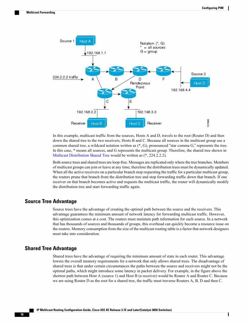
In this example, multicast traffic from the sources, Hosts A and D, travels to the root (Router D) and thendown the shared tree to the two receivers, Hosts B and C. Because all sources in the multicast group use acommon shared tree, a wildcard notation written as (*, G), pronounced “star comma G,” represents the tree.In this case, * means all sources, and G represents the multicast group. Therefore, the shared tree shown inMulticast Distribution Shared Tree would be written as (*, 224.2.2.2).
Both source trees and shared trees are loop-free.Messages are replicated only where the tree branches.Membersof multicast groups can join or leave at any time; therefore the distribution trees must be dynamically updated.When all the active receivers on a particular branch stop requesting the traffic for a particular multicast group,the routers prune that branch from the distribution tree and stop forwarding traffic down that branch. If onereceiver on that branch becomes active and requests the multicast traffic, the router will dynamically modifythe distribution tree and start forwarding traffic again.
Source Tree AdvantageSource trees have the advantage of creating the optimal path between the source and the receivers. Thisadvantage guarantees the minimum amount of network latency for forwarding multicast traffic. However,this optimization comes at a cost. The routers must maintain path information for each source. In a networkthat has thousands of sources and thousands of groups, this overhead can quickly become a resource issue onthe routers. Memory consumption from the size of the multicast routing table is a factor that network designersmust take into consideration.
Shared Tree AdvantageShared trees have the advantage of requiring the minimum amount of state in each router. This advantagelowers the overall memory requirements for a network that only allows shared trees. The disadvantage ofshared trees is that under certain circumstances the paths between the source and receivers might not be theoptimal paths, which might introduce some latency in packet delivery. For example, in the figure above theshortest path between Host A (source 1) and Host B (a receiver) would be Router A and Router C. Becausewe are using Router D as the root for a shared tree, the traffic must traverse Routers A, B, D and then C.
IP Multicast Routing Configuration Guide, Cisco IOS XE Release 3.7E and Later(Catalyst 3850 Switches)16
Configuring PIMMulticast Forwarding

Network designers must carefully consider the placement of the rendezvous point (RP) when implementinga shared tree-only environment.
In unicast routing, traffic is routed through the network along a single path from the source to the destinationhost. A unicast router does not consider the source address; it considers only the destination address and howto forward the traffic toward that destination. The router scans through its routing table for the destinationaddress and then forwards a single copy of the unicast packet out the correct interface in the direction of thedestination.
In multicast forwarding, the source is sending traffic to an arbitrary group of hosts that are represented by amulticast group address. The multicast router must determine which direction is the upstream direction (towardthe source) and which one is the downstream direction (or directions) toward the receivers. If there are multipledownstream paths, the router replicates the packet and forwards it down the appropriate downstream paths(best unicast route metric)--which is not necessarily all paths. Forwarding multicast traffic away from thesource, rather than to the receiver, is called Reverse Path Forwarding (RPF). RPF is described in the followingsection.
PIM Shared Tree and Source TreeBy default, members of a group receive data from senders to the group across a single data-distribution treerooted at the RP.
The following figure shows this type of shared-distribution tree. Data from senders is delivered to the RP fordistribution to group members joined to the shared tree.Figure 3: Shared Tree and Source Tree (Shortest-Path Tree)
If the data rate warrants, leaf routers (routers without any downstream connections) on the shared tree canuse the data distribution tree rooted at the source. This type of distribution tree is called a shortest-path treeor source tree. By default, the software switches to a source tree upon receiving the first data packet from asource.
This process describes the move from a shared tree to a source tree:
1 A receiver joins a group; leaf Router C sends a join message toward the RP.
IP Multicast Routing Configuration Guide, Cisco IOS XE Release 3.7E and Later(Catalyst 3850 Switches) 17
Configuring PIMMulticast Forwarding

2 The RP puts a link to Router C in its outgoing interface list.
3 A source sends data; Router A encapsulates the data in a register message and sends it to the RP.
4 The RP forwards the data down the shared tree to Router C and sends a join message toward the source.At this point, data might arrive twice at Router C, once encapsulated and once natively.
5 When data arrives natively (unencapsulated) at the RP, it sends a register-stop message to Router A.
6 By default, reception of the first data packet prompts Router C to send a join message toward the source.
7 When Router C receives data on (S, G), it sends a prune message for the source up the shared tree.
8 The RP deletes the link to Router C from the outgoing interface of (S, G). The RP triggers a prune messagetoward the source.
Join and prune messages are sent for sources and RPs. They are sent hop-by-hop and are processed by eachPIM device along the path to the source or RP. Register and register-stop messages are not sent hop-by-hop.They are sent by the designated router that is directly connected to a source and are received by the RP forthe group.
Multiple sources sending to groups use the shared tree. You can configure the PIM device to stay on the sharedtree.
The change from shared to source tree happens when the first data packet arrives at the last-hop router. Thischange depends upon the threshold that is configured by using the ip pim spt-threshold global configurationcommand.
The shortest-path tree requires more memory than the shared tree but reduces delay. Youmay want to postponeits use. Instead of allowing the leaf router to immediately move to the shortest-path tree, you can specify thatthe traffic must first reach a threshold.
You can configure when a PIM leaf router should join the shortest-path tree for a specified group. If a sourcesends at a rate greater than or equal to the specified kbps rate, the multilayer switch triggers a PIM join messagetoward the source to construct a source tree (shortest-path tree). If the traffic rate from the source drops belowthe threshold value, the leaf router switches back to the shared tree and sends a prune message toward thesource.
You can specify to which groups the shortest-path tree threshold applies by using a group list (a standardaccess list). If a value of 0 is specified or if the group list is not used, the threshold applies to all groups.
Related Topics
Delaying the Use of PIM Shortest-Path Tree (CLI), on page 47
Reverse Path ForwardingIn unicast routing, traffic is routed through the network along a single path from the source to the destinationhost. A unicast router does not consider the source address; it considers only the destination address and howto forward the traffic toward that destination. The router scans through its routing table for the destinationnetwork and then forwards a single copy of the unicast packet out the correct interface in the direction of thedestination.
In multicast forwarding, the source is sending traffic to an arbitrary group of hosts that are represented by amulticast group address. The multicast router must determine which direction is the upstream direction (towardthe source) and which one is the downstream direction (or directions) toward the receivers. If there are multipledownstream paths, the router replicates the packet and forwards it down the appropriate downstream paths(best unicast route metric)--which is not necessarily all paths. Forwarding multicast traffic away from the
IP Multicast Routing Configuration Guide, Cisco IOS XE Release 3.7E and Later(Catalyst 3850 Switches)18
Configuring PIMMulticast Forwarding

source, rather than to the receiver, is called Reverse Path Forwarding (RPF). RPF is an algorithm used forforwarding multicast datagrams.
Protocol Independent Multicast (PIM) uses the unicast routing information to create a distribution tree alongthe reverse path from the receivers towards the source. The multicast routers then forward packets along thedistribution tree from the source to the receivers. RPF is a key concept in multicast forwarding. It enablesrouters to correctly forward multicast traffic down the distribution tree. RPF makes use of the existing unicastrouting table to determine the upstream and downstream neighbors. A router will forward a multicast packetonly if it is received on the upstream interface. This RPF check helps to guarantee that the distribution treewill be loop-free.
RPF CheckWhen a multicast packet arrives at a router, the router performs an RPF check on the packet. If the RPF checksucceeds, the packet is forwarded. Otherwise, it is dropped.
For traffic flowing down a source tree, the RPF check procedure works as follows:
1 The router looks up the source address in the unicast routing table to determine if the packet has arrivedon the interface that is on the reverse path back to the source.
2 If the packet has arrived on the interface leading back to the source, the RPF check succeeds and the packetis forwarded out the interfaces present in the outgoing interface list of a multicast routing table entry.
3 If the RPF check in Step 2 fails, the packet is dropped.
The figure shows an example of an unsuccessful RPF check.
Figure 4: RPF Check Fails
As the figure illustrates, a multicast packet from source 151.10.3.21 is received on serial interface 0 (S0). Acheck of the unicast route table shows that S1 is the interface this router would use to forward unicast data to151.10.3.21. Because the packet has arrived on interface S0, the packet is discarded.
IP Multicast Routing Configuration Guide, Cisco IOS XE Release 3.7E and Later(Catalyst 3850 Switches) 19
Configuring PIMMulticast Forwarding

The figure shows an example of a successful RPF check.
Figure 5: RPF Check Succeeds
In this example, the multicast packet has arrived on interface S1. The router refers to the unicast routing tableand finds that S1 is the correct interface. The RPF check passes, and the packet is forwarded.
PIM uses both source trees and RP-rooted shared trees to forward datagrams. The RPF check is performeddifferently for each:
• If a PIM router or multilayer switch has a source-tree state (that is, an (S, G) entry is present in themulticast routing table), it performs the RPF check against the IP address of the source of the multicastpacket.
• If a PIM router or multilayer switch has a shared-tree state (and no explicit source-tree state), it performsthe RPF check on the RP address (which is known when members join the group).
DVMRP and dense-mode PIM use only source trees and use RPF.
DVMRP is not supported on the switch.Note
Sparse-mode PIM uses the RPF lookup function to decide where it needs to send joins and prunes:
• (S, G) joins (which are source-tree states) are sent toward the source.
• (*,G) joins (which are shared-tree states) are sent toward the RP.
Default PIM Routing ConfigurationThis table displays the default PIM routing configuration for the switch.
Table 1: Default Multicast Routing Configuration
Default SettingFeature
Disabled on all interfaces.Multicast routing
Version 2.PIM version
No mode is defined.PIM mode
IP Multicast Routing Configuration Guide, Cisco IOS XE Release 3.7E and Later(Catalyst 3850 Switches)20
Configuring PIMDefault PIM Routing Configuration

Default SettingFeature
None configured.PIM stub routing
None configured.PIM RP address
Disabled.PIM domain border
None.PIM multicast boundary
Disabled.Candidate BSRs
Disabled.Candidate RPs
0 kb/s.Shortest-path tree threshold rate
30 seconds.PIM router query message interval
How to Configure PIM
Enabling PIM Stub Routing (CLI)This procedure is optional.
SUMMARY STEPS
1. enable2. configure terminal3. interface interface-id4. ip pim passive5. end6. show ip pim interface7. show ip igmp groups detail8. show ip mroute9. show running-config10. copy running-config startup-config
DETAILED STEPS
PurposeCommand or Action
Enables privileged EXEC mode. Enter your password if prompted.enableStep 1
IP Multicast Routing Configuration Guide, Cisco IOS XE Release 3.7E and Later(Catalyst 3850 Switches) 21
Configuring PIMHow to Configure PIM

PurposeCommand or Action
Example:
Switch> enable
Enters the global configuration mode.configure terminal
Example:
Switch# configure terminal
Step 2
Specifies the interface on which you want to enable PIM stub routing,and enters interface configuration mode.
interface interface-id
Example:
Switch(config)# interface
Step 3
The specified interface must be one of the following:
• A routed port—A physical port that has been configured as a Layer3 port by entering the no switchport interface configuration
gigabitethernet 1/0/1
command. You will also need to enable IP PIM sparse-dense-modeon the interface, and join the interface as a statically connectedmember to an IGMP static group. For a configuration example, seeExample: Interface Configuration as a Routed Port
• An SVI—A VLAN interface created by using the interface vlanvlan-id global configuration command. You will also need to enableIP PIM sparse-dense-mode on the VLAN, join the VLAN as astatically connected member to an IGMP static group, and thenenable IGMP snooping on the VLAN, the IGMP static group, andphysical interface. For a configuration example, see Example:Interface Configuration as an SVI
These interfaces must have IP addresses assigned to them.
Configures the PIM stub feature on the interface.ip pim passive
Example:
Switch(config-if)# ip pim passive
Step 4
Returns to privileged EXEC mode.end
Example:
Switch(config)# end
Step 5
(Optional) Displays the PIM stub that is enabled on each interface.show ip pim interface
Example:
Switch# show ip pim interface
Step 6
IP Multicast Routing Configuration Guide, Cisco IOS XE Release 3.7E and Later(Catalyst 3850 Switches)22
Configuring PIMEnabling PIM Stub Routing (CLI)

PurposeCommand or Action
(Optional) Displays the interested clients that have joined the specificmulticast source group.
show ip igmp groups detail
Example:
Switch# show ip igmp groups detail
Step 7
(Optional) Displays the IP multicast routing table.show ip mroute
Example:
Switch# show ip mroute
Step 8
Verifies your entries.show running-config
Example:
Switch# show running-config
Step 9
(Optional) Saves your entries in the configuration file.copy running-config startup-config
Example:
Switch# copy running-config
Step 10
startup-config
Related Topics
PIM Stub Routing, on page 8
Example: Enabling PIM Stub Routing, on page 61Example: Verifying PIM Stub Routing, on page 62Restrictions for Configuring PIM Stub Routing, on page 3
Configuring a Rendezvous PointYou must have a rendezvous point (RP), if the interface is in sparse-dense mode and if you want to handlethe group as a sparse group. You can use these methods:
• By manually assigning an RP to multicast groups.
• As a standalone, Cisco-proprietary protocol separate from PIMv1, which includes:
• Setting up Auto-RP in a new internetwork
• Adding Auto-RP to an existing sparse-mode cloud
• Preventing join messages to false RPs
• Filtering incoming RP announcement messages
IP Multicast Routing Configuration Guide, Cisco IOS XE Release 3.7E and Later(Catalyst 3850 Switches) 23
Configuring PIMConfiguring a Rendezvous Point

• By using a standards track protocol in the Internet Engineering Task Force (IETF), which includesconfiguring PIMv2 BSR .
You can use Auto-RP, BSR, or a combination of both, depending on the PIM version that you are runningand the types of routers in your network. For information about working with different PIM versions inyour network, see PIMv1 and PIMv2 Interoperability, on page 2.
Note
Related Topics
Configuring the Candidate RPs (CLI), on page 40
Rendezvous Points, on page 9
Manually Assigning an RP to Multicast Groups (CLI)If the rendezvous point (RP) for a group is learned through a dynamic mechanism (such as Auto-RP or BSR),you need not perform this task for that RP.
Senders of multicast traffic announce their existence through register messages received from the sourcefirst-hop router (designated router) and forwarded to the RP. Receivers of multicast packets use RPs to joina multicast group by using explicit join messages.
RPs are not members of the multicast group; they serve as ameeting place for multicast sources and groupmembers.
Note
You can configure a single RP for multiple groups defined by an access list. If there is no RP configured fora group, the multilayer switch responds to the group as dense and uses the dense-mode PIM techniques.
This procedure is optional.
SUMMARY STEPS
1. enable2. configure terminal3. ip pim rp-address ip-address [access-list-number] [override]4. access-list access-list-number {deny | permit} source [source-wildcard]5. end6. show running-config7. copy running-config startup-config
DETAILED STEPS
PurposeCommand or Action
Enables privileged EXEC mode. Enter your password if prompted.enableStep 1
IP Multicast Routing Configuration Guide, Cisco IOS XE Release 3.7E and Later(Catalyst 3850 Switches)24
Configuring PIMConfiguring a Rendezvous Point

PurposeCommand or Action
Example:
Switch> enable
Enters the global configuration mode.configure terminal
Example:
Switch# configure terminal
Step 2
Configures the address of a PIM RP.ip pim rp-address ip-address[access-list-number] [override]
Step 3
By default, no PIM RP address is configured. You must configure the IPaddress of RPs on all routers and multilayer switches (including the RP).
Example:
Switch(config)# ip pim rp-addressIf there is no RP configured for a group, the switch treats the groupas dense, using the dense-mode PIM techniques.
Note
10.1.1.1 20 override A PIM device can be an RP for more than one group. Only one RP addresscan be used at a time within a PIM domain. The access list conditions specifyfor which groups the device is an RP.
• For ip-address, enter the unicast address of the RP in dotted-decimalnotation.
• (Optional) For access-list-number, enter an IP standard access list numberfrom 1 to 99. If no access list is configured, the RP is used for all groups.
• (Optional) The override keyword indicates that if there is a conflictbetween the RP configured with this command and one learned byAuto-RP or BSR, the RP configured with this command prevails.
Creates a standard access list, repeating the command as many times asnecessary.
access-list access-list-number {deny |permit} source [source-wildcard]
Step 4
Example:
Switch(config)# access-list 25
• For access-list-number, enter the access list number specified in Step 2.
• The deny keyword denies access if the conditions are matched.permit 10.5.0.1 255.224.0.0 • The permit keyword permits access if the conditions are matched.
• For source, enter the multicast group address for which the RP shouldbe used.
• (Optional) For source-wildcard, enter the wildcard bits in dotted decimalnotation to be applied to the source. Place ones in the bit positions thatyou want to ignore.
The access list is always terminated by an implicit deny statement foreverything.
IP Multicast Routing Configuration Guide, Cisco IOS XE Release 3.7E and Later(Catalyst 3850 Switches) 25
Configuring PIMConfiguring a Rendezvous Point

PurposeCommand or Action
Returns to privileged EXEC mode.end
Example:
Switch(config)# end
Step 5
Verifies your entries.show running-config
Example:
Switch# show running-config
Step 6
(Optional) Saves your entries in the configuration file.copy running-config startup-config
Example:
Switch# copy running-config
Step 7
startup-config
Related Topics
Example: Manually Assigning an RP to Multicast Groups, on page 62
Setting Up Auto-RP in a New Internetwork (CLI)If you are setting up Auto-RP in a new internetwork, you do not need a default RP because you configure allthe interfaces for sparse-dense mode.
Omit Step 3 in the following procedure, if you want to configure a PIM router as the RP for the localgroup.
Note
IP Multicast Routing Configuration Guide, Cisco IOS XE Release 3.7E and Later(Catalyst 3850 Switches)26
Configuring PIMConfiguring a Rendezvous Point

SUMMARY STEPS
1. enable2. show running-config3. configure terminal4. ip pim send-rp-announce interface-id scope ttl group-list access-list-number interval seconds5. access-list access-list-number {deny | permit} source [source-wildcard]6. ip pim send-rp-discovery scope ttl7. end8. show running-config9. show ip pim rp mapping10. show ip pim rp11. copy running-config startup-config
DETAILED STEPS
PurposeCommand or Action
Enables privileged EXEC mode. Enter your password if prompted.enableStep 1
Example:
Switch> enable
Verifies that a default RP is already configured on all PIM devices and theRP in the sparse-mode network. It was previously configured with the ip pimrp-address global configuration command.
show running-config
Example:
Switch# show running-config
Step 2
This step is not required for spare-dense-modeenvironments.
Note
The selected RP should have good connectivity and be available across thenetwork. Use this RP for the global groups (for example, 224.x.x.x and otherglobal groups). Do not reconfigure the group address range that this RP serves.RPs dynamically discovered through Auto-RP take precedence over staticallyconfigured RPs. Assume that it is desirable to use a second RP for the localgroups.
Enters the global configuration mode.configure terminal
Example:
Switch# configure terminal
Step 3
Configures another PIM device to be the candidate RP for local groups.ip pim send-rp-announce interface-idscope ttl group-list access-list-numberinterval seconds
Step 4
• For interface-id, enter the interface type and number that identifies theRP address. Valid interfaces include physical ports, port channels, andVLANs.
IP Multicast Routing Configuration Guide, Cisco IOS XE Release 3.7E and Later(Catalyst 3850 Switches) 27
Configuring PIMConfiguring a Rendezvous Point

PurposeCommand or Action
Example:
Switch(config)# ip pim
• For scope ttl, specify the time-to-live value in hops. Enter a hop countthat is high enough so that the RP-announcemessages reach all mappingagents in the network. There is no default setting. The range is 1 to 255.
• For group-list access-list-number, enter an IP standard access list numberfrom 1 to 99. If no access list is configured, the RP is used for all groups.
send-rp-announce gigabitethernet1/0/5 scope 20 group-list 10interval 120
• For interval seconds, specify how often the announcement messagesmust be sent. The default is 60 seconds. The range is 1 to 16383.
Creates a standard access list, repeating the command as many times asnecessary.
access-list access-list-number {deny |permit} source [source-wildcard]
Step 5
Example:
Switch(config)# access-list 10
• For access-list-number, enter the access list number specified in Step 3.
• The deny keyword denies access if the conditions are matched.permit 10.10.0.0 • The permit keyword permits access if the conditions are matched.
• For source, enter the multicast group address range for which the RPshould be used.
• (Optional) For source-wildcard, enter the wildcard bits in dotted decimalnotation to be applied to the source. Place ones in the bit positions thatyou want to ignore.
Recall that the access list is always terminated by an implicit denystatement for everything.
Note
Finds a switch whose connectivity is not likely to be interrupted, and assignit the role of RP-mapping agent.
ip pim send-rp-discovery scope ttl
Example:
Switch(config)# ip pim
Step 6
For scope ttl, specify the time-to-live value in hops to limit the RP discoverypackets. All devices within the hop count from the source device receive theAuto-RP discovery messages. These messages tell other devices whichsend-rp-discovery scope 50group-to-RP mapping to use to avoid conflicts (such as overlappinggroup-to-RP ranges). There is no default setting. The range is 1 to 255.
Returns to privileged EXEC mode.end
Example:
Switch(config)# end
Step 7
Verifies your entries.show running-config
Example:
Switch# show running-config
Step 8
Displays active RPs that are cached with associated multicast routing entries.show ip pim rp mappingStep 9
IP Multicast Routing Configuration Guide, Cisco IOS XE Release 3.7E and Later(Catalyst 3850 Switches)28
Configuring PIMConfiguring a Rendezvous Point

PurposeCommand or Action
Example:Switch# show ip pim rp mapping
Displays the information cached in the routing table.show ip pim rpStep 10
Example:
Switch# show ip pim rp
(Optional) Saves your entries in the configuration file.copy running-config startup-config
Example:
Switch# copy running-config
Step 11
startup-config
Related Topics
Auto-RP, on page 10Example: Configuring Auto-RP, on page 62
Example: Sparse Mode with Auto-RP , on page 63Restrictions for Configuring Auto-RP and BSR, on page 3
Restrictions for Auto-RP Enhancement, on page 5
Adding Auto-RP to an Existing Sparse-Mode Cloud (CLI)This section contains suggestions for the initial deployment of Auto-RP into an existing sparse-mode cloudto minimize disruption of the existing multicast infrastructure.
This procedure is optional.
IP Multicast Routing Configuration Guide, Cisco IOS XE Release 3.7E and Later(Catalyst 3850 Switches) 29
Configuring PIMConfiguring a Rendezvous Point

SUMMARY STEPS
1. enable2. show running-config3. configure terminal4. ip pim send-rp-announce interface-id scope ttl group-list access-list-number interval seconds5. access-list access-list-number {deny | permit} source [source-wildcard]6. ip pim send-rp-discovery scope ttl7. end8. show running-config9. show ip pim rp mapping10. show ip pim rp11. copy running-config startup-config
DETAILED STEPS
PurposeCommand or Action
Enables privileged EXEC mode. Enter your password if prompted.enableStep 1
Example:
Switch> enable
Verifies that a default RP is already configured on all PIM devices and the RPin the sparse-mode network. It was previously configured with the ip pimrp-address global configuration command.
show running-config
Example:
Switch# show running-config
Step 2
This step is not required for spare-dense-modeenvironments.
Note
The selected RP should have good connectivity and be available across thenetwork. Use this RP for the global groups (for example, 224.x.x.x and otherglobal groups). Do not reconfigure the group address range that this RP serves.RPs dynamically discovered through Auto-RP take precedence over staticallyconfigured RPs. Assume that it is desirable to use a second RP for the localgroups.
Enters the global configuration mode.configure terminal
Example:
Switch# configure terminal
Step 3
Configures another PIM device to be the candidate RP for local groups.ip pim send-rp-announce interface-idscope ttl group-list access-list-numberinterval seconds
Step 4
• For interface-id, enter the interface type and number that identifies theRP address. Valid interfaces include physical ports, port channels, andVLANs.
IP Multicast Routing Configuration Guide, Cisco IOS XE Release 3.7E and Later(Catalyst 3850 Switches)30
Configuring PIMConfiguring a Rendezvous Point

PurposeCommand or Action
Example:
Switch(config)# ip pim
• For scope ttl, specify the time-to-live value in hops. Enter a hop countthat is high enough so that the RP-announce messages reach all mappingagents in the network. There is no default setting. The range is 1 to 255.
• For group-list access-list-number, enter an IP standard access list numberfrom 1 to 99. If no access list is configured, the RP is used for all groups.
send-rp-announce gigabitethernet1/0/5 scope 20 group-list 10interval 120
• For interval seconds, specify how often the announcement messagesmust be sent. The default is 60 seconds. The range is 1 to 16383.
Creates a standard access list, repeating the command as many times asnecessary.
access-list access-list-number {deny |permit} source [source-wildcard]
Step 5
Example:
Switch(config)# access-list 10
• For access-list-number, enter the access list number specified in Step 3.
• The deny keyword denies access if the conditions are matched.permit 224.0.0.0 15.255.255.255 • The permit keyword permits access if the conditions are matched.
• For source, enter the multicast group address range for which the RPshould be used.
• (Optional) For source-wildcard, enter the wildcard bits in dotted decimalnotation to be applied to the source. Place ones in the bit positions thatyou want to ignore.
Recall that the access list is always terminated by an implicit deny statementfor everything.
Finds a switch whose connectivity is not likely to be interrupted, and assignsit the role of RP-mapping agent.
ip pim send-rp-discovery scope ttl
Example:
Switch(config)# ip pimsend-rp-discovery scope 50
Step 6
For scope ttl, specify the time-to-live value in hops to limit the RP discoverypackets. All devices within the hop count from the source device receive theAuto-RP discovery messages. These messages tell other devices whichgroup-to-RP mapping to use to avoid conflicts (such as overlappinggroup-to-RP ranges). There is no default setting. The range is 1 to 255.
To remove the switch as the RP-mapping agent, use the no ip pimsend-rp-discovery global configuration command.
Note
Returns to privileged EXEC mode.end
Example:
Switch(config)# end
Step 7
Verifies your entries.show running-config
Example:
Switch# show running-config
Step 8
IP Multicast Routing Configuration Guide, Cisco IOS XE Release 3.7E and Later(Catalyst 3850 Switches) 31
Configuring PIMConfiguring a Rendezvous Point

PurposeCommand or Action
Displays active RPs that are cached with associated multicast routing entries.show ip pim rp mappingStep 9
Example:Switch#show ip pim rp mapping
Displays the information cached in the routing table.show ip pim rpStep 10
Example:
Switch# show ip pim rp
(Optional) Saves your entries in the configuration file.copy running-config startup-config
Example:
Switch# copy running-config
Step 11
startup-config
Related Topics
Sparse-Dense Mode for Auto-RP, on page 12
Preventing Join Messages to False RPs (CLI)Determine whether the ip pim accept-rp command was previously configured throughout the network byusing the show running-config privileged EXEC command. If the ip pim accept-rp command is not configuredon any device, this problem can be addressed later. In those routers or multilayer switches already configuredwith the ip pim accept-rp command, you must enter the command again to accept the newly advertised RP.
To accept all RPs advertised with Auto-RP and reject all other RPs by default, use the ip pim accept-rpauto-rp global configuration command.
This procedure is optional.
Related Topics
Example: Preventing Join Messages to False RPs, on page 64
Filtering Incoming RP Announcement Messages (CLI)You can add configuration commands to the mapping agents to prevent a maliciously configured router frommasquerading as a candidate RP and causing problems.
This procedure is optional.
IP Multicast Routing Configuration Guide, Cisco IOS XE Release 3.7E and Later(Catalyst 3850 Switches)32
Configuring PIMConfiguring a Rendezvous Point

SUMMARY STEPS
1. enable2. configure terminal3. ip pim rp-announce-filter rp-list access-list-number group-list access-list-number4. access-list access-list-number {deny | permit} source [source-wildcard]5. end6. show running-config7. copy running-config startup-config
DETAILED STEPS
PurposeCommand or Action
Enables privileged EXEC mode. Enter your password if prompted.enableStep 1
Example:
Switch> enable
Enters the global configuration mode.configure terminal
Example:
Switch# configure terminal
Step 2
Filters incoming RP announcement messages.ip pim rp-announce-filter rp-listaccess-list-number group-listaccess-list-number
Step 3
Enter this command on each mapping agent in the network. Without thiscommand, all incoming RP-announce messages are accepted by default.
Example:
Switch(config)# ip pim
For rp-list access-list-number, configure an access list of candidate RPaddresses that, if permitted, is accepted for the group ranges supplied in thegroup-list access-list-number variable. If this variable is omitted, the filterapplies to all multicast groups.rp-announce-filter rp-list 10
group-list 14
If more than one mapping agent is used, the filters must be consistent acrossall mapping agents to ensure that no conflicts occur in the group-to-RPmapping information.
Creates a standard access list, repeating the command as many times asnecessary.
access-list access-list-number {deny |permit} source [source-wildcard]
Step 4
Example:
Switch(config)# access-list 10
• For access-list-number, enter the access list number specified in Step2.
• The deny keyword denies access if the conditions are matched.permit 10.8.1.0 255.255.224.0
• The permit keyword permits access if the conditions are matched.
• Create an access list that specifies from which routers and multilayerswitches the mapping agent accepts candidate RP announcements(rp-list ACL).
IP Multicast Routing Configuration Guide, Cisco IOS XE Release 3.7E and Later(Catalyst 3850 Switches) 33
Configuring PIMConfiguring a Rendezvous Point
PurposeCommand or Action
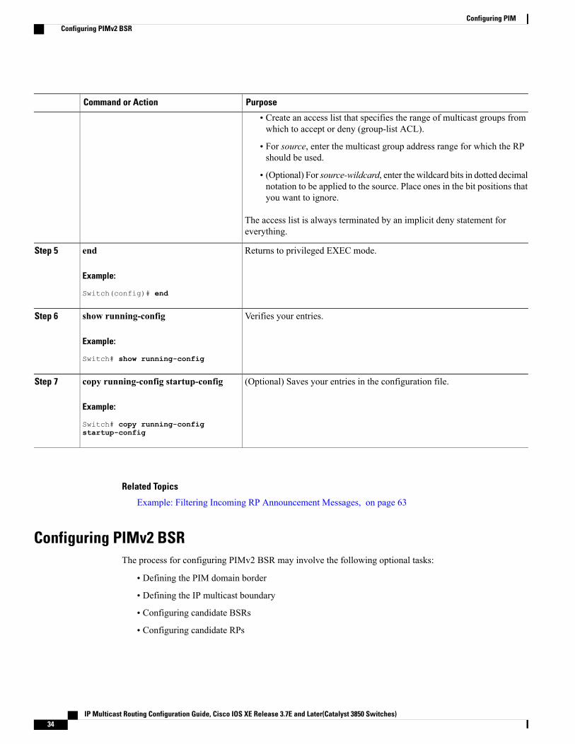
• Create an access list that specifies the range of multicast groups fromwhich to accept or deny (group-list ACL).
• For source, enter the multicast group address range for which the RPshould be used.
• (Optional) For source-wildcard, enter the wildcard bits in dotted decimalnotation to be applied to the source. Place ones in the bit positions thatyou want to ignore.
The access list is always terminated by an implicit deny statement foreverything.
Returns to privileged EXEC mode.end
Example:
Switch(config)# end
Step 5
Verifies your entries.show running-config
Example:
Switch# show running-config
Step 6
(Optional) Saves your entries in the configuration file.copy running-config startup-config
Example:
Switch# copy running-config
Step 7
startup-config
Related Topics
Example: Filtering Incoming RP Announcement Messages, on page 63
Configuring PIMv2 BSRThe process for configuring PIMv2 BSR may involve the following optional tasks:
• Defining the PIM domain border
• Defining the IP multicast boundary
• Configuring candidate BSRs
• Configuring candidate RPs
IP Multicast Routing Configuration Guide, Cisco IOS XE Release 3.7E and Later(Catalyst 3850 Switches)34
Configuring PIMConfiguring PIMv2 BSR

Related Topics
Configuring Candidate BSRs (CLI), on page 39
PIMv2 Bootstrap Router, on page 13
Defining the PIM Domain Border (CLI)Perform the following steps to configure the PIM domain border. This procedure is optional.
SUMMARY STEPS
1. enable2. configure terminal3. interface interface-id4. ip pim bsr-border5. end6. show running-config7. copy running-config startup-config
DETAILED STEPS
PurposeCommand or Action
Enables privileged EXEC mode. Enter your password if prompted.enableStep 1
Example:
Switch> enable
Enters the global configuration mode.configure terminal
Example:
Switch# configure terminal
Step 2
Specifies the interface to be configured, and enters interface configurationmode.
interface interface-id
Example:
Switch(config)# interface
Step 3
The specified interface must be one of the following:
• A routed port—A physical port that has been configured as a Layer 3 portby entering the no switchport interface configuration command. You
gigabitethernet 1/0/1
will also need to enable IP PIM sparse-dense-mode on the interface, andjoin the interface as a statically connected member to an IGMP staticgroup. For a configuration example, see Example: Interface Configurationas a Routed Port
• An SVI—A VLAN interface created by using the interface vlan vlan-idglobal configuration command. You will also need to enable IP PIMsparse-dense-mode on the VLAN, join the VLAN as a statically connected
IP Multicast Routing Configuration Guide, Cisco IOS XE Release 3.7E and Later(Catalyst 3850 Switches) 35
Configuring PIMConfiguring PIMv2 BSR

PurposeCommand or Action
member to an IGMP static group, and then enable IGMP snooping on theVLAN, the IGMP static group, and physical interface. For a configurationexample, see Example: Interface Configuration as an SVI
These interfaces must have IP addresses assigned to them.
Defines a PIM bootstrap message boundary for the PIM domain.ip pim bsr-borderStep 4
Example:
Switch(config-if)# ip pim
Enter this command on each interface that connects to other bordering PIMdomains. This command instructs the switch to neither send nor receive PIMv2BSR messages on this interface.
bsr-border To remove the PIM border, use the no ip pim bsr-border interfaceconfiguration command.
Note
Returns to privileged EXEC mode.end
Example:
Switch(config)# end
Step 5
Verifies your entries.show running-config
Example:
Switch# show running-config
Step 6
(Optional) Saves your entries in the configuration file.copy running-config startup-config
Example:
Switch# copy running-config
Step 7
startup-config
Related Topics
PIM Domain Border, on page 14
Defining the IP Multicast Boundary (CLI)You define a multicast boundary to prevent Auto-RP messages from entering the PIM domain. You createan access list to deny packets destined for 224.0.1.39 and 224.0.1.40, which carry Auto-RP information.
This procedure is optional.
IP Multicast Routing Configuration Guide, Cisco IOS XE Release 3.7E and Later(Catalyst 3850 Switches)36
Configuring PIMConfiguring PIMv2 BSR

SUMMARY STEPS
1. enable2. configure terminal3. access-list access-list-number deny source [source-wildcard]4. interface interface-id5. ip multicast boundary access-list-number6. end7. show running-config8. copy running-config startup-config
DETAILED STEPS
PurposeCommand or Action
Enables privileged EXEC mode. Enter your password if prompted.enableStep 1
Example:
Switch> enable
Enters the global configuration mode.configure terminal
Example:
Switch# configure terminal
Step 2
Creates a standard access list, repeating the command as many times asnecessary.
access-list access-list-number deny source[source-wildcard]
Step 3
Example:Switch(config)#access-list 12 deny 224.0.1.39
• For access-list-number, the range is 1 to 99.
• The deny keyword denies access if the conditions are matched.access-list 12 deny 224.0.1.40 • For source, enter multicast addresses 224.0.1.39 and 224.0.1.40, which
carry Auto-RP information.
• (Optional) For source-wildcard, enter the wildcard bits in dotted decimalnotation to be applied to the source. Place ones in the bit positions thatyou want to ignore.
The access list is always terminated by an implicit deny statement foreverything.
Specifies the interface to be configured, and enters interface configurationmode.
interface interface-id
Example:
Switch(config)# interface
Step 4
The specified interface must be one of the following:
• A routed port—A physical port that has been configured as a Layer 3port by entering the no switchport interface configuration command.
gigabitethernet 1/0/1
Youwill also need to enable IP PIM sparse-dense-mode on the interface,
IP Multicast Routing Configuration Guide, Cisco IOS XE Release 3.7E and Later(Catalyst 3850 Switches) 37
Configuring PIMConfiguring PIMv2 BSR

PurposeCommand or Action
and join the interface as a statically connected member to an IGMPstatic group. For a configuration example, see Example: InterfaceConfiguration as a Routed Port
• An SVI—AVLAN interface created by using the interface vlan vlan-idglobal configuration command. You will also need to enable IP PIMsparse-dense-mode on the VLAN, join the VLAN as a staticallyconnected member to an IGMP static group, and then enable IGMPsnooping on the VLAN, the IGMP static group, and physical interface.For a configuration example, see Example: Interface Configuration asan SVI
These interfaces must have IP addresses assigned to them.
Configures the boundary, specifying the access list you created in Step 2.ipmulticast boundary access-list-numberStep 5
Example:
Switch(config-if)# ip multicastboundary 12
Returns to privileged EXEC mode.end
Example:
Switch(config)# end
Step 6
Verifies your entries.show running-config
Example:
Switch# show running-config
Step 7
(Optional) Saves your entries in the configuration file.copy running-config startup-config
Example:
Switch# copy running-config
Step 8
startup-config
Related Topics
Multicast Boundaries, on page 11
Example: Defining the IP Multicast Boundary to Deny Auto-RP Information, on page 63
IP Multicast BoundaryMulticast Group Transmission SchemeExample: Configuring an IP Multicast Boundary
IP Multicast Routing Configuration Guide, Cisco IOS XE Release 3.7E and Later(Catalyst 3850 Switches)38
Configuring PIMConfiguring PIMv2 BSR

Configuring Candidate BSRs (CLI)You can configure one or more candidate BSRs. The devices serving as candidate BSRs should have goodconnectivity to other devices and be in the backbone portion of the network.
This procedure is optional.
SUMMARY STEPS
1. enable2. configure terminal3. ip pim bsr-candidate interface-id hash-mask-length [priority]4. end5. show running-config6. copy running-config startup-config
DETAILED STEPS
PurposeCommand or Action
Enables privileged EXEC mode. Enter your password if prompted.enableStep 1
Example:
Switch> enable
Enters the global configuration mode.configure terminal
Example:
Switch# configure terminal
Step 2
Configures your switch to be a candidate BSR.ip pim bsr-candidate interface-idhash-mask-length [priority]
Step 3
• For interface-id, enter the interface on this switch from which theBSR address is derived to make it a candidate. This interface must
Example:
Switch(config)# ip pim bsr-candidate
be enabled with PIM. Valid interfaces include physical ports, portchannels, and VLANs.
gigabitethernet 1/0/3 28 100• For hash-mask-length, specify the mask length (32 bits maximum)that is to be ANDedwith the group address before the hash functionis called. All groups with the same seed hash correspond to thesame RP. For example, if this value is 24, only the first 24 bits ofthe group addresses matter.
• (Optional) For priority, enter a number from 0 to 255. The BSRwith the larger priority is preferred. If the priority values are thesame, the device with the highest IP address is selected as the BSR.The default is 0.
IP Multicast Routing Configuration Guide, Cisco IOS XE Release 3.7E and Later(Catalyst 3850 Switches) 39
Configuring PIMConfiguring PIMv2 BSR
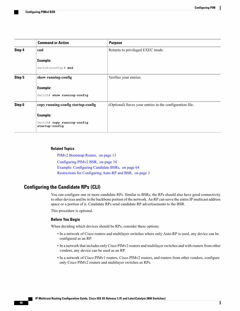
PurposeCommand or Action
Returns to privileged EXEC mode.end
Example:
Switch(config)# end
Step 4
Verifies your entries.show running-config
Example:
Switch# show running-config
Step 5
(Optional) Saves your entries in the configuration file.copy running-config startup-config
Example:
Switch# copy running-config
Step 6
startup-config
Related Topics
PIMv2 Bootstrap Router, on page 13
Configuring PIMv2 BSR, on page 34Example: Configuring Candidate BSRs, on page 64Restrictions for Configuring Auto-RP and BSR, on page 3
Configuring the Candidate RPs (CLI)You can configure one or more candidate RPs. Similar to BSRs, the RPs should also have good connectivityto other devices and be in the backbone portion of the network. An RP can serve the entire IP multicast addressspace or a portion of it. Candidate RPs send candidate RP advertisements to the BSR.
This procedure is optional.
Before You Begin
When deciding which devices should be RPs, consider these options:
• In a network of Cisco routers and multilayer switches where only Auto-RP is used, any device can beconfigured as an RP.
• In a network that includes only Cisco PIMv2 routers andmultilayer switches and with routers from othervendors, any device can be used as an RP.
• In a network of Cisco PIMv1 routers, Cisco PIMv2 routers, and routers from other vendors, configureonly Cisco PIMv2 routers and multilayer switches as RPs.
IP Multicast Routing Configuration Guide, Cisco IOS XE Release 3.7E and Later(Catalyst 3850 Switches)40
Configuring PIMConfiguring PIMv2 BSR
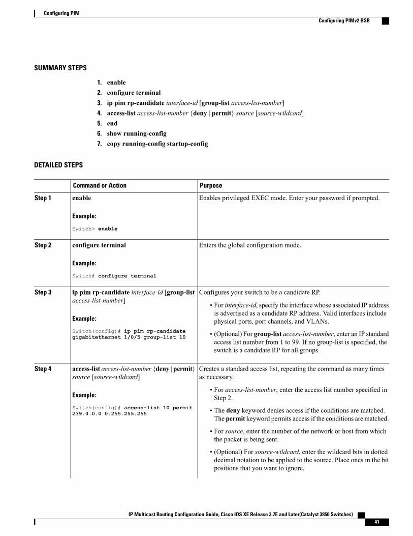
SUMMARY STEPS
1. enable2. configure terminal3. ip pim rp-candidate interface-id [group-list access-list-number]4. access-list access-list-number {deny | permit} source [source-wildcard]5. end6. show running-config7. copy running-config startup-config
DETAILED STEPS
PurposeCommand or Action
Enables privileged EXEC mode. Enter your password if prompted.enableStep 1
Example:
Switch> enable
Enters the global configuration mode.configure terminal
Example:
Switch# configure terminal
Step 2
Configures your switch to be a candidate RP.ip pim rp-candidate interface-id [group-listaccess-list-number]
Step 3
• For interface-id, specify the interface whose associated IP addressis advertised as a candidate RP address. Valid interfaces includephysical ports, port channels, and VLANs.Example:
Switch(config)# ip pim rp-candidate • (Optional) For group-list access-list-number, enter an IP standardaccess list number from 1 to 99. If no group-list is specified, theswitch is a candidate RP for all groups.
gigabitethernet 1/0/5 group-list 10
Creates a standard access list, repeating the command as many timesas necessary.
access-list access-list-number {deny | permit}source [source-wildcard]
Step 4
Example:
Switch(config)# access-list 10 permit
• For access-list-number, enter the access list number specified inStep 2.
• The deny keyword denies access if the conditions are matched.The permit keyword permits access if the conditions are matched.
239.0.0.0 0.255.255.255
• For source, enter the number of the network or host from whichthe packet is being sent.
• (Optional) For source-wildcard, enter the wildcard bits in dotteddecimal notation to be applied to the source. Place ones in the bitpositions that you want to ignore.
IP Multicast Routing Configuration Guide, Cisco IOS XE Release 3.7E and Later(Catalyst 3850 Switches) 41
Configuring PIMConfiguring PIMv2 BSR

PurposeCommand or Action
The access list is always terminated by an implicit deny statement foreverything.
Returns to privileged EXEC mode.end
Example:
Switch(config)# end
Step 5
Verifies your entries.show running-config
Example:
Switch# show running-config
Step 6
(Optional) Saves your entries in the configuration file.copy running-config startup-config
Example:
Switch# copy running-config
Step 7
startup-config
Related Topics
Rendezvous Points, on page 9Configuring a Rendezvous Point, on page 23Example: Configuring Candidate RPs, on page 64
Configuring Sparse Mode with Auto-RP(CLI)
Before You Begin
• An interface configured in sparse-dense mode is treated in either sparse mode or dense mode of operation,depending on the mode in which the multicast group operates. You must decide how to configure yourinterfaces.
• All access lists that are needed when Auto-RP is configured should be configured prior to beginning theconfiguration task.
IP Multicast Routing Configuration Guide, Cisco IOS XE Release 3.7E and Later(Catalyst 3850 Switches)42
Configuring PIMConfiguring Sparse Mode with Auto-RP(CLI)

Note • If a group has no known RP and the interface is configured to be sparse-dense mode, the interfaceis treated as if it were in dense mode, and data is flooded over the interface. To avoid this dataflooding, configure the Auto-RP listener and then configure the interface as sparse mode.
•When configuring Auto-RP, you must either configure the Auto-RP listener feature (Step 5) andspecify sparse mode (Step 7) or specify sparse-dense mode (Step 8) .
•When you configure sparse-dense mode, dense mode failover may result in a network dense-modeflood. To avoid this condition, use PIM sparse mode with the Auto-RP listener feature.
Follow this procedure to configure auto-rendezvous point (Auto-RP). Auto-RP can also be optionally usedwith anycast RP.
SUMMARY STEPS
1. enable2. configure terminal3. ip multicast-routing [distributed]4. Either perform Steps 5 through 7 or perform Steps 6 and 8.5. ip pim autorp listener6. interface type number7. ip pim sparse-mode8. ip pim sparse-dense-mode9. exit10. Repeat Steps 1 through 9 on all PIM interfaces.11. ip pim send-rp-announce {interface-type interface-number | ip-address} scope ttl-value [group-list
access-list] [interval seconds] [bidir]12. ip pim send-rp-discovery [interface-type interface-number] scope ttl-value [interval seconds]13. ip pim rp-announce-filter rp-list access-list group-list access-list14. no ip pim dm-fallback15. interface type number16. ip multicast boundary access-list [filter-autorp]17. end18. show ip pim autorp19. show ip pim rp [mapping] [rp-address]20. show ip igmp groups [group-name | group-address| interface-type interface-number] [detail]21. show ip mroute [group-address | group-name] [source-address | source-name] [interface-type
interface-number] [summary] [count] [active kbps]
DETAILED STEPS
PurposeCommand or Action
Enables privileged EXEC mode.enableStep 1
IP Multicast Routing Configuration Guide, Cisco IOS XE Release 3.7E and Later(Catalyst 3850 Switches) 43
Configuring PIMConfiguring Sparse Mode with Auto-RP(CLI)

PurposeCommand or Action
Example:
Switch> enable
• Enter your password if prompted.
Enters global configuration mode.configure terminal
Example:
Switch# configure terminal
Step 2
Enables IP multicast routing.ip multicast-routing [distributed]Step 3
Example:
Switch(config)# ip multicast-routing
• Use the distributed keyword to enabled Multicast DistributedSwitching.
--Either perform Steps 5 through 7 or performSteps 6 and 8.
Step 4
Causes IP multicast traffic for the two Auto-RP groups 224.0.1.39 and224.0.1.40 to be PIM dense mode flooded across interfaces operating inPIM sparse mode.
ip pim autorp listener
Example:
Switch(config)# ip pim autorp listener
Step 5
• Skip this step if you are configuring sparse-dense mode in Step 8.
Selects an interface that is connected to hosts on which PIM can beenabled.
interface type number
Example:
Switch(config)# interfaceGigabitethernet 1/0/0
Step 6
Enables PIM sparse mode on an interface. When configuring Auto-RPin sparse mode, you must also configure the Auto-RP listener in the nextstep.
ip pim sparse-mode
Example:
Switch(config-if)# ip pim sparse-mode
Step 7
• Skip this step if you are configuring sparse-dense mode in Step 8.
Enables PIM sparse-dense mode on an interface.ip pim sparse-dense-modeStep 8
Example:
Switch(config-if)# ip pimsparse-dense-mode
• Skip this step if you configured sparse mode in Step 7.
Exits interface configuration mode and returns to global configurationmode.
exit
Example:
Switch(config-if)# exit
Step 9
IP Multicast Routing Configuration Guide, Cisco IOS XE Release 3.7E and Later(Catalyst 3850 Switches)44
Configuring PIMConfiguring Sparse Mode with Auto-RP(CLI)

PurposeCommand or Action
--Repeat Steps 1 through 9 on all PIM interfaces.Step 10
Sends RP announcements out all PIM-enabled interfaces.ip pim send-rp-announce {interface-typeinterface-number | ip-address} scope ttl-value
Step 11
• Perform this step on the RP device only.[group-list access-list] [interval seconds][bidir] • Use the interface-typeand interface-number arguments to define
which IP address is to be used as the RP address.Example:
Switch(config)# ip pim send-rp-announceloopback0 scope 31 group-list 5
• Use the ip-address argument to specify a directly connected IPaddress as the RP address.
If the ip-address argument is configured for this command, theRP-announce message will be sourced by the interface to whichthis IP address is connected (that is, the source address in theIP header of the RP-announce message is the IP address of thatinterface).
Note
• This example shows that the interface is enabled with a maximumof 31 hops. The IP address by which the device wants to beidentified as RP is the IP address associated with loopback interface0. Access list 5 describes the groups for which this device servesas RP.
Configures the device to be an RP mapping agent.ip pim send-rp-discovery [interface-typeinterface-number] scope ttl-value [intervalseconds]
Step 12
• Perform this step on RP mapping agent devices or on combinedRP/RP mapping agent devices.
Example:
Switch(config)# ip pimsend-rp-discovery loopback 1 scope 31
Auto-RP allows the RP function to run separately on one deviceand the RP mapping agent to run on one or multiple devices. Itis possible to deploy the RP and the RP mapping agent on acombined RP/RP mapping agent device.
Note
• Use the optional interface-type and interface-number argumentsto define which IP address is to be used as the source address ofthe RP mapping agent.
• Use the scope keyword and ttl-value argument to specify theTime-to-Live (TTL) value in the IP header of Auto-RP discoverymessages.
• Use the optional interval keyword and seconds argument to specifythe interval at which Auto-RP discovery messages are sent.
Lowering the interval at which Auto-RP discovery messagesare sent from the default value of 60 seconds results in morefrequent floodings of the group-to-RP mappings. In somenetwork environments, the disadvantages of lowering theinterval (more control packet overhead) may outweigh theadvantages (more frequent group-to-RP mapping updates).
Note
IP Multicast Routing Configuration Guide, Cisco IOS XE Release 3.7E and Later(Catalyst 3850 Switches) 45
Configuring PIMConfiguring Sparse Mode with Auto-RP(CLI)

PurposeCommand or Action
• The example shows limiting the Auto-RP discovery messages to31 hops on loopback interface 1.
Filters incoming RP announcement messages sent from candidate RPs(C-RPs) to the RP mapping agent.
ip pim rp-announce-filter rp-list access-listgroup-list access-list
Step 13
Example:
Switch(config)# ip pim
• Perform this step on the RP mapping agent only.
rp-announce-filter rp-list 1 group-list2
(Optional) Prevents PIM dense mode fallback.no ip pim dm-fallbackStep 14
Example:
Switch(config)# no ip pim dm-fallback
• Skip this step if all interfaces have been configured to operate inPIM sparse mode.
The no ip pim dm-fallback command behavior is enabled bydefault if all the interfaces are configured to operate in PIMsparse mode (using the ip pim sparse-mode command).
Note
Selects an interface that is connected to hosts on which PIM can beenabled.
interface type number
Example:
Switch(config)# interfacegigabitethernet 1/0/0
Step 15
Configures an administratively scoped boundary.ip multicast boundary access-list[filter-autorp]
Step 16
• Perform this step on the interfaces that are boundaries to otherdevices.
Example:
Switch(config-if)# ip multicastboundary 10 filter-autorp
• The access list is not shown in this task.
• An access list entry that uses the deny keyword creates a multicastboundary for packets that match that entry.
Returns to global configuration mode.end
Example:
Switch(config-if)# end
Step 17
(Optional) Displays the Auto-RP information.show ip pim autorp
Example:
Switch# show ip pim autorp
Step 18
IP Multicast Routing Configuration Guide, Cisco IOS XE Release 3.7E and Later(Catalyst 3850 Switches)46
Configuring PIMConfiguring Sparse Mode with Auto-RP(CLI)

PurposeCommand or Action
(Optional) Displays RPs known in the network and shows how the devicelearned about each RP.
show ip pim rp [mapping] [rp-address]
Example:
Switch# show ip pim rp mapping
Step 19
(Optional) Displays themulticast groups having receivers that are directlyconnected to the device and that were learned through Internet GroupManagement Protocol (IGMP).
show ip igmp groups [group-name |group-address| interface-typeinterface-number] [detail]
Step 20
Example:
Switch# show ip igmp groups
• A receiver must be active on the network at the time that thiscommand is issued in order for receiver information to be presenton the resulting display.
(Optional) Displays the contents of the IP multicast routing (mroute)table.
show ipmroute [group-address | group-name][source-address | source-name] [interface-typeinterface-number] [summary] [count] [activekbps]
Step 21
Example:
Switch# show ip mroute cbone-audio
Delaying the Use of PIM Shortest-Path Tree (CLI)Perform these steps to configure a traffic rate threshold that must be reached before multicast routing isswitched from the source tree to the shortest-path tree.
This procedure is optional.
SUMMARY STEPS
1. enable2. configure terminal3. access-list access-list-number {deny | permit} source [source-wildcard]4. ip pim spt-threshold {kbps | infinity} [group-list access-list-number]5. end6. show running-config7. copy running-config startup-config
IP Multicast Routing Configuration Guide, Cisco IOS XE Release 3.7E and Later(Catalyst 3850 Switches) 47
Configuring PIMDelaying the Use of PIM Shortest-Path Tree (CLI)

DETAILED STEPS
PurposeCommand or Action
Enables privileged EXEC mode. Enter your password if prompted.enableStep 1
Example:
Switch> enable
Enters global configuration mode.configure terminal
Example:
Switch# configure terminal
Step 2
Creates a standard access list.access-list access-list-number {deny |permit} source [source-wildcard]
Step 3
• For access-list-number, the range is 1 to 99.
Example:
Switch(config)# access-list 16 permit
• The deny keyword denies access if the conditions are matched.
• The permit keyword permits access if the conditions are matched.225.0.0.0 0.255.255.255
• For source, specify the multicast group to which the threshold willapply.
• (Optional) For source-wildcard, enter the wildcard bits in dotteddecimal notation to be applied to the source. Place ones in the bitpositions that you want to ignore.
The access list is always terminated by an implicit deny statement foreverything.
Specifies the threshold that must be reached before moving toshortest-path tree (spt).
ip pim spt-threshold {kbps | infinity}[group-list access-list-number]
Step 4
Example:
Switch(config)# ip pim spt-threshold
• For kbps, specify the traffic rate in kilobits per second. The defaultis 0 kbps.
Because of switch hardware limitations, 0 kbps is the onlyvalid entry even though the range is 0 to 4294967.
Noteinfinity group-list 16
• Specify infinity if you want all sources for the specified group touse the shared tree, never switching to the source tree.
• (Optional) For group-list access-list-number, specify the accesslist created in Step 2. If the value is 0 or if the group list is not used,the threshold applies to all groups.
IP Multicast Routing Configuration Guide, Cisco IOS XE Release 3.7E and Later(Catalyst 3850 Switches)48
Configuring PIMDelaying the Use of PIM Shortest-Path Tree (CLI)

PurposeCommand or Action
Returns to privileged EXEC mode.end
Example:
Switch(config)# end
Step 5
Verifies your entries.show running-config
Example:
Switch# show running-config
Step 6
(Optional) Saves your entries in the configuration file.copy running-config startup-config
Example:
Switch# copy running-config
Step 7
startup-config
Related Topics
PIM Shared Tree and Source Tree, on page 17
Modifying the PIM Router-Query Message Interval (CLI)PIM routers and multilayer switches send PIM router-query messages to find which device will be thedesignated router (DR) for each LAN segment (subnet). The DR is responsible for sending IGMP host-querymessages to all hosts on the directly connected LAN.
With PIM DM operation, the DR has meaning only if IGMPv1 is in use. IGMPv1 does not have an IGMPquerier election process, so the elected DR functions as the IGMP querier. With PIM-SM operation, the DRis the device that is directly connected to the multicast source. It sends PIM register messages to notify theRP that multicast traffic from a source needs to be forwarded down the shared tree. In this case, the DR is thedevice with the highest IP address.
This procedure is optional.
IP Multicast Routing Configuration Guide, Cisco IOS XE Release 3.7E and Later(Catalyst 3850 Switches) 49
Configuring PIMModifying the PIM Router-Query Message Interval (CLI)

SUMMARY STEPS
1. enable2. configure terminal3. interface interface-id4. ip pim query-interval seconds5. end6. show ip igmp interface [interface-id]7. copy running-config startup-config
DETAILED STEPS
PurposeCommand or Action
Enables privileged EXEC mode. Enter your password if prompted.enableStep 1
Example:
Switch> enable
Enters the global configuration mode.configure terminal
Example:
Switch# configure terminal
Step 2
Specifies the interface to be configured, and enters interface configurationmode.
interface interface-id
Example:
Switch(config)# interface
Step 3
The specified interface must be one of the following:
• A routed port—A physical port that has been configured as a Layer3 port by entering the no switchport interface configuration command.
gigabitethernet 1/0/1
You will also need to enable IP PIM sparse-dense-mode on theinterface, and join the interface as a statically connected member toan IGMP static group. For a configuration example, see Example:Interface Configuration as a Routed Port
• An SVI—A VLAN interface created by using the interface vlanvlan-id global configuration command. You will also need to enableIP PIM sparse-dense-mode on theVLAN, join the VLAN as a staticallyconnected member to an IGMP static group, and then enable IGMPsnooping on the VLAN, the IGMP static group, and physical interface.For a configuration example, see Example: Interface Configurationas an SVI
These interfaces must have IP addresses assigned to them.
IP Multicast Routing Configuration Guide, Cisco IOS XE Release 3.7E and Later(Catalyst 3850 Switches)50
Configuring PIMModifying the PIM Router-Query Message Interval (CLI)

PurposeCommand or Action
Configures the frequency at which the switch sends PIM router-querymessages.
ip pim query-interval seconds
Example:
Switch(config-if)# ip pim
Step 4
The default is 30 seconds. The range is 1 to 65535.
query-interval 45
Returns to privileged EXEC mode.end
Example:
Switch(config)# end
Step 5
Verifies your entries.show ip igmp interface [interface-id]
Example:
Switch# show ip igmp interface
Step 6
(Optional) Saves your entries in the configuration file.copy running-config startup-config
Example:
Switch# copy running-config
Step 7
startup-config
Verifying PIM Operations
Verifying IP Multicast Operation in a PIM-SM or a PIM-SSM NetworkWhen you verify the operation of IP multicast in a PIM-SM network environment or in an PIM-SSM networkenvironment, a useful approach is to begin the verification process on the last hop router, and then continuethe verification process on the routers along the SPT until the first hop router has been reached. The goal ofthe verification is to ensure that IP multicast traffic is being routed properly through an IP multicast network.
Perform the following optional tasks to verify IP multicast operation in a PIM-SM or a PIM-SSM network.The steps in these tasks help to locate a faulty hop when sources and receivers are not operating as expected.
If packets are not reaching their expected destinations, you might want consider disabling IP multicastfast switching, which would place the router in process switching mode. If packets begin reaching theirproper destinations after IP multicast fast switching has been disabled, then the issue most likely wasrelated to IP multicast fast switching.
Note
IP Multicast Routing Configuration Guide, Cisco IOS XE Release 3.7E and Later(Catalyst 3850 Switches) 51
Configuring PIMVerifying PIM Operations

Verifying IP Multicast on the First Hop RouterEnter these commands on the first hop router to verify IP multicast operations on the first hop router:
SUMMARY STEPS
1. enable2. show ip mroute [group-address]3. show ip mroute active [kb/s]
DETAILED STEPS
PurposeCommand or Action
Enables privileged EXECmode. Enter your password if prompted.enableStep 1
Example:
Switch> enable
Confirms that the F flag has been set for mroutes on the first hoprouter.
show ip mroute [group-address]
Example:Switch# show ip mroute 239.1.2.3(*, 239.1.2.3), 00:18:10/stopped, RP
Step 2
172.16.0.1, flags: SPFIncoming interface: Serial1/0, RPF nbr
172.31.200.2Outgoing interface list: Null
(10.0.0.1, 239.1.2.3), 00:18:10/00:03:22,flags: FTIncoming interface: GigabitEthernet0/0/0,
RPF nbr 0.0.0.0Outgoing interface list:Serial1/0, Forward/Sparse-Dense,
00:18:10/00:03:19
Displays information about active multicast sources sending togroups. The output of this command provides information aboutthe multicast packet rate for active sources.
show ip mroute active [kb/s]
Example:Switch# show ip mroute activeActive IP Multicast Sources - sending >= 4
Step 3
By default, the output of the show ip mroute commandwith the active keyword displays information about activesources sending traffic to groups at a rate greater than orequal to 4 kb/s. To display information about activesources sending low-rate traffic to groups (that is, trafficless than 4 kb/s), specify a value of 1 for the kb/s argument.Specifying a value of 1 for this argument displaysinformation about active sources sending traffic to groupsat a rate equal to or greater than 1 kb/s, which effectivelydisplays information about all possible active sourcetraffic.
Notekbps
Group: 239.1.2.3, (?)Source: 10.0.0.1 (?)Rate: 20 pps/4 kbps(1sec), 4 kbps(last
30 secs), 4 kbps(life avg)
IP Multicast Routing Configuration Guide, Cisco IOS XE Release 3.7E and Later(Catalyst 3850 Switches)52
Configuring PIMVerifying IP Multicast Operation in a PIM-SM or a PIM-SSM Network

Verifying IP Multicast on Routers Along the SPTEnter these commands on routers along the SPT to verify IP multicast operations on routers along the SPT ina PIM-SM or PIM-SSM network:
SUMMARY STEPS
1. enable2. show ip mroute [group-address]3. show ip mroute active
DETAILED STEPS
PurposeCommand or Action
Enables privileged EXECmode. Enter your password if prompted.enableStep 1
Example:
Switch> enable
Confirms the RPF neighbor towards the source for a particulargroup or groups.
show ip mroute [group-address]
Example:Switch# show ip mroute 239.1.2.3(*, 239.1.2.3), 00:17:56/00:03:02, RP
Step 2
172.16.0.1, flags: SIncoming interface: Null, RPF nbr 0.0.0.0Outgoing interface list:GigabitEthernet0/0/0, Forward/Sparse-Dense,
00:17:56/00:03:02
(10.0.0.1, 239.1.2.3), 00:15:34/00:03:28, flags:TIncoming interface: Serial1/0, RPF nbr
172.31.200.1Outgoing interface list:GigabitEthernet0/0/0, Forward/Sparse-Dense,
00:15:34/00:03:02
Displays information about active multicast sources sending togroups. The output of this command provides information aboutthe multicast packet rate for active sources.
show ip mroute active
Example:Switch# show ip mroute activeActive IP Multicast Sources - sending >= 4 kbps
Step 3
IP Multicast Routing Configuration Guide, Cisco IOS XE Release 3.7E and Later(Catalyst 3850 Switches) 53
Configuring PIMVerifying IP Multicast Operation in a PIM-SM or a PIM-SSM Network

PurposeCommand or Action
By default, the output of the show ip mroute commandwith the active keyword displays information about activesources sending traffic to groups at a rate greater than orequal to 4 kb/s. To display information about activesources sending low-rate traffic to groups (that is, trafficless than 4 kb/s), specify a value of 1 for the kb/sargument. Specifying a value of 1 for this argumentdisplays information about active sources sending trafficto groups at a rate equal to or greater than 1 kb/s, whicheffectively displays information about all possible activesource traffic.
Note
Group: 239.1.2.3, (?)Source: 10.0.0.1 (?)Rate: 20 pps/4 kbps(1sec), 4 kbps(last 30
secs), 4 kbps(life avg)
Verifying IP Multicast Operation on the Last Hop RouterEnter these commands on the last hop router to verify IP multicast operations on the last hop router:
SUMMARY STEPS
1. enable2. show ip igmp groups3. show ip pim rp mapping4. show ip mroute5. show ip interface [type number]6. show ip mfib7. show ip pim interface count8. show ip mroute count9. show ip mroute active [kb/s]
DETAILED STEPS
PurposeCommand or Action
Enables privileged EXECmode. Enter your passwordif prompted.
enable
Example:
Switch> enable
Step 1
Verifies IGMP memberships on the last hop router.This information will confirm the multicast groups
show ip igmp groups
Example:Switch# show ip igmp groupsIGMP Connected Group Membership
Step 2
with receivers that are directly connected to the lasthop router and that are learned through IGMP.
Group Address Interface Uptime Expires
IP Multicast Routing Configuration Guide, Cisco IOS XE Release 3.7E and Later(Catalyst 3850 Switches)54
Configuring PIMVerifying IP Multicast Operation in a PIM-SM or a PIM-SSM Network

PurposeCommand or Action
Last Reporter239.1.2.3 GigabitEthernet1/0/0 00:05:1400:02:14 10.1.0.6224.0.1.39 GigabitEthernet0/0/0 00:09:1100:02:08 172.31.100.1
Confirms that the group-to-RP mappings are beingpopulated correctly on the last hop router.
show ip pim rp mapping
Example:Switch# show ip pim rp mappingPIM Group-to-RP Mappings
Step 3
Ignore this step if you are verifying a lasthop router in a PIM-SSMnetwork. The showip pim rpmappingcommand does not workwith routers in a PIM-SSM network becausePIM-SSM does not use RPs. In addition, ifconfigured correctly, PIM-SSM groups donot appear in the output of the show ip pimrp mappingcommand.
Note
Group(s) 224.0.0.0/4RP 172.16.0.1 (?), v2v1Info source: 172.16.0.1 (?), elected via Auto-RP
Uptime: 00:09:11, expires: 00:02:47
Verifies that the mroute table is being populatedproperly on the last hop router.
show ip mroute
Example:Switch# show ip mroute(*, 239.1.2.3), 00:05:14/00:03:04, RP 172.16.0.1, flags:
Step 4
SJCIncoming interface: GigabitEthernet0/0/0, RPF nbr
172.31.100.1Outgoing interface list:GigabitEthernet1/0, Forward/Sparse-Dense,
00:05:10/00:03:04
(10.0.0.1, 239.1.2.3), 00:02:49/00:03:29, flags: TIncoming interface: GigabitEthernet0/0/0, RPF nbr
172.31.100.1Outgoing interface list:GigabitEthernet1/0, Forward/Sparse-Dense,
00:02:49/00:03:04
(*, 224.0.1.39), 00:10:05/stopped, RP 0.0.0.0, flags: DCIncoming interface: Null, RPF nbr 0.0.0.0Outgoing interface list:GigabitEthernet1/0, Forward/Sparse-Dense,
00:05:15/00:00:00GigabitEthernet0/0, Forward/Sparse-Dense,
00:10:05/00:00:00
(172.16.0.1, 224.0.1.39), 00:02:00/00:01:33, flags: PTXIncoming interface: GigabitEthernet0/0/0, RPF nbr
172.31.100.1
Verifies that multicast fast switching is enabled foroptimal performance on the outgoing interface on thelast hop router.
show ip interface [type number]
Example:Switch# show ip interface GigabitEthernet 0/0/0GigabitEthernet0/0 is up, line protocol is up
Step 5
Using the no ip mroute-cache interfacecommand disables IP multicastfast-switching. When IP multicast fastswitching is disabled, packets are forwardedthrough the process-switched path.
NoteInternet address is 172.31.100.2/24Broadcast address is 255.255.255.255Address determined by setup commandMTU is 1500 bytesHelper address is not setDirected broadcast forwarding is disabledMulticast reserved groups joined: 224.0.0.1 224.0.0.22
224.0.0.13
IP Multicast Routing Configuration Guide, Cisco IOS XE Release 3.7E and Later(Catalyst 3850 Switches) 55
Configuring PIMVerifying IP Multicast Operation in a PIM-SM or a PIM-SSM Network

PurposeCommand or Action
224.0.0.5 224.0.0.6Outgoing access list is not setInbound access list is not setProxy ARP is enabledLocal Proxy ARP is disabledSecurity level is defaultSplit horizon is enabledICMP redirects are always sentICMP unreachables are always sentICMP mask replies are never sentIP fast switching is enabledIP fast switching on the same interface is disabledIP Flow switching is disabledIP CEF switching is disabledIP Fast switching turbo vectorIP multicast fast switching is enabledIP multicast distributed fast switching is disabledIP route-cache flags are FastRouter Discovery is disabledIP output packet accounting is disabledIP access violation accounting is disabledTCP/IP header compression is disabledRTP/IP header compression is disabledPolicy routing is disabledNetwork address translation is disabledWCCP Redirect outbound is disabledWCCP Redirect inbound is disabledWCCP Redirect exclude is disabledBGP Policy Mapping is disabled
Displays the forwarding entries and interfaces in theIP Multicast Forwarding Information Base (MFIB).
show ip mfib
Example:Switch# show ip mfib
Step 6
Confirms that multicast traffic is being forwarded onthe last hop router.
show ip pim interface count
Example:Switch# show ip pim interface count
Step 7
State: * - Fast Switched, D - Distributed Fast SwitchedH - Hardware Switching Enabled
Address Interface FS MpacketsIn/Out172.31.100.2 GigabitEthernet0/0/0 * 4122/010.1.0.1 GigabitEthernet1/0/0 * 0/3193
Confirms that multicast traffic is being forwarded onthe last hop router.
show ip mroute count
Example:Switch# show ip mroute countIP Multicast Statistics
Step 8
6 routes using 4008 bytes of memory3 groups, 1.00 average sources per groupForwarding Counts: Pkt Count/Pkts per second/Avg PktSize/Kilobits per secondOther counts: Total/RPF failed/Other drops(OIF-null,rate-limit etc)
Group: 239.1.2.3, Source count: 1, Packets forwarded: 3165,Packets received: 3165RP-tree: Forwarding: 0/0/0/0, Other: 0/0/0Source: 10.0.0.1/32, Forwarding: 3165/20/28/4, Other:
0/0/0
IP Multicast Routing Configuration Guide, Cisco IOS XE Release 3.7E and Later(Catalyst 3850 Switches)56
Configuring PIMVerifying IP Multicast Operation in a PIM-SM or a PIM-SSM Network
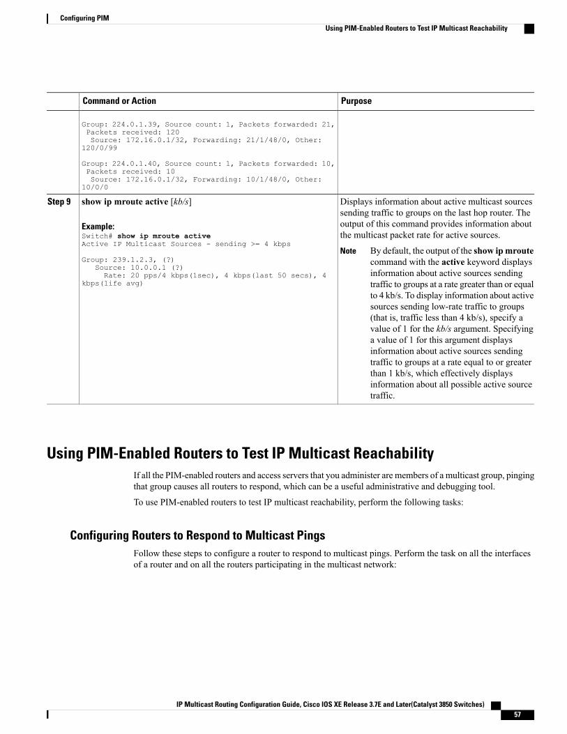
PurposeCommand or Action
Group: 224.0.1.39, Source count: 1, Packets forwarded: 21,Packets received: 120Source: 172.16.0.1/32, Forwarding: 21/1/48/0, Other:
120/0/99
Group: 224.0.1.40, Source count: 1, Packets forwarded: 10,Packets received: 10Source: 172.16.0.1/32, Forwarding: 10/1/48/0, Other:
10/0/0
Displays information about active multicast sourcessending traffic to groups on the last hop router. The
show ip mroute active [kb/s]
Example:Switch# show ip mroute activeActive IP Multicast Sources - sending >= 4 kbps
Step 9
output of this command provides information aboutthe multicast packet rate for active sources.
By default, the output of the show ipmroutecommand with the active keyword displaysinformation about active sources sendingtraffic to groups at a rate greater than or equalto 4 kb/s. To display information about activesources sending low-rate traffic to groups(that is, traffic less than 4 kb/s), specify avalue of 1 for the kb/s argument. Specifyinga value of 1 for this argument displaysinformation about active sources sendingtraffic to groups at a rate equal to or greaterthan 1 kb/s, which effectively displaysinformation about all possible active sourcetraffic.
NoteGroup: 239.1.2.3, (?)
Source: 10.0.0.1 (?)Rate: 20 pps/4 kbps(1sec), 4 kbps(last 50 secs), 4
kbps(life avg)
Using PIM-Enabled Routers to Test IP Multicast ReachabilityIf all the PIM-enabled routers and access servers that you administer are members of a multicast group, pingingthat group causes all routers to respond, which can be a useful administrative and debugging tool.
To use PIM-enabled routers to test IP multicast reachability, perform the following tasks:
Configuring Routers to Respond to Multicast PingsFollow these steps to configure a router to respond to multicast pings. Perform the task on all the interfacesof a router and on all the routers participating in the multicast network:
IP Multicast Routing Configuration Guide, Cisco IOS XE Release 3.7E and Later(Catalyst 3850 Switches) 57
Configuring PIMUsing PIM-Enabled Routers to Test IP Multicast Reachability

SUMMARY STEPS
1. enable2. configure terminal3. interface type number4. ip igmp join-group group-address5. Repeat Step 3 and Step 4 for each interface on the router participating in the multicast network.6. end
DETAILED STEPS
PurposeCommand or Action
Enables privileged EXECmode. Enter your password if prompted.enable
Example:
Switch> enable
Step 1
Enters global configuration mode.configure terminal
Example:
Switch# configure terminal
Step 2
Enters interface configuration mode.interface type numberStep 3
Example:
Switch(config)# interface gigabitethernet1/0/0
For the type and number arguments, specify an interface that isdirectly connected to hosts or is facing hosts.
(Optional) Configures an interface on the router to join the specifiedgroup.
ip igmp join-group group-address
Example:
Switch(config-if)# ip igmp join-group225.2.2.2
Step 4
For the purpose of this task, configure the same group address forthe group-address argument on all interfaces on the routerparticipating in the multicast network.
With this method, the router accepts the multicast packetsin addition to forwarding them. Accepting the multicastpackets prevents the router from fast switching.
Note
--Repeat Step 3 and Step 4 for each interface onthe router participating in the multicast network.
Step 5
Ends the current configuration session and returns to privilegedEXEC mode.
end
Example:
Switch(config-if)# end
Step 6
IP Multicast Routing Configuration Guide, Cisco IOS XE Release 3.7E and Later(Catalyst 3850 Switches)58
Configuring PIMUsing PIM-Enabled Routers to Test IP Multicast Reachability
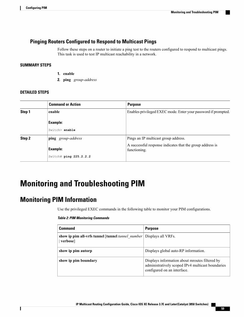
Pinging Routers Configured to Respond to Multicast PingsFollow these steps on a router to initiate a ping test to the routers configured to respond to multicast pings.This task is used to test IP multicast reachability in a network.
SUMMARY STEPS
1. enable2. ping group-address
DETAILED STEPS
PurposeCommand or Action
Enables privileged EXECmode. Enter your password if prompted.enable
Example:
Switch> enable
Step 1
Pings an IP multicast group address.ping group-addressStep 2
Example:
Switch# ping 225.2.2.2
A successful response indicates that the group address isfunctioning.
Monitoring and Troubleshooting PIM
Monitoring PIM InformationUse the privileged EXEC commands in the following table to monitor your PIM configurations.
Table 2: PIM Monitoring Commands
PurposeCommand
Displays all VRFs.show ip pim all-vrfs tunnel [tunnel tunnel_number| verbose]
Displays global auto-RP information.show ip pim autorp
Displays information about mroutes filtered byadministratively scoped IPv4 multicast boundariesconfigured on an interface.
show ip pim boundary
IP Multicast Routing Configuration Guide, Cisco IOS XE Release 3.7E and Later(Catalyst 3850 Switches) 59
Configuring PIMMonitoring and Troubleshooting PIM

PurposeCommand
Displays information about interfaces configured forProtocol Independent Multicast (PIM).
show ip pim interface
Displays the PIM neighbor information.show ip pim neighbor
Displays RP routers associated with a sparse-modemulticast group. This command is available in allsoftware images.
show ip pim rp[group-name | group-address]
Displays information about Protocol IndependentMulticast (PIM) tunnel interfaces
show ip pim tunnel [tunnel | verbose]
Displays the VPN routing/forwarding instance.show ip pim vrf { word { all-vrfs | autorp |boundary | bsr-router | interface |mdt | neighbor| rp | rp-hash | tunnel } }
Displays the interested clients that have joined thespecific multicast source group.
show ip igmp groups detail
Monitoring the RP Mapping and BSR InformationUse the privileged EXEC mode in the following table to verify the consistency of group-to-RP mappings:
Table 3: RP Mapping Monitoring Commands
PurposeCommand
Displays all available RP mappings and metrics. This tellsyou how the switch learns of the RP (through the BSR or theAuto-RP mechanism).
• (Optional) For the hostname, specify the IP name of thegroup about which to display RPs.
• (Optional) For the IP address, specify the IP address ofthe group about which to display RPs.
• (Optional) Use themapping keyword to display allgroup-to-RP mappings of which the Cisco device isaware (either configured or learned from Auto-RP).
• (Optional) Use themetric keyword to display the RPRPF metric.
show ip pim rp [ hostname or IP address |mapping [ hostname or IP address | elected| in-use ] |metric [ hostname or IP address] ]
Displays the RP that was selected for the specified group. Thatis, on a PIMv2 router or multilayer switch, confirms that thesame RP is the one that a PIMv1 system chooses. For group,enter the group address for which to display RP information.
show ip pim rp-hash group
IP Multicast Routing Configuration Guide, Cisco IOS XE Release 3.7E and Later(Catalyst 3850 Switches)60
Configuring PIMMonitoring the RP Mapping and BSR Information

Use the privileged EXEC commands in the following table to monitor BSR information:
Table 4: BSR Monitoring Commands
PurposeCommand
Displays information about the elected BSR.show ip pim bsr
Displays information about the BSRv2.show ip pim bsr-router
Troubleshooting PIMv1 and PIMv2 Interoperability ProblemsWhen debugging interoperability problems between PIMv1 and PIMv2, check these in the order shown:
1 Verify RP mapping with the show ip pim rp-hash privileged EXEC command, making sure that allsystems agree on the same RP for the same group.
2 Verify interoperability between different versions of DRs and RPs. Make sure that the RPs are interactingwith the DRs properly (by responding with register-stops and forwarding decapsulated data packets fromregisters).
Related Topics
PIM Versions, on page 7
Configuration Examples for PIM
Example: Enabling PIM Stub RoutingIn this example, IP multicast routing is enabled, Switch A PIM uplink port 25 is configured as a routed uplinkport with spare-dense-mode enabled. PIM stub routing is enabled on the VLAN 100 interfaces and on GigabitEthernet port 20.
Switch(config)# ip multicast-routing distributedSwitch(config)# interface GigabitEthernet3/0/25Switch(config-if)# no switchportSwitch(config-if)# ip address 3.1.1.2 255.255.255.0Switch(config-if)# ip pim sparse-dense-modeSwitch(config-if)# exitSwitch(config)# interface vlan100Switch(config-if)# ip pim passiveSwitch(config-if)# exitSwitch(config)# interface GigabitEthernet3/0/20Switch(config-if)# ip pim passiveSwitch(config-if)# exitSwitch(config)# interface vlan100Switch(config-if)# ip address 100.1.1.1 255.255.255.0Switch(config-if)# ip pim passiveSwitch(config-if)# exitSwitch(config)# interface GigabitEthernet3/0/20
IP Multicast Routing Configuration Guide, Cisco IOS XE Release 3.7E and Later(Catalyst 3850 Switches) 61
Configuring PIMTroubleshooting PIMv1 and PIMv2 Interoperability Problems

Switch(config-if)# no switchportSwitch(config-if)# ip address 10.1.1.1 255.255.255.0Switch(config-if)# ip pim passiveSwitch(config-if)# end
Related Topics
Enabling PIM Stub Routing (CLI), on page 21
PIM Stub Routing, on page 8
Example: Verifying PIM Stub RoutingTo verify that PIM stub is enabled for each interface, use the show ip pim interface privileged EXECcommand:
Switch# show ip pim interfaceAddress Interface Ver/ Nbr Query DR DRMode Count Intvl Prior3.1.1.2 GigabitEthernet3/0/25 v2/SD 1 30 1 3.1.1.2100.1.1.1 Vlan100 v2/P 0 30 1 100.1.1.110.1.1.1 GigabitEthernet3/0/20 v2/P 0 30 1 10.1.1.1
Related Topics
Enabling PIM Stub Routing (CLI), on page 21
PIM Stub Routing, on page 8
Example: Manually Assigning an RP to Multicast GroupsThis example shows how to configure the address of the RP to 147.106.6.22 for multicast group 225.2.2.2only:
Switch(config)# access-list 1 permit 225.2.2.2 0.0.0.0Switch(config)# ip pim rp-address 147.106.6.22 1
Related Topics
Manually Assigning an RP to Multicast Groups (CLI), on page 24
Example: Configuring Auto-RPThis example shows how to send RP announcements out all PIM-enabled interfaces for a maximum of 31hops. The IP address of port 1 is the RP. Access list 5 describes the group for which this switch serves as RP:
Switch(config)# ip pim send-rp-announce gigabitethernet1/0/1 scope 31 group-list 5Switch(config)# access-list 5 permit 224.0.0.0 15.255.255.255
Related Topics
Setting Up Auto-RP in a New Internetwork (CLI), on page 26
IP Multicast Routing Configuration Guide, Cisco IOS XE Release 3.7E and Later(Catalyst 3850 Switches)62
Configuring PIMExample: Verifying PIM Stub Routing

Auto-RP, on page 10
Example: Sparse Mode with Auto-RPThe following example configures sparse mode with Auto-RP:
ip multicast-routingip pim autorp listenerip pim send-rp-announce Loopback0 scope 16 group-list 1ip pim send-rp-discovery Loopback1 scope 16no ip pim dm-fallbackaccess-list 1 permit 239.254.2.0 0.0.0.255access-list 1 permit 239.254.3.0 0.0.0.255...access-list 10 permit 224.0.1.39access-list 10 permit 224.0.1.40access-list 10 permit 239.254.2.0 0.0.0.255access-list 10 permit 239.254.3.0 0.0.0.255
Related Topics
Setting Up Auto-RP in a New Internetwork (CLI), on page 26
Auto-RP, on page 10
Example: Defining the IP Multicast Boundary to Deny Auto-RP InformationThis example shows a portion of an IP multicast boundary configuration that denies Auto-RP information:
Switch(config)# access-list 1 deny 224.0.1.39Switch(config)# access-list 1 deny 224.0.1.40Switch(config)# access-list 1 permit allSwitch(config)# interface gigabitethernet1/0/1Switch(config-if)# ip multicast boundary 1
Related Topics
Defining the IP Multicast Boundary (CLI), on page 36
Multicast Boundaries, on page 11
Example: Filtering Incoming RP Announcement MessagesThis example shows a sample configuration on an Auto-RP mapping agent that is used to prevent candidateRP announcements from being accepted from unauthorized candidate RPs:
Switch(config)# ip pim rp-announce-filter rp-list 10 group-list 20Switch(config)# access-list 10 permit host 172.16.5.1Switch(config)# access-list 10 permit host 172.16.2.1Switch(config)# access-list 20 deny 239.0.0.0 0.0.255.255Switch(config)# access-list 20 permit 224.0.0.0 15.255.255.255
The mapping agent accepts candidate RP announcements from only two devices, 172.16.5.1 and 172.16.2.1.The mapping agent accepts candidate RP announcements from these two devices only for multicast groupsthat fall in the group range of 224.0.0.0 to 239.255.255.255. The mapping agent does not accept candidate
IP Multicast Routing Configuration Guide, Cisco IOS XE Release 3.7E and Later(Catalyst 3850 Switches) 63
Configuring PIMExample: Sparse Mode with Auto-RP

RP announcements from any other devices in the network. Furthermore, the mapping agent does not acceptcandidate RP announcements from 172.16.5.1 or 172.16.2.1 if the announcements are for any groups in the239.0.0.0 through 239.255.255.255 range. This range is the administratively scoped address range.
Related Topics
Filtering Incoming RP Announcement Messages (CLI), on page 32
Example: Preventing Join Messages to False RPsIf all interfaces are in sparse mode, use a default-configured RP to support the two well-knowngroups 224.0.1.39 and 224.0.1.40. Auto-RP uses these two well-known groups to collect and distributeRP-mapping information. When this is the case and the ip pim accept-rp auto-rp command is configured,another ip pim accept-rp command accepting the RP must be configured as follows:
Switch(config)# ip pim accept-rp 172.10.20.1 1Switch(config)# access-list 1 permit 224.0.1.39Switch(config)# access-list 1 permit 224.0.1.40
Related Topics
Preventing Join Messages to False RPs (CLI), on page 32
Example: Configuring Candidate BSRsThis example shows how to configure a candidate BSR, which uses the IP address 172.21.24.18 on a port asthe advertised BSR address, uses 30 bits as the hash-mask-length, and has a priority of 10.
Switch(config)# interface gigabitethernet1/0/2Switch(config-if)# ip address 172.21.24.18 255.255.255.0Switch(config-if)# ip pim sparse-dense-modeSwitch(config-if)# ip pim bsr-candidate gigabitethernet1/0/2 30 10
Related Topics
Configuring Candidate BSRs (CLI), on page 39
PIMv2 Bootstrap Router, on page 13
Example: Configuring Candidate RPsThis example shows how to configure the switch to advertise itself as a candidate RP to the BSR in its PIMdomain. Standard access list number 4 specifies the group prefix associated with the RP that has the addressidentified by a port. That RP is responsible for the groups with the prefix 239.
Switch(config)# ip pim rp-candidate gigabitethernet1/0/2 group-list 4Switch(config)# access-list 4 permit 239.0.0.0 0.255.255.255
Related Topics
Configuring the Candidate RPs (CLI), on page 40
IP Multicast Routing Configuration Guide, Cisco IOS XE Release 3.7E and Later(Catalyst 3850 Switches)64
Configuring PIMExample: Preventing Join Messages to False RPs

Rendezvous Points, on page 9
Additional ReferencesRelated Documents
Document TitleRelated Topic
IP Multicast Routing Command Reference (Catalyst3850 Switches)
For complete syntax and usage information for thecommands used in this chapter.
IP Multicast Routing Command Reference (Catalyst3850 Switches)
IGMP Helper command syntax and usageinformation.
IP Routing: Protocol-Independent ConfigurationGuide,Cisco IOS XE Release 3E (Catalyst 3850 Switches)
Multicast Source Discovery Protocol (MSDP)
IP Routing: EIGRP Configuration Guide, Cisco IOSXE Release 3E (Catalyst 3850 Switches)
Enhanced Interior Gateway Routing Protocol(EIGRP) stub routing
IP Routing: OSPF Configuration Guide, Cisco IOS XE3E (Catalyst 3850 Switches)
Open Shortest Path First (OSPF) stub routing
Cisco IOS Master Commands List, All ReleasesCisco IOS commands
Cisco IOS IP Multicast Command ReferenceCisco IOS IP SLAs commands
Error Message Decoder
LinkDescription
https://www.cisco.com/cgi-bin/Support/Errordecoder/index.cgi
To help you research and resolve system errormessages in this release, use the Error MessageDecoder tool.
IP Multicast Routing Configuration Guide, Cisco IOS XE Release 3.7E and Later(Catalyst 3850 Switches) 65
Configuring PIMAdditional References

Standards and RFCs
TitleStandard/RFC
• Protocol Independent Multicast (PIM):Motivation and Architecture
• Protocol Independent Multicast (PIM), DenseMode Protocol Specification
• Protocol Independent Multicast (PIM), SparseMode Protocol Specification
• draft-ietf-idmr-igmp-v2-06.txt, Internet GroupManagement Protocol, Version 2
• draft-ietf-pim-v2-dm-03.txt, PIM Version 2Dense Mode
PIM is defined in RFC 4601 and in these InternetEngineering Task Force (IETF) Internet drafts.
MIBs
MIBs LinkMIB
To locate and downloadMIBs for selected platforms,Cisco IOS releases, and feature sets, use Cisco MIBLocator found at the following URL:
http://www.cisco.com/go/mibs
All supported MIBs for this release.
Technical Assistance
LinkDescription
http://www.cisco.com/supportThe Cisco Support website provides extensive onlineresources, including documentation and tools fortroubleshooting and resolving technical issues withCisco products and technologies.
To receive security and technical information aboutyour products, you can subscribe to various services,such as the Product Alert Tool (accessed from FieldNotices), the Cisco Technical Services Newsletter,and Really Simple Syndication (RSS) Feeds.
Access to most tools on the Cisco Support websiterequires a Cisco.com user ID and password.
IP Multicast Routing Configuration Guide, Cisco IOS XE Release 3.7E and Later(Catalyst 3850 Switches)66
Configuring PIMAdditional References

Feature History and Information for PIMModificationRelease
This feature was introduced.Cisco IOS XE 3.2SE
IP Multicast Routing Configuration Guide, Cisco IOS XE Release 3.7E and Later(Catalyst 3850 Switches) 67
Configuring PIMFeature History and Information for PIM

IP Multicast Routing Configuration Guide, Cisco IOS XE Release 3.7E and Later(Catalyst 3850 Switches)68
Configuring PIMFeature History and Information for PIM