Embed Size (px)
Citation preview
Configuring Fabric Basics and Layer 2Services for VOSS
Release 8.1 (VOSS)9035880 Rev ABNovember 2019

© 2017-2019, Extreme Networks, Inc.All Rights Reserved.
Legal NoticeExtreme Networks, Inc. reserves the right to make changes inspecifications and other information contained in this document andits website without prior notice. The reader should in all cases consultrepresentatives of Extreme Networks to determine whether any suchchanges have been made.The hardware, firmware, software or any specifications described orreferred to in this document are subject to change without notice.TrademarksExtreme Networks and the Extreme Networks logo are trademarks orregistered trademarks of Extreme Networks, Inc. in the United Statesand/or other countries.All other names (including any product names) mentioned in thisdocument are the property of their respective owners and may betrademarks or registered trademarks of their respective companies/owners.For additional information on Extreme Networks trademarks, pleasesee: www.extremenetworks.com/company/legal/trademarksOpen Source DeclarationsSome software files have been licensed under certain open source orthird-party licenses. End-user license agreements and open sourcedeclarations can be found at: www.extremenetworks.com/support/policies/software-licensing

Contents
Chapter 1: About this Document............................................................................................. 7Purpose.................................................................................................................................. 7Conventions............................................................................................................................ 7
Text Conventions............................................................................................................... 8Documentation and Training................................................................................................... 10Getting Help.......................................................................................................................... 10Providing Feedback to Us...................................................................................................... 11
Chapter 2: New in this Document.......................................................................................... 12Notice about Feature Support................................................................................................. 13
Chapter 3: SPBM and IS-IS configuration workflow............................................................ 14Chapter 4: SPBM and IS-IS infrastructure configuration.................................................... 16
SPBM and IS-IS infrastructure fundamentals........................................................................... 16advanced-feature-bandwidth-reservation Boot Flag............................................................ 19spbm-config-mode boot flag............................................................................................. 21vxlan-gw-full-interworking-mode boot flag.......................................................................... 21MAC-in-MAC encapsulation............................................................................................. 22I-SID.............................................................................................................................. 22BCBs and BEBs.............................................................................................................. 23VLANs without member ports........................................................................................... 24Basic SPBM network topology.......................................................................................... 25E-Tree and Private VLAN topology................................................................................... 26IS-IS............................................................................................................................... 27Standard TLVs................................................................................................................ 29IS-IS hierarchies.............................................................................................................. 32IS-IS PDUs..................................................................................................................... 32IS-IS configuration parameters......................................................................................... 32SPBM B-VLAN................................................................................................................ 35Pre-populated FIB........................................................................................................... 36RPFC............................................................................................................................. 36SPBM FIB....................................................................................................................... 37SPBM restrictions and limitations...................................................................................... 38Network Load Balancing (NLB) ........................................................................................ 40SPBM script.................................................................................................................... 41Layer 2 Video Surveillance install script............................................................................. 42Fabric Extend.................................................................................................................. 44Fabric Attach................................................................................................................... 63Endpoint Tracking........................................................................................................... 81IS-IS external metric........................................................................................................ 85SPB Ethertype ............................................................................................................... 85
November 2019 Configuring Fabric Basics and Layer 2 Services for VOSS 3

Zero Touch Fabric Configuration....................................................................................... 86FAN Transit..................................................................................................................... 89Dynamic Nickname Assignment....................................................................................... 90MSTP-Fabric Connect Multi Homing................................................................................. 93
SPBM and IS-IS infrastructure configuration using CLI............................................................. 94Running the SPBM script................................................................................................. 94Removing existing SPBM configuration............................................................................. 95Configuring the IS-IS port interfaces using SPBM script...................................................... 96Removing specific IS-IS and MLT interfaces...................................................................... 97Configuring minimum SPBM and IS-IS parameters............................................................ 98Configuring minimum SPBM and IS-IS parameters using auto-nni command..................... 103Configuring I-SIDs for private VLANs.............................................................................. 106Displaying global SPBM parameters............................................................................... 107Displaying global IS-IS parameters................................................................................. 109Displaying IS-IS areas.................................................................................................... 112Configuring SMLT parameters for SPBM......................................................................... 112Configuring optional SPBM parameters........................................................................... 114Configuring optional IS-IS global parameters................................................................... 117Configuring optional IS-IS interface parameters............................................................... 121Displaying IS-IS interface parameters............................................................................. 124Displaying the IP unicast FIB, multicast FIB, unicast FIB, and unicast tree......................... 126Displaying IS-IS LSDB and adjacencies.......................................................................... 132Displaying IS-IS Statistics and Counters.......................................................................... 136Running the Layer 2 Video Surveillance install script........................................................ 138Fabric Extend configuration using the CLI....................................................................... 140Fabric Attach configuration using the CLI........................................................................ 153Configure Endpoint Tracking Using CLI........................................................................... 183IS-IS external metric configuration using the CLI.............................................................. 188Suspending duplicate system ID detection when replacing a switch................................... 192Configuring a Dynamic Nickname Assignment nickname allocation range.......................... 193Displaying Dynamic Nickname Assignment..................................................................... 194Enabling MSTP-Fabric Connect Multi Homing................................................................. 194Determine the Root Bridge in an MSTP-Fabric Connect Multi Homing Configuration .......... 195
SPBM and IS-IS infrastructure configuration using EDM......................................................... 196Configuring required SPBM and IS-IS parameters............................................................ 196Displaying SPBM and IS-IS summary information............................................................ 200Displaying the SPBM I-SID information........................................................................... 201Displaying Level 1 Area information................................................................................ 202Configuring SMLT parameters for SPBM......................................................................... 202Enabling or disabling SPBM at the global level................................................................ 203Configuring SPBM parameters....................................................................................... 204Displaying SPBM nicknames.......................................................................................... 205Configuring interface SPBM parameters.......................................................................... 206
Contents
November 2019 Configuring Fabric Basics and Layer 2 Services for VOSS 4

Configuring SPBM on an interface.................................................................................. 207Displaying the IP unicast FIB.......................................................................................... 207Displaying the IPv6 unicast FIB...................................................................................... 208Displaying the unicast FIB.............................................................................................. 209Displaying LSP summary information.............................................................................. 210Displaying IS-IS adjacencies.......................................................................................... 211Configuring IS-IS global parameters............................................................................... 212Configuring system-level IS-IS parameters...................................................................... 214Displaying IS-IS system statistics.................................................................................... 215Configuring IS-IS interfaces............................................................................................ 216Configuring IS-IS interface level parameters.................................................................... 218Displaying IS-IS interface counters................................................................................. 219Displaying IS-IS interface control packets........................................................................ 220Graphing IS-IS interface counters................................................................................... 221Graphing IS-IS interface sending control packet statistics................................................. 222Graphing IS-IS interface receiving control packet statistics............................................... 223Configuring an IS-IS Manual Area................................................................................... 224Fabric Extend configuration using EDM........................................................................... 224Fabric Attach configuration using the EDM...................................................................... 230Configure Endpoint Tracking Using EDM......................................................................... 247Configuring Dynamic Nickname Assignment.................................................................... 250
SPBM configuration examples.............................................................................................. 251Basic SPBM configuration example................................................................................ 251Ethernet and MLT configuration...................................................................................... 252IS-IS SPBM global configuration..................................................................................... 252IS-IS SPBM Interface Configuration................................................................................ 254Verifying SPBM operations............................................................................................. 255
Fabric Extend configuration examples................................................................................... 257Fabric Extend over IP using the GRT.............................................................................. 257Fabric Extend over IP using a VRF................................................................................. 261Fabric Extend over VPLS............................................................................................... 263Fabric Extend over Layer 2 Pseudowire.......................................................................... 266Fabric Extend with ONAs in the core and branches.......................................................... 268Fabric Extend Over IPsec.............................................................................................. 271
Fabric Attach configuration examples.................................................................................... 272Configuring a Fabric Attach solution................................................................................ 272Configuring Fabric Attach in an SMLT ............................................................................ 277
Chapter 5: Layer 2 VSN configuration................................................................................ 287Layer 2 VSN configuration fundamentals............................................................................... 288
SPBM L2 VSN.............................................................................................................. 288SPBM sample operation—L2 VSN.................................................................................. 297
Layer 2 VSN configuration using the CLI............................................................................... 303Configuring SPBM Layer 2 VSN..................................................................................... 303
Contents
November 2019 Configuring Fabric Basics and Layer 2 Services for VOSS 5

Displaying C-VLAN I-SID information.............................................................................. 304Configuring an SPBM Layer 2 Transparent Port UNI........................................................ 308Viewing all Configured I-SIDs......................................................................................... 310Viewing C-MACs Learned on T-UNI Ports for an I-SID...................................................... 313Viewing I-SID maximum MAC-limit.................................................................................. 316Configuring an SPBM Layer 2 Switched UNI on an MLT................................................... 317Configuring an SPBM Layer 2 Switched UNI on a Port..................................................... 319Viewing all configured Switched UNI I-SIDs..................................................................... 321Displaying C-VLAN and Switched UNI I-SID information................................................... 324
Layer 2 VSN configuration using EDM.................................................................................. 328Configuring SPBM Layer 2 VSN..................................................................................... 328Displaying the remote MAC table for a C-VLAN............................................................... 329Configuring UNI............................................................................................................ 330Associating a port and MLT with an ISID for Elan Transparent.......................................... 331Viewing the ISID forwarding database............................................................................. 332Associating a port and MLT with an I-SID for Elan............................................................ 333Viewing the I-SID interface............................................................................................. 334
Layer 2 VSN configuration examples.................................................................................... 334Layer 2 VSN configuration example................................................................................ 334Verifying Layer 2 VSN operation..................................................................................... 335Layer 2 VSN example with VLAN ID translation............................................................... 337
Chapter 6: Inter-VSN Routing Configuration...................................................................... 339Inter-VSN routing configuration fundamentals........................................................................ 339
Inter-VSN routing.......................................................................................................... 339Inter-VSN routing configuration using the CLI........................................................................ 340
Configuring SPBM Inter-VSN Routing............................................................................. 340Inter-VSN routing configuration using EDM............................................................................ 343
Configuring BEBs for Inter-VSN routing........................................................................... 343Configuring BCBs for Inter-VSN routing........................................................................... 348
Inter-VSN routing configuration example............................................................................... 354Inter-VSN routing with SPBM configuration example........................................................ 354Verifying Inter-VSN Routing operation............................................................................. 355
Appendix A: SPBM Reference Architectures..................................................................... 357Reference architectures....................................................................................................... 357
Campus Architecture..................................................................................................... 359Large data center architecture........................................................................................ 362
Solution-specific reference architectures............................................................................... 367Glossary................................................................................................................................. 373
Contents
November 2019 Configuring Fabric Basics and Layer 2 Services for VOSS 6
Chapter 1: About this Document
This section discusses the purpose of this document, the conventions used, ways to providefeedback, additional help, and information regarding other Extreme Networks publications.
PurposeThis document provides information on features in VSP Operating System Software (VOSS). VOSSruns on the following product families:
• Extreme Networks VSP 4000 Series (includes VSP 4450 Series)
• Extreme Networks VSP 4900 Series
• Extreme Networks VSP 7200 Series
• Extreme Networks VSP 7400 Series
• Extreme Networks VSP 8000 Series (includes VSP 8200 Series and VSP 8400 Series)
• Extreme Networks VSP 8600 Series
• Extreme Networks XA1400 Series
Note:
VOSS is licensed on the XA1400 Series as a Fabric Connect VPN (FCVPN) application,which includes a subset of VOSS features. FCVPN transparently extends Fabric Connectservices over third-party provider networks.
This document provides information and instructions to configure Fabric basics and Layer 2 serviceson the switch.
ConventionsThis section discusses the conventions used in this guide.
November 2019 Configuring Fabric Basics and Layer 2 Services for VOSS 7

Text ConventionsThe following tables list text conventions that can be used throughout this document.
Table 1: Notice Icons
Icon Alerts you to...
Important: A situation that can cause serious inconvenience.
Note: Important features or instructions.
Tip: Helpful tips and notices for using the product.
Danger: Situations that will result in severe bodily injury; up toand including death.
Warning: Risk of severe personal injury or critical loss of data.
Caution: Risk of personal injury, system damage, or loss ofdata.
Table 2: Text Conventions
Convention DescriptionAngle brackets ( < > ) Angle brackets ( < > ) indicate that you choose the
text to enter based on the description inside thebrackets. Do not type the brackets when you enterthe command.
If the command syntax is cfm maintenance-domain maintenance-level <0-7> , you canenter cfm maintenance-domainmaintenance-level 4.
Bold text Bold text indicates the GUI object name you must actupon.
Examples:
• Click OK.
• On the Tools menu, choose Options.Braces ( { } ) Braces ( { } ) indicate required elements in syntax
descriptions. Do not type the braces when you enterthe command.
For example, if the command syntax is ip address{A.B.C.D}, you must enter the IP address indotted, decimal notation.
Table continues…
About this Document
November 2019 Configuring Fabric Basics and Layer 2 Services for VOSS 8

Convention DescriptionBrackets ( [ ] ) Brackets ( [ ] ) indicate optional elements in syntax
descriptions. Do not type the brackets when youenter the command.
For example, if the command syntax is show clock[detail], you can enter either show clock orshow clock detail.
Ellipses ( … ) An ellipsis ( … ) indicates that you repeat the lastelement of the command as needed.
For example, if the command syntax isethernet/2/1 [ <parameter><value> ]..., you enter ethernet/2/1 and asmany parameter-value pairs as you need.
Italic Text Italics emphasize a point or denote new terms at theplace where they are defined in the text. Italics arealso used when referring to publication titles that arenot active links.
Plain Courier Text Plain Courier text indicates command names,options, and text that you must enter. Plain Couriertext also indicates command syntax and systemoutput, for example, prompts and system messages.
Examples:
• show ip route• Error: Invalid command syntax[Failed][2013-03-22 13:37:03.303-04:00]
Separator ( > ) A greater than sign ( > ) shows separation in menupaths.
For example, in the Navigation tree, expand theConfiguration > Edit folders.
Vertical Line ( | ) A vertical line ( | ) separates choices for commandkeywords and arguments. Enter only one choice. Donot type the vertical line when you enter thecommand.
For example, if the command syntax is access-policy by-mac action { allow | deny } ,you enter either access-policy by-mac actionallow or access-policy by-mac actiondeny, but not both.
Conventions
November 2019 Configuring Fabric Basics and Layer 2 Services for VOSS 9

Documentation and TrainingFind Extreme Networks product information at the following locations:
Current Product DocumentationArchived Documentation (for earlier versions and legacy products)Release NotesHardware/software compatibility matrices for Campus and Edge productsSupported transceivers and cables for Data Center productsOther resources, like white papers, data sheets, and case studies
Extreme Networks offers product training courses, both online and in person, as well as specializedcertifications. For details, visit www.extremenetworks.com/education/.
Getting HelpIf you require assistance, contact Extreme Networks using one of the following methods:
ExtremePortal
Search the GTAC (Global Technical Assistance Center) knowledge base, managesupport cases and service contracts, download software, and obtain productlicensing, training, and certifications.
The Hub A forum for Extreme Networks customers to connect with one another, answerquestions, and share ideas and feedback. This community is monitored by ExtremeNetworks employees, but is not intended to replace specific guidance from GTAC.
Call GTAC For immediate support: 1-800-998-2408 (toll-free in U.S. and Canada) or +1408-579-2826. For the support phone number in your country, visit: www.extremenetworks.com/support/contact
Before contacting Extreme Networks for technical support, have the following information ready:
• Your Extreme Networks service contract number and/or serial numbers for all involved ExtremeNetworks products
• A description of the failure
• A description of any action(s) already taken to resolve the problem
• A description of your network environment (such as layout, cable type, other relevantenvironmental information)
• Network load at the time of trouble (if known)
• The device history (for example, if you have returned the device before, or if this is a recurringproblem)
• Any related RMA (Return Material Authorization) numbers
About this Document
November 2019 Configuring Fabric Basics and Layer 2 Services for VOSS 10

Subscribing to Service NotificationsYou can subscribe to email notifications for product and software release announcements,Vulnerability Notices, and Service Notifications.
1. Go to www.extremenetworks.com/support/service-notification-form.2. Complete the form with your information (all fields are required).3. Select the products for which you would like to receive notifications.
Note:You can modify your product selections or unsubscribe at any time.
4. Click Submit.
Providing Feedback to UsQuality is our first concern at Extreme Networks, and we have made every effort to ensure theaccuracy and completeness of this document. We are always striving to improve our documentationand help you work better, so we want to hear from you! We welcome all feedback but especiallywant to know about:
• Content errors or confusing or conflicting information.
• Ideas for improvements to our documentation so you can find the information you need faster.
• Broken links or usability issues.
If you would like to provide feedback to the Extreme Networks Information Development team, youcan do so in two ways:
• Use our short online feedback form at https://www.extremenetworks.com/documentation-feedback/.
• Email us at [email protected].
Please provide the publication title, part number, and as much detail as possible, including the topicheading and page number if applicable, as well as your suggestions for improvement.
Providing Feedback to Us
November 2019 Configuring Fabric Basics and Layer 2 Services for VOSS 11

Chapter 2: New in this Document
The following sections detail what is new in this document.
Endpoint TrackingNote:DEMO FEATURE - Endpoint Tracking is a demonstration feature. Demonstration features areprovided for testing purposes. Demonstration features are for lab use only and are not for use ina production environment.
This release adds support for Endpoint Tracking, which provides dynamic assignment of virtualmachines (VMs) to IP subnets as they move within a Shortest Path Bridging (SPB) cloud. ExtremeManagement Center is integral to the Endpoint Tracking solution. Extreme Management Center'sExtremeConnect module integrates with third-party virtualization software (such as VMware orMicrosoft HyperV) and communicates with the ExtremeControl module, which provides the RADIUSauthentication functionality.For more information, see:
• Endpoint Tracking on page 81• Configure Endpoint Tracking Using CLI on page 183• Configure Endpoint Tracking Using EDM on page 247
MSTP-Fabric Connect Multi HomingDetermine the Root Bridge in an MSTP-Fabric Connect Multi Homing Configuration on page 195 isadded to the document.
Zero Touch Fabric Configuration ModificationsZero Touch Fabric Configuration is modified in the following ways:
• The manual area changed from 00.0000.0000 to 00.1515.fee1.900d.1515.fee1.900d.• You can change the manual area dynamically, without disabling IS-IS, only when the area is
the Zero Touch Fabric Configuration area.• When IS-IS is enabled, you cannot delete the last manual area.
For more information, see Zero Touch Fabric Configuration on page 86.The manual area modifications impact upgrades from earlier releases. For more information, see Administering VOSS.
November 2019 Configuring Fabric Basics and Layer 2 Services for VOSS 12

Notice about Feature SupportThis document includes content for multiple hardware platforms across different software releases.As a result, the content can include features not supported by your hardware in the current softwarerelease.
If a documented command, parameter, tab, or field does not appear on your hardware, it is notsupported.
For information about physical hardware restrictions, see your hardware documentation.
Notice about Feature Support
November 2019 Configuring Fabric Basics and Layer 2 Services for VOSS 13

Chapter 3: SPBM and IS-IS configurationworkflow
The following section describes the generic work flow to configure SPBM and IS-IS infrastructureand services on your network.
Note:This section is an overview. For further details on the SPBM and IS-IS infrastructure andconfiguration, see the documents described in the Documentation sources section below.1. Infrastructure configuration
As a first step, you must configure your basic infrastructure for Shortest Path Bridging MAC(SPBM).
2. Services configurationAfter you complete the infrastructure configuration, you configure the appropriate services foryour network to run on top of your base architecture. This includes:• Layer 2 and Layer 3 VSNs• IP Shortcuts• Inter-VSN routing
3. Fabric interoperationsYou can also configure Fabric gateway functionality like SPB-PIM Gateway and VXLANGateway.
4. Operations and ManagementTo debug connectivity issues and isolate network faults in the SPBM network, you can useConnectivity Fault Management (CFM).
Documentation SourcesRefer to the following documentation sources:
• For information on basic SPBM infrastructure and IS-IS configuration and Layer 2 services, see Configuring Fabric Basics and Layer 2 Services for VOSS.This document also contains information on configuring Fabric Extend, which enables yourenterprise to extend Fabric Connect technology over Layer 2 or Layer 3 core networks.
• For information on Fabric Layer 3 services configuration, see Configuring Fabric Layer 3Services for VOSS.
• For information on IP Multicast over Fabric Connect configuration and services, see Configuring Fabric Multicast Services for VOSS. This document also contains information
November 2019 Configuring Fabric Basics and Layer 2 Services for VOSS 14

about configuring the SPB-PIM Gateway (SPB-PIM GW), which provides multicast inter-domain communication between an SPB network and a PIM network. The SPB-PIM GW canalso connect two independent SPB domains.
• For information on CFM, see Troubleshooting VOSS.• For information on VXLAN Gateway configuration, see Configuring VXLAN Gateway for VOSS.
November 2019 Configuring Fabric Basics and Layer 2 Services for VOSS 15

Chapter 4: SPBM and IS-IS infrastructureconfiguration
This chapter provides concepts and procedures to configure the basic infrastructure for ShortestPath Bridging MAC (SPBM).
SPBM and IS-IS infrastructure fundamentalsShortest Path Bridging MAC (SPBM) is a next generation virtualization technology thatrevolutionizes the design, deployment, and operations of carriers and service providers, along withenterprise campus core networks and the enterprise data center. SPBM provides massive scalabilitywhile at the same time reducing the complexity of the network.
SPBM eliminates the need for multiple overlay protocols in the core of the network by reducing thecore to a single Ethernet based link-state protocol that provides all virtualization services in anintegrated model. In addition, by relying on endpoint service provisioning only, the idea of buildingyour network once and not touching it again becomes a true reality. This technology provides all thefeatures and benefits required by carrier-grade, enterprise and service provider deployments withoutthe complexity of alternative technologies, for example, Multiprotocol Label Switching (MPLS).SPBM simplifies deployments by eliminating the need to configure multiple points throughout thenetwork. When you add new connectivity services to an SPBM network you do not need intrusivecore provisioning. The simple endpoint provisioning is done where the application meets thenetwork, with all points in between automatically provisioned through the robust link-state protocol,Intermediate-System-to-Intermediate-System (IS-IS).Most Ethernet based networks use 802.1Q tagged interfaces between the routing switches. SPBMuses two Backbone VLANs (BVLANs) that are used as the transport instance. A B-VLAN is not atraditional VLAN in the sense that it does not flood unknown, broadcast or multicast traffic, but onlyforwards based on IS-IS provisioned backbone MAC (B-MAC) tables. After you configure the B-VLANs and the IS-IS protocol is operational, you can map the services to service instances.SPBM uses IS-IS to discover and advertise the network topology, which enables it to compute theshortest path to all nodes in the SPBM network. SPBM uses IS-IS shortest path trees to populateforwarding tables for the individual B-MAC addresses of each participating node.To forward customer traffic across the core network backbone, SPBM uses IEEE 802.1ah ProviderBackbone Bridging (PBB) MAC-in-MAC encapsulation, which hides the customer MAC (C-MAC)addresses in a backbone MAC (B-MAC) address pair. MAC-in-MAC encapsulation defines a B-MACdestination address (BMAC-DA) and a B-MAC source address (BMAC-SA). Encapsulating customer
November 2019 Configuring Fabric Basics and Layer 2 Services for VOSS 16

MAC addresses in B-MAC addresses improves network scalability (no end-user C-MAC learning isrequired in the core) and also significantly improves network robustness (loops have no effect on thebackbone infrastructure.)The SPBM B-MAC header includes a Service Instance Identifier (I-SID) with a length of 32 bits witha 24-bit ID. I-SIDs identify and transmit virtualized traffic in an encapsulated SPBM frame. You canuse I-SIDs in a Virtual Services Network (VSN) for VLANs or VRFs across the MAC-in-MACbackbone:
• Unicast- For a Layer 2 VSN, the device associates the I-SID with a customer VLAN, which the device
then virtualizes across the backbone. Layer 2 VSNs associate one VLAN per I-SID.- With Layer 3 VSN, the device associates the I-SID with a customer VRF, which the device
virtualizes across the backbone. Layer 3 VSNs associate one VRF per I-SID.- With Inter-VSN routing, Layer 3 devices, routers, or hosts connect to the SPBM cloud using
the SPBM Layer 2 VSN service. The Backbone Core Bridge can transmit traffic betweendifferent VLANs with different I-SIDs.
- With IP shortcuts, no I-SID is required, forwarding for the Global Routing Table (GRT) isdone using IS-IS based shortest path BMAC reachability.
For more information on Fabric Layer 3 services, see Configuring Fabric Layer 3 Services forVOSS.
• Multicast- With Layer 2 VSN with IP multicast over Fabric Connect, the BEB associates a data I-SID
with the multicast stream and the scope I-SID is based on the Layer 2 VSN I-SID.- With Layer 3 VSN with IP multicast over Fabric Connect, the BEB associates a data I-SID
with the multicast stream and the scope I-SID is based on the Layer 3 VSN I-SID.- With IP Shortcuts with IP multicast over Fabric Connect, the BEB associates a data I-SID
with the multicast stream, but there is no I-SID for the scope, which is the Global RoutingTable (GRT).
For more information on IP multicast over Fabric Connect, see Configuring Fabric MulticastServices for VOSS.
Note:Inter-VSN routing for IP multicast over Fabric Connect is not supported.
The switch supports the IEEE 802.1aq standard of SPBM, which allows for larger Layer 2 topologiesand permits faster convergence.
Multiple tenants using different SPBM servicesThe following figure shows multiple tenants using different services within an SPBM metro network.In this network, you can use some or all of the SPBM implementation options to meet the needs ofthe community while maintaining the security of information within VLAN members.
SPBM and IS-IS infrastructure fundamentals
November 2019 Configuring Fabric Basics and Layer 2 Services for VOSS 17

Figure 1: Multi-tenant SPBM metro network
To illustrate the versatility and robustness of SPBM even further, the following figure shows a logicalview of multiple tenants in a ring topology. In this architecture, each tenant has its own domainwhere some users have VLAN requirements and are using Layer 2 VSNs and others have VRFrequirements and are using Layer 3 VSNs. In all three domains, they can share data centerresources across the SPBM network.
SPBM and IS-IS infrastructure configuration
November 2019 Configuring Fabric Basics and Layer 2 Services for VOSS 18

Figure 2: SPBM ring topology with shared data centers
advanced-feature-bandwidth-reservation Boot FlagTable 3: Advanced Feature Bandwidth Reservation product support
Feature Product Release introducedAdvanced Feature BandwidthReservation
Note:
If your switch does not havethis boot flag, it is becausethe hardware reserves thebandwidth automatically withno user interaction.
VSP 4450 Series Not SupportedVSP 4900 Series Not SupportedVSP 7200 Series Not SupportedVSP 7400 Series VOSS 8.0VSP 8200 Series Not SupportedVSP 8400 Series Not SupportedVSP 8600 Series Not SupportedXA1400 Series VOSS 8.0.50
XA1480 only
Use the boot config flags advanced-feature-bandwidth-reservation command tochoose between two modes: Full Port mode or Full Feature mode.
• In Full Port mode, you can use all ports on the switch.
SPBM and IS-IS infrastructure fundamentals
November 2019 Configuring Fabric Basics and Layer 2 Services for VOSS 19

• In Full Feature mode, the switch reserves a number of ports to support advanced features. Thisis the default mode.
Important:
If you change the configuration, you must save the configuration, and then reboot the switch forthe change to take effect.
Full Port modeThis mode enables you to use all ports for Layer 2 or Layer 3 forwarding of standard unicast andmulticast features. Use this mode if you are not configuring advanced features.The syntax for disabling the boot flag, which configures the switch for Full Port mode is: no bootconfig flags advanced-feature-bandwidth-reservation.
Full Feature modeFull Feature mode is the default mode. Full Feature mode supports advanced features byreassigning some of the front panel ports to be loopback ports. The following advanced featuresrequire loopback ports:
• Fabric Extend• SPB• SMLT• vIST• VXLAN Gateway• Fabric RSPAN (Mirror to I-SID)• Application Telemetry• IS-IS Accept Policies
The syntax for enabling the boot flag for this mode is: boot config flags advanced-feature-bandwidth-reservation [low | high].
The high level means that the switch reserves the maximum bandwidth for the advanced features.The low level means that the switch reserves less bandwidth to support minimum functionality foradvanced features.After the switch reserves the appropriate ports to become loopback ports, the ports are no longervisible in the output when you enter show interfaces gigabitEthernet.
Important:You must ensure your configuration does not include reserved ports before you enable thisfeature. If the configuration includes reserved ports after you enable this feature and restart theswitch, the switch aborts loading the configuration.
The following list identifies ports reserved as loopback ports:• VSP 7432CQ
- Low reserves ports 1/31 and 1/32.- High reserves ports 1/29, 1/30, 1/31, and 1/32.
SPBM and IS-IS infrastructure configuration
November 2019 Configuring Fabric Basics and Layer 2 Services for VOSS 20

• VSP 7400-48Y- Low reserves ports 1/55 and 1/56.- High reserves ports 1/53, 1/54, 1/55, and 1/56
Note:Full Feature mode does not support PIM.
If the boot config flags advanced-feature-bandwidth-reservation command isdisabled and you attempt to enable an advanced feature, the switch displays an error message toexplain why the advanced feature failed to start, and to remind you that you must enable this bootflag for that advanced feature.
spbm-config-mode boot flagShortest Path Bridging (SPB) and Protocol Independent Multicast (PIM) cannot interoperate witheach other on the switch at the same time. The boot flag called spbm-config-mode ensures thatSPB and PIM stay mutually exclusive.
• The spbm-config-mode boot flag is enabled by default. This enables you to configure SPBand IS-IS, but you cannot configure PIM either globally or on an interface.
• If you disable the boot flag, save the configuration and reboot with the saved configuration.After you enable the flag, you can configure PIM and IGMP Snooping, but you cannotconfigure SPB or IS-IS.
Important:• Any change to the spbm-config-mode boot flag requires a reboot for the change to take
effect.
• If you disable the boot flag, save the configuration and reboot with the saved configuration.After you disable the flag, you can configure PIM and IGMP Snooping, but you cannotconfigure SPB or IS-IS.
For more information, see Configuring IP Multicast Routing Protocols for VOSS.
vxlan-gw-full-interworking-mode boot flagThe VXLAN Gateway implementation is available in the following modes:
• Base Interworking Mode – This is the default mode. In this mode, VXLAN Gateway supportsLayer 2 gateway communication between VXLAN and traditional VLAN environments.
• Full Interworking Mode – This mode supports the Base mode communication betweenVXLAN and traditional VLAN environments as well as VXLAN-to-VXLAN communication andall SPB functionality including vIST and SMLT. To enter this mode, you must enable thevxlan-gw-full-interworking-mode boot configuration flag.
SPBM and IS-IS infrastructure fundamentals
November 2019 Configuring Fabric Basics and Layer 2 Services for VOSS 21

Note:
Changing the mode requires a reboot for the change to take effect.
For complete information about this feature, see Configuring VXLAN Gateway for VOSS.
MAC-in-MAC encapsulationTo forward customer traffic across the core network backbone, SPBM uses IEEE 802.1ah ProviderBackbone Bridging (PBB) MAC-in-MAC encapsulation, which hides the customer MAC (C-MAC)addresses in a backbone MAC (B-MAC) address pair. MAC-in-MAC encapsulation defines a B-MACsource address (BMAC-SA) and a B-MAC destination address (BMAC-DA) to identify the backbonesource and destination addresses.
The originating node creates a MAC header that is used for delivery from end to end. As the MACheader stays the same across the network, there is no need to swap a label or do a route lookup ateach node, allowing the frame to follow the most efficient forwarding path end to end.
Encapsulating customer MAC addresses in B-MAC addresses improves network scalability (no end-user C-MAC learning is required in the core) and also significantly improves network robustness(loops in access networks do not impact forwarding results in the backbone infrastructure.)
I-SIDSPBM introduces a service instance identifier called I-SID. SPBM uses I-SIDs to separate servicesfrom the infrastructure. After you create an SPBM infrastructure, you can add additional services(such as VLAN extensions or VRF extensions) by provisioning the endpoints only. The SPBMendpoints are Backbone Edge Bridges (BEBs), which mark the boundary between the core MAC-in-MAC SPBM domain and the edge customer 802.1Q domain. I-SIDs are provisioned on the BEBs tobe associated with a particular service instance. In the SPBM core, the bridges are Backbone CoreBridges (BCBs). BCBs forward encapsulated traffic based on the BMAC-DA.
The SPBM B-MAC header includes a Service Instance Identifier (I-SID) with a length of 32 bits witha 24-bit ID. I-SIDs identify a service instance for virtualized traffic in an encapsulated SPBM frame.You can use I-SIDs in a Virtual Services Network (VSN) for VLANs or VRFs across the MAC-in-MAC backbone:
• For a Layer 2 VSN, the I-SID is associated with a customer VLAN, which is then virtualizedacross the backbone. Layer 2 VSNs offer an any-any LAN service type. Layer 2 VSNsassociate one VLAN per I-SID.
• For a Layer 2 VSN with IP multicast over Fabric Connect, the BEB associates a data I-SID withthe multicast stream and a scope I-SID that defines the scope as Layer 2 VSN. A multicaststream with a scope of Layer 2 VSN can only transmit a multicast stream for the same Layer 2VSN.
• For a Transparent Port UNI, the I-SID is associated with a port or MLT, which is then virtualizedacross the backbone. Transparent Port UNI associates multiple ports or MLT to an I-SID.
SPBM and IS-IS infrastructure configuration
November 2019 Configuring Fabric Basics and Layer 2 Services for VOSS 22
• For a Layer 3 VSN, the I-SID is associated with a customer VRF, which is also virtualizedacross the backbone. Layer 3 VSNs are always full-mesh topologies. Layer 3 VSNs associateone VRF per I-SID.
• For a Layer 3 VSN with IP multicast over Fabric Connect, the BEB associates a data I-SID withthe multicast stream and a scope I-SID that defines the scope as Layer 3 VSN. A multicaststream with a scope of Layer 3 VSN can only transmit a multicast stream for the same Layer 3VSN.
• For IP Shortcuts with IP multicast over Fabric Connect, the BEB associates a data I-SID withthe multicast stream and defines the scope as Layer 3 GRT. A multicast stream with a scope ofLayer 3 GRT can only transmit a multicast stream for a Layer 3 GRT.
For more information, see Configuring Fabric Multicast Services for VOSS and Configuring FabricLayer 3 Services for VOSS.
Note:
I-SID configuration is required only for virtual services such as Layer 2 VSN and Layer 3 VSN.With IP Shortcuts with unicast, no I-SID is required, forwarding for the Global Routing table isdone using IS-IS based shortest path B-MAC reachability.
Note:
I-SID to VLAN binding is used to automatically determine the path between client and server inorder to attach network devices to FA Zero touch services.
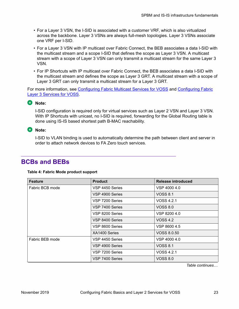
BCBs and BEBsTable 4: Fabric Mode product support
Feature Product Release introducedFabric BCB mode VSP 4450 Series VSP 4000 4.0
VSP 4900 Series VOSS 8.1VSP 7200 Series VOSS 4.2.1VSP 7400 Series VOSS 8.0VSP 8200 Series VSP 8200 4.0VSP 8400 Series VOSS 4.2VSP 8600 Series VSP 8600 4.5XA1400 Series VOSS 8.0.50
Fabric BEB mode VSP 4450 Series VSP 4000 4.0VSP 4900 Series VOSS 8.1VSP 7200 Series VOSS 4.2.1VSP 7400 Series VOSS 8.0
Table continues…
SPBM and IS-IS infrastructure fundamentals
November 2019 Configuring Fabric Basics and Layer 2 Services for VOSS 23

Feature Product Release introducedVSP 8200 Series VSP 8200 4.0VSP 8400 Series VOSS 4.2VSP 8600 Series VSP 8600 6.1XA1400 Series VOSS 8.0.50
The boundary between the core MAC-in-MAC SPBM domain and the edge customer 802.1Qdomain is handled by Backbone Edge Bridges (BEBs). I-SIDs are provisioned on the BEBs to beassociated with a particular service instance.
In the SPBM core, the bridges are referred to as Backbone Core Bridges (BCBs). BCBs forwardencapsulated traffic based on the BMAC-DA.
Important:
SPBM separates the payload from the transport over the SPBM infrastructure. Configure allvirtualization services on the BEBs at the edge of the network. There is no provisioning requiredon the core SPBM switches. This provides a robust carrier grade architecture whereconfiguration on the core switches never needs to be touched when adding new services.
A BEB performs the same functionality as a BCB, but it also terminates one or more Virtual ServiceNetworks (VSN). A BCB does not terminate any VSNs and is unaware of the VSN traffic ittransports. A BCB simply knows how to reach any other BEB in the SPBM backbone.
VLANs without member portsIf a VLAN is attached to an I-SID there must be another instance of that same I-SID in the SPBMnetwork.
• If another instance of that I-SID exists, the device designates that VLAN as operationally upregardless of whether it has a member port or not.
When the VLAN is operationally up, the IP address of the VLAN will be in the routing table.
• If no matching instance of the I-SID exists in the SPBM network, then that VLAN has noreachable members and does not act as an NNI interface.
The VLAN does not act as a UNI interface because it does not have a member port.
Therefore, the device does not designate the VLAN as operationally up because the VLANdoes not act as a UNI or an NNI interface.
If the device acts as a BCB with two VLANs configured and two I-SIDs, there must be a UNI sidewith the corresponding I-SID existing in the network.
If the device acts as both BEB and BCB, then there must be a member port in that VLAN to pushout the UNI traffic.
SPBM and IS-IS infrastructure configuration
November 2019 Configuring Fabric Basics and Layer 2 Services for VOSS 24

Basic SPBM network topologyThe following figure shows a basic SPBM network topology, specifically a Layer 2 VSN. Switches Aand D are the Backbone Edge Bridges (BEB) that provide the boundary between the customerVLANs (C-VLAN) and the Backbone. Switches B and C are the Backbone Core Bridges (BCB) thatform the core of the SPBM network.
Figure 3: SPBM L2 VSN
SPBM uses IS-IS in the core so that all BEBs and BCBs learn the IS-IS System-ID (B-MAC) ofevery other switch in the network. For example, BEB-A uses IS-IS to build an SPBM unicastforwarding table containing the B-MAC of switches BCB-B, BCB-C, and BEB-D.The BEBs provide the boundary between the SPBM domain and the virtualized services domain.For a Layer 2 VSN service, the BEBs map a C-VLAN to an I-SID based on local serviceprovisioning. Any BEB in the network that has the same I-SID configured can participate in the sameLayer 2 VSN.In this example, BEB A and BEB D are provisioned to associate C-VLAN 20 with I-SID 100. WhenBEB A receives traffic from C-VLAN 20 that must be forwarded to the far-end location, it performs alookup and determines that C-VLAN 20 is associated with I-SID 100 and that BEB D is thedestination for I-SID 100. BEB A then encapsulates the data and C-MAC header into a new B-MACheader, using its own nodal B-MAC: A as the source address and B-MAC: D as the destinationaddress. BEB A then forwards the encapsulated traffic to BCB B.To forward traffic in the core toward the destination node D, BCB B and BCB C perform Ethernetswitching using the B-MAC information only.
SPBM and IS-IS infrastructure fundamentals
November 2019 Configuring Fabric Basics and Layer 2 Services for VOSS 25

At BEB D, the node strips off the B-MAC encapsulation, and performs a lookup to determine thedestination for traffic with I-SID 100. BEB D identifies the destination on the C-VLAN header as C-VLAN 20 and forwards the packet to the appropriate destination VLAN and port.
E-Tree and Private VLAN topologyTable 5: E-Tree and Private VLANs product support
Feature Product Release introducedE-Tree and Private VLANs VSP 4450 Series VSP 4000 4.0
VSP 4900 Series VOSS 8.1VSP 7200 Series VOSS 4.2.1VSP 7400 Series VOSS 8.0VSP 8200 Series VOSS 4.1VSP 8400 Series VOSS 4.2VSP 8600 Series Not SupportedXA1400 Series Not Supported
Ethernet Private Tree (E-Tree) extends Shortest Path Bridging MAC (SPBM) to Private VLANs(PVLAN).Transport within the SPBM network is achieved by associating the private VLAN with an I-SID.Flooded traffic from both promiscuous and isolated devices is transported over the same I-SIDmulticast tree and suppression for spoke-to-spoke traffic is done on the egress SPB Backbone EdgeBridge (BEB). This means the Private VLAN IDs are globally significant and must be the same on allBEBsThe following list provides details for E-Tree and Private VLAN topology:
• E-Tree associates a Private VLAN with an I-SID.
Note:The same I-SID could be attached to a regular VLAN. In that case, all ports on the regularVLAN behave like Promiscuous ports on the PVLAN.
• Other SPB BEBs can associate a regular CVLAN to the same I-SID that E-Tree uses.
Note:The CVLAN ID must match the primary PVLAN ID.
• CVLAN devices assigned to the same I-SID that E-Tree uses have Promiscuous connectivitywithin the segment.
The following figure shows a basic E-Tree network topology consisting of groups of private VLANsconnected by the SPBM core network.
SPBM and IS-IS infrastructure configuration
November 2019 Configuring Fabric Basics and Layer 2 Services for VOSS 26

Figure 4: Sample E-Tree configuration
Private VLAN port typesThe private VLAN port type is isolated, promiscuous, or trunk. If the port is a member of an MLT,then the port inherits the private VLAN type of the MLT.In terms of network topology, the isolated port is considered a spoke. The isolated port, or spoke,does not communicate with any other isolated port in the network. The isolated port onlycommunicates with the promiscuous ports, or hubs.
E-Tree and Private VLAN limitationsThe following limitations apply to E-Tree and Private VLAN topology:
• A port that is of Private VLAN type trunk must be tagged. Isolated and Promiscuous PrivateVLAN ports can be either tagged or untagged.
• When a port or MLT that has a Private VLAN type set to Isolated or Promiscuous is added to aprivate VLAN, if that port is used by other non private VLANs, then those non private VLANsare removed.
• A port which is Private VLAN type Isolated and is tagged can belong to only one Private VLAN.
IS-ISTable 6: IS-IS product support
Feature Product Release introducedIS-IS authentication with SHA-256 VSP 4450 Series VOSS 7.0
Table continues…
SPBM and IS-IS infrastructure fundamentals
November 2019 Configuring Fabric Basics and Layer 2 Services for VOSS 27
Feature Product Release introducedVSP 4900 Series VOSS 8.1VSP 7200 Series VOSS 7.0VSP 7400 Series VOSS 8.0VSP 8200 Series VOSS 7.0VSP 8400 Series VOSS 7.0VSP 8600 Series VSP 8600 6.1XA1400 Series Not Supported
Suspend duplicate system IDdetection
VSP 4450 Series VOSS 6.1VSP 4900 Series VOSS 8.1VSP 7200 Series VOSS 6.1VSP 7400 Series VOSS 8.0VSP 8200 Series VOSS 6.1VSP 8400 Series VOSS 6.1VSP 8600 Series VSP 8600 6.1XA1400 Series VOSS 8.0.50
Multiple IS-IS parallel adjacencies VSP 4450 Series VOSS 7.0VSP 4900 Series VOSS 8.1VSP 7200 Series VOSS 7.0VSP 7400 Series VOSS 8.0VSP 8200 Series VOSS 7.0VSP 8400 Series VOSS 7.0VSP 8600 Series Not SupportedXA1400 Series Not Supported
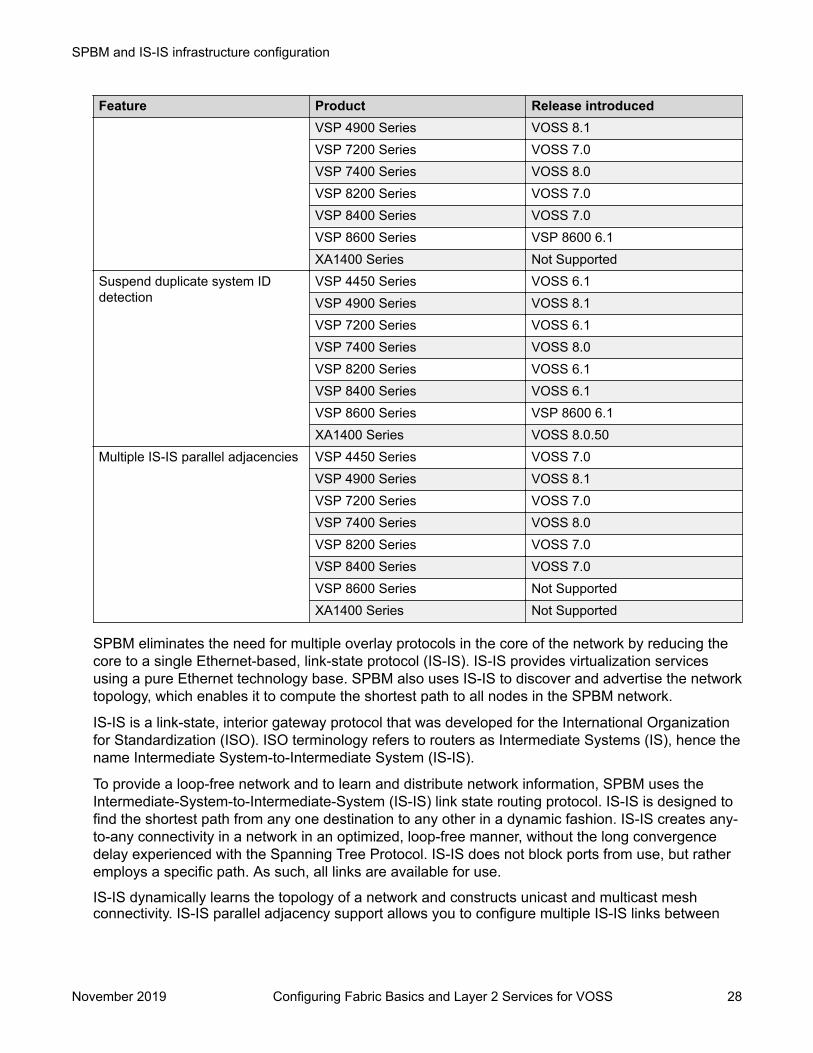
SPBM eliminates the need for multiple overlay protocols in the core of the network by reducing thecore to a single Ethernet-based, link-state protocol (IS-IS). IS-IS provides virtualization servicesusing a pure Ethernet technology base. SPBM also uses IS-IS to discover and advertise the networktopology, which enables it to compute the shortest path to all nodes in the SPBM network.
IS-IS is a link-state, interior gateway protocol that was developed for the International Organizationfor Standardization (ISO). ISO terminology refers to routers as Intermediate Systems (IS), hence thename Intermediate System-to-Intermediate System (IS-IS).
To provide a loop-free network and to learn and distribute network information, SPBM uses theIntermediate-System-to-Intermediate-System (IS-IS) link state routing protocol. IS-IS is designed tofind the shortest path from any one destination to any other in a dynamic fashion. IS-IS creates any-to-any connectivity in a network in an optimized, loop-free manner, without the long convergencedelay experienced with the Spanning Tree Protocol. IS-IS does not block ports from use, but ratheremploys a specific path. As such, all links are available for use.
IS-IS dynamically learns the topology of a network and constructs unicast and multicast meshconnectivity. IS-IS parallel adjacency support allows you to configure multiple IS-IS links between
SPBM and IS-IS infrastructure configuration
November 2019 Configuring Fabric Basics and Layer 2 Services for VOSS 28

the two nodes. Each node in the network calculates a shortest-path tree to every other networknode based on System-IDs (B-MAC addresses). Only one adjacency with the shortest path isselected as an active adjacency.
Note:Only an active interface with an active adjacency is added into local SPF calculations. Thismechanism ensures the local node selects the shortest path and has the same view as the restof the SPB network.
In the SPBM environment for Layer 2 VSNs, IS-IS carries only pure Layer 2 information with norequirement for an underlying IP control plane or forwarding path. IS-IS runs directly over Layer 2.
Note:SPBM carries Layer 3 information for Layer 3 VSNs.
In SPBM networks, IS-IS performs the following functions:• Discovers the network topology• Builds shortest path trees between the network nodes:
- Forwards unicast traffic- Determines the forwarding table for multicast traffic
• Communicates network information in the control plane:- Service Instance Identifier (I-SID) information
SPBM can distribute I-SID service information to all SPBM nodes, as the I-SIDs are created. SPBMincludes I-SID information in the IS-IS Link State protocol data units (PDUs). When a new serviceinstance is provisioned on a node, its membership is flooded throughout the topology using an IS-ISadvertisement.
Standard TLVsIS-IS uses Type-Length-Value (TLV) encoding. SPBM employs IS-IS as the interior gatewayprotocol and implements additional TLVs to support additional functionality. The switch also supportsSub-TLVs. TLVs exist inside IS-IS packets and Sub-TLVs exist as additional information in TLVs.The switch supports and is in full compliance with standard 802.1 aq TLVs. The IEEE ratified the802.1aq standard that defines SPBM and the Type-Length-Value (TLV) encoding that IS-IS uses tosupport SPBM services. The following table lists all the TLVs that the switch supports.
Table 7: Standard TLVs
TLV Description Usage1 Area addresses — The Area
Addresses TLV contains the areaaddresses to which the IS-IS isconnected.
IS-IS area
Table continues…
SPBM and IS-IS infrastructure fundamentals
November 2019 Configuring Fabric Basics and Layer 2 Services for VOSS 29

TLV Description Usage22 Extended IS reachability — The
Extended IS Reachability TLVcontains information aboutadjacent neighbors.
IS-IS adjacencies
Sub-TLV 29: SPBM link metric iscarried within this TLV.
129 Protocols supported — TheProtocol supported TLV carries theNetwork Layer Protocol Identifiers(NLPID) for the Network Layerprotocols where the IS-IS can beused.
SPBM in addition to existingNLPID (IPV4 0xCC, IPV6 0x*E..),IEEE 802.1aq defined SPBMNLPID as 0xC1.
135 Extended IP reachability — TheExtended IP Reachability TLV 135is used to distribution IPreachability between IS-IS peers.
SPBM uses this existing IS-IS TLVto carry IP Shortcut routes in theGlobal Routing Table (GRT).
143 Multi-topology port awarecapability (MT-Port-Capability)TLV
This TLV carries the SPB instanceID in a multiple SPB instancesenvironment. This TLV is carriedwithin IS-IS Hello Packets (IIH),only when parallel links exist.
This TLV carries the followingSPBM Sub TLV:
• Sub-TLV 6: SPB B-VID Sub TLVindicates the mapping betweena VLAN and its equal cost tree(ECT) algorithm. To form anadjacency, both nodes musthave a matching primary(BVLAN, ECT) pair, andsecondary (BVLAN, ECT) pair,the number of B-VLANs must beequal, B-VLAN values mustmatch, ECT values for the B-VLANs must match. Used in IS-IS Hellos only.
• MCID Sub TLV: The MCID is adigest of the VLANs and MSTI.Neighboring SPBM nodes mustagree on the MCID to form anadjacency. The MCID is set to allzeros (0).
After the switch receives a non-zero MCID Sub TLV, it reflectscontent back to the neighbor.
• Link L1 Metric Sub-TLV 7:Contains L1 metric of the link
144 Multi-topology Capability (MT-Capability) TLV.
This TLV carries the SPB instanceID in a multiple SPB instance
TLV 144 is the service identifierTLV. TLV 144 advertizes B-MACand I-SID information.
Table continues…
SPBM and IS-IS infrastructure configuration
November 2019 Configuring Fabric Basics and Layer 2 Services for VOSS 30

TLV Description Usageenvironment. This TLV is carriedwithin LSPs.
In multicast over Fabric Connect,TLV 144 on the BEB bridge, wherethe sender is located, has thetransmit (Tx) bit set. On the BEBbridge, where the receiver islocated the receive (Rx) bit is set.
This TLV carries the following SubTLVs:
Sub-TLV 1: SPB instance Sub TLVcontains a unique SPSourceID(nickname) to identify the SPBMnode within this SPB topology.
Sub-TLV 3: SPB Service ID (I-SID)is stored in TLV 144 sub-TLV 3.Sub-TLV 3 carries service groupmembership (I-SIDs) for aparticular SPBM B-VLAN.
184 SPBM IP VPN reachability — IS-IS TLV 184 is used to advertiseSPBM L3 VSN route informationacross the SPBM cloud.
IP reachability for Layer 3 VSNs
185 IPVPN multicast TLV with IPMCsub TLV — The IPVPN multicastTLV contains information aboutthe scope I-SID.
TLV 185 on the BEB bridge, wherethe source is located, displays themulticast source and groupaddresses and has the transmit(Tx) bit set. Each multicast grouphas its own data I-SID that mapsto the source and groupaddresses.
As part of the IPVPN TLV, sub-TLVs define IPv4 unicast, IPv6unicast and IPv4 multicastinformation.
Layer 2 VSN IP multicast overFabric Connect and Layer 3 VSNIP multicast over Fabric Connect(using VRF) use TLV 185.
186 IP multicast TLV (GRT) — TLV186 on the BEB bridge, where thesource is located, displays themulticast source and groupaddresses and has the transmit(Tx) bit set. Each multicast grouphas its own data I-SID that mapsto the source and groupaddresses.
IP Shortcuts with IP multicast overFabric Connect use TLV 186.
All multicast streams areconstrained within the level inwhich they originate, which iscalled the scope level.
236 IPv6 Reachability — The IPv6reachability TLV 236 is used todistribute IPv6 networkreachability between IS-IS peers.
SPBM uses the existing IS-IS TLVto carry IPv6 shortcut routesthrough the SPBM core.
SPBM and IS-IS infrastructure fundamentals
November 2019 Configuring Fabric Basics and Layer 2 Services for VOSS 31

For more information on IP multicast over Fabric Connect, see Configuring Fabric Multicast Servicesfor VOSS.
IS-IS hierarchiesIS-IS is a dynamic routing protocol that operates within an autonomous system (or domain). IS-ISprovides support for hierarchical routing, which enables you to partition large routing domains intosmaller areas. When used separately from SPBM, IS-IS uses a two-level hierarchy, dividing thedomain into multiple Level 1 areas and one Level 2 area. When used separately from SPBM, theLevel 2 area serves as backbone of the domain, connecting to all the Level 1 areas. SPBM currentlyuses only Level 1 areas.
Important:The IEEE 802.1aq standard currently only defines the use of one hierarchy, Level 1. Level 2function is disabled.
IS-IS PDUsIntermediate System to Intermediate System Hello (IIH) packets discover IS-IS neighbors andestablish and maintain IS-IS adjacencies. An IIH is sent in every Hello-interval to maintain theestablished adjacency. If a node has not heard IIHs from its neighbor for (hello-interval x hello-multiple) seconds, the node tears down the adjacency. IIH carries TLV 143 and SPB-B-VLAN Sub-TLV (among other sub-TLVs). For two nodes to form an adjacency the B-VLAN pairs for primary B-VLAN and secondary B-VLAN must match.Link State Packets (LSP) advertise link state information. The system uses the link state informationto compute the shortest path. LSP also advertises MT-capability TLV 144 and SPB instance Sub-TLV, and SPB I-SIDs Sub-TLV.Complete Sequence Number Packets (CSNP) contain the most recent sequence numbers of allLSPs in the database. CSNP notifies neighbors about the local LSDB. After a neighbor receives aCSNP, it compares the LSPs in the CSNP with the LSP in the local LSDB. If the neighbor is missingLSPs, it sends a Partial Sequence Number Packets (PSNP) to request the missing LSPs. Thisprocess synchronizes the LSDBs among neighbors. A synchronized LSDB among all nodes in thenetwork is crucial to producing a loop-free shortest path.
IS-IS configuration parametersIS-IS system identifiersThe IS-IS system identifiers consist of three parts:
• System ID — The system ID is any 6 bytes that are unique in a given area or level. The systemID defaults to the baseMacAddress of the chassis but you can configure a non-default value.The system ID must use a unicast MAC address; do not use a multicast MAC address. A MACaddress that has the low order bit 1 set in the highest byte is a multicast MAC address. Forexample, the following are multicast MAC addresses: x1xx.xxxx.xxxx, x3xx.xxxx.xxxx,
SPBM and IS-IS infrastructure configuration
November 2019 Configuring Fabric Basics and Layer 2 Services for VOSS 32

x5xx.xxxx.xxxx, x7xx.xxxx.xxxx, x9xx.xxxx.xxxx, xBxx.xxxx.xxxx, xDxx.xxxx.xxxx, andxFxx.xxxx.xxxx.
• Manual area — The manual area or area ID is up to 13 bytes long. The first byte of the areanumber (for example, 49) is the Authority and Format Indicator (AFI). The next bytes are theassigned domain (area) identifier, which is up to 12 bytes (for example,49.0102.0304.0506.0708.0910.1112). IS-IS supports a maximum of three manual areas, butthe switch software only supports one manual area.
• NSEL — The last byte (00) is the n-selector. In this implementation, this part is automaticallyattached. There is no user input accepted.
The Network Entity Title (NET) is the combination of all three global parameters.All routers have at least one manual area. Typically, a Level 1 router does not participate in morethan one area.The following are the requirements for system IDs:
• All IS-IS enabled routers must have one manual area and a unique system ID.• All routers in the same area must have the same area ID.• All routers must have system IDs of the same length (6 bytes).• All IS-IS enabled routers must have a unique nickname.
PSNP intervalYou can change the PSNP interval rate. A longer interval reduces overhead, while a shorter intervalspeeds up convergence.
CSNP periodic and interval rateYou can configure the CSNP periodic and interval rate. A longer interval reduces overhead, while ashorter interval speeds up convergence.
Parameters for the link state packet (LSP)LSPs contain vital information about the state of adjacencies, which must be exchanged withneighboring IS-IS systems. Routers periodically flood LSPs throughout an area to maintainsynchronization. You can configure the LSP to reduce overhead or speed up convergence.The following list describes IS-IS parameters related to LSPs:
• The max-lsp-gen-interval is the time interval at which the generated LSP is refreshed.The default is 900 seconds with a range of 30 to 900.
• The retransmit-lsp-interval is the minimum amount of time between retransmission ofan LSP. When transmitting or flooding an LSP an acknowledgement (ACK) is expected. If theack is not received within retransmit-lsp-interval, the LSP is re-transmitted. Thedefault is 5 seconds with a range of 1 to 300.
Point-to-point modeAll SPBM links are point-to-point links. The switch does not support broadcast links.
IS-IS interface authenticationConfigure IS-IS interface authentication to improve security and to guarantee that only trustedrouters are included in the IS-IS network. Interface level authentication only checks the IIH PDUs. If
SPBM and IS-IS infrastructure fundamentals
November 2019 Configuring Fabric Basics and Layer 2 Services for VOSS 33

the authentication type or key in a received IIH does not match the locally-configured type and key,the IIH is rejected. By default, authentication is disabled.You can use either one of the following authentication methods:
• Simple password authentication — Uses a text password in the transmitted packet. Thereceiving router uses an authentication key (password) to verify the packet.
• MD5 authentication — Creates a Message Digest (MD5) key.• SHA-256 — Adds a Hash-based Message Authentication Code (HMAC) digest to each IS-IS
Hello packet.
Important:If the .isis_md5key.txt and .isis_simplekey.txt are missing, IS-IS adjacencies cannot beestablished.
Password considerationsTo reset the authentication password type, you must set the type to none.The switch software supports only interface level authentication. The switch software does notsupport area level or domain level authentication.
SHA-256 considerationsIS-IS Hello packets are sent periodically to discover IS-IS neighbors, and to establish and maintainIS-IS adjacencies. If you enable SHA-256 authentication, the switch adds an HMAC-SHA256 digestto each Hello packet.
Note:The interfaces used to make the adjacencies must have SPBM configured.
The switch that receives the Hello packet computes the digest of the packet and compares it withthe received digest. If the digests match, the packet is accepted. If the digests do not match, thereceiving switch discards the packet.Directly connected switches must share the same key (secret), which can have a maximum lengthof 16 characters.
HellosTo update the identities of neighboring routers, you can configure the:
• Interface Hello interval• Interface Hello multiplier
Interface Hello intervalIS-IS uses Hello packets to initialize and maintain adjacencies between neighboring routers.You can configure the interface level Hello interval to change how often Hello packets are sent outfrom an interface level.
Hello multiplierYou can configure the Hello multiplier to specify how many Hellos the switch must miss before itconsiders the adjacency with a neighboring switch down. By default, the hold (wait) time is the Hellointerval multiplied by the Hello multiplier. By default, if the Hello interval is 9 and the Hello multiplieris 3, the hold time is 27. If the Hello multiplier is increased to 10, the hold time is increased to 90.
SPBM and IS-IS infrastructure configuration
November 2019 Configuring Fabric Basics and Layer 2 Services for VOSS 34

Link metricYou can configure the link metric to overwrite the default metric value. By configuring the metric, youcan specify a preferred path. Low cost reflects high-speed media, and high cost reflects slowermedia. For the wide metric, the value ranges from 1 to 16,777,215.
• The switch only supports the wide metric.• The total cost of a path equals the sum of the cost of each link.• The default value for wide metrics is 10.
Note:When multiple paths exist to reach a node, the path with the lowest sum of metrics of theindividual links is chosen. If the sum of the paths are the same, the one with the lowest numberof hops is chosen. If the number of hops is the same as well, then the tie-breaking is done bythe system ID.For the primary BVLAN, the path that has a node with the lowest system ID is chosen.Whereas, for the secondary BVLAN, the path that has a node with the highest system ID ischosen.
Disabling IS-ISYou can disable IS-IS globally or at the interface level. If IS-IS is globally disabled, then all IS-ISfunctions stop. If IS-IS is enabled at the global level and disabled at one of the interface levels, thenIS-IS continues on all other interfaces.
Overload bitThe overload bit is sent by a node in LSP updates to inform other devices, whether to use that nodeto pass transit traffic. For example, when an LSP with an overload bit is received, the device ignoresthat LSP in its SPF calculation to avoid sending transit traffic through the overloaded node; howeverthe overloaded node can still receive traffic destined to itself.The overload bit is turned on by default on bootup, and cleared after 20 seconds. You can use theoverload-on-startup parameter to control the time before the overload bit is cleared afterbootup, as this setting is user configurable.You can permanently set the overload bit using the overload parameter. If this is configured, theoverload bit will not be cleared after bootup and it will be sent in all LSP updates. If the overload bitis set permanently, other devices do not include this node for use as a transit node in IS-IScomputations. By default, the overload parameter is set to false.
The overload and overload-on-startup parameters are two independent settings and areconfigured under the router isis configuration mode in the CLI.
SPBM B-VLANEach SPBM network instance is associated with at least one backbone VLAN (B-VLAN) in the coreSPBM network.
SPBM and IS-IS infrastructure fundamentals
November 2019 Configuring Fabric Basics and Layer 2 Services for VOSS 35
Note:
SPB internally uses spanning tree group (STG) 63 or Multiple Spanning Tree Instance (MSTI)62. STG 63 or MSTI 62 cannot be used by another VLAN or MSTI. For non-SPB customernetworks, if you use STG 63 or MSTI 62 in the configuration, you must delete STG 63 or MSTI62 before you can configure SPBM.
This VLAN is used for both control plane traffic and dataplane traffic.
Note:Always configure two B-VLANs in the core to allow load distribution over both B-VLANs.
SPBM alters the behavior of the VLAN. When a B-VLAN is associated with an SPBM network thefollowing VLAN attributes and behaviors are modified for the B-VLAN:
• Flooding is disabled• Broadcasting is disabled• Source address learning is disabled• Unknown MAC discard is disabled
You cannot add ports to a B-VLAN manually, IS-IS enabled ports are automatically added to the B-VLAN.Essentially the B-MAC addresses are programmed into the B-VLAN Forwarding Information Bases(FIBs) by IS-IS instead of the traditional VLANs flooding and learning approach.Modification of the VLAN behavior is necessary to ensure proper control over the SPBM traffic.
Pre-populated FIBAn Ethernet network usually learns MAC addresses as frames are sent through the switch. Thisprocess is called reverse learning and is accomplished through broadcast.
SPBM does not allow any broadcast flooding of traffic on the B-VLAN in order to prevent loopingaccomplished through flooding packets with unknown destinations (although multicast traffic issupported). As such, MAC addresses must be distributed within SPBM. This is accomplished bycarrying the necessary B-MAC addresses inside the IS-IS link state database. To that end, SPBMsupports an IS-IS TLV that advertises the I-SID and B-MAC information across the network. Thisfunctionality enables the powerful end-point-provisioning of SPBM.
These Backbone MAC addresses are populated into the SPBM VLAN Forwarding Information Base(FIB) to maximize efficiency and to allow Reverse Path Forwarding Check (RPFC) to operateproperly.
RPFCA loop prevention mechanism is required at Layer 2 to stop wayward traffic from crippling thenetwork. Reverse Path Forwarding Check (RPFC) is the chosen method of suppressing loop trafficwith SPBM. RPFC was originally designed for IP traffic at Layer 3 where it checks the source
SPBM and IS-IS infrastructure configuration
November 2019 Configuring Fabric Basics and Layer 2 Services for VOSS 36

address of the packet against the routing entry in the routing table. The source address must matchthe route for the port it came in on otherwise the packet is illegitimate and therefore dropped.
With SPBM, the node matches the source B-MAC address against the ingress port to establishvalidity. If the frame is not supposed to come in that port, it is immediately suppressed imposing aguaranteed loop control. If there is no VLAN FDB entry to the source MAC address with theoutgoing port as the ingress port, the frame will be dropped.
SPBM FIBThis section describes the SPBM unicast and multicast FIBs.
Unicast FIBThe unicast computation runs a single Dijkstra (unlike all pair Dijkstras for multicast). SPBMproduces only one Shortest Path First (SPF) tree and the tree is rooted on the computing node.The unicast computation generates an entry for each node in the network. The Destination Address(DA) for that entry is the system-id of the node. In addition, if a node advertises MAC addressesother than the system-id, each MAC address has an entry in the unicast FIB table, and the shortestpath to that MAC should be exactly the same as the path to the node.Unicast FIB entries are installed to the vlan-fdb table.The following text shows an example of the unicast FIB.Switch:1# show isis spbm unicast-fib================================================================================ SPBM UNICAST FIB ENTRY INFO================================================================================DESTINATION BVLAN SYSID HOST-NAME OUTGOING COSTADDRESS INTERFACE--------------------------------------------------------------------------------00:80:2d:35:93:df 10 0080.2d35.93df 86-10 MLT-32 000:80:2d:35:93:df 11 0080.2d35.93df 86-10 MLT-32 000:80:86:10:86:20 11 0080.2d35.93df 86-10 MLT-32 000:e0:7b:84:57:df 10 00e0.7b84.57df 86-30 1/12 000:e0:7b:84:57:df 11 00e0.7b84.57df 86-30 1/12 0
Multicast FIBSPBM runs all pair Dijkstras to produce the multicast FIB. The computing node loops through eachnode to run Dijkstra using that node as the root, and then prunes paths to only keep the shortestpaths. The computing node then computes the intersection of the set of I-SIDs for which the rootnode transmits, with the set of I-SIDs for which the path endpoints receive.The multicast addresses are built out of two pieces: the SPBM Node Nickname and the I-SID IDconverted to hexadecimal format to form the multicast MAC address.|----------------------------|---------------------------------| nickname|0x30000 hexadecimal I-SID
For example, if the nickname is 0.00.10 and the I-SID is 100 (0x64), the multicast address is03:00:10:00:00:64.
SPBM and IS-IS infrastructure fundamentals
November 2019 Configuring Fabric Basics and Layer 2 Services for VOSS 37
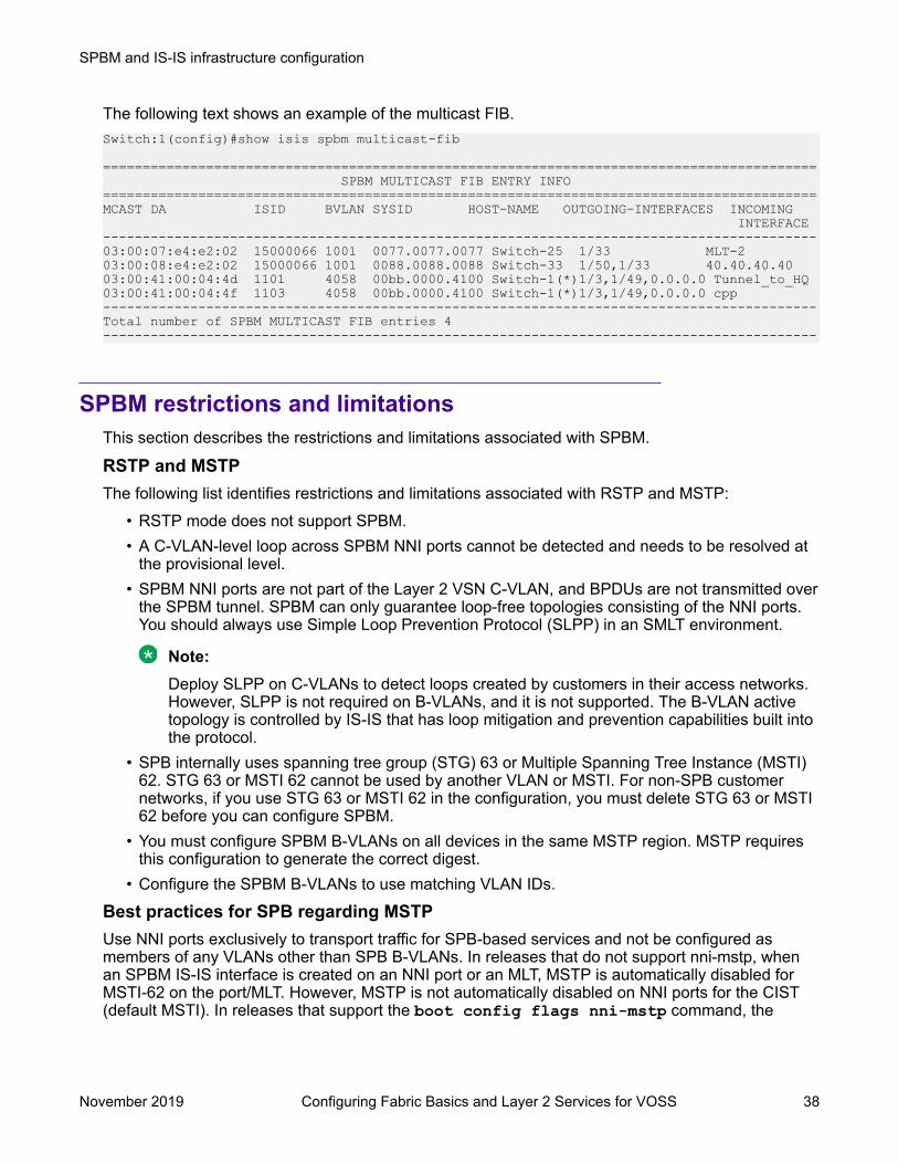
The following text shows an example of the multicast FIB.Switch:1(config)#show isis spbm multicast-fib
========================================================================================== SPBM MULTICAST FIB ENTRY INFO==========================================================================================MCAST DA ISID BVLAN SYSID HOST-NAME OUTGOING-INTERFACES INCOMING INTERFACE------------------------------------------------------------------------------------------03:00:07:e4:e2:02 15000066 1001 0077.0077.0077 Switch-25 1/33 MLT-203:00:08:e4:e2:02 15000066 1001 0088.0088.0088 Switch-33 1/50,1/33 40.40.40.4003:00:41:00:04:4d 1101 4058 00bb.0000.4100 Switch-1(*)1/3,1/49,0.0.0.0 Tunnel_to_HQ03:00:41:00:04:4f 1103 4058 00bb.0000.4100 Switch-1(*)1/3,1/49,0.0.0.0 cpp------------------------------------------------------------------------------------------Total number of SPBM MULTICAST FIB entries 4------------------------------------------------------------------------------------------
SPBM restrictions and limitationsThis section describes the restrictions and limitations associated with SPBM.
RSTP and MSTPThe following list identifies restrictions and limitations associated with RSTP and MSTP:
• RSTP mode does not support SPBM.• A C-VLAN-level loop across SPBM NNI ports cannot be detected and needs to be resolved at
the provisional level.• SPBM NNI ports are not part of the Layer 2 VSN C-VLAN, and BPDUs are not transmitted over
the SPBM tunnel. SPBM can only guarantee loop-free topologies consisting of the NNI ports.You should always use Simple Loop Prevention Protocol (SLPP) in an SMLT environment.
Note:Deploy SLPP on C-VLANs to detect loops created by customers in their access networks.However, SLPP is not required on B-VLANs, and it is not supported. The B-VLAN activetopology is controlled by IS-IS that has loop mitigation and prevention capabilities built intothe protocol.
• SPB internally uses spanning tree group (STG) 63 or Multiple Spanning Tree Instance (MSTI)62. STG 63 or MSTI 62 cannot be used by another VLAN or MSTI. For non-SPB customernetworks, if you use STG 63 or MSTI 62 in the configuration, you must delete STG 63 or MSTI62 before you can configure SPBM.
• You must configure SPBM B-VLANs on all devices in the same MSTP region. MSTP requiresthis configuration to generate the correct digest.
• Configure the SPBM B-VLANs to use matching VLAN IDs.
Best practices for SPB regarding MSTPUse NNI ports exclusively to transport traffic for SPB-based services and not be configured asmembers of any VLANs other than SPB B-VLANs. In releases that do not support nni-mstp, whenan SPBM IS-IS interface is created on an NNI port or an MLT, MSTP is automatically disabled forMSTI-62 on the port/MLT. However, MSTP is not automatically disabled on NNI ports for the CIST(default MSTI). In releases that support the boot config flags nni-mstp command, the
SPBM and IS-IS infrastructure configuration
November 2019 Configuring Fabric Basics and Layer 2 Services for VOSS 38

default behavior of the MSTP NNI ports is that CIST is disabled automatically on the NNI and theNNI ports cannot be members of any VLANs other than B-VLANs. The default boot config flags nni-mstp must be set to false (which is the default). The following example shows the command todisable the MSTP on the NNI ports.Switch:1(config)#interface gigabitEthernet 1/8Switch:1(config-if)#no spanning-tree mstp
Coexistence of MSTP and SPB based services on NNI ports:In releases that do not support nni-mstp boot configuration, you can support the coexistence of non-SPB based services on the NNI ports, by adding NNI ports as members of VLANs, except for B-VLANs. These other VLANs rely on the use of MSTP for Loop prevention. The network operatormust carefully consider the implications of keeping MSTP enabled on the NNI ports because anyMSTP topology changes detected on the NNI ports impacts all services and causes mostdynamically learned information on the UNI side to be flushed and relearned. This includes, but isnot limited to, all customer MAC and ARP records. This can also cause all the UNI ports on a BEBto be temporarily put into a spanning-tree blocking state before transitioning to a forwarding stateagain. The net result is that MSTP topology changes on the NNI ports adversely impact traffic forSPB-based services. Therefore, it is recommended that the NNI ports be used exclusively for SPBtraffic.
SPBM IS-ISThe following list identifies restrictions and limitations associated with SPBM IS-IS:
• The switch does not support IP over IS-IS as defined by RFC 1195. IS-IS protocol is only tofacilitate SPBM.
• The switch uses level 1 IS-IS. The switch does not support level 2 IS-IS. The CLI commandshow isis int-l2-contl-pkts is not supported because the IEEE 802.1aq standardcurrently only defines the use of one hierarchy, Level 1.
• The IS-IS standard defines wide (32bit ) metrics and narrow (8 bits) metrics. The switchsupports the wide metric.
• IS-IS enabled ports cannot be added to an MLT. The switch does not support this configuration.
SPBM NNI SMLTThe switch does not support NNI on SMLT links.
VLACPVLACP is generally used when a repeater or switch exists between connected switches to detectwhen a connection is down even when the link LED is lit. If you configure VLACP on an SPBM linkthat is also an IST link, during a connection fail over (where the link LED stays lit) the IS-IS hellostime out first (after 27 seconds, using default values) and take down the IS-IS adjacency. IS-IS thencalculates the new shortest path and fails over the SPBM traffic. 90 seconds after the connectionfailure (using default values), VLACP goes down but the IST link was already taken down by IS-IS.In this scenario, there is no data traffic impact because IS-IS can find another path in the SPBMnetwork before VLACP goes down.
SNMP trapsOn each SPBM peer, if you configure the SPBM B-VLANs to use different VLAN IDs, for example,VLAN 10 and 20 on one switch, and VLAN 30 and 40 on the second, the system does not generatea trap message to alert of the mismatch because the two switches cannot receive control packetsfrom one another. Configure the SPBM B-VLANs to use matching VLAN IDs.
SPBM and IS-IS infrastructure fundamentals
November 2019 Configuring Fabric Basics and Layer 2 Services for VOSS 39

System MTUDo not change the system MTU to less than the default value of 1950 bytes. The system MTU mustbe 1950 or jumbo because of the header size increase when transmitting packets over the SPBMcloud.
IP multicast over Fabric ConnectIP multicast over Fabric Connect cannot connect to existing Protocol Independent Multicast (PIM)networks that connect to SPB originated streams or that add PIM network streams into the SPBnetwork. SPB-PIM Gateway (SPB-PIM GW), however, provides multicast interdomaincommunication between an SPB network and a PIM network. SPB-PIM GW accomplishes thisinterdomain communication across a special Gateway VLAN. The Gateway VLAN communicateswith the PIM network through the PIM protocol messaging and translates the PIM networkrequirements into SPB language, and vice versa. For more information about SPB-PIM GW, see Configuring Fabric Multicast Services for VOSS.
OtherThe following list identifies other restrictions and limitations:
• You cannot use 3.33.33 as the SPB nickname because of a conflict with reserved IPv6Ethernet multicast address 33:33:xx:xx:xx:xx.
• The software does not support I-SID filters.• You cannot enable C-VLAN and B-VLAN on the same port.
Network Load Balancing (NLB)Table 8: Network Load Balancing product support
Feature Product Release introducedNetwork Load Balancing (NLB) -multicast operation
VSP 4450 Series Not SupportedVSP 4900 Series VOSS 8.1VSP 7200 Series VOSS 6.0VSP 7400 Series VOSS 8.0VSP 8200 Series VOSS 6.0VSP 8400 Series VOSS 6.0VSP 8600 Series Not SupportedXA1400 Series Not Supported
Network Load Balancing (NLB) -unicast operation
VSP 4450 Series Not SupportedVSP 4900 Series VOSS 8.1VSP 7200 Series VOSS 4.2.1VSP 7400 Series VOSS 8.0VSP 8200 Series VOSS 4.0
Table continues…
SPBM and IS-IS infrastructure configuration
November 2019 Configuring Fabric Basics and Layer 2 Services for VOSS 40
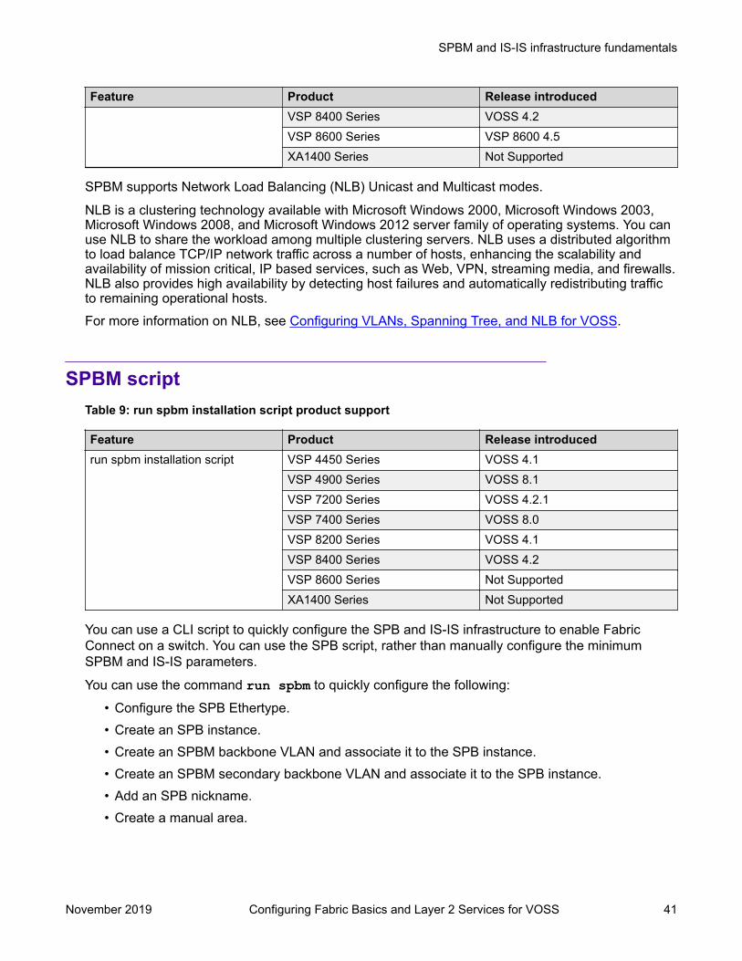
Feature Product Release introducedVSP 8400 Series VOSS 4.2VSP 8600 Series VSP 8600 4.5XA1400 Series Not Supported
SPBM supports Network Load Balancing (NLB) Unicast and Multicast modes.
NLB is a clustering technology available with Microsoft Windows 2000, Microsoft Windows 2003,Microsoft Windows 2008, and Microsoft Windows 2012 server family of operating systems. You canuse NLB to share the workload among multiple clustering servers. NLB uses a distributed algorithmto load balance TCP/IP network traffic across a number of hosts, enhancing the scalability andavailability of mission critical, IP based services, such as Web, VPN, streaming media, and firewalls.NLB also provides high availability by detecting host failures and automatically redistributing trafficto remaining operational hosts.For more information on NLB, see Configuring VLANs, Spanning Tree, and NLB for VOSS.
SPBM scriptTable 9: run spbm installation script product support
Feature Product Release introducedrun spbm installation script VSP 4450 Series VOSS 4.1
VSP 4900 Series VOSS 8.1VSP 7200 Series VOSS 4.2.1VSP 7400 Series VOSS 8.0VSP 8200 Series VOSS 4.1VSP 8400 Series VOSS 4.2VSP 8600 Series Not SupportedXA1400 Series Not Supported
You can use a CLI script to quickly configure the SPB and IS-IS infrastructure to enable FabricConnect on a switch. You can use the SPB script, rather than manually configure the minimumSPBM and IS-IS parameters.
You can use the command run spbm to quickly configure the following:
• Configure the SPB Ethertype.• Create an SPB instance.• Create an SPBM backbone VLAN and associate it to the SPB instance.• Create an SPBM secondary backbone VLAN and associate it to the SPB instance.• Add an SPB nickname.• Create a manual area.
SPBM and IS-IS infrastructure fundamentals
November 2019 Configuring Fabric Basics and Layer 2 Services for VOSS 41
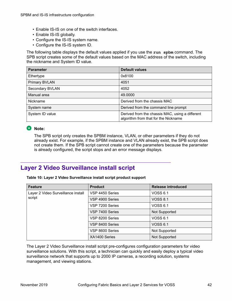
• Enable IS-IS on one of the switch interfaces.• Enable IS-IS globally.• Configure the IS-IS system name.• Configure the IS-IS system ID.
The following table displays the default values applied if you use the run spbm command. TheSPB script creates some of the default values based on the MAC address of the switch, includingthe nickname and System ID value.
Parameter Default valuesEthertype 0x8100Primary BVLAN 4051Secondary BVLAN 4052Manual area 49.0000Nickname Derived from the chassis MACSystem name Derived from the command line promptSystem ID value Derived from the chassis MAC, using a different
algorithm from that for the Nickname
Note:The SPB script only creates the SPBM instance, VLAN, or other parameters if they do notalready exist. For example, if the SPBM instance and VLAN already exist, the SPB script doesnot create them. If the SPB script cannot create one of the parameters because the parameteris already configured, the script stops and an error message displays.
Layer 2 Video Surveillance install scriptTable 10: Layer 2 Video Surveillance install script product support
Feature Product Release introducedLayer 2 Video Surveillance installscript
VSP 4450 Series VOSS 6.1VSP 4900 Series VOSS 8.1VSP 7200 Series VOSS 6.1VSP 7400 Series Not SupportedVSP 8200 Series VOSS 6.1VSP 8400 Series VOSS 6.1VSP 8600 Series Not SupportedXA1400 Series Not Supported
The Layer 2 Video Surveillance install script pre-configures configuration parameters for videosurveillance solutions. With this script, a technician can quickly and easily deploy a typical videosurveillance network that supports up to 2000 IP cameras, a recording solution, systemsmanagement, and viewing stations.
SPBM and IS-IS infrastructure configuration
November 2019 Configuring Fabric Basics and Layer 2 Services for VOSS 42

The install script uses best practices for converged solutions and provides redundant paths for allvideo traffic. The script configures the basic deployment of Shortest Path Bridging and uses Layer 2VSNs to enable full multicast capabilities between all IP subnets and VLANs.
Configuration parametersThe syntax of the install script command is run vms layer-2 switch <5-99> where the switchvalue (between 5 and 99) is a user-defined variable. The install script uses this switch value to setthe camera IP zone for the switch and to specify a unique SPB nickname, system-id, and IP sourcevalue.The install script configures the following major parameters and populates the xx with the user-defined variable for the switch value:
• IP Loopback Interface Address: 192.0.2.xx (Management IP address on the switch.)• IP-Source Address: 192.0.2.xx (IS-IS source IP address for the switch.)• VLAN ID: 200 (On hardware platforms that only have NNI links, there is no need to create a
surveillance VLAN.)• System ID: 0011.0011.07xx (SPB system-id of switch)• Nickname: 0.07.xx (SPB Nickname for switch)• SPB Manual Area ID: 49.0001• Backbone VLAN IDs: 4051 and 4052 (with 4051 as Primary)• SPB Mulitcast: enabled• SFP and SFP+ ports: (Define all ports as NNI links.)
Note:The install script does not configure DHCP Relay parameters.
Optional syntax parameterThe install script requires that the switch be in the factory default state. The script prompts you toconfirm this, but it does not check if you did so. The script continues executing commands even ifsome of the commands in the script fail, and the failure of script commands is not evident by thescript execution completion message.The complete syntax of the install script command is: run vms layer-2 switch <5-99>[syntax]. The optional syntax parameter prints out all the commands run by the script onto theconsole. If you do not use the syntax parameter, you will not see an error message when acommand fails to run.
Important:Use the syntax parameter to display all the commands run by the script and show any errorsthat the script encounters. This is the only way to ensure that all configurations are configuredwithout error.
Configuration filenameUpon successful completion of the install script, the switch configuration is saved with a filenamebased on the switch value used when the script was run. The switch primary boot config file flagsare updated with the new filename.
SPBM and IS-IS infrastructure fundamentals
November 2019 Configuring Fabric Basics and Layer 2 Services for VOSS 43

For example, if you use 6 as the switch value, the command run vms layer–2 switch 6results in a switch configuration filename of vms-layer2–switch-6.cfg.
If you run the install script with the syntax parameter, you will see the pre-install command output:
• save config file pre_vms_layer2_install.cfg• Save config to file /intflash/pre_vms_layer2_install.cfg successful.
and the completed install script output:• save config file vms-layer2-switch-6.cfg• Save config to file /intflash/vms-layer2-switch-6.cfg successful.
Fabric ExtendTable 11: Fabric Extend product support
Feature Product Release introducedFabric Extend
*Platforms require an OpenNetworking Adapter (ONA).
VSP 4450 Series VOSS 5.0*VSP 4900 Series VOSS 8.1VSP 7200 Series VOSS 5.0VSP 7400 Series VOSS 8.0VSP 8200 Series VOSS 5.0VSP 8400 Series VOSS 5.0VSP 8600 Series Not SupportedXA1400 Series VOSS 8.0.50
Fabric Extend over IPsec VSP 4450 Series Not SupportedVSP 4900 Series Not SupportedVSP 7200 Series Not SupportedVSP 7400 Series Not SupportedVSP 8200 Series Not SupportedVSP 8400 Series Not SupportedVSP 8600 Series Not SupportedXA1400 Series VOSS 8.0.50
ECMP support for Fabric Extend VSP 4450 Series Not SupportedVSP 4900 Series Not SupportedVSP 7200 Series VOSS 6.0VSP 7400 Series VOSS 8.0VSP 8200 Series VOSS 6.0VSP 8400 Series VOSS 6.0
Table continues…
SPBM and IS-IS infrastructure configuration
November 2019 Configuring Fabric Basics and Layer 2 Services for VOSS 44

Feature Product Release introducedVSP 8600 Series Not SupportedXA1400 Series VOSS 8.0.50
Some hardware platforms support Fabric Extend natively. You can use these switches in a mainoffice of a hub and spoke deployment or to connect one Data Center to another Data Center.
The VSP 4000 Series also supports Fabric Extend, but the switch must be connected to an OpenNetworking Adapter (ONA) because the VSP 4000 Series does not support Fabric Extend natively.The ONA enables the VSP 4000 Series to support Fabric Extend. The VSP 4000 Series uses theONA to encapsulate Fabric Connect traffic. For example, you can use the VSP 4000 Series in abranch office of a hub and spoke deployment.
Note:
In a Layer 2 core Fabric Extend solution, the VSP 4000 Series does not require an ONAbecause the tunnels are point-to-point VLAN connections, not VXLAN. Therefore, there is noneed for an ONA to encapsulate a VXLAN header to SPB packets.
Fabric Extend enables Enterprises to extend the Fabric Connect technology over Layer 2 or Layer 3core networks. The logical IS-IS interface, which is discussed in detail later in this chapter, is themechanism that enables Fabric Extend to connect SPB fabric nodes. Logical IS-IS interfaces createvirtual tunnels and encapsulate SPB traffic by adding a Virtual Extensible LAN (VXLAN) header toSPB packets.
The following figure illustrates two Fabric Connect “islands” separated by a third-party core IPnetwork. The IP network could be third-party equipment in an enterprise or a service provider’sinfrastructure such as an MPLS VPN service.
Figure 5: Fabric Connect networks connected by an IP network
The following figure illustrates how Fabric Extend enables you to connect the fabric islands to createONE Fabric Connect network. This figure shows a layer 3 core network where Fabric Extend usesIP tunneling by adding a VXLAN header to the SPBM packets. This can be over a third party IPv4transport network such as MPLS IP-VPN or in a Campus IP backbones.
SPBM and IS-IS infrastructure fundamentals
November 2019 Configuring Fabric Basics and Layer 2 Services for VOSS 45

Figure 6: Single Fabric Connect Domain realized using Fabric Extend
The following figure shows a layer 2 core network where Fabric Extend can transport SPBM packetsover a layer 2 MPLS VPLS or PBB E-LINE service by creating layer 3 tunnels over a layer 2 thirdparty network.
Figure 7: Fabric Extend over VLAN tunnels
What are the advantages of connecting Fabric Connect networks?Fabric Connect is an Ethernet-based, industry-standard (IEEE 802.1aq) networking virtualizationsolution. With Fabric Connect, you can have thousands of virtualized service instances at any pointin the network. Other Fabric Connect advantages include rapid time to service, Layer 2 and Layer 3Unicast and IP Multicast virtualization, and scalable IP multicast. But the most significant advantageof Fabric Connect is that you provision services at the network edge only, not the core.The Fabric Extend feature enables you to extend the Fabric Connect model. This allowsEnterprises to extend Fabric Connect technology over Layer 2 and Layer 3 core networks. Theinterconnection of Fabric Connect deployments can be over any IP-based network whether it’s acampus backbone, Data Center, or a MAN/WAN IP MPLS network.
Fabric Extend licensingThe Fabric Extend solution operates with a base license.
For more information about licensing, see Administering VOSS.
SPBM and IS-IS infrastructure configuration
November 2019 Configuring Fabric Basics and Layer 2 Services for VOSS 46

Fabric Extend and ONASome hardware platforms support Fabric Extend natively on any of its physical ports. However, theVSP 4000 requires an Open Networking Adapter (ONA) to enable this functionality. The ONA is theFabric Extend packet encapsulation engine for the VSP 4000. The ONA / VSP 4000 combinationcan also provide enhanced features such as IP fragmentation and reassembly on Fabric Extendtunnels.
Note:
In a Layer 2 core Fabric Extend solution, the VSP 4000 does not require an ONA because thetunnels are point-to-point VLAN connections, not VXLAN. Therefore, there is no need for anONA to encapsulate a VXLAN header to SPB packets.
The VSP 4000 manages the ONA in the following ways:• Controls and provisions the ONA.• If PoE capable, the VSP 4000 supplies power to the ONA. (The ONA also supports an optional
wall unit power adapter.)• Transports traffic to and from the ONA over 1 GbE ports and sets QoS appropriately to the
ONA’s.- The ONA 1101GT can support basic Fabric Extend at line rate 1G traffic from the VSP 4000
at 1500 byte packet sizes.- Oversubscription of the ONA’s packet engine may result if packets are smaller than 1500
bytes or if you enable enhanced features such as fragmentation and reassembly of packets.This results in packet drop starting with lower QoS queued packets consistent with PCP andDSCP markings on packets received from the VSP 4000. For more details on the ONA1101GT forwarding performance, see ONA considerations on page 58.
The ONA can operate in different modes. Fabric Extend is Operational Mode 1. To enable FabricExtend, use the ONA’s Manual Configuration menu to change the Operational Mode parameter to 1.For more information, refer to the manual that ships with the ONA.In the following figure, the VSP 8000 is in a Fabric Connect network and is configured with FabricExtend (FE). The VSP 4000 is also in a Fabric Connect network and is configured with SPB. TheVSP 8000 and the VSP 4000 use industry-standard VXLAN tunnels to create a flow for FE trafficbetween the VSP 8000 and the ONA attached to the VSP 4000.
Figure 8: Fabric Extend traffic flow
SPBM and IS-IS infrastructure fundamentals
November 2019 Configuring Fabric Basics and Layer 2 Services for VOSS 47

The following flow occurs when User A sends a packet to User B:• The VSP 8000 receives the packet and encapsulates it with a MAC-in-MAC header.• The VSP 8000 sends the MAC-in-MAC-encapsulated packet over the VXLAN tunnel to the
VSP 4000.• The VSP 4000 receives the packet and sends it to the ONA network port.• The ONA decapsulates the packet by removing the VXLAN header and sends the MAC-in-
MAC packet header out the ONA device port back to the VSP 4000.• The VSP 4000 decapsulates the MAC-in-MAC header and forwards the packet to User B.
The following flow occurs when User B sends a packet to User A:• The VSP 4000 receives the packet and sends it to the ONA over the ONA device port with
MAC-in-MAC encapsulation.• The ONA encapsulates the packet with a VXLAN header.• The ONA then sends the packet out the ONA network port and back to the VSP 4000.• The VSP 4000 sends the VXLAN-encapsulated packet over the Routed IP network to the VSP
8000.
Note:To interoperate with the VSP 8000, you must set the MTU on the VSP 4000/ONAcombination to 1950 bytes.
• The VSP 8000 decapsulates the packet by removing the VXLAN header and the MAC-in-MACheader, and then forwards it to User A.
Note:Connect the ONA as shown with two ports to the VSP 4000. You cannot connect the ONAdirectly to the IP core infrastructure.
Logical IS-IS interfaceThe logical IS-IS interface is the mechanism that enables Fabric Extend to connect SPB fabricnodes.
Logical IS-IS interfaces perform the following functions depending on the type of core network:
• In a Layer 3 core network, logical IS-IS interfaces create virtual IP tunnels and encapsulateSPB traffic by adding a Virtual Extensible LAN (VXLAN) header to SPB packets.
• In a Layer 2 core network, logical IS-IS interfaces do not use VXLAN. The tunnels are point-to-point VLAN connections so there is no need to encapsulate a VXLAN header to SPB packets.The logical IS-IS interfaces translate the Backbone VLAN IDs (B-VIDs) and maps them to eachof the branch provider VIDs.
Fabric Extend uses virtual tunnels in Layer 3 core solutions to connect SPB fabric nodes. Thesenodes can stretch over IP routed campus networks, service provider Layer 2 core networks, orservice provider Layer 3 core networks such as IP MPLS VPNs.
SPBM and IS-IS infrastructure configuration
November 2019 Configuring Fabric Basics and Layer 2 Services for VOSS 48

Note:
VLACP cannot be used on logical IS-IS interface connections.
Layer 2 core networkIf the service provider has a Layer 2 core network, note the following points:
• The syntax for configuring a logical interface is:logical-intf isis <id> vid <list of vlans> primary-vid <vlanId> port<slot/port> Mlt <mltId> [name <name>]- vid <list of vlans> should have two VLANs, not more than two or less than two. The
VID range is <2-4059>. You do not have to configure the VIDs as platforms VLANs.- primary-vid should be included in vid <list of vlans>.- Each logical interface must have a unique set of VIDs for each port or MLT. The same VIDs
however, can be reused across a different set of ports or MLTs.- Logical interface VIDs and BVLANs cannot be the same.- Configuring the same VIDs as primary and secondary is not allowed.- The port/MLT on which the Layer 2 core IS-IS logical interface is configured cannot be part
of any other user configured VLANs.- Cannot delete an MLT that is configured as a logical interface tunnel MLT.
• A logical interface consists of a port/MLT and a list of VLANs, where port/MLT is the physicalconnectivity to the Layer 2 core network and VLANs are the list of VLANs used to transport/bridge IS-IS control packets and Mac-in-Mac data traffic.
• VXLAN headers are not used in Layer 2 core Fabric Extend solutions.• IS-IS control packets are not encapsulated before they are sent over a logical interface.
Instead, the VLAN in the outer Ethernet header (SPB primary bvid) is replaced by the userconfigured logical interface VLAN.
• Spanning tree is disabled by default on port/MLT on which a Layer 2 core logical IS-ISinterface is configured.
Layer 3 core networkIf the service provider has a Layer 3 core network, note the following points:
• The syntax for configuring a logical interface is:logical-intf isis <id> dest-ip <destIpAddr> [name <name>]
• A logical IS-IS interface points to a remote BEB destination IP address.• Port and VlanId are not needed to create a logical IS-IS interface, instead they can be retrieved
from the next hop of destination IP address.• IS-IS control packets (IS-IS hello, LSDB, CSNP, PSNP) are encapsulated with a VXLAN
header and sent over a logical IS-IS interface.
Types of Fabric Extend DeploymentsAs the number of Fabric Connect networks increased, the need to connect those networks becamemore and more desirable. Fabric Extend solves the problem of going beyond the Ethernet Fabric
SPBM and IS-IS infrastructure fundamentals
November 2019 Configuring Fabric Basics and Layer 2 Services for VOSS 49

Connect connections to include the following IP routed wide area network (WAN) and campussolutions:
1. Fabric Extend over an MPLS IP-VPN provider WAN
2. Fabric Extend over an MPLS Virtual Private LAN Service (VPLS) or Provider BackboneBridging (PBB) Ethernet LAN (ELAN) provider network
3. Fabric Extend over an IP campus network
4. Fabric Extend over an MPLS Pseudo-Wire or Ethernet Virtual Private Line (E-Line) providernetwork
5. Fabric Extend over IPsec
Fabric Extend over an MPLS IP-VPN provider WANThe most common Fabric Extend deployment is a hub and spoke topology that connects the Mainoffice over a service provider’s MPLS IP VPN to multiple Branch offices. The following figureillustrates how the hub device on the main site establishes virtual tunnels with all of the spokedevices in the same domain. In this scenario, the traffic flows are bidirectional: from hub-to-spokeand spoke-to-hub.
Figure 9: Fabric Extend IP VPN Deployment Option
Note:If fragmentation and reassembly is required, you must have a 1 Gbps switch/ONA combinationon the main site as well.
SPBM and IS-IS infrastructure configuration
November 2019 Configuring Fabric Basics and Layer 2 Services for VOSS 50

Fabric Extend over an MPLS VPLS/P2P-VPLS/E-LINE/P2P-VLAN provider networkWhere the above hub and spoke deployment is over a Layer 3 MPLS IP-VPN, the following VPLSdeployment is over a Layer 2 segment. This type of hub and spoke deployment extends the fabricover an MPLS Virtual Private LAN Service (VPLS) or Provider Backbone Bridging (PBB) EthernetLAN (E-LINE) network. In this scenario, the SPB nodes are connected with a point-to-point Ethernetlink.
Figure 10: Fabric Extend VPLS Deployment Option
Fabric Extend over an IP campus networkSome customers do not want to migrate their infrastructures to SPB immediately. They want to keeptheir existing IP core network and deploy SPB on the edge. In this scenario, Fabric Extend supportsa fabric overlay on top of the existing campus infrastructure.The following figure illustrates how this deployment supports any-to-any traffic with full-mesh tunnelsbetween fabric nodes. The fabric nodes serve as campus switches, support routing into the IPinfrastructure, and provide an overlay fabric that enables all fabric benefits.
SPBM and IS-IS infrastructure fundamentals
November 2019 Configuring Fabric Basics and Layer 2 Services for VOSS 51

Figure 11: Fabric Extend Full Mesh Campus Deployment Option
Fabric Extend over an MPLS PWE3/E-Line provider networkThe following hub and spoke deployment over an MPLS Pseudowire or Ethernet Virtual Private Line(E-Line) uses service provider VLAN tunnels. Because you can map many (VID, port/mlt list) sets toan I-SID, this gives Service Providers the flexibility to let more than one customer use the sameVLAN with different I-SIDs.
Note:The VSP 4000s in this type of deployment do not require an ONA because the tunnels arepoint-to-point VLAN connections, not VXLAN. Therefore, there is no need for an ONA toencapsulate a VXLAN header to SPB packets.
The following figure illustrates how two dedicated Backbone VLAN IDs (B-VIDs) are mapped fromthe hub to spoke sites. Logical IS-IS interfaces translate the B-VIDs and maps them to each of thebranch provider VIDs.For a detailed configuration example showing logical interfaces using B-VID translation to twodifferent logical VLAN IDs, see Shortest Path Bridging (802.1aq) Technical Configuration Guide.
SPBM and IS-IS infrastructure configuration
November 2019 Configuring Fabric Basics and Layer 2 Services for VOSS 52

Figure 12: Fabric Extend Pseudowire Deployment Option
Fabric Extend over IPsecThe Fabric Extend over IPsec hub and remote deployment uses service provider VLAN tunnels andIPsec to provide permanent connections between locations. It is best used for site-to-siteconnections, such as connecting remote sites to the core network. Since IPsec works at the networklayer, this type of configuration is not limited or dedicated to a particular application.
Note:FE over IPsec connectivity requires an XA1400 Series device on each end of the FE tunnel.
The following figure illustrates how the FE over IPsec deployment supports the site-to-siteconnections. It shows a Layer 3 core network where Fabric Extend uses IP tunneling by adding aVXLAN header to the SPBM packets. This can be over a third party IPv4 transport network such asMPLS IP-VPN or in a Campus IP backbone.
SPBM and IS-IS infrastructure fundamentals
November 2019 Configuring Fabric Basics and Layer 2 Services for VOSS 53

Figure 13: Fabric Extend over IPsec Deployment Option
Fabric Extend view in EFOThe Fabric Extend view within Extreme Fabric Orchestrator (EFO) provides a graphicalmanagement interface for administrators to configure and monitor fabric extensions.
Note:
Although the Fabric Extend view is not required, it is strongly recommended that you includethis element in your Fabric Extend solution.
Every Fabric Extend network deployment involves creating numerous bidirectional tunnels. TheFabric Extend view in EFO automates the provisioning of these tunnels by creating Fabric Extenddomains. When you add nodes to a Fabric Extend domain, the Fabric Extend view automaticallycreates tunnels between the nodes belonging to the same domain. The Fabric Extend view alsoensures error-free bidirectional tunnel provisioning and decommissioning, if required.
Fabric Extend view functionsFabric Extend view provides the following functions:
• Graphically represents the Fabric Connect “islands”• Identifies Fabric Extend capable switches• Graphically represents virtual Fabric Extend links and status• Provides an easy way to group a set of switches into a Fabric Extend domain• Provides an easy way to configure point-to-point fabric extensions
Fabric Extend domainsThere are two types of Fabric Extend domains:
• Mesh – This type of domain creates full-mesh tunnels between all nodes. If you add a switch toa mesh domain, the Fabric Extend view automatically builds Fabric Extend tunnels to all theother switches in the domain.
SPBM and IS-IS infrastructure configuration
November 2019 Configuring Fabric Basics and Layer 2 Services for VOSS 54
• Hub-and-Spoke – This type of domain identifies each node as either a hub or a spoke.- Hub nodes automatically establish bidirectional tunnels with all spoke nodes in the domain.- Spoke nodes automatically establish bidirectional tunnels only with the hub nodes in the
domain.
Point-to-Point tunnelsYou can use Fabric Extend view to provision your own tunnels between Fabric Extend-capablenodes. You must specify the tunnel configuration for both ends of the tunnels.
Fabric Extend considerationsReview the following restrictions, limitations, and behavioral characteristics that are associated withFabric Extend.
Note:
If your Fabric Extend configuration includes a VSP 4000/ONA combination, see ONAconsiderations on page 58 for more information.
• Extreme Fabric Orchestrator (EFO)—The Fabric Extend view within Extreme FabricOrchestrator (EFO) is not required, but it is highly recommended.
• Tunnel failover time—With IS-IS interface default values, tunnel failure detection can take upto 27 seconds. You can reduce the IS-IS interface hello timers to speed up logical link failuredetection, but be careful to avoid link flapping due to values that are too low.
Note:
If the number of IS-IS interfaces on a node is greater than 100, it is a good practice to setthe hello timer not lower than 5 seconds.
• ACL Filters over VXLAN—IP filters configured to match IP header fields in the headers ofVXLAN encapsulated packets, work only when the switch acts as a transit router and does notparticipate in the initiation or termination of VXLAN traffic.
• VLACP—VLACP is not supported over logical IS-IS interfaces.
• CFM CCM—CFM Continuity Check Messages are not supported over logical IS-IS interfaces.
• CFM traceroute and tracemroute—If CFM packets transit over a layer 3 tunnel (that is theCFM packets ingress a Fabric Extend layer 3 core tunnel and egress through another layer 3core tunnel), the transit SPBM nodes do not display as intermediate hops in the output for CFMl2 traceroute and l2 tracemroute.
This is because the CFM packets are encapsulated in the outer layer 3 header as part ofVXLAN encapsulation, and the transit SPBM nodes cannot look into the payload of the VXLANpacket and send a copy of the CFM packet to local CPU for processing.
• CFM L2 ping—CFM L2 ping to MCoSPB source mac is not supported and may fail if they arereachable via Fabric Extend tunnel.
• MACsec—Switch-based MAC Security (MACsec) encryption is Layer 2 so it cannot be usedwith Fabric Extend IP, which is Layer 3.
SPBM and IS-IS infrastructure fundamentals
November 2019 Configuring Fabric Basics and Layer 2 Services for VOSS 55

• MTU minimum in Layer 2 Pseudowire core networks—Service provider Layer 2connections must be at least 1544 bytes. In this type of deployment the tunnels are point-to-point VLAN connections that do not require VXLAN encapsulation. The default MTU value is1950.
• Logical IS-IS interfaces—Layer 2 core and Layer 3 core logical IS-IS interfaces are notsupported on the same switch at the same time.
• Fragmentation/reassembly—There is no fragmentation/reassembly support in Layer 2 coresolutions.
If a tunnel was initially UP between a VSP 4000 and a VOSS switch with MTU 1950 and thenthe VSP 4000 was later configured for fragmentation, the following behavior occurs:
- If the ONA MTU is less than 1594, the tunnel to the VOSS switch will go DOWN.
- If the ONA MTU is 1594 and above, the tunnel will stay UP, but any fragmented packetsreceived from the VSP 4000 will be lost at the VOSS switch site.
Fragmented traffic can only be sent with a VSP 4000/ONA combination on both ends with thesame MTU configured on each end.
• RFC4963 and RFC4459 considerations:
The ONA 1101GT provides for the IP MTU of the Network port to be reduced from the defaultsetting of 1950 bytes to 1500 bytes or lower. The MTU reduction feature with Fabric Extend isprovided to facilitate the connection of two Fabric Connect networks over an IP network withany MTU without requiring end stations on the networks to reduce their MTU. The ONA1101GT with the IP MTU of the network port set to 1500 bytes will fragment Fabric ExtendVXLAN tunnel packets exceeding 1500 bytes. The ONA 1101GT will also reassemblefragmented Fabric Extend VXLAN tunnel packets at the tunnel termination point. The IPfragmentation and reassembly RFC 791 describes the procedure for IP fragmentation, andtransmission and reassembly of datagrams and RFC4963 and RFC4459 detail limitations andnetwork design considerations when using fragmentation to avoid out of order packets andperformance degradation.
Factors that can impact performance are —
- The link speed per VXLAN IP address should be slower than 1G to avoid reassemblycontext exhaustion.
- ECMP and link aggregation algorithms in the IP core should be configured not to use UDPport hashing that could send IP fragments after the first fragment on different paths causingout of order packets. This is due to the fact that subsequent fragments do not have UDP portinformation.
Important:
Different MTU sizes on each end can result in traffic drops.
• Layer 2 logical IS-IS interfaces—Layer 2 logical IS-IS interfaces are created using VLANs.Different Layer 2 network Service Providers can share the same VLAN as long as they usedifferent ports or MLT IDs.
SPBM and IS-IS infrastructure configuration
November 2019 Configuring Fabric Basics and Layer 2 Services for VOSS 56
• MTU minimum in Layer 3 core networks—Service provider IP connections must be at least1594 bytes to establish IS-IS adjacency over FE tunnels. The 1594 bytes includes the actualmaximum frame size with MAC-in-MAC and VXLAN headers. If this required MTU size is notavailable, a log message reports that the IS-IS adjacency was not established. MTU cannot beauto-discovered over an IP tunnel so the tunnel MTU will not be automatically set. The defaultMTU value is 1950.
If the maximum MTU size has to be fewer than 1594 bytes, then you require fragmentation andreassembly of packets. The VSP 4000/ONA combination supports fragmentation andreassembly, but you must have VSP 4000s with ONAs at BOTH ends of the IP WANconnection.
• IP Shortcuts—The tunnel destination IP cannot be reachable through an IP Shortcuts route.
Important:
If you enable IP Shortcuts and you are using the GRT as the tunnel source VRF, you mustconfigure an IS-IS accept policy or exclude route-map to ensure that tunnel destination IPaddresses are not learned through IS-IS.
If you enable IP Shortcuts and you are using a VRF as the tunnel source VRF, this is notan issue.
• Layer 3 over Layer 2 Limitation—The VOSS switches require a single next hop (defaultgateway) for all tunnels.
- Over a layer 3 core network, on a given outgoing port or MLT, there is no issue as the onerouter next hop can support multiple VXLAN tunnels to one or more remote sites.
- For layer 3 tunneling over a layer 2 core, the VOSS switch without any specific configurationsupports only one Fabric Extend tunnel to one remote site. The workaround for this singlenext hop issue is to create an additional VRF, VLAN, and loopback interface.
For a configuration example of this workaround, see Shortest Path Bridging (802.1aq)Technical Configuration Guide.
Note:
This limitation does not apply to VSP 4000.
• You cannot establish a Virtual IST (vIST) session over a logical IS-IS interface. IST helloscannot be processed or sent over a logical IS-IS interface if that is the only interface to reachBEBs in vIST pairs.
Assume that vIST is established over a regular NNI interface and the NNI interface goes down.If the vIST pairs are reachable through a logical IS-IS interface, then the vIST session goesdown in up to 240 seconds (based on the IST hold down timer). During this time, the errormessage IST packets cannot be sent over Fabric Extend tunnels, vistsession may go down is logged.
Caution:
Expect traffic loss when the vIST session is down or when the error message is beinglogged.
SPBM and IS-IS infrastructure fundamentals
November 2019 Configuring Fabric Basics and Layer 2 Services for VOSS 57

• Port Mirroring Resources:
Port mirroring resources are limited to four ports simultaneously (where each mirroringdirection counts as one). For example, if two mirroring ports are designated to mirror bothingress and egress traffic then all four mirroring ports are consumed.
Port mirroring shares these four resources with other applications such as port mirroringRSPAN, Fabric Extend, Application Telemetry, IPFIX, and ACL with mirror action. Each one ofthese applications consumes at least one port mirroring resource. (port mirroring RSPANconsumes two if you configure both Ingress and Egress modes.)
Important:- To enable any one of the above applications, you must have at least one free mirroring
resource. If all four port mirroring resources are already in use, the switch displays aResource not available error message when you try to enable the application.
- The VSP 8600 uses the four reserved resources for port mirroring and ACLs that have amirroring action. For the other applications, this restriction does not apply because theVSP 8600 uses mirroring resources that do not come out of the four reserved portmirroring resources.
• Fabric Extend over IPsec limitations
- Fabric Extend over IPsec is only supported on XA1400 Series devices.
- Only pre-shared authentication key IPsec parameters are user configurable. Other, third-party solutions are not configurable.
- IPsec over NAT-T on a Fabric Extend tunnel is not supported.
- IKEv2 protocol key exchange only.
- IPsec support is only added for Fabric Extend tunnels.
- IPsec is not supported for regular layer 3 routed packets.
ONA considerationsNote:
Review the following restrictions, limitations, and behavioral characteristics that are associated withthe ONA.
ONA Network port requirementsThe following are Network port mandatory requirements for configuring Fabric Extend on the VSP4000:
• The ONA Network port should not be part of any static/LACP MLT configurations.• The ONA Network port should be part of a VLAN that belongs to the GRT.• The ONA Network port that is configured on the switch cannot be tagged. It must be an Access
port.
SPBM and IS-IS infrastructure configuration
November 2019 Configuring Fabric Basics and Layer 2 Services for VOSS 58

ONA Device port requirementsThe following are Device port mandatory requirements for configuring Fabric Extend on the VSP4000:
• The ONA Device port should not be part of any static/LACP MLT, VLAN, or brouterconfigurations.
• The ONA Device port should not be configured as an access port. It is automatically configuredas a trunk port when the ip-tunnel-source-address command is configured.
• The ONA Device port has to be connected directly to the VSP 4000 node where the FE tunnelsoriginate.
Layer 3 and Layer 2 ONA requirementsAn ONA is required for Fabric Extend Layer 3 core solutions. An ONA is not required in Layer 2 coresolutions because the tunnels are point-to-point VLAN connections, not VXLAN. Therefore, there isno need for an ONA to encapsulate a VXLAN header to SPB packets.
DHCP serverONAs require access to a local DHCP server to automatically configure IP addresses. Configure anuntagged ONA management VLAN to where the ONA is connected with its network side interface. IfDHCP is used, a DHCP relay configuration needs to be added to the ONA network side port in orderfor the ONA to get an IP address assigned from a DHCP server. Alternatively, you can manuallyconfigure its IP address and other required settings with the ONA Manual Configuration menu.
IP tunnel source addressBefore the ONA can get an IP tunnel source address from the VSP 4000, the following steps mustbe taken:
• Connect the Device and Network ports on the ONA to the VSP 4000.• Make sure that the ONA is connected to a DHCP server. If a DHCP server is unavailable,
statically configure an IP tunnel source address on the ONA.• Create a Management VLAN on the ONA that includes the Network port.• Designate the Device port for the IP tunnel source address in the configuration file.
The syntax for the IP tunnel source address is: ip-tunnel-source-address <A.B.C.D> port<slot/port> [mtu <mtu_value>] [vrf WORD<1–16>].
Automatic routing of VXLAN packets on the VSP 4000If you configure an IP tunnel source address in a VRF instead of a GRT, then the VSP 4000automatically routes VXLAN packets from the ONA network port into the VRF configured as part ofthe IP tunnel source. Although the ONA network port is a part of the management VLAN that is inthe GRT, for VXLAN encapsulated packets, the VSP 4000 automatically routes the packets into theVRF in which the tunnel source IP address is configured. This is done using a filter rule that the VSP4000 software automatically sets up that filters based on whether the incoming port is equal to theONA network port and the packet has a VXLAN header.The Management VLAN on the VSP 4000 that is used to communicate with the ONA must alwaysbe in a GRT and must not be a part of the IP tunnel source VRF.
SPBM and IS-IS infrastructure fundamentals
November 2019 Configuring Fabric Basics and Layer 2 Services for VOSS 59

Figure 14: Autorouting between GRT and VRFONA GatewayThe ONA gateway has to be a local IP address on the ONA Management VLAN. The ONA gatewayIP address must be the same as the local IP address of the VSP 4000 connected to the ONA.
Note:Extreme does not support ONA gateway IP addresses that are not local to the VSP 4000. Forexample, you cannot use a VRRP IP address configured in a switch cluster for the ONAgateway.
Maximum MTUThe ONA supports a maximum transmission unit (MTU) size of 1950 bytes. For the VSP 4000 towork with a switch that supports Fabric Extend natively, the MTU size must be left at the defaultsetting of 1950. If the core network does not support jumbo frames, the VSP 4000 with ONA mustbe used on all sites.
Fragmentation and reassemblyIf the maximum MTU size has to be fewer than 1594 bytes, then you require fragmentation andreassembly of packets. The VSP 4000s with ONAs support fragmentation and reassembly, but youmust have VSP 4000s with ONAs at BOTH ends of the IP WAN connection.
QoS priority queuesThe ONA 1101GT implements both Layer 2 and Layer 3 QoS. Specifically, it implements IEEE802.1Q VLAN TCI PCP (Priority Code Point) and IETF IPv4 DSCP (Differentiated Services CodePoint). These are implemented in hardware with the limitation that there are four Weighted RandomEarly Detection (WRED) priority queues, numbered 4 (highest) to 7 (lowest). The following tablesshow the mappings from the PCP and DSCP values in the packet to the priority queue.The hardware puts each packet in 1 of the 4 HW queues in the following order:
1. If a packet is a tagged VLAN packet, the PCP field determines the priority queue.(Ethertypes 0x8100 and 0x88a8 identify tagged VLAN packets.)
SPBM and IS-IS infrastructure configuration
November 2019 Configuring Fabric Basics and Layer 2 Services for VOSS 60

2. If the packet is an IPv4 packet, the DSCP field determines the priority queue.3. Use the highest priority queue (4).
The HW QoS is always enabled, and the CP to priority queue mappings are static.The following table defines the 3 bit VLAN PCP value to queue number mapping. The queues arenumbered 4..7 with 4 being the highest priority and 7 the lowest priority.
Table 12: VLAN PCP to queue mapping
VLAN PCP Queue Number0 71 72 63 64 55 56 47 4
The following table defines the 6 bit IPv4 DSCP value to queue number mapping. The queues arenumbered 4..7 with 4 being the highest priority and 7 the lowest.
Table 13: IPv4 DSCP to queue mapping
IPv4 DSCP VLAN PCP Queue Number0 1 71 1 72 1 73 1 74 1 75 1 76 1 77 1 78 2 69 1 710 2 611 1 712 2 613 1 714 2 6
Table continues…
SPBM and IS-IS infrastructure fundamentals
November 2019 Configuring Fabric Basics and Layer 2 Services for VOSS 61

IPv4 DSCP VLAN PCP Queue Number15 1 716 3 617 1 718 3 619 1 720 3 621 1 722 3 623 1 724 4 525 1 726 4 527 4 528 4 529 1 730 4 531 1 732 5 533 1 734 5 535 5 536 5 537 1 738 5 539 1 740 6 441 5 542 1 743 1 744 1 745 1 746 6 447 6 448 7 449 1 7
Table continues…
SPBM and IS-IS infrastructure configuration
November 2019 Configuring Fabric Basics and Layer 2 Services for VOSS 62

IPv4 DSCP VLAN PCP Queue Number50 1 751 1 752 1 753 1 754 1 755 1 756 7 457 1 758 1 759 1 760 1 761 1 762 1 763 1 7
Fabric AttachTable 14: Fabric Attach product support
Feature Product Release introducedFabric Attach VSP 4450 Series VOSS 5.0
VSP 4900 Series VOSS 8.1VSP 7200 Series VOSS 5.0VSP 7400 Series VOSS 8.0VSP 8200 Series VOSS 5.0VSP 8400 Series VOSS 5.0VSP 8600 Series VSP 8600 6.3XA1400 Series Not Supported
With Fabric Attach, network edge devices that do not support Shortest Path Bridging (SPB), MAC-in-MAC encapsulation (802.1ah) or service identifiers (I-SIDs) can take advantage of SPBinfrastructure. To attach to an SPB network, edge devices signal an SPB-aware FA Server toautomatically configure the I-SIDs. The edge devices can then utilize existing SPB features acrossthe fabric and leverage SPB infrastructure capabilities without manual configuration. Fabric Attachuses the IEEE 802.1AB Logical Link Discovery Protocol (LLDP) to signal a desire to join the SPBnetwork.
FA uses the client-server model. An initial handshake occurs between the FA Server and the FAClient. After the discovery phase is complete, the FA Server accepts requests (from FA Clients) to
SPBM and IS-IS infrastructure fundamentals
November 2019 Configuring Fabric Basics and Layer 2 Services for VOSS 63

add the C-VID (VLAN ID) and I-SID elements in the SPB network, and also automatically configuresthe necessary C-VID and I-SID. The FA Server then responds with an acknowledgement of whetherthe request succeeded. FA Clients can also be aggregated into a proxy device that handles thehandshakes and requests on behalf of many clients, to the server. All of the discovery handshakesand I-SID mapping requests are then transferred using LLDP Type, Length, Value (TLV) fields.
FA leverages LLDP to discover directly connected FA peers and to exchange information associatedwith FA between those peers. Based on the LLDP standard, FA information is transmitted usingorganizational TLVs within LLDP Protocol Data Units (PDU).
FA Zero Touch Client AttachmentTable 15: Fabric Attach Zero Touch Client Attachment product support
Feature Product Release introducedFabric Attach Zero Touch ClientAttachment
VSP 4450 Series VOSS 6.0VSP 4900 Series VOSS 8.1VSP 7200 Series VOSS 6.0VSP 7400 Series VOSS 8.0VSP 8200 Series VOSS 6.0VSP 8400 Series VOSS 6.0VSP 8600 Series VSP 8600 6.3XA1400 Series Not Supported
FA Zero Touch Client Attachment eases the configuration process on FA-capable devices byautomating specific configuration tasks required for FA functionality.
Note:
Only the base functionality of Zero Touch Client Attachment is supported.
After you initially configure Zero Touch Client Attachment on the FA Server, the settings areexported to receiving FA devices, where the required configuration tasks are automaticallyperformed.
Base Zero Touch Client Attachment operation is tightly coupled with FA operation. Although you canenable or disable Zero Touch Client Attachment separately from FA, the feature is dependant ondata that is only available during exchanges between the FA Server and FA Proxies, after a primaryFA Server has been selected. By default, base Zero Touch Client Attachment support is enabled.
Base Zero Touch Client Attachment operation, when enabled, extracts management VLAN datafrom the primary FA Server advertisements and uses this data to update the in-use managementVLAN if applicable. An FA Client can also utilize FA-provided management VLAN data after the FAProxy or Server is discovered.
Zero Touch is active when the following criteria are met:
• On an FA Proxy:
- Zero Touch Client Attachment is enabled
SPBM and IS-IS infrastructure configuration
November 2019 Configuring Fabric Basics and Layer 2 Services for VOSS 64

- Fabric Attach is enabled
- A primary FA Server is discovered and selected
• On an FA Server:
- Zero Touch Client Attachment is enabled
- FA is enabled
- FA Proxies or FA Clients are discovered
The switch supports configurable VLANs in the range of 1 to 4059. VLAN 0 is invalid. VLAN ID 1 isthe default VLAN and you cannot create or delete VLAN ID 1. VLAN IDs on the switch range from 2to 4094 but, by default, the system reserves VLAN IDs 4060 to 4094 for internal use. On switchesthat support the vrf-scaling and spbm-config-mode boot configuration flags, if you enable theseflags, the system also reserves VLAN IDs 3500 to 3998.
Note:
You must enable Base Zero Touch auto-client attach and define the target Fabric Attach clientin order to initiate Zero Touch Client Attachment processing.
FA Signaling generated by an FA Proxy or Server contains management VLAN data. If themanagement VLAN advertised by the primary FA Server differs from the management VLANcurrently configured on the FA Proxy, Zero Touch Client Attachment initiates the following:
• VLAN creation — If the FA Server-specified management VLAN does not exist on the FAProxy, Zero Touch Client Attachment creates a port-based VLAN.
• Management VLAN update — The created port-based VLAN becomes the designatedmanagement VLAN for the FA Proxy. No operations related to the previous managementVLAN, such as port membership updates or VLAN deletion, are performed.
• Port VLAN membership update (FA Proxy/Server) — If required, Zero Touch Client Attachmentupdates the port VLAN membership to ensure that the uplink port through which the primary FAServer is accessed is a member of the management VLAN, for network accessibility.
• Port Default VLAN (PVID) update — The port-based PVID is automatically updated based onthe VLAN ID value.
• Port Default Priority update — The default 802.1p user priority for the port is updated based onthe specified port priority value of the Zero Touch client (range is 0–7).
• Zero Touch Client Specification removal — All Zero Touch client-related settings are updatedbased on the FA client discovery. Deleting a Zero Touch client specification or disabling anyrelated Zero Touch option does not result in the immediate removal of any previously appliedsettings.
Note:
The FA Proxy does not update the acquired management VLAN if the primary FA Server is lost.This data is updated if the management VLAN advertised by the current primary FA Serverchanges or if another primary FA Server is selected and new management VLAN data isadvertised by the server.
SPBM and IS-IS infrastructure fundamentals
November 2019 Configuring Fabric Basics and Layer 2 Services for VOSS 65

Management VLAN and port membership updates performed by Zero Touch are maintained innon-volatile storage and are restored following a system reset. You must remove or updatethese configuration settings if they are deemed unnecessary at a later time.
• IP Address Source Mode Update — Updates the IP address source mode of the receivingdevice to DHCP-When-Needed, to initiate DHCP-based IP address acquisition if necessary.
• Automation of the FA Client Port Mode — Automates the configuration of EAP port modesbased on the type of discovered FA Clients. Applies to FA Proxy and FA Server devices.Automated configuration is applied only to FA-enabled ports.
• ZTC Installation — Initiates ZTC installation on applicable ports on the receiving device.Applies to FA Proxy and, in a limited manner, to FA Server devices. Automated configuration isapplied only to FA-enabled ports.
• Auto Trusted FA Client Port Mode — Initiates automatic QoS interface class update based onthe type of discovered FA clients. Applies to FA Proxy and FA Server devices. Automatedconfiguration is applied only to FA-enabled ports.
• Auto PVID FA Client Port Mode — Initiates automatic port PVID, port management VLANmembership and post tagging mode based on the type of discovered FA device. Applies to FAProxy and FA Server devices. Automated configuration is applied only to FA-enabled ports.This configuration is incompatible with the automatic FA Client Port Mode and ZTC Automaticattach options.
Fabric Attach licensingThe Fabric Attach solution operates with a Base License.
For more information about licensing, see Administering VOSS.
Fabric Attach ComponentsFA components dynamically communicate with each other using FA signaling.
FA SignalingFA has defined organizational specific TLVs within the standard LLDP protocol, to exchangemessages and data amongst components of an FA solution. The FA TLVs facilitate handshakingand authentication, processing of requests for the creation of services, and providing responses onwhether the requests succeeded. In addition, these services are deleted when the service requestsare terminated, or when the authentication criteria are no longer valid. All components thatparticipate in FA must be able to send, receive, and interpret the FA TLVs.
FA ComponentsFA includes the following network elements as components:
• FA Server:An SPB-capable switch at the edge of a Fabric Connect cloud.An FA Server receives requests from FA Clients or FA Proxies to create services with specific I-SID-to-VLAN bindings. The FA Server completes the association between conventionalnetworks and fabric-based virtual service networks. For more details on the operation of an FAServer, see Fabric Attach Server on page 67.
SPBM and IS-IS infrastructure configuration
November 2019 Configuring Fabric Basics and Layer 2 Services for VOSS 66

• FA Proxy:A network switch that supports the definition of I-SID-to-VLAN assignments and has the abilityto advertise these assignments for possible use by an FA Server. FA Proxy switches alsosupport the client mode for directly attached users or end devices. Typically, FA Proxiessupport downstream FA Client devices, while being directly connected to an upstream FAServer device.
• FA Client:A network attached end-point device that advertises I-SID-to-VLAN binding requests for servicecreation, to an FA Proxy or an FA Server. FA Clients use FA signaling to automatically attach tofabric services.
For information about FA interoperability between VOSS platforms and another Extreme Networksdevices, see Release Notes for VOSS.
Fabric Attach ServerFA Server operationIn an FA solution, the FA Server performs the role of connecting FA Clients and FA Proxies to theSPB fabric, with minimal configuration. As part of the discovery handshake between the FA Serverand client or proxy devices, LLDP PDUs are exchanged. Using standard LLDP, the FA Server learnsneighbors, that include the proxy and client devices. In addition, the FA Server transmitsorganizational-specific element-discovery TLVs that are used by the client or proxy device torecognize its attachment to the FA Server.
Figure 15: Fabric Attach Server connecting client or proxy devices to the Fabric network
After the initial discovery handshake is complete, the client or proxy device transmits I-SID-to-VLANassignment mapping requests to the FA Server to join the SPB fabric. These requests include the C-VID (VLAN ID) and the I-SID that the client or proxy device needs to join. The FA Server thencreates the requested C-VID and I-SID on its device. It then responds with a PDU (containing theFA-specific TLV) to indicate whether the request succeeded. The I-SID thus created is a ELAN I-SIDwith endpoints of type Switched UNI. After I-SID creation, the I-SID is also advertised to the SPBnetwork by IS-IS.The traffic that is sent to or received from the SPB cloud is MAC-in-MAC (MiM) encapsulated. TheFA Server, being SPB-capable, decapsulates the MiM traffic. If the I-SID matches the I-SID created
SPBM and IS-IS infrastructure fundamentals
November 2019 Configuring Fabric Basics and Layer 2 Services for VOSS 67

on behalf of the client or proxy, the FA Server sends the traffic to that client or proxy and passes iton the C-VID that it expects.
FA Server configurationAn FA Server can be configured at two levels—global and interface.Configuration at the global level enables or disables FA on the entire switch. However, forattachment of clients or proxy devices, you must also configure FA at the interface level. Interfacescan be ports (including channelized ports), MLTs, SMLT or LACP MLTs. Enabling FA on an interfacealso enables transmission of LLDP packets that contain the FA-specific TLVs.When you disable FA on an interface, LLDP transmission automatically stops on that interface.
Caution:Disabling FA or IS-IS triggers a flush of FA information on the switch. Disabling FA at the globallevel flushes all FA element-discovery information and mappings. Disabling at the interface levelflushes element-discovery information and mappings associated with that interface.
Important:The only provisioning mode supported on the FA Server is SPB.
FA Proxies and FA ClientsThe configuration mode of FA Proxies and FA Clients is not supported. However, in an FA solution,the FA Server interacts with FA Proxies and FA Clients by accepting LLDP PDUs (containing FATLVs) and using them to automatically create Switched UNI I-SIDs and endpoints, based on themapping requests contained in those TLVs. For more information, see FA TLVs on page 68.
Fabric Attach operationThe following sections detail FA operation.
FA TLVsFA leverages LLDP to discover directly connected FA peers and to exchange information associatedwith FA amongst those peers. FA information is transmitted using company-specific proprietaryorganizational Type, Length, Value (TLV) fields within LLDP Protocol Data Units (PDU). Thefollowing section describes the TLVs for FA.
FA uses two TLVs:
• FA Element TLV
• FA Assignment TLV
FA Element TLVThe FA Element TLV is used by FA elements to advertise Fabric Attach capabilities. This data formsthe basis for FA element discovery and is used in the initial handshake between the FA Server and aclient or proxy device.
SPBM and IS-IS infrastructure configuration
November 2019 Configuring Fabric Basics and Layer 2 Services for VOSS 68
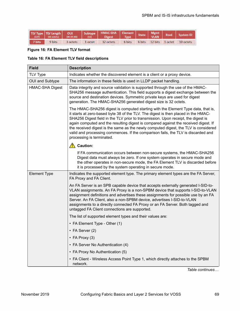
Figure 16: FA Element TLV format
Table 16: FA Element TLV field descriptions
Field DescriptionTLV Type Indicates whether the discovered element is a client or a proxy device.OUI and Subtype The information in these fields is used in LLDP packet handling.HMAC-SHA Digest Data integrity and source validation is supported through the use of the HMAC-
SHA256 message authentication. This field supports a digest exchange between thesource and destination devices. Symmetric private keys are used for digestgeneration. The HMAC-SHA256 generated digest size is 32 octets.
The HMAC-SHA256 digest is computed starting with the Element Type data, that is,it starts at zero-based byte 38 of the TLV. The digest is then placed in the HMAC-SHA256 Digest field in the TLV prior to transmission. Upon receipt, the digest isagain computed and the resulting digest is compared against the received digest. Ifthe received digest is the same as the newly computed digest, the TLV is consideredvalid and processing commences. If the comparison fails, the TLV is discarded andprocessing is terminated.
Caution:
If FA communication occurs between non-secure systems, the HMAC-SHA256Digest data must always be zero. If one system operates in secure mode andthe other operates in non-secure mode, the FA Element TLV is discarded beforeit is processed by the system operating in secure mode.
Element Type Indicates the supported element type. The primary element types are the FA Server,FA Proxy and FA Client.
An FA Server is an SPB capable device that accepts externally generated I-SID-to-VLAN assignments. An FA Proxy is a non-SPBM device that supports I-SID-to-VLANassignment definitions and advertises these assignments for possible use by an FAServer. An FA Client, also a non-SPBM device, advertises I-SID-to-VLANassignments to a directly connected FA Proxy or an FA Server. Both tagged anduntagged FA Client connections are supported.
The list of supported element types and their values are:
• FA Element Type - Other (1)
• FA Server (2)
• FA Proxy (3)
• FA Server No Authentication (4)
• FA Proxy No Authentication (5)
• FA Client - Wireless Access Point Type 1, which directly attaches to the SPBMnetwork.
Table continues…
SPBM and IS-IS infrastructure fundamentals
November 2019 Configuring Fabric Basics and Layer 2 Services for VOSS 69

Field Description• FA Client - Wireless Access Point Type 2, which is tunneled to a controller.
• FA Client - Switch (8)
• FA Client - Router (9)
• FA Client - IP Phone (10)
• FA Client - IP Camera (11)
• FA Client - IP Video (12)
• FA Client - Security Device (13)
• FA Client – Virtual Switch (14)
• FA Client – Server/Endpoint (15)State Indicates the link tagging requirements in FA Client-sourced frames. This field also
indicates the current provisioning mode.
The Link VLAN Tagging bit (bit 1) has one of the following values:
• 0 — indicates that all traffic on the link is tagged. In this case, all discovered FAClients are treated as tagged.
• 1 — indicates that traffic on the link is either tagged or untagged. Here, alldiscovered FA Clients are treated as untagged.
The automatic provisioning mode bits (bits 2 and 3) always have the value 1 for SPBprovisioning. The switch only supports the SPB provisioning mode.
Mgmt VLAN When you configure a management VLAN on the FA Server, it is included in this fieldin FA Server or FA Proxy sourced frames, and is used to support management VLANauto-configuration on the downstream proxy and client devices.
System ID This field contains connection information that a TLV recipient can use to enforceconnectivity restrictions.
It contains the system MAC address (6 octets) for MLT configurations and the virtualBMAC address for vIST and SMLT configurations. It also contains information on theconnection type such as MLT or SMLT.
Limitations• The FA Element TLV exists only once in an LLDP PDU and is included in all PDUs when the
FA service is enabled.• The maximum length of the FA Element TLV is 56 bytes.
FA I-SID-to-VLAN Assignment TLVThe FA I-SID-to-VLAN Assignment TLV is used by FA Clients to distribute I-SID-to-VLANassignments that need to be supported by an FA Proxy or an FA Server.
Figure 17: FA Assignment TLV format
SPBM and IS-IS infrastructure configuration
November 2019 Configuring Fabric Basics and Layer 2 Services for VOSS 70
FA I-SID-to-VLAN Assignment TLV fieldsSome fields are common to both the FA Element and FA Assignment TLVs. The following fields arespecific only to the FA Assignment TLV.
TLV Field DescriptionHMAC-SHA Digest The HMAC-SHA256 digest is computed for the series 1 to 94 of I-SID-to-VLAN
assignments, that is, the data for the digest computation starts at zero-based byte 38of the TLV. The digest is then placed in the HMAC-SHA256 Digest field in the TLVprior to transmission. Upon receipt, the digest is again computed for the series 1 to94 of I-SID-to-VLAN assignments in the received TLV and the resulting digest iscompared against the received digest. If the received digest is the same as the newlycomputed digest, the TLV is considered valid and processing can commence. If thecomparison fails, the TLV is discarded and processing is terminated.
Caution:
If FA communication occurs between non-secure systems, the HMAC-SHA256Digest data must always be zero. If one system operates in secure mode andthe other operates in non-secure mode, the FA I-SID-toVLAN Assignment TLVis discarded before it is processed by the system operating in secure mode.
Assignment status Indicates whether the FA Server accepted or rejected the I-SID-to-VLAN mappingrequest from a client or proxy device.
VLAN Indicates the C-VID value advertised by the client or proxy device in the FA I-SID-to-VLAN mapping request.
I-SID Indicates the I-SID that is advertised by a client or proxy device in the FA I-SID-to-VLAN mapping request. This I-SID is used to create a Switched UNI (ELAN) I-SID.
Note:
This I-SID cannot be used by IPVPN, MVPN, SPBM dynamic multicast range,or Transparent Port UNI.
Limitations• The FA I-SID-to-VLAN Assignment TLV is included in an LLDP PDU only if the FA Server and
proxy or client devices are directly connected to each other.• This TLV can exist only once in an LLDP PDU.• The size limit of this TLV is 511 bytes. This limits the maximum number of I-SID-to-VLAN
assignments supported in an LLDP PDU to 94.• For an FA I-SID-to-VLAN Assignment TLV to be processed, the FA Element TLV must also be
present in the LLDP PDU.
FA Element DiscoveryThe first stage of establishing FA connectivity is element discovery.
On an FA Server, FA is enabled globally by default. However, you must explicitly enable FA on adesired port or MLT interface. After FA is enabled, the FA Server begins transmitting LLDP PDUsthat contain the element discovery TLVs. This information is received by FA Client and FA Proxydevices which in turn also transmit their FA capabilities and settings. After the element handshake
SPBM and IS-IS infrastructure fundamentals
November 2019 Configuring Fabric Basics and Layer 2 Services for VOSS 71

completes, the FA Server receives I-SID-to-VLAN assignment mappings from the connected clientor proxy devices.
An FA Server can communicate with multiple different FA Client and FA Proxy devices.
FA data processingIn the following FA deployment, a client device (Client 1) attaches to the FA Server (FA Server 1)using a proxy device. Another client device (Client 2) attaches to the FA Server (FA Server 2) at theother edge of the network. The following section describes how data is processed when data trafficis transmitted from Client 1 to Client 2.
When Client 1 successfully attaches to FA Server 1, FA Server 1 creates a unique I-SID-to-VLANmapping for Client 1 on its device. This mapping contains the I-SID and C-VID advertised by Client1, using the FA Assignment TLV. For example, assume that Client 1 advertises I-SID 200 and C-VID250.
Similarly, when Client 2 attaches to FA Server 2, FA Server 2 creates an I-SID-to-VLAN mapping forClient 2 on its device with, for example, I-SID 200 and C-VID 100. This is depicted in the followingfigure.
Figure 18: Learning of I-SID-to-VLAN mappings
When data traffic ingresses FA Server 1 at the FA-enabled port 1/1, it contains the C-VID of Client 1,which is, 250. The data is VLAN-encapsulated at this stage. As traffic egresses FA Server 1 into theSPB cloud, it is encapsulated with the ELAN I-SID created on FA Server 1 on behalf of Client 1, thatis I-SID 200. The traffic is now MiM encapsulated with I-SID 200.
The following figure depicts VLAN encapsulation of data traffic from the FA Client to the FA Server(at either end of the SPB cloud) and its MiM encapsulation as it traverses the SPB cloud.
Figure 19: Data encapsulation — VLAN encapsulation and MiM encapsulation
SPBM and IS-IS infrastructure configuration
November 2019 Configuring Fabric Basics and Layer 2 Services for VOSS 72
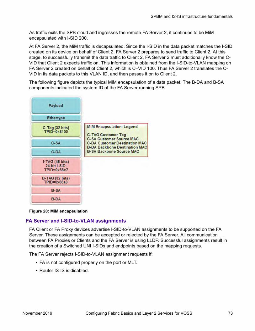
As traffic exits the SPB cloud and ingresses the remote FA Server 2, it continues to be MiMencapsulated with I-SID 200.
At FA Server 2, the MiM traffic is decapsulated. Since the I-SID in the data packet matches the I-SIDcreated on its device on behalf of Client 2, FA Server 2 prepares to send traffic to Client 2. At thisstage, to successfully transmit the data traffic to Client 2, FA Server 2 must additionally know the C-VID that Client 2 expects traffic on. This information is obtained from the I-SID-to-VLAN mapping onFA Server 2 created on behalf of Client 2, which is C–VID 100. Thus FA Server 2 translates the C-VID in its data packets to this VLAN ID, and then passes it on to Client 2.
The following figure depicts the typical MiM encapsulation of a data packet. The B-DA and B-SAcomponents indicated the system ID of the FA Server running SPB.
Figure 20: MiM encapsulation
FA Server and I-SID-to-VLAN assignmentsFA Client or FA Proxy devices advertise I-SID-to-VLAN assignments to be supported on the FAServer. These assignments can be accepted or rejected by the FA Server. All communicationbetween FA Proxies or Clients and the FA Server is using LLDP. Successful assignments result inthe creation of a Switched UNI I-SIDs and endpoints based on the mapping requests.
The FA Server rejects I-SID-to-VLAN assignment requests if:
• FA is not configured properly on the port or MLT.
• Router IS-IS is disabled.
SPBM and IS-IS infrastructure fundamentals
November 2019 Configuring Fabric Basics and Layer 2 Services for VOSS 73

Note:
For Fabric Attach to operate properly and for the FA Server to accept I-SID-to-VLANassignment requests, IS-IS must be enabled.
The following error message is logged immediately after IS-IS is disabled, and appearsonly once in the log file. It does not appear again when an assignment request is madefrom the FA Proxy.
CP1 [12/04/15 00:33:49.733:UTC] 0x00374589 00000000 GlobalRouter FAINFO Fabric Attach Assignments will be rejected since ISIS isdisabled.
• The C-VID and I-SID are not within the supported range.
Different hardware platforms support different customer C-VID ranges. The value 4095 is notsupported. The value 4096 indicates that the port is untagged. An I-SID value of 0 is notsupported on the FA Server.
• The I-SID is already assigned to an IP VPN.
The system displays the error message I-SID is already assigned to an IPVPN.
• The I-SID is already in use for SPB multicast.
The system displays the error message SPB Multicast is enabled, ISID 16000000and greater reserved for dynamic data-isid's used to carry Multicasttraffic over SPB.
• The I-SID has a value that is reserved for internal use.
• The I-SID cannot be used in an IS-IS accept policy.
• The I-SID is associated with a platform VLAN and that VLAN is used as a private VLAN (that is,has a secondary VLAN specified).
• The I-SID is already in use for Transparent Port UNI.
• The port that receives the I-SID-to-VLAN assignment is a member of an MLT, but FA is notsuccessfully enabled on that MLT interface.
• There is a resource error on the FA Server system, such as lack of memory.
• The number of I-SID-to-VLAN assignments on a port exceeds the maximum limit which is 94.
• The number of I-SIDs on the switch exceeds the maximum limit.
• The same endpoint is configured on more than one I-SID.
• The port or MLT is associated with more than one C-VID in the same I-SID.
When the FA Server rejects I-SID-to-VLAN assignments, aside from viewing the log file, you canuse trace to troubleshoot the cause of rejection.
For an example on troubleshooting rejection of I-SID-to-VLAN assignments on the FA Server and formore information on using trace, see Troubleshooting VOSS.
SPBM and IS-IS infrastructure configuration
November 2019 Configuring Fabric Basics and Layer 2 Services for VOSS 74
FA managementYou can configure a management I-SID on an FA-enabled port or MLT. This I-SID includes anoptional C-VID parameter, which is a VLAN ID that is locally significant to the port or MLT and doesnot represent a platform VLAN.
Depending on whether the C-VID value is specified, the behavior is as follows:
• If the C-VID value is specified, the FA Server transmits this VLAN ID as the management VLANin the FA Element TLV. A client or proxy receiving this TLV uses this VLAN ID for managementtraffic on the FA Server uplink.
Different hardware platforms support different customer C-VID ranges.
• If the C-VID value is not specified, the FA Server transmits a management VLAN with a VLANID value of 4095 in the FA Element TLV. A client or proxy receiving this TLV uses untaggedtraffic for network management on the FA Server uplink.
If you do not configure a management I-SID, the FA Server transmits a management VLAN ID valueof 0 in the FA Element TLV. A client/proxy that receives the FA Element TLV retains the initialmanagement configuration (if any) on its device.
Limitations of FA management I-SIDs• A management I-SID value of 0 is not supported on the FA Server.• You cannot enable BPDU on a management I-SID.
FA management configuration considerationsA Switched UNI I-SID that is created when an FA assignment is learned on a port or MLT, isuniquely identified by a tuple comprising of one of the combinations of (port, I-SID and C-VID) or(MLT ID, I-SID and C-VID). When you configure FA management, similar tuples are used. You canconfigure FA management on an FA-enabled port or MLT on which FA assignment mappings arelearned, as long as the FA management tuple exactly matches the tuple created by the learned FAmapping.The following scenarios describe the behavior when you configure FA management on a port orMLT that also receives learned FA mappings, but the tuples do not match.
• Scenario 1: You attempt to configure FA management on a port or MLT where an FAassignment mapping is already learned.For example, consider an FA-enabled port 1/1 on which an assignment mapping is learned,with I-SID 100 and C-VID 20. You can configure FA management on port 1/1 as long as the I-SID and C-VID values exactly match that of the learned FA mapping. However, if you attemptto configure FA management on the port with a different I-SID and C-VID value, theconfiguration is not successful and an error message displays.
• Scenario 2: An FA assignment mapping is learned on a port or MLT that already has FAmanagement configured.For example, consider that FA management is configured on port 1/1. If an FA assignmentmapping is learned on the port with the same I-SID and C-VID values as that of the FAmanagement configuration, then the mapping is accepted. Otherwise the mapping is rejected.
SPBM and IS-IS infrastructure fundamentals
November 2019 Configuring Fabric Basics and Layer 2 Services for VOSS 75

FA message authentication and integrity protectionFor the security of FA communication in terms of data integrity and authenticity, a keyed-hashmessage authentication code can be transmitted within every FA TLV.
It protects the I-SID-to-VLAN assignment exchanges between the FA Server and FA Proxy. Thestandard HMAC-SHA256 algorithm calculates the message authentication code (digest) involving acryptographic hash function (SHA-256) in combination with a shared secret key. The key issymmetric, that is, it is known by both the source and destination parties.
By default, on the FA Server, message authentication is enabled at the interface level and a defaultkey is defined to provide secure communication.
You can configure a different authentication key on an interface (port or MLT) on the FA Server, toauthenticate a client on that interface. The authentication key is stored in encrypted form when yousave configuration on the FA Server. For an FA Client to authenticate and attach to the FA Server,the authentication key must match on both the client and the server. In general, the FAauthentication key must match between two FA components exchanging FA TLVs through LLDP.
When you enable FA message authentication, the message authentication key (default orconfigured) generates a Hash-based Message Authentication Code (HMAC) digest that is includedin FA I-SID-to-VLAN Assignment TLV. Upon receipt, the HMAC digest is recomputed for the TLVdata and compared against the digest included in the TLV. If the digests are the same, the data isvalid. If the digests are not the same, the data is considered invalid and is ignored.
The FA secure communication setting (enabled/disabled) and the symmetric key data aremaintained across resets and restored during FA initialization.
Fabric Attach and Switched UNIWith the C-VLAN UNI feature, I-SID-to-VLAN mappings must be unique across the network. Withthe Transparent Port UNI (ELAN Transparent) feature, you can map an entire port or MLT to an I-SID.
With the Switched UNI feature, you can associate many different C-VID/port or C-VID/MLT listcombinations to a single I-SID.
Switched UNI and FAFA brings the capability of automatically creating Switched UNI I-SIDs on a switch, without manualintervention. The I-SIDs thus created are ELAN I-SIDs with endpoints of type Switched UNI, and areby default for Layer 2. MAC learning takes place and there is an any-to-any relationship. For Layer 3participation, you must configure a platform VLAN with the same I-SID value as that of the I-SID in alearned FA mapping.
Note:The number of Switched UNI I-SIDs created are different for different product families. For moreinformation, see Release Notes for VOSS.
Limitations of FA-created Switched UNI I-SIDs• An FA-created Switched UNI I-SID is always ELAN.• You cannot enable BPDU on an FA-created Switched UNI I-SID.
SPBM and IS-IS infrastructure configuration
November 2019 Configuring Fabric Basics and Layer 2 Services for VOSS 76
• The ELAN I-SIDs created are by default for Layer 2. For Layer 3 participation, you mustmanually configure a platform VLAN with the same I-SID value as that of the I-SID in a learnedFA mapping. You can configure the platform VLAN with the same VLAN ID as that of the C-VID, or use a different value.
• The Switched UNI (ELAN) I-SID cannot be used by IPVPN, MVPN, SPBM dynamic multicastrange, or a T-UNI.
• You cannot change from one UNI type to another dynamically. The I-SID must be deleted andcreated with the new UNI type (Customer VLAN (C-VLAN), Transparent Port user-network-interface (T-UNI), ELAN).
• If the port is a member of an MLT, you must add the entire MLT to the C-VID.• The port is always in the forwarding state.• You cannot associate a port or MLT with more than one C-VID in the same I-SID.• The same C-VID, port or MLT cannot be a member of more than one I-SID. Different hardware
platforms support different customer C-VID ranges. The value 4095 is not supported andcannot be configured. The value 4096 indicates that the port is untagged.
• An I-SID value of 0 is not supported on the FA Server.
Fabric Attach deployment scenariosFabric Attach is typically deployed in the access layer(s) of a Fabric Connect network.
Fabric Attach, when used with a Fabric Connect solution, provides the same capabilities at theaccess layer, but those services and policies are now mapped across the entire network end-to-end.FA makes user and end device attachment simple and creates network configuration and sets upresources only when needed.
An FA Server can be connected to FA Client or FA Proxy devices on three types of interfaces,namely, a port, MLT or an SMLT. The following sections discuss FA in SMLT and non-SMLTdeployments.
FA and Switched UNI in non-SMLT deploymentsThe following deployment shows an SPBM network in which one edge has manually configuredSwitched UNI I-SIDs and the other edge has Fabric Attach (FA). At the FA edge, the I-SIDs arelearned using FA TLVs and are automatically created on the FA Server as ELAN I-SIDs withSwitched UNI endpoints.This deployment demonstrates that the FA-created I-SIDs can communicate with any other I-SID(manually created Switched UNI or a C-VLAN with an I-SID), on the local switch or across theSPBM fabric, as long as the I-SID values are the same.
SPBM and IS-IS infrastructure fundamentals
November 2019 Configuring Fabric Basics and Layer 2 Services for VOSS 77

BEB-B is a switch acting as the FA Server with an NNI interface to the SPBM cloud. FA Client andFA Proxy devices send I-SID-to-VLAN mapping requests to the FA Server on the respective FA-enabled ports, using LLDP TLVs. This enables the I-SID endpoints to communicate with the SPBcloud.If several clients are aggregated in an MLT, at least one of the ports must send the mappingrequests for the FA Server to create the I-SID endpoints for that MLT. For example, let Client 2 be awireless FA Client (such as an WLAN 9100 AP device) on port 1/21, that sends an FA mappingrequest for I-SID 100 and C-VID (VLAN ID) 100. The FA Server (BEB-B) creates the requested I-SID 100 on its device, and advertises it to the SPB cloud.BEB-A has manually configured Switched UNI endpoints, one of which is Client 1 (connected at port1/1) using the same I-SID value 100.With this setup, data traffic can freely flow between Client 1 and Client 2 through the two BEBs andthe BCB.Thus the Switched UNI I-SIDs learned using FA TLVs on one edge of the Fabric Connect (SPBM)network can communicate with the manually created I-SIDs on the other edge, as long as they bothhave the same value.
FA and Switched UNI in SMLT deploymentsThe following examples discuss FA in dual-homed and single-homed SMLT deployments.Fabric Attach in a dual-homed SMLT deploymentThe following section describes FA in a dual-homed SMLT deployment. A pair of switches thatoperate as IST peers act as the FA Server. An FA Proxy (typically a wiring closet switch or anaccess switch) is connected to FA Clients and in turn to end devices. The FA Clients or FA Proxiesadvertise I-SID-to-VLAN mappings namely the interface C-VID and the I-SID to the FA Serverswitches. Both switches receive the mapping information using LLDP TLVs. The switch that learnsthe mapping first from the LLDP TLV considers the I-SID endpoint to be discovered locally, andcreates the I-SID on its device. It then sends the mapping information to its peer switch. When thepeer switch receives the mapping across IST in a new SMLT message, it too creates the I-SID andendpoint on its device. This I-SID however, is considered to be discovered remotely, because thedata was synchronized from its peer.
Note:• For the peer switches acting as the FA Server to transmit the same FA System ID (based
on the virtual MAC), SMLT configuration must be the same on both peers.
SPBM and IS-IS infrastructure configuration
November 2019 Configuring Fabric Basics and Layer 2 Services for VOSS 78
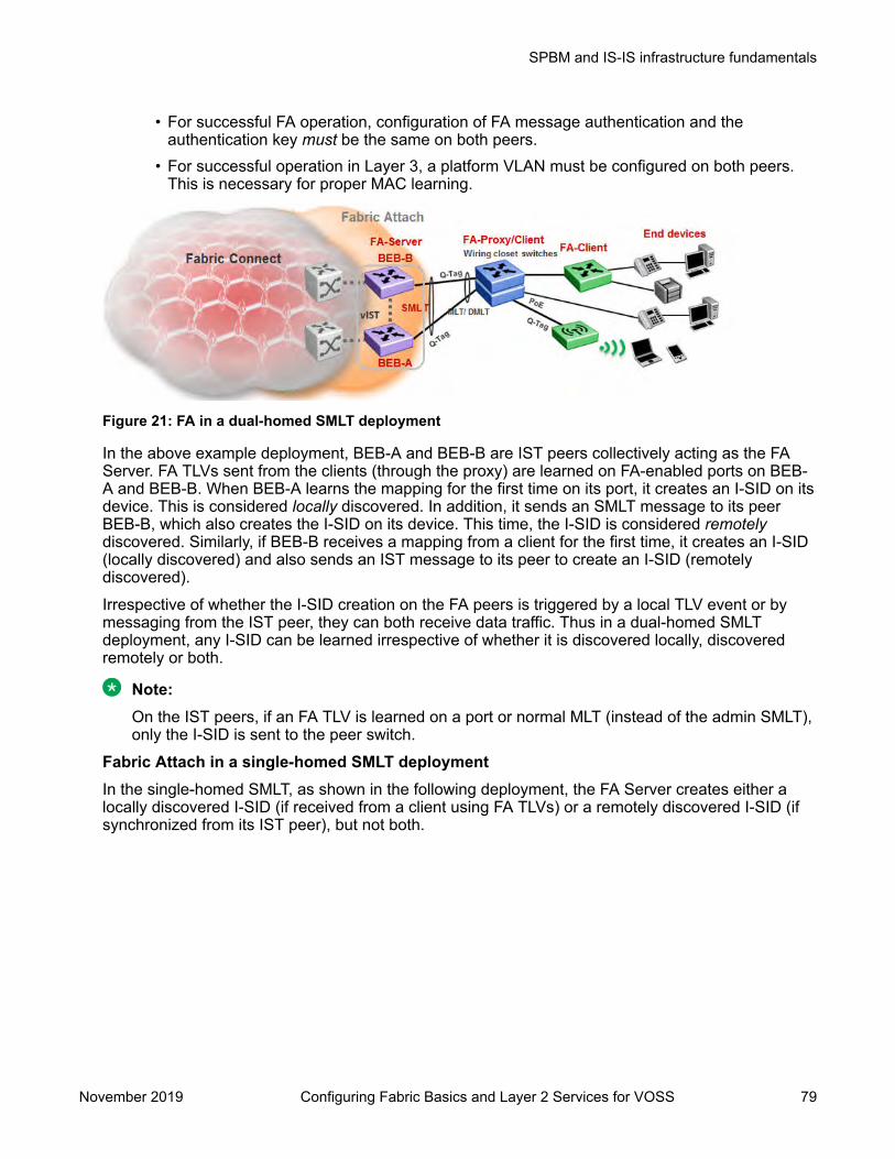
• For successful FA operation, configuration of FA message authentication and theauthentication key must be the same on both peers.
• For successful operation in Layer 3, a platform VLAN must be configured on both peers.This is necessary for proper MAC learning.
Figure 21: FA in a dual-homed SMLT deployment
In the above example deployment, BEB-A and BEB-B are IST peers collectively acting as the FAServer. FA TLVs sent from the clients (through the proxy) are learned on FA-enabled ports on BEB-A and BEB-B. When BEB-A learns the mapping for the first time on its port, it creates an I-SID on itsdevice. This is considered locally discovered. In addition, it sends an SMLT message to its peerBEB-B, which also creates the I-SID on its device. This time, the I-SID is considered remotelydiscovered. Similarly, if BEB-B receives a mapping from a client for the first time, it creates an I-SID(locally discovered) and also sends an IST message to its peer to create an I-SID (remotelydiscovered).Irrespective of whether the I-SID creation on the FA peers is triggered by a local TLV event or bymessaging from the IST peer, they can both receive data traffic. Thus in a dual-homed SMLTdeployment, any I-SID can be learned irrespective of whether it is discovered locally, discoveredremotely or both.
Note:On the IST peers, if an FA TLV is learned on a port or normal MLT (instead of the admin SMLT),only the I-SID is sent to the peer switch.
Fabric Attach in a single-homed SMLT deploymentIn the single-homed SMLT, as shown in the following deployment, the FA Server creates either alocally discovered I-SID (if received from a client using FA TLVs) or a remotely discovered I-SID (ifsynchronized from its IST peer), but not both.
SPBM and IS-IS infrastructure fundamentals
November 2019 Configuring Fabric Basics and Layer 2 Services for VOSS 79

Figure 22: Fabric Attach in a single-homed SMLT deployment
Fabric Attach ConsiderationsReview the following restrictions, limitations, and behavioral characteristics for Fabric Attach.
• IS-IS and FA must be globally enabled on the FA Server, for FA to operate successfully.
• Static MAC, Static ARP and configuration of a static IGMP group are not supported on FA-enabled ports.
• An FA port cannot be a BROUTER port.
• You cannot enable FA on an existing Flex UNI, Transparent Port UNI, or a C-VLAN UNI port.
• FA I-SID-to-VLAN assignment mapping requests from a client or proxy device can be acceptedor rejected by the FA Server.
• On an FA-enabled port or MLT, you must first disable LACP before you change the LACP key.
• You can only enable VLACP on an FA enabled MLT; VLACP is not supported on FA enablednon-MLT ports.
• On VLACP enabled ports, FA and LLDP signaling run independent of the VLACP state.Therefore, requests and responses are exchanged between the FA Server and client or proxydevices even if VLACP is operationally down. However, forwarding of data traffic is dependenton VLACP being operationally up on the port.
For example, if VLACP is enabled on the FA Server side of the link but not on the proxy or theclient side, the FA Server learns the I-SID-to-VLAN assignment mappings and creates therequired I-SIDs on its device. However, data traffic is not forwarded on the port until VLACP isoperationally up.
• You cannot use a port designated as a Fabric Extend tunnel source (configured using thecommand ip-tunnel-source-address), for Fabric Attach. This limitation applies to theVSP 4000 Series only.
SPBM and IS-IS infrastructure configuration
November 2019 Configuring Fabric Basics and Layer 2 Services for VOSS 80

• FA uses the virtual MAC to create the FA system ID when the FA is on an SMLT. If you deletethe SPBM instance, then this information is no longer available. Therefore, you must delete theFA on SMLT before deleting the SPBM instance.
Endpoint TrackingNote:
DEMO FEATURE - Endpoint Tracking is a demonstration feature. Demonstration features areprovided for testing purposes. Demonstration features are for lab use only and are not for use ina production environment.
Table 17: Endpoint Tracking product support
Feature Product Release introducedEndpoint Tracking
Note:
DEMO FEATURE - EndpointTracking is a demonstrationfeature. Demonstrationfeatures are provided fortesting purposes.Demonstration features arefor lab use only and are notfor use in a productionenvironment.
VSP 4450 Series Not SupportedVSP 4900 Series Not SupportedVSP 7200 Series VOSS 8.1VSP 7400 Series VOSS 8.1VSP 8200 Series VOSS 8.1VSP 8400 Series VOSS 8.1VSP 8600 Series Not SupportedXA1400 Series Not Supported
Endpoint Tracking OverviewEndpoint Tracking provides dynamic assignment of virtual machines (VMs) to IP subnets as theyattach to a Shortest Path Bridging (SPB) cloud. Deployment scenarios include VMs connecting toDvR Leaf nodes, or regular SPBM deployments.Extreme Management Center is integral to the Endpoint Tracking solution. Extreme ManagementCenter's ExtremeConnect module integrates with third-party virtualization software (such asVMware or Microsoft HyperV) and communicates with the ExtremeControl module, which providesthe RADIUS authorization functionality.When the switch detects a new VM on a port, it sends a RADIUS request to Extreme ManagementCenter. ExtremeConnect checks with VCenter for the Port Group, VLAN ID, and I-SID informationthat corresponds with the VM, communicates with the ExtremeControl module for the RADIUSauthentication, and sends the RADIUS response back to the switch with the VLAN:I-SID bindinginformation. Based on the binding, the switch then automatically creates a dynamic Switched UNI(S-UNI). Dynamic S-UNIs are not saved into the configuration file.When a VM moves from one port or device in the network to another while maintaining the VLAN:I-SID binding, the older binding (where the MAC was originally learned) is deleted.
SPBM and IS-IS infrastructure fundamentals
November 2019 Configuring Fabric Basics and Layer 2 Services for VOSS 81

Typical Endpoint Tracking Implementation ExampleThe following example shows a typical implementation of Endpoint Tracking and the dynamic I-SIDassignment process, as provisioned in Extreme Management Center.
Figure 23: Endpoint Tracking Example
The sequence within and among the four example VLANs in this configuration is as follows:1. The RADIUS server authenticates VM1, and the switch automatically creates a Switched
UNI with VLAN 10 and I-SID 10 binding, (using the outbound attributes received from theRADIUS server). Subsequently, the server authenticates VM2, which uses the sameSwitched UNI.
2. Similarly, on the other side of the SPB cloud, the RADIUS server authenticates VM5 and theswitch automatically creates a Switched UNI with VLAN 30 and I-SID 10 binding, (using theoutbound attributes received from the RADIUS server). Subsequently, the serverauthenticates VM6, which uses the same Switched UNI.
3. The same sequence occurs for VMs 3 and 4, and PCs 7 and 8, with the first authentication ineach VLAN providing the outbound RADIUS attributes needed for the creation of a SwitchedUNI for that VLAN.
SPBM and IS-IS infrastructure configuration
November 2019 Configuring Fabric Basics and Layer 2 Services for VOSS 82

4. The final result is that VMs 1, 2, 5, and 6 can access each other on I-SID 10, and VMs 3, 4,7, and 8 can access each other on I-SID 20.
Extreme Management Center IntegrationEndpoint Tracking integrates with Extreme Management Center ExtremeConnect andExtremeControl modules. The ExtremeConnect module offers API integration with third partyproducts, such as VMware or Mircrosoft HyperV, from which VM endpoint information is extractedand automatically converted into usable policies for use in the ExtremeControl module, which actsas a RADIUS server for authorizing Endpoint Tracking MACs.The following diagram illustrates an example of Extreme Management Center interaction with aswitch for Endpoint Tracking:
Figure 24: Extreme Management Center Endpoint Tracking Interaction Example
RADIUS Server AttributesThe RADIUS attributes to configure in either standard or custom Extreme Management CenterRADIUS profiles for Endpoint Tracking depend on your deployment and traffic type:
• For tagged traffic, if the RADIUS server provides both the VLAN ID and I-SID value, use onlythe FA-VLAN-ISID attribute.
• For tagged traffic, if the RADIUS server provides only the VLAN ID (and you are thereforeusing an I-SID offset value), use only the Tunnel-Private-Group-ID attribute.
• For untagged traffic, if the RADIUS server provides both the VLAN ID and I-SID value, use theFA-VLAN-ISID and Egress-VLANID or Egress-VLAN-name attributes.
• For untagged traffic, if the RADIUS server provides only the VLAN ID (and you are thereforeusing an I-SID offset value), use the Tunnel-Private-Group-ID and Egress-VLANID orEgress-VLAN-name attributes.
• Use the Session-Timeout attribute to override the default timeout period of 24 hours, whichis amount of time, in seconds, between a MAC address authentication and the deletion of thatMAC address from the Endpoint Tracking binding table.
All other RADIUS attributes are ignored.
RADIUS Dynamic Session Change Support (RFC 5176)Endpoint Tracking uses RADIUS RFC 5176 Disconnect and Change-of-Authorization (CoA)functionality to enable processing of dynamic session changes.For more information about RADIUS Dynamic Session Change Support (RFC 5176), see Configuring Security for VOSS.
SPBM and IS-IS infrastructure fundamentals
November 2019 Configuring Fabric Basics and Layer 2 Services for VOSS 83
Static S-UNIs and Visibility ModeEndpoint Tracking can also be used in cases where static S-UNIs are configured on EndpointTracking-enabled ports. In this case, the MACs are allowed by default on the static S-UNI. However,by default, the MACs learned on a static S-UNI are not learned at the Endpoint Tracking level.Endpoint Tracking Visibility Mode allows tracking of MACs that are learned on static S-UNIs. Thisimplies that a binding is created for these MACs, but these bindings do not create dynamic S-UNIs,they are used for tracking purposes only.
Interface SupportEndpoint Tracking is supported on Ethernet ports, MLTs, and SMLTs.If the switch is a Virtual IST (vIST) peer, the dynamic Switched UNI is synchronized to its vIST peeras follows:
• If the MAC is learned on an SMLT UNI interface, all Switched UNI information is synchronizedto the vIST peer.
• If the MAC is learned on a non-SMLT UNI interface, only the I-SID is synchronized to the vISTpeer.
Operational ConsiderationsConsider the following when implementing Endpoint Tracking:
• A RADIUS server used for Endpoint Tracking provides authorization only; no accountingprocesses are supported. Although accounting is enabled by default for all RADIUS servers, itis not currently supported for use with Endpoint Tracking, even if left enabled.
• Fabric Attach is not supported on ports or MLT/SMLTs that have Endpoint Tracking enabled.
Configuration FundamentalsTo configure Endpoint Tracking, you must perform the following:
Extreme Management Center Configuration• Using the ExtremeConnect component, configure and manage your third-party virtualization
platform.• Using the ExtremeControl component, configure and manage the RADIUS server used for
Endpoint Tracking authentication.For information about configuring Extreme Management Center, see theExtreme ManagementCenter documentation at https://www.extremenetworks.com/support/documentation/.
Switch Configuration• Add, configure, and enable the RADIUS server host as configured in the Extreme Management
Center to function as the switch authentication server for Endpoint Tracking. Ensure that youselect endpoint-tracking for the used-by variable. Add, configure and enable theRADIUS dynamic-server client. For information about adding a RADIUS server host and aRADIUS dynamic-server client to the switch, see Configuring Security for VOSS.
• Optionally configure a global I-SID offset value.When you provision the Endpoint Tracking RADIUS server in Extreme Management Center,you choose which outbound attributes the RADIUS server includes in each authenticationresponse. If you always include an I-SID value in those outbound attributes, you do not need toconfigure an I-SID offset value on the switch.
SPBM and IS-IS infrastructure configuration
November 2019 Configuring Fabric Basics and Layer 2 Services for VOSS 84

For MACs that do not receive an I-SID attribute from the RADIUS server, use Auto-ISID-Offsetfunctionality. The configured I-SID offset value is used to calculate an I-SID value for aswitched UNI when no I-SID value is provided by the RADIUS server in the outboundattributes. In that case, the I-SID value is calculated as follows:
I-SID = VLAN ID + configured I-SID offset value.• After optionally configuring a global I-SID offset value, enable Endpoint Tracking globally on the
switch.• Create and enable Endpoint Tracking on each interface. Ensure that you have deleted any
existing VLAN bindings on the interfaces, as the Endpoint Tracking bindings are dynamic.CLI commands provide the functionality to separate the creation, deletion, enabling, anddisabling of Endpoint Tracking on interfaces. For example, if you want to flush all VLAN:I-SIDbindings on a port, you can disable (but not delete) Endpoint Tracking on that port, keeping theport distinct from other ports where Endpoint Tracking is not yet created.
IS-IS external metricThe software supports the IS-IS external metric to differentiate between internal and external routeswith Accept Policies.
With this feature you can use IS-IS to:• change the external metric-type of a route when redistributing it from another protocol to IS-IS
through route redistribution using a route-map.• change the external metric-type of a route when accepting a remote IS-IS route with the help of
IS-IS accept policies using a route-map.• match the external metric-type when redistributing IS-IS routes into other protocols using the
match option in the route-map.• match the external metric-type when accepting a remote IS-IS route with the help of IS-IS
accept policies by using a route-map• process the external metric-type in the route selection process.
The IS-IS metric type can also be set using the base redistribute command without using the route-map.
SPB EthertypeThe switch aligns the SPB ethertype to BCB's locally configured SPB ethertype. The BCBs mark theBTAG Ethertype of a transit MAC-in-MAC packet to match its locally configured value when it exitson a different NNI port, even if the BTAG Ethertype on the incoming packet (CFM or SPB) does notmatch its configured value.
SPBM and IS-IS infrastructure fundamentals
November 2019 Configuring Fabric Basics and Layer 2 Services for VOSS 85
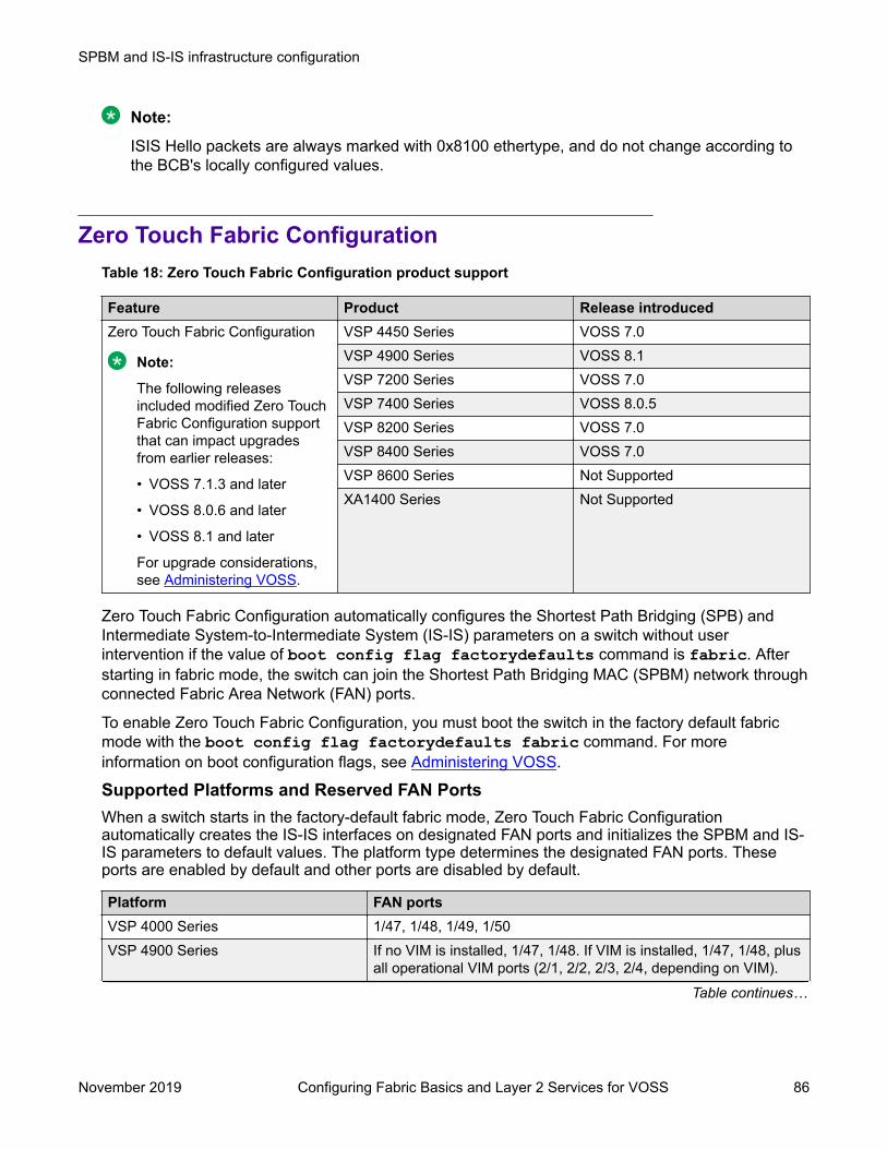
Note:
ISIS Hello packets are always marked with 0x8100 ethertype, and do not change according tothe BCB's locally configured values.
Zero Touch Fabric ConfigurationTable 18: Zero Touch Fabric Configuration product support
Feature Product Release introducedZero Touch Fabric Configuration
Note:
The following releasesincluded modified Zero TouchFabric Configuration supportthat can impact upgradesfrom earlier releases:
• VOSS 7.1.3 and later
• VOSS 8.0.6 and later
• VOSS 8.1 and later
For upgrade considerations,see Administering VOSS.
VSP 4450 Series VOSS 7.0VSP 4900 Series VOSS 8.1VSP 7200 Series VOSS 7.0VSP 7400 Series VOSS 8.0.5VSP 8200 Series VOSS 7.0VSP 8400 Series VOSS 7.0VSP 8600 Series Not SupportedXA1400 Series Not Supported
Zero Touch Fabric Configuration automatically configures the Shortest Path Bridging (SPB) andIntermediate System-to-Intermediate System (IS-IS) parameters on a switch without userintervention if the value of boot config flag factorydefaults command is fabric. Afterstarting in fabric mode, the switch can join the Shortest Path Bridging MAC (SPBM) network throughconnected Fabric Area Network (FAN) ports.
To enable Zero Touch Fabric Configuration, you must boot the switch in the factory default fabricmode with the boot config flag factorydefaults fabric command. For moreinformation on boot configuration flags, see Administering VOSS.
Supported Platforms and Reserved FAN PortsWhen a switch starts in the factory-default fabric mode, Zero Touch Fabric Configurationautomatically creates the IS-IS interfaces on designated FAN ports and initializes the SPBM and IS-IS parameters to default values. The platform type determines the designated FAN ports. Theseports are enabled by default and other ports are disabled by default.
Platform FAN portsVSP 4000 Series 1/47, 1/48, 1/49, 1/50VSP 4900 Series If no VIM is installed, 1/47, 1/48. If VIM is installed, 1/47, 1/48, plus
all operational VIM ports (2/1, 2/2, 2/3, 2/4, depending on VIM).
Table continues…
SPBM and IS-IS infrastructure configuration
November 2019 Configuring Fabric Basics and Layer 2 Services for VOSS 86
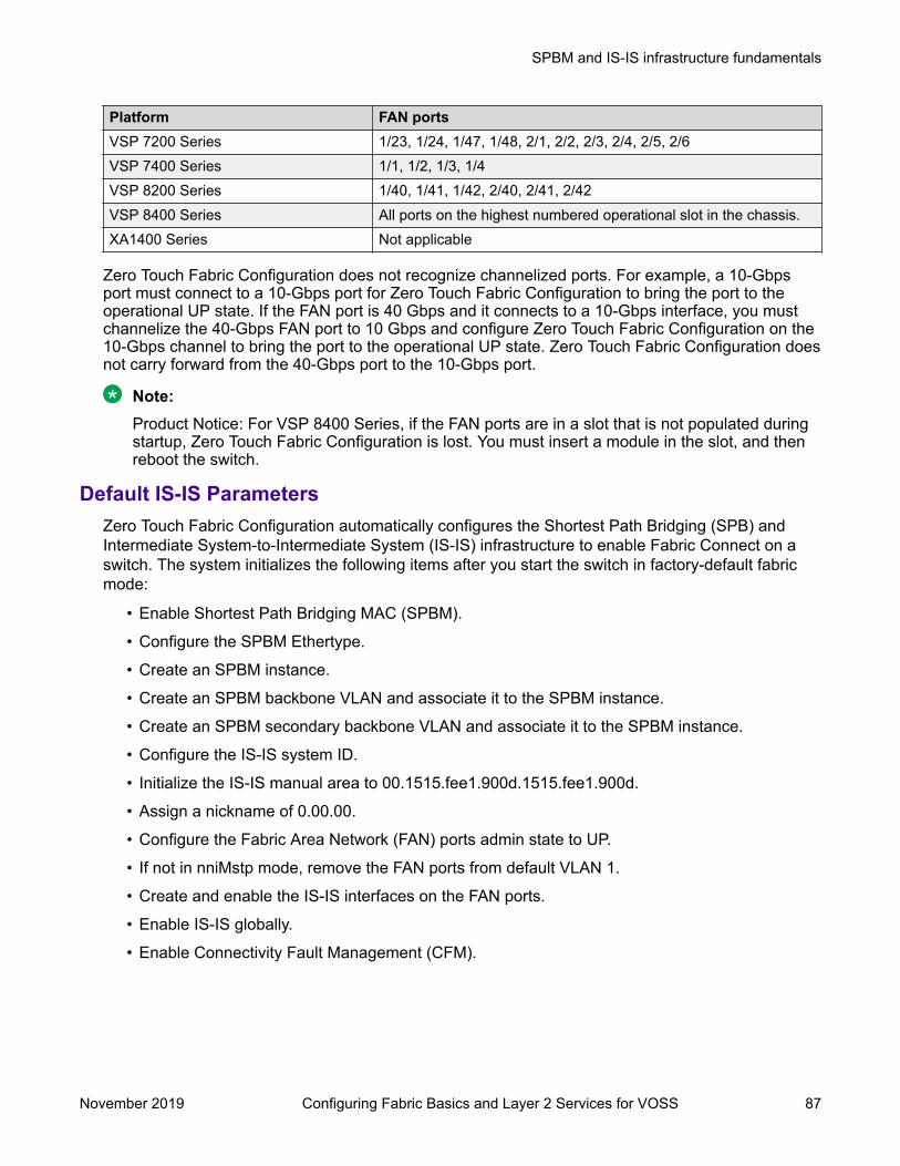
Platform FAN portsVSP 7200 Series 1/23, 1/24, 1/47, 1/48, 2/1, 2/2, 2/3, 2/4, 2/5, 2/6VSP 7400 Series 1/1, 1/2, 1/3, 1/4VSP 8200 Series 1/40, 1/41, 1/42, 2/40, 2/41, 2/42VSP 8400 Series All ports on the highest numbered operational slot in the chassis.XA1400 Series Not applicable
Zero Touch Fabric Configuration does not recognize channelized ports. For example, a 10-Gbpsport must connect to a 10-Gbps port for Zero Touch Fabric Configuration to bring the port to theoperational UP state. If the FAN port is 40 Gbps and it connects to a 10-Gbps interface, you mustchannelize the 40-Gbps FAN port to 10 Gbps and configure Zero Touch Fabric Configuration on the10-Gbps channel to bring the port to the operational UP state. Zero Touch Fabric Configuration doesnot carry forward from the 40-Gbps port to the 10-Gbps port.
Note:Product Notice: For VSP 8400 Series, if the FAN ports are in a slot that is not populated duringstartup, Zero Touch Fabric Configuration is lost. You must insert a module in the slot, and thenreboot the switch.
Default IS-IS ParametersZero Touch Fabric Configuration automatically configures the Shortest Path Bridging (SPB) andIntermediate System-to-Intermediate System (IS-IS) infrastructure to enable Fabric Connect on aswitch. The system initializes the following items after you start the switch in factory-default fabricmode:
• Enable Shortest Path Bridging MAC (SPBM).
• Configure the SPBM Ethertype.
• Create an SPBM instance.
• Create an SPBM backbone VLAN and associate it to the SPBM instance.
• Create an SPBM secondary backbone VLAN and associate it to the SPBM instance.
• Configure the IS-IS system ID.
• Initialize the IS-IS manual area to 00.1515.fee1.900d.1515.fee1.900d.
• Assign a nickname of 0.00.00.
• Configure the Fabric Area Network (FAN) ports admin state to UP.
• If not in nniMstp mode, remove the FAN ports from default VLAN 1.
• Create and enable the IS-IS interfaces on the FAN ports.
• Enable IS-IS globally.
• Enable Connectivity Fault Management (CFM).
SPBM and IS-IS infrastructure fundamentals
November 2019 Configuring Fabric Basics and Layer 2 Services for VOSS 87
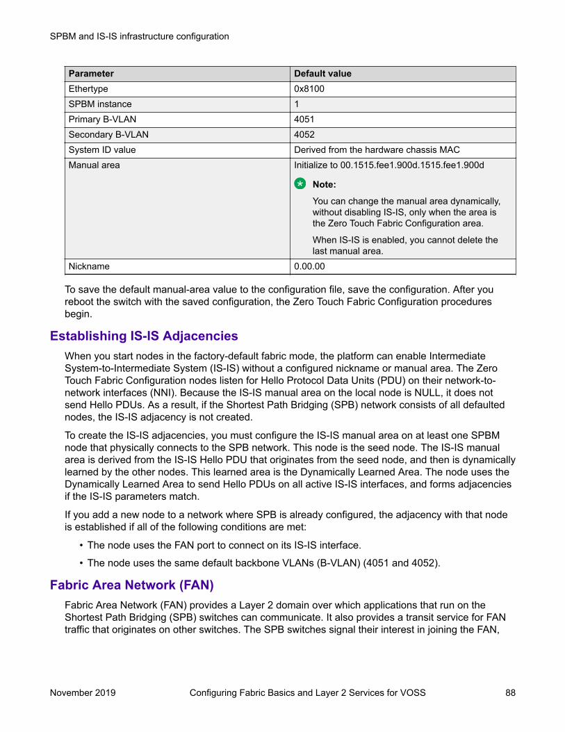
Parameter Default valueEthertype 0x8100SPBM instance 1Primary B-VLAN 4051Secondary B-VLAN 4052System ID value Derived from the hardware chassis MACManual area Initialize to 00.1515.fee1.900d.1515.fee1.900d
Note:
You can change the manual area dynamically,without disabling IS-IS, only when the area isthe Zero Touch Fabric Configuration area.
When IS-IS is enabled, you cannot delete thelast manual area.
Nickname 0.00.00
To save the default manual-area value to the configuration file, save the configuration. After youreboot the switch with the saved configuration, the Zero Touch Fabric Configuration proceduresbegin.
Establishing IS-IS AdjacenciesWhen you start nodes in the factory-default fabric mode, the platform can enable IntermediateSystem-to-Intermediate System (IS-IS) without a configured nickname or manual area. The ZeroTouch Fabric Configuration nodes listen for Hello Protocol Data Units (PDU) on their network-to-network interfaces (NNI). Because the IS-IS manual area on the local node is NULL, it does notsend Hello PDUs. As a result, if the Shortest Path Bridging (SPB) network consists of all defaultednodes, the IS-IS adjacency is not created.
To create the IS-IS adjacencies, you must configure the IS-IS manual area on at least one SPBMnode that physically connects to the SPB network. This node is the seed node. The IS-IS manualarea is derived from the IS-IS Hello PDU that originates from the seed node, and then is dynamicallylearned by the other nodes. This learned area is the Dynamically Learned Area. The node uses theDynamically Learned Area to send Hello PDUs on all active IS-IS interfaces, and forms adjacenciesif the IS-IS parameters match.
If you add a new node to a network where SPB is already configured, the adjacency with that nodeis established if all of the following conditions are met:
• The node uses the FAN port to connect on its IS-IS interface.
• The node uses the same default backbone VLANs (B-VLAN) (4051 and 4052).
Fabric Area Network (FAN)Fabric Area Network (FAN) provides a Layer 2 domain over which applications that run on theShortest Path Bridging (SPB) switches can communicate. It also provides a transit service for FANtraffic that originates on other switches. The SPB switches signal their interest in joining the FAN,
SPBM and IS-IS infrastructure configuration
November 2019 Configuring Fabric Basics and Layer 2 Services for VOSS 88

and the Intermediate System-to-Intermediate System (IS-IS) Shortest Path First (SPF) tree uses aninternal reserved I-SID (16777001) to create a multicast domain for these switches to communicatewith each other. The FAN requires no user configuration.
The Zero Touch Fabric Configuration feature uses the FAN to dynamically learn nicknames. Theseed node distributes this information to the newly added fabric nodes.
A node is a member of the FAN only if applications that run on the node require FAN transport.Dynamic Nickname Assignment server and client are currently the only applications that requireFAN transport. The FAN membership changes when the state of these applications changes. Anode that is not a member of the FAN can act as a Backbone Core Bridge (BCB) for the FAN(16777001) communication.
Zero Touch Fabric Configuration and NicknamesWhen a node starts in factory-default fabric mode to enable Zero Touch Fabric Configuration, thenickname is 0. The node becomes a nickname client because the nickname is not yet configured.The node joins the FAN and starts advertising FAN membership using Type-Length-Value (TLV)147.
To deploy Dynamic Nickname Assignment, select a node, and then enable the nickname server onthat node. After the client detects that a nickname server exists in the network, the client sends arequest to the server for a nickname. The server assigns the nickname and the client node learnsthe nickname.
Important:
When a switch operates without a nickname, the Shortest Path Bridging MAC (SPBM) servicesdo not function, which can cause a disruption to the network; only the FAN transport isoperational. Ensure that a nickname server is active in the SPB network and that the client canreach the server through a path of SPB nodes that all support the FAN transport. Otherwise, theclient is not able to reach the nickname server and obtain a nickname. After the client obtains anickname from the server, the SPB services start.
If you do not want to use Dynamic Nickname Assignment, configure static nicknames on all of thenodes.
FAN TransitFabric Area Network (FAN) transit refers to the ability of a switch to forward traffic between SPBnodes participating in a FAN. The switch is neither a part of the FAN nor does it originate or sinkFAN traffic. It only forwards the traffic between the FAN end-points.
For information on how to verify the functioning of a transit switch within a FAN, see TroubleshootingVOSS.
SPBM and IS-IS infrastructure fundamentals
November 2019 Configuring Fabric Basics and Layer 2 Services for VOSS 89

Dynamic Nickname AssignmentTable 19: Dynamic Nickname Assignment product support
Feature Product Release introducedDynamic Nickname Assignment VSP 4450 Series VOSS 7.0
VSP 4900 Series VOSS 8.1VSP 7200 Series VOSS 7.0VSP 7400 Series VOSS 8.0.5VSP 8200 Series VOSS 7.0VSP 8400 Series VOSS 7.0VSP 8600 Series Not SupportedXA1400 Series Not Supported
Dynamic Nickname Assignment is a service that provides unique nicknames to compatible switchesacross a Fabric Area Network (FAN).
SPBM and IS-IS infrastructure configuration
November 2019 Configuring Fabric Basics and Layer 2 Services for VOSS 90

You can configure a node in a FAN as a nickname server. You must configure the nickname serverwith a static nickname from the nickname allocation range 0.00.01 - 9.FF.FF. The nickname servercannot be started until it is configured with a static nickname. It is recommended that a FAN containat least two nickname servers to provide redundancy.
Note:
The nickname allocation range A.00.00 to F.FF.FF is reserved for dynamic nicknames. If youconfigure a static nickname, it must be from the allocation range 0.00.01 - 9.FF.FF.
The nickname server interrogates FAN nodes that have been assigned a dynamic nickname toavoid nickname duplication.
A client joining the dynamic FAN in factory default mode initially does not have a nickname, andissues a broadcast soliciting a valid nickname assignment. The nickname server receives the
SPBM and IS-IS infrastructure fundamentals
November 2019 Configuring Fabric Basics and Layer 2 Services for VOSS 91

request and responds with a nickname assignment offer. The client then explicitly requests theparticular nickname offered and the nickname server sends an acknowledgment.
The client maintains the nickname in persistent memory regardless of whether the active nicknameserver is the same server that originally provided the nickname. The client generates a trap andnotifies the user if it is unable to receive a nickname from the server. When IS-IS starts up, it issuesa trap if a client does not have a nickname and clears the trap when the client receives a nicknamefrom the nickname server.
A client rebooting or reconnecting to the FAN requests the same nickname assignment it had beforereboot. If the requested nickname is within the nickname server’s configured range of nicknamesand is still available, the server acknowledges the nickname. If the requested nickname is outside ofthe nickname server’s configured range or if the nickname has been assigned to another client, therequest is denied by the nickname server and the client must request a new nickname.
Static and dynamic nickname serversYou can use static nickname assignment and Dynamic Nickname Assignment in the same FAN.It is recommended that you do not use nicknames in the dynamic nickname range if you areassigning nicknames statically. However, if there are existing nodes in the network with staticnicknames in the dynamic nickname range, it is not a requirement to change their nicknameassignment. If a node is assigned a dynamic nickname that is being used in the network, duplicatenickname protection is initiated. If the node that has the dynamic nickname loses the nicknameelection, it requests a different nickname from the nickname server. If a node with static nicknameloses the nickname election, IS-IS is disabled on that node and you must manually re-assign thenickname and re-enable IS-IS.To help prevent nickname duplication, nickname ranges are partitioned as follows:
• 0.00.01 - 9.FF.FF for static nickname assignment.• A.00.00 - F.FF.FF for dynamic nickname assignment.
Nickname allocation ranges for Dynamic Nickname Assignment are as follows:
Range value Range for nickname allocationA A.00.00 to A.FF.FFB B.00.00 to B.FF.FFC C.00.00 to C.FF.FFD D.00.00 to D.FF.FFE E.00.00 to E.FF.FFF F.00.00 to F.FF.FF
You can configure nicknames from a dynamic range if the nickname server is not started.
Note:You must disable Dynamic Nickname Assignment before you can change the nicknameallocation range.
SPBM and IS-IS infrastructure configuration
November 2019 Configuring Fabric Basics and Layer 2 Services for VOSS 92

DebuggingA node must be a member of a FAN to host Dynamic Nickname Assignment applications. FANconnectivity enables the exchange of information between nickname clients and servers, such asnickname requests or nickname assignments. You can use Connectivity Fault Management (CFM)to debug connectivity issues or isolate faults. For more information about CFM, see TroubleshootingVOSS.
Dynamic Nickname Assignment considerationsConsider the following information when implementing this feature:
• You must configure a nickname server to attribute unique nicknames to clients based onestablished policies.
• You can configure multiple nickname servers in a FAN to provide resiliency. If you configuremultiple nickname servers you must ensure that the ranges for nickname allocation do notoverlap.
• Dynamic Nickname Assignment is not supported in a FAN that contains ERS 4900 or ERS5900 products, or on products running VOSS releases prior to 7.0.
MSTP-Fabric Connect Multi HomingTable 20: MSTP-Fabric Connect Multi Homing product support
Feature Product Release introducedMSTP-Fabric Connect MultiHoming
VSP 4450 Series VOSS 7.0VSP 4900 Series VOSS 8.1VSP 7200 Series VOSS 7.0VSP 7400 Series VOSS 8.0VSP 8200 Series VOSS 7.0VSP 8400 Series VOSS 7.0VSP 8600 Series Not SupportedXA1400 Series Not Supported
The MSTP-Fabric Connect Multi Homing feature allows MSTP or RSTP network to be multi-homedinto a Fabric Connect network, providing a loop-free topology. MSTP-Fabric Connect Multi Homingenables an MSTP network to be multihomed into the SPB Fabric network through single node-to-multiple nodes or multiple nodes-to-multiple nodes.
Important:
You must enable MSTP-Fabric Connect Multi Homing before you establish multihoming with anMSTP network.
MSTP-Fabric Connect Multi Homing uses I-SID 16777003. The switch creates this I-SIDautomatically and it cannot be modified.
MSTP-Fabric Connect Multi Homing is supported on SPBM mode only.
SPBM and IS-IS infrastructure fundamentals
November 2019 Configuring Fabric Basics and Layer 2 Services for VOSS 93

SPBM and IS-IS infrastructure configuration using CLIThis section provides procedures to configure SPBM and IS-IS using Command Line Interface(CLI).
Important:
The spbm-config-mode boot flag must be enabled (default) before you can configure SPBMor IS-IS. To verify the setting, enter show boot config flags in Privileged EXEC mode.
Running the SPBM scriptUse the following procedure to run the SPBM script to automate the minimum required SPBM andIS-IS parameters to allow Fabric Connect to operate on the switch.
Before you begin• Enable SPBM before running the SPBM script.• Delete existing IS-IS interfaces before running this script. See Removing specific IS-IS and
MLT interfaces on page 97 for information on removing IS-IS interfaces.
About this taskYou can use this procedure to quickly configure the minimum SPBM and IS-IS parameters.However, a manual procedure is available instead of using this script. The default values are givenin square brackets. You may input your values at the prompt or if you wish to accept the defaultvalues, press Enter. This command first accepts all values and then removes existing SPBMconfigurations before configuring the entered values.
Note:This process causes the SPBM traffic to flap temporarily.
Procedure1. Enter Global Configuration mode:
enableconfigure terminal
2. Run the SPBM script:
run spbm
Note:
If the script causes a configuration conflict or cannot execute a command, an errormessage displays and the script stops.
ExampleRun the SPBM script:
SPBM and IS-IS infrastructure configuration
November 2019 Configuring Fabric Basics and Layer 2 Services for VOSS 94

Switch:1(config)# run spbm******************************************************************** This script will guide you through configuring the ****** switch for optimal operation SPB. ****** --------------------------------------------------- ****** The values in [] are the default values, you can ****** input alternative values at any of the prompts. ****** If you wish to terminate or exit this script ****** enter ^C <control-C> at any prompt. ****** NOTE: THE COMMAND WILL TEMPORARILY FLAP IS-IS,SPBM *********************************************************************SPB Ethertype <0x8100,0x88a8> [0x8100]:SPB primary BVLAN 2-4059 [4051]:300SPB secondary BVLAN 2-4059 [4052]:400ISIS system id <xxxx.xxxx.xxxx> [a051.c6eb.7c65]:0200.0000.0100SPB nickname <x.xx.xx> [b.7c.65]:0.02.02SPB Manual Area <xx.xxxx.xxxx...xxxx> [49.0000]:50ISIS System Name [Switch]:BEB1Enable SPBM multicast (y/n) [n]:yEnable IP shortcuts (y/n) [n]:yLoopback interface ID <1-256> [1]:1Loopback interface IP and subnet <a.b.c.d/x>:20.1.1.1/24Configure SPBM SMLT? (y/n) [n]:yPeer system id <xxxx.xxxx.xxxx>:0200.0000.0200SMLT virtual BMAC <0x00:0x00:0x00:0x00:0x00:0x00>:02:00:00:10:00:10ISIS MLT interface <MLT ID LIST>[]:1Enable CFM SPBM (y/n) [n]:yEnter CFM SPBM MEPID <1-8191> [1]:2Enter CFM SPBM level <0-7> [4]:4
****CONFIGURATION IN PROGRESS*****SPBM enabled globally**SPBM instance 1 configured**SPBM BVLANS configured**SPBM SMLT configured**SPBM multicast enabled globally**IP shortcuts configured**SPBM SMLT configured**IS-IS enabled**IS-IS on port 1/5 configured**IS-IS on port 1/6 configured**IS-IS on MLT 1 configured**CFM SPBM configured*****SCRIPT EXECUTION COMPLETE****
Removing existing SPBM configurationUse the following procedure to remove existing SPBM configurations, disable CFM, and return theCFM MEP-ID and level configurations to default values.
Before you beginEnable SPBM before running this script.
Procedure1. Enter Global Configuration mode:
enable
SPBM and IS-IS infrastructure configuration using CLI
November 2019 Configuring Fabric Basics and Layer 2 Services for VOSS 95
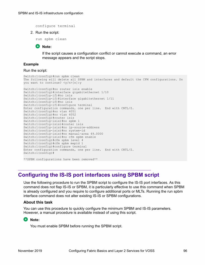
configure terminal2. Run the script:
run spbm clean
Note:
If the script causes a configuration conflict or cannot execute a command, an errormessage appears and the script stops.
ExampleRun the script:Switch:1(config)#run spbm clean The following will delete all SPBM and interfaces and default the CFM configurations. Do you want to continue? <y/n>[n]:y
Switch:1(config)#no router isis enableSwitch:1(config)#interface gigabitethernet 1/10Switch:1(config-if)#no isisSwitch:1(config-if)#interface gigabitethernet 1/11Switch:1(config-if)#no isisSwitch:1(config-if)#configure terminalEnter configuration commands, one per line. End with CNTL/Z.Switch:1(config)#no vlan 4051Switch:1(config)#no vlan 4052Switch:1(config)#router isisSwitch:1(config-isis)#no spbm 1Switch:1(config-isis)#router isisSwitch:1(config-isis)#no ip-source-addressSwitch:1(config-isis)#no system-idSwitch:1(config-isis)#no manual-area 49.0000Switch:1(config-isis)#no cfm spbm enableSwitch:1(config)#cfm spbm level 4Switch:1(config)#cfm spbm mepid 1Switch:1(config)#configure terminalEnter configuration commands, one per line. End with CNTL/Z.Switch:1(config)#
**SPBM configurations have been removed**
Configuring the IS-IS port interfaces using SPBM scriptUse the following procedure to run the SPBM script to configure the IS-IS port interfaces. As thiscommand does not flap IS-IS or SPBM, it is particularly effective to use this command when SPBMis already configured and you require to configure additional ports or MLTs. Running the run spbminterface command does not alter existing IS-IS or SPBM configurations.
About this taskYou can use this procedure to quickly configure the minimum SPBM and IS-IS parameters.However, a manual procedure is available instead of using this script.
Note:You must enable SPBM before running the SPBM script.
SPBM and IS-IS infrastructure configuration
November 2019 Configuring Fabric Basics and Layer 2 Services for VOSS 96
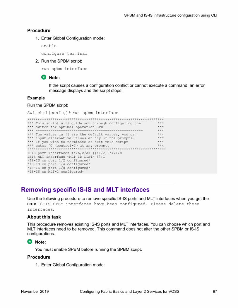
Procedure1. Enter Global Configuration mode:
enableconfigure terminal
2. Run the SPBM script:
run spbm interface
Note:
If the script causes a configuration conflict or cannot execute a command, an errormessage displays and the script stops.
ExampleRun the SPBM script:Switch:1(config)# run spbm interface******************************************************************** This script will guide you through configuring the ****** switch for optimal operation SPB. ****** --------------------------------------------------- ****** The values in [] are the default values, you can ****** input alternative values at any of the prompts. ****** If you wish to terminate or exit this script ****** enter ^C <control-C> at any prompt. *********************************************************************ISIS port interfaces <a/b,c/d> []:1/2,1/4,1/8ISIS MLT interface <MLT ID LIST> []:1*IS-IS on port 1/2 configured**IS-IS on port 1/4 configured**IS-IS on port 1/8 configured**IS-IS on MLT-1 configured*
Removing specific IS-IS and MLT interfacesUse the following procedure to remove specific IS-IS ports and MLT interfaces when you get theerror IS-IS SPBM interfaces have been configured. Please delete theseinterfaces.
About this taskThis procedure removes existing IS-IS ports and MLT interfaces. You can choose which port andMLT interfaces need to be removed. This command does not alter the other SPBM or IS-ISconfigurations.
Note:You must enable SPBM before running the SPBM script.
Procedure1. Enter Global Configuration mode:
SPBM and IS-IS infrastructure configuration using CLI
November 2019 Configuring Fabric Basics and Layer 2 Services for VOSS 97

enableconfigure terminal
2. Run the script:
run spbm interface clean
Note:
If the script causes a configuration conflict or cannot execute a command, an errormessage displays and the script stops.
ExampleRun the spbm interface clean script:Switch:1(config)# run spbm interface clean******************************************************************** This script will guide you through deleting the ****** IS-IS SPBM interfaces. ****** --------------------------------------------------- ****** The values in [] are the default values. ****** If you wish to terminate or exit this script ****** enter ^C <control-C> at any prompt. *********************************************************************ISIS port interfaces to be deleted <a/b,c/d>[]:1/2,1/4,1/8ISIS MLT interface <MLT ID LIST> []:1IS-IS port 1/2 deletedIS-IS port 1/4 deletedIS-IS port 1/8 deleted** 3 IS-IS port interfaces deleted **MLT 1 deleted** 1 IS-IS MLTs deleted **
Configuring minimum SPBM and IS-IS parametersUse the following procedure to configure the minimum required SPBM and IS-IS parameters toallow SPBM to operate on the switch.
Procedure1. Enter Global Configuration mode:
enableconfigure terminal
2. Enable SPBM globally:
spbm3. Enter IS-IS Router Configuration mode:
router isis4. Create the SPBM instance (only one SPBM instance is supported):
SPBM and IS-IS infrastructure configuration
November 2019 Configuring Fabric Basics and Layer 2 Services for VOSS 98

spbm <1–100>5. Add the SPBM B-VLAN to the SPBM instance:
spbm <1–100> b-vid {<vlan-id [-vlan-id][,...]} [primary <1-4059>]6. Configure the system nickname (2.5 bytes in the format <x.xx.xx>):
spbm <1–100> nick-name <x.xx.xx>
Note:
Although it is not strictly required for SPBM operation, you should change the IS-ISsystem ID from the default B-MAC value to a recognizable address to easily identify aswitch (Log on to IS-IS Router configuration mode and use the system-id<xxxx.xxxx.xxxx> command). This helps to recognize source and destinationaddresses for troubleshooting purposes.
7. Configure an IS-IS manual area (1-13 bytes in the format <xx.xxxx.xxxx...xxxx>. Only onemanual area is supported.):
manual-area <xx.xxxx.xxxx...xxxx>8. Exit IS-IS Router Configuration mode to Global Configuration mode:
exit9. Create the SPBM backbone VLAN (B-VLAN):
vlan create <2-4059> type spbm-bvlan10. Enter Interface Configuration mode, by specifying the ports or MLTs that are going to link to
the SPBM network:
interface {GigabitEthernet {slot/port[/sub-port][-slot/port[/sub-port]][,...]}| mlt <1–512> }
11. Configure an IS-IS interface on the selected ports or MLTs:
a. Create an IS-IS circuit and interface on the selected ports or MLTs:
isisb. Enable the SPBM instance on the IS-IS interfaces:
isis spbm <1–100>c. Enable the IS-IS circuit/interface on the selected ports or MLTs:
isis enable12. Enable interface.
13. Exit Interface Configuration mode:
exit14. Enable IS-IS globally:
router isis enable
SPBM and IS-IS infrastructure configuration using CLI
November 2019 Configuring Fabric Basics and Layer 2 Services for VOSS 99

15. Display the SPBM configurations:
show isis spbm16. Display the global IS-IS configuration:
show isis17. Display the interface IS-IS configuration:
show isis interfaceExampleSwitch> enableSwitch# configure terminalSwitch(config)# spbmSwitch(config)# router isisSwitch(config-isis)# spbm 1Switch(config-isis)# spbm 1 b–vid 4051,4052 primary 10Switch(config-isis)# spbm 1 nick-name 1.11.16Switch(config-isis)# manual-area c0.2000.000.00Switch(config-isis)# exitSwitch(config)# interface GigabitEthernet 1/21Switch(config-if)# isisSwitch(config-if)# isis spbm 1Switch(config-if)# isis enableSwitch(config-if)# exitSwitch(config)# vlan create 4051 type spbm-vlanSwitch(config)# vlan create 4052 type spbm-vlanSwitch(config)# router isis enableSwitch(config)# show isis spbmSwitch:1(config)#show isis spbm============================================================================================================== ISIS SPBM Info==============================================================================================================SPBM B-VID PRIMARY NICK LSDB IP IPV6 MULTICAST SPB-PIM-GW STP-MULTI INSTANCE VLAN NAME TRAP HOMING --------------------------------------------------------------------------------------------------------------1 4051-4052 4051 disable disable disable enable disable enable
============================================================================================================== ISIS SPBM SMLT Info==============================================================================================================SPBM SMLT-SPLIT-BEB SMLT-VIRTUAL-BMAC SMLT-PEER-SYSTEM-IDINSTANCE --------------------------------------------------------------------------------------------------------------1 primary 00:00:00:00:00:00
--------------------------------------------------------------------------------
SPBM and IS-IS infrastructure configuration
November 2019 Configuring Fabric Basics and Layer 2 Services for VOSS 100

Total Num of SPBM instances: 1--------------------------------------------------------------------------------
Switch(config)# show isis
================================================================================ ISIS General Info================================================================================ AdminState : enabled RouterType : Level 1 System ID : 0014.c7e1.33df Max LSP Gen Interval : 900 Metric : wide Overload-on-startup : 20 Overload : false Csnp Interval : 10 PSNP Interval : 2 Rxmt LSP Interval : 5 spf-delay : 100 Router Name : Switch1 ip source-address : 41.41.41.100 ipv6 source-address : 41:0:0:0:0:0:0:100 ip tunnel source-address : 11.11.12.11 Tunnel vrf : spboip ONA Port : 1/15 ip tunnel mtu : 1950 Num of Interfaces : 2 Num of Area Addresses : 1 inband-mgmt-ip : backbone : disabled Dynamically Learned Area : 00.0000.0000 FAN Member : No
Note:The ONA Port : 1/15 parameter in the preceding example is applicable only to the VirtualServices Platform 4000 Series.
Switch(config)# show isis interfaceSwitch# show isis interface================================================================================ ISIS Interfaces================================================================================IFIDX TYPE LEVEL OP-STATE ADM-STATE ADJ UP-ADJ SPBM-L1-METRIC--------------------------------------------------------------------------------Mlt2 pt-pt Level 1 UP UP 1 1 10Port1/21 pt-pt Level 1 UP UP 1 1 10
Variable definitionsUse the data in the following table to use the isis command.
Variable Valueenable Enables or disables the IS-IS circuit/interface on the
specified port or MLT.
The default is disabled. Use the no option to disableIS-IS on the specified interface.
spbm <1–100> Enable the SPBM instance on the IS-IS interfaces.
SPBM and IS-IS infrastructure configuration using CLI
November 2019 Configuring Fabric Basics and Layer 2 Services for VOSS 101
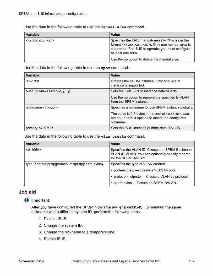
Use the data in the following table to use the manual-area command.
Variable Value<xx.xxx.xxx...xxx> Specifies the IS-IS manual-area (1–13 bytes in the
format <xx.xxx.xxx...xxx>). Only one manual area issupported. For IS-IS to operate, you must configureat least one area.
Use the no option to delete the manual area.
Use the data in the following table to use the spbm command.
Variable Value<1–100> Creates the SPBM instance. Only one SPBM
instance is supported.b-vid {<vlan-id [-vlan-id] [,...]} Sets the IS-IS SPBM instance data VLANs.
Use the no option to remove the specified B-VLANfrom the SPBM instance.
nick-name <x.xx.xx> Specifies a nickname for the SPBM instance globally.
The value is 2.5 bytes in the format <x.xx.xx>. Usethe no or default options to delete the configurednickname.
primary <1-4059> Sets the IS-IS instance primary data B-VLAN.
Use the data in the following table to use the vlan create command.
Variable Value<2-4059> Specifies the VLAN ID. Creates an SPBM Backbone
VLAN (B-VLAN). You can optionally specify a namefor the SPBM B-VLAN.
type {port-mstprstp|protocol-mstprstp|spbm-bvlan} Specifies the type of VLAN created.
• port-mstprstp — Create a VLAN by port.
• protocol-mstprstp — Create a VLAN by protocol.
• spbm-bvlan — Create an SPBM-BVLAN.
Job aidImportant:
After you have configured the SPBM nickname and enabled IS-IS. To maintain the samenickname with a different system ID, perform the following steps:
1. Disable IS-IS.
2. Change the system ID.
3. Change the nickname to a temporary one.
4. Enable IS-IS.
SPBM and IS-IS infrastructure configuration
November 2019 Configuring Fabric Basics and Layer 2 Services for VOSS 102
5. Wait up to 20 minutes for the LSPs with the original system ID to age out.
Note:
To check the age out time, use the show isis lsdb sysid <original-sys-id> command on any of the other SPB nodes in the network. When there is nooutput from this command, proceed to the next step. The time left (in seconds) forthe LSPs to age out is shown under the column LIFETIME.
6. Disable IS-IS.
7. Change the nickname to the original nickname.
8. Enable IS-IS.
Configuring minimum SPBM and IS-IS parameters using auto-nnicommand
Use the following procedure to configure the minimum required SPBM and IS-IS parameters usingthe auto-nni command to have the node create an IS-IS interface, attach the interface to anSPBM instance, and then enable IS-IS on the port interface.
This procedure is only for the port interface. The auto-nni command is not supported on the MLTinterface and the Fabric Extend Logical Interface.
About this taskThe auto-nni command provides a quick and simple way to configure the IS-IS interface. Youcan use the auto-nni command instead of the following existing IS-IS commands on the physical(port) interface:
• isis• isis spbm instance• isis enable
The existing commands are still available and you have the option to use the new command or thethree existing commands. If you need to modify any of the default parameters under isis or isisspbm instance , use isis and isis spbm instance constructs even if you created theinterface with the auto-nni command.
Procedure1. Enter Global Configuration mode:
enableconfigure terminal
2. Enable SPBM globally:
spbm
SPBM and IS-IS infrastructure configuration using CLI
November 2019 Configuring Fabric Basics and Layer 2 Services for VOSS 103

3. Enter IS-IS Router Configuration mode:
router isis4. Create the SPBM instance (only one SPBM instance is supported):
spbm <1–100>5. Add the SPBM B-VLAN to the SPBM instance:
spbm <1–100> b-vid {<vlan-id [-vlan-id][,...]} [primary <1-4059>]6. Configure the system nickname (2.5 bytes in the format <x.xx.xx>):
spbm <1–100> nick-name <x.xx.xx>
Note:
Although it is not strictly required for SPBM operation, you should change the IS-ISsystem ID from the default B-MAC value to a recognizable address to easily identify aswitch (Log on to IS-IS Router configuration mode and use the system-id<xxxx.xxxx.xxxx> command). This helps to recognize source and destinationaddresses for troubleshooting purposes.
7. Configure an IS-IS manual area (1-13 bytes in the format <xx.xxxx.xxxx...xxxx>. Only onemanual area is supported.):
manual-area <xx.xxxx.xxxx...xxxx>8. Exit IS-IS Router Configuration mode to Global Configuration mode:
exit9. Create the SPBM backbone VLAN (B-VLAN):
vlan create <2-4059> type spbm-bvlan10. Enter Interface Configuration mode, by specifying the ports or MLTs that are going to link to
the SPBM network:
interface {GigabitEthernet {slot/port[/sub-port][-slot/port[/sub-port]][,...]}| mlt <1–512> }
11. Configure an IS-IS interface on the selected ports.
auto-nni12. Enable interface.
13. Exit Interface Configuration mode:
exit14. Enable IS-IS globally:
router isis enable15. Display the SPBM configurations:
show isis spbm
SPBM and IS-IS infrastructure configuration
November 2019 Configuring Fabric Basics and Layer 2 Services for VOSS 104

16. Display the global IS-IS configuration:
show isis17. Display the interface IS-IS configuration:
show isis interfaceExampleSwitch> enableSwitch# configure terminalSwitch(config)# spbmSwitch(config)# router isisSwitch(config-isis)# spbm 1Switch(config-isis)# spbm 1 b–vid 10,20 primary 10Switch(config-isis)# spbm 1 nick-name 1.11.16Switch(config-isis)# manual-area c0.2000.000.00Switch(config-isis)# exitSwitch(config)# interface GigabitEthernet 1/21Switch(config-if)# auto-nniSwitch(config-if)# exitSwitch(config)# vlan create 10 type spbm-vlanSwitch(config)# vlan create 20 type spbm-vlanSwitch(config)# router isis enableSwitch(config)# show isis spbmSwitch:1(config)#show isis spbm============================================================================================================== ISIS SPBM Info==============================================================================================================SPBM B-VID PRIMARY NICK LSDB IP IPV6 MULTICAST SPB-PIM-GW STP-MULTI INSTANCE VLAN NAME TRAP HOMING --------------------------------------------------------------------------------------------------------------1 4051-4052 4051 disable disable disable enable disable enable
============================================================================================================== ISIS SPBM SMLT Info==============================================================================================================SPBM SMLT-SPLIT-BEB SMLT-VIRTUAL-BMAC SMLT-PEER-SYSTEM-IDINSTANCE --------------------------------------------------------------------------------------------------------------1 primary 00:00:00:00:00:00
--------------------------------------------------------------------------------Total Num of SPBM instances: 1--------------------------------------------------------------------------------
Switch(config)# show isis
================================================================================ ISIS General Info================================================================================
SPBM and IS-IS infrastructure configuration using CLI
November 2019 Configuring Fabric Basics and Layer 2 Services for VOSS 105

AdminState : enabled RouterType : Level 1 System ID : 0014.c7e1.33df Max LSP Gen Interval : 900 Metric : wide Overload-on-startup : 20 Overload : false Csnp Interval : 10 PSNP Interval : 2 Rxmt LSP Interval : 5 spf-delay : 100 Router Name : Switch1 ip source-address : 41.41.41.100 ipv6 source-address : 41:0:0:0:0:0:0:100 ip tunnel source-address : 11.11.12.11 Tunnel vrf : spboip ONA Port : 1/15 ip tunnel mtu : 1950 Num of Interfaces : 2 Num of Area Addresses : 1 inband-mgmt-ip : backbone : disabled Dynamically Learned Area : 00.0000.0000 FAN Member : No
Note:The ONA Port : 1/15 parameter in the preceding example is applicable only to the VirtualServices Platform 4000 Series.
Switch(config)# show isis interfaceSwitch# show isis interface================================================================================ ISIS Interfaces================================================================================IFIDX TYPE LEVEL OP-STATE ADM-STATE ADJ UP-ADJ SPBM-L1-METRIC--------------------------------------------------------------------------------Mlt2 pt-pt Level 1 UP UP 1 1 10Port1/21 pt-pt Level 1 UP UP 1 1 10
Configuring I-SIDs for private VLANsBefore you begin
• A private VLAN must be created. For more information about creating private VLANs, see Configuring VLANs, Spanning Tree, and NLB for VOSS.
About this taskThere is one I-SID per private VLAN.
Procedure1. Enter Global Configuration mode:
enableconfigure terminal
SPBM and IS-IS infrastructure configuration
November 2019 Configuring Fabric Basics and Layer 2 Services for VOSS 106
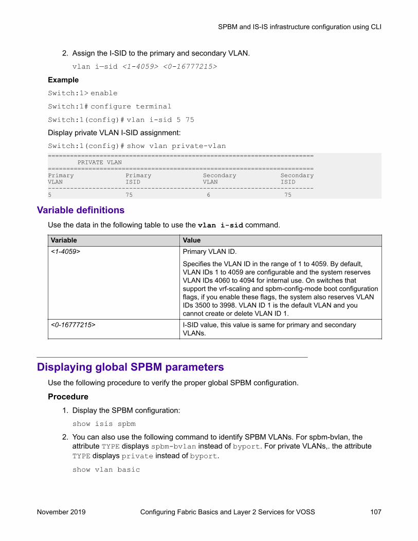
2. Assign the I-SID to the primary and secondary VLAN.
vlan i—sid <1-4059> <0-16777215>ExampleSwitch:1> enableSwitch:1# configure terminalSwitch:1(config)# vlan i-sid 5 75Display private VLAN I-SID assignment:Switch:1(config)# show vlan private-vlan======================================================================== PRIVATE VLAN ========================================================================Primary Primary Secondary SecondaryVLAN ISID VLAN ISID------------------------------------------------------------------------5 75 6 75
Variable definitionsUse the data in the following table to use the vlan i-sid command.
Variable Value<1-4059> Primary VLAN ID.
Specifies the VLAN ID in the range of 1 to 4059. By default,VLAN IDs 1 to 4059 are configurable and the system reservesVLAN IDs 4060 to 4094 for internal use. On switches thatsupport the vrf-scaling and spbm-config-mode boot configurationflags, if you enable these flags, the system also reserves VLANIDs 3500 to 3998. VLAN ID 1 is the default VLAN and youcannot create or delete VLAN ID 1.
<0-16777215> I-SID value, this value is same for primary and secondaryVLANs.
Displaying global SPBM parametersUse the following procedure to verify the proper global SPBM configuration.
Procedure1. Display the SPBM configuration:
show isis spbm2. You can also use the following command to identify SPBM VLANs. For spbm-bvlan, the
attribute TYPE displays spbm-bvlan instead of byport. For private VLANs,. the attributeTYPE displays private instead of byport.
show vlan basic
SPBM and IS-IS infrastructure configuration using CLI
November 2019 Configuring Fabric Basics and Layer 2 Services for VOSS 107
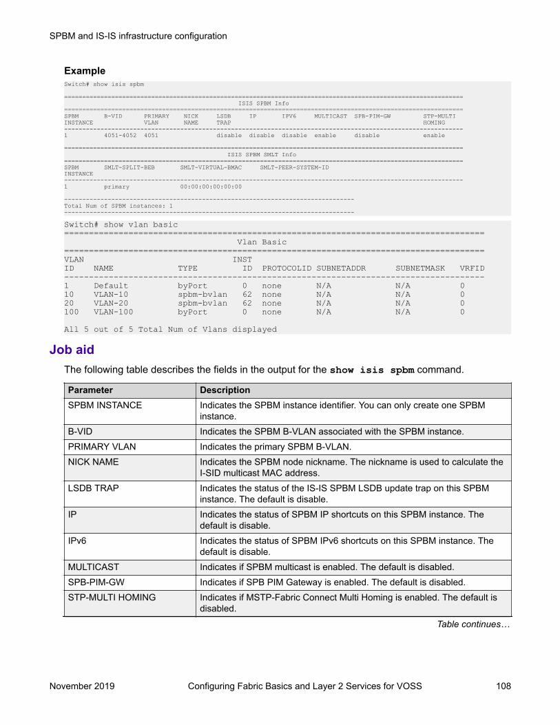
ExampleSwitch# show isis spbm
============================================================================================================== ISIS SPBM Info==============================================================================================================SPBM B-VID PRIMARY NICK LSDB IP IPV6 MULTICAST SPB-PIM-GW STP-MULTI INSTANCE VLAN NAME TRAP HOMING --------------------------------------------------------------------------------------------------------------1 4051-4052 4051 disable disable disable enable disable enable
============================================================================================================== ISIS SPBM SMLT Info==============================================================================================================SPBM SMLT-SPLIT-BEB SMLT-VIRTUAL-BMAC SMLT-PEER-SYSTEM-IDINSTANCE --------------------------------------------------------------------------------------------------------------1 primary 00:00:00:00:00:00
--------------------------------------------------------------------------------Total Num of SPBM instances: 1--------------------------------------------------------------------------------
Switch# show vlan basic===================================================================================== Vlan Basic=====================================================================================VLAN INSTID NAME TYPE ID PROTOCOLID SUBNETADDR SUBNETMASK VRFID-------------------------------------------------------------------------------------1 Default byPort 0 none N/A N/A 010 VLAN-10 spbm-bvlan 62 none N/A N/A 020 VLAN-20 spbm-bvlan 62 none N/A N/A 0100 VLAN-100 byPort 0 none N/A N/A 0
All 5 out of 5 Total Num of Vlans displayed
Job aidThe following table describes the fields in the output for the show isis spbm command.
Parameter DescriptionSPBM INSTANCE Indicates the SPBM instance identifier. You can only create one SPBM
instance.B-VID Indicates the SPBM B-VLAN associated with the SPBM instance.PRIMARY VLAN Indicates the primary SPBM B-VLAN.NICK NAME Indicates the SPBM node nickname. The nickname is used to calculate the
I-SID multicast MAC address.LSDB TRAP Indicates the status of the IS-IS SPBM LSDB update trap on this SPBM
instance. The default is disable.IP Indicates the status of SPBM IP shortcuts on this SPBM instance. The
default is disable.IPv6 Indicates the status of SPBM IPv6 shortcuts on this SPBM instance. The
default is disable.MULTICAST Indicates if SPBM multicast is enabled. The default is disabled.SPB-PIM-GW Indicates if SPB PIM Gateway is enabled. The default is disabled.STP-MULTI HOMING Indicates if MSTP-Fabric Connect Multi Homing is enabled. The default is
disabled.
Table continues…
SPBM and IS-IS infrastructure configuration
November 2019 Configuring Fabric Basics and Layer 2 Services for VOSS 108

Parameter DescriptionSMLT-SPLIT-BEB Specifies whether the switch is the primary or secondary vIST peer.SMLT-VIRTUAL-BMAC Specifies a virtual MAC address that can be used by both peers.SMLT-PEER-SYSTEM-ID Specifies the vIST peer system ID.
Displaying global IS-IS parametersUse the following procedure to display the global IS-IS parameters.
Procedure1. Display IS-IS configuration information:
show isis2. Display the IS-IS system-id:
show isis system-id3. Display IS-IS net info:
show isis netExample
Switch# show isis================================================================================ ISIS General Info================================================================================ AdminState : enabled RouterType : Level 1 System ID : 0014.c7e1.33df Max LSP Gen Interval : 900 Metric : wide Overload-on-startup : 20 Overload : false Csnp Interval : 10 PSNP Interval : 2 Rxmt LSP Interval : 5 spf-delay : 100 Router Name : Switch1 ip source-address : 192.0.2.0 ipv6 source-address : 41:0:0:0:0:0:0:100 ip tunnel source-address : 192.0.2.10 Tunnel vrf : spboip ONA Port : 1/15 ip tunnel mtu : 1950 Num of Interfaces : 2 Num of Area Addresses : 1 inband-mgmt-ip : backbone : disabled Dynamically Learned Area : 00.0000.0000 FAN Member : No
SPBM and IS-IS infrastructure configuration using CLI
November 2019 Configuring Fabric Basics and Layer 2 Services for VOSS 109
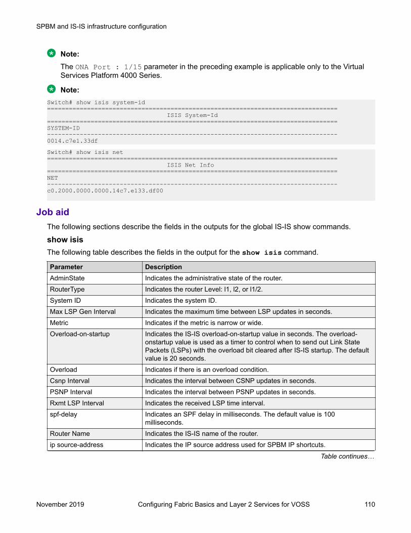
Note:The ONA Port : 1/15 parameter in the preceding example is applicable only to the VirtualServices Platform 4000 Series.
Note:Switch# show isis system-id================================================================================ ISIS System-Id================================================================================SYSTEM-ID --------------------------------------------------------------------------------0014.c7e1.33dfSwitch# show isis net================================================================================ ISIS Net Info================================================================================NET --------------------------------------------------------------------------------c0.2000.0000.0000.14c7.e133.df00
Job aidThe following sections describe the fields in the outputs for the global IS-IS show commands.
show isisThe following table describes the fields in the output for the show isis command.
Parameter DescriptionAdminState Indicates the administrative state of the router.RouterType Indicates the router Level: l1, l2, or l1/2.System ID Indicates the system ID.Max LSP Gen Interval Indicates the maximum time between LSP updates in seconds.Metric Indicates if the metric is narrow or wide.Overload-on-startup Indicates the IS-IS overload-on-startup value in seconds. The overload-
onstartup value is used as a timer to control when to send out Link StatePackets (LSPs) with the overload bit cleared after IS-IS startup. The defaultvalue is 20 seconds.
Overload Indicates if there is an overload condition.Csnp Interval Indicates the interval between CSNP updates in seconds.PSNP Interval Indicates the interval between PSNP updates in seconds.Rxmt LSP Interval Indicates the received LSP time interval.spf-delay Indicates an SPF delay in milliseconds. The default value is 100
milliseconds.Router Name Indicates the IS-IS name of the router.ip source-address Indicates the IP source address used for SPBM IP shortcuts.
Table continues…
SPBM and IS-IS infrastructure configuration
November 2019 Configuring Fabric Basics and Layer 2 Services for VOSS 110
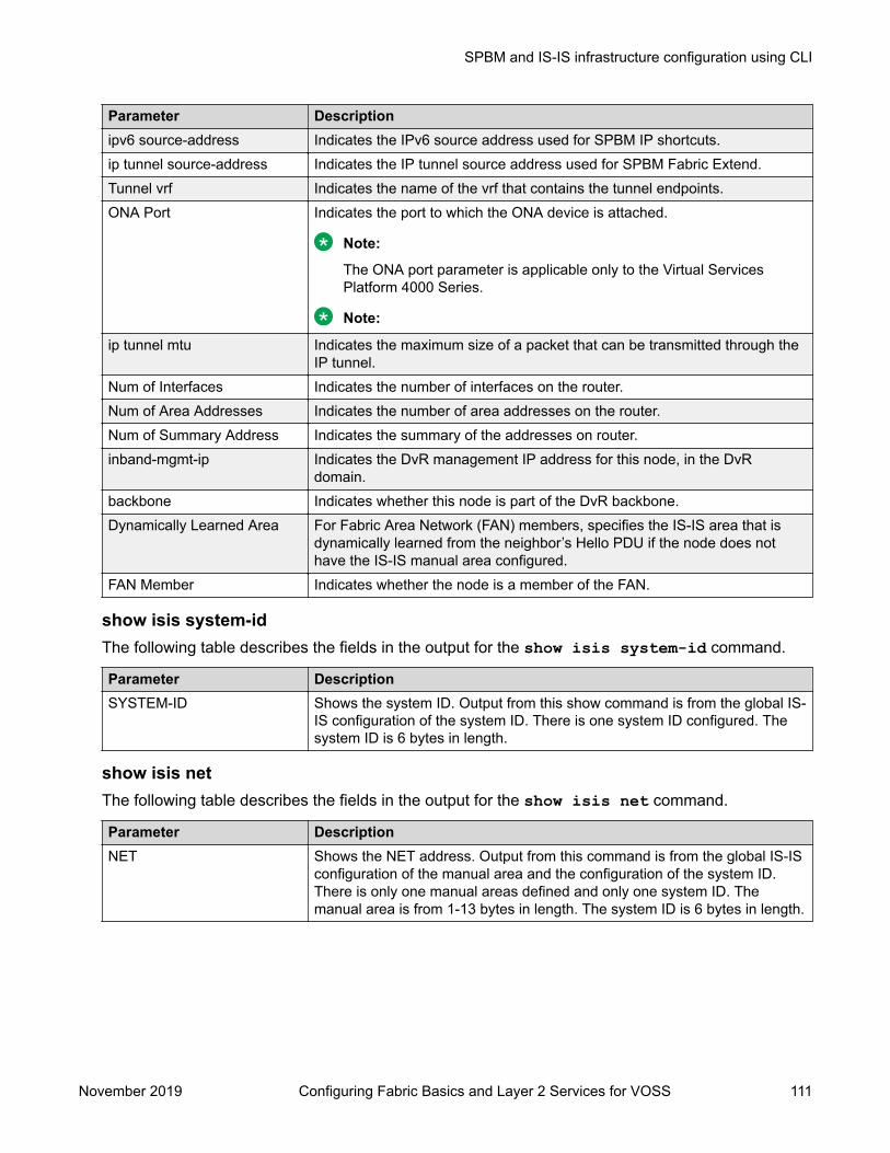
Parameter Descriptionipv6 source-address Indicates the IPv6 source address used for SPBM IP shortcuts.ip tunnel source-address Indicates the IP tunnel source address used for SPBM Fabric Extend.Tunnel vrf Indicates the name of the vrf that contains the tunnel endpoints.ONA Port Indicates the port to which the ONA device is attached.
Note:
The ONA port parameter is applicable only to the Virtual ServicesPlatform 4000 Series.
Note:
ip tunnel mtu Indicates the maximum size of a packet that can be transmitted through theIP tunnel.
Num of Interfaces Indicates the number of interfaces on the router.Num of Area Addresses Indicates the number of area addresses on the router.Num of Summary Address Indicates the summary of the addresses on router.inband-mgmt-ip Indicates the DvR management IP address for this node, in the DvR
domain.backbone Indicates whether this node is part of the DvR backbone.Dynamically Learned Area For Fabric Area Network (FAN) members, specifies the IS-IS area that is
dynamically learned from the neighbor’s Hello PDU if the node does nothave the IS-IS manual area configured.
FAN Member Indicates whether the node is a member of the FAN.
show isis system-idThe following table describes the fields in the output for the show isis system-id command.
Parameter DescriptionSYSTEM-ID Shows the system ID. Output from this show command is from the global IS-
IS configuration of the system ID. There is one system ID configured. Thesystem ID is 6 bytes in length.
show isis netThe following table describes the fields in the output for the show isis net command.
Parameter DescriptionNET Shows the NET address. Output from this command is from the global IS-IS
configuration of the manual area and the configuration of the system ID.There is only one manual areas defined and only one system ID. Themanual area is from 1-13 bytes in length. The system ID is 6 bytes in length.
SPBM and IS-IS infrastructure configuration using CLI
November 2019 Configuring Fabric Basics and Layer 2 Services for VOSS 111

Displaying IS-IS areasUse the following procedure to display IS-IS areas.
ProcedureUse the following procedure to display IS-IS areas.
show isis manual-areaExampleSwitch# show isis manual-area================================================================================ ISIS Manual Area Address================================================================================
AREA ADDRESS --------------------------------------------------------------------------------c0.2000.0000.00
Job aidThe following table describes the fields in the output for the show isis manual-area command.
Parameter DescriptionAREA ADDRESS Shows the manual areas defined. There can only be
one area. Use the same manual area across theentire SPBM cloud. The manual area can be from1-13 bytes in length.
Configuring SMLT parameters for SPBMUse the following procedure to configure the required Split MultiLink Trunking (SMLT) parameters toallow SPBM to interoperate with SMLT on the switch.
Note:• The assignment of primary and secondary roles to the vIST peers is automatic. The switch
with the lower system ID (between the two vIST peers) is primary, and the switch with thehigher system ID is secondary when default system-id values are being used.
• SMLT peer system ID is part of the required configuration. You must configure the SMLTpeer system ID as the nodal MAC of the peer device. In the IS-IS network, the nodal MACof devices should be eight apart from each other.
• When using the default hardware assigned system-id value, the SMLT Virtual BMAC isautomatically derived by comparing the system-id values of the two vIST peers. A value of0x01 plus the lower of the two system-id values is used as the SMLT Virtual BMAC.
SPBM and IS-IS infrastructure configuration
November 2019 Configuring Fabric Basics and Layer 2 Services for VOSS 112

When using a manually configured system-id value, the SMLT Virtual BMAC must also bemanually configured.
• An I-SID must be assigned to every VLAN that is a member of a Layer 2 VSN. Also, if aLayer 2 VSN is created on one vIST Peer, it must also be created on the other vIST peer.
Procedure1. Enter Global Configuration mode:
enableconfigure terminal
2. Disable IS-IS on the switch:
no router isis enable3. Enter IS-IS Router Configuration mode:
enableconfigure terminalrouter isis
4. Specify the system ID of the vIST peer, so that if it goes down, the local peer can take overforwarding for the failed peer:
spbm <1–100> smlt-peer—system—id <xxxx.xxxx.xxxx>5. Configure the virtual B-MAC, which is shared and advertised by both peers:
spbm <1–100> smlt-virtual-bmac <0x00:0x00:0x00:0x00:0x00:0x00>6. Exit to Global Configuration mode:
exit7. Enable IS-IS on the switch:
router isis enable8. Display the SPBM SMLT configuration:
show isis spbmExampleSwitch:1>enableSwitch:1#configure terminal
Disable IS-IS on the switch:Switch:1(config)#no router isis enable
Enter the IS-IS Router Configuration mode:Switch:1(config)#router isisSwitch:1(config-isis)#spbm 1 smlt-peer-system-id 0018.b0bb.b3df
SPBM and IS-IS infrastructure configuration using CLI
November 2019 Configuring Fabric Basics and Layer 2 Services for VOSS 113

Switch:1(config-isis)#spbm 1 smlt-virtual-bmac 00:14:c7:e1:33:e0Switch:1(config-isis)#router isis enableSwitch:1(config-isis)#show isis spbm============================================================================================================== ISIS SPBM Info==============================================================================================================SPBM B-VID PRIMARY NICK LSDB IP IPV6 MULTICAST SPB-PIM-GW STP-MULTI INSTANCE VLAN NAME TRAP HOMING --------------------------------------------------------------------------------------------------------------1 4051-4052 4051 disable disable disable enable disable enable
============================================================================================================== ISIS SPBM SMLT Info==============================================================================================================SPBM SMLT-SPLIT-BEB SMLT-VIRTUAL-BMAC SMLT-PEER-SYSTEM-IDINSTANCE --------------------------------------------------------------------------------------------------------------1 primary 00:00:00:00:00:00
--------------------------------------------------------------------------------Total Num of SPBM instances: 1--------------------------------------------------------------------------------
Variable definitionsUse the data in the following table to use the spbm command.
Variable Valuesmlt-peer-system-id <xxxx.xxxx.xxxx> Specifies the IS-IS SPBM peer system ID.
SMLT peer system ID is part of the required configuration. Youmust configure the SMLT peer system ID as the nodal MAC ofthe peer device. In the IS-IS network, the nodal MAC of devicesshould be eight apart from each other.
smlt-virtual-bmac<0x00:0x00:0x00:0x00:0x00:0x00>
Specifies a virtual MAC address that can be used by both peers.
SMLT virtual B-MAC is an optional configuration.
Note:
• If SMLT virtual B-MAC is not configured, the systemderives SMLT virtual B-MAC from the configured SMLTpeer system ID and the nodal MAC of the device (IS-ISsystem ID). The system compares the nodal MAC of thedevice with the SMLT peer system ID configured andtakes the small one, plus 0x01, as the SMLT virtual B-MAC.
• The system also derives SMLT split BEB from the SMLTpeer system ID and nodal MAC of the device. The devicewith the lower system ID is primary, the device with thehigher system ID is secondary.
Configuring optional SPBM parametersUse the following procedure to configure optional SPBM parameters.
SPBM and IS-IS infrastructure configuration
November 2019 Configuring Fabric Basics and Layer 2 Services for VOSS 114

Procedure1. Enter Global Configuration mode:
enableconfigure terminal
2. Configure the SPBM ethertype:
spbm ethertype {0x8100 | 0x88a8}3. Configure the optional link-state database (LSDB) trap global parameter. To configure this
parameter, you must globally disable IS-IS on the switch:
a. Disable IS-IS on the switch:
no router isis enableb. Enter IS-IS Router Configuration mode:
router isisc. Enable a trap when the SPBM LSDB changes:
spbm <1–100> lsdb-trap enabled. Enable IS-IS on the switch:
router isis enablee. Exit IS-IS Router Configuration mode:
exit4. Configure the optional SPBM interface parameters. To configure these parameters, you must
disable IS-IS on the interface:
a. Specify an SPBM interface to configure:
interface {GigabitEthernet {slot/port[/sub-port][-slot/port[/sub-port]][,...]} | mlt <mltid> }
b. Disable IS-IS on the interface:
no isis enablec. Configure SPBM instance interface-type on IS-IS interface. SPBM supports only pt-pt:
isis spbm <1–100> interface-type {broadcast|pt-pt}d. Configure the SPBM instance level 1 metric on the IS-IS interface:
isis spbm <1–100> l1-metric <1–16777215>e. Enable IS-IS on the switch:
isis enableExampleSwitch> enable
SPBM and IS-IS infrastructure configuration using CLI
November 2019 Configuring Fabric Basics and Layer 2 Services for VOSS 115

Switch# configure terminalSwitch(config)# spbm ethertype 0x8100Switch(config-isis)# no router isis enableSwitch(config)# router isisSwitch(config-isis)# spbm 1 lsdb-trap enableSwitch(config-isis)# router isis enableSwitch(config-isis)# exitSwitch(config)# interface gigabitethernet 1/7Switch(config-if)# no isis enableSwitch(config-if)# isis spbm 1 interface-type pt-ptSwitch(config-if)# isis spbm 1 l1–metric 500Switch(config-if)# isis enable
Variable definitionsUse the data in the following table to use the spbm command.
Variable Valueethertype {0x8100 | 0x88a8} Configures the SPBM ethertype. The default value is
0x8100.<1–100> lsdb-trap enable Configures whether to enable or disable a trap when
the SPBM LSDB changes.
The default is disabled. Use the no or default optionsto disable LSDB traps.
Use the data in the following table to use the isis spbm command.
Variable Value<1–100> interface-type {broadcast|pt-pt} Configures the SPBM instance interface-type on the
IS-IS interface located on the specified port or MLT.SPBM only supports the point-to-point (pt-pt)interface type.
The default is pt-pt. Use the no or default options toset this parameter to the default value of pt-pt.
<1–100> l1–metric <1–16777215> Configures the SPBM instance l1-metric on the IS-ISinterface located on the specified port or MLT. Thedefault value is 10.
Use the no or default options to set this parameter tothe default.
SPBM and IS-IS infrastructure configuration
November 2019 Configuring Fabric Basics and Layer 2 Services for VOSS 116

Configuring optional IS-IS global parametersUse the following procedure to configure optional IS-IS global parameters.
Procedure1. Enter IS-IS Router Configuration mode:
enableconfigure terminalrouter isis
2. Configure optional IS-IS global parameters:
a. Specify the Complete Sequence Number Packet (CSNP) interval in seconds:
csnp-interval <1–600>b. Configure the router type globally:
is-type {l1|l12}c. Configure the maximum level, in seconds, between generated LSPs by this
Intermediate System:
max-lsp-gen-interval <30–900>d. Configure the IS-IS metric type:
metric {narrow|wide}e. Set or clear the overload condition:
overloadf. Configure the overload-on-startup value in seconds:
overload-on-startup <15–3600>g. Configure the Partial Sequence Number Packet (PSNP) in seconds:
psnp-interval <1–120>h. Configure the minimum time between retransmission of an LSP:
retransmit-lsp-interval <1–300>i. Configure the SPF delay in milliseconds:
spf-delay <0–5000>j. Configure the name for the system:
sys-name WORD<0–255>k. Configure the IS-IS system ID for the switch:
system-id <xxxx.xxxx.xxxx>
SPBM and IS-IS infrastructure configuration using CLI
November 2019 Configuring Fabric Basics and Layer 2 Services for VOSS 117

ExampleSwitch> enableSwitch# configure terminalSwitch(config)# router isisSwitch(config-isis)# csnp-interval 10Switch(config-isis)# is-type l1Switch(config-isis)# max-lsp-gen-interval 800Switch(config-isis)# metric wideSwitch(config-isis)# overloadSwitch(config-isis)# overload-on-startup 30Switch(config-isis)# psnp-interval 10Switch(config-isis)# retransmit-lsp-interval 10Switch(config-isis)# default sys-nameSwitch(config-isis)# spf-delay 200Switch(config-isis)# default system-id
Variable definitionsUse the data in the following table to use the csnp-interval command.
Variable Value<1–600> Specifies the CSNP interval in seconds. This is a
system level parameter that applies for level 1 CSNPgeneration on all interfaces. A longer intervalreduces overhead, while a shorter interval speeds upconvergence.
The default value is 10. Use the no or default optionsto set this parameter to the default value of 10.
Use the data in the following table to configure the is-type command.
Variable Value{l1|l12} Sets the router type globally:
• l1: Level-1 router type
• l12: Not valid.
The default value is l1. Use the no or default optionsto set this parameter to the default value of l1.
Use the data in the following table to configure the max-lsp-gen-interval command.
SPBM and IS-IS infrastructure configuration
November 2019 Configuring Fabric Basics and Layer 2 Services for VOSS 118

Variable Value<30–900> Specifies the maximum interval, in seconds, between
generated LSPs by this Intermediate System.
The default value is 900 seconds. Use the no ordefault options to set this parameter to the defaultvalue of 900.
Use the data in the following table to configure the metric command.
Variable Value{narrow|wide} Specifies the IS-IS metric type. Only wide is
supported.
The default value is wide. Use the no or defaultoptions to set this parameter to the default value ofwide.
Use the data in the following table to configure the overload command.
Variable Valueoverload Sets or clears the overload condition.
The default value is disabled. Use the no or defaultoptions to set this parameter to the default value ofdisabled.
Use the data in the following table to configure the overload-on-startup command.
Variable Value<15–3600> Specifies the IS-IS overload-on-startup value in
seconds. The overload-on-startup value is used as atimer to control when to send out LSPs with theoverload bit cleared after IS-IS startup.
The default value is 20. Use the no or default optionsto set this parameter to the default value of 20.
Use the data in the following table to configure the psnp-interval command.
Variable Value<1–120> Specifies the PSNP interval in seconds. This is a
system level parameter that applies for level 1 PSNPgeneration on all interfaces. A longer intervalreduces overhead, while a shorter interval speeds upconvergence.
The default value is 2. Use the no or default optionsto set this parameter to the default value of 2.
Use the data in the following table to configure the retransmit-lsp-interval command.
SPBM and IS-IS infrastructure configuration using CLI
November 2019 Configuring Fabric Basics and Layer 2 Services for VOSS 119

Variable Value<1–300> Specifies the minimum time between retransmission
of an LSP. This defines how fast the switch resendsthe same LSP. This is a system level parameter thatapplies for Level1 retransmission of LSPs.
The default value is 5 seconds. Use the no or defaultoptions to set this parameter to the default value of5.
Use the data in the following table to configure the spf-delay command.
Variable Value<0–5000> Configures the delay, in milliseconds, to pace
successive Shortest Path First (SPF) runs. The timerprevents more than two SPF runs from beingscheduled back-to-back. The mechanism for pacingSPF allows two back-to-back SPF runs.
The default value is 100 milliseconds. Use the no ordefault options to set this parameter to the defaultvalue of 100 milliseconds.
Use the data in the following table to configure the sys-name command.
Variable ValueWORD<0–255> Specifies a name for the system. This may be used
as the host name for dynamic host name exchangein accordance with RFC 2763.
By default, the system name comes from the hostname configured at the system level.
Use the no or default options to set this parameter tothe default value (host name).
Note:
No consistency checks appear when you editsys-name.
Use the data in the following table to configure the system-id command.
Variable Value<xxxx.xxxx.xxxx> Specifies the IS-IS system ID for the switch.
Use the no or default options to set this parameter tothe default value (node BMAC).
SPBM and IS-IS infrastructure configuration
November 2019 Configuring Fabric Basics and Layer 2 Services for VOSS 120

Job aidImportant:
After you have configured the SPBM nickname and enabled IS-IS. To maintain the samenickname with a different system ID, perform the following steps:
1. Disable IS-IS.
2. Change the system ID.
3. Change the nickname to a temporary one.
4. Enable IS-IS.
5. Wait up to 20 minutes for the LSPs with the original system ID to age out.
Note:
To check the age out time, use the show isis lsdb sysid <original-sys-id> command on any of the other SPB nodes in the network. When there is nooutput from this command, proceed to the next step. The time left (in seconds) forthe LSPs to age out is shown under the column LIFETIME.
6. Disable IS-IS.
7. Change the nickname to the original nickname.
8. Enable IS-IS.
Configuring optional IS-IS interface parametersUse the following procedure to configure optional IS-IS interface parameters.
Important:
Save your configuration using save config for the updates to be available after reboot.Saving the configuration also ensures that any authentication keys (passwords) specified duringthe configuration are properly encrypted.
Procedure1. Enter Interface Configuration mode:
enableconfigure terminalinterface GigabitEthernet {slot/port[/sub-port][-slot/port[/sub-port]][,...]} or interface mlt <1-512>
Note:
If your platform supports channelization and the port is channelized, you must alsospecify the sub-port in the format slot/port/sub-port.
SPBM and IS-IS infrastructure configuration using CLI
November 2019 Configuring Fabric Basics and Layer 2 Services for VOSS 121

2. Configure optional IS-IS interface parameters:
a. Specify the authentication type used for IS-IS hello packets on the interface:
isis hello-auth type {none|simple|hmac-md5|hmac-sha-256}b. If you select simple as the hello-auth type, you must also specify a key value but
the key-id is optional:
isis hello-auth type simple key WORD<1–16> [key-id <1–255>]c. If you select hmac-md5 or hmac-sha-256, you must also specify a key value. The
key-id is optional:
isis hello-auth type hmac-md5 key WORD<1–16> [key-id <1–255>]]isis hello-auth type hmac-sha-256 key WORD<1–16> [key-id <1–255>]]
d. Configure the level 1 IS-IS designated router priority:
isis [l1-dr-priority <0–127>]
Note:
This parameter is not used for SPBM because SPBM only runs on point-to-pointinterfaces. This parameter is for designated router election on a broadcast LANsegment, which is not supported.
e. Configure the level 1 hello interval:
isis [l1-hello-interval <1–600>]f. Configure the level 1 hello multiplier:
isis [l1-hello-multiplier <1–600>]ExampleSwitch:1> enableSwitch:1# configure terminalSwitch(config):1# interface gigabitethernet 1/1Switch(config-if):1# isisSwitch(config-if):1# isis hello-auth type hmac-md5 key testSwitch(config-if):1# isis l1–dr-priority 100Switch(config-if):1# isis l1–hello-interval 20Switch(config-if):1# isis l1–hello-multiplier 10Switch(config):1# save config
Variable definitionsUse the data in the following table to configure the isis command.
SPBM and IS-IS infrastructure configuration
November 2019 Configuring Fabric Basics and Layer 2 Services for VOSS 122

Variable Valuehello-auth type {none|simple|hmac-md5|hmac-sha-256}][key [key WORD<1–16> ][key-id <1–255> ]
Specifies the authentication type used for IS-IS hello packets onthe interface. type can be one of the following:
• none
• simple: If selected, you must also specify a key value but thekey id is optional. Simple password authentication uses a textpassword in the transmitted packet. The receiving router usesan authentication key (password) to verify the packet.
• hmac-md5: If selected, you must also specify a key value butthe key-id is optional. MD5 authentication creates an encodedchecksum in the transmitted packet. The receiving router usesan authentication key (password) to verify the MD5 checksumof the packet. There is an optional key ID.
• hmac-sha–256: If selected, you must also specify a key valuebut the key-id is optional. With SHA-256 authentication, theswitch adds an hmac-sha–256 digest to each Hello packet.The switch that receives the Hello packet computes the digestof the packet and compares it with the received digest. If thedigests match, the packet is accepted. If the digests do notmatch, the receiving switch discards the packet. There is anoptional key ID.
Note:
Secure Hashing Algorithm 256 bits (SHA-256) is a cipherand a cryptographic hash function of SHA2authentication. You can use SHA-256 to authenticate IS-IS Hello messages. This authentication method uses theSHA-256 hash function and a secret key to establish asecure connection between switches that share the samekey.
This feature is in full compliance with RFC 5310.
The default is none. Use the no or default options to set thehello-auth type to none.
l1-dr-priority <0–127> Configures the level 1 IS-IS designated router priority to thespecified value. The default value is 64.
Use the no or default options to set this parameter to the defaultvalue of 64.
Note:
This parameter is not used for SPBM because SPBM onlyruns on point-to-point interfaces. This parameter is fordesignated router election on a broadcast LAN segment,which is not supported.
Table continues…
SPBM and IS-IS infrastructure configuration using CLI
November 2019 Configuring Fabric Basics and Layer 2 Services for VOSS 123

Variable Valuel1-hello-interval <1–600> Configures the level 1 hello interval. The default value is 9
seconds.
Use the no or default options to set this parameter to the defaultvalue of 9 seconds.
l1-hello-multiplier <1–600> Configures the level 1 hello multiplier. The default value is 3seconds.
Use the no or default options to set this parameter to the defaultvalue of 3 seconds.
Displaying IS-IS interface parametersUse the following procedure to display the IS-IS interface parameters.
Procedure1. Enter Privileged EXEC mode:
enable2. Display IS-IS interface configuration and status parameters (including adjacencies):
show isis interface [l1|l2|l12]3. Display IS-IS interface authentication configuration:
show isis int-auth4. Display IS-IS interface timers:
show isis int-timers5. Display IS-IS circuit level parameters:
show isis int-ckt-levelExampleSwitch:1# show isis interface================================================================================ ISIS Interfaces================================================================================IFIDX TYPE LEVEL OP-STATE ADM-STATE ADJ UP-ADJ SPBM-L1-METRIC--------------------------------------------------------------------------------Mlt2 pt-pt Level 1 UP UP 1 1 10Port1/21 pt-pt Level 1 UP UP 1 1 10Switch:1# show isis int-auth================================================================================ ISIS Interface Auth================================================================================IFIDX AUTH-TYPE AUTH-KEYID AUTH-KEY --------------------------------------------------------------------------------
SPBM and IS-IS infrastructure configuration
November 2019 Configuring Fabric Basics and Layer 2 Services for VOSS 124

Mlt2 none 0 Port1/21 none 0 Switch:1# show isis int-timers================================================================================ ISIS Interface Timers================================================================================IFIDX LEVEL HELLO HELLO HELLO INTERVAL MULTIPLIER DR --------------------------------------------------------------------------------Mlt2 Level 1 9 3 3 Port1/21 Level 1 9 3 3
Switch:1# show isis int-ckt-level================================================================================ ISIS Circuit level parameters================================================================================IFIDX LEVEL DIS CKTID --------------------------------------------------------------------------------Mlt2 Level 1 1 Port1/21 Level 1 2
Variable definitionsUse the data in the following table to use the IS-IS interface show command.
Variable Value[l1, l2, l12] Displays the interface information for the specified level: l1, l2, or
l12.
Job aidThe following sections describe the fields in the outputs for the IS-IS interface show commands.
show isis interfaceThe following table describes the fields in the output for the show isis interface command.
Parameter DescriptionIFIDX Indicates the interface index for the Ethernet or MLT interface.TYPE Indicates the type of interface configured (only pt-pt is supported).LEVEL Indicates the level of the IS-IS interface (Level 1 [default] or Level 2).OP-STATE Shows the physical connection state of the interface.ADM-STATE Shows the configured state of the interface.ADJ Shows how many adjacencies are learned through the interface.UP-ADJ Shows how many adjacencies are active through the interface.SPBM-L1–METRIC Indicates the SPBM instance Level 1 metric on the IS-IS interface.
show isis int-authThe following table describes the fields in the output for the show isis int-auth command.
SPBM and IS-IS infrastructure configuration using CLI
November 2019 Configuring Fabric Basics and Layer 2 Services for VOSS 125

Parameter DescriptionIFIDX Shows the interface index for the Ethernet or MLT interface.AUTH-TYPE Shows the type of authentication configured for the interface. Types include:
• none for no authentication.
• simple for a simple password.
• hmac-md5 for MD5 encryption.
• hmac-sha–256 for SHA-256 encryption.AUTH-KEYID Shows the authentication password configured for the interface.
If the KeyId is not configured, the value is 0.AUTH-KEY Shows the HMAC-MD5 key needed for encryption. This is used only for
HMAC-MD5.
show isis int-timersThe following table describes the fields in the output for the show isis int-timers command.
Parameter DescriptionIFIDX Indicates the interface index for the Ethernet or MLT interface.LEVEL Indicates the IS-IS interface level.HELLO INTERVAL Indicates the interval at which a Hello packet is sent to the IS-IS network.HELLO MULTIPLIER Indicates the multiplier that is used in conjunction with the Hello Interval.HELLO DR Indicates the interval at which a Hello packet is sent to the IS-IS network if
the router is a designated router (DIS).
show isis int-ckt-levelThe following table describes the fields in the output for the show isis int-ckt-levelcommand.
Parameter DescriptionIFIDX Shows the interface index for the ethernet or MLT interface.LEVEL Shows the level of the IS-IS interface (Level 1 [default] or Level 2).DIS Shows the Designated Intermediate System (DIS) of the circuit.CKT ID Displays the CKT ID.
Displaying the IP unicast FIB, multicast FIB, unicast FIB, andunicast tree
Use the following procedure to display SPBM IP unicast Forwarding Information Base (FIB), SPBMmulticast FIB, unicast FIB, and the unicast tree.
SPBM and IS-IS infrastructure configuration
November 2019 Configuring Fabric Basics and Layer 2 Services for VOSS 126

In SPBM, Backbone MAC (B-MAC) addresses are carried within the IS-IS link-state database. To dothis, SPBM supports an IS-IS Type-Length-Value (TLV) that advertises the Service InstanceIdentifier (I-SID) and B-MAC information across the network. Each node has a System ID, whichalso serves as B-MAC of the switch. These B-MAC addresses are populated into the SPBMForwarding Information Base (FIB).
When the network topology is discovered and stored in the IS-IS link-state database, each nodecalculates shortest path trees for each source node, so that a unicast path now exists from everynode to every other node. With this information, each node populates unicast information receivedfrom SPBM into the FIB for forwarding purposes.
I-SIDs are only used for virtual services (Layer 2 VSNs and Layer 3 VSNs). If you only enable IPShortcuts on the Backbone Edge Bridges, I-SIDs are never exchanged in the network as IPShortcuts allow Global Routing Table (GRT) IP networks to be transported across IS-IS.
The show isis spbm ip-unicast-fib or show isis spbm ipv6-unicast-fib commanddisplays all of the IS-IS routes in the IS-IS LSDB. The IP ROUTE PREFERENCE column in theshow output displays the IP route preference.
Routes within the same VSN are added to the LSDB with a default preference of 7. Inter-VSN routesare added to the LSDB with a route preference of 200. IS-IS accept policies allow you to change theroute preference for incoming routes. If the same route is learned from multiple sources withdifferent route preferences, then the routes are not considered equal cost multipath (ECMP) routes.The route with the lowest route preference is the preferred route. In Layer 2, in the event of a tie-break between routes from multiple sources, the tie-breaking is based on cost and hop count.
Procedure1. Enter Privileged EXEC mode:
enable2. Display the SPBM IP unicast FIB:
• For IPv4:
show isis spbm ip-unicast-fib [all] [id <1–16777215] [spbm-nh-as-mac]
• For IPv6:
show isis spbm ipv6-unicast-fib [all] [id <1–16777215] [spbm-nh-as-mac]
3. Display the SPBM multicast FIB:
show isis spbm multicast-fib [vlan <1-4059>] [i-sid <1–16777215>][nick-name <x.xx.xx>] [summary]
4. Display the SPBM unicast FIB:
show isis spbm unicast-fib [b-mac <0x00:0x00:0x00:0x00:0x00:0x00>][vlan <1-4059>] [summary]
5. Display the SPBM unicast tree:
SPBM and IS-IS infrastructure configuration using CLI
November 2019 Configuring Fabric Basics and Layer 2 Services for VOSS 127

show isis spbm unicast-tree <1-4059> [destination <xxxx.xxxx.xxxx>]ExampleSwitch# show isis spbm ip-unicast-fib ========================================================================================== SPBM IP-UNICAST FIB ENTRY INFO========================================================================================== VRF DEST OUTGOING SPBM PREFIX PREFIX IP ROUTEVRF ISID ISID Destination NH BEB VLAN INTERFACE COST COST TYPE PREFERENCE------------------------------------------------------------------------------------------GRT - - 10.133.136.0/24 4K3(*) 4058 1/3 10 1 Internal 7GRT - - 10.133.136.0/24 4K3(*) 4059 1/3 10 1 Internal 7GRT - - 10.133.136.0/24 4K4(*) 4058 to_4k4 10000 1 Internal 7GRT - - 10.133.136.0/24 4K4(*) 4059 to_4k4 10000 1 Internal 7------------------------------------------------------------------------------------------ Total number of SPBM IP-UNICAST FIB entries 4------------------------------------------------------------------------------------------Switch# show isis spbm ip-unicast-fib id 10002 ========================================================================================== SPBM IP-UNICAST FIB ENTRY INFO========================================================================================== VRF DEST OUTGOING SPBM PREFIX PREFIX IP ROUTEVRF ISID ISID Destination NH BEB VLAN INTERFACE COST COST TYPE PREFERENCE------------------------------------------------------------------------------------------vrf2 - 10002 65.2.2.0/24 ESS2 1000 1/13 20 20 Internal 7vrf2 - 10002 65.2.2.0/24 ESS2 1001 1/18 20 20 Internal 7------------------------------------------------------------------------------------------ Total number of SPBM IP-UNICAST FIB entries 2------------------------------------------------------------------------------------------Switch# show isis spbm ip-unicast-fib all ========================================================================================== SPBM IP-UNICAST FIB ENTRY INFO========================================================================================== VRF DEST OUTGOING SPBM PREFIX PREFIX IP ROUTEVRF ISID ISID Destination NH BEB VLAN INTERFACE COST COST TYPE PREFERENCE------------------------------------------------------------------------------------------GRT - - 1.0.0.1/32 ESP0 1000 1/13 20 1 Internal 7GRT - - 1.0.0.1/32 ESP0 1000 1/18 20 1 Internal 7vrf2 - 10002 65.2.2.0/24 ESS2 1000 1/13 20 20 Internal 7vrf2 - 10002 65.2.2.0/24 ESS2 1001 1/18 20 20 Internal 7------------------------------------------------------------------------------------------ Total number of SPBM IP-UNICAST FIB entries 4------------------------------------------------------------------------------------------Switch#show isis spbm multicast-fib
========================================================================================== SPBM MULTICAST FIB ENTRY INFO==========================================================================================MCAST DA ISID BVLAN SYSID HOST-NAME OUTGOING-INTERFACES INCOMING INTERFACE------------------------------------------------------------------------------------------03:00:07:e4:e2:02 15000066 1001 0077.0077.0077 Switch-25 1/33 MLT-203:00:08:e4:e2:02 15000066 1001 0088.0088.0088 Switch-33 1/50,1/33 40.40.40.4003:00:41:00:04:4d 1101 4058 00bb.0000.4100 Switch-1(*) 1/3,1/49,0.0.0.0 Tunnel_to_HQ03:00:41:00:04:4f 1103 4058 00bb.0000.4100 Switch-1(*) 1/3,1/49,0.0.0.0 cpp------------------------------------------------------------------------------------------
SPBM and IS-IS infrastructure configuration
November 2019 Configuring Fabric Basics and Layer 2 Services for VOSS 128
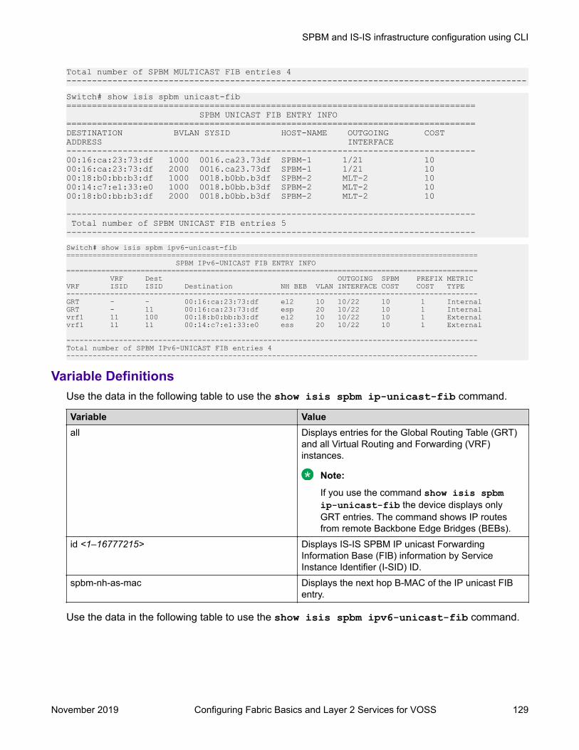
Total number of SPBM MULTICAST FIB entries 4------------------------------------------------------------------------------------------Switch# show isis spbm unicast-fib================================================================================ SPBM UNICAST FIB ENTRY INFO================================================================================DESTINATION BVLAN SYSID HOST-NAME OUTGOING COSTADDRESS INTERFACE--------------------------------------------------------------------------------00:16:ca:23:73:df 1000 0016.ca23.73df SPBM-1 1/21 10 00:16:ca:23:73:df 2000 0016.ca23.73df SPBM-1 1/21 10 00:18:b0:bb:b3:df 1000 0018.b0bb.b3df SPBM-2 MLT-2 10 00:14:c7:e1:33:e0 1000 0018.b0bb.b3df SPBM-2 MLT-2 10 00:18:b0:bb:b3:df 2000 0018.b0bb.b3df SPBM-2 MLT-2 10
-------------------------------------------------------------------------------- Total number of SPBM UNICAST FIB entries 5 --------------------------------------------------------------------------------Switch# show isis spbm ipv6-unicast-fib============================================================================================== SPBM IPv6-UNICAST FIB ENTRY INFO============================================================================================== VRF Dest OUTGOING SPBM PREFIX METRICVRF ISID ISID Destination NH BEB VLAN INTERFACE COST COST TYPE----------------------------------------------------------------------------------------------GRT - - 00:16:ca:23:73:df el2 10 10/22 10 1 InternalGRT - 11 00:16:ca:23:73:df esp 20 10/22 10 1 Internalvrf1 11 100 00:18:b0:bb:b3:df el2 10 10/22 10 1 Externalvrf1 11 11 00:14:c7:e1:33:e0 ess 20 10/22 10 1 External
----------------------------------------------------------------------------------------------Total number of SPBM IPv6-UNICAST FIB entries 4----------------------------------------------------------------------------------------------
Variable DefinitionsUse the data in the following table to use the show isis spbm ip-unicast-fib command.
Variable Valueall Displays entries for the Global Routing Table (GRT)
and all Virtual Routing and Forwarding (VRF)instances.
Note:
If you use the command show isis spbmip-unicast-fib the device displays onlyGRT entries. The command shows IP routesfrom remote Backbone Edge Bridges (BEBs).
id <1–16777215> Displays IS-IS SPBM IP unicast ForwardingInformation Base (FIB) information by ServiceInstance Identifier (I-SID) ID.
spbm-nh-as-mac Displays the next hop B-MAC of the IP unicast FIBentry.
Use the data in the following table to use the show isis spbm ipv6-unicast-fib command.
SPBM and IS-IS infrastructure configuration using CLI
November 2019 Configuring Fabric Basics and Layer 2 Services for VOSS 129

Variable Valueall Displays entries for the Global Routing Table (GRT)
and all Virtual Routing and Forwarding (VRF)instances.
Note:
If you use the command show isis spbmipv6-unicast-fib the device displays onlyGRT entries. The command shows IPv6 routesfrom remote Backbone Edge Bridges (BEBs).
id <1–16777215> Displays IS-IS SPBM IPv6 unicast ForwardingInformation Base (FIB) information by ServiceInstance Identifier (I-SID) ID.
spbm-nh-as-mac Displays the next hop as MAC of the IPv6 unicastFIB entry.
Use the data in the following table to use the show isis spbm multicast-fib command.
Variable Valuevlan <1-4059> Displays the FIB for the specified SPBM VLAN.i-sid <1–16777215> Displays the FIB for the specified I-SID.nick-name <x.xx.xx> Displays the FIB for the specified nickname.summary Displays a summary of the FIB.
Use the data in the following table to use the show isis spbm unicast-fib command.
Variable Valueb-mac <0x00:0x00:0x00:0x00:0x00:0x00> Displays the FIB for the specified BMAC.vlan <1-4059> Displays the FIB for the specified SPBM VLAN.summary Displays a summary of the FIB.
Use the data in the following table to use the show isis spbm unicast-tree command.
Variable Value<1-4059> Specifies the SPBM B-VLAN ID.destination <xxxx.xxxx.xxxx> Displays the unicast tree for the specified destination.
Job AidThe following sections describe the fields in the outputs for SPBM multicast FIB, unicast FIB, andunicast tree show commands.
show isis spbm ip-unicast-fibThe following table describes the fields in the output for the show isis spbm ip-unicast-fibcommand.
SPBM and IS-IS infrastructure configuration
November 2019 Configuring Fabric Basics and Layer 2 Services for VOSS 130

Parameter DsecriptionVRF Specifies the VRF ID of the IP unicast FIB entry, 0
indicates NRE.VRF ISID Specifies the I-SID of the IP unicast FIB entry.DEST ISID Specifies the destination I-SID of the IP unicast FIB
entry.Destination Specifies the destination IP address of the IP unicast
FIB entry.NH BEB Specifies the next hop B-MAC of the IP unicast FIB
entry.VLAN Specifies the VLAN of the IP unicast FIB entry.OUTGOING INTERFACE Specifies the outgoing port of the IP unicast FIB.SPBM COST Specifies the B-MAC cost of the IP unicast FIB entry.PREFIX COST Specifies the prefix cost of the IP unicast FIB entry.PREFIX TYPE Specifies the prefix type of the IP unicast FIB entry.IP ROUTE PREFERENCE Specifies the IP route preference of the IP unicast
FIB entry.
show isis spbm ipv6-unicast-fibThe following table describes the fields in the output for the show isis spbm ipv6-unicast-fib command.
Parameter DsecriptionVRF Specifies the VRF ID of the IPv6 unicast FIB entry, 0
indicates NRE.VRF ISID Specifies the I-SID of the IPv6 unicast FIB entry.DEST ISID Specifies the destination I-SID of the IPv6 unicast
FIB entry.Destination Specifies the destination IPv6 address of the IPv6
unicast FIB entry.NH BEB Specifies the next hop B-MAC of the IPv6 unicast
FIB entry.VLAN Specifies the VLAN of the IPv6 unicast FIB entry.OUTGOING INTERFACE Specifies the outgoing port of the IPv6 unicast FIB.SPBM COST Specifies the B-MAC cost of the IPv6 unicast FIB
entry.PREFIX COST Specifies the prefix cost of the IPv6 unicast FIB
entry.METRIC TYPE Specifies the metric type. Specifies an internal or a
extrenal metric. For internal metric type, the cost ofthe external routes is equal to the sum of all internal
Table continues…
SPBM and IS-IS infrastructure configuration using CLI
November 2019 Configuring Fabric Basics and Layer 2 Services for VOSS 131

Parameter Dsecriptioncosts and the external cost. For external metric type,the cost of the external routes is equal to the externalcost alone. The default is internal.
show isis spbm multicast-fibThe following table describes the fields in the output for the show isis spbm multicast-fibcommand.
Parameter DescriptionMCAST DA Indicates the multicast destination MAC address of the multicast FIB entry.ISID Indicates the I-SID of the multicast FIB entry.BVLAN Indicates the B-VLAN of the multicast FIB entry.SYSID Indicates the system identifier of the multicast FIB entry.HOST-NAME Indicates the host name of the multicast FIB entry.OUTGOING INTERFACE Indicates the outgoing port of the multicast FIB entry.INCOMING INTERFACE Indicates the outgoing port of the multicast FIB entry.
show isis spbm unicast-fibThe following table describes the fields in the output for the show isis spbm unicast-fibcommand.
Parameter DescriptionDESTINATION ADDRESS Indicates the destination MAC Address of the unicast FIB entry.BVLAN Indicates the B-VLAN of the unicast FIB entry.SYSID Indicates the destination system identifier of the unicast FIB entry.HOST-NAME Indicates the destination host name of the unicast FIB entry.OUTGOING INTERFACE Indicates the outgoing interface of the unicast FIB entry.COST Indicates the cost of the unicast FIB entry.
Displaying IS-IS LSDB and adjacenciesUse the following procedure to display the IS-IS LSDB and adjacencies.
Procedure1. To enter User EXEC mode, log on to the switch.
2. Display the IS-IS LSDB:
show isis lsdb [level {l1|l2|l12}] [sysid <xxxx.xxxx.xxxx>] [lspid<xxxx.xxxx.xxxx.xx-xx>] [tlv <1–236>] [detail]
3. Display IS-IS adjacencies:
SPBM and IS-IS infrastructure configuration
November 2019 Configuring Fabric Basics and Layer 2 Services for VOSS 132
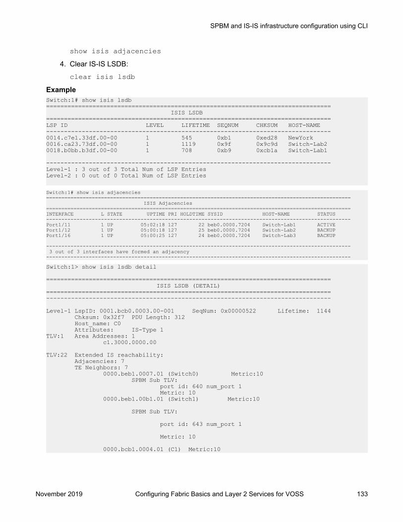
show isis adjacencies4. Clear IS-IS LSDB:
clear isis lsdbExampleSwitch:1# show isis lsdb================================================================================ ISIS LSDB================================================================================LSP ID LEVEL LIFETIME SEQNUM CHKSUM HOST-NAME --------------------------------------------------------------------------------0014.c7e1.33df.00-00 1 545 0xb1 0xed28 NewYork 0016.ca23.73df.00-00 1 1119 0x9f 0x9c9d Switch-Lab2 0018.b0bb.b3df.00-00 1 708 0xb9 0xcb1a Switch-Lab1
--------------------------------------------------------------------------------Level-1 : 3 out of 3 Total Num of LSP EntriesLevel-2 : 0 out of 0 Total Num of LSP Entries
Switch:1# show isis adjacencies==================================================================================================== ISIS Adjacencies====================================================================================================INTERFACE L STATE UPTIME PRI HOLDTIME SYSID HOST-NAME STATUS ----------------------------------------------------------------------------------------------------Port1/11 1 UP 05:02:18 127 22 beb0.0000.7204 Switch-Lab1 ACTIVE Port1/12 1 UP 05:00:18 127 25 beb0.0000.7204 Switch-Lab2 BACKUP Port1/16 1 UP 05:00:25 127 24 beb0.0000.7204 Switch-Lab3 BACKUP
---------------------------------------------------------------------------------------------------- 3 out of 3 interfaces have formed an adjacency----------------------------------------------------------------------------------------------------Switch:1> show isis lsdb detail
================================================================================ ISIS LSDB (DETAIL)================================================================================--------------------------------------------------------------------------------
Level-1 LspID: 0001.bcb0.0003.00-001 SeqNum: 0x00000522 Lifetime: 1144 Chksum: 0x32f7 PDU Length: 312 Host_name: C0 Attributes: IS-Type 1TLV:1 Area Addresses: 1 c1.3000.0000.00
TLV:22 Extended IS reachability: Adjacencies: 7 TE Neighbors: 7 0000.beb1.0007.01 (Switch0) Metric:10 SPBM Sub TLV: port id: 640 num_port 1 Metric: 10 0000.beb1.00b1.01 (Switch1) Metric:10
SPBM Sub TLV:
port id: 643 num_port 1
Metric: 10
0000.bcb1.0004.01 (C1) Metric:10
SPBM and IS-IS infrastructure configuration using CLI
November 2019 Configuring Fabric Basics and Layer 2 Services for VOSS 133

SPBM Sub TLV:
port id: 6144 num_port 1
Metric: 10
0000.beb1.00ca.01 (Switch2) Metric:10
SPBM Sub TLV:
port id: 6156 num_port 1
Metric: 10
0000.beb1.00a5.01 (VSS0) Metric:10
SPBM Sub TLV:
port id: 651 num_port 1
Metric: 10
0000.beb1.00b2.01 (VSS1) Metric:10
SPBM Sub TLV:
port id: 645 num_port 1
Metric: 10
0000.beb1.0008.01 (Switch1) Metric:10
SPBM Sub TLV:
port id: 652 num_port 1
Metric: 10
TLV:129 Protocol Supported: SPBM
TLV:137 Host_name: C0#
TLV:144 SUB-TLV 1 SPBM INSTANCE: Instance: 0 bridge_pri: 0 OUI: 00-33-33 num of trees: 2 vid tuple : u-bit 1 m-bit 1 ect-alg 0x80c201 base vid 1000 vid tuple : u-bit 1 m-bit 1 ect-alg 0x80c202 base vid 1001TLV:144 SUB-TLV 3 ISID: Instance: 0 Metric: 0 B-MAC: 00-00-bc-b1-00-03 BVID:1000 Number of ISID's:8 3001(Both),3002(Rx),3003(Both),3004(Rx),4001(Both),4002(Rx),4003(Both),4004(Rx)
Instance: 0 Metric: 0 B-MAC: 00-00-bc-b1-00-03
--More-- (q = quit)
SPBM and IS-IS infrastructure configuration
November 2019 Configuring Fabric Basics and Layer 2 Services for VOSS 134

Variable DefinitionsUse the data in the following table to use the show isis lsdb command.
Variable Valuedetail Displays detailed information.level {l1|l2|l12}] Displays the LSDB for the specified level: l1, l2, or l12.local Displays IS-IS local LSDB information.sysid <xxxx.xxxx.xxxx> Displays the LSDB for the specified system ID.lspid <xxxx.xxxx.xxxx.xx-xx> Displays the LSDB for the specified LSP ID.tlv <1–236> Displays the LSDB by TLV type.
Use the data in the following table to use the clear isis command.
Variable Valuelsdb Clears the IS-IS Link State Database (LSDB). The
command clears learned LSPs only. The commanddoes not clear local generated LSPs. As soon as theplatform clears the LSDB the LSP synchronizationprocess starts immediately and the LSDBsynchronizes with its neighbors.
Job AidThe following sections describe the fields in the outputs for the IS-IS LSDB and adjacencies showcommands.
show isis lsdbThe following table describes the fields in the output for the show isis lsdb command.
Parameter DescriptionLSP ID Indicates the LSP ID assigned to external IS-IS routing devices.LEVEL Indicates the level of the external router: l1, l2, or l12.LIFETIME Indicates the maximum age of the LSP. If the max-lsp-gen-interval is set to
900 (default) then the lifetime value begins to count down from 1200seconds and updates after 300 seconds if connectivity remains. If the timercounts down to zero, the counter adds on an additional 60 seconds, thenthe LSP for that router is lost. This happens because of the zero agelifetime, which is detailed in the RFC standards.
SEQNUM Indicates the LSP sequence number. This number changes each time theLSP is updated.
CHKSUM Indicates the LSP checksum. This is an error checking mechanism used toverify the validity of the IP packet.
HOST-NAME Indicates the hostname listed in the LSP. If the host name is not configured,then the system name is displayed.
SPBM and IS-IS infrastructure configuration using CLI
November 2019 Configuring Fabric Basics and Layer 2 Services for VOSS 135

show isis adjacenciesThe following table describes the fields in the output for the show isis adjacencies command.
Parameter DescriptionINTERFACE Indicates the interface port, MLT, or logical interface on which IS-IS exists.L Indicates the level of the adjacent router.STATE Indicates the state of IS-IS on the interface (enabled [UP] or disabled
[DOWN]). The state is non-configurable.UPTIME Indicates the length of time the adjacency has been up in ddd hh:mm:ss
format.PRI Indicates the priority of the neighboring Intermediate System for becoming
the Designated Intermediate System (DIS).HOLDTIME Indicates the calculated hold time for the Hello (hello multiplier x hello
interval); if the route is determined to be a designated router, then theproduct is divided by 3.
SYSID Indicates the adjacent system ID of the router.HOST-NAME Indicates the hostname listed in the LSP. If the host name is not configured,
then the system name is displayed.STATUS Indicates if the adjacency is active.
Displaying IS-IS Statistics and CountersUse the following procedure to display the IS-IS statistics and counters.
Procedure1. Display IS-IS system statistics:
show isis statistics2. Display IS-IS interface counters:
show isis int-counters3. Display IS-IS level 1 control packet counters:
show isis int-l1-cntl-pkts
Note:
The switch uses level 1 IS-IS. The switch does not support level 2 IS-IS. The commandshow isis int-l2-contl-pkts is not supported because the IEEE 802.1aqstandard currently only defines the use of one hierarchy, Level 1.
4. Clear IS-IS statistics:
clear isis stats [error-counters] [packet-counters]
SPBM and IS-IS infrastructure configuration
November 2019 Configuring Fabric Basics and Layer 2 Services for VOSS 136

ExampleSwitch:1# show isis statistics================================================================================ ISIS System Stats================================================================================
LEVEL CORR AUTH AREA MAX SEQ SEQ NUM OWN LSP BAD ID PART LSP DB LSPs FAILS DROP EXCEEDED SKIPS PURGE LEN CHANGES OLOAD --------------------------------------------------------------------------------Level-1 0 0 0 0 1 0 0 0 0 Switch:1# show isis int-counters================================================================================ ISIS Interface Counters================================================================================
IFIDX LEVEL AUTH ADJ INIT REJ ID LEN MAX AREA LAN DIS FAILS CHANGES FAILS ADJ CHANGES --------------------------------------------------------------------------------Mlt2 Level 1-2 0 1 0 0 0 0 0 Port1/21 Level 1-2 0 1 0 0 0 0 0
Switch:1# show isis int-l1-cntl-pkts================================================================================ ISIS L1 Control Packet counters================================================================================IFIDX DIRECTION HELLO LSP CSNP PSNP
--------------------------------------------------------------------------------Mlt2 Transmitted 13346 231 2 229 Mlt2 Received 13329 230 1 230 Port1/21 Transmitted 13340 227 2 226 Port1/21 Received 13335 226 1 227
Variable DefinitionsUse the data in the following table to use the clear isis stats command.
Variable Valueerror-counters Clears IS-IS stats error-counters.packet-counters Clears IS-IS stats packet-counters.
Job Aidshow isis statisticsThe following table describes the fields in the output for the show isis statistics command.
Parameter DescriptionLEVEL Shows the level of the IS-IS interface.CORR LSPs Shows the number of corrupted LSPs detected.AUTH FAILS Shows the number of times authentication has failed on the global level.AREA DROP Shows the number of manual addresses dropped from the area.
Table continues…
SPBM and IS-IS infrastructure configuration using CLI
November 2019 Configuring Fabric Basics and Layer 2 Services for VOSS 137

Parameter DescriptionMAX SEQ EXCEEDED Shows the number of attempts to exceed the maximum sequence number.SEQ NUM SKIPS Shows the number of times the sequence number was skipped.OWN LSP PURGE Shows how many times the local LSP was purged.BAD ID LEN Shows the number of ID field length mismatches.PART CHANGES Shows the number of partition link changes.LSP DB OLOAD Show the number of times the switch was in the overload state.
show isis int-countersThe following table describes the fields in the output for the show isis int-counterscommand.
Parameter DescriptionIFIDX Shows the interface index for the Ethernet or MLT interface.LEVEL Shows the level of the IS-IS interface.AUTH FAILS Shows the number of times authentication has failed per interface.ADJ CHANGES Shows the number of times the adjacencies have changed.INIT FAILS Shows the number of times the adjacency has failed to establish.REJ ADJ Shows the number of times the adjacency was rejected by another router.ID LEN Shows the ID field length mismatches.MAX AREA Shows the maximum area address mismatches.LAN DIS CHANGES Shows the number of times the DIS has changed.
show isis int-l1-cntl-pktsThe following table describes the fields in the output for the show isis int-l1-cntl-pktscommand.
Parameter DescriptionIFIDX Shows the interface index for the Ethernet or MLT interface.DIRECTION Shows the packet flow (Transmitted or Received).HELLO Shows the amount of interface-level Hello packets.LSP Shows the amount of LSP packets.CSNP Shows the amount of CSNPs.PSNP Shows the amount of PSNPs.
Running the Layer 2 Video Surveillance install scriptUse the following procedure to run the install script using the syntax parameter, which displays therun commands and any errors.
SPBM and IS-IS infrastructure configuration
November 2019 Configuring Fabric Basics and Layer 2 Services for VOSS 138

Before you beginThe switch must be in the factory default state before executing the install script. When you start theinstall script, a prompt appears to remind you to do this.
Procedure1. Enter Global Configuration mode:
enableconfigure terminal
2. Run the install script:
run vms layer-2 switch <5–99> [syntax]The script uses the value that you assign to the switch number (between 5 and 99) to seedunique values in the configuration script.
Note:
If the script causes a configuration conflict or cannot run a command, an error messagedisplays but the script continues to run.
ExampleThe following example shows the complete output of the install script without the syntaxparameter. As you can see, there is no indication that the script encountered any errors.Switch:1>enableSwitch:1#config terminalEnter configuration commands, one per line. End with CNTL/Z.
Switch:1(config)# run vms layer-2 switch 6
Do you want to execute the run vms layer-2 script? Device needs to be in factory default state. (y/n) ? y
**Previous configurations stored in pre_vms_layer2_install.cfg****New VMS configurations stored in new primary config file vms-layer2-switch-6.cfg***** VMS Layer-2 script execution complete ***Switch:1(config)#boot config choice primary config-file /intflash/vms-layer2-switch-6.cfg
The following displays the output of the script using the syntax parameter. This example is only asmall sample of the output, but it shows how the script reports warnings and errors it encounters.Switch:1>enableSwitch:1#config terminalEnter configuration commands, one per line. End with CNTL/Z.
Switch:1(config)# run vms layer-2 switch 6 syntax
Do you want to execute the run vms layer-2 script? Device needs to be in factory default state. (y/n) ? y
Switch:1(config)# save config file pre_vms_layer2_install.cfgFile [/intflash/pre_vms_layer2_install.cfg] already existing,CP-1: Save config to file /intflash/pre_vms_layer2_install.cfg successful.WARNING: Choice Primary Node Config file is "/intflash/vms-layer2-switch-6.cfg".
SPBM and IS-IS infrastructure configuration using CLI
November 2019 Configuring Fabric Basics and Layer 2 Services for VOSS 139

Switch:1(config)# spbmSwitch:1(config)# spbm ethertype 0x8100Switch:1(config)# router isisSwitch:1(config-isis)# spbm 1
Error: ISIS - IS-IS is enabled, runtime change not allowed.
Switch:1(config)# exit
Switch:1(config)# save config file vms-layer2-switch-6.cfgFile [/intflash/vms-layer2-switch-6.cfg] already existing,CP-1: Save config to file /intflash/vms-layer2-switch-6.cfg successful.
Switch:1(config)# boot config choice primary config-file /intflash/vms-layer2-switch-6.cfgSwitch:1(config)#**Previous configurations stored in pre_vms_layer2_install.cfg****New VMS configurations stored in new primary config file vms-layer2-switch-6.cfg***** VMS Layer-2 script execution complete ***Switch:1(config)#boot config choice primary config-file /intflash/vms-layer2-switch-6.cfg
Variable definitionsUse the data in the following table to use the run vms layer-2 switch command.
Variable Value<5-99> Specifies a switch value, which is then used as a common
element to configure switch parameters such as nickname,VLAN ID, SPB and IP parameters.
This switch value is also used in the name of the savedconfiguration file. For example, 6 is the switch value in vms-layer2-switch-6.cfg.
syntax Lists all the commands run by the script.
Note:
The script does not stop if it encounters errors. To verifythat the script runs without errors, use the syntaxparameter to display errors or conflicting configurations onthe switch.
Fabric Extend configuration using the CLIThe following sections provide procedural information you can use to configure Fabric Extend (FE)using the Command Line Interface (CLI).
Configuring Fabric ExtendUse the following procedure to configure Fabric Extend (FE) between a Main office to a Branchoffice. This is a typical deployment. However, if your deployment creates tunnels between twoswitches that support Fabric Extend natively, then repeat those steps and ignore the steps forswitches that require an ONA.
SPBM and IS-IS infrastructure configuration
November 2019 Configuring Fabric Basics and Layer 2 Services for VOSS 140

Note:
VRF is an optional parameter. If a VRF is not configured, then FE uses the GRT.
Before you beginThe tunnel source IP address can be either a brouter port interface or a CLIP IP.If using the tunnel originating address on the GRT, Fabric Extend has the following requirements:
• The tunnel source IP address must be on the GRT, not on a VRF.
Note:A Best Practice is to use separate IP addresses for the SPBM IP Shortcuts ip-source-address command and the Fabric Extend ip-tunnel-source-address command.However, if you want these IP addresses to be the same, you MUST exclude the ip-source-address address with an IS-IS accept policy. You cannot use the redistributecommand with a route map exclusion.Specify a CLIP interface to use as the source address for SPBM IP shortcuts.
• If IP Shortcuts is enabled, you must configure an IS-IS accept policy or exclude route-map toensure that tunnel destination IP addresses are not learned through IS-IS.
If you are using the tunnel originating address on a VRF, Fabric Extend has the followingrequirements:
• Configure a CLIP and tunnel source IP address on the VRF.• Remote management of the VSP 4000 is only possible after establishing IP Shortcut over IS-
IS. (Alternatively, you can enable GRT-VRF redistribution locally.)
About this taskConfiguring Fabric Extend consists of two primary tasks: configuring the tunnel source address andconfiguring the logical interface. These tasks must be completed on both ends of the tunnel.Note that the VSP 4000 source address command is different than other platforms. Also note thatthe logical interface commands are different between Layer 2 and Layer 3 networks.
ProcedureThe following steps are for platforms that support FE natively:1. Enter IS-IS Router Configuration mode:
enableconfigure terminalrouter isis
2. Configure the IP tunnel source address:
ip-tunnel-source-address <A.B.C.D> [vrf WORD<1–16>]3. Enter Global Configuration mode:
exit
SPBM and IS-IS infrastructure configuration using CLI
November 2019 Configuring Fabric Basics and Layer 2 Services for VOSS 141

4. Use one of the following commands to create a logical IS-IS interface:
• In a network with a Layer 3 Core, enter logical-intf isis <1–255> dest-ip<A.B.C.D> [name WORD<1–16>]
• In a network with a Layer 2 Core, enter logical-intf isis <1–255> vid <listof vids> primary-vid <2–4059> port <slot/port> mlt <mltId> [nameWORD<1–16>]
Note:
The primary VLAN ID (primary-vid must be one of the VIDs in the vid <list ofvids>.
The following steps are for platforms that require an ONA to support FE:
Note:
The interface VLAN connecting to the ONA network port is always in the GRT and themember port that the VLAN is part of is always an access port.
5. Enter IS-IS Router Configuration mode:
enableconfigure terminalrouter isis
6. Configure the IP tunnel source address on the port that connects to the Device side of theONA:
ip-tunnel-source-address <A.B.C.D> port <slot/port> [mtu<mtu_value>] [vrf WORD<1–16>]
7. Exit back into Global Configuration mode:
exit8. Use one of the following commands to create a logical IS-IS interface:
• In a network with a Layer 3 Core, enter:
logical-intf isis <1–255> dest-ip <A.B.C.D> [name WORD<1–16>]• In a network with a Layer 2 Core, enter:
logical-intf isis <1–255> vid <list of vids> primary-vid <2–4059>port <slot/port> mlt <mltId> [name WORD<1–16>]
Note:
The primary VLAN ID (primary-vid) must be one of the VIDs in the vid <listof vids>.
Variable definitionsUse the data in the following tables to use the ip-tunnel-source-address command.
SPBM and IS-IS infrastructure configuration
November 2019 Configuring Fabric Basics and Layer 2 Services for VOSS 142
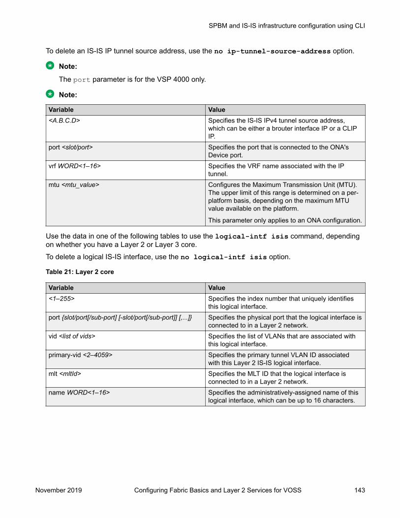
To delete an IS-IS IP tunnel source address, use the no ip-tunnel-source-address option.
Note:
The port parameter is for the VSP 4000 only.
Note:
Variable Value<A.B.C.D> Specifies the IS-IS IPv4 tunnel source address,
which can be either a brouter interface IP or a CLIPIP.
port <slot/port> Specifies the port that is connected to the ONA'sDevice port.
vrf WORD<1–16> Specifies the VRF name associated with the IPtunnel.
mtu <mtu_value> Configures the Maximum Transmission Unit (MTU).The upper limit of this range is determined on a per-platform basis, depending on the maximum MTUvalue available on the platform.
This parameter only applies to an ONA configuration.
Use the data in one of the following tables to use the logical-intf isis command, dependingon whether you have a Layer 2 or Layer 3 core.To delete a logical IS-IS interface, use the no logical-intf isis option.
Table 21: Layer 2 core
Variable Value<1–255> Specifies the index number that uniquely identifies
this logical interface.port {slot/port[/sub-port] [-slot/port[/sub-port]] [,...]} Specifies the physical port that the logical interface is
connected to in a Layer 2 network.vid <list of vids> Specifies the list of VLANs that are associated with
this logical interface.primary-vid <2–4059> Specifies the primary tunnel VLAN ID associated
with this Layer 2 IS-IS logical interface.mlt <mltId> Specifies the MLT ID that the logical interface is
connected to in a Layer 2 network.name WORD<1–16> Specifies the administratively-assigned name of this
logical interface, which can be up to 16 characters.
SPBM and IS-IS infrastructure configuration using CLI
November 2019 Configuring Fabric Basics and Layer 2 Services for VOSS 143

Table 22: Layer 3 core
Variable Value<1–255> Specifies the index number that uniquely identifies
this logical interface.dest-ip <A.B.C.D> Specifies the tunnel destination IP address of the
remote BEB.name WORD<1–16> Specifies the administratively-assigned name of this
logical interface, which can be up to 16 characters.
Configuring Fabric Extend over IPsecUse the following procedure to configure Fabric Extend (FE) over IPsec.
Before you beginThe tunnel source IP address is a brouter port interface.
About this taskConfiguring Fabric Extend over IPsec consists of two primary tasks: configuring the tunnel sourceaddress and configuring the logical interface. These tasks must be completed on both ends of thetunnel.
ProcedureSwitch A Steps1. Enter IS-IS Router Configuration mode:
enableconfigure terminalrouter isis
2. Configure the IP tunnel source address:
ip-tunnel-source-address <A.B.C.D> [vrf WORD<1–16>]3. Enter Global Configuration mode:
exit4. Use one of the following commands to create a logical IS-IS interface:
• In a network with a Layer 3 Core, enter logical-intf isis <1–255> dest-ip<A.B.C.D> [name WORD<1–16>]
• In a network with a Layer 2 Core, enter logical-intf isis <1–255> vid <listof vids> primary-vid <2–4059> port <slot/port> mlt <mltId> [nameWORD<1–16>]
SPBM and IS-IS infrastructure configuration
November 2019 Configuring Fabric Basics and Layer 2 Services for VOSS 144

Note:
The primary VLAN ID (primary-vid must be one of the VIDs in the vid <list ofvids>.
5. Configure an IS-IS interface on the selected ports or MLTs:
a. Create an IS-IS circuit and interface on the selected ports or MLTs:
isisb. Enable the SPBM instance on the IS-IS interfaces:
isis spbm <1–100>c. Enable the IS-IS circuit/interface on the selected ports or MLTs:
isis enable6. Create the authentication key:
auth-key WORD<1-32>7. Enable IPsec on the logical interface:
ipsec8. Exit interface configuration mode:
exitSwitch B Steps9. Enter IS-IS Router Configuration mode:
enableconfigure terminalrouter isis
10. Configure the IP tunnel source address:
ip-tunnel-source-address <A.B.C.D> [vrf WORD<1–16>]11. Enter Global Configuration mode:
exit12. Use one of the following commands to create a logical IS-IS interface:
• In a network with a Layer 3 Core, enter logical-intf isis <1–255> dest-ip<A.B.C.D> [name WORD<1–16>]
• In a network with a Layer 2 Core, enter logical-intf isis <1–255> vid <listof vids> primary-vid <2–4059> port <slot/port> mlt <mltId> [nameWORD<1–16>]
SPBM and IS-IS infrastructure configuration using CLI
November 2019 Configuring Fabric Basics and Layer 2 Services for VOSS 145

Note:
The primary VLAN ID (primary-vid must be one of the VIDs in the vid <list ofvids>.
13. Configure an IS-IS interface on the selected ports or MLTs:
a. Create an IS-IS circuit and interface on the selected ports or MLTs:
isisb. Enable the SPBM instance on the IS-IS interfaces:
isis spbm <1–100>c. Enable the IS-IS circuit/interface on the selected ports or MLTs:
isis enable14. Create the authentication key:
auth-key WORD<1-32>15. Enable IPsec on the logical interface:
ipsec16. Exit interface configuration mode:
exitVariable definitions
Use the data in the following tables to set up Fabric Extend over IPsec on a device.
Use the data in the following table to use the ip-tunnel-source-address command.
Table 23:
Variable Value<A.B.C.D> Specifies the IS-IS IPv4 tunnel source address,
which can be either a brouter interface IP or a CLIPIP.
vrf WORD<1–16> Specifies the VRF name associated with the IPtunnel.
Use the data in the following table to use the logical-interface command.
Table 24: Layer 2 core
Variable Value<1–255> Specifies the index number that uniquely identifies
this logical interface.
Table continues…
SPBM and IS-IS infrastructure configuration
November 2019 Configuring Fabric Basics and Layer 2 Services for VOSS 146

Variable Valueport {slot/port[/sub-port] [-slot/port[/sub-port]] [,...]} Specifies the physical port that the logical interface is
connected to in a Layer 2 network.vid <list of vids> Specifies the list of VLANs that are associated with
this logical interface.primary-vid <2–4059> Specifies the primary tunnel VLAN ID associated
with this Layer 2 IS-IS logical interface.mlt <mltId> Specifies the MLT ID that the logical interface is
connected to in a Layer 2 network.name WORD<1–16> Specifies the administratively-assigned name of this
logical interface, which can be up to 16 characters.
Table 25: Layer 3 core
Variable Value<1–255> Specifies the index number that uniquely identifies
this logical interface.<A.B.C.D> Specifies the IS-IS IPv4 tunnel source address,
which can be either a brouter interface IP or a CLIPIP.
name WORD<1–16> Specifies the administratively-assigned name of thislogical interface, which can be up to 16 characters.
Use the data in the following table to use the isis command.
Variable Valueenable Enables or disables the IS-IS circuit/interface on the
specified port or MLT.
The default is disabled. Use the no option to disableIS-IS on the specified interface.
spbm <1–100> Enable the SPBM instance on the IS-IS interfaces.
Use the data in the following table to use the auth-key command.
Variable ValueWORD<1–32> Specifies the authentication key on the assigned
logical interface, which can be up to 32characters.
Use the no option to disable the authentication keyon the specified interface.
Displaying Fabric Extend over IPsec tunnel statusUse the following procedure to display the Fabric Extend over IPsec tunnel status on the switch.
ProcedureDisplay the Fabric Extend over IPsec tunnel status:
SPBM and IS-IS infrastructure configuration using CLI
November 2019 Configuring Fabric Basics and Layer 2 Services for VOSS 147

show io logical-intf-ipsec
Example of a Fabric Extend over IPsec tunnel status.Switch:1# show io logical-intf-ipsecbash-4.3# ipsec status | grep ESTABLISHEDipsec1-192.0.2.192[12]: ESTABLISHED 13 hours ago, 192.0.2.193[192.0.2.193]...192.0.2.192[192.0.2.192]ipsec0-192.0.2.182[11]: ESTABLISHED 13 hours ago, 192.0.2.193[192.0.2.193]...192.0.2.182[192.0.2.182]
Displaying IS-IS logical interfacesUse the following procedure to display the IS-IS logical interfaces configured on the switch.
ProcedureDisplay the IS-IS logical interfaces:
show isis logical-interface [name | ipsec | shaper]ExamplesExample of a Layer 2 CoreSwitch:1# show isis logical-interface======================================================================================== ISIS Logical Interfaces========================================================================================IFIDX NAME ENCAP L2_INFO TUNNEL L3_TUNNEL_NEXT_HOP_INFO TYPE PORT/MLT VIDS(PRIMARY) DEST-IP PORT/MLT VLAN VRF----------------------------------------------------------------------------------------1 -- L2-P2P-VID Port2/40 101,201(101) -- -- -- --2 -- L2-P2P-VID Port1/3 102,202(102) -- -- -- ------------------------------------------------------------------------------------------ 2 out of 2 Total Num of Logical ISIS interfaces ----------------------------------------------------------------------------------------
Example of a Layer 3 CoreSwitch:1# show isis logical-interface======================================================================================== ISIS Logical Interfaces========================================================================================IFIDX NAME ENCAP L2_INFO TUNNEL L3_TUNNEL_NEXT_HOP_INFO TYPE PORT/MLT VIDS(PRIMARY) DEST-IP PORT/MLT VLAN VRF----------------------------------------------------------------------------------------1 SPBoIP_T1 IP -- -- 41.41.41.41 MLT10 2 vrf24 2 SPBoIP_T2 IP -- -- 42.42.42.42 MLT10 2 vrf24 3 SPBoIP_4K5 IP -- -- 187.187.187.187 MLT10 2 vrf24 ---------------------------------------------------------------------------------------- 3 out of 3 Total Num of Logical ISIS interfaces ----------------------------------------------------------------------------------------
Example showing the full IS-IS logical interface name
SPBM and IS-IS infrastructure configuration
November 2019 Configuring Fabric Basics and Layer 2 Services for VOSS 148

The command show isis logical-interface truncates the IS-IS logical interface name to thefirst 16 characters. To view the entire name (up to a maximum of 64 characters), use the commandshow isis logical-interface name.Switch:1# show isis logical-interface name======================================================================================== ISIS Logical Interface name========================================================================================ID NAME ----------------------------------------------------------------------------------------1 SPBoIP_T1 2 SPBoIP_T2 3 SPBoIP_4K56 This_Is_A_50_Character_ISIS_Logical_Interface_Name ---------------------------------------------------------------------------------------- 4 out of 4 Total Num of Logical ISIS interfaces ----------------------------------------------------------------------------------------
Example showing the authentication keyDisplay the IS-IS logical interface ID and IPsec authentication key. This command only displaysinterfaces with authentication keys configured.
Note:The Authentication-Key is obscured and not visible in plain text output.
Switch:1>show isis logical-interface ipsec======================================================================================== ISIS Logical Interface IPsec========================================================================================ID Authentication-Key----------------------------------------------------------------------------------------1 ********2 ********---------------------------------------------------------------------------------------- 2 out of 2 Total Num of Logical ISIS interfaces----------------------------------------------------------------------------------------
Example showing the IS-IS egress shaping rate valuesDisplay the IS-IS logical interface egress shaping rate values. This command only displaysinterfaces with egress shaping rates configured.Switch:1>show isis logical-interface shaper======================================================================================== ISIS Logical Interface Egress Shaping Rate========================================================================================ID NAME service-rate(Mbps)----------------------------------------------------------------------------------------1 remote1 1352 remote2 1203 remote3 178---------------------------------------------------------------------------------------- 3 out of 3 Total Num of Logical ISIS interfaces----------------------------------------------------------------------------------------
Job AidThe following table describes the fields in the output for the show isis logical interfacecommand.
SPBM and IS-IS infrastructure configuration using CLI
November 2019 Configuring Fabric Basics and Layer 2 Services for VOSS 149
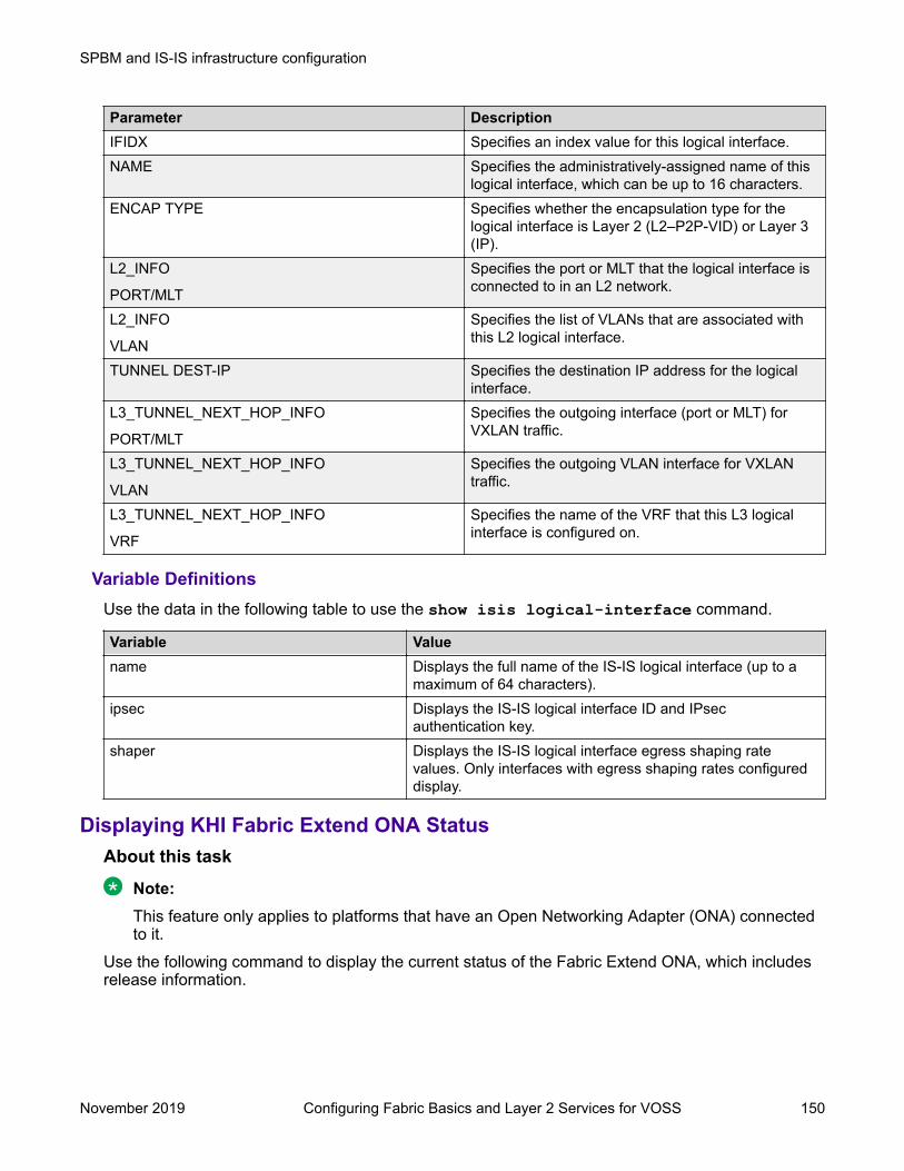
Parameter DescriptionIFIDX Specifies an index value for this logical interface.NAME Specifies the administratively-assigned name of this
logical interface, which can be up to 16 characters.ENCAP TYPE Specifies whether the encapsulation type for the
logical interface is Layer 2 (L2–P2P-VID) or Layer 3(IP).
L2_INFO
PORT/MLT
Specifies the port or MLT that the logical interface isconnected to in an L2 network.
L2_INFO
VLAN
Specifies the list of VLANs that are associated withthis L2 logical interface.
TUNNEL DEST-IP Specifies the destination IP address for the logicalinterface.
L3_TUNNEL_NEXT_HOP_INFO
PORT/MLT
Specifies the outgoing interface (port or MLT) forVXLAN traffic.
L3_TUNNEL_NEXT_HOP_INFO
VLAN
Specifies the outgoing VLAN interface for VXLANtraffic.
L3_TUNNEL_NEXT_HOP_INFO
VRF
Specifies the name of the VRF that this L3 logicalinterface is configured on.
Variable DefinitionsUse the data in the following table to use the show isis logical-interface command.
Variable Valuename Displays the full name of the IS-IS logical interface (up to a
maximum of 64 characters).ipsec Displays the IS-IS logical interface ID and IPsec
authentication key.shaper Displays the IS-IS logical interface egress shaping rate
values. Only interfaces with egress shaping rates configureddisplay.
Displaying KHI Fabric Extend ONA StatusAbout this task
Note:This feature only applies to platforms that have an Open Networking Adapter (ONA) connectedto it.
Use the following command to display the current status of the Fabric Extend ONA, which includesrelease information.
SPBM and IS-IS infrastructure configuration
November 2019 Configuring Fabric Basics and Layer 2 Services for VOSS 150

Procedure1. Enter Privileged EXEC mode:
enable2. Display the ONA status:
show khi fe-ona statusExampleThe following output displays the show khi fe-ona status when the ONA is operatingnormally.Switch:1#show khi fe-ona status
======================================================= ONA STATUS ========================================================ONA Device Status : UPRunning Release Name : v1.0.0.0int006-3-g9749735-dirtyLast Image Upgrade Status : UPGRADE_SUCCESSLast Image File Used For Upgrde: gdb-secure_ona.tgz-------------------------------------------------------
The following examples display the output when communication from the switch to the ONA isdisrupted. Note that the ONA Down reason lists the cause of the failure. The reason changesdepending on the context of the failure.The following output displays when the configuration push from the switch to the ONA fails:Switch:1#show khi fe-ona status
======================================================= ONA STATUS ========================================================ONA Device Status : DOWNONA DOWN reason : ONA_CONFIG_DOWNLOAD_FAILEDRunning Release Name :Image Upgrade Status : UNKNOWN-------------------------------------------------------
The following output displays when the port connecting to the ONA device port is DOWN:Switch:1#show khi fe-ona status
======================================================= ONA STATUS ========================================================ONA Device Status : DOWNONA DOWN reason : ONA_DEVICE_PORT_DOWNRunning Release Name :Image Upgrade Status : UNKNOWNImage File Is Being Used For Upgrade : -------------------------------------------------------
The following output displays when the switch is not receiving LLDP packets from the ONA:Switch:1#show khi fe-ona status
======================================================= ONA STATUS ========================================================
SPBM and IS-IS infrastructure configuration using CLI
November 2019 Configuring Fabric Basics and Layer 2 Services for VOSS 151

ONA Device Status : DOWNONA DOWN reason : ONA_LLDP_TIMEOUTRunning Release Name :Image Upgrade Status : UNKNOWN-------------------------------------------------------
Note:On the switch console, the following log message precedes all three of the above cases:CP1 [03/22/71 09:30:15.336:UTC] 0x00378601 00000000 GlobalRouter ONAWARNING ONA device status detected down
Displaying KHI Fabric Extend ONA Global InformationAbout this task
Note:This feature only applies to platforms that have an Open Networking Adapter (ONA) connectedto it.
Use the following command to display Fabric Extend ONA global information such as port numbers,IP addresses, and MTU.
Procedure1. Enter Privileged EXEC mode:
enable2. Display the ONA global information:
show khi fe-ona detailExampleSwitch:1#show khi fe-ona detail
========================================================= ONA RUNTIME INFORMATION =========================================================ONA Port Number : 1/15ONA Management Address : 100.1.1.11Tunnel Source IP Address : 198.51.100.11ONA LLDP Port Status : EnabledONA Device Port Status : UPONA Device Status : UPMTU : 1000ONA Network Port Number : 1/35ONA Mac(ARP) Address : 10:cd:ae:69:b6:50ONA Source VlanId : 1050ONA Source VlanIP : 192.0.2.1ONA Gateway IP : 192.0.2.1ONA Management IP Mask : 255.255.255.0ONA Bootmode : 1ONA Uptime : 0 day(s), 00:00:00pbit-to-dscp-map p0=16 p1=20 p2=24 p3=30 p4=36 p5=40 p6=48 p7=46---------------------------------------------------------
SPBM and IS-IS infrastructure configuration
November 2019 Configuring Fabric Basics and Layer 2 Services for VOSS 152

Note:In the above example, the switch receives LLDP packets with the Management IP address ofthe ONA over the ONA Port (1/15). The switch extracts the ONA Management IP from the LLDPpacket and resolves the ARP of the ONA over the network port (1/35). After the switch resolvesthe ARP of the ONA IP, the show khi fe-ona detail updates the following details:
• ONA Network Port Number• ONA Mac(ARP) Address• ONA Source VlanId
Note the following in regard to the show khi fe-ona detail output shown above:
• ONA Source VlanIP : 192.0.2.1—This is the IP address of the switch VLAN thatswitches traffic to the ONA network port. In the above output, this is VLAN 1050.
• ONA Gateway IP : 192.0.2.1—This is the ONA gateway IP address that the switchgets by querying the ONA. The ONA receives this gateway IP from the DHCP server.
Important:The ONA Source VlanIP, and ONA Gateway IP addresses must be the same for thetunnels to come up and the traffic to switch.
Fabric Attach configuration using the CLIThe following sections provide procedural information you can use to configure Fabric Attach (FA)and Logical Link Discovery Protocol (LLDP) using the Command Line Interface (CLI).
Configuring Fabric Attach globallyFor proper operation, FA must be enabled at both the global level and at the interface level on theFA Server. By default, FA is globally enabled. However, FA is disabled by default at the interfacelevel and must be explicitly enabled on each interface.
Use this procedure to enable Fabric Attach globally on a switch.
Procedure1. Enter Global Configuration mode:
enableconfigure terminal
2. Enable FA:
fa enable3. (Optional) Disable FA:
no fa enable
SPBM and IS-IS infrastructure configuration using CLI
November 2019 Configuring Fabric Basics and Layer 2 Services for VOSS 153

Caution:
Disabling FA flushes all FA element discovery and mappings.
4. View the FA configuration status. Use one of the following commands:
• show fa• show fa agent
ExampleSwitch:1>enSwitch:1#conf tEnter configuration commands, one per line. End with CNTL/Z.Switch:1(config)#fa enableSwitch:1(config)#show fa
================================================================================ Fabric Attach Configuration================================================================================ FA Service : enabled FA Element Type : server FA Assignment Timeout : 240 FA Discovery Timeout : 240 FA Provision Mode : spbm
Switch:1(config)#show fa agent
================================================================================ Fabric Attach Configuration================================================================================ FA Service : enabled FA Element Type : server FA Assignment Timeout : 240 FA Discovery Timeout : 240 FA Provision Mode : spbm
Configuring Fabric Attach discovery timeoutUse this procedure to configure the Fabric Attach discovery time-out.
Procedure1. Enter Global Configuration mode:
enableconfigure terminal
2. Configure the FA discovery time-out in seconds:
fa discovery-timeout <45–480>
Note:
The discovery time-out must be greater than or equal to the assignment time-out.
3. (Optional) Configure the default FA discovery time-out:
default fa discovery-timeout
SPBM and IS-IS infrastructure configuration
November 2019 Configuring Fabric Basics and Layer 2 Services for VOSS 154

ExampleConfigure the FA discovery time-out.Switch:1>enSwitch:1#conf tEnter configuration commands, one per line. End with CNTL/Z.Switch:1(config)#fa discovery-timeout 50
Verify the configuration.Switch:1(config)#show fa
======================================================================= Fabric Attach Configuration======================================================================= FA Service : enabled FA Element Type : server FA Assignment Timeout : 45 FA Discovery Timeout : 50 FA Provision Mode : spbm
Variable definitionsUse the data in the following table to use the fa discovery-timeout command.
Variable Value<45–480> Specifies the Fabric Attach discovery time-out in
seconds.
The default value is 240 seconds.
Configuring Fabric Attach assignment timeoutUse this procedure to configure the Fabric Attach assignment time-out.
Procedure1. Enter Global Configuration mode:
enableconfigure terminal
2. Configure the FA assignment time-out in seconds:
fa assignment-timeout <45–480>
Note:
The assignment time-out must be less than or equal to the discovery time-out.
3. (Optional) Configure the default FA assignment time-out value:
default fa assignment-timeoutExampleConfigure the FA assignment time-out:Switch:1>enSwitch:1#conf t
SPBM and IS-IS infrastructure configuration using CLI
November 2019 Configuring Fabric Basics and Layer 2 Services for VOSS 155

Enter configuration commands, one per line. End with CNTL/Z.Switch:1(config)#fa assignment-timeout 50
Verify the configuration:Switch:1(config)#show fa
====================================================================== Fabric Attach Configuration====================================================================== FA Service : enabled FA Element Type : server FA Assignment Timeout : 50 FA Discovery Timeout : 240 FA Provision Mode : spbm
Variable definitionsUse the data in the following table to use the fa assignment-timeout command.
Variable Value<45–480> Specifies the Fabric Attach assignment time-out in
seconds.
The default value is 240 seconds.
Enabling Fabric Attach on an interfaceUse this procedure to enable Fabric Attach on an interface (port, static MLT or LACP MLT). EnablingFA on an MLT enables FA on all ports of the MLT. If your platform supports channelization, FA canalso be enabled on channelized ports.
Before you beginVerify that FA is enabled globally on the switch.
About this taskEnabling FA on a port or MLT is necessary for element discovery.On the FA Server, FA is enabled globally by default. However, you must explicitly enable FA on thedesired port or MLT interface. FA is successfully enabled on an MLT only if all ports of the MLT haveFA successfully enabled. Enabling FA automatically configures LLDP on all ports. Tagging isconfigured and spanning tree is disabled.
Procedure1. Enter Interface Configuration mode:
enableconfigure terminalinterface GigabitEthernet {slot/port[/sub-port][-slot/port[/sub-port]][,...]} or interface mlt <1-512>
SPBM and IS-IS infrastructure configuration
November 2019 Configuring Fabric Basics and Layer 2 Services for VOSS 156

Note:
If your platform supports channelization and the port is channelized, you must alsospecify the sub-port in the format slot/port/sub-port.
2. Enable FA on the interface:
fa enable3. (Optional) Disable FA on the interface:
no fa enable
Caution:
Disabling FA flushes all FA element discovery and I-SID-to-VLAN mappings associatedwith the interface.
4. View the FA configuration status:
show fa interface [disabled-auth] [enabled-auth] [mlt <1–512>] [port<{slot/port[/sub-port] [-slot/port[/sub-port]] [,...]}>]
ExampleEnable FA on a port:Switch:1>enSwitch:1#conf tEnter configuration commands, one per line. End with CNTL/Z.Switch:1(config)#interface gigabitethernet 1/2Switch:1(config-if)#fa enableSwitch:1(config-if)#exitSwitch:1(config)#
Enable FA on an MLT:Switch:1>enSwitch:1#conf tEnter configuration commands, one per line. End with CNTL/Z.Switch:1(config)#interface mlt 10Switch:1(config-mlt)#fa enableSwitch:1(config-mlt)#exitSwitch:1(config)#
Verify that FA is enabled on the interfaces.
Note:When FA is enabled, message authentication is enabled by default. The authentication key isset to the default value and appears encrypted on the output.
Switch:1(config)#show fa interface =================================================================== Fabric Attach Interfaces ===================================================================INTERFACE SERVER MGMT MGMT MSG AUTH MSG AUTH STATUS ISID CVID STATUS KEY -------------------------------------------------------------------Port1/1 enabled 0 0 enabled ****Port1/2 enabled 0 0 enabled **** Mlt1 enabled 0 0 enabled ****
SPBM and IS-IS infrastructure configuration using CLI
November 2019 Configuring Fabric Basics and Layer 2 Services for VOSS 157

Mlt10 enabled 0 0 enabled **** -------------------------------------------------------------------4 out of 4 Total Num of fabric attach interfaces displayed-------------------------------------------------------------------
For example, disable FA on port 1/1 and Mlt1.Switch:1(config)#interface gigabitethernet 1/1Switch:1(config-if)#no fa enableSwitch:1(config-if)#exitSwitch:1(config)#interface mlt 1Switch:1(config-mlt)#no fa enableSwitch:1(config-mlt)#exit
Verify that FA is disabled on port 1/1 and Mlt1.Switch:1(config)#show fa interface =================================================================== Fabric Attach Interfaces ===================================================================INTERFACE SERVER MGMT MGMT MSG AUTH MSG AUTH STATUS ISID CVID STATUS KEY -------------------------------------------------------------------Port1/1 disabled 0 0 enabled **** Port1/2 enabled 0 0 enabled **** Mlt1 disabled 0 0 enabled **** Mlt10 enabled 0 0 enabled **** -------------------------------------------------------------------4 out of 4 Total Num of fabric attach interfaces displayed-------------------------------------------------------------------
View the FA interfaces that have authentication enabled:Switch:1(config)#show fa interface enabled-auth
====================================================================== Fabric Attach Interfaces======================================================================INTERFACE SERVER MGMT MGMT MSG AUTH MSG AUTH STATUS ISID CVID STATUS KEY ----------------------------------------------------------------------Port1/2 enabled 0 0 enabled **** Mlt10 enabled 0 0 enabled ****----------------------------------------------------------------------2 out of 2 Total Num of fabric attach interfaces displayed----------------------------------------------------------------------
Optionally, disable FA message authentication on 1/1 and Mlt1.Switch:1(config)#interface gigabitethernet 1/1Switch:1(config-if)#no fa message-authenticationSwitch:1(config-if)#exitSwitch:1(config)#interface mlt 1Switch:1(config-mlt)#no fa message-authenticationSwitch:1(config-mlt)#exit
Verify that both FA and FA message authentication are disabled on 1/1 and Mlt1, as indicated bythe SERVER STATUS and MSG AUTH STATUS fields respectively.Switch:1(config)#show fa interface =================================================================== Fabric Attach Interfaces ===================================================================INTERFACE SERVER MGMT MGMT MSG AUTH MSG AUTH
SPBM and IS-IS infrastructure configuration
November 2019 Configuring Fabric Basics and Layer 2 Services for VOSS 158

STATUS ISID CVID STATUS KEY -------------------------------------------------------------------Port1/1 disabled 0 0 disabled **** Port1/2 enabled 0 0 enabled **** Mlt1 disabled 0 0 disabled **** Mlt10 enabled 0 0 enabled **** -------------------------------------------------------------------4 out of 4 Total Num of fabric attach interfaces displayed-------------------------------------------------------------------
View the FA interfaces that have authentication disabled:Switch:1(config)#show fa interface disabled-auth
======================================================================= Fabric Attach Interfaces=======================================================================INTERFACE SERVER MGMT MGMT MSG AUTH MSG AUTH STATUS ISID CVID STATUS KEY -----------------------------------------------------------------------Port1/1 disabled 0 0 disabled **** Mlt1 disabled 0 0 disabled ****-----------------------------------------------------------------------2 out of 2 Total Num of fabric attach interfaces displayed-----------------------------------------------------------------------
Variable definitionsUse the data in the following table to use the show fa interface command.
Variable Valuedisabled-auth Displays the FA interfaces (port or MLT) that have
authentication disabled.enabled-auth Displays the FA interfaces (port or MLT) that have
authentication enabled.<1–512> The valid range for MLT ID.
Displays FA configuration on the specified MLT interface.port {slot/port[/sub-port] [-slot/port[/sub-port]][,...]}
Identifies the slot and port in one of the following formats: asingle slot and port (slot/port), a range of slots and ports (slot/port-slot/port), or a series of slots and ports (slot/port,slot/port,slot/port). If your platform supports channelization andthe port is channelized, you must also specify the sub-port inthe format slot/port/sub-port.
Displays FA configuration on the specified port.
Configuring FA message authentication on an interfaceUse this procedure to configure FA message authentication on an interface (port or MLT).
Procedure1. Enter Interface Configuration mode:
enableconfigure terminal
SPBM and IS-IS infrastructure configuration using CLI
November 2019 Configuring Fabric Basics and Layer 2 Services for VOSS 159

interface GigabitEthernet {slot/port[/sub-port][-slot/port[/sub-port]][,...]} or interface mlt <1-512>
Note:
If your platform supports channelization and the port is channelized, you must alsospecify the sub-port in the format slot/port/sub-port.
2. Configure FA message authentication on a port or MLT:
[default] [no] fa message-authentication
Note:
When FA is enabled, message authentication is enabled by default. The authenticationkey is set to the default value and appears encrypted on the output.
ExampleSwitch:1>enSwitch:1#conf tEnter configuration commands, one per line. End with CNTL/Z.Switch:1(config)#
Enable message authentication on a port.Switch:1(config)#interface gigabitEthernet 1/2
Switch:1(config-if)#fa message-authenticationSwitch:1(config-if)#show fa interface port 1/2
============================================================= Fabric Attach Interfaces=============================================================INTERFACE SERVER MGMT MGMT MSG AUTH MSG AUTH STATUS ISID CVID STATUS KEY -------------------------------------------------------------Port1/2 enabled 0 0 enabled ****
------------------------------------------------------------- 1 out of 1 Total Num of fabric attach interfaces displayed-------------------------------------------------------------Switch:1(config-if)#exitSwitch:1(config)#
Enable message authentication on an MLT.Switch:1(config)#interface mlt 10Switch:1(config-mlt)#fa message-authenticationSwitch:1(config-mlt)#show fa interface mlt 10
=================================================================== Fabric Attach Interfaces===================================================================INTERFACE SERVER MGMT MGMT MSG AUTH MSG AUTH STATUS ISID CVID STATUS KEY -------------------------------------------------------------------Mlt10 enabled 0 0 enabled ****
------------------------------------------------------------------- 1 out of 1 Total Num of fabric attach interfaces displayed-------------------------------------------------------------------
SPBM and IS-IS infrastructure configuration
November 2019 Configuring Fabric Basics and Layer 2 Services for VOSS 160

Switch:1(config-mlt)#exitSwitch:1(config)#
The following example demonstrates disabling message authentication on a port or MLT.Switch:1(config)#interface gigabitEthernet 1/2Switch:1(config-if)#no fa message-authenticationSwitch:1(config-if)exitSwitch:1(config)Switch:1(config)#interface mlt 10Switch:1(config-mlt)#no fa message-authentication
Switch:1(config-mlt)#show fa interface =================================================================== Fabric Attach Interfaces ===================================================================INTERFACE SERVER MGMT MGMT MSG AUTH MSG AUTH STATUS ISID CVID STATUS KEY -------------------------------------------------------------------Port1/2 enabled 0 0 disabled **** Mlt10 enabled 0 0 disabled **** -------------------------------------------------------------------2 out of 2 Total Num of fabric attach interfaces displayed-------------------------------------------------------------------
Configuring the FA authentication key on an interfaceOn the FA Server, you can configure an authentication key on an interface (port, static MLT or LACPMLT), to authenticate a client or proxy device on that interface. The authentication key is stored inencrypted form when you save configuration on the FA Server.
Before you beginEnsure that:
• On the FA Server, FA is enabled globally and also on the interface.• FA message authentication is enabled on the interface.
Note:By default, enabling FA enables message authentication. The authentication key is set tothe default value and appears encrypted on the output.
About this taskUse this procedure to configure an FA authentication key on a specified port or on all ports of anMLT, on the switch. If you do not configure an authentication key, the default value is used. If youspecify a key, the default value is overridden and is stored in encrypted format in a separate fileother than the configuration file, when you execute the save config command.
Caution:For an FA Client or an FA Proxy device to successfully authenticate and attach to the FA Server,the authentication key must match on both the client and the server. If the authentication key ischanged on the FA Server switch, it must correspondingly be changed on the FA Client or Proxyattached to it, for FA to operate properly.
SPBM and IS-IS infrastructure configuration using CLI
November 2019 Configuring Fabric Basics and Layer 2 Services for VOSS 161

Procedure1. Enter Interface Configuration mode:
enableconfigure terminalinterface GigabitEthernet {slot/port[/sub-port][-slot/port[/sub-port]][,...]} or interface mlt <1-512>
Note:
If your platform supports channelization and the port is channelized, you must alsospecify the sub-port in the format slot/port/sub-port.
2. Configure the FA authentication key:
fa authentication-key WORD<0-32>3. (Optional) Configure the default FA authentication key:
default fa authentication-keyExampleSwitch:1>enSwitch:1#conf tEnter configuration commands, one per line. End with CNTL/Z.
Enable FA and message authentication on a port. Configure the authentication key phone-network on the port.Switch:1(config)#interface gigabitEthernet 1/2Switch:1(config-if)#fa enableSwitch:1(config-if)#fa message-authenticationSwitch:1(config-mlt)#fa authentication-key phone-networkSwitch:1(config-if)#exitSwitch:1(config)#
Enable FA and message authentication on an MLT. Configure the authentication key client-network on the MLT.Switch:1(config)#interface mlt 10Switch:1(config-mlt)#fa enableSwitch:1(config-mlt)#fa message-authenticationSwitch:1(config-mlt)#fa authentication-key client-network
Verify configuration of the FA authentication key. The authentication key appears encrypted on theoutput.Switch:1(config-if)#show fa interface
============================================================== Fabric Attach Interfaces==============================================================INTERFACE SERVER MGMT MGMT MSG AUTH MSG AUTH STATUS ISID CVID STATUS KEY --------------------------------------------------------------Port1/2 enabled 0 0 enabled **** MLT10 enabled 0 0 enabled ****
--------------------------------------------------------------
SPBM and IS-IS infrastructure configuration
November 2019 Configuring Fabric Basics and Layer 2 Services for VOSS 162

2 out of 2 Total Num of fabric attach interfaces displayed--------------------------------------------------------------
Variable DefinitionsUse the data in the following table to use the fa authentication-key command.
Variable ValueWORD<0–32> Specifies the authentication key on the port or MLT.
Configuring FA management on a port or MLTUse this procedure to configure a management I-SID on an FA enabled port or MLT on the switch.
Before you beginEnsure that the port or MLT is enabled for Fabric Attach.
About this taskThis command applies to all traffic sent or received on a port or MLT, carrying the VLAN ID specifiedusing the c-vid parameter. This parameter is optional.
Depending on whether the c-vid parameter is specified or not, the behavior is as follows:
• If the c-vid parameter is specified, the FA Server transmits this VLAN ID as the managementVLAN in the FA Element TLV. A client or proxy receiving this TLV uses this VLAN-ID formanagement traffic on the FA Server uplink.
• If the c-vid parameter is not specified, the FA Server transmits a management VLAN with aVLAN ID value of 4095 in the FA Element TLV. A client or proxy receiving this TLV usesuntagged traffic for network management on the FA Server uplink.
Procedure1. Enter Interface Configuration mode:
enableconfigure terminalinterface GigabitEthernet {slot/port[/sub-port][-slot/port[/sub-port]][,...]} or interface mlt <1-512>
Note:
If your platform supports channelization and the port is channelized, you must alsospecify the sub-port in the format slot/port/sub-port.
2. Configure the FA management I-SID:
fa management i-sid <i-sid><c-vid>Important:
If you do not specify a C-VID value, the port or MLT is untagged.
SPBM and IS-IS infrastructure configuration using CLI
November 2019 Configuring Fabric Basics and Layer 2 Services for VOSS 163

3. Delete FA management I-SID on a port or MLT using one of the following commands:
• default fa management i-sid• no fa management i-sid
4. Verify configuration of FA management on the port or MLT, using the following commands:
• show i—sid <i-sid>• show interfaces gigabitEthernet i-sid [{slot/port[/sub-port] [-slot/port[/sub-port]] [,...]}]
• show mlt i-sid [<1–512>]ExampleThe following example demonstrates configuring FA management on the port 1/2.Configure FA management on port 1/2:Switch:1>enSwitch:1#conf tEnter configuration commands, one per line. End with CNTL/Z.Switch:1(config)#interface gigabitethernet 1/2Switch:1(config-if)#fa management i-sid 101 c-vid 101Switch:1(config-if)#show i-sid 101
========================================================================================== Isid Info==========================================================================================ISID ISID PORT MLT ORIGINID TYPE VLANID INTERFACES INTERFACES------------------------------------------------------------------------------------------101 ELAN N/A c101:1/2 - MANAGEMENT
Switch:1(config-if)#show interfaces gigabitEthernet i-sid ======================================================================= PORT Isid Info======================================================================= ISID ISID PORTNUM IFINDEX ID VLANID C-VID TYPE ORIGIN BPDU -----------------------------------------------------------------------1/2 193 101 N/A 101 ELAN MANAGEMENT -----------------------------------------------------------------------
1 out of 1 Total Num of i-sid endpoints displayed
The following example demonstrates configuring FA management on an MLT.Configure FA management on MLT 10.Switch:1>enSwitch:1#conf tEnter configuration commands, one per line. End with CNTL/Z.Switch:1(config)#interface mlt 10Switch:1(config-mlt)#fa management i-sid 100
Verify configuration of FA management on the MLT. Since the C-VID is not specified, the MLT isdisplayed as untagged.Switch:1(config-mlt)#show i-sid 100
==========================================================================================
SPBM and IS-IS infrastructure configuration
November 2019 Configuring Fabric Basics and Layer 2 Services for VOSS 164

Isid Info==========================================================================================ISID ISID PORT MLT ORIGINID TYPE VLANID INTERFACES INTERFACES------------------------------------------------------------------------------------------100 ELAN N/A - u:10 MANAGEMENT
An FA management I-SID can have a platform VLAN associated with it. For Layer 3 support on themanagement I-SID, you must create a platform VLAN by port and associate the platform VLAN withthe management I-SID. The C-VID can be of the same value or of a different value than that of theplatform VLAN.If the management I-SID matches one of the FA Switched UNI (ELAN) I-SIDs (as displayed by thecommand show i-sid elan), then the platform VLAN is automatically associated with theFA enabled interface (port or MLT).In the following example, for Layer 3 support, create a platform VLAN 999 and associate it with themanagement I-SID 101.Switch:1(config-if)#vlan create 999 type port-mstprstp 0Switch:1(config-if)#vlan i-sid 999 101Switch:1(config-if)#show i-sid ========================================================================================== Isid Info==========================================================================================ISID ISID PORT MLT ORIGINID TYPE VLANID INTERFACES INTERFACES ------------------------------------------------------------------------------------------101 ELAN 999 c101:1/2 - MANAGEMENT c: customer vid u: untagged-trafficAll 1 out of 1 Total Num of i-sids displayed
Switch:1(config-if)#show vlan i-sid ================================================================================ Vlan I-SID================================================================================VLAN_ID I-SID --------------------------------------------------------------------------------999 101 1 out of 1 Total Num of Vlans displayed
Since the management I-SID matches one of the FA Switched UNI (ELAN) I-SIDs, the platformVLAN is automatically associated with the FA enabled port 1/2.Switch:1(config-if)#show interfaces gigabitEthernet i-sid ================================================================================ PORT Isid Info================================================================================ ISID ISID PORTNUM IFINDEX ID VLANID C-VID TYPE ORIGIN BPDU --------------------------------------------------------------------------------1/2 193 101 999 101 ELAN MANAGEMENT -------------------------------------------------------------------------------- 1 out of 1 Total Num of i-sid endpoints displayed
SPBM and IS-IS infrastructure configuration using CLI
November 2019 Configuring Fabric Basics and Layer 2 Services for VOSS 165

Variable DefinitionsUse the data in the following table to use the fa management command.
Variable Valuei-sid <i-sid> Specifies the management I-SID. Different hardware platforms
support different customer I-SID ranges. Use the CLI Help tosee the available range for your switch.
<c-vid> Specifies the customer VLAN ID. Different hardware platformssupport different customer VLAN ID ranges. Use the CLI Help tosee the available range for your switch.
Important:
If you do not specify a C-VID value, the port or MLT isuntagged.
Viewing Fabric Attach global configuration statusUse this procedure to display the Fabric Attach global configuration status on a switch.
Procedure1. Enter Privileged EXEC mode:
enable2. Display the FA configuration status using one of the following commands:
• show fa• show fa agent
ExampleSample output for the show fa command:Switch:1#show fa
=============================================================== Fabric Attach Configuration=============================================================== FA Service : enabled FA Element Type : server FA Assignment Timeout : 240 FA Discovery Timeout : 240 FA Provision Mode : spbm
Sample output for the show fa agent command:Switch:1#show fa agent
================================================================================ Fabric Attach Configuration================================================================================ FA Service : enabled FA Element Type : server FA Assignment Timeout : 240 FA Discovery Timeout : 240 FA Provision Mode : spbm
SPBM and IS-IS infrastructure configuration
November 2019 Configuring Fabric Basics and Layer 2 Services for VOSS 166

Viewing Fabric Attach interface configurationUse this procedure to view FA interface configuration.
Procedure1. Enter Privileged EXEC mode:
enable2. View all FA interfaces (ports and MLTs):
show fa interface3. To view FA interface configuration on ports, use one of the following commands:
• View FA configuration on all ports:
show fa interface port• View FA configuration on a specific port, enter:
show fa interface port [{slot/port[/sub-port] [-slot/port[/sub-port]] [,...]}]
4. To view FA interface configuration on MLTs, use one of the following commands:
• View FA configuration on all MLTs:
show fa interface mlt• View FA configuration on a specific MLT:
show fa interface mlt [<1-512>]ExampleThe following example displays sample outputs for the show fa interface command.Switch:1>enSwitch:1#show fa interface
=========================================================== Fabric Attach Interfaces===========================================================INTERFACE SERVER MGMT MGMT MSG AUTH MSG AUTH STATUS ISID CVID STATUS KEY -----------------------------------------------------------Port2/10 enabled 0 0 enabled **** Port4/6 enabled 0 0 enabled **** Port4/11 enabled 0 0 enabled **** Mlt2 enabled 0 0 enabled ****
------------------------------------------------------------- 4 out of 4 Total Num of fabric attach interfaces displayed-------------------------------------------------------------
The following is a sample output for the show fa interface command for the port 2/10.Switch:1#show fa interface port 2/10
============================================================= Fabric Attach Interfaces
SPBM and IS-IS infrastructure configuration using CLI
November 2019 Configuring Fabric Basics and Layer 2 Services for VOSS 167

=============================================================INTERFACE SERVER MGMT MGMT MSG AUTH MSG AUTH STATUS ISID CVID STATUS KEY -------------------------------------------------------------Port2/10 enabled 0 0 enabled ****
------------------------------------------------------------- 1 out of 4 Total Num of fabric attach interfaces displayed-------------------------------------------------------------
The following is a sample output for the show fa interface command for the MLT 2.Switch:1#show fa interface mlt 2
============================================================= Fabric Attach Interfaces=============================================================INTERFACE SERVER MGMT MGMT MSG AUTH MSG AUTH STATUS ISID CVID STATUS KEY -------------------------------------------------------------Mlt2 enabled 0 0 enabled ****
------------------------------------------------------------- 1 out of 4 Total Num of fabric attach interfaces displayed-------------------------------------------------------------
Variable definitionsUse the data in the following table to use the show fa interface port command.
Variable Value{slot/port[/sub-port] [-slot/port[/sub-port]][,...]}
Identifies the slot and port in one of the following formats: a singleslot and port (slot/port), a range of slots and ports (slot/port-slot/port), or a series of slots and ports (slot/port,slot/port,slot/port). Ifyour platform supports channelization and the port is channelized,you must also specify the sub-port in the format slot/port/sub-port.
Use the data in the following table to use the show fa interface mlt command.
Variable Value<1–512> The valid range for MLT ID.
Viewing Fabric Attach Discovered ElementsUse this procedure to view Fabric Attach discovered elements.
About this taskWhen FA is enabled on an FA Server switch, LLDP PDUs are exchanged between the FA Serverand FA Clients or FA Proxies. Standard LLDPs allow neighbors to be learned. With the help oforganizational-specific element discovery TLVs, the client or proxy recognizes that it has attached tothe FA Server. Only after the discovery handshake is complete, an FA Client or FA Proxy cantransmit I-SID-to-VLAN assignments to join the SPB Fabric network through the FA Server.
Procedure1. Enter Privileged EXEC mode:
enable
SPBM and IS-IS infrastructure configuration
November 2019 Configuring Fabric Basics and Layer 2 Services for VOSS 168
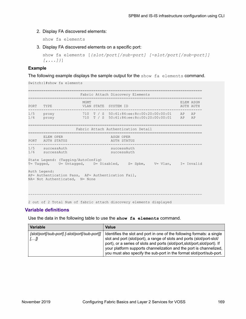
2. Display FA discovered elements:
show fa elements3. Display FA discovered elements on a specific port:
show fa elements [{slot/port[/sub-port] [-slot/port[/sub-port]][,...]}]
ExampleThe following example displays the sample output for the show fa elements command.Switch:1#show fa elements
================================================================================ Fabric Attach Discovery Elements================================================================================ MGMT ELEM ASGNPORT TYPE VLAN STATE SYSTEM ID AUTH AUTH--------------------------------------------------------------------------------1/5 proxy 710 T / S 50:61:84:ee:8c:00:20:00:00:01 AP AP1/6 proxy 710 T / S 50:61:84:ee:8c:00:20:00:00:01 AP AP
================================================================================ Fabric Attach Authentication Detail================================================================================ ELEM OPER ASGN OPERPORT AUTH STATUS AUTH STATUS--------------------------------------------------------------------------------1/5 successAuth successAuth1/6 successAuth successAuth
State Legend: (Tagging/AutoConfig)T= Tagged, U= Untagged, D= Disabled, S= Spbm, V= Vlan, I= Invalid
Auth Legend:AP= Authentication Pass, AF= Authentication Fail,NA= Not Authenticated, N= None
--------------------------------------------------------------------------------
2 out of 2 Total Num of fabric attach discovery elements displayed
Variable definitionsUse the data in the following table to use the show fa elements command.
Variable Value{slot/port[/sub-port] [-slot/port[/sub-port]][,...]}
Identifies the slot and port in one of the following formats: a singleslot and port (slot/port), a range of slots and ports (slot/port-slot/port), or a series of slots and ports (slot/port,slot/port,slot/port). Ifyour platform supports channelization and the port is channelized,you must also specify the sub-port in the format slot/port/sub-port.
SPBM and IS-IS infrastructure configuration using CLI
November 2019 Configuring Fabric Basics and Layer 2 Services for VOSS 169

Viewing Fabric Attach I-SID-to-VLAN AssignmentsUse this procedure to display the I-SID-to-VLAN assignments advertised by an FA Client or an FAProxy, to be supported on the FA Server. These assignments can be accepted or rejected by the FAServer. An assignment that is successfully accepted by the FA Server results in the creation of aSwitched UNI I-SID on the interface.
Before you beginVerify that IS-IS and SPBM are properly configured on the FA Server switch.
• Verify SPBM configuration using the command show running-config module spbm.
• Verify IS-IS configuration using one of the following commands:- show isis- show isis interface- show isis adjacency- show isis lsdb
Procedure1. Enter Privileged EXEC mode:
enable2. Display FA I-SID-to-VLAN assignments:
show fa assignment3. Display FA I-SID-to-VLAN assignments on specific ports:
show fa assignment [{slot/port[/sub-port] [-slot/port[/sub-port]][,...]}]
ExampleThe following example displays a sample output for the show fa assignment command.
Note:The state of I-SID-to-VLAN assignments on a client or proxy device is pending until it ischanged by the FA Server to active or reject.
Switch:>enSwitch:1#show fa assignment======================================================================= Fabric Attach Assignment Map=======================================================================Interface I-SID Vlan State Origin-----------------------------------------------------------------------1/1 2 2 active proxy1/2 3 3 active proxy1/2 4 4 active proxy1/3 5 5 reject proxy-----------------------------------------------------------------------
4 out of 4 Total Num of fabric attach assignment mappings displayed
SPBM and IS-IS infrastructure configuration
November 2019 Configuring Fabric Basics and Layer 2 Services for VOSS 170

-----------------------------------------------------------------------
Variable definitionsUse the data in the following table to use the show fa assignment command.
Variable Value{slot/port[/sub-port] [-slot/port[/sub-port]][,...]}
Identifies the slot and port in one of the following formats: a singleslot and port (slot/port), a range of slots and ports (slot/port-slot/port), or a series of slots and ports (slot/port,slot/port,slot/port). Ifyour platform supports channelization and the port is channelized,you must also specify the sub-port in the format slot/port/sub-port.
Viewing Fabric Attach StatisticsIf FA discovery fails, use this procedure to display FA statistics to determine if FA discovery TLVswere processed. You can also view the FA assignment statistics to determine the number of FAassignments that were accepted or rejected by the FA Server.
You can view the statistics at either the global level or at the port (interface) level.
Procedure1. Enter Privileged EXEC mode:
enable2. View global level FA statistics:
show fa statistics [summary]3. View FA statistics at the slot/port level:
show fa statistics [{slot/port[/sub-port] [-slot/port[/sub-port]][,...]}]
Note:
If a slot is removed from the switch chassis, the FA statistics are not displayed on theslot ports. When the slot is inserted back again, the statistics counters are reset.
4. (Optional) Clear FA statistics:
clear fa statistics [summary] [{slot/port[/sub-port] [-slot/port[/sub-port]] [,...]}]
ExamplesViewing FA discovery and assignment statistics:Switch:1>enSwitch:1#show fa statistics ========================================================================== Fabric Attach STATISTICS==========================================================================Port DiscElem DiscElem DiscElem DiscAuth
SPBM and IS-IS infrastructure configuration using CLI
November 2019 Configuring Fabric Basics and Layer 2 Services for VOSS 171

Received Expired Deleted Failed--------------------------------------------------------------------------1/1 3057 0 1 01/2 2000 0 1 0
=========================================================================== Fabric Attach ASSIGNMENTS STATISTICS===========================================================================Port Asgn Asgn Asgn Asgn Asgn AsgnAuth Received Accepted Rejected Expired Deleted Failed---------------------------------------------------------------------------1/1 3149 3 1 3 0 01/2 1500 0 1 2 0 0
View a summary of the FA discovery and assignment statistics:Switch:1#show fa statistics summary
========================================================================== Fabric Attach STATISTICS SUMMARY==========================================================================Port DiscElem DiscElem DiscElem DiscAuth Received Expired Deleted Failed--------------------------------------------------------------------------1/1 3057 0 1 01/2 2000 0 1 0
=========================================================================== Fabric Attach ASSIGNMENTS STATISTICS SUMMARY===========================================================================Port Asgn Asgn Asgn Asgn Asgn AsgnAuth Received Accepted Rejected Expired Deleted Failed---------------------------------------------------------------------------1/1 3149 3 1 3 0 01/2 1500 0 1 2 0 0
Viewing FA statistics on a specific port (port 1/1):Switch:1>enSwitch:1#show fa statistics 1/1
========================================================================== Fabric Attach STATISTICS==========================================================================Port DiscElem DiscElem DiscElem DiscAuth Received Expired Deleted Failed--------------------------------------------------------------------------1/1 3057 0 1 0
========================================================================== Fabric Attach ASSIGNMENTS STATISTICS==========================================================================Port Asgn Asgn Asgn Asgn Asgn AsgnAuth Received Accepted Rejected Expired Deleted Failed--------------------------------------------------------------------------1/1 3149 3 1 3 0 0
Optionally, clear FA statistics and verify that the statistics are cleared.Switch:1#clear fa statisticsSwitch:1#show fa statistics
==========================================================================
SPBM and IS-IS infrastructure configuration
November 2019 Configuring Fabric Basics and Layer 2 Services for VOSS 172

Fabric Attach STATISTICS==========================================================================Port DiscElem DiscElem DiscElem DiscAuth Received Expired Deleted Failed--------------------------------------------------------------------------1/1 0 0 0 01/2 0 0 0 0
========================================================================== Fabric Attach ASSIGNMENTS STATISTICS==========================================================================Port Asgn Asgn Asgn Asgn Asgn AsgnAuth Received Accepted Rejected Expired Deleted Failed--------------------------------------------------------------------------1/1 0 0 0 0 0 01/2 0 0 0 0 0 0
Variable DefinitionsUse the data in the following table to use the show fa statistics command.
Variable Valuesummary Displays a summary of Fabric Attach element discovery and
assignment statistics at the global level.{slot/port[/sub-port] [-slot/port[/sub-port]][,...]}
Identifies the slot and port in one of the following formats: a singleslot and port (slot/port), a range of slots and ports (slot/port-slot/port), or a series of slots and ports (slot/port,slot/port,slot/port). Ifyour platform supports channelization and the port is channelized,you must also specify the sub-port in the format slot/port/sub-port.
Configuring global LLDP transmission parametersBefore you begin
• In the GigabitEthernet Interface Configuration mode, specify the LLDP port status as transmitonly or transmit and receive.
About this taskUse this procedure to configure global LLDP transmission parameters on the switch. If required, youcan also restore these parameters to their default values.
Procedure1. Enter GigabitEthernet Interface Configuration mode:
enableconfigure terminalinterface GigabitEthernet {slot/port[/sub-port][-slot/port[/sub-port]][,...]}
Note:
If your platform supports channelization and the port is channelized, you must alsospecify the sub-port in the format slot/port/sub-port.
SPBM and IS-IS infrastructure configuration using CLI
November 2019 Configuring Fabric Basics and Layer 2 Services for VOSS 173

2. To configure the LLDP transmission parameters, enter:
lldp [tx-interval|tx-hold-multiplier]3. (Optional) To restore specific LLDP transmission parameters to their default values, enter:
default lldp [tx-interval|tx-hold-multiplier]4. (Optional) To restore all LLDP transmission parameters to their default values, enter:
default lldpExampleConfigure the LLDP transmission interval. The LLDP port status is set to transmit and receive priorto the configuration.Switch:1>enableSwitch:1#configure terminalSwitch:1(config)#interface GigabitEthernet 4/4Switch:1(config-if)#lldp status txAndRxSwitch:1(config-if)#exitSwitch:1(config)#lldp tx-interval 31
Optionally, restore the LLDP transmission interval to its default value:Switch:1>enableSwitch:1#configure terminalSwitch:1(config)#default lldp tx-interval
Variable definitionsUse the information in the following table to help you understand the lldp command.
Variable Valuetx-interval<5–32768> Specifies the global LLDP transmit interval in
seconds, that is, the interval in which LLDP framesare transmitted.
The default is 30 seconds.tx-hold-multiplier <2–10> Configures the multiplier for the transmit interval
used to compute the Time To Live (TTL) value inLLDP frames.
The default is 4 seconds.
Viewing global LLDP statisticsUse this procedure to view and verify global LLDP statistics.
Procedure1. Enter Privileged EXEC mode:
enable2. To view LLDP statistics, enter:
show lldp stats
SPBM and IS-IS infrastructure configuration
November 2019 Configuring Fabric Basics and Layer 2 Services for VOSS 174

3. To view LLDP reception statistics, enter:
show lldp rx-stats4. To view LLDP transmission statistics, enter:
show lldp tx-stats5. (Optional) Clear global LLDP statistics:
clear lldp stats summaryExampleView LLDP statistics:Switch:1>enableSwitch:1#show lldp stats
================================================================= LLDP Stats=================================================================Inserts Deletes Drops Ageouts-----------------------------------------------------------------0 0 0 0-----------------------------------------------------------------
View LLDP transmission statistics:Switch:1#show lldp tx-stats================================================================ LLDP Tx-Stats================================================================
PORT NUM FRAMES----------------------------------------------------------------1/2 100
View LLDP reception statistics:Switch:1#show lldp rx-stats
================================================================ LLDP Rx-Stats=================================================================
Port Frames Frames Frames TLVs TLVs AgeOutsNum Discarded Errors Total Discarded Unrecognized------------------------------------------------------------------1/2 0 0 46 0 0 0
Viewing Port-based LLDP StatisticsUse this procedure to verify port-based LLDP statistics.
About this taskLLDP operates at the interface level. Enabling FA on a port automatically enables LLDPtransmission and reception on the port. It also enables traffic tagging and disables spanning tree onthat port.Enabling FA on an MLT enables LLDP transmission and reception on all ports in the MLT.
SPBM and IS-IS infrastructure configuration using CLI
November 2019 Configuring Fabric Basics and Layer 2 Services for VOSS 175

Note:When FA is enabled on ports in an MLT or LACP MLT, tagging is enabled and spanning tree isdisabled on those ports.When a port is removed from an MLT, LLDP transmission on that port stops and spanning treeis enabled. Any I-SID-to-VLAN mappings on that port are removed, if not already learned on anyother port in the MLT. This also causes the Switched UNI I-SID to be deleted from the MLT. Ifhowever, the mappings are learned on another port on the MLT, then the Switched UNI I-SIDcontinues to exist for that MLT.
Procedure1. Enter Privileged EXEC mode:
enable2. To verify successful LLDP transmission on a port, enter:
show lldp tx-stats port {slot/port[/sub-port] [-slot/port[/sub-port]] [,...]}
3. To verify that a port receives LLDP PDUs successfully, enter:
show lldp rx-stats port {slot/port[/sub-port] [-slot/port[/sub-port]] [,...]}
4. (Optional) To clear LLDP statistics on a port, or ports, enter:
clear lldp stats {slot/port[/sub-port] [-slot/port[/sub-port]][,...]}
ExampleVerify LLDP transmission statistics on a port:Switch:1>enSwitch:1#show lldp tx-stats port 1/2================================================================ LLDP Tx-Stats================================================================
PORT NUM FRAMES----------------------------------------------------------------1/2 100
Verify that the port is receiving LLDP PDUs:Switch:1#show lldp rx-stats port 1/2
================================================================================ LLDP Rx-Stats================================================================================
Port Frames Frames Frames TLVs TLVs AgeOutsNum Discarded Errors Total Discarded Unsupported (Non FA) (Non FA)--------------------------------------------------------------------------------1/2 0 0 46 0 0 0
SPBM and IS-IS infrastructure configuration
November 2019 Configuring Fabric Basics and Layer 2 Services for VOSS 176

Variable DefinitionsUse the data in the following table to use the show lldp tx-stats and the show lldp rx-stats commands.
Variable Value{slot/port[/sub-port] [-slot/port[/sub-port]] [,...]} Identifies the slot and port in one of the following
formats: a single slot and port (slot/port), a range ofslots and ports (slot/port-slot/port), or a series ofslots and ports (slot/port,slot/port,slot/port). If yourplatform supports channelization and the port ischannelized, you must also specify the sub-port inthe format slot/port/sub-port.
Displaying Learned LLDP NeighborsUse this procedure to verify details of the LLDP neighbors learned.
Procedure1. Enter Privileged EXEC mode:
enable2. Verify details of LLDP neighbors learned:
show lldp neighbor3. Verify details of LLDP neighbors learned on a specific port:
show lldp neighbor port {slot/port[/sub-port] [-slot/port[/sub-port]] [,...]}
ExampleThe following example shows how two switches—an FA Server and an FA Proxy discover eachother as LLDP neighbors. Switch A, which is the FA Server is an VSP 7200 Series switch (model7254XSQ) and switch B which is the proxy device is an ERS 4826GTS switch.The following examples shows neighbor discovery on non-channelized and channelized ports (ifyour platform supports channelization).On the non-channelized port 1/1 on the FA Server, verify neighbor discovery of the proxy switch.SwitchA:1>enSwitchA:1#show lldp neighbor
========================================================================================== LLDP Neighbor==========================================================================================
Port: 1/1 Index : 1 Time: 1 day(s), 04:03:52 ChassisId: MAC Address 70:30:18:5a:05:00 PortId : MAC Address 70:30:18:5a:05:07 SysName : SysCap : Br / Br PortDescr: Port 7 SysDescr : Ethernet Routing Switch 4826GTS HW:10 FW:5.8.0.1 SW:v6.9.2.027
SPBM and IS-IS infrastructure configuration using CLI
November 2019 Configuring Fabric Basics and Layer 2 Services for VOSS 177
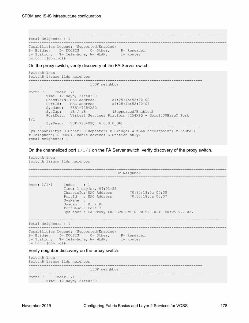
------------------------------------------------------------------------------------------Total Neighbors : 1------------------------------------------------------------------------------------------Capabilities Legend: (Supported/Enabled)B= Bridge, D= DOCSIS, O= Other, R= Repeater,S= Station, T= Telephone, W= WLAN, r= RouterSwitch:1(config)#
On the proxy switch, verify discovery of the FA Server switch.SwitchB:1>enSwitchB:1#show lldp neighbor------------------------------------------------------------------------------- LLDP neighbor -------------------------------------------------------------------------------Port: 7 Index: 71 Time: 12 days, 21:40:30 ChassisId: MAC address a4:25:1b:52:70:00 PortId: MAC address a4:25:1b:52:70:04 SysName: BEB1-7254XSQ SysCap: rB / rB (Supported/Enabled) PortDesc: Virtual Services Platform 7254XSQ - Gbic1000BaseT Port1/1 SysDescr: VSP-7254XSQ (6.0.0.0_GA) -------------------------------------------------------------------------------Sys capability: O-Other; R-Repeater; B-Bridge; W-WLAN accesspoint; r-Router;T-Telephone; D-DOCSIS cable device; S-Station only.Total neighbors: 1
On the channelized port 1/1/1 on the FA Server switch, verify discovery of the proxy switch.SwitchA:1>enSwitchA:1#show lldp neighbor
========================================================================================== LLDP Neighbor==========================================================================================
Port: 1/1/1 Index : 1 Time: 1 day(s), 04:03:52 ChassisId: MAC Address 70:30:18:5a:05:00 PortId : MAC Address 70:30:18:5a:05:07 SysName : SysCap : Br / Br PortDescr: Port 7 SysDescr : FA Proxy 4826GTS HW:10 FW:5.8.0.1 SW:v5.9.2.027
------------------------------------------------------------------------------------------Total Neighbors : 1------------------------------------------------------------------------------------------Capabilities Legend: (Supported/Enabled)B= Bridge, D= DOCSIS, O= Other, R= Repeater,S= Station, T= Telephone, W= WLAN, r= RouterSwitch:1(config)#
Verify neighbor discovery on the proxy switch.SwitchB:1>enSwitchB:1#show lldp neighbor------------------------------------------------------------------------------- LLDP neighbor -------------------------------------------------------------------------------Port: 7 Index: 71 Time: 12 days, 21:40:30
SPBM and IS-IS infrastructure configuration
November 2019 Configuring Fabric Basics and Layer 2 Services for VOSS 178
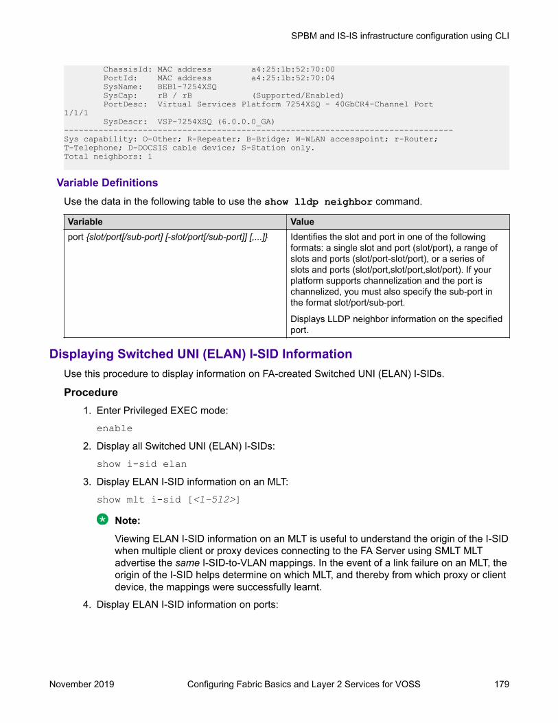
ChassisId: MAC address a4:25:1b:52:70:00 PortId: MAC address a4:25:1b:52:70:04 SysName: BEB1-7254XSQ SysCap: rB / rB (Supported/Enabled) PortDesc: Virtual Services Platform 7254XSQ - 40GbCR4-Channel Port1/1/1 SysDescr: VSP-7254XSQ (6.0.0.0_GA) -------------------------------------------------------------------------------Sys capability: O-Other; R-Repeater; B-Bridge; W-WLAN accesspoint; r-Router;T-Telephone; D-DOCSIS cable device; S-Station only.Total neighbors: 1
Variable DefinitionsUse the data in the following table to use the show lldp neighbor command.
Variable Valueport {slot/port[/sub-port] [-slot/port[/sub-port]] [,...]} Identifies the slot and port in one of the following
formats: a single slot and port (slot/port), a range ofslots and ports (slot/port-slot/port), or a series ofslots and ports (slot/port,slot/port,slot/port). If yourplatform supports channelization and the port ischannelized, you must also specify the sub-port inthe format slot/port/sub-port.
Displays LLDP neighbor information on the specifiedport.
Displaying Switched UNI (ELAN) I-SID InformationUse this procedure to display information on FA-created Switched UNI (ELAN) I-SIDs.
Procedure1. Enter Privileged EXEC mode:
enable2. Display all Switched UNI (ELAN) I-SIDs:
show i-sid elan3. Display ELAN I-SID information on an MLT:
show mlt i-sid [<1–512>]
Note:
Viewing ELAN I-SID information on an MLT is useful to understand the origin of the I-SIDwhen multiple client or proxy devices connecting to the FA Server using SMLT MLTadvertise the same I-SID-to-VLAN mappings. In the event of a link failure on an MLT, theorigin of the I-SID helps determine on which MLT, and thereby from which proxy or clientdevice, the mappings were successfully learnt.
4. Display ELAN I-SID information on ports:
SPBM and IS-IS infrastructure configuration using CLI
November 2019 Configuring Fabric Basics and Layer 2 Services for VOSS 179

show interfaces gigabitEthernet i-sid [{slot/port[/sub-port] [-slot/port[/sub-port]] [,...]}]
ExampleDisplay information on all Switched UNI (ELAN) I-SIDs.The following sample output displays, for example, the I-SID information on one of the peer switchesof the FA Server, in a dual-homed SMLT configuration.Switch:1>enSwitch:1#show i-sid elan
========================================================================================== Isid Info==========================================================================================ISID ISID PORT MLT ORIGINID TYPE VLANID INTERFACES INTERFACES------------------------------------------------------------------------------------------2002 ELAN N/A c2002:1/10 - DISC_LOCAL4000 ELAN N/A - c4000:1 DISC_BOTH4001 ELAN N/A - c4001:1 DISC_LOCAL4030 ELAN N/A - c4030:1 DISC_BOTH4051 ELAN N/A - c4051:1 DISC_BOTH10200 ELAN N/A - c200:1 DISC_REMOTE
c: customer vid u: untagged-traffic
All 6 out of 6 Total Num of Elan i-sids displayed
Note:The I-SID TYPE field displays once for each I-SID. The I-SID TYPE of an I-SID that is eitherlearned through FA mapping assignments or configured as an FA management I-SID, is alwaysELAN. If a platform VLAN has the same I-SID value as that of the I-SID in an FA mappingassignment or in an FA management I-SID configuration, then the platform VLAN is associatedwith the I-SID endpoint and appears in the VLANID column.
Note:• The ORIGIN field displays once for each I-SID. It indicates the origin of the I-SID and not
the origin of the I-SID endpoint. To view the origin of the I-SID endpoints, execute either theshow mlt i-sid or the show interfaces gigabitEthernet i-sid command.
- The origin of I-SID 4000 displays as DISC_BOTH, because it is discovered on both vISTpeers.
- The origin of I-SID 4001 displays as DISC_LOCAL because it is first discovered on thelocal FA Server switch.
- The origin of I-SID 10200 displays as DISC_REMOTE because it is first discovered onthe peer switch and then synchronized with the local switch.
• If the origin of an I-SID is DISC_LOCAL, DISC_REMOTE, DISC_BOTH orMANAGEMENT, it changes to CONFIG, after you manually configure an endpoint on the I-SID.
Display MLT I-SID information for MLT 1.
SPBM and IS-IS infrastructure configuration
November 2019 Configuring Fabric Basics and Layer 2 Services for VOSS 180

In this sample output, the ORIGIN field indicates the origin of the I-SID endpoint.Switch:1#show mlt i-sid 1
================================================================================ MLT Isid Info================================================================================ ISID ISIDMLTID IFINDEX ID VLANID C-VID TYPE ORIGIN BPDU--------------------------------------------------------------------------------1 6144 4000 N/A 4000 ELAN DISC_BOTH1 6144 4001 N/A 4001 ELAN DISC_LOCAL1 6144 4030 N/A 4030 ELAN DISC_BOTH1 6144 4051 N/A 4051 ELAN DISC_BOTH1 6144 10200 N/A 200 ELAN DISC_REMOTE--------------------------------------------------------------------------------
5 out of 6 Total Num of i-sid endpoints displayed
Display I-SID information on the port 1/10:
In this sample output, the ORIGIN field indicates the origin of the I-SID endpoint.Switch:1#show interfaces gigabitEthernet i-sid 1/10
================================================================================ PORT Isid Info================================================================================ ISID ISIDPORTNUM IFINDEX ID VLANID C-VID TYPE ORIGIN BPDU--------------------------------------------------------------------------------1/10 201 2002 N/A 601 ELAN DISC_LOCAL--------------------------------------------------------------------------------
1 out of 6 Total Num of i-sid endpoints displayed
Variable DefinitionsUse the data in the following table to use the show i-sid command.
Variable Valueelan Displays all ELAN I-SIDs.
Use the data in the following table to use the show mlt i-sid command.
Variable Value<1–512> The valid range for MLT ID.
Use the data in the following table to use the show interfaces gigabitEthernet i-sidcommand.
Variable Value{slot/port[/sub-port] [-slot/port[/sub-port]] [,...]}
Identifies the slot and port in one of the following formats: a single slotand port (slot/port), a range of slots and ports (slot/port-slot/port), or aseries of slots and ports (slot/port,slot/port,slot/port). If your platformsupports channelization and the port is channelized, you must alsospecify the sub-port in the format slot/port/sub-port.
SPBM and IS-IS infrastructure configuration using CLI
November 2019 Configuring Fabric Basics and Layer 2 Services for VOSS 181

Enabling or disabling FA Zero Touch Client AttachmentUse this procedure to enable or disable the global FA Zero Touch Client Attachment feature on anFA Proxy or Server. By default, FA Zero Touch Client Attachment support is enabled.
Procedure1. Enter Global Configuration mode:
enableconfigure terminal
2. Enable an FA Zero Touch client:
fa zero-touch-client standard <camera|ona-sdn|ona-spb-over-ip|phone|router|security-device|srvr-endpt|switch|video|virtual-switch|wap-type1|wap-type2> i-sid <1–15999999>
3. Disable an FA Zero Touch client:
no fa zero-touch-client standard <camera|ona-sdn|ona-spb-over-ip|phone|router|security-device|srvr-endpt|switch|video|virtual-switch|wap-type1|wap-type2>
ExampleSwitch:1(config)# fa zero-touch-client standard camera i-sid 1003Switch:1(config)# no fa zero-touch-client standard camera
Variable definitionsUse the data in the following table to use the fa zero-touch-client standard command.
Variable Valuecamera Specify element type to match camera.ona-sdn Specify element type to match ona-sdn.ona-spb-over-ip Specify element type to match ona-spb-over-ip.phone Specify element type to match phone.router Specify element type to match router.security-device Specify element type to match security-device.srvr-endpt Specify element type to match srvr-endpt.switch Specify element type to match switch.video Specify element type to match video.virtual-switch Specify element type to match virtual-switch.wap-type1 Specify element type to match wap-type1.wap-type2 Specify element type to match wap-type2.
SPBM and IS-IS infrastructure configuration
November 2019 Configuring Fabric Basics and Layer 2 Services for VOSS 182

Displaying FA Zero Touch Client AttachmentUse this procedure to display the Zero Touch Client Attachment data you have configured on an FAServer.
Procedure1. Enter Privileged EXEC mode:
enable2. Display Zero Touch Client Attachment data:
show fa zero-touch-clientExampleThe following example displays sample output for the show fa zero-touch-client command.Switch:1#show fa zero-touch-client
================================================================================
Fabric Attach Zero Touch Client================================================================================
Type Description I-SID VLAN--------------------------------------------------------------------------------6 wap-type1 11111 12311 camera 2000 20017 ona-spb-over-ip 40001 4001--------------------------------------------------------------------------------
3 out of 3 Total Num of Fabric Attach Zero Touch Client entries displayed--------------------------------------------------------------------------------
Configure Endpoint Tracking Using CLINote:
DEMO FEATURE - Endpoint Tracking is a demonstration feature. Demonstration features areprovided for testing purposes. Demonstration features are for lab use only and are not for use ina production environment.
The following sections provide procedural information you can use to configure Endpoint Trackingusing CLI.
Configure Endpoint Tracking InterfacesNote:
DEMO FEATURE - Endpoint Tracking is a demonstration feature. Demonstration features areprovided for testing purposes. Demonstration features are for lab use only and are not for use ina production environment.
SPBM and IS-IS infrastructure configuration using CLI
November 2019 Configuring Fabric Basics and Layer 2 Services for VOSS 183

Create and enable Endpoint Tracking on ports and MLT/SMLT interfaces. Creating, deleting,enabling, and disabling Endpoint Tracking on interfaces can be accomplished as separate stepsusing this procedure.
Before you begin• In Extreme Management Center, configure your third-party virtualization platform, and the
RADIUS server used for Endpoint Tracking authentication. For information about configuringExtreme Management Center, see the Extreme Management Center documentation at https://www.extremenetworks.com/support/documentation/.
• On the switch, add and configure the RADIUS server as configured in Extreme ManagementCenter. For information about adding a RADIUS server on the switch and configuring it forEndpoint Tracking, see Configuring Security for VOSS.
About this taskConfigure ports and MLT/SMLT interfaces to function as Switched UNI interfaces, and then createand enable Endpoint Tracking on those interfaces.
Procedure1. Enter Interface Configuration mode:
enableconfigure terminalinterface GigabitEthernet {slot/port[/sub-port][-slot/port[/sub-port]][,...]} or interface mlt <1-512>
Note:
If your platform supports channelization and the port is channelized, you must alsospecify the sub-port in the format slot/port/sub-port.
2. Enable Flex UNI on the interface:
flex-uni enable3. Create, or create and enable Endpoint Tracking:
• Create Endpoint Tracking on the interface:
endpoint-tracking• Create and enable Endpoint Tracking on the interface:
endpoint-tracking enableNext stepsConfigure Endpoint Tracking globally on the switch.
SPBM and IS-IS infrastructure configuration
November 2019 Configuring Fabric Basics and Layer 2 Services for VOSS 184
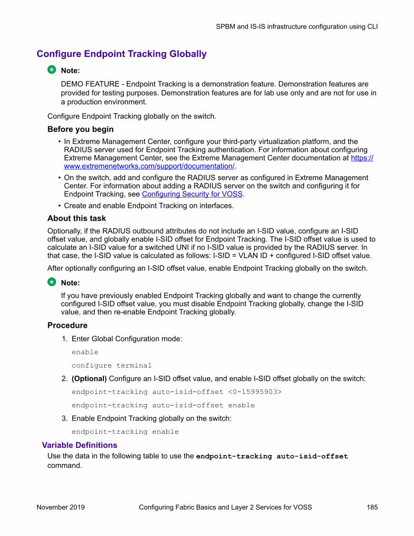
Configure Endpoint Tracking GloballyNote:
DEMO FEATURE - Endpoint Tracking is a demonstration feature. Demonstration features areprovided for testing purposes. Demonstration features are for lab use only and are not for use ina production environment.
Configure Endpoint Tracking globally on the switch.
Before you begin• In Extreme Management Center, configure your third-party virtualization platform, and the
RADIUS server used for Endpoint Tracking authentication. For information about configuringExtreme Management Center, see the Extreme Management Center documentation at https://www.extremenetworks.com/support/documentation/.
• On the switch, add and configure the RADIUS server as configured in Extreme ManagementCenter. For information about adding a RADIUS server on the switch and configuring it forEndpoint Tracking, see Configuring Security for VOSS.
• Create and enable Endpoint Tracking on interfaces.
About this taskOptionally, if the RADIUS outbound attributes do not include an I-SID value, configure an I-SIDoffset value, and globally enable I-SID offset for Endpoint Tracking. The I-SID offset value is used tocalculate an I-SID value for a switched UNI if no I-SID value is provided by the RADIUS server. Inthat case, the I-SID value is calculated as follows: I-SID = VLAN ID + configured I-SID offset value.After optionally configuring an I-SID offset value, enable Endpoint Tracking globally on the switch.
Note:If you have previously enabled Endpoint Tracking globally and want to change the currentlyconfigured I-SID offset value, you must disable Endpoint Tracking globally, change the I-SIDvalue, and then re-enable Endpoint Tracking globally.
Procedure1. Enter Global Configuration mode:
enableconfigure terminal
2. (Optional) Configure an I-SID offset value, and enable I-SID offset globally on the switch:
endpoint-tracking auto-isid-offset <0-15995903>endpoint-tracking auto-isid-offset enable
3. Enable Endpoint Tracking globally on the switch:
endpoint-tracking enableVariable Definitions
Use the data in the following table to use the endpoint-tracking auto-isid-offsetcommand.
SPBM and IS-IS infrastructure configuration using CLI
November 2019 Configuring Fabric Basics and Layer 2 Services for VOSS 185
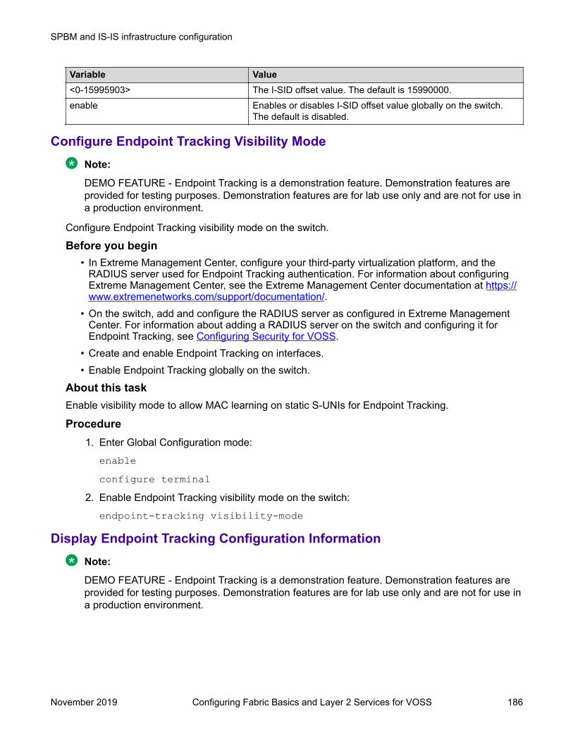
Variable Value<0-15995903> The I-SID offset value. The default is 15990000.enable Enables or disables I-SID offset value globally on the switch.
The default is disabled.
Configure Endpoint Tracking Visibility ModeNote:
DEMO FEATURE - Endpoint Tracking is a demonstration feature. Demonstration features areprovided for testing purposes. Demonstration features are for lab use only and are not for use ina production environment.
Configure Endpoint Tracking visibility mode on the switch.
Before you begin• In Extreme Management Center, configure your third-party virtualization platform, and the
RADIUS server used for Endpoint Tracking authentication. For information about configuringExtreme Management Center, see the Extreme Management Center documentation at https://www.extremenetworks.com/support/documentation/.
• On the switch, add and configure the RADIUS server as configured in Extreme ManagementCenter. For information about adding a RADIUS server on the switch and configuring it forEndpoint Tracking, see Configuring Security for VOSS.
• Create and enable Endpoint Tracking on interfaces.• Enable Endpoint Tracking globally on the switch.
About this taskEnable visibility mode to allow MAC learning on static S-UNIs for Endpoint Tracking.
Procedure1. Enter Global Configuration mode:
enableconfigure terminal
2. Enable Endpoint Tracking visibility mode on the switch:
endpoint-tracking visibility-mode
Display Endpoint Tracking Configuration InformationNote:
DEMO FEATURE - Endpoint Tracking is a demonstration feature. Demonstration features areprovided for testing purposes. Demonstration features are for lab use only and are not for use ina production environment.
SPBM and IS-IS infrastructure configuration
November 2019 Configuring Fabric Basics and Layer 2 Services for VOSS 186

Perform this procedure to display configuration information for Endpoint Tracking.
About this taskPerform this procedure to display global, interface and binding information for Endpoint Tracking.
Procedure1. To enter User EXEC mode, log on to the switch.
2. Display the global status of Endpoint Tracking on the switch, and the configured I-SID offsetvalue, if applicable:
show endpoint-tracking3. Display the status of all interfaces that have Endpoint Tracking created:
show endpoint-tracking interfaces [gigabitEthernet {slot/port[/sub-port][-slot/port[/sub-port]][,...]}] | [mlt <1-512>]]
4. Display the VLAN:I-SID binding information for the switch, for ports, or for MLT/SMLTinterfaces:
show endpoint-tracking bindings [gigabitEthernet {slot/port[/sub-port][-slot/port[/sub-port]][,...]}] | [mlt <1-512>]]
ExampleThe following example displays all of the Endpoint Tracking configuration information for a switch.Switch:1>show endpoint-tracking======================================================================================= Endpoint Tracking Configuration=======================================================================================
endpoint tracking status : ENABLED auto-isid-offset value : 15990000 auto-isid-offset enabled : ENABLED visibility-mode status : ENABLED Switch:1>show endpoint-tracking interfaces========================================================================================== Endpoint Tracking Interfaces ==========================================================================================PORT NUM INDEX STATUS------------------------------------------------------------------------------------------ 1/1 192 Enabled1/10 201 EnabledMLT-2 6145 EnabledMLT-5 6148 Disabled-------------------------------------------------------------------------------- 4 out of 4 Total Num of Endpoint Tracking interfaces displayed --------------------------------------------------------------------------------Switch:1>show endpoint-tracking bindings ================================================================================================================== Endpoint Tracking Bindings==================================================================================================================PORT/MLT INDEX MAC STATUS VLAN ID ISID SOURCE TIMEOUT TIME REMAINING ------------------------------------------------------------------------------------------------------------------1/10 201 00:00:00:00:1b:01 accept 27 15990027 autoconfig 0 day(s), 00:01:40 0 day(s), 00:00:001/10 201 00:00:00:00:1b:02 accept 27 15990027 autoconfig 0 day(s), 00:01:40 0 day(s), 00:00:001/10 201 00:00:00:00:1b:03 accept 27 15990027 autoconfig 0 day(s), 00:01:40 0 day(s), 00:00:00
SPBM and IS-IS infrastructure configuration using CLI
November 2019 Configuring Fabric Basics and Layer 2 Services for VOSS 187

1/10 201 00:00:00:00:1b:04 accept 27 15990027 autoconfig 0 day(s), 00:01:40 0 day(s), 00:00:001/10 201 00:00:00:00:1b:05 accept 27 15990027 autoconfig 0 day(s), 00:01:40 0 day(s), 00:00:00 5 out of 5 Total Num of Endpoint Tracking bindings displayed.
Variable DefinitionsUse the data in the following table to use the show endpoint-tracking bindings command.
Variable ValuegigabitEthernet {slot/port[/sub-port] [-slot/port[/sub-port]] [,...]}
Identifies the slot and port in one of the following formats: a single slot andport (slot/port), a range of slots and ports (slot/port-slot/port), or a series ofslots and ports (slot/port,slot/port,slot/port). If your platform supportschannelization and the port is channelized, you must also specify the sub-port in the format slot/port/sub-port.
MLT <1-512> Specifies the MLT ID.
IS-IS external metric configuration using the CLIThis section provides procedures for IS-IS external metric configuration.
Matching metric type for IS-IS routesAbout this taskUse this procedure to match the external metric-type by using a route-map for any of the followingcases:
• accepting a remote IS-IS route with the help of IS-IS accept policies.• redistributing IS-IS routes into other protocols.
Before you begin• You must configure the required SPBM and IS-IS infrastructure.• You must log on to the route-map configuration mode in the CLI.
Procedure1. Enter Route-Map Configuration mode:
enableconfigure terminalroute-map WORD<1-64> <1-65535>
2. Match IS-IS metric type:
match metric-type-isis {any|internal|external}3. Permit the route policy action:
permit4. Enable the route policy
enable
SPBM and IS-IS infrastructure configuration
November 2019 Configuring Fabric Basics and Layer 2 Services for VOSS 188

ExampleMatch metric type for IS-IS routes:Switch:1> enableSwitch:1# configure terminalSwitch:1(config)# route-map ro1 10Switch:1(route-map)# match metric-type-isis internalSwitch:1(route-map)# permitSwitch:1(route-map)# enable
Match metric type for IS-IS routes in accept policies:Switch:1> enableSwitch:1# configure terminalSwitch:1(config)# route-map ro1 10Switch:1(route-map)# match metric-type-isis internalSwitch:1(route-map)# permitSwitch:1(route-map)# enableSwitch:1(route-map)# exitSwitch:1(config)# router isisSwitch:1(config-isis)# accept route-map ro1Switch:1(config-isis)# exitSwitch:1(config)# isis apply accept
Match metric type to redistribute IS-IS routes into some other protocol (OSPF,RIP,BGP)Switch:1> enableSwitch:1# configure terminalSwitch:1(config)# route-map ro1 10Switch:1(route-map)# match metric-type-isis internalSwitch:1(route-map)# permitSwitch:1(route-map)# enableSwitch:1(route-map)# exitSwitch:1(config)# router bgpSwitch:1(router-bgp)# redistribute isis route-map ro1Switch:1(router-bgp)# exitSwitch:1(config)# ip bgp apply redistribute
Variable definitionsUse the data in the following table to use the match metric-type-isis command.
Variable Valuemetric-type-isis {any|internal|external} Specifies the IS-IS metric type.
• internal – permits or denies routes that are internalto the IS-IS domain.
• external – permits or denies routes that originatefrom an external routing protocol domain.
• any – permits or denies both internal routes as wellas external routes.
Setting metric type for IS-IS routesAbout this taskUse this procedure to set the IS-IS external metric-type by using a route-map for any of the followingcases:
• accepting a remote IS-IS route with the help of IS-IS accept policies.
SPBM and IS-IS infrastructure configuration using CLI
November 2019 Configuring Fabric Basics and Layer 2 Services for VOSS 189
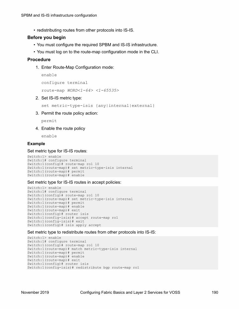
• redistributing routes from other protocols into IS-IS.
Before you begin• You must configure the required SPBM and IS-IS infrastructure.• You must log on to the route-map configuration mode in the CLI.
Procedure1. Enter Route-Map Configuration mode:
enableconfigure terminalroute-map WORD<1-64> <1-65535>
2. Set IS-IS metric type:
set metric-type-isis {any|internal|external}3. Permit the route policy action:
permit4. Enable the route policy
enableExampleSet metric type for IS-IS routes:Switch:1> enableSwitch:1# configure terminalSwitch:1(config)# route-map ro1 10Switch:1(route-map)# set metric-type-isis internalSwitch:1(route-map)# permitSwitch:1(route-map)# enable
Set metric type for IS-IS routes in accept policies:Switch:1> enableSwitch:1# configure terminalSwitch:1(config)# route-map ro1 10Switch:1(route-map)# set metric-type-isis internalSwitch:1(route-map)# permitSwitch:1(route-map)# enableSwitch:1(route-map)# exitSwitch:1(config)# router isisSwitch:1(config-isis)# accept route-map ro1Switch:1(config-isis)# exitSwitch:1(config)# isis apply accept
Set metric type to redistribute routes from other protocols into IS-IS:Switch:1> enableSwitch:1# configure terminalSwitch:1(config)# route-map ro1 10Switch:1(route-map)# match metric-type-isis internalSwitch:1(route-map)# permitSwitch:1(route-map)# enableSwitch:1(route-map)# exitSwitch:1(config)# router isisSwitch:1(config-isis)# redistribute bgp route-map ro1
SPBM and IS-IS infrastructure configuration
November 2019 Configuring Fabric Basics and Layer 2 Services for VOSS 190

Switch:1(config-isis)# exitSwitch:1(config)# isis apply redistribute
Variable definitionsUse the data in the following table to use the set metric-type-isis command.
Variable Valuemetric-type-isis {any|internal|external} Specifies the IS-IS metric type.
• internal – permits or denies routes that are internalto the IS-IS domain.
• external – permits or denies routes that originatefrom an external routing protocol domain.
• any – permits or denies both internal routes as wellas external routes.
Setting metric type for IS-IS routes using global redistribute commandAbout this taskUse this procedure to set the IS-IS external metric-type using the global redistribute command forthe following cases redistributing routes from other protocols into IS-IS.
Before you begin• You must configure the required SPBM and IS-IS infrastructure.• You must log on to the IS-IS router configuration mode in the CLI.
Procedure1. Enter IS-IS Router Configuration mode:
enableconfigure terminalrouter isis
2. Set IS-IS metric type using global redistribute command:
redistribute direct metric-type {internal|external}3. Enable the route policy
redistribute direct enableExampleSet metric type for IS-IS routes using global redistribute command:Switch:1> enableSwitch:1# configure terminalSwitch:1(config)# router isisSwitch:1(config-isis)# redistribute direct metric-type internalSwitch:1(config-isis)# redistribute direct enable
SPBM and IS-IS infrastructure configuration using CLI
November 2019 Configuring Fabric Basics and Layer 2 Services for VOSS 191

Variable definitionsUse the data in the following table to use the redistribute direct metric-type command.
Variable Valuemetric-type {internal|external} Specifies the IS-IS metric type.
• internal – permits or denies routes that are internalto the IS-IS domain.
• external – permits or denies routes that originatefrom an external routing protocol domain.
Suspending duplicate system ID detection when replacing aswitch
When a switch is replaced and the original system ID and nickname is used, you must wait up to 20minutes for the LSPs with the original system to age out. This is due to duplicate system ID andnickname detection. However, you can suspend duplicate detection on the replacement switch sothat you can bring the switch into the network immediately.
About this taskTo temporarily disable duplicate detection on the replacement switch, perform the following steps inorder:
Procedure1. Copy the configuration file of the original switch to the replacement switch.
2. Power up the replacement switch while it is not connected to the SPB network, that is, NNIports are not connected.
3. Disable IS-IS on the original switch, or remove the switch from the network.
4. On the replacement switch, enter the following command to suspend duplicate detection forup to 21 minutes:
isis dup-detection-temp-disable5. To check the remaining time, use the show isis dup-detection-temp-disable
remaining time command.
6. Remove the original switch from the network.
7. Connect the replacement switch to the network.
SPBM and IS-IS infrastructure configuration
November 2019 Configuring Fabric Basics and Layer 2 Services for VOSS 192

Configuring a Dynamic Nickname Assignment nicknameallocation range
About this taskUse this procedure to specify a nickname allocation range. The default nickname allocation range isa (A.00.00-A.FF.FF).
Note:You must disable Dynamic Nickname Assignment before you can change the nicknameallocation range.
Procedure1. Enter Global Configuration mode:
enableconfigure terminal
2. Configure the Dynamic Nickname Assignment nickname allocation range.
[default] spbm nick-name server range <a-f>3. Verify the configuration.
show spbmExampleConfigure the nickname allocation range:Switch:1>enableSwitch:1#configure terminalEnter configuration commands, one per line. End with CNTL/Z.Switch:1(config)#spbm nick-name server range b
Dynamic Nickname Assignment configuration values and their associated behavior are shown in thefollowing output from the show spbm command:Switch:1>show spbm spbm : enable ethertype : 0x8100 nick-name server : disable nick-name allocation : static nick-name server range : B.00.00-B.FF.FF
Variable definitionsUse the data in the following table to use the spbm nick-name server range command.
Variable Valuerange Specifies the nickname server allocation range. The default range is a
(A.00.00-A.FF.FF).
SPBM and IS-IS infrastructure configuration using CLI
November 2019 Configuring Fabric Basics and Layer 2 Services for VOSS 193
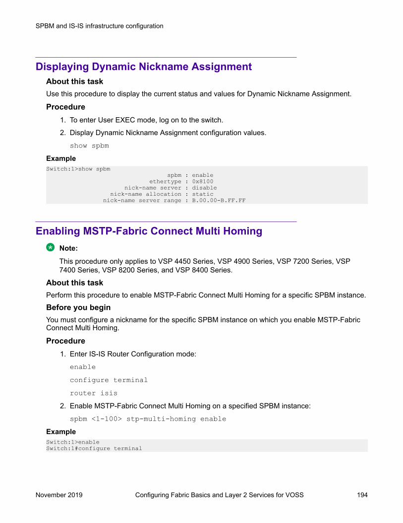
Displaying Dynamic Nickname AssignmentAbout this taskUse this procedure to display the current status and values for Dynamic Nickname Assignment.
Procedure1. To enter User EXEC mode, log on to the switch.
2. Display Dynamic Nickname Assignment configuration values.
show spbmExampleSwitch:1>show spbm spbm : enable ethertype : 0x8100 nick-name server : disable nick-name allocation : static nick-name server range : B.00.00-B.FF.FF
Enabling MSTP-Fabric Connect Multi HomingNote:
This procedure only applies to VSP 4450 Series, VSP 4900 Series, VSP 7200 Series, VSP7400 Series, VSP 8200 Series, and VSP 8400 Series.
About this taskPerform this procedure to enable MSTP-Fabric Connect Multi Homing for a specific SPBM instance.
Before you beginYou must configure a nickname for the specific SPBM instance on which you enable MSTP-FabricConnect Multi Homing.
Procedure1. Enter IS-IS Router Configuration mode:
enableconfigure terminalrouter isis
2. Enable MSTP-Fabric Connect Multi Homing on a specified SPBM instance:
spbm <1-100> stp-multi-homing enableExampleSwitch:1>enableSwitch:1#configure terminal
SPBM and IS-IS infrastructure configuration
November 2019 Configuring Fabric Basics and Layer 2 Services for VOSS 194

Switch:1(config)#router isisSwitch:1(config-isis)#spbm 1 stp-multi-homing enable
Variable definitionsUse data in the following table to use the spbm command.
Variable Value<1–100> Specifies the IS-IS SPBM instance ID to create an SPBM instance.stp-multi-homing enable Enables MSTP-Fabric Connect Multi Homing on the specific SPBM
instance. The default is disabled.
Determine the Root Bridge in an MSTP-Fabric Connect MultiHoming Configuration
Identify the root bridge by determining where the Common and Internal Spanning Tree (CIST)regional root MAC address is learned for the STP-reserved I-SID. Check which MAC address hasthe same first five octets as the CIST regional root MAC address.
About this taskWhen you enable MSTP-Fabric Connect Multi Homing, you can use the following two commands todetermine which BEB is the root bridge:
• show spanning-tree mstp status• show i-sid mac-address-entry 16777003
Procedure1. To enter User EXEC mode, log on to the switch.
2. Determine the CIST regional root:
show spanning-tree mstp status3. Determine which MAC address has the same first five octets as seen in the CIST regional
root MAC address:
show i-sid mac-address-entry 16777003ExampleIn the following example, bold text identifies the relevant information in the command output. In theoutput of the second command, the DEST-MAC shows 10:cd:ae:6e:d8:84, which is the system ID ofthe CIST regional root BEB, and the system name is BEB-1000.Switch:1>show spanning-tree mstp status
========================================================================================== MSTP Status==========================================================================================------------------------------------------------------------------------------------------Bridge Address : b0:ad:aa:4d:b8:00Cist Root : 80:00:10:cd:ae:6e:d8:00Cist Regional Root : 80:00:10:cd:ae:6e:d8:00Cist Root Port : fabric
SPBM and IS-IS infrastructure configuration using CLI
November 2019 Configuring Fabric Basics and Layer 2 Services for VOSS 195

Cist Root Cost : 0Cist Regional Root Cost : 2000000Cist Instance Vlan Mapped : 1-1024Cist Instance Vlan Mapped2k : 1025-2048Cist Instance Vlan Mapped3k : 2049-3072Cist Instance Vlan Mapped4k : 3073-4050,4053-4059Cist Max Age : 20 secondsCist Forward Delay : 15 secondsSwitch:1>show i-sid mac-address-entry 16777003============================================================================================== I-SID Fdb Table==============================================================================================I-SID STATUS MAC-ADDRESS INTERFACE TYPE DEST-MAC BVLAN DEST-SYSNAME----------------------------------------------------------------------------------------------16777003 learned 10:cd:ae:6e:d8:82 Port-1/9 REMOTE 10:cd:ae:6e:d8:84 4051 BEB-100016777003 learned 10:cd:ae:db:a4:83 Port-1/40 REMOTE 10:cd:ae:db:a4:84 4051 720816777003 learned b0:ad:aa:40:14:82 Port-1/40 REMOTE b0:ad:aa:40:14:84 4051 6222
SPBM and IS-IS infrastructure configuration using EDMThis section provides procedures to configure basic SPBM and IS-IS infrastructure using EnterpriseDevice Manager (EDM).
Important:
The EnableSpbmConfigMode boot flag must be enabled (default) before you can configureSPBM or IS-IS. To verify the setting, navigate to Configuration > Edit > Chassis and click onthe Boot Config tab.
Configuring required SPBM and IS-IS parametersAbout this taskUse the following procedure to configure the minimum required SPBM and IS-IS parameters toallow SPBM to operate on the switch. SPBM uses the Intermediate-System-to-Intermediate-System(IS-IS) link state routing protocol to provide a loop free Ethernet topology that creates a shortestpath topology from every node to every other node in the network based on node MAC addresses.
Procedure1. Configure SBPM B-VLANs:
Note:
Always configure two B-VLANs in the core to allow load distribution over both B-VLANs.
a. In the navigation pane, expand the Configuration > VLAN > VLANs folders.
b. Click the Basic tab.
c. Click Insert.d. In the type field, click spbm-bvlan.
SPBM and IS-IS infrastructure configuration
November 2019 Configuring Fabric Basics and Layer 2 Services for VOSS 196
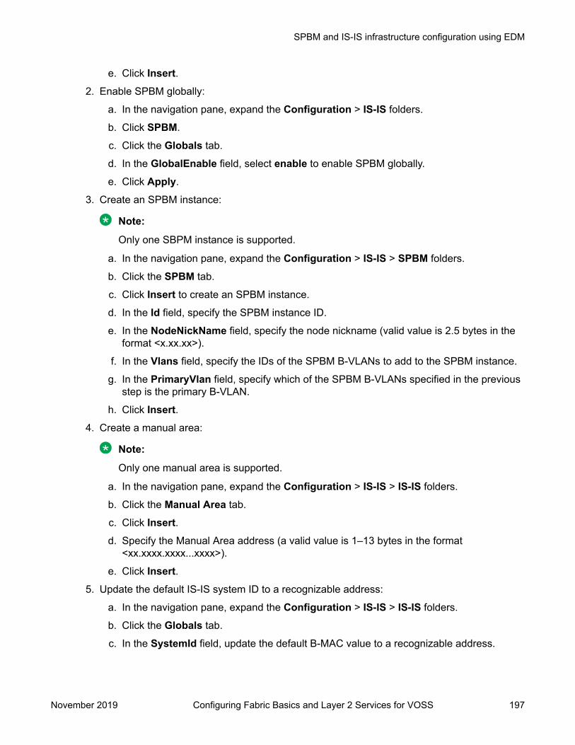
e. Click Insert.2. Enable SPBM globally:
a. In the navigation pane, expand the Configuration > IS-IS folders.
b. Click SPBM.
c. Click the Globals tab.
d. In the GlobalEnable field, select enable to enable SPBM globally.
e. Click Apply.
3. Create an SPBM instance:
Note:
Only one SBPM instance is supported.
a. In the navigation pane, expand the Configuration > IS-IS > SPBM folders.
b. Click the SPBM tab.
c. Click Insert to create an SPBM instance.
d. In the Id field, specify the SPBM instance ID.
e. In the NodeNickName field, specify the node nickname (valid value is 2.5 bytes in theformat <x.xx.xx>).
f. In the Vlans field, specify the IDs of the SPBM B-VLANs to add to the SPBM instance.
g. In the PrimaryVlan field, specify which of the SPBM B-VLANs specified in the previousstep is the primary B-VLAN.
h. Click Insert.4. Create a manual area:
Note:
Only one manual area is supported.
a. In the navigation pane, expand the Configuration > IS-IS > IS-IS folders.
b. Click the Manual Area tab.
c. Click Insert.d. Specify the Manual Area address (a valid value is 1–13 bytes in the format
<xx.xxxx.xxxx...xxxx>).
e. Click Insert.5. Update the default IS-IS system ID to a recognizable address:
a. In the navigation pane, expand the Configuration > IS-IS > IS-IS folders.
b. Click the Globals tab.
c. In the SystemId field, update the default B-MAC value to a recognizable address.
SPBM and IS-IS infrastructure configuration using EDM
November 2019 Configuring Fabric Basics and Layer 2 Services for VOSS 197

Note:
Although it is not strictly required for SPBM operation, you must change the IS-ISsystem ID from the default B-MAC value to a recognizable address to easily identifya switch. This helps to recognize the source and destination addresses fortroubleshooting purposes.
d. In the AdminState field, click on.
e. Click Apply.
6. Create an IS-IS circuit and enable SPBM on the circuit:
a. In the navigation pane, expand the Configuration > IS-IS folders.
b. Click the Interfaces tab.
c. Click Insert to create an IS-IS circuit.
d. In the IfIndex field, specify the port or MLT on which to create the IS-IS circuit.
e. Click Insert.f. Select the newly created IS-IS circuit entry, and click SPBM.
g. In the Interfaces SPBM tab, click Insert.h. In the State field, select enable.
i. Click Insert. This enables the SPBM instance on the IS-IS circuit.
j. Navigate back to the Interfaces tab.
k. In the AdminState field for the IS-IS circuit entry, select on to enable the IS-IS circuit.
l. Click Apply.
SPBM field descriptionsNote:
The following tables list the minimum required SPBM and IS-IS parameters to allow SPBM tooperate on the switch. For more detailed information on all of the parameters see theprocedures that follow. For more information on how to configure VLANs, see ConfiguringVLANs, Spanning Tree, and NLB for VOSS.
Use the data in the following table to use the VLANs Basic tab.
Name DescriptionType Specifies the type of VLAN:
• byPort
• byProtocolId
• spbm-bvlan
• private
Use the data in the following table to use the SPBM Globals tab.
SPBM and IS-IS infrastructure configuration
November 2019 Configuring Fabric Basics and Layer 2 Services for VOSS 198

Use the data in the following table to use the SPBM tab.Use the data in the following table to use the IS-IS Manual Area tab.
Name DescriptionAreaAddr Specifies the IS-IS manual area. Valid value is 1-13
bytes in the format <xx.xxxx.xxxx...xxxx>. Only onemanual area is supported. Use the same manualarea across the entire SPBM cloud. For IS-IS tooperate, you must configure at least one manualarea.
Use the data in the following table to use the IS-IS Globals tab.
Name Description
Use the data in the following table to use the IS-IS Interfaces tab.
Name DescriptionIndex The identifier of this circuit, unique within the
Intermediate System. This value is for SNMPIndexing purposes only and need not have anyrelation to any protocol value.
AdminState Specifies the administrative state of the circuit: on oroff.
Use the data in the following table to use the IS-IS Interfaces SPBM tab.
Name DescriptionState Specifies whether the SPBM interface is enabled or
disabled.
Job aidImportant:
After you have configured the SPBM nickname and enabled IS-IS. To maintain the samenickname with a different system ID, perform the following steps:
1. Disable IS-IS.
2. Change the system ID.
3. Change the nickname to a temporary one.
4. Enable IS-IS.
5. Wait up to 20 minutes for the LSPs with the original system ID to age out.
Note:
To check the age out time, use the show isis lsdb sysid <original-sys-id> command on any of the other SPB nodes in the network. When there is no
SPBM and IS-IS infrastructure configuration using EDM
November 2019 Configuring Fabric Basics and Layer 2 Services for VOSS 199

output from this command, proceed to the next step. The time left (in seconds) forthe LSPs to age out is shown under the column LIFETIME.
6. Disable IS-IS.
7. Change the nickname to the original nickname.
8. Enable IS-IS.
Displaying SPBM and IS-IS summary informationUse the following procedure to view a summary of SPBM and IS-IS protocol information.
Procedure1. In the navigation tree, expand the Configuration > IS-IS folders.
2. Click IS-IS.
3. Click the Protocol Summary tab.
Protocol Summary field descriptionsUse the data in the following table to use the Protocol Summary tab.
Name DescriptionGlobals ISISAdminState Indicates the global status of IS-IS on the switch.SystemId Indicates the IS-IS system ID for the switch. Valid value is a 6–
byte value in the format <xxxx.xxxx.xxxx>HostName Indicates a name for the system. This may be used as the host
name for dynamic host name exchange in accordance with RFC2763.
By default, the system name comes from the host nameconfigured at the system level.
Globals SPBMGlobalEnable Indicates whether SPBM is enabled or disabled at the global
level.NodeNickName Indicates the nickname for the SPBM instance globally. Valid
value is 2.5 bytes in the format <x.xx.xx>.PrimaryVlan Indicates the primary VLAN ID for this SPBM instance.SmltSplitBEB Indicates whether the switch is the primary or secondary IST
peer.ISIS Interfaces
Table continues…
SPBM and IS-IS infrastructure configuration
November 2019 Configuring Fabric Basics and Layer 2 Services for VOSS 200

Name DescriptionCircuit Index Displays the identifier of this IS-IS circuit, unique within the
Intermediate System. This is for SNMP Indexing purposes onlyand need not have any relation to any protocol value.
IfIndex Indicates the interface to which this circuit corresponds.AdminState Indicates the administrative state of the circuit: on or off.OperState Indicates the operational state of the circuit: up or down.ISIS Adjacency ViewCircuit Index Displays the identifier of this IS-IS circuit, unique within the
Intermediate System. This value is for SNMP Indexing purposesonly and need not have any relation to any protocol value.
AdjIndex Displays a unique value identifying the IS adjacency from allother such adjacencies on this circuit. This value is automaticallyassigned by the system when the adjacency is created
AdjIfIndex Indicates the interface to which this circuit corresponds.AdjState Indicates the state of the adjacency:
• down
• initializing
• up
• failedAdjNeighSysID Indicates the system ID of the neighboring Intermediate System.AdjHostName Indicates the host name listed in the LSP, or the system name if
the host name is not configured.
Displaying the SPBM I-SID informationUse the following procedure to display the SPBM Service Instance Identifier (I-SID) information. TheSPBM B-MAC header includes an I-SID with a length of 24 bits. This I-SID can be used to identifyand transmit any virtualized traffic in an encapsulated SPBM frame.
Procedure1. In the navigation pane, expand the Configuration > IS-IS folders.
2. Click SPBM.
3. Click the I-SID tab.
I-SID field descriptionsUse the data in the following table to use the I-SID tab.
SPBM and IS-IS infrastructure configuration using EDM
November 2019 Configuring Fabric Basics and Layer 2 Services for VOSS 201
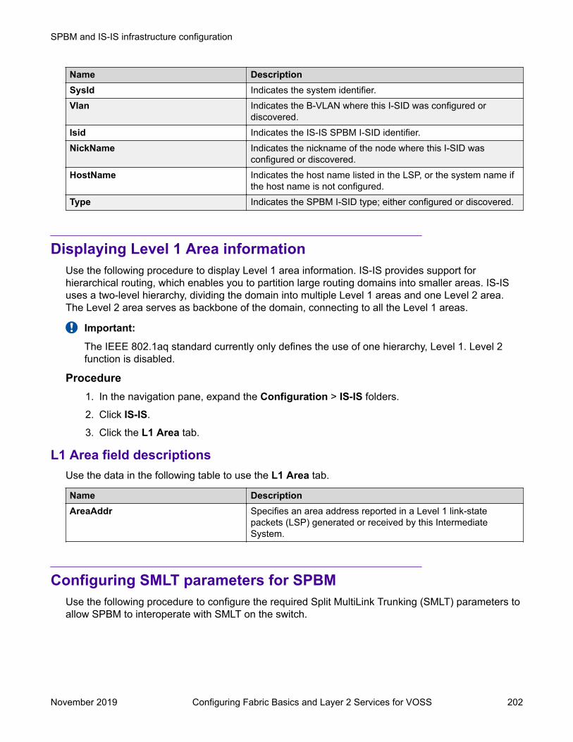
Name DescriptionSysId Indicates the system identifier.Vlan Indicates the B-VLAN where this I-SID was configured or
discovered.Isid Indicates the IS-IS SPBM I-SID identifier.NickName Indicates the nickname of the node where this I-SID was
configured or discovered.HostName Indicates the host name listed in the LSP, or the system name if
the host name is not configured.Type Indicates the SPBM I-SID type; either configured or discovered.
Displaying Level 1 Area informationUse the following procedure to display Level 1 area information. IS-IS provides support forhierarchical routing, which enables you to partition large routing domains into smaller areas. IS-ISuses a two-level hierarchy, dividing the domain into multiple Level 1 areas and one Level 2 area.The Level 2 area serves as backbone of the domain, connecting to all the Level 1 areas.
Important:
The IEEE 802.1aq standard currently only defines the use of one hierarchy, Level 1. Level 2function is disabled.
Procedure1. In the navigation pane, expand the Configuration > IS-IS folders.
2. Click IS-IS.
3. Click the L1 Area tab.
L1 Area field descriptionsUse the data in the following table to use the L1 Area tab.
Name DescriptionAreaAddr Specifies an area address reported in a Level 1 link-state
packets (LSP) generated or received by this IntermediateSystem.
Configuring SMLT parameters for SPBMUse the following procedure to configure the required Split MultiLink Trunking (SMLT) parameters toallow SPBM to interoperate with SMLT on the switch.
SPBM and IS-IS infrastructure configuration
November 2019 Configuring Fabric Basics and Layer 2 Services for VOSS 202

Note:• The assignment of primary and secondary roles to the vIST peers is automatic. The switch
with the lower system ID (between the two vIST peers) is primary, and the switch with thehigher system ID is secondary when default system-id values are being used.
• SMLT peer system ID is part of the required configuration. You must configure the SMLTpeer system ID as the nodal MAC of the peer device. In the IS-IS network, the nodal MACof devices should be eight apart from each other.
• When using the default hardware assigned system-id value, the SMLT Virtual BMAC isautomatically derived by comparing the system-id values of the two vIST peers. A value of0x01 plus the lower of the two system-id values is used as the SMLT Virtual BMAC.
When using a manually configured system-id value, the SMLT Virtual BMAC must also bemanually configured.
• An I-SID must be assigned to every VLAN that is a member of an L2 VSN. Also if an L2VSN is created on one vIST Peer, it must also be created on the other vIST peer.
Procedure1. In the navigation pane, expand the Configuration > IS-IS > SPBM folders.
2. Click the SPBM tab.
3. Use the SmltSplitBEB field to see whether the switch is the primary or secondary vIST peer.This field cannot be modified.
4. Use the SmltVirtualBmac field to specify a virtual MAC address that can be used by bothpeers.
5. Use the SmltPeerSysId field to specify the vIST peer B-MAC address.
6. Click Apply.
Enabling or disabling SPBM at the global levelUse the following procedure to enable or disable SPBM at the global level. SPBM uses theIntermediate-System-to-Intermediate-System (IS-IS) link state routing protocol to provide a loop freeEthernet topology that creates a shortest path topology from every node to every other node in thenetwork based on node MAC addresses.
Procedure1. In the navigation pane, expand the Configuration > IS-IS folders.
2. Click SPBM.
3. Click the Globals tab.
4. To enable or disable SPBM, click enable or disable in the GlobalEnable field.
5. To configure the global ethertype value, click the desired option in the GlobalEtherTypefield.
SPBM and IS-IS infrastructure configuration using EDM
November 2019 Configuring Fabric Basics and Layer 2 Services for VOSS 203
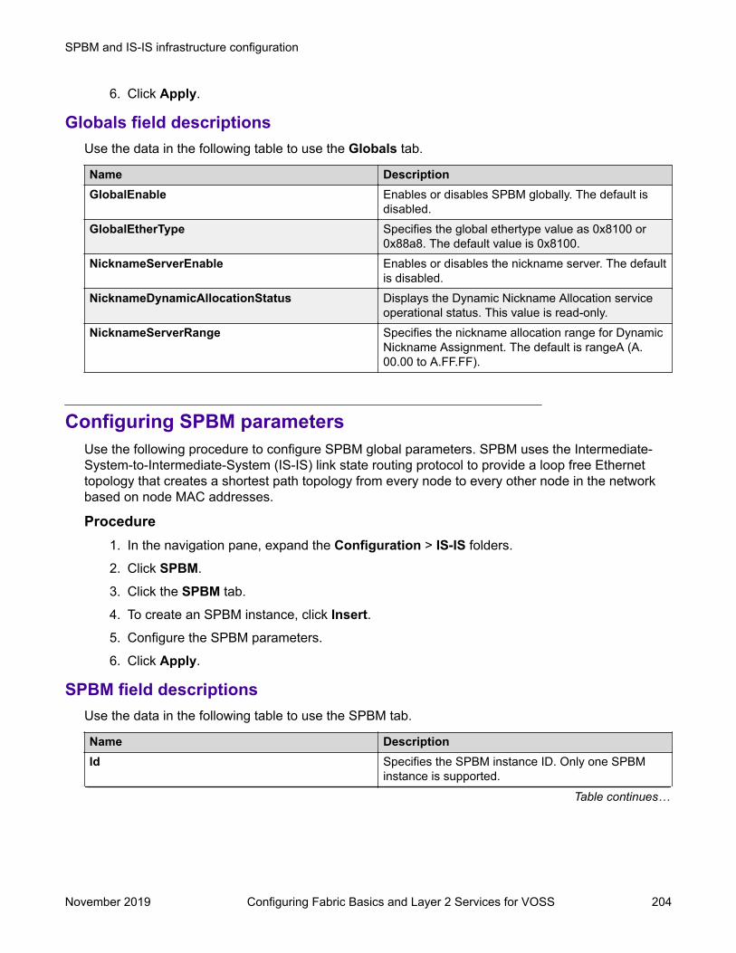
6. Click Apply.
Globals field descriptionsUse the data in the following table to use the Globals tab.
Name DescriptionGlobalEnable Enables or disables SPBM globally. The default is
disabled.GlobalEtherType Specifies the global ethertype value as 0x8100 or
0x88a8. The default value is 0x8100.NicknameServerEnable Enables or disables the nickname server. The default
is disabled.NicknameDynamicAllocationStatus Displays the Dynamic Nickname Allocation service
operational status. This value is read-only.NicknameServerRange Specifies the nickname allocation range for Dynamic
Nickname Assignment. The default is rangeA (A.00.00 to A.FF.FF).
Configuring SPBM parametersUse the following procedure to configure SPBM global parameters. SPBM uses the Intermediate-System-to-Intermediate-System (IS-IS) link state routing protocol to provide a loop free Ethernettopology that creates a shortest path topology from every node to every other node in the networkbased on node MAC addresses.
Procedure1. In the navigation pane, expand the Configuration > IS-IS folders.
2. Click SPBM.
3. Click the SPBM tab.
4. To create an SPBM instance, click Insert.5. Configure the SPBM parameters.
6. Click Apply.
SPBM field descriptionsUse the data in the following table to use the SPBM tab.
Name DescriptionId Specifies the SPBM instance ID. Only one SPBM
instance is supported.
Table continues…
SPBM and IS-IS infrastructure configuration
November 2019 Configuring Fabric Basics and Layer 2 Services for VOSS 204
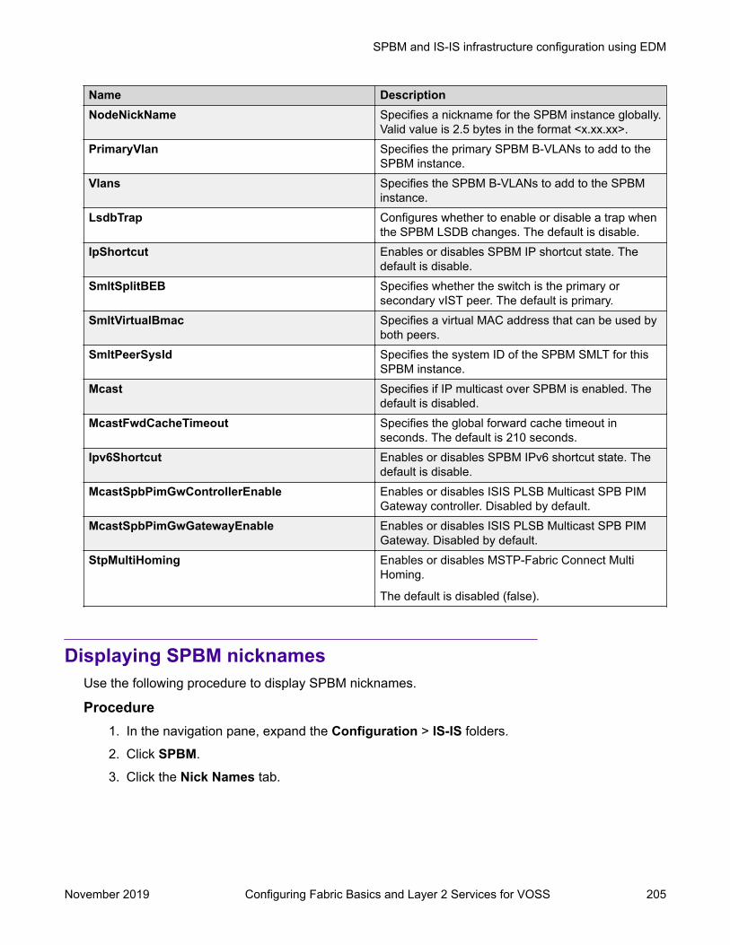
Name DescriptionNodeNickName Specifies a nickname for the SPBM instance globally.
Valid value is 2.5 bytes in the format <x.xx.xx>.PrimaryVlan Specifies the primary SPBM B-VLANs to add to the
SPBM instance.Vlans Specifies the SPBM B-VLANs to add to the SPBM
instance.LsdbTrap Configures whether to enable or disable a trap when
the SPBM LSDB changes. The default is disable.IpShortcut Enables or disables SPBM IP shortcut state. The
default is disable.SmltSplitBEB Specifies whether the switch is the primary or
secondary vIST peer. The default is primary.SmltVirtualBmac Specifies a virtual MAC address that can be used by
both peers.SmltPeerSysId Specifies the system ID of the SPBM SMLT for this
SPBM instance.Mcast Specifies if IP multicast over SPBM is enabled. The
default is disabled.McastFwdCacheTimeout Specifies the global forward cache timeout in
seconds. The default is 210 seconds.Ipv6Shortcut Enables or disables SPBM IPv6 shortcut state. The
default is disable.McastSpbPimGwControllerEnable Enables or disables ISIS PLSB Multicast SPB PIM
Gateway controller. Disabled by default.McastSpbPimGwGatewayEnable Enables or disables ISIS PLSB Multicast SPB PIM
Gateway. Disabled by default.StpMultiHoming Enables or disables MSTP-Fabric Connect Multi
Homing.
The default is disabled (false).
Displaying SPBM nicknamesUse the following procedure to display SPBM nicknames.
Procedure1. In the navigation pane, expand the Configuration > IS-IS folders.
2. Click SPBM.
3. Click the Nick Names tab.
SPBM and IS-IS infrastructure configuration using EDM
November 2019 Configuring Fabric Basics and Layer 2 Services for VOSS 205

Nickname field descriptionsUse the data in the following table to use the NickName tab.
Name DescriptionLevel Indicates the level at which this LSP appears.ID Indicates the 8 byte LSP ID, consisting of the SystemID, Circuit
ID, and Fragment Number.LifetimeRemain Indicates the remaining lifetime in seconds for the LSP.NickName Indicates the nickname for the SPBM node.HostName Indicates the hostname listed in the LSP, or the system name if
the host name is not configured.
Configuring interface SPBM parametersUse the following procedure to configure SPBM interface parameters.
Procedure1. In the navigation pane, expand the Configuration > IS-IS folders.
2. Click SPBM.
3. Click the Interfaces SPBM tab.
4. Configure the SPBM interface parameters.
5. Click Apply.
SPBM field descriptionsUse the data in the following table to use the Interfaces SPBM tab.
Name DescriptionIndex Specifies an Index value for the SPBM interface.SpbmId Specifies the SPBM ID.State Specifies whether the SPBM interface is enabled or
disabled.Type Configures the SPBM instance interface-type on the
IS-IS interface located on the specified port or MLT:ptpt or bcast. Only the point-to-point (ptpt) interfacetype is supported.
L1Metric Configures the SPBM instance l1-metric on the IS-ISinterface located on the specified port or MLT. Thedefault value is 10.
SPBM and IS-IS infrastructure configuration
November 2019 Configuring Fabric Basics and Layer 2 Services for VOSS 206

Configuring SPBM on an interfaceUse the following procedure to configure SPBM on an interface.
Procedure1. In the navigation pane, expand the Configuration > IS-IS folders.
2. Click IS-IS.
3. Click the Interfaces tab.
4. Click the SPBM button.
5. In the Interfaces SPBM tab, click Insert.6. Click Insert.
Interfaces SPBM field descriptionsUse the data in the following table to use the Interfaces SPBM tab.
Name DescriptionIndex Specifies an Index value for the SPBM interface.SpbmId Specifies the SPBM instance ID.State Specifies whether the SPBM interface is enabled or disabled.
The default is disabled.Type Configures the SPBM instance interface-type on the IS-IS
interface located on the specified port or MLT. Only the pt-ptinterface type is supported. The default is pt-pt.
L1Metric Configures the SPBM instance l1-metric on the IS-IS interfacelocated on the specified port or MLT. The default value is 10.
Displaying the IP unicast FIBUse the following procedure to display the IP unicast Forwarding Information Base (FIB). The tabshows IP routes from remote Backbone Edge Bridges (BEBs)
In SPBM, each node has a System ID, which also serves as Backbone MAC address (B-MAC) ofthe switch. These Backbone MAC addresses are populated into the SPBM VLAN ForwardingInformation Base (FIB). When the network topology is discovered and stored in the IS-IS link-statedatabase, each node calculates shortest path trees for each source node, so that a unicast pathnow exists from every node to every other node. With this information, each node populates unicastinformation received from SPBM into the FIB for forwarding purposes.
I-SIDs are only used for virtual services (Layer 2 VSNs and Layer 3 VSNs). If you only enable IPShortcuts on the Backbone Edge Bridges, I-SIDs are never exchanged in the network as IPShortcuts allows for Global Routing Table (GRT) IP networks to be transported across IS-IS.
SPBM and IS-IS infrastructure configuration using EDM
November 2019 Configuring Fabric Basics and Layer 2 Services for VOSS 207

The IP Unicast FIB tab displays all of the IS-IS routes in the IS-IS LSDB. The Preference column inthe IP Unicast FIB tab displays the IP route preference.
Routes within the same VSN are added to the LSDB with a default preference of 7. Inter-VSN routesare added to the LSDB with a route preference of 200. IS-IS accept policies allow you to change theroute preference for incoming routes. If the same route is learned from multiple sources withdifferent route preferences, then the routes are not considered equal cost multipath (ECMP) routes.The route with the lowest route preference is the preferred route. In Layer 2, in the event of a tie-break between routes from multiple sources, the tie-breaking is based on cost and hop count.
Procedure1. In the navigation pane, expand the Configuration > IS-IS folders.
2. Click SPBM.
3. Click the IP Unicast FIB tab.
IP Unicast FIB field descriptionsUse the data in the following table to use the IP Unicast FIB tab.
Name DescriptionVrfId Specifies the VRF ID of the IP unicast FIB entry, 0 indicates
NRE.DestinationIpAddrType Specifies the address type of the destination IP address.DestinationIpAddr Specifies the destination IP Address of the IP unicast FIB entry.DestinationMask Specifies the destination IP mask of the IP unicast FIB entryNextHopBmac Specifies the nexthop B-MAC of the IP unicast FIB entry.DestId Specifies the destination ISID of the IP unicast FIB entry.Vlan Specifies the VLAN of the IP unicast FIB entry.Isid Specifies the I-SID of the IP unicast FIB entry.NextHopName Specifies the nexthop hostname of the IP unicast FIB entry.OutgoingPort Specifies the outgoing port of the IP unicast FIB entry.PrefixCost Specifies the prefix cost of the IP unicast FIB entry.SpbmCost Specifies the B-MAC cost of the IP unicast FIB entry.Preference Specifies the IP Route preference of the IP unicast FIB entryMetricType Specifies the IP Metric Type of the IP unicast FIB entry.
Displaying the IPv6 unicast FIBUse the following procedure to display the IPv6 unicast Forwarding Information Base (FIB). The tabshows IPv6 routes from remote Backbone Edge Bridges (BEBs)
In SPBM, each node has a System ID, which also serves as Backbone MAC address (B-MAC) ofthe switch. These Backbone MAC addresses are populated into the SPBM VLAN Forwarding
SPBM and IS-IS infrastructure configuration
November 2019 Configuring Fabric Basics and Layer 2 Services for VOSS 208

Information Base (FIB). When the network topology is discovered and stored in the IS-IS link-statedatabase, each node calculates shortest path trees for each source node, so that a unicast pathnow exists from every node to every other node. With this information, each node populates unicastinformation received from SPBM into the FIB for forwarding purposes.
I-SIDs are only used for virtual services (Layer 2 VSNs and Layer 3 VSNs). If you only enable IPShortcuts on the Backbone Edge Bridges, I-SIDs are never exchanged in the network as IPShortcuts allows for Global Routing Table (GRT) IP networks to be transported across IS-IS.
Procedure1. In the navigation pane, expand the Configuration > IS-IS folders.
2. Click SPBM.
3. Click the IPv6 Unicast FIB tab.
IPv6 Unicast FIB Field DescriptionsUse the data in the following table to use the IPv6 Unicast FIB tab.
Name DescriptionVrfId Specifies the VRF ID of the IPv6 unicast FIB entry, 0 indicates
NRE.DestinationIpAddrType Specifies the address type of the destination IPv6 address.DestinationIpAddr Specifies the destination IPv6 Address of the IPv6 unicast FIB
entry.DestinationMask Specifies the destination IPv6 mask of the IPv6 unicast FIB entryNextHopBmac Specifies the nexthop B-MAC of the IPv6 unicast FIB entry.DestIsid Specifies the destination I-SID of the IPv6 unicast FIB entry.Vlan Specifies the VLAN of the IPv6 unicast FIB entry.Isid Specifies the I-SID of the IPv6 unicast FIB entry.NextHopName Specifies the nexthop hostname of the IPv6 unicast FIB entry.OutgoingPort Specifies the outgoing port of the IPv6 unicast FIB entry.PrefixCost Specifies the prefix cost of the IPv6 unicast FIB entry.SpbmCost Specifies the B-MAC cost of the IPv6 unicast FIB entry.MetricType Specifies the Metric Type of the IPv6 unicast FIB entry.
Displaying the unicast FIBUse the following procedure to display the unicast FIB.
In SPBM, B-MAC addresses are carried within the IS-IS link-state database. To do this, SPBMsupports an IS-IS TLV that advertises the I-SID and B-MAC information across the network. Eachnode has a System ID, which also serves as Backbone MAC address (B-MAC) of the switch. TheseBackbone MAC addresses are populated into the SPBM VLAN Forwarding Information Base (FIB).
SPBM and IS-IS infrastructure configuration using EDM
November 2019 Configuring Fabric Basics and Layer 2 Services for VOSS 209

When the network topology is discovered and stored in the IS-IS link-state database, each nodecalculates shortest path trees for each source node, so that a unicast path now exists from everynode to every other node. With this information, each node populates unicast information receivedfrom SPBM into the FIB for forwarding purposes.
Procedure1. In the navigation pane, expand the Configuration > IS-IS folders.
2. Click SPBM.
3. Click the Unicast FIB tab.
Unicast FIB field descriptionsUse the data in the following table to use the Unicast FIB tab.
Name DescriptionSysId Specifies the system ID of the node where the unicast FIB entry
originated.Vlan Specifies the VLAN of the unicast FIB entry.DestinationMacAddr Specifies the destination MAC Address of the unicast FIB entry.OutgoingPort Specifies the outgoing port of the unicast FIB entry.HostName Specifies the host name of the node where unicast FIB entry
originated.Cost Specifies the cost of the unicast FIB entry.
Displaying LSP summary informationUse the following procedure to display link-state packet (LSP) summary information. Link StatePackets (LSP) contain information about the state of adjacencies or defined and distributed staticroutes. Intermediate System to Intermediate System (IS-IS) exchanges this information withneighboring IS-IS routers at periodic intervals.
Procedure1. In the navigation pane, expand the Configuration > IS-IS folders.
2. Click IS-IS.
3. Click the LSP Summary tab.
LSP Summary field descriptionsUse the data in the following table to use the LSP Summary tab.
Name DescriptionLevel Specifies the level at which this LSP appears.
Table continues…
SPBM and IS-IS infrastructure configuration
November 2019 Configuring Fabric Basics and Layer 2 Services for VOSS 210

Name DescriptionID Specifies the 8 byte LSP ID, consisting of the SystemID, Circuit
ID, and Fragment Number.Seq Specifies the sequence number for this LSP.Checksum Specifies the 16 bit Fletcher Checksum for this LSP.LifetimeRemain The remaining lifetime in seconds for this LSP.HostName The hostname listed in LSP, or the system name if host name is
not configured.
Displaying IS-IS adjacenciesUse the following procedure to display IS-IS adjacency information. The platform sends IS-IS Hello(IIH) packets to discover IS-IS neighbors and establish and maintain IS-IS adjacencies. The platformcontinues to send IIH packets to maintain the established adjacencies. For two nodes to form anadjacency the B-VLAN pairs for the primary B-VLAN and secondary B-VLAN must match.
Procedure1. In the navigation pane, expand the Configuration > IS-IS folders.
2. Click IS-IS.
3. Click the Adjacency tab.
Adjacency field descriptionsUse the data in the following table to use the Adjacency tab.
Name DescriptionInterface Specifies the IS-IS interface on which the adjacency is found.Level Indicates the level of the IS-IS interface (Level 1 [default] or
Level 2).State Specifies the state of the adjacency:
• down
• initializing
• up
• failedLastUpTime Indicates when the adjacency most recently entered the state
up, measured in hundredths of a second since the last re-initialization of the network management subsystem. Displays 0if the adjacency has never been in state up.
NeighPriority Specifies the priority of the neighboring Intermediate System forbecoming the Designated Intermediate System.
Table continues…
SPBM and IS-IS infrastructure configuration using EDM
November 2019 Configuring Fabric Basics and Layer 2 Services for VOSS 211

Name DescriptionHoldTimer Specifies the holding time in seconds for this adjacency. This
value is based on received IS-IS Hello (IIH) PDUs and theelapsed time since receipt.
NeighSysID Specifies the system ID of the neighboring Intermediate System.AdjHostName Specifies the host name listed in the LSP, or the system name if
host name is not configured.ParallelActive Specifies if the current adjacency among all the parallel
adjacencies between two nodes is active.
• true
• false
Configuring IS-IS global parametersUse the following procedure to configure IS-IS global parameters. SPBM uses IS-IS to discovernetwork topology, build shortest path trees between network nodes, and communicate networkinformation in the control plane.
Procedure1. In the navigation pane, expand the Configuration > IS-IS folders.
2. Click IS-IS.
3. From the Globals tab, configure the global IS-IS parameters.
4. Click Apply.
Globals field descriptionsUse the data in the following table to use the Globals tab.
Name DescriptionAdminState Specifies the global status of IS-IS on the switch: on
or off. The default is off.LevelType Sets the router type globally:
• level1: Level-1 router type
• level1and2: Level–1/2 router type is not supported.
The default value is level1.SystemId Specifies the IS-IS system ID for the switch. Valid
value is a 6–byte value in the format<xxxx.xxxx.xxxx>.
Table continues…
SPBM and IS-IS infrastructure configuration
November 2019 Configuring Fabric Basics and Layer 2 Services for VOSS 212

Name DescriptionImportant:
After you have configured the SPBM nicknameand enabled IS-IS, if you require a change ofthe system ID, you must also change thenickname. However, for naming conventionpurposes or configuration purposes, you maynot want to change the nickname. To maintainthe same nickname with a different system ID,see Job Aid on page 102.
MaxLspGenInt Specifies the maximum interval, in seconds, betweengenerated LSPs by this Intermediate system. Thevalue must be greater than any value configured forRxmtLspInt.
The default value is 900 seconds.CsnpInt Specifies the Complete Sequence Number Packet
(CSNP) interval in seconds. This is a system levelparameter that applies for L1 CSNP generation on allinterfaces.
The default value is 10.RxmtLspInt Specifies the minimum time between retransmission
of an LSP. This defines how fast the switch resendsthe same LSP. This is a system level parameter thatapplies for L1 retransmission of LSPs.
The default value is 5 seconds.PSNPInterval Specifies the Partial Sequence Number Packet
(PSNP) interval in seconds. This is a system levelparameter that applies for L1 PSNP generation on allinterfaces.
The default value is 2.SpfDelay Specifies the SPF delay in milliseconds. This value is
used to pace successive SPF runs. The timerprevents two SPF runs from being scheduled veryclosely.
The default value is 100 milliseconds.HostName Specifies a name for the system. This may be used
as the host name for dynamic host name exchangein accordance with RFC 2763.
By default, the system name comes from the hostname configured at the system level.
IpSourceAddress Specifies IP source address for SPBM IP shortcuts.Ipv6SourceAddressType Click ipv6 to use IPv6 addresses.
Table continues…
SPBM and IS-IS infrastructure configuration using EDM
November 2019 Configuring Fabric Basics and Layer 2 Services for VOSS 213

Name DescriptionIpv6SourceAddress Specifies IPv6 source address for SPBM IP
shortcuts.IpTunnelSourceAddress Specifies the IS-IS IP tunnel source address.IpTunnelVrf Specifies the VRF name associated with the IP
tunnel.MgmtIpAddr Specifies the DvR management IP address for this
node, in the DvR domain.BackboneEnable Select to enable this node to join the DvR backbone
so that it can receive redistributed DvR host routesfrom all DvR Controllers in the network.
FanMember Specifies whether the node is a member of theFabric Area Network (FAN) .
DynamicallyLearnedArea For FAN members, specifies the IS-IS area that isdynamically learned from the neighbor’s Hello PDU ifthe node does not have the IS-IS manual areaconfigured.
Configuring system-level IS-IS parametersUse the following procedure to configure system-level IS-IS parameters.
Procedure1. In the navigation pane, expand the Configuration > IS-IS > IS-IS folders.
2. Click the System Level tab.
3. Configure the IS-IS system level parameters.
4. Click Apply.
System Level field descriptionsUse the data in the following table to use the System Level tab.
Name DescriptionIndex Specifies the level: l1 or l2.
Only l1 is supported.State Specifies the state of the database at this level. The value 'off'
indicates that IS-IS is not active at this level. The value 'on'indicates that IS-IS is active at this level, and not overloaded.The value 'waiting' indicates a database that is low on anessential resources, such as memory. The administrator mayforce the state to 'overloaded' by setting the object
Table continues…
SPBM and IS-IS infrastructure configuration
November 2019 Configuring Fabric Basics and Layer 2 Services for VOSS 214

Name DescriptionSetOverload. If the state is 'waiting' or 'overloaded', youoriginate LSPs with the Overload bit set.
SetOverload Sets or clears the overload condition. The possible values aretrue or false.
The default value is false.SetOverloadUntil Sets the IS-IS overload-on-startup value in seconds. The
overload-on-startup value is used as a timer to control when tosend out LSPs with the overload bit cleared after IS-IS startup.
Note:
If you configure SetOverloadUntil to a number other thanzero, then the overload bit is set at this level when theAdminState variable goes to the state 'on' for thisIntermediate System.
After the SetOverloadUntil seconds elapse, the overloadflag remains set if the implementation runs out of memoryor if you configured it manually using SetOverload to true.
If SetOverload is false, the system clears the overload bitafter SetOverloadUntil seconds elapse, if the system hasnot run out of memory.
The default value is 20.MetricStyle Specifies the IS-IS metric type. Available values are narrow,
wide or both. Only wide is supported.
Displaying IS-IS system statisticsUse the following procedure to display Intermediate-System-to-Intermediate-System (IS-IS) systemstatistics.
Procedure1. In the navigation pane, expand the Configuration > IS-IS folders.
2. Click Stats.
3. Click the System Stats tab.
System Stats field descriptionsUse the data in the following table to use the System Stats tab.
SPBM and IS-IS infrastructure configuration using EDM
November 2019 Configuring Fabric Basics and Layer 2 Services for VOSS 215

Name DescriptionCorrLSPs Indicates the number of corrupted in-memory link-state packets
(LSPs) detected. LSPs received from the wire with a badchecksum are silently dropped and not counted.
AuthFails Indicates the number of authentication key failures recognizedby this Intermediate System.
LSPDbaseOloads Indicates the number of times the LSP database has becomeoverloaded.
ManAddrDropFromAreas Indicates the number of times a manual address has beendropped from the area.
AttmptToExMaxSeqNums Indicates the number of times the IS has attempted to exceedthe maximum sequence number.
SeqNumSkips Indicates the number of times a sequence number skip hasoccurred.
OwnLSPPurges Indicates the number of times a zero-aged copy of the system'sown LSP is received from some other node.
IDFieldLenMismatches Indicates the number of times a PDU is received with a differentvalue for ID field length to that of the receiving system.
PartChanges Indicates partition changes.AbsoluteValue Displays the counter value.Cumulative Displays the total value since you opened the Stats tab.Average/sec Displays the average value for each second.Minimum/sec Displays the minimum value for each second.Maximum/sec Displays the maximum value for each second.LastVal/sec Displays the last value for each second.
Configuring IS-IS interfacesUse the following procedure to configure IS-IS interfaces. SPBM uses IS-IS to discover networktopology, build shortest path trees between network nodes, and communicate network information inthe control plane.
Procedure1. In the navigation pane, expand the Configuration > IS-IS folders.
2. Click IS-IS.
3. Click the Interfaces tab.
4. Configure the IS-IS interface parameters.
5. Click Apply.
SPBM and IS-IS infrastructure configuration
November 2019 Configuring Fabric Basics and Layer 2 Services for VOSS 216

Interfaces field descriptionsUse the data in the following table to use the Interfaces tab.
Name DescriptionIndex The identifier of this circuit, unique within the
Intermediate System. This value is for SNMPIndexing purposes only and need not have anyrelation to any protocol value.
IfIndex Specifies the interface on which the circuit isconfigured (port or MLT).
Type Specifies the IS-IS circuit type. Only the point-to-point (PtToPt) interface type is supported.
AdminState Specifies the administrative state of the circuit: on oroff.
OperState Specifies the operational state of the circuit.AuthType Specifies the authentication type:
• none
• simple: If selected, you must also specify a keyvalue but the key id is optional. Simple passwordauthentication uses a text password in thetransmitted packet. The receiving router uses anauthentication key (password) to verify the packet.
• hmac-md5: If selected, you must also specify a keyvalue, but the key-id is optional. MD5authentication creates an encoded checksum inthe transmitted packet. The receiving router usesan authentication key (password) to verify the MD5checksum of the packet. There is an optional keyID.
• hmac-sha–256: If selected, you must also specify akey value, but the key-id is optional. With SHA-256authentication, the switch adds an hmac-sha–256digest to each Hello packet. The switch thatreceives the Hello packet computes the digest ofthe packet and compares it with the receiveddigest. If the digests match, the packet is accepted.If the digests do not match, the receiving switchdiscards the packet. There is an optional key ID.
Note:
Secure Hashing Algorithm 256 bits (SHA-256)is a cipher and a cryptographic hash functionof SHA2 authentication. You can useSHA-256 to authenticate IS-IS Hello
Table continues…
SPBM and IS-IS infrastructure configuration using EDM
November 2019 Configuring Fabric Basics and Layer 2 Services for VOSS 217

Name Description
messages. This authentication method usesthe SHA-256 hash function and a secret keyto establish a secure connection betweenswitches that share the same key.
This feature is in full compliance with RFC5310.
The default is none.AuthKey Specifies the authentication key.KeyId Specifies the authentication key ID.LevelType Specifies the router type globally:
• level1: Level-1 router type
• level 1and2: Level–1/2 router type. This type is notsupported.
The default value is level1.NumAdj Specifies the number of adjacencies on this circuit.NumUpAdj Specifies the number of adjacencies that are up.AutoNniEnable Enable to have the node create an IS-IS interface,
attach the interface to an SPBM instance, and thenenable IS-IS on the port interface.
This field appears on the Insert Interfaces dialog boxand applies to port interfaces only.
Table continues…
Configuring IS-IS interface level parametersUse the following procedure to configure IS-IS interface level parameters. SPBM uses IS-IS todiscover network topology, build shortest path trees between network nodes, and communicatenetwork information in the control plane.
Procedure1. In the navigation pane, expand the Configuration > IS-IS folders.
2. Click IS-IS.
3. Click the Interfaces Level tab.
4. Configure the IS-IS interface level parameters.
5. Click Apply.
SPBM and IS-IS infrastructure configuration
November 2019 Configuring Fabric Basics and Layer 2 Services for VOSS 218

Interfaces field descriptionsUse the data in the following table to use the Interfaces Level tab.
Name DescriptionIndex The identifier of this circuit, unique within the Intermediate
System. This value is for SNMP Indexing purposes only andneed not have any relation to any protocol value.
Level Specifies the router type globally:
• l1: Level1 router type
• l12: Level1/Level2 router type. This type is not supported.
The default value is l1.ISPriority Specifies an integer sub-range for IS-IS priority. The default is
64.HelloTimer Configures the level 1 hello interval.
Specifies the maximum period, in milliseconds, between IS-ISHello Packets (IIH) PDUs on multiaccess networks at this levelfor LANs. The value at Level1 is used as the period betweenHellos on Level1/Level2 point to point circuits. Setting this valueat Level 2 on an Level1/Level2 point-to-point circuit results in anerror of InconsistentValue.
The default value is 9000 milliseconds or 9 seconds.HelloMultiplier Configures the level 1 hello multiplier. The default value is 3
seconds.DRHelloTimer Indicates the period, in milliseconds, between Hello PDUs on
multiaccess networks when this Intermediate System is theDesignated Intermediate System. The default is 3.
Displaying IS-IS interface countersUse the following procedure to display IS-IS interface counters.
Procedure1. In the navigation pane, expand the Configuration > IS-IS folders.
2. Click Stats.
3. Click the Interface Counters tab.
Interface Counters field descriptionsUse the data in the following table to use the Interface Counters tab.
SPBM and IS-IS infrastructure configuration using EDM
November 2019 Configuring Fabric Basics and Layer 2 Services for VOSS 219
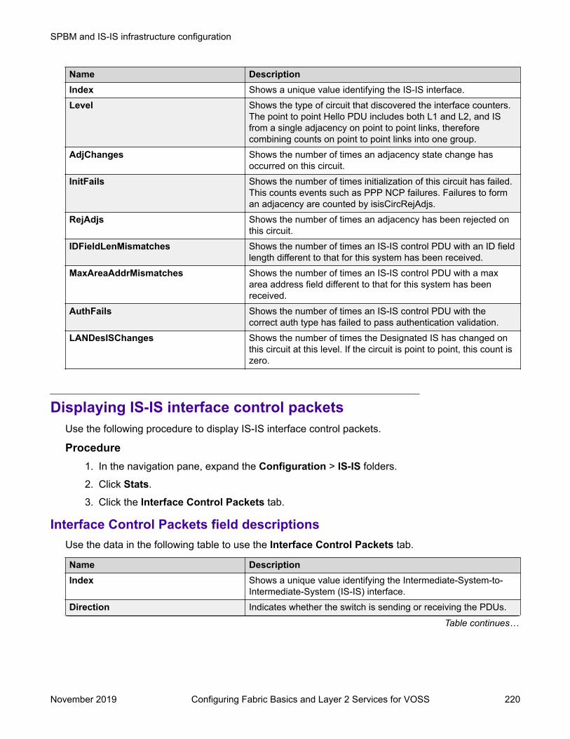
Name DescriptionIndex Shows a unique value identifying the IS-IS interface.Level Shows the type of circuit that discovered the interface counters.
The point to point Hello PDU includes both L1 and L2, and ISfrom a single adjacency on point to point links, thereforecombining counts on point to point links into one group.
AdjChanges Shows the number of times an adjacency state change hasoccurred on this circuit.
InitFails Shows the number of times initialization of this circuit has failed.This counts events such as PPP NCP failures. Failures to forman adjacency are counted by isisCircRejAdjs.
RejAdjs Shows the number of times an adjacency has been rejected onthis circuit.
IDFieldLenMismatches Shows the number of times an IS-IS control PDU with an ID fieldlength different to that for this system has been received.
MaxAreaAddrMismatches Shows the number of times an IS-IS control PDU with a maxarea address field different to that for this system has beenreceived.
AuthFails Shows the number of times an IS-IS control PDU with thecorrect auth type has failed to pass authentication validation.
LANDesISChanges Shows the number of times the Designated IS has changed onthis circuit at this level. If the circuit is point to point, this count iszero.
Displaying IS-IS interface control packetsUse the following procedure to display IS-IS interface control packets.
Procedure1. In the navigation pane, expand the Configuration > IS-IS folders.
2. Click Stats.
3. Click the Interface Control Packets tab.
Interface Control Packets field descriptionsUse the data in the following table to use the Interface Control Packets tab.
Name DescriptionIndex Shows a unique value identifying the Intermediate-System-to-
Intermediate-System (IS-IS) interface.Direction Indicates whether the switch is sending or receiving the PDUs.
Table continues…
SPBM and IS-IS infrastructure configuration
November 2019 Configuring Fabric Basics and Layer 2 Services for VOSS 220

Name DescriptionHello Indicates the number of IS-IS Hello frames seen in this direction
at this level.LSP Indicates the number of IS-IS LSP frames seen in this direction
at this level.CSNP Indicates the number of IS-IS Complete Sequence Number
Packets (CSNP) frames seen in this direction at this level.PSNP Indicates the number of IS-IS Partial Sequence Number Packets
(PSNP) frames seen in this direction at this level.
Graphing IS-IS interface countersUse the following procedure to graph IS-IS interface counters.
Procedure1. In the navigation pane, expand the Configuration > IS-IS folders.
2. Click IS-IS.
3. Click the Interfaces tab.
4. Select an existing interface.
5. Click the Graph button.
Interface Counters field descriptionsThe following table describes the fields in the Interface Counters tab.
Name DescriptionInitFails Indicates the number of times initialization of this circuit has
failed. This counts events such as PPP NCP failures.RejAdjs Indicates the number of times an adjacency has been rejected
on this circuit.IDFieldLenMismatches Indicates the number of times an Intermediate-System-to-
Intermediate-System (IS-IS) control PDU with an ID field lengthdifferent from that for this system has been received.
MaxAreaAddrMismatches Indicates the number of times an IS-IS control PDU with a maxarea address field different from that for this system has beenreceived.
AuthFails Indicates the number of times an IS-IS control PDU with thecorrect auth type has failed to pass authentication validation.
LANDesISChanges Indicates the number of times the Designated IS has changedon this circuit at this level. If the circuit is point to point, this countis zero.
Table continues…
SPBM and IS-IS infrastructure configuration using EDM
November 2019 Configuring Fabric Basics and Layer 2 Services for VOSS 221

Name DescriptionAbsoluteValue Displays the counter value.Cumulative Displays the total value since you opened the Stats tab.Average/Sec Displays the average value for each second.Minimum/Sec Displays the minimum value for each second.Maximum/Sec Displays the maximum value for each second.Last Val/Sec Displays the last value for each second.
Graphing IS-IS interface sending control packet statisticsUse the following procedure to graph IS-IS interface receiving control packet statistics.
Procedure1. In the navigation pane, expand the Configuration > IS-IS folders.
2. Click IS-IS.
3. Click the Interfaces tab.
4. Select an existing interface.
5. Click the Graph button.
6. Click the Interface Sending Control Packets tab.
Interface Sending Control Packets field descriptionsThe following table describes the fields in the Interface Sending Control Packets tab.
Name DescriptionHello Indicates the number of IS-IS Hello (IIH) PDUs seen in this
direction at this level. Point-to-Point IIH PDUs are counted at thelowest enabled level: at L1 on L1 or L1L2 circuits, and at L2otherwise.
LSP Indicates the number of IS-IS LSP frames seen in this directionat this level.
CSNP Indicates the number of IS-IS Complete Sequence NumberPacket (CSNP) frames seen in this direction at this level.
PSNP Indicates the number of IS-IS Partial Sequence Number Packets(PSNPs) seen in this direction at this level.
AbsoluteValue Displays the counter value.Cumulative Displays the total value since you opened the Stats tab.Average/Sec Displays the average value for each second.Minimum/Sec Displays the minimum value for each second.
Table continues…
SPBM and IS-IS infrastructure configuration
November 2019 Configuring Fabric Basics and Layer 2 Services for VOSS 222
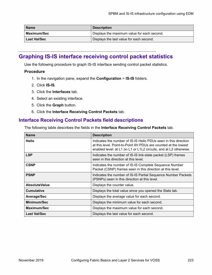
Name DescriptionMaximum/Sec Displays the maximum value for each second.Last Val/Sec Displays the last value for each second.
Graphing IS-IS interface receiving control packet statisticsUse the following procedure to graph IS-IS interface sending control packet statistics.
Procedure1. In the navigation pane, expand the Configuration > IS-IS folders.
2. Click IS-IS.
3. Click the Interfaces tab.
4. Select an existing interface.
5. Click the Graph button.
6. Click the Interface Receiving Control Packets tab.
Interface Receiving Control Packets field descriptionsThe following table describes the fields in the Interface Receiving Control Packets tab.
Name DescriptionHello Indicates the number of IS-IS Hello PDUs seen in this direction
at this level. Point-to-Point IIH PDUs are counted at the lowestenabled level: at L1 on L1 or L1L2 circuits, and at L2 otherwise.
LSP Indicates the number of IS-IS link-state packet (LSP) framesseen in this direction at this level.
CSNP Indicates the number of IS-IS Complete Sequence NumberPacket (CSNP) frames seen in this direction at this level.
PSNP Indicates the number of IS-IS Partial Sequence Number Packets(PSNPs) seen in this direction at this level.
AbsoluteValue Displays the counter value.Cumulative Displays the total value since you opened the Stats tab.Average/Sec Displays the average value for each second.Minimum/Sec Displays the minimum value for each second.Maximum/Sec Displays the maximum value for each second.Last Val/Sec Displays the last value for each second.
SPBM and IS-IS infrastructure configuration using EDM
November 2019 Configuring Fabric Basics and Layer 2 Services for VOSS 223
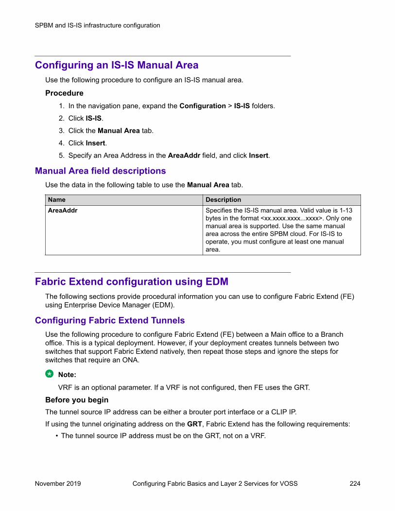
Configuring an IS-IS Manual AreaUse the following procedure to configure an IS-IS manual area.
Procedure1. In the navigation pane, expand the Configuration > IS-IS folders.
2. Click IS-IS.
3. Click the Manual Area tab.
4. Click Insert.5. Specify an Area Address in the AreaAddr field, and click Insert.
Manual Area field descriptionsUse the data in the following table to use the Manual Area tab.
Name DescriptionAreaAddr Specifies the IS-IS manual area. Valid value is 1-13
bytes in the format <xx.xxxx.xxxx...xxxx>. Only onemanual area is supported. Use the same manualarea across the entire SPBM cloud. For IS-IS tooperate, you must configure at least one manualarea.
Fabric Extend configuration using EDMThe following sections provide procedural information you can use to configure Fabric Extend (FE)using Enterprise Device Manager (EDM).
Configuring Fabric Extend TunnelsUse the following procedure to configure Fabric Extend (FE) between a Main office to a Branchoffice. This is a typical deployment. However, if your deployment creates tunnels between twoswitches that support Fabric Extend natively, then repeat those steps and ignore the steps forswitches that require an ONA.
Note:
VRF is an optional parameter. If a VRF is not configured, then FE uses the GRT.
Before you beginThe tunnel source IP address can be either a brouter port interface or a CLIP IP.If using the tunnel originating address on the GRT, Fabric Extend has the following requirements:
• The tunnel source IP address must be on the GRT, not on a VRF.
SPBM and IS-IS infrastructure configuration
November 2019 Configuring Fabric Basics and Layer 2 Services for VOSS 224

Note:A Best Practice is to use separate IP addresses for the SPBM IP Shortcuts ip-source-address command and the Fabric Extend ip-tunnel-source-address command.However, if you want these IP addresses to be the same, you MUST exclude the ip-source-address address with an IS-IS accept policy. You cannot use the redistributecommand with a route map exclusion.Specify a CLIP interface to use as the source address for SPBM IP shortcuts.
• If IP Shortcuts is enabled, you must configure an IS-IS accept policy or exclude route-map toensure that tunnel destination IP addresses are not learned through IS-IS.
If you are using the tunnel originating address on a VRF, Fabric Extend has the followingrequirements:
• Configure a CLIP and tunnel source IP address on the VRF.• Remote management of the VSP 4000 is only possible after establishing IP Shortcut over IS-
IS. (Alternatively, you can enable GRT-VRF redistribution locally.)
About this taskConfiguring Fabric Extend consists of two primary tasks: configuring the tunnel source address andconfiguring the logical interface. These tasks must be completed on both ends of the tunnel.Note that the VSP 4000 source address command is different than other platforms. Also note thatthe logical interface commands are different between Layer 2 and Layer 3 networks.
ProcedureThe following steps are for platforms that support FE natively:
1. In the navigation pane, expand the Configuration > IS-IS > IS-IS folders.
2. Click the Globals tab.
3. In the IpTunnelSourceAddress field, enter the IP tunnel source address.
4. If you are using a VRF, select its name from the drop down menu in the IpTunnelVrf field.
5. Click Apply.
The following steps are for platforms that require an ONA to support FE:
Note:
The interface VLAN connecting to the ONA network port is always in the GRT and themember port that the VLAN is part of is always an access port.
6. In the navigation pane, expand the Configuration > IS-IS > IS-IS folders.
7. Click the Globals tab.
8. In the IpTunnelSourceAddress field, enter the IP tunnel source address.
9. In the IpTunnelPort field, select from the drop down menu the physical port that the logicalinterface is connected to in an L2 network.
SPBM and IS-IS infrastructure configuration using EDM
November 2019 Configuring Fabric Basics and Layer 2 Services for VOSS 225

10. If you are using a VRF, select its name from the drop down menu in the IpTunnelVrf field.
11. In the IpTunnelMtu field, enter a value between 750 and 1950 to specify the size of themaximum transmission unit (MTU). The default is 1950. This parameter only applies to anONA configuration.
12. Click Apply.
Fabric Extend Field DescriptionsUse the data in the following table to use the Globals tab.
Name DescriptionIpTunnelSourceAddress Specifies the IS-IS IPv4 tunnel source address.IpTunnelPort Specifies the physical port that the logical interface is
connected to in an L2 network.
The parameter is for the VSP 4000 only.IpTunnelVrf Specifies the VRF name associated with the IP
tunnel.IpTunnelMtu Specifies the size of the maximum transmission unit
(MTU). The default is 1950.
This parameter only applies to an ONA configuration.
Configure Fabric Extend Logical InterfacesUse the following procedure to configure Fabric Extend (FE) between a Main office to a Branchoffice. This is a typical deployment. However, if your deployment creates tunnels between twoswitches that support Fabric Extend natively, then repeat those steps and ignore the steps forswitches that require an ONA.
Note:
VRF is an optional parameter. If a VRF is not configured, then FE uses the GRT.
About this taskConfiguring Fabric Extend consists of two primary tasks: configuring the tunnel source address andconfiguring the logical interface. These tasks must be completed on both ends of the tunnel.Note that the VSP 4000 Series source address command is different than other platforms. Also notethat the logical interface commands are different between Layer 2 and Layer 3 networks.
ProcedureThe following steps are for platforms that support FE natively:1. In the navigation pane, expand the Configuration > IS-IS > IS-IS folders.
2. Click the Logical Interfaces tab.
3. Click Insert.
4. In the Id field, enter the index number that uniquely identifies this logical interface.
SPBM and IS-IS infrastructure configuration
November 2019 Configuring Fabric Basics and Layer 2 Services for VOSS 226

5. In the Name field, enter the name of this logical interface.
6. In the Type field, select the type of core network that the tunnel will be traversing. If it’s aLayer 2 Core, select layer2. If it’s a Layer 3 Core, select ip.
Note:
Different fields will be available depending on which type of core network you select.
7. For a Layer 2 Core, complete the following fields:
a. In the DestIfIndex field, click the ellipsis button (...) to select the physical port that thelogical interface is connected to or enter the name of the MLT.
b. In the Vids field, enter the list of VLANs for this logical interface.
c. In the PrimaryVid field, enter the primary tunnel VLAN ID.
Note:
The primary VLAN ID must be one of the VIDs listed in the Vids field.
8. For a Layer 3 Core, complete the following field:
In the DestIPAddr field, enter the destination IP address for the logical interface.
9. In the IpsecEnable field, select whether you want to enable a Fabric Extend over IPsecconnection for the logical interface.
10. In the AuthenticationKey field, enter the authentication key that will be used to secure yourFabric Extend over IPsec connection fo the logical interface. The key may be up to 32characters in length.
11. In the ShapingRate field, enter the value in Mbps of the shaper used for Egress TunnelShaping.
12. Click Insert.The following steps are for platforms that require an ONA to support FE:
Note:
The interface VLAN connecting to the ONA network port is always in the GRT and themember port that the VLAN is part of is always an access port.
13. In the navigation pane, expand the Configuration > IS-IS > IS-IS folders.
14. Click the Logical Interfaces tab.
15. Click Insert.
16. In the Id field, enter the index number that uniquely identifies this logical interface.
17. In the Name field, enter the name of this logical interface.
18. In the Type field, select the type of core network that the tunnel will be traversing. If it’s aLayer 2 Core, select layer2. If it’s a Layer 3 Core, select ip.
SPBM and IS-IS infrastructure configuration using EDM
November 2019 Configuring Fabric Basics and Layer 2 Services for VOSS 227

Note:
Different fields will be available depending on which type of core network you select.
19. For a Layer 2 Core, complete the following fields:
a. In the DestIfIndex field, click the ellipsis button (...) to select the physical port that thelogical interface is connected to or enter the name of the MLT.
b. In the Vids field, enter the list of VLANs for this logical interface.
c. In the PrimaryVid field, enter the primary tunnel VLAN ID.
Note:
The primary VLAN ID must be one of the VIDs listed in the Vids field.
20. For a Layer 3 Core, complete the following field:
In the DestIPAddr field, enter the destination IP address for the logical interface.
21. In the IpsecEnable field, select whether you want to enable a Fabric Extend over IPsecconnection for the logical interface.
22. In the AuthenticationKey field, enter the authentication key that will be used to secure yourFabrice Extend over IPsec connection fo the logical interface. The key may be up to 32characters in length.
23. In the ShapingRate field, enter the value in Mbps of the shaper used for Egress TunnelShaping.
24. Click Insert.
Logical Interfaces Field DescriptionsUse the data in the following table to use the Logical Interfaces tab and the Insert LogicalInterfaces dialog. The available fields in the dialog differ depending on the type of core you select:layer 2 or ip.
Name DescriptionId Specifies the index number that uniquely identifies
this logical interface.
This field appears only on the Insert LogicalInterfaces dialog.
IfIndex Specifies the index number that uniquely identifiesthis logical interface. This field is read-only.
This field appears only on the Logical Interfaces tab.Name Specifies the administratively-assigned name of this
logical interface, which can be up to 64 characters.Type Specifies the type of logical interface to create:
• Specify layer 2 for a Layer 2 core network that thetunnel will be traversing.
Table continues…
SPBM and IS-IS infrastructure configuration
November 2019 Configuring Fabric Basics and Layer 2 Services for VOSS 228

Name Description• Specify ip for a Layer 3 core network that the
tunnel will be traversing.DestIPAddr Specifies the destination IP address for the IP-type
logical interface.DestIfIndex Specifies the physical port or MLT that the Layer 2
logical interface is connected to.Vids Specifies the list of VLANs that are associated with
this logical interface.PrimaryVid Specifies the primary tunnel VLAN ID associated
with this L2 IS-IS logical interface.CircIndex Identifies the IS-IS circuit created under the logical
interface.
This field appears only on the Logical Interfaces tab.NextHopVrf Identifies the next-hop VRF name to reach the
logical tunnel destination IP.
This field appears only on the Logical Interfaces tab.IpsecEnable
Note:
Exception: only supported on XA1400 Series.
Specifies whether the logical interace should useIPsec.
AuthenticationKey
Note:
Exception: only supported on XA1400 Series.
Specifies the authentication key of this logicalinterface, which can be up to 32 characters.
ShapingRate
Note:
Exception: only supported on XA1400 Series.
Specifies the value, in Mbps, of the Egress TunnelShaper applied to the logical interface.
Displaying the logical interface next hopUse the following procedure to display the next hop for the logical interface.
Procedure1. In the navigation pane, expand the Configuration > IS-IS > IS-IS folders.
2. Click the Logical Interfaces NextHop tab.
Logical Interfaces NextHop field descriptionsUse the data in the following table to use the Logical Interfaces NextHop tab.
SPBM and IS-IS infrastructure configuration using EDM
November 2019 Configuring Fabric Basics and Layer 2 Services for VOSS 229
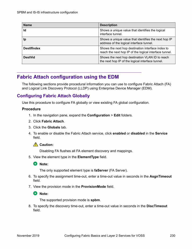
Name DescriptionId Shows a unique value that identifies the logical
interface tunnel.Ip Shows a unique value that identifies the next hop IP
address of the logical interface tunnel.DestIfIndex Shows the next hop destination interface index to
reach the next hop IP of the logical interface tunnel.DestVid Shows the next hop destination VLAN ID to reach
the next hop IP of the logical interface tunnel.
Fabric Attach configuration using the EDMThe following sections provide procedural information you can use to configure Fabric Attach (FA)and Logical Link Discovery Protocol (LLDP) using Enterprise Device Manager (EDM).
Configuring Fabric Attach GloballyUse this procedure to configure FA globally or view existing FA global configuration.
Procedure1. In the navigation pane, expand the Configuration > Edit folders.
2. Click Fabric Attach.
3. Click the Globals tab.
4. To enable or disable the Fabric Attach service, click enabled or disabled in the Servicefield.
Caution:
Disabling FA flushes all FA element discovery and mappings.
5. View the element type in the ElementType field.
Note:
The only supported element type is faServer (FA Server).
6. To specify the assignment time-out, enter a time-out value in seconds in the AsgnTimeoutfield.
7. View the provision mode in the ProvisionMode field.
Note:
The supported provision mode is spbm.
8. To specify the discovery time-out, enter a time-out value in seconds in the DiscTimeoutfield.
SPBM and IS-IS infrastructure configuration
November 2019 Configuring Fabric Basics and Layer 2 Services for VOSS 230
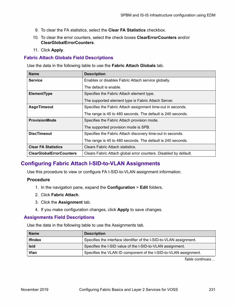
9. To clear the FA statistics, select the Clear FA Statistics checkbox.
10. To clear the error counters, select the check boxes ClearErrorCounters and/orClearGlobalErrorCounters.
11. Click Apply.
Fabric Attach Globals Field DescriptionsUse the data in the following table to use the Fabric Attach Globals tab.
Name DescriptionService Enables or disables Fabric Attach service globally.
The default is enable.ElementType Specifies the Fabric Attach element type.
The supported element type is Fabric Attach Server.AsgnTimeout Specifies the Fabric Attach assignment time-out in seconds.
The range is 45 to 480 seconds. The default is 240 seconds.ProvisionMode Specifies the Fabric Attach provision mode.
The supported provision mode is SPB.DiscTimeout Specifies the Fabric Attach discovery time-out in seconds.
The range is 45 to 480 seconds. The default is 240 seconds.Clear FA Statistics Clears Fabric Attach statistics.ClearGlobalErrorCounters Clears Fabric Attach global error counters. Disabled by default.
Configuring Fabric Attach I-SID-to-VLAN AssignmentsUse this procedure to view or configure FA I-SID-to-VLAN assignment information.
Procedure1. In the navigation pane, expand the Configuration > Edit folders.
2. Click Fabric Attach.
3. Click the Assignment tab.
4. If you make configuration changes, click Apply to save changes.
Assignments Field DescriptionsUse the data in the following table to use the Assignments tab.
Name DescriptionIfIndex Specifies the interface identifier of the I-SID-to-VLAN assignment.Isid Specifies the I-SID value of the I-SID-to-VLAN assignment.Vlan Specifies the VLAN ID component of the I-SID-to-VLAN assignment.
Table continues…
SPBM and IS-IS infrastructure configuration using EDM
November 2019 Configuring Fabric Basics and Layer 2 Services for VOSS 231
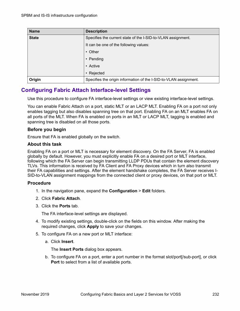
Name DescriptionState Specifies the current state of the I-SID-to-VLAN assignment.
It can be one of the following values:
• Other
• Pending
• Active
• RejectedOrigin Specifies the origin information of the I-SID-to-VLAN assignment.
Configuring Fabric Attach Interface-level SettingsUse this procedure to configure FA interface-level settings or view existing interface-level settings.
You can enable Fabric Attach on a port, static MLT or an LACP MLT. Enabling FA on a port not onlyenables tagging but also disables spanning tree on that port. Enabling FA on an MLT enables FA onall ports of the MLT. When FA is enabled on ports in an MLT or LACP MLT, tagging is enabled andspanning tree is disabled on all those ports.
Before you beginEnsure that FA is enabled globally on the switch.
About this taskEnabling FA on a port or MLT is necessary for element discovery. On the FA Server, FA is enabledglobally by default. However, you must explicitly enable FA on a desired port or MLT interface,following which the FA Server can begin transmitting LLDP PDUs that contain the element discoveryTLVs. This information is received by FA Client and FA Proxy devices which in turn also transmittheir FA capabilities and settings. After the element handshake completes, the FA Server receives I-SID-to-VLAN assignment mappings from the connected client or proxy devices, on that port or MLT.
Procedure1. In the navigation pane, expand the Configuration > Edit folders.
2. Click Fabric Attach.
3. Click the Ports tab.
The FA interface-level settings are displayed.
4. To modify existing settings, double-click on the fields on this window. After making therequired changes, click Apply to save your changes.
5. To configure FA on a new port or MLT interface:
a. Click Insert.
The Insert Ports dialog box appears.
b. To configure FA on a port, enter a port number in the format slot/port[/sub-port], or clickPort to select from a list of available ports.
SPBM and IS-IS infrastructure configuration
November 2019 Configuring Fabric Basics and Layer 2 Services for VOSS 232

c. To configure FA on an MLT, enter an MLT ID or click Mlt to select from a list ofconfigured MLTs.
Note:
FA is successfully enabled on the MLT, only if all ports of the MLT have FAsuccessfully enabled. Enabling FA enables LLDP on all ports. Tagging is enabledand spanning tree is disabled.
d. Click Insert to save your changes.
6. To remove (delete) FA on a port or MLT:
a. In the content pane, select a port or MLT from the list.
b. Click Delete.
Caution:
Removing FA on an interface flushes all FA element discovery and I-SID-to-VLANmappings associated with that interface.
Ports Field DescriptionsUse the data in the following table to use the Ports tab.
Name DescriptionIfIndex Specifies the interface (port or MLT) on which Fabric Attach is configured.State Specifies the current state of the Fabric Attach port. It is either enabled or
disabled.
This field indicates whether LLDP PDUs (that include FA TLVs) aregenerated on the port (enabled) or not (disabled).
MsgAuthStatus Specifies the Fabric Attach message authentication status on the port. It iseither enabled or disabled.
MsgAuthKey Specifies the Fabric Attach message authentication key for the associatedport.
The maximum length of this key is 32 characters.MgmtIsid Specifies the Fabric Attach management I-SID for the associated port. The
range is 0 to 16777215.
A zero value indicates that the management I-SID is not specified for theinterface.
MgmtCvid Specifies the Fabric Attach management customer VLAN ID (C-VID) for theinterface.
A zero value indicates that no C-VID is specified for the interface. Using themaximum configuration value for your switch indicates the port is untagged.Platform support determines the C-VID range.
Viewing Fabric Attach discovered elementsUse this procedure to view discovered Fabric Attach elements.
SPBM and IS-IS infrastructure configuration using EDM
November 2019 Configuring Fabric Basics and Layer 2 Services for VOSS 233

About this taskWhen FA is enabled on an FA Server switch, LLDP PDUs are exchanged between the FA Serverand FA Clients or Proxies. Standard LLDPs allow neighbors to be learned. In addition,organizational specific element discovery TLVs allow the Client or Proxy to recognize that it hasattached to an FA Server. Only after the discovery handshake is complete, an FA Client or Proxycan transmit I-SID-to-VLAN assignments to join the SPB Fabric through the FA Server.
Procedure1. In the navigation pane, expand the Configuration > Edit folders.
2. Click Fabric Attach.
3. In the content pane, click the Elements tab.
Elements field descriptionsUse the data in the following table to use the Elements tab.
Name DescriptionIfIndex Specifies the interface (port or MLT) at which the Fabric Attach element was
discovered.ElementType Specifies the element type of the discovered Fabric Attach element, as
advertised using LLDP.
The supported element type is the Fabric Attach Server.ElementVlan Specifies the VLAN ID of the discovered Fabric Attach element, as
advertised using LLDP.ElementId Specifies the system ID of the discovered Fabric Attach element, as
advertised using LLDP.ElementState Specifies the state flag data associated with the discovered Fabric Attach
element, as advertised using LLDP.ElementOperAuthStatus Specifies the authentication status of the discovered Fabric Attach element.ElementAsgnsOperAuthStatus
Specifies the authentication status of remote assignments.
ElementAuth Specifies the discovered element authentication status.AsgnsAuth Specifies the assignment authentication status.
Viewing FA statisticsUse this procedure to view FA statistics.
Procedure1. In the navigation pane, expand the Configuration > Edit folders.
2. Click Fabric Attach.
3. In the content pane, click the Stats tab.
SPBM and IS-IS infrastructure configuration
November 2019 Configuring Fabric Basics and Layer 2 Services for VOSS 234
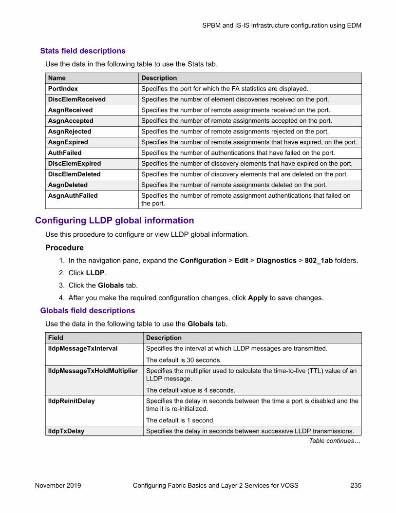
Stats field descriptionsUse the data in the following table to use the Stats tab.
Name DescriptionPortIndex Specifies the port for which the FA statistics are displayed.DiscElemReceived Specifies the number of element discoveries received on the port.AsgnReceived Specifies the number of remote assignments received on the port.AsgnAccepted Specifies the number of remote assignments accepted on the port.AsgnRejected Specifies the number of remote assignments rejected on the port.AsgnExpired Specifies the number of remote assignments that have expired, on the port.AuthFailed Specifies the number of authentications that have failed on the port.DiscElemExpired Specifies the number of discovery elements that have expired on the port.DiscElemDeleted Specifies the number of discovery elements that are deleted on the port.AsgnDeleted Specifies the number of remote assignments deleted on the port.AsgnAuthFailed Specifies the number of remote assignment authentications that failed on
the port.
Configuring LLDP global informationUse this procedure to configure or view LLDP global information.
Procedure1. In the navigation pane, expand the Configuration > Edit > Diagnostics > 802_1ab folders.
2. Click LLDP.
3. Click the Globals tab.
4. After you make the required configuration changes, click Apply to save changes.
Globals field descriptionsUse the data in the following table to use the Globals tab.
Field DescriptionlldpMessageTxInterval Specifies the interval at which LLDP messages are transmitted.
The default is 30 seconds.lldpMessageTxHoldMultiplier Specifies the multiplier used to calculate the time-to-live (TTL) value of an
LLDP message.
The default value is 4 seconds.lldpReinitDelay Specifies the delay in seconds between the time a port is disabled and the
time it is re-initialized.
The default is 1 second.lldpTxDelay Specifies the delay in seconds between successive LLDP transmissions.
Table continues…
SPBM and IS-IS infrastructure configuration using EDM
November 2019 Configuring Fabric Basics and Layer 2 Services for VOSS 235

Field DescriptionThe default is 1 second.
The recommended value is as follows:
1 < lldpTxDelay < (0.25 x lldpMessageTxInterval)lldpNotificationInterval Specifies the time interval between successive LLDP notifications. It
controls the transmission of notifications.
The default is 5 seconds.StatsRemTablesLastChangeTime Specifies the timestamp of LLDP missed notification events on a port, for
example, due to transmission loss.RemTablesInserts Specifies the number of times the information advertised by a MAC
Service Access Point (MSAP) is inserted into the respective tables.RemTablesDeletes Specifies the number of times the information advertised by an MSAP is
deleted from the respective tables.RemTablesDrops Specifies the number of times the information advertised by an MSAP
was not entered into the respective tables.RemTablesAgeouts Specifies the number of times the information advertised by an MSAP
was deleted from the respective tables.
Viewing the LLDP port informationUse this procedure to view the LLDP port information.
Procedure1. In the navigation pane, expand the Configuration > Edit > Diagnostics > 802_1ab folders.
2. Click LLDP.
3. Click the Port tab.
4. View the administrative status of the port in the AdminStatus field. To modify, double-clickon a cell and select a value from the drop-down list.
5. View whether the port is enabled for notifications in the NotificationEnable field. To modify,double-click on a cell and select a value from the drop-down list.
6. View the set of TLVs whose transmission using LLDP is always allowed by networkmanagement in the TLVsTxEnable field.
7. (Optional) Modify the TLVs as follows:
a. To enable a TLV, select the appropriate check box, and click Ok. You can select morethan one check box.
b. To enable all TLVs, click Select All, and click Ok.
c. To disable all TLVs, click Disable All, and click Ok.
8. View the CDP administrative status in the CdpAdminState field. To modify, double-click on acell and select a value from the drop-down list.
SPBM and IS-IS infrastructure configuration
November 2019 Configuring Fabric Basics and Layer 2 Services for VOSS 236

9. Click Apply to save any configuration changes.
10. Click Refresh to verify the configuration.
Port Field DescriptionsUse the data in the following table to use the Port tab.
Name DescriptionPortNum Specifies the port number. This is a read-only cell.AdminStatus Specifies the administrative status of the port. The options are:
• txOnly: LLDP frames are only transmitted on this port.
• rxOnly: LLDP frames are only received on this port.
• txAndRx: LLDP frames are transmitted and received on this port.
• disabled: LLDP frames are neither transmitted or received on this port.Any information received on this port from remote systems before this isdisabled, ages out.
The default is disabled.NotificationEnable Specifies whether the port is enabled or disabled for notifications.
• true: indicates that the notifications are enabled.
• false: indicates that the notifications are disabled.
The default is false.TLVsTxEnable Specifies the set of TLVs whose transmission using LLDP is always allowed
by network management.
The following list describes the TLV types:
• portDesc — indicates that the Port Description TLV is transmitted.
• sysName — indicates that the System Name TLV. is transmitted.
• sysDesc — indicates that the System Description TLV. is transmitted.
• sysCap — indicates that the System Capabilities TLV. is transmitted.
The default is an empty set of TLVs.CdpAdminState Specifies the CDP administrative status of the port. Configure this field to
true to enable the Industry Standard Discovery Protocol (ISDP) on a port.ISDP is CDP-compatible.
• true: indicates CDP is enabled.
• false: indicates CDP is disabled.
The default is false.
If CDP is enabled, the interface accepts only CDP packets. Similarly, if CDPis disabled but LLDP is enabled, the interface accepts only LLDP packets.To switch a port from CDP mode to LLDP mode, the LLDP status on thatport must be txAndRx.
SPBM and IS-IS infrastructure configuration using EDM
November 2019 Configuring Fabric Basics and Layer 2 Services for VOSS 237

Viewing LLDP Transmission StatisticsUse this procedure to view the LLDP transmission statistics. You can also view the statisticsgraphically.
About this taskLLDP operates at the port interface level. Enabling FA on a port automatically enables LLDPtransmission and reception on that port. It also enables traffic tagging and disables spanning tree onthat port.Enabling FA on an MLT enables LLDP transmission and reception on all ports in that MLT.
Note:When a port is removed from an MLT, LLDP transmission on that port stops and spanning treeis enabled. Any I-SID-to-VLAN mappings on that port are removed, if not already learned on anyother port in the MLT. This also causes the Switched UNI I-SID to be deleted from the MLT. Ifhowever, the mappings are learned on another port on the MLT, then the Switched UNI I-SIDcontinues to exist for that MLT.For ports in an LACP MLT, when FA is enabled, tagging is enabled on all ports in the LACP MLT.The consistency check for FA is based on key membership. If all ports with the same key do notsupport FA, FA is not successfully enabled on those ports.
Note:If a slot is removed from the switch chassis, the statistics are not displayed on the slot ports.When the slot is inserted back again, the statistics counters are reset.
Procedure1. In the navigation pane, expand the Configuration > Edit > Diagnostics > 802_1ab folders.
2. Click LLDP.
3. Click the TX Stats tab.
The transmission statistics are displayed.
4. To view the transmission statistics graphically for a port:
a. In the content pane (on the right-hand-side), select a row and click the Graph button.
The TX Stats-Graph,<port-number> tab displays.
You can view a graphical representation of the LLDP frames transmitted (FramesTotal),for the following parameters:
• AbsoluteValue
• Cumulative
• Average/sec
• Minimum/sec
• Maximum/sec
• LastVal/sec
SPBM and IS-IS infrastructure configuration
November 2019 Configuring Fabric Basics and Layer 2 Services for VOSS 238
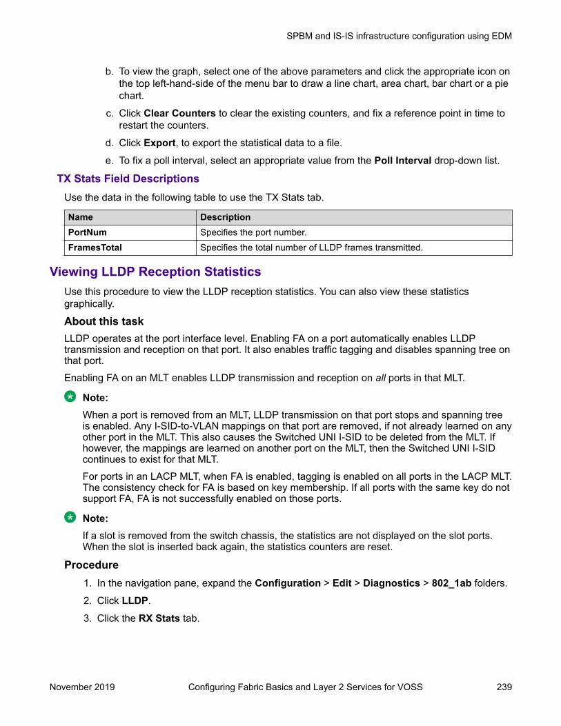
b. To view the graph, select one of the above parameters and click the appropriate icon onthe top left-hand-side of the menu bar to draw a line chart, area chart, bar chart or a piechart.
c. Click Clear Counters to clear the existing counters, and fix a reference point in time torestart the counters.
d. Click Export, to export the statistical data to a file.
e. To fix a poll interval, select an appropriate value from the Poll Interval drop-down list.
TX Stats Field DescriptionsUse the data in the following table to use the TX Stats tab.
Name DescriptionPortNum Specifies the port number.FramesTotal Specifies the total number of LLDP frames transmitted.
Viewing LLDP Reception StatisticsUse this procedure to view the LLDP reception statistics. You can also view these statisticsgraphically.
About this taskLLDP operates at the port interface level. Enabling FA on a port automatically enables LLDPtransmission and reception on that port. It also enables traffic tagging and disables spanning tree onthat port.Enabling FA on an MLT enables LLDP transmission and reception on all ports in that MLT.
Note:When a port is removed from an MLT, LLDP transmission on that port stops and spanning treeis enabled. Any I-SID-to-VLAN mappings on that port are removed, if not already learned on anyother port in the MLT. This also causes the Switched UNI I-SID to be deleted from the MLT. Ifhowever, the mappings are learned on another port on the MLT, then the Switched UNI I-SIDcontinues to exist for that MLT.For ports in an LACP MLT, when FA is enabled, tagging is enabled on all ports in the LACP MLT.The consistency check for FA is based on key membership. If all ports with the same key do notsupport FA, FA is not successfully enabled on those ports.
Note:If a slot is removed from the switch chassis, the statistics are not displayed on the slot ports.When the slot is inserted back again, the statistics counters are reset.
Procedure1. In the navigation pane, expand the Configuration > Edit > Diagnostics > 802_1ab folders.
2. Click LLDP.
3. Click the RX Stats tab.
SPBM and IS-IS infrastructure configuration using EDM
November 2019 Configuring Fabric Basics and Layer 2 Services for VOSS 239

4. To view the reception statistics graphically for a port:
a. Select a row and click Graph.
The RX Stats-Graph,<port-number> tab displays.
You can view a graphical representation of the following data:
• FramesDiscardedTotal — Total number of LLDP received frames that werediscarded.
• FramesErrors — Total number of erroneous LLDP frames received.
• FramesTotal — Total number of frames received.
• TLVsDiscardedTotal — Total number of received TLVs that were discarded.
• TLVsUnrecognizedTotal — Total number of unrecognized TLVs received.
b. Select one of the above parameters and click the appropriate icon on the top left-hand-side corner of the menu bar to draw a line chart, area chart, bar chart or a pie chart.
c. Click Clear Counters to clear the existing counters, and fix a reference point in time torestart the counters.
d. Click Export, to export the statistical data to a file.
e. To fix a poll interval, select an appropriate value from the Poll Interval drop-down list.
RX Stats Field DescriptionsUse the data in the following table to use the RX Stats tab.
Name DescriptionPortNum Specifies the port number.FramesDiscardedTotal Specifies the number of LLDP frames received on the port, but discarded,
for any reason.
This counter provides an indication of possible LLDP header formattingproblems in the sending system, or LLDP PDU validation problems in thereceiving system.
FramesErrors Specifies the number of invalid LLDP frames received on the port.FramesTotal Specifies the total number of LLDP frames received on the port.TLVsDiscardedTotal Specifies the number of LLDP TLVs discarded on the port, for any reason.TLVsUnrecognizedTotal Specifies the number of LLDP TLVs on the port, that are unrecognized on
that port.
An unrecognized TLV is referred to as the TLV whose type value is in therange of reserved TLV types (000 1001–111 1110). An unrecognized TLVcould be, for example, a basic management TLV from a later LLDP version.
AgeoutsTotal Specifies the number of LLDP age-outs that occur on a specific port.
An age-out is the number of times the complete set of informationadvertised by a particular MSAP is deleted, because the informationtimeliness interval has expired.
SPBM and IS-IS infrastructure configuration
November 2019 Configuring Fabric Basics and Layer 2 Services for VOSS 240

Viewing LLDP local system informationUse this procedure to view the LLDP local system information.
Procedure1. In the navigation pane, expand the Configuration > Edit > Diagnostics > 802_1ab folders.
2. Click LLDP.
3. Click the Local System tab.
Local System field descriptionsUse the data in the following table to use the Local System tab.
Name DescriptionChassisIdSubType Indicates the encoding used to identify the local system chassis.
• chassisComponent
• interfaceAlias
• portComponent
• macAddress
• networkAddress
• interfaceName
• localChassisId Indicates the chassis ID of the local system.SysName Indicates local system name.SysDesc Indicates local system description.SysCapSupported Indicates the system capabilities supported on the local system.SysCapEnabled Indicates the system capabilities that are enabled on the local system.
Viewing LLDP local port informationUse this procedure to view the LLDP local port information.
Procedure1. In the navigation pane, expand the Configuration > Edit > Diagnostics > 802_1ab folders.
2. Click LLDP.
3. Click the Local Port tab.
Local port field descriptionsUse the data in the following table to use the Local Port tab.
SPBM and IS-IS infrastructure configuration using EDM
November 2019 Configuring Fabric Basics and Layer 2 Services for VOSS 241

Name DescriptionPortNum Indicates the port number.PortIdSubType Indicates the type of port identifier.
• interfaceAlias
• portComponent
• macAddress
• networkAddress
• interfaceName
• agentCircuitId
• localPortId Indicates the identifier associated with the port, on the local system.PortDesc Indicates the description of the port, on the local system.
Viewing LLDP Neighbor InformationUse this procedure to view the LLDP neighbor information.
Procedure1. In the navigation pane, expand the Configuration > Edit > Diagnostics > 802_1ab folders.
2. Click LLDP.
3. Click the Neighbor tab.
Neighbor Field DescriptionsUse the data in the following table to use the Neighbor tab.
Name DescriptionTimeMark Indicates the time filter. For more information about TimeFilter, see the
TimeFilter textual convention in IETF RFC 2021.LocalPortNum Identifies the port on which the remote system information is received.Index Indicates a particular connection instance that is unique to the remote
system.ProtocolType Indicates whether the entry protocol is CDP or LLDP.SysName Indicates the name of the remote system.IpAddress Indicates the neighbor’s IP address.PortIdSubType Indicates the type of encoding used to identify the remote port.PortId Indicates the remote port ID.PortDesc Indicates the remote port description.ChassisIdSubtype Indicates the type of encoding used to identify the remote system chassis.
• chassisComponentTable continues…
SPBM and IS-IS infrastructure configuration
November 2019 Configuring Fabric Basics and Layer 2 Services for VOSS 242

Name Description• interfaceAlias
• portComponent
• macAddress
• networkAddress
• interfaceName
• localChassisId Indicates the chassis ID of the remote system.SysCapSupported Identifies the system capabilities supported on the remote system.SysCapEnabled Identifies the system capabilities enabled on the remote system.SysDesc Indicates the description of the remote system.
Viewing Global FA Statistics GraphicallyUse this procedure to view the global FA statistics graphically.
Procedure1. In the navigation pane, expand the Configuration > Graph folders.
2. Click Chassis.
3. Click the Fabric Attach tab.
4. To view a graphical representation of the statistics, select a row and click the appropriateicon on the top left-hand-side of the menu bar to draw a line chart, area chart, bar chart or apie chart.
5. Click Clear Counters to clear the existing counters, and fix a reference point in time torestart the counters.
6. Click Export, to export the statistical data to a file.
7. To fix a poll interval, select an appropriate value from the Poll Interval drop-down list.
Fabric Attach field descriptionsUse the data in the following table to use the Fabric Attach tab.
Name DescriptionDiscElemReceived Specifies the number of discovery elements received
globally.AsgnReceived Specifies the number of remote I-SID-to-VLAN
assignments received globally.AsgnAccepted Specifies the number of remote I-SID-to-VLAN
assignments accepted globally.
Table continues…
SPBM and IS-IS infrastructure configuration using EDM
November 2019 Configuring Fabric Basics and Layer 2 Services for VOSS 243

Name DescriptionAsgnRejected Specifies the number of remote I-SID-to-VLAN
assignments rejected globally.AsgnExpired Specifies the number of remote I-SID-to-VLAN
assignments that expired globally.AuthFailed Specifies the number of authentications that failed
globally.DiscAuthFailed Specifies the number of discovery authentications
that failed globally.DiscElemExpired Specifies the number of discovery elements that
expired globally.DiscElemDeleted Specifies the number of discovery elements that
were deleted globally.AsgnDeleted Specifies the number of remote assignments that
were deleted globally.
Viewing FA Port Statistics GraphicallyUse this procedure to view the FA port statistics graphically.
Before you beginEnsure that a switch port is selected in the Device Physical View tab.
Procedure1. In the navigation pane, expand the Graph > Port folders.
2. Click the Fabric Attach tab.
The FA port statistics are displayed.
3. To view a graphical representation of the port statistics, select a row and click theappropriate icon on the top left-hand-side of the menu bar to draw a line chart, area chart,bar chart or a pie chart.
4. Click Clear Counters to clear the existing counters, and fix a reference point in time torestart the counters.
5. Click Export, to export the statistical data to a file.
6. To fix a poll interval, select an appropriate value from the Poll Interval drop-down list.
Fabric Attach Field DescriptionsUse the data in the following table to use the Fabric Attach tab.
Name DescriptionDiscElemReceived Specifies the number of discovery elements received on a given port.AsgnReceived Specifies the number of remote I-SID-to-VLAN assignments received on a
given port.Table continues…
SPBM and IS-IS infrastructure configuration
November 2019 Configuring Fabric Basics and Layer 2 Services for VOSS 244

Name DescriptionAsgnAccepted Specifies the number of remote I-SID-to-VLAN assignments accepted on a
given port.AsgnRejected Specifies the number of remote I-SID-to-VLAN assignments rejected on a
given port.AsgnExpired Specifies the number of remote I-SID-to-VLAN assignments that expired on
a given port.AuthFailed Indicates the number of received TLVs for which authentication was
attempted and failed on the identified port.DiscElemExpired Specifies the number of discovery elements that expired on a given port.DiscElemDeleted Specifies the number of discovery elements that were deleted on a given
port.AsgnDeleted Specifies the number of remote assignments that were deleted on a given
port.AsgnAuthFailed Specifies the number of remote assignment authentications that failed on a
given port.
Inserting a Zero Touch ClientUse this procedure to insert a FA Zero Touch Client.
Procedure1. In the navigation pane, expand the Configuration > Edit folders.
2. Click Fabric Attach.
3. Click the Zero Touch Client Auto Attach tab.
4. Click Insert.
The Insert Zero Touch Client dialog box appears.
5. In the Type field click the ellipsis and select a client. Click Ok to select the client or Refreshto update the list.
6. In the Isid field enter the ISID value.
The ISID value is between 0 and 16777214.
7. Click Insert.
Configuring FA Zero Touch Client auto attachUse this procedure to configure FA Zero Touch Client auto attach.
Procedure1. In the navigation pane, expand the Configuration > Edit folders.
2. Click Fabric Attach3. Click the Zero Touch Client Auto Attach tab.
SPBM and IS-IS infrastructure configuration using EDM
November 2019 Configuring Fabric Basics and Layer 2 Services for VOSS 245

From the Zero Touch Client Auto Attach tab you can configure a number of auto attachsettings.
4. Click Insert.5. In the Type field click the ellipsis and select a client.
6. Click Ok to select the client or Refresh to update the list.
7. In the Isid field enter the ISID value.
8. Click Insert.9. (Optional) To Delete a FA Zero Touch client select it from the auto attach table and click
Delete.
Zero Touch Client Auto Attach Field DescriptionsUse the data in the following table to use the Zero Touch Client Auto Attach tab
Field DescriptionType This column describes the type of client assigned to
auto attach. Available FA client types are:
• Wireless AP (Type 1)
• Wireless AP (Type 2)
• Switch
• Router
• IP Phone
• IP Camera
• IP Video
• Security Device
• Virtual Switch
• Server Endpoint
• ONA (SDN)
• ONA (spb0IP)Vlan Specifies the VLAN ID component of the I-SID-to-
VLAN assignment.Isid Specifies the I-SID value of the I-SID-to-VLAN
assignment.
SPBM and IS-IS infrastructure configuration
November 2019 Configuring Fabric Basics and Layer 2 Services for VOSS 246
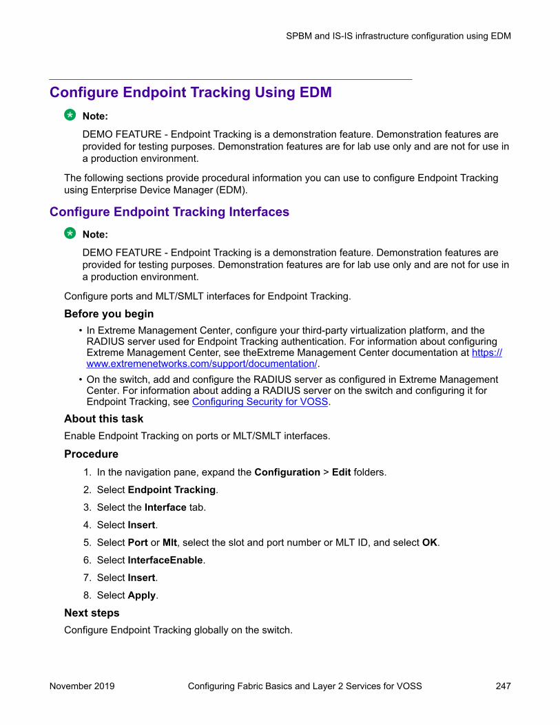
Configure Endpoint Tracking Using EDMNote:
DEMO FEATURE - Endpoint Tracking is a demonstration feature. Demonstration features areprovided for testing purposes. Demonstration features are for lab use only and are not for use ina production environment.
The following sections provide procedural information you can use to configure Endpoint Trackingusing Enterprise Device Manager (EDM).
Configure Endpoint Tracking InterfacesNote:
DEMO FEATURE - Endpoint Tracking is a demonstration feature. Demonstration features areprovided for testing purposes. Demonstration features are for lab use only and are not for use ina production environment.
Configure ports and MLT/SMLT interfaces for Endpoint Tracking.
Before you begin• In Extreme Management Center, configure your third-party virtualization platform, and the
RADIUS server used for Endpoint Tracking authentication. For information about configuringExtreme Management Center, see theExtreme Management Center documentation at https://www.extremenetworks.com/support/documentation/.
• On the switch, add and configure the RADIUS server as configured in Extreme ManagementCenter. For information about adding a RADIUS server on the switch and configuring it forEndpoint Tracking, see Configuring Security for VOSS.
About this taskEnable Endpoint Tracking on ports or MLT/SMLT interfaces.
Procedure1. In the navigation pane, expand the Configuration > Edit folders.
2. Select Endpoint Tracking.
3. Select the Interface tab.
4. Select Insert.5. Select Port or Mlt, select the slot and port number or MLT ID, and select OK.
6. Select InterfaceEnable.
7. Select Insert.8. Select Apply.
Next stepsConfigure Endpoint Tracking globally on the switch.
SPBM and IS-IS infrastructure configuration using EDM
November 2019 Configuring Fabric Basics and Layer 2 Services for VOSS 247

Interface Field DescriptionsUse the data in the following table to use the Interfaces tab.
Name DescriptionInterfaceIndex Specifies the interface index of the selected port or
MLT.InterfaceEnable Enables Endpoint Tracking on the selected port or
MLT.
Configure Endpoint Tracking GloballyNote:
DEMO FEATURE - Endpoint Tracking is a demonstration feature. Demonstration features areprovided for testing purposes. Demonstration features are for lab use only and are not for use ina production environment.
Configure Endpoint Tracking globally on the switch.
Before you begin• In Extreme Management Center, configure your third-party virtualization platform, and the
RADIUS server used for Endpoint Tracking authentication. For information about configuringExtreme Management Center, see the Extreme Management Center documentation at https://www.extremenetworks.com/support/documentation/.
• On the switch, add and configure the RADIUS server as configured in Extreme ManagementCenter. For information about adding a RADIUS server on the switch and configuring it forEndpoint Tracking, see Configuring Security for VOSS.
• Create and enable Endpoint Tracking on interfaces.
About this taskOptionally, if the RADIUS outbound attributes do not include an I-SID value, configure an I-SIDoffset value, and globally enable I-SID offset for Endpoint Tracking. The I-SID offset value is used tocalculate an I-SID value for a switched UNI if no I-SID value is provided by the RADIUS server. Inthat case, the I-SID value is calculated as follows: I-SID = VLAN ID + configured I-SID offset value.After optionally configuring an I-SID offset value, enable Endpoint Tracking globally on the switch.
Note:If you have previously enabled Endpoint Tracking globally and want to change the currentlyconfigured I-SID offset value, you must disable Endpoint Tracking globally, change the I-SIDvalue, and then re-enable Endpoint Tracking globally.
Procedure1. In the navigation pane, expand the Configuration > Edit folders.
2. Select Endpoint Tracking.
3. Select the Globals tab.
4. (Optional) Configure an I-SID offset value, and enable I-SID offset globally on the switch:
SPBM and IS-IS infrastructure configuration
November 2019 Configuring Fabric Basics and Layer 2 Services for VOSS 248

Enter a value into the AutoIsidOffset field and select AutoIsidOffsetEnable.
5. Select GlobalEnable.
6. Select Apply.
Globals Field DescriptionsUse the data in the following table to use the Globals tab.
Name DescriptionAutoIsidOffset The I-SID offset value. The default is 15990000.AutoIsidOffsetEnable Enables or disables I-SID offset value globally on the
switch. The default is disabled.GlobalEnable Enables or disables Endpoint Tracking globally on
the switch. The default is disabled.VisibilityEnable Enables or disables visibility mode for Endpoint
Tracking. The default is disabled.
Display Binding InformationNote:
DEMO FEATURE - Endpoint Tracking is a demonstration feature. Demonstration features areprovided for testing purposes. Demonstration features are for lab use only and are not for use ina production environment.
Display Endpoint Tracking binding information.
About this taskDisplay all VLAN:I-SID binding information on the switch for Endpoint Tracking.
Procedure1. In the navigation pane, expand the Configuration > Edit folders.
2. Select Endpoint Tracking.
3. Select the Binding tab.
Binding Field DescriptionsUse the data in the following table to use the Binding tab.
Name DescriptionIfIndex Specifies the interface index of the selected port or
MLT.MacAddress Specifies the MAC address that corresponds to the
VLAN:I-SID binding.
Table continues…
SPBM and IS-IS infrastructure configuration using EDM
November 2019 Configuring Fabric Basics and Layer 2 Services for VOSS 249
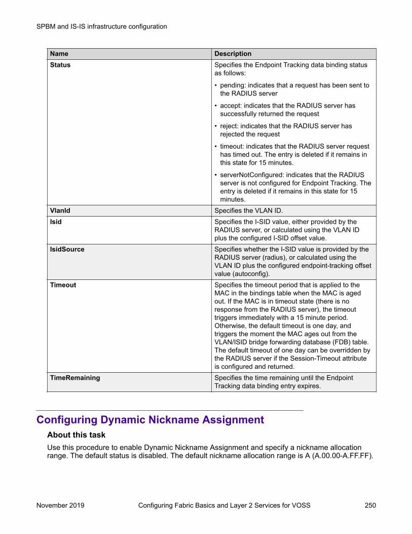
Name DescriptionStatus Specifies the Endpoint Tracking data binding status
as follows:
• pending: indicates that a request has been sent tothe RADIUS server
• accept: indicates that the RADIUS server hassuccessfully returned the request
• reject: indicates that the RADIUS server hasrejected the request
• timeout: indicates that the RADIUS server requesthas timed out. The entry is deleted if it remains inthis state for 15 minutes.
• serverNotConfigured: indicates that the RADIUSserver is not configured for Endpoint Tracking. Theentry is deleted if it remains in this state for 15minutes.
VlanId Specifies the VLAN ID.Isid Specifies the I-SID value, either provided by the
RADIUS server, or calculated using the VLAN IDplus the configured I-SID offset value.
IsidSource Specifies whether the I-SID value is provided by theRADIUS server (radius), or calculated using theVLAN ID plus the configured endpoint-tracking offsetvalue (autoconfig).
Timeout Specifies the timeout period that is applied to theMAC in the bindings table when the MAC is agedout. If the MAC is in timeout state (there is noresponse from the RADIUS server), the timeouttriggers immediately with a 15 minute period.Otherwise, the default timeout is one day, andtriggers the moment the MAC ages out from theVLAN/ISID bridge forwarding database (FDB) table.The default timeout of one day can be overridden bythe RADIUS server if the Session-Timeout attributeis configured and returned.
TimeRemaining Specifies the time remaining until the EndpointTracking data binding entry expires.
Configuring Dynamic Nickname AssignmentAbout this taskUse this procedure to enable Dynamic Nickname Assignment and specify a nickname allocationrange. The default status is disabled. The default nickname allocation range is A (A.00.00-A.FF.FF).
SPBM and IS-IS infrastructure configuration
November 2019 Configuring Fabric Basics and Layer 2 Services for VOSS 250

Note:You must disable Dynamic Nickname Assignment before you can change the nicknameallocation range.
Procedure1. In the navigation pane, expand the Configuration > IS-IS folders.
2. Click SPBM.
3. Click the Globals tab.
4. To enable the Nick-name server, click enable in the NicknameServerEnable field.
5. In the NicknameServerRange field, select the nickname server allocation range.
Globals field descriptionsUse the data in the following table to use the Globals tab.
Name DescriptionGlobalEnable Enables or disables SPBM globally. The default is
disabled.GlobalEtherType Specifies the global ethertype value as 0x8100 or
0x88a8. The default value is 0x8100.NicknameServerEnable Enables or disables the nickname server. The default
is disabled.NicknameDynamicAllocationStatus Displays the Dynamic Nickname Allocation service
operational status. This value is read-only.NicknameServerRange Specifies the nickname allocation range for Dynamic
Nickname Assignment. The default is rangeA (A.00.00 to A.FF.FF).
SPBM configuration examplesThis section provides configuration examples to configure basic SPBM and IS-IS infrastructure.
Examples and network illustrations in this document may illustrate only one of the supportedplatforms. Unless otherwise noted, the concept illustrated applies to all supported platforms.
Basic SPBM configuration exampleThe following figure shows a sample greenfield deployment for SPBM.Figure 25: Greenfield SPBM deployment
SPBM configuration examples
November 2019 Configuring Fabric Basics and Layer 2 Services for VOSS 251

Note:For migration purposes, SPBM can coexist with existing SMLT configurations.
Ethernet and MLT configurationThe following sections show the steps required to configure the Ethernet and MLT interfaces in thisexample.
SwitchCPORT CONFIGURATION - PHASE 1
interface GigabitEthernet 1/30encapsulation dot1qexit
SwitchGPORT CONFIGURATION - PHASE 1
interface GigabitEthernet 1/5encapsulation dot1qexit
MLT CONFIGURATION
mlt 1 enablemlt 1 member 1/21-1/22mlt 1 encapsulation dot1q
SwitchDMLT CONFIGURATION
mlt 1 enablemlt 1 member 1/20,1/30mlt 1 encapsulation dot1q
IS-IS SPBM global configurationThe following figure shows the IS-IS area information added to the network.
SPBM and IS-IS infrastructure configuration
November 2019 Configuring Fabric Basics and Layer 2 Services for VOSS 252

Figure 26: IS-IS SPBM globalThe following sections show the steps required to configure the global IS-IS SPBM parameters inthis example.
SwitchCenableconfigure terminalprompt SwitchC
BOOT CONFIGURATION
spbmspbm ethertype 0x8100
ISIS SPBM CONFIGURATION
router isisspbm 1spbm 1 nick-name f.30.13spbm 1 b-vid 20
ISIS CONFIGURATION
is-type l1manual-area 30.0000sys-name SwitchCexitrouter isis enable
VLAN CONFIGURATION
vlan create 20 name "B-VLAN" type spbm-bvlan
SwitchGenableconfigure terminalprompt SwitchG
BOOT CONFIGURATION
spbmspbm ethertype 0x8100
ISIS SPBM CONFIGURATION
router isisspbm 1spbm 1 nick-name f.30.10
SPBM configuration examples
November 2019 Configuring Fabric Basics and Layer 2 Services for VOSS 253

spbm 1 b-vid 20
ISIS CONFIGURATION
is-type l1manual-area 30.0000sys-name SwitchGexitrouter isis enable
VLAN CONFIGURATION
vlan create 20 name "B-VLAN" type spbm-bvlan
SwitchDenableconfigure terminalprompt SwitchD
BOOT CONFIGURATION
spbmspbm ethertype 0x8100
ISIS SPBM CONFIGURATION
router isisspbm 1spbm 1 nick-name f.30.14spbm 1 b-vid 20
ISIS CONFIGURATION
is-type l1manual-area 30.0000sys-name SwitchDexitrouter isis enable
VLAN CONFIGURATION
vlan create 20 name "B-VLAN" type spbm-bvlan
IS-IS SPBM Interface ConfigurationThe following figure shows the IS-IS area information and interfaces in the network.Figure 27: IS-IS SPBM interface
SPBM and IS-IS infrastructure configuration
November 2019 Configuring Fabric Basics and Layer 2 Services for VOSS 254
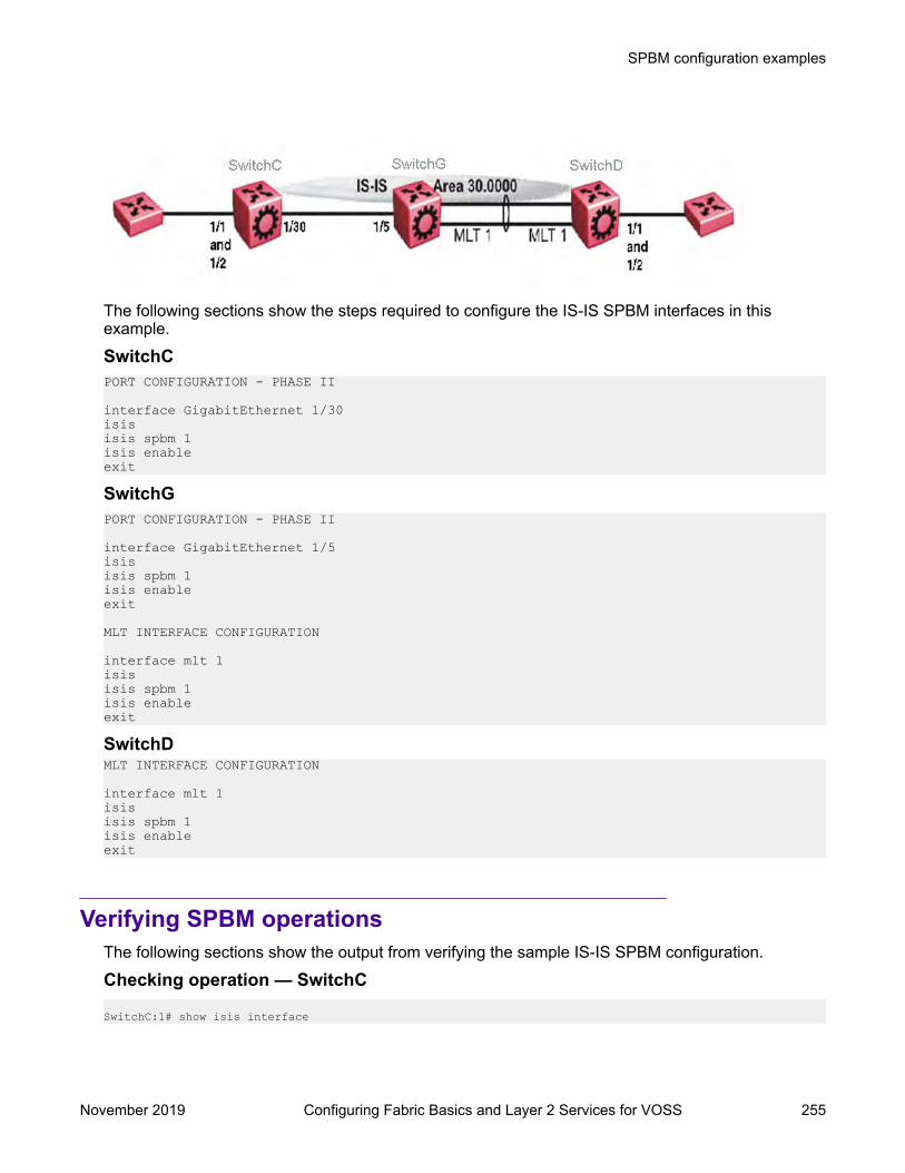
The following sections show the steps required to configure the IS-IS SPBM interfaces in thisexample.
SwitchCPORT CONFIGURATION - PHASE II
interface GigabitEthernet 1/30isis isis spbm 1 isis enable exit
SwitchGPORT CONFIGURATION - PHASE II
interface GigabitEthernet 1/5isis isis spbm 1 isis enable exit
MLT INTERFACE CONFIGURATION
interface mlt 1isisisis spbm 1isis enableexit
SwitchDMLT INTERFACE CONFIGURATION
interface mlt 1isisisis spbm 1isis enableexit
Verifying SPBM operationsThe following sections show the output from verifying the sample IS-IS SPBM configuration.
Checking operation — SwitchC
SwitchC:1# show isis interface
SPBM configuration examples
November 2019 Configuring Fabric Basics and Layer 2 Services for VOSS 255

================================================================================ ISIS Interfaces================================================================================IFIDX TYPE LEVEL OP-STATE ADM-STATE ADJ UP-ADJ SPBM-L1-METRIC--------------------------------------------------------------------------------Port1/30 pt-pt Level 1 UP UP 1 1 10
SwitchC:1# show isis adjacencies================================================================================================ ISIS Adjacencies================================================================================================INTERFACE L STATE UPTIME PRI HOLDTIME SYSID HOST-NAME STATUS ------------------------------------------------------------------------------------------------Port1/30 1 UP 1d 19:19:52 22 beb0.0000.7204 SwitchC ACTIVE
-------------------------------------------------------------------------------- 1 out of 1 interfaces have formed an adjacency--------------------------------------------------------------------------------
SwitchC:1# show isis spbm unicast-fib================================================================================ SPBM UNICAST FIB ENTRY INFO================================================================================DESTINATION BVLAN SYSID HOST-NAME OUTGOING-INTERFACE COSTADDRESS--------------------------------------------------------------------------------00:0e:62:25:a3:df 4000 000e.6225.a3df SwitchG 1/3000:14:0d:a0:13:df 4000 0014.0da0.13df SwitchD 1/30
-------------------------------------------------------------------------------- Total number of SPBM UNICAST FIB entries 2--------------------------------------------------------------------------------
SwitchC:1# show isis spbm unicast-tree 4000Node:000e.6225.a3df.00 (SwitchG) -> ROOTNode:0014.0da0.13df.00 (SwitchD) -> Node:000e.6225.a3df.00 (SwitchG) ->ROOT
Checking operation — SwitchGSwitchG:1# show isis interface================================================================================ ISIS Interfaces================================================================================IFIDX TYPE LEVEL OP-STATE ADM-STATE ADJ UP-ADJ SPBM-L1-METRIC--------------------------------------------------------------------------------Port1/5 pt-pt Level 1 UP UP 1 1 10Mlt1 pt-pt Level 1 UP UP 1 1 10
SwitchG:1# show isis adjacencies==================================================================================== ISIS Adjacencies====================================================================================INTERFACE L STATE UPTIME PRI HOLDTIME SYSID HOST-NAME STATUS------------------------------------------------------------------------------------Port1/5 1 UP 1d 19:19:52 127 26 beb0.0000.7204 SwitchC ACTIVEMlt1 1 UP 04:57:34 127 20 0014.0da0.13df SwitchD ACTIVE-------------------------------------------------------------------------------- 2 out of 2 interfaces have formed an adjacency--------------------------------------------------------------------------------
SwitchG:1# show isis spbm unicast-fib================================================================================ SPBM UNICAST FIB ENTRY INFO================================================================================DESTINATION ADDRESS BVLAN SYSID HOST-NAME OUTGOING-INTERFACE COST--------------------------------------------------------------------------------00:14:0d:a0:13:df 4000 0014.0da0.13df SwitchD MLT-100:15:e8:9f:e3:df 4000 0015.e89f.e3df SwitchC 1/5
SPBM and IS-IS infrastructure configuration
November 2019 Configuring Fabric Basics and Layer 2 Services for VOSS 256

SwitchG:1# show isis spbm unicast-tree 4000Node:0015.e89f.e3df.00 (SwitchC) -> ROOTNode:0014.0da0.13df.00 (SwitchD) -> ROOT
Checking operation — SwitchDSwitchD:1# show isis interface================================================================================ ISIS Interfaces================================================================================IFIDX TYPE LEVEL OP-STATE ADM-STATE ADJ UP-ADJ SPBM-L1-METRIC--------------------------------------------------------------------------------Mlt1 pt-pt Level 1 UP UP 1 1 10
SwitchD:1# show isis adjacencies================================================================================================ ISIS Adjacencies================================================================================================INTERFACE L STATE UPTIME PRI HOLDTIME SYSID HOST-NAME STATUS ------------------------------------------------------------------------------------------------Mlt1 1 UP 05:03:59 127 21 000e.6225.a3df SwitchG ACTIVE -------------------------------------------------------------------------------- 1 out of 1 interfaces have formed an adjacency--------------------------------------------------------------------------------SwitchD:1# show isis spbm unicast-fib================================================================================ SPBM UNICAST FIB ENTRY INFO================================================================================DESTINATION ADDRESS BVLAN SYSID HOST-NAME OUTGOING-INTERFACE COST--------------------------------------------------------------------------------00:0e:62:25:a3:df 4000 000e.6225.a3df SwitchG MLT-100:15:e8:9f:e3:df 4000 0015.e89f.e3df SwitchC MLT-1
SwitchD:1# show isis spbm unicast-tree 4000Node:000e.6225.a3df.00 (SwitchG) -> ROOTNode:0015.e89f.e3df.00 (SwitchC) -> Node:000e.6225.a3df.00 (SwitchG) ->ROOT
Fabric Extend configuration examplesThis section provides configuration examples to configure Fabric Extend in the following deploymentscenarios.
• Fabric Extend over IP using the GRT on page 257• Fabric Extend over IP using a VRF on page 261• Fabric Extend over VPLS on page 263• Fabric Extend over Pseudowires on page 266• Fabric Extend with ONAs in the core and branches on page 268• Fabric Extend over IPsec on page 271
For more configuration examples, see Shortest Path Bridging (802.1aq) Technical ConfigurationGuide.
Fabric Extend over IP using the GRTThis example shows a typical Fabric Extend deployment with a 10/40/100 Gbps switch in the coreand a 1 Gbps switch in one of the branch offices. The 10/40/100 Gbps switch supports Fabric
Fabric Extend configuration examples
November 2019 Configuring Fabric Basics and Layer 2 Services for VOSS 257

Extend natively and is connected over an IP network to a 1 Gbps switch, which requires an ONA toencapsulate SPB traffic with a VXLAN header. The ONA sets up a bridge between the ONA device-side port and the ONA network-side port. Fabric Extend uses a VXLAN tunnel to send traffic to andfrom the 10/40/100 Gbps switch through the 1 Gbps switch to the ONA.
Note:• This deployment uses the GRT so the tunnel source IP address must be on the GRT, not
on a VRF.
• If IP Shortcuts is enabled, you must configure an IS-IS accept policy or exclude route-mapto ensure that tunnel destination IP addresses are not learned through IS-IS.
• Add any IP address used for setting up the logical tunnel (such as local network andloopback IP addresses) to the IS-IS accept policy or exclude route-map to prevent theseaddresses from being advertised into IS-IS.
The following figure shows a sample Fabric Extend deployment over IP using the GRT.
Figure 28: IP using GRT traffic flow
Figure 29: IP (GRT) traffic flow component view
For 10/40/100 Gbps Switches(The tunnel source IP address is configured in the GRT.)Switch(config)# interface GigabitEthernet 2/14Switch(config-if)# no shutdownSwitch(config-if)# default-vlan-id 0Switch(config-if)# name "ospf-intf-SP-core"Switch(config-if)# brouter port 2/14 vlan 3036 subnet 197.1.1.2/255.255.255.0 Switch(config-if)# no spanning-tree mstp force-port-state enableSwitch(config-if)# ip ospf enableSwitch(config-if)# exit
SPBM and IS-IS infrastructure configuration
November 2019 Configuring Fabric Basics and Layer 2 Services for VOSS 258
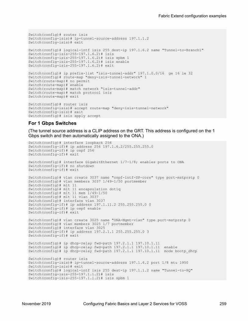
Switch(config)# router isisSwitch(config-isis)# ip-tunnel-source-address 197.1.1.2Switch(config-isis)# exit
Switch(config)# logical-intf isis 255 dest-ip 197.1.6.2 name "Tunnel-to-Branch1"Switch(config-isis-255-197.1.6.2)# isisSwitch(config-isis-255-197.1.6.2)# isis spbm 1Switch(config-isis-255-197.1.6.2)# isis enableSwitch(config-isis-255-197.1.6.2)# exit
Switch(config)# ip prefix-list "isis-tunnel-addr" 197.1.0.0/16 ge 16 le 32Switch(config)# route-map "deny-isis-tunnel-network" 1Switch(route-map)# no permitSwitch(route-map)# enableSwitch(route-map)# match network "isis-tunnel-addr"Switch(route-map)# match protocol isisSwitch(route-map)# exit
Switch(config)# router isisSwitch(config-isis)# accept route-map "deny-isis-tunnel-network"Switch(config-isis)# exitSwitch(config)# isis apply accept
For 1 Gbps Switches(The tunnel source address is a CLIP address on the GRT. This address is configured on the 1Gbps switch and then automatically assigned to the ONA.)Switch(config)# interface loopback 256Switch(config-if)# ip address 256 197.1.6.2/255.255.255.0Switch(config-if)# ip ospf 256Switch(config-if)# exit
Switch(config)# interface GigabitEthernet 1/7-1/8; enables ports to ONASwitch(config-if)# no shutdownSwitch(config-if)# exit
Switch(config)# vlan create 3037 name "ospf-intf-SP-core" type port-mstprstp 0Switch(config)# vlan members 3037 1/49-1/50 portmemberSwitch(config)# mlt 11Switch(config)# mlt 11 encapsulation dot1qSwitch(config)# mlt 11 mem 1/49-1/50Switch(config)# mlt 11 vlan 3037Switch(config)# interface vlan 3037Switch(config-if)# ip address 197.1.11.2 255.255.255.0 0Switch(config-if)# ip ospf enableSwitch(config-if)# exit
Switch(config)# vlan create 3025 name "ONA-Mgmt-vlan" type port-mstprstp 0Switch(config)# vlan members 3025 1/7 portmemberSwitch(config)# interface vlan 3025Switch(config-if)# ip address 197.2.1.1 255.255.255.0 3Switch(config-if)# exit
Switch(config)# ip dhcp-relay fwd-path 197.2.1.1 197.10.1.11Switch(config)# ip dhcp-relay fwd-path 197.2.1.1 197.10.1.11 enableSwitch(config)# ip dhcp-relay fwd-path 197.2.1.1 197.10.1.11 mode bootp_dhcp
Switch(config)# router isis Switch(config-isis)# ip-tunnel-source-address 197.1.6.2 port 1/8 mtu 1950Switch(config-isis)# exitSwitch(config)# logical-intf isis 255 dest-ip 197.1.1.2 name "Tunnel-to-HQ"Switch(config-isis-255-197.1.1.2)# isisSwitch(config-isis-255-197.1.1.2)# isis spbm 1
Fabric Extend configuration examples
November 2019 Configuring Fabric Basics and Layer 2 Services for VOSS 259

Switch(config-isis-255-197.1.1.2)# isis enableSwitch(config-isis-255-197.1.1.2)# exit
Switch(config)# ip prefix-list "isis-tunnel-addr" 197.1.0.0/16 ge 16 le 32Switch(config)# route-map "deny-isis-tunnel-network" 1Switch(route-map)# no permitSwitch(route-map)# enableSwitch(route-map)# match network "isis-tunnel-addr"Switch(route-map)# match protocol isisSwitch(route-map)# exit
Switch(config)# router isis Switch(config-isis)# accept route-map "deny-isis-tunnel-network"Switch(config-isis)# exitSwitch(config)# isis apply accept
Intermediate routers are typically configured by an Internet service provider (ISP). The followingconfigurations are for reference only.
For Intermediate Router 1Switch(config)# interface GigabitEthernet 8/19Switch(config-if)# default-vlan-id 0Switch(config-if)# name "ospf-intf-from-Headoffice"Switch(config-if)# no shutdownSwitch(config-if)# brouter port 8/19 vlan 3036 subnet 197.1.1.3/255.255.255.0 mac-offset 2Switch(config-if)# ip ospf enableSwitch(config-if)# exit
Switch(config)# vlan create 3039 name "core-ospf-vlan" type port-mstprstp 0Switch(config)# vlan members 3039 8/1 portmemberSwitch(config)# interface Vlan 3039Switch(config)# ip address 197.1.8.1 255.255.255.0 2 Switch(config)# ip ospf enableSwitch(config)# exit
For Intermediate Router 2Switch(config)# vlan create 3039 name "core-ospf-vlan" type port-mstprstp 0Switch(config)# vlan members 3039 8/1 portmemberSwitch(config)# interface Vlan 3039Switch(config)# ip address 197.1.8.2 255.255.255.0 0 Switch(config)# ip ospf enableSwitch(config)# exit
Switch(config)# vlan create 3037 name "ospf-intf-from-branch1" type port-mstprstp 0Switch(config)# vlan members 3037 8/21-8/22 portmemberSwitch(config)# mlt 11Switch(config)# mlt 11 encapsulation dot1qSwitch(config)# mlt 11 mem 8/21-8/22Switch(config)# mlt 11 vlan 3037Switch(config)# interface Vlan 3037Switch(config)# ip address 197.1.11.1 255.255.255.0 5 Switch(config)# ip ospf enableSwitch(config)# exit
SPBM and IS-IS infrastructure configuration
November 2019 Configuring Fabric Basics and Layer 2 Services for VOSS 260

Fabric Extend over IP using a VRFThis example is the same as the previous IP example except this Fabric Extend deployment uses aVRF instead of the GRT. Because this deployment is using a VRF, Fabric Extend has the followingrequirements:
• Configure a CLIP and tunnel source IP address on the same VRF.
• Remote management of the 1 Gbps switch is only possible after establishing IP Shortcut overIS-IS. (Alternatively, you can enable GRT-VRF redistribution locally.)
The following figure shows a sample Fabric Extend deployment over IP using a VRF.
Figure 30: IP using VRF traffic flow
Figure 31: IP (VRF) traffic flow component view
For 10/40/100 Gbps Switches(The tunnel source IP address is configured as a brouter address in the VRF.)Switch(config)# ip vrf vrf24Switch(config)# router vrf vrf24Switch(router-vrf)# ip ospfSwitch(router-vrf)# ip ospf admin-stateSwitch(router-vrf)# exit
Switch(config)# interface GigabitEthernet 2/14Switch(config-if)# no shutdownSwitch(config-if)# default-vlan-id 0Switch(config-if)# name "ospf-intf-SP-core"Switch(config-if)# vrf vrf24Switch(config-if)# brouter port 2/14 vlan 3036 subnet 197.1.1.2/255.255.255.0 mac-offset 1Switch(config-if)# no spanning-tree mstp force-port-state enable
Fabric Extend configuration examples
November 2019 Configuring Fabric Basics and Layer 2 Services for VOSS 261

Switch(config-if)# ip ospf enableSwitch(config-if)# exit
Switch(config)# router isisSwitch(config-isis)# ip-tunnel-source-address 197.1.1.2 vrf vrf24Switch(config-isis)# exit
Switch(config)# logical-intf isis 255 dest-ip 197.1.6.2 name "Tunnel-to-Branch1"Switch(config-isis-255-197.1.6.2)# isisSwitch(config-isis-255-197.1.6.2)# isis spbm 1Switch(config-isis-255-197.1.6.2)# isis enableSwitch(config-isis-255-197.1.6.2)# exit
For 1 Gbps Switches(The tunnel source address is a CLIP address on the VRF. This address is configured on the 1 Gbpsswitch and then automatically assigned to the ONA.)Switch(config)# ip vrf vrf24
Switch(config)# router vrf vrf24Switch(router-vrf)# ip ospfSwitch(router-vrf)# ip ospf admin-stateSwitch(router-vrf)# exit
Switch(config)# interface loopback 256Switch(config-if)# ip address 197.1.6.2 255.255.255.255 vrf vrf24Switch(config-if)# ip ospf vrf vrf24Switch(config-if)# exit
Switch(config)# interface GigabitEthernet 1/7-1/8; enables ports to ONASwitch(config-if)# no shutdownSwitch(config-if)# exit
Switch(config)# vlan create 3037 name "ospf-intf-SP-core" type port-mstprstp 0Switch(config)# vlan members 3037 1/49-1/50 portmemberSwitch(config)# mlt 11 Switch(config)# mlt 11 encapsulation dot1q Switch(config)# mlt 11 mem 1/49-1/50 Switch(config)# mlt 11 vlan 3037Switch(config)# interface vlan 3037Switch(config-if)# vrf vrf24Switch(config-if)# ip address 197.1.11.2 255.255.255.0 0Switch(config-if)# ip ospf enableSwitch(config-if)# exit
Switch(config)# vlan create 3025 name "ONA-Mgmt-vlan" type port-mstprstp 0Switch(config)# vlan members 3025 1/7 portmemberSwitch(config)# interface vlan 3025Switch(config-if)# ip address 197.2.1.1 255.255.255.0 3Switch(config-if)# exit
Switch(config)# ip dhcp-relay fwd-path 197.2.1.1 197.10.1.11Switch(config)# ip dhcp-relay fwd-path 197.2.1.1 197.10.1.11 enableSwitch(config)# ip dhcp-relay fwd-path 197.2.1.1 197.10.1.11 mode bootp_dhcp
Switch(config)# router isis Switch(config-isis)# ip-tunnel-source-address 197.1.6.2 port 1/8 vrf vrf24 mtu 1950Switch(config-isis)# exit
Switch(config)# logical-intf isis 255 dest-ip 197.1.1.2 name "Tunnel-to-HQ"Switch(config-isis-255-197.1.1.2)# isisSwitch(config-isis-255-197.1.1.2)# isis spbm 1Switch(config-isis-255-197.1.1.2)# isis enableSwitch(config-isis-255-197.1.1.2)# exit
SPBM and IS-IS infrastructure configuration
November 2019 Configuring Fabric Basics and Layer 2 Services for VOSS 262

Intermediate routers are typically configured by an Internet service provider (ISP). The followingconfigurations are for reference only.
For Intermediate Router 1Switch(config)# interface GigabitEthernet 8/19Switch(config-if)# default-vlan-id 0Switch(config-if)# name "ospf-intf-from-Headoffice"Switch(config-if)# no shutdownSwitch(config-if)# brouter port 8/19 vlan 3036 subnet 197.1.1.3/255.255.255.0 mac-offset 2Switch(config-if)# ip ospf enableSwitch(config-if)# exit
Switch(config)# vlan create 3039 name "core-ospf-vlan" type port-mstprstp 0Switch(config)# vlan members 3039 8/1 portmemberSwitch(config)# interface Vlan 3039Switch(config)# ip address 197.1.8.1 255.255.255.0 2 Switch(config)# ip ospf enableSwitch(config)# exit
For Intermediate Router 2Switch(config)# vlan create 3039 name "core-ospf-vlan" type port-mstprstp 0Switch(config)# vlan members 3039 8/1 portmemberSwitch(config)# interface Vlan 3039Switch(config)# ip address 197.1.8.2 255.255.255.0 0 Switch(config)# ip ospf enableSwitch(config)# exit
Switch(config)# vlan create 3037 name "ospf-intf-from-branch1" type port-mstprstp 0Switch(config)# vlan members 3037 8/21-8/22 portmemberSwitch(config)# mlt 11 Switch(config)# mlt 11 encapsulation dot1q Switch(config)# mlt 11 mem 8/21-8/22 Switch(config)# mlt 11 vlan 3037Switch(config)# interface Vlan 3037Switch(config)# ip address 197.1.11.1 255.255.255.0 5 Switch(config)# ip ospf enableSwitch(config)# exit
Fabric Extend over VPLSThis example shows a Fabric Extend deployment over MPLS Virtual Private LAN Service (VPLS). Inthis scenario, VPLS emulates a LAN with full mesh connectivity. The SPB nodes connect with point-to-point Ethernet links and also use MPLS for normal forwarding.
Note:
On the Core side, the 10/40/100 Gbps switches require a single next hop IP address as adefault gateway for all tunnels. To ensure the single next hop, VPLS uses a loopback IP addressand an additional VRF.
The following figure shows a sample Fabric Extend deployment over VPLS.
Fabric Extend configuration examples
November 2019 Configuring Fabric Basics and Layer 2 Services for VOSS 263

Figure 32: FE over VPLS traffic flow
For 10/40/100 Gbps Switches(The tunnel source IP address is configured as a brouter address in the VRF.)Switch(config)# interface GigabitEthernet 2/14Switch(config-if)# no shutdownSwitch(config-if)# default-vlan-id 0Switch(config-if)# name "ospf-intf-SP-core"Switch(config-if)# vrf vrf24Switch(config-if)# brouter port 2/14 vlan 3036 subnet 197.1.1.2/255.255.255.0 mac-offset 1Switch(config-if)# no spanning-tree mstp force-port-state enableSwitch(config-if)# ip ospf enableSwitch(config-if)# exit
Switch(config)# router isisSwitch(config-isis)# ip-tunnel-source-address 197.1.1.2 vrf vrf24Switch(config-isis)# exitSwitch(config)# logical-intf isis 255 dest-ip 197.1.6.2 name "Tunnel-to-Branch1"Switch(config-isis-255-197.1.6.2)# isisSwitch(config-isis-255-197.1.6.2)# isis spbm 1Switch(config-isis-255-197.1.6.2)# isis enableSwitch(config-isis-255-197.1.6.2)# exit
For 1 Gbps Switches(The tunnel source address is a CLIP address on the VRF. This address is configured on the 1 Gbpsswitch and then automatically assigned to the ONA.)Switch(config)# ip vrf vrf24
Switch(config)# router vrf vrf24Switch(router-vrf)# ip ospfSwitch(router-vrf)# ip ospf admin-stateSwitch(router-vrf)# exit
Switch(config)# interface loopback 256Switch(config-if)# ip address 197.1.6.2 255.255.255.255 vrf vrf24Switch(config-if)# ip ospf vrf vrf24
SPBM and IS-IS infrastructure configuration
November 2019 Configuring Fabric Basics and Layer 2 Services for VOSS 264
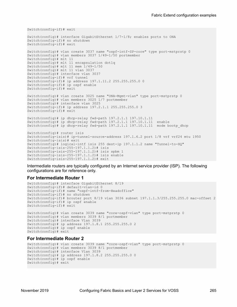
Switch(config-if)# exit
Switch(config)# interface GigabitEthernet 1/7-1/8; enables ports to ONASwitch(config-if)# no shutdownSwitch(config-if)# exit
Switch(config)# vlan create 3037 name "ospf-intf-SP-core" type port-mstprstp 0Switch(config)# vlan members 3037 1/49-1/50 portmemberSwitch(config)# mlt 11 Switch(config)# mlt 11 encapsulation dot1q Switch(config)# mlt 11 mem 1/49-1/50 Switch(config)# mlt 11 vlan 3037Switch(config)# interface vlan 3037Switch(config-if)# vrf tunnelSwitch(config-if)# ip address 197.1.11.2 255.255.255.0 0Switch(config-if)# ip ospf enableSwitch(config-if)# exit
Switch(config)# vlan create 3025 name "ONA-Mgmt-vlan" type port-mstprstp 0Switch(config)# vlan members 3025 1/7 portmemberSwitch(config)# interface vlan 3025Switch(config-if)# ip address 197.2.1.1 255.255.255.0 3Switch(config-if)# exit
Switch(config)# ip dhcp-relay fwd-path 197.2.1.1 197.10.1.11Switch(config)# ip dhcp-relay fwd-path 197.2.1.1 197.10.1.11 enableSwitch(config)# ip dhcp-relay fwd-path 197.2.1.1 197.10.1.11 mode bootp_dhcp
Switch(config)# router isis Switch(config-isis)# ip-tunnel-source-address 197.1.6.2 port 1/8 vrf vrf24 mtu 1950Switch(config-isis)# exitSwitch(config)# logical-intf isis 255 dest-ip 197.1.1.2 name "Tunnel-to-HQ"Switch(config-isis-255-197.1.1.2)# isisSwitch(config-isis-255-197.1.1.2)# isis spbm 1Switch(config-isis-255-197.1.1.2)# isis enableSwitch(config-isis-255-197.1.1.2)# exit
Intermediate routers are typically configured by an Internet service provider (ISP). The followingconfigurations are for reference only.
For Intermediate Router 1Switch(config)# interface GigabitEthernet 8/19Switch(config-if)# default-vlan-id 0Switch(config-if)# name "ospf-intf-from-Headoffice"Switch(config-if)# no shutdownSwitch(config-if)# brouter port 8/19 vlan 3036 subnet 197.1.1.3/255.255.255.0 mac-offset 2Switch(config-if)# ip ospf enableSwitch(config-if)# exit
Switch(config)# vlan create 3039 name "core-ospf-vlan" type port-mstprstp 0Switch(config)# vlan members 3039 8/1 portmemberSwitch(config)# interface Vlan 3039Switch(config)# ip address 197.1.8.1 255.255.255.0 2 Switch(config)# ip ospf enableSwitch(config)# exit
For Intermediate Router 2Switch(config)# vlan create 3039 name "core-ospf-vlan" type port-mstprstp 0Switch(config)# vlan members 3039 8/1 portmemberSwitch(config)# interface Vlan 3039Switch(config)# ip address 197.1.8.2 255.255.255.0 0 Switch(config)# ip ospf enableSwitch(config)# exit
Fabric Extend configuration examples
November 2019 Configuring Fabric Basics and Layer 2 Services for VOSS 265

Switch(config)# vlan create 3037 name "ospf-intf-from-branch1" type port-mstprstp 0Switch(config)# vlan members 3037 8/21-8/22 portmemberSwitch(config)# mlt 11 Switch(config)# mlt 11 encapsulation dot1q Switch(config)# mlt 11 mem 8/21-8/22 Switch(config)# mlt 11 vlan 3037Switch(config)# interface Vlan 3037Switch(config)# ip address 197.1.11.1 255.255.255.0 5 Switch(config)# ip ospf enableSwitch(config)# exit
Fabric Extend over Layer 2 PseudowireThis example shows a Fabric Extend deployment using service provider VLAN tunnels over MPLSPseudowire. In this scenario, you map two dedicated VLAN IDs (VIDs) from the Hub to the Spokesites. Then the logical IS-IS interfaces translate the BVIDs to map them to the per branch providerVIDs. Because the tunnels are point-to-point VLAN connections, not VXLAN, there is no need toencapsulate a VXLAN header to SPB packets. Therefore, the 1 Gbps switches in this type ofdeployment do not require ONAs.
Important:
10/40/100 Gbps switch — — — — — — Core — — — — — — 1 Gbps switch
• You cannot have IS-IS in the Core.
• Do not create the two VLANs represented in the logical interface connection on the BEBs.If you do, you will not be able add any Fabric Extend ports to be members of those VLANs.One links the port that is facing the core and those VLANs in the logical interfaceconnection.
The following figure shows a sample Fabric Extend deployment over Pseudowire.
Figure 33: FE over Pseudowire traffic flow
SPBM and IS-IS infrastructure configuration
November 2019 Configuring Fabric Basics and Layer 2 Services for VOSS 266

Figure 34: FE over Pseudowire traffic flow component view
For 10/40/100 Gbps SwitchesNote:Logical interface VLANs cannot be the same as the SPBM B-VLANs and you cannot createthese VLANs locally. Use these VLANs for configuring the logical interface only. Once a port isbeing used for a logical interface it cannot be added to any platform VLAN and spanning tree isautomatically disabled on the port.
Switch(config)# logical-intf isis 255 vid 200,300 primary-vid 200 port 2/14 name fe_to_SwitchSwitch(config-isis-255)# isisSwitch(config-isis-255)# isis spbm 1Switch(config-isis-255)# isis enableSwitch(config-isis-255)# exit
For 1 Gbps SwitchesNote:Logical interface VLANs cannot be the same as the SPBM B-VLANs and you cannot createthese VLANs locally. Use these VLANs for configuring the logical interface only. Once a port isbeing used for a logical interface it cannot be added to any platform VLAN and spanning tree isautomatically disabled on the port.
Switch(config)# mlt 11 Switch(config)# mlt 11 encapsulation dot1q Switch(config)# mlt 11 mem 1/49-1/50 Switch(config)# router isis enable
Switch(config)# logical-intf isis 255 vid 200,300 primary-vid 200 mlt 11 name fe_to_SwitchSwitch(config-isis-255)# isisSwitch(config-isis-255)# isis spbm 1Switch(config-isis-255)# isis enableSwitch(config-isis-255)# exit
Intermediate routers are typically configured by an Internet service provider (ISP). The followingconfigurations are for reference only.
For Intermediate Router 1Switch(config)# vlan create 200 type port-mstprstp 1Switch(config)# vlan create 300 type port-mstprstp 1Switch(config)# vlan member add 200 8/1,8/19Switch(config)# vlan member add 300 8/1,8/19
For Intermediate Router 2Switch(config)# mlt 11 Switch(config)# mlt 11 encapsulation dot1q Switch(config)# mlt 11 mem 8/21-8/22 Switch(config)# vlan create 200 type port-mstprstp 1Switch(config)# vlan create 300 type port-mstprstp 1
Fabric Extend configuration examples
November 2019 Configuring Fabric Basics and Layer 2 Services for VOSS 267

Switch(config)# vlan member add 200 8/1Switch(config)# vlan mlt 200 11Switch(config)# vlan member add 300 8/1Switch(config)# vlan mlt 300 11
Fabric Extend with ONAs in the core and branchesThis example shows a Fabric Extend deployment with 1 Gbps switches in the core of the networkand in the branch sites. This type of deployment is not only a lower cost Fabric Extend solution, italso addresses situations where large MTU sizes (over 1594 bytes) are a problem for the ServiceProvider.
MTU sizes less than 1594 bytes require fragmentation and reassembly of packets and the 1 Gbpsswitch with ONA supports fragmentation and reassembly. However, you must have 1 Gbps switcheswith ONAs at BOTH ends of the IP WAN connection.
Important:
There is no fragmentation/reassembly support in Layer 2 core solutions.
The following figure shows a sample Fabric Extend deployment using VRFs with both switches.
Figure 35: Fabric Extend traffic flow
Figure 36: Fabric Extend traffic flow component viewCore switch configuration(The tunnel source address is a CLIP address on the VRF. This address is configured on the switchand then automatically assigned to the ONA.)Switch(config)# ip vrf vrf24Switch(config)# router vrf vrf24
SPBM and IS-IS infrastructure configuration
November 2019 Configuring Fabric Basics and Layer 2 Services for VOSS 268

Switch(router-vrf)# ip ospfSwitch(router-vrf)# ip ospf admin-stateSwitch(router-vrf)# exit
Switch(config)# interface loopback 256Switch(config-if)# ip address 197.1.5.2 255.255.255.255 vrf vrf24Switch(config-if)# ip ospf vrf vrf24Switch(config-if)# exit
Switch(config)# interface GigabitEthernet 1/7-1/8; enables ports to ONASwitch(config-if)# no shutdownSwitch(config-if)# exit
Switch(config)# vlan create 3036 name "ospf-intf-SP-core" type port-mstprstp 0Switch(config)# vlan members 3036 1/14 portmemberSwitch(config)# interface vlan 3036Switch(config)# vrf vrf24Switch(config-if)# ip address 197.1.1.2 255.255.255.0 0Switch(config-if)# ip ospf enableSwitch(config-if)# exit
Switch(config)# vlan create 3024 name "ONA-Mgmt-vlan" type port-mstprstp 0Switch(config)# vlan members 3024 1/8 portmemberSwitch(config)# interface vlan 3024Switch(config-if)# ip address 197.3.1.1 255.255.255.0 3Switch(config-if)# exit
Switch(config)# ip dhcp-relay fwd-path 197.3.1.1 197.10.1.11Switch(config)# ip dhcp-relay fwd-path 197.3.1.1 197.10.1.11 enableSwitch(config)# ip dhcp-relay fwd-path 197.3.1.1 197.10.1.11 mode bootp_dhcp
Switch(config)# router isis Switch(config-isis)# ip-tunnel-source-address 197.1.5.2 port 1/7 vrf vrf24 mtu 1950Switch(config-isis)# exitSwitch(config)# logical-intf isis 255 dest-ip 197.1.6.2 name "Tunnel-to-Branch1"Switch(config-isis-255-197.1.6.2)# isisSwitch(config-isis-255-197.1.6.2)# isis spbm 1Switch(config-isis-255-197.1.6.2)# isis enableSwitch(config-isis-255-197.2.1.1)# exit
Branch switch configuration(The tunnel source address is a CLIP address on the VRF. This address is configured on the switchand then automatically assigned to the ONA.)Switch(config)# ip vrf vrf24
Switch(config)# router vrf vrf24Switch(router-vrf)# ip ospfSwitch(router-vrf)# ip ospf admin-stateSwitch(router-vrf)# exit
Switch(config)# interface loopback 256Switch(config-if)# ip address 197.1.6.2 255.255.255.255 vrf vrf24Switch(config-if)# ip ospf vrf vrf24Switch(config-if)# exit
Switch(config)# interface GigabitEthernet 1/7-1/8; enables ports to ONASwitch(config-if)# no shutdownSwitch(config-if)# exit
Switch(config)# vlan create 3037 name "ospf-intf-SP-core" type port-mstprstp 0Switch(config)# vlan members 3037 1/49-1/50 portmemberSwitch(config)# interface vlan 3037Switch(config-if)# vrf vrf24
Fabric Extend configuration examples
November 2019 Configuring Fabric Basics and Layer 2 Services for VOSS 269
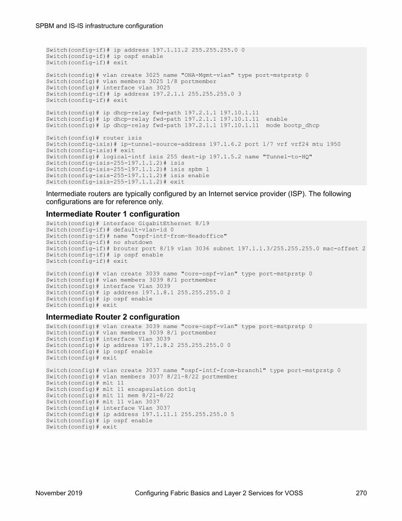
Switch(config-if)# ip address 197.1.11.2 255.255.255.0 0Switch(config-if)# ip ospf enableSwitch(config-if)# exit
Switch(config)# vlan create 3025 name "ONA-Mgmt-vlan" type port-mstprstp 0Switch(config)# vlan members 3025 1/8 portmemberSwitch(config)# interface vlan 3025Switch(config-if)# ip address 197.2.1.1 255.255.255.0 3Switch(config-if)# exit
Switch(config)# ip dhcp-relay fwd-path 197.2.1.1 197.10.1.11Switch(config)# ip dhcp-relay fwd-path 197.2.1.1 197.10.1.11 enableSwitch(config)# ip dhcp-relay fwd-path 197.2.1.1 197.10.1.11 mode bootp_dhcp
Switch(config)# router isis Switch(config-isis)# ip-tunnel-source-address 197.1.6.2 port 1/7 vrf vrf24 mtu 1950Switch(config-isis)# exitSwitch(config)# logical-intf isis 255 dest-ip 197.1.5.2 name "Tunnel-to-HQ"Switch(config-isis-255-197.1.1.2)# isisSwitch(config-isis-255-197.1.1.2)# isis spbm 1Switch(config-isis-255-197.1.1.2)# isis enableSwitch(config-isis-255-197.1.1.2)# exit
Intermediate routers are typically configured by an Internet service provider (ISP). The followingconfigurations are for reference only.
Intermediate Router 1 configurationSwitch(config)# interface GigabitEthernet 8/19Switch(config-if)# default-vlan-id 0Switch(config-if)# name "ospf-intf-from-Headoffice"Switch(config-if)# no shutdownSwitch(config-if)# brouter port 8/19 vlan 3036 subnet 197.1.1.3/255.255.255.0 mac-offset 2Switch(config-if)# ip ospf enableSwitch(config-if)# exit
Switch(config)# vlan create 3039 name "core-ospf-vlan" type port-mstprstp 0Switch(config)# vlan members 3039 8/1 portmemberSwitch(config)# interface Vlan 3039Switch(config)# ip address 197.1.8.1 255.255.255.0 2 Switch(config)# ip ospf enableSwitch(config)# exit
Intermediate Router 2 configurationSwitch(config)# vlan create 3039 name "core-ospf-vlan" type port-mstprstp 0Switch(config)# vlan members 3039 8/1 portmemberSwitch(config)# interface Vlan 3039Switch(config)# ip address 197.1.8.2 255.255.255.0 0 Switch(config)# ip ospf enableSwitch(config)# exit
Switch(config)# vlan create 3037 name "ospf-intf-from-branch1" type port-mstprstp 0Switch(config)# vlan members 3037 8/21-8/22 portmemberSwitch(config)# mlt 11 Switch(config)# mlt 11 encapsulation dot1q Switch(config)# mlt 11 mem 8/21-8/22 Switch(config)# mlt 11 vlan 3037Switch(config)# interface Vlan 3037Switch(config)# ip address 197.1.11.1 255.255.255.0 5 Switch(config)# ip ospf enableSwitch(config)# exit
SPBM and IS-IS infrastructure configuration
November 2019 Configuring Fabric Basics and Layer 2 Services for VOSS 270

Fabric Extend Over IPsecThe following example shows a Fabric Extend deployment using service provider VLAN tunnels andIPsec.
Note:Fabric Extend over IPsec limitations:
• Only pre-shared authentication key IPsec parameters are user configurable. Other, third-party solutions are not configurable.
• IPsec over NAT-T on a Fabric Extend tunnel is not supported.• The key exchange only uses the IKEv2 protocol.• IPsec support is only added for Fabric Extend tunnels.• IPsec is not supported for regular layer 3 routed packets.
Global SPBM for Fabric Extend over IPsec ConfigurationThe global SPBM parameters must be configured before you can configure the Fabric Extend overIPsec tunnel.
Note:The ipsec command is only available after the auth-key command is configured.
Switch> enableSwitch# configure terminal
Switch(config)# spbmSwitch(config-isis)# router isisSwitch(config-isis)# spbm 1Switch(config-isis)# spbm 1 nick-name 1.11.40 Switch(config-isis)# spbm 1 b-vid 2,3 primary 2Switch(config-isis)# is-type l1Switch(config-isis)# manual-area c0.2000.0000.00 Switch(config-isis)# sys-name SwitchB Switch(config-isis)# exit
Switch(config)# vlan create 2 type spbm-bvlanSwitch(config)# vlan create 3 type spbm-bvlanSwitch(config)# router isis enable
Fabric Extend tunnel and IPsec configurationConfiguring Fabric Extend over IPsec consists of two primary tasks: configuring the tunnel sourceaddress and configuring the logical interface. These tasks must be completed on both ends of thetunnel.
Switch> enableSwitch# configure terminal
Switch(config)# interface GigabitEthernet 1/1Switch(config-if)# brouter port 1/1 vlan 2500 subnet 192.0.2.0/255.255.255.0 mac-offset 0 Switch(config-if)# exit
Fabric Extend configuration examples
November 2019 Configuring Fabric Basics and Layer 2 Services for VOSS 271

Switch(config)# router isisSwitch(config-isis)# ip-tunnel-source-address 192.0.2.0Switch(config-isis)# exit
Switch(config)# logical-intf isis 1 dest-ip 198.51.100.0Switch(config-isis-1-198.51.100.0)# isisSwitch(config-isis-1-198.51.100.0)# isis spbm 1Switch(config-isis-1-198.51.100.0)# isis enableSwitch(config-isis-1-198.51.100.0)# auth-key 12345678Switch(config-isis-1-198.51.100.0)# ipsecSwitch(config-isis-1-198.51.100.0)# exit
Fabric Attach configuration examplesThis section provides configuration examples to configure Fabric Attach.
Configuring a Fabric Attach solutionThe following section describes a simple configuration example to configure Fabric Attach (FA) atthe edge of a Fabric Connect network. This is a typical deployment at its simplest level and ispowerful because of its use in conjunction with a Fabric Connect core.
About this taskConfiguring FA primarily consists of configuring the FA Server. The FA Server in turn discoversneighboring FA component devices (like the FA Proxies and FA Clients) using FA TLVs within theLLDP PDUs.In the following deployment, the switch at the edge of the Fabric Connect cloud is configured as theFA Server. On this switch, FA is enabled globally and at the interface (port) level. Another switch,functioning as the FA Proxy connects to the FA enabled port (1/3) on the FA Server. User A is anend user device that needs to send and receive data traffic from User B (another end user device)across the network.
SPBM and IS-IS infrastructure configuration
November 2019 Configuring Fabric Basics and Layer 2 Services for VOSS 272

Before you beginConfigure SPBM and IS-IS on the edge and core switches. For more information, see Configuringminimum SPBM and IS-IS parameters on page 98.
ProcedureConfigure the edge switch (BEB) as the FA Server:1. Enter Global Configuration mode:
enableconfigure terminal
2. Enable FA globally:
fa enable3. Enter port interface configuration mode:
interface GigabitEthernet {slot/port[/sub-port] [-slot/port[/sub-port]] [,...]}
4. Enable FA on the port:
fa enable
Note:
Enabling FA automatically enables message authentication. Also, the authentication keyis set to the default value and appears encrypted on the output.
Note:
Enabling FA on a port not only enables tagging but also disables spanning tree on thatport.
Verify global and interface level FA configuration:
Fabric Attach configuration examples
November 2019 Configuring Fabric Basics and Layer 2 Services for VOSS 273
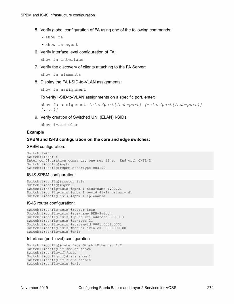
5. Verify global configuration of FA using one of the following commands:
• show fa• show fa agent
6. Verify interface level configuration of FA:
show fa interface7. Verify the discovery of clients attaching to the FA Server:
show fa elements8. Display the FA I-SID-to-VLAN assignments:
show fa assignmentTo verify I-SID-to-VLAN assignments on a specific port, enter:
show fa assignment {slot/port[/sub-port] [-slot/port[/sub-port]][,...]}
9. Verify creation of Switched UNI (ELAN) I-SIDs:
show i-sid elanExampleSPBM and IS-IS configuration on the core and edge switches:SPBM configuration:Switch:1>enSwitch:1#conf tEnter configuration commands, one per line. End with CNTL/Z.Switch:1(config)#spbmSwitch:1(config)#spbm ethertype 0x8100
IS-IS SPBM configuration:Switch:1(config)#router isisSwitch:1(config)#spbm 1Switch:1(config-isis)#spbm 1 nick-name 1.00.01Switch:1(config-isis)#spbm 1 b-vid 41-42 primary 41Switch:1(config-isis)#spbm 1 ip enable
IS-IS router configuration:Switch:1(config-isis)#router isisSwitch:1(config-isis)#sys-name BEB-SwitchSwitch:1(config-isis)#ip-source-address 3.3.3.3Switch:1(config-isis)#is-type l1Switch:1(config-isis)#system-id 0001.0001.0001Switch:1(config-isis)#manual-area c0.2000.000.00Switch:1(config-isis)#exit
Interface (port-level) configurationSwitch:1(config)#interface GigabitEthernet 1/2Switch:1(config-if)#no shutdownSwitch:1(config-if)#isisSwitch:1(config-if)#isis spbm 1Switch:1(config-if)#isis enableSwitch:1(config-isis)#exit
SPBM and IS-IS infrastructure configuration
November 2019 Configuring Fabric Basics and Layer 2 Services for VOSS 274

Switch(config)#vlan create 41 type spbm-vlanSwitch(config)#vlan create 42 type spbm-vlanSwitch(config)#router isis enableSwitch(config)#show isis spbm
Configuration of the edge switch as the FA Server.Enable FA globally.Switch:1(config)#fa enable Switch:1(config)#show fa
========================================================= Fabric Attach Configuration========================================================= FA Service : enabled FA Element Type : server FA Assignment Timeout : 240 FA Discovery Timeout : 240 FA Provision Mode : spbm
Enable FA on the port.Enabling FA automatically enables message authentication. The authentication key is configuredwith the default value, which appears in encrypted format in the output.Switch:1(config)#int gigabitEthernet 1/3Switch:1(config-if)#fa enableSwitch:1(config-if)#show fa interface port 1/3
============================================================= Fabric Attach Interfaces=============================================================INTERFACE SERVER MGMT MGMT MSG AUTH MSG AUTH STATUS ISID CVID STATUS KEY -------------------------------------------------------------Port1/3 enabled 0 0 enabled ****
------------------------------------------------------------- 1 out of 1 Total Num of fabric attach interfaces displayed-------------------------------------------------------------Switch:1(config-if)#exitSwitch:1(config)#exit
Verify that the FA Proxy is discovered by the FA Server.Switch:1(config)#show fa elements
================================================================================ Fabric Attach Discovery Elements================================================================================ MGMT ELEM ASGNPORT TYPE VLAN STATE SYSTEM ID AUTH AUTH--------------------------------------------------------------------------------1/3 proxy 2 T / S 10:cd:ae:09:40:00:20:00:00:01 AP AP
================================================================================ Fabric Attach Authentication Detail================================================================================ ELEM OPER ASGN OPERPORT AUTH STATUS AUTH STATUS--------------------------------------------------------------------------------1/3 successAuth successAuth
Fabric Attach configuration examples
November 2019 Configuring Fabric Basics and Layer 2 Services for VOSS 275

State Legend: (Tagging/AutoConfig)T= Tagged, U= Untagged, D= Disabled, S= Spbm, V= Vlan, I= Invalid
Auth Legend:AP= Authentication Pass, AF= Authentication Fail,NA= Not Authenticated, N= None
--------------------------------------------------------------------------------
2 out of 2 Total Num of fabric attach discovery elements displayed
Verify the FA I-SID-to-VLAN assignment. An active state indicates that the FA (ELAN) I-SID issuccessfully created with endpoint of type Switched UNI. By default, this I-SID is created for Layer2.Switch:1#show fa assignment
======================================================================== Fabric Attach Assignment Map========================================================================Interface I-SID Vlan State Origin------------------------------------------------------------------------1/3 44 2 active proxy
------------------------------------------------------------------------ 1 out of 1 Total Num of fabric attach assignment mappings displayed------------------------------------------------------------------------
For Layer 3 support, you must configure a platform VLAN. The platform VLAN can have the samevalue as that of the C-VID or it can have a different value.In this example, the platform VLAN has the same value as the C-VID.Switch:1(config)#vlan create 2 type port-mstprstp 0Switch:1(config)#vlan i-sid 2 44Switch:1#show i-sid elan
====================================================================== Isid Info======================================================================ISID ISID PORT MLT ORIGINID TYPE VLANID INTERFACES INTERFACES----------------------------------------------------------------------44 ELAN 2 c2:1/3 DISC_LOCAL
c: customer vid u: untagged-traffic
All 1 out of 1 Total Num of Elan i-sids displayed
Verify neighbor discovery on the FA Proxy switch:Note that the edge switch (BEB) is discovered as the FA Server by the FA Proxy.Switch:2(config)#show fa agent
Fabric Attach Service Status: EnabledFabric Attach Element Type: ProxyFabric Attach Zero Touch Status: EnabledFabric Attach Auto Provision Setting: ProxyFabric Attach Provision Mode: SPBMFabric Attach Client Proxy Status: Enabled
SPBM and IS-IS infrastructure configuration
November 2019 Configuring Fabric Basics and Layer 2 Services for VOSS 276

Fabric Attach Standalone Proxy Status: DisabledFabric Attach Agent Timeout: 50 secondsFabric Attach Extended Logging Status: EnabledFabric Attach Primary Server Id: aa:bb:cc:dd:ee:11:30:01:00:01 (SPBM)Fabric Attach Primary Server Descr:BEB-Switch (6.0.0.0_GA)Switch:2(config)#show fa elements
Unit/ Element Element Element Port Type Subtype VLAN Auth System ID ------- ------- -------------------- ------- ---- -----------------------------1/3 Server Server (Auth) 0 AP aa:bb:cc:dd:ee:11:30:01:00:01Switch:2(config)#show fa i-sid
I-SID VLAN Source Status ------- ---- ------------ ------- 44 2 Proxy Active
Configuring Fabric Attach in an SMLTThe following example describes FA configuration and behavior in a dual-homed SMLT deployment.
The following figure shows a simple FA solution in a dual-homed SMLT deployment. In thisdeployment, a pair of BEB switches (BEB A and BEB B) operating as IST peers are configured asthe FA Server. An access switch or a wiring closet switch configured as an FA Proxy connects to theFA Server. The FA Proxy advertises I-SID-to-VLAN assignment mappings to the FA Server. BothBEB switches receive the mapping information using LLDP PDUs containing assignment TLVs. Theswitch that learns the mapping first considers the I-SID to be discovered locally and creates the I-SID on its device. The mapping information is then shared with its IST peer switch. When the peerswitch receives the mapping across IST in a new SMLT message, it too creates the I-SID on itsdevice. This I-SID however, is considered to be discovered remotely because it is learnt fromsynchronization with the peer switch. The mappings can also be learned on the FA Server from bothLLDP PDUs and from IST synchronization.
Fabric Attach configuration examples
November 2019 Configuring Fabric Basics and Layer 2 Services for VOSS 277

Figure 37: FA configuration in dual-homed SMLT
Before you beginEnsure that the proxy device (for example, an access switch) is properly configured for FA. See thecorresponding product documentation for information on how to configure FA on the switch.
Procedure1. Configure SMLT and vIST on switches BEB A and BEB B.
Caution:
For the IST peer switches acting as the FA Server to transmit the same FA System ID(based on the virtual MAC), SMLT configuration on both the switches must be the same.
For detailed information on configuring SMLT and vIST, see Configuring Link Aggregation,MLT, SMLT and vIST for VOSS.
Configure BEB A and BEB B as the FA Server
Perform the following configuration on each switch.
2. Enter Global Configuration mode:
enable
SPBM and IS-IS infrastructure configuration
November 2019 Configuring Fabric Basics and Layer 2 Services for VOSS 278

configure terminal3. Enable FA globally:
fa enable4. Enter MLT interface configuration mode:
interface mlt <1–512>5. Enable FA on the MLT:
fa enable
Note:
Enabling FA automatically enables message authentication. Also, the authentication keyis set to the default value and appears encrypted on the output.
6. (Optional) Configure an FA authentication key with a value different from that of the defaultvalue:
fa authentication-key [WORD<0-32>]
Caution:
When you configure the FA authentication key, you must configure the same value onboth BEB switches in the SMLT.
Verify global and MLT-level FA configuration on BEB A and BEB B:7. Verify global configuration of FA using one of the following commands:
• show fa• show fa agent
8. Verify MLT-level (interface-level) configuration of FA:
show fa interfaceVerify FA discovery on BEB A and BEB B:9. Verify discovery of the FA Proxy.
show fa elementsView FA I-SID-to-VLAN assignments on BEB A and BEB B:10. View the FA I-SID-to-VLAN assignments:
show fa assignmentTo view FA I-SID-to-VLAN assignments on specific ports, enter:
show fa assignment {slot/port[/sub-port] [-slot/port[/sub-port]][,...]}
Verify creation of Switched UNI I-SIDs on BEB A and BEB B:
Fabric Attach configuration examples
November 2019 Configuring Fabric Basics and Layer 2 Services for VOSS 279

11. Verify creation of Switched UNI (ELAN) I-SIDs. Use the following commands:
• View ELAN I-SID information using show i-sid elan.
• View ELAN I-SID information on a specific MLT using show mlt i-sid [<1–512>].
Note:
Viewing ELAN I-SID information on an MLT is very useful to understand the origin ofthe I-SID, when multiple client or proxy devices connecting to the FA Server usingSMLT MLT advertise the same I-SID-to-VLAN mappings. In the event of a link failureon an MLT, the origin of the I-SID helps determine on which MLT, and thereby fromwhich proxy or client device, the mappings were successfully learnt.
ExampleSMLT configuration on BEB A and BEB B:On BEB A:Switch:1>enSwitch:1#conf tEnter configuration commands, one per line. End with CNTL/Z.Switch:1(config)#interface mlt 1Switch:1(config)#smlt
On BEB B:Switch:2>enSwitch:2#conf tEnter configuration commands, one per line. End with CNTL/Z.Switch:2(config)#interface mlt 1Switch:2(config)#smlt
vIST configuration on BEB A and BEB B:On BEB A:Switch:1(config)#vlan create 2261 type port-mstprstp 0Switch:1(config)#vlan i-sid 2261 1502261Switch:1(config)#interface vlan 2261Switch:1(config)#ip address 192.0.2.0 255.255.255.0 2
Configure BEB B (IP address 192.0.2.1) as the IST peer.Switch:1(config)#virtual-ist peer-ip 192.0.2.1 vlan 2261Switch:1(config)#show virtual-istSwitch:1(config)#exit
On BEB B:Switch:2(config)#vlan create 2261 type port-mstprstp 0Switch:2(config)#vlan i-sid 2261 1502261Switch:2(config)#interface vlan 2261Switch:2(config)#ip address 192.0.2.1 255.255.255.0 2
Configure BEB A (IP address 192.0.2.1) as the IST peer.Switch:2(config)#virtual-ist peer-ip 192.0.2.1 vlan 2261Switch:2(config)#show virtual-istSwitch:2(config)#exit
FA configuration on BEB A:
SPBM and IS-IS infrastructure configuration
November 2019 Configuring Fabric Basics and Layer 2 Services for VOSS 280

Enable FA globally and on the MLT:Switch:1(config)#fa enableSwitch:1(config)#show fa======================================================================== Fabric Attach Configuration======================================================================== FA Service : enabled FA Element Type : server FA Assignment Timeout : 240 FA Discovery Timeout : 240 FA Provision Mode : spbm
Optionally, configure an FA authentication key with the value dual-homed-smlt. Ensure that youconfigure the same value on both switches BEB A and BEB B.Switch:1(config)#interface mlt 1Switch:1(config-mlt)#fa authentication-key dual-homed-smlt
Enable FA on the MLT:Switch:1(config-mlt)#fa enableSwitch:1(config-mlt)#exitSwitch:1(config)#show fa interface
==================================================================== Fabric Attach Interfaces====================================================================INTERFACE SERVER MGMT MGMT MSG AUTH MSG AUTH STATUS ISID CVID STATUS KEY --------------------------------------------------------------------Mlt1 enabled 0 0 enabled ****
-------------------------------------------------------------------- 1 out of 1 Total Num of fabric attach interfaces displayed--------------------------------------------------------------------
Verify discovery of the FA Proxy:Switch:1(config)#show fa elements
================================================================================ Fabric Attach Discovery Elements================================================================================ MGMT ELEM ASGNPORT TYPE VLAN STATE SYSTEM ID AUTH AUTH--------------------------------------------------------------------------------3/21 proxy 2 T / S 10:cd:ae:09:40:00:20:00:00:01 AP AP3/22 proxy 2 T / S 10:cd:ae:09:40:00:20:00:00:01 AP AP3/23 proxy 2 T / S 10:cd:ae:09:40:00:20:00:00:01 AP AP
================================================================================ Fabric Attach Authentication Detail================================================================================ ELEM OPER ASGN OPERPORT AUTH STATUS AUTH STATUS--------------------------------------------------------------------------------3/21 successAuth successAuth3/22 successAuth successAuth3/23 successAuth successAuth
State Legend: (Tagging/AutoConfig)T= Tagged, U= Untagged, D= Disabled, S= Spbm, V= Vlan, I= Invalid
Auth Legend:
Fabric Attach configuration examples
November 2019 Configuring Fabric Basics and Layer 2 Services for VOSS 281

AP= Authentication Pass, AF= Authentication Fail,NA= Not Authenticated, N= None
--------------------------------------------------------------------------------
3 out of 3 Total Num of fabric attach discovery elements displayed
The FA Proxy advertises I-SID-to-VLAN assignment mappings to BEB A, on MLT ports 3/21 to3/23. View the FA I-SID-to-VLAN assignments on BEB-A:
All ports in the MLT receive the FA assignment mappings, as shown in the following output.Switch:1(config)#show fa assignment =================================================== Fabric Attach Assignment Map ==================================================Interface I-SID Vlan State Origin---------------------------------------------------3/21 2 2 active proxy3/21 3 3 active proxy3/21 4 4 active proxy3/22 2 2 active proxy3/22 3 3 active proxy3/22 4 4 active proxy3/23 2 2 active proxy3/23 3 3 active proxy3/23 4 4 active proxy
FA configuration on BEB B:Enable FA globally and on the MLT:Switch:2(config)#fa enableSwitch:2(config)#show fa======================================================================== Fabric Attach Configuration======================================================================== FA Service : enabled FA Element Type : server FA Assignment Timeout : 240 FA Discovery Timeout : 240 FA Provision Mode : spbm
Configure the FA authentication key dual-homed-smlt. Ensure that you configure the same valueas on BEB A.Switch:2(config)#interface mlt 1Switch:2(config-mlt)#fa authentication-key dual-homed-smlt
Enable FA on the MLT:Switch:2(config-mlt)#fa enableSwitch:2(config-mlt)#exitSwitch:2(config)#show fa interface
==================================================================== Fabric Attach Interfaces====================================================================INTERFACE SERVER MGMT MGMT MSG AUTH MSG AUTH STATUS ISID CVID STATUS KEY --------------------------------------------------------------------
SPBM and IS-IS infrastructure configuration
November 2019 Configuring Fabric Basics and Layer 2 Services for VOSS 282

Mlt1 enabled 0 0 enabled ****
-------------------------------------------------------------------- 1 out of 1 Total Num of fabric attach interfaces displayed--------------------------------------------------------------------
Verify discovery of FA Proxy:Switch:2(config)#show fa elements
================================================================================ Fabric Attach Discovery Elements================================================================================ MGMT ELEM ASGNPORT TYPE VLAN STATE SYSTEM ID AUTH AUTH--------------------------------------------------------------------------------3/17 proxy 2 T / S 10:cd:ae:09:40:00:20:00:00:01 AP AP3/18 proxy 2 T / S 10:cd:ae:09:40:00:20:00:00:01 AP AP3/19 proxy 2 T / S 10:cd:ae:09:40:00:20:00:00:01 AP AP3/20 proxy 2 T / S 10:cd:ae:09:40:00:20:00:00:01 AP AP
================================================================================ Fabric Attach Authentication Detail================================================================================ ELEM OPER ASGN OPERPORT AUTH STATUS AUTH STATUS--------------------------------------------------------------------------------3/17 successAuth successAuth3/18 successAuth successAuth3/19 successAuth successAuth3/20 successAuth successAuth
State Legend: (Tagging/AutoConfig)T= Tagged, U= Untagged, D= Disabled, S= Spbm, V= Vlan, I= Invalid
Auth Legend:AP= Authentication Pass, AF= Authentication Fail,NA= Not Authenticated, N= None
--------------------------------------------------------------------------------
4 out of 4 Total Num of fabric attach discovery elements displayed
The FA Proxy device advertises I-SID-to-VLAN assignment mapping requests to BEB B on MLTports 3/17 to 3/20.
View FA I-SID-to-VLAN assignments on BEB-B:Switch:2(config)#show fa assignment 3/17 =================================================== Fabric Attach Assignment Map ==================================================Interface I-SID Vlan State Origin---------------------------------------------------3/17 2 2 active proxy 3/17 3 3 active proxy3/17 4 4 active proxy
Verify creation of FA Switched UNI (ELAN) I-SIDs on BEB A and BEB B:
Fabric Attach configuration examples
November 2019 Configuring Fabric Basics and Layer 2 Services for VOSS 283

Verify the creation of FA Switched UNI (ELAN) I-SIDs on BEB A and BEB B. Note that the ORIGINof the I-SIDs displays as DISC_BOTHSince the I-SID-to-VLAN mappings are learnt from both LLDP PDUs (containing the AssignmentTLVs) and from IST synchronization between the peers, the origin displays as DISC_BOTH.
On BEB A:Switch:1(config)#show i-sid elan =================================================================================== Isid Info ===================================================================================ISID ISID PORT MLT ORIGINID TYPE VLANID INTERFACES INTERFACES -----------------------------------------------------------------------------------2 ELAN N/A - c2:1 DISC_BOTH3 ELAN N/A - c3:1 DISC_BOTH4 ELAN N/A - c4:1 DISC_BOTH
View the I-SID information for MLT 1 on BEB A.Switch:1(config)#show mlt i-sid 1
================================================================================ MLT Isid Info================================================================================ ISID ISIDMLTID IFINDEX ID VLANID C-VID TYPE ORIGIN BPDU--------------------------------------------------------------------------------1 6144 2 N/A 2 ELAN DISC_BOTH1 6144 3 N/A 3 ELAN DISC_BOTH1 6144 4 N/A 4 ELAN DISC_BOTH--------------------------------------------------------------------------------
3 out of 3 Total Num of i-sid endpoints displayed
On BEB B:Switch:2(config)#show i-sid elan =================================================================================== Isid Info ===================================================================================ISID ISID PORT MLT ORIGINID TYPE VLANID INTERFACES INTERFACES ------------------------------------------------------------------------------------2 ELAN N/A - c2:1 DISC_BOTH3 ELAN N/A - c3:1 DISC_BOTH4 ELAN N/A - c4:1 DISC_BOTH
View the I-SID information for MLT 1 on BEB B.Switch:1(config)#show mlt i-sid 1
================================================================================ MLT Isid Info================================================================================ ISID ISIDMLTID IFINDEX ID VLANID C-VID TYPE ORIGIN BPDU--------------------------------------------------------------------------------1 6144 2 N/A 2 ELAN DISC_BOTH1 6144 3 N/A 3 ELAN DISC_BOTH1 6144 4 N/A 4 ELAN DISC_BOTH--------------------------------------------------------------------------------
SPBM and IS-IS infrastructure configuration
November 2019 Configuring Fabric Basics and Layer 2 Services for VOSS 284

3 out of 3 Total Num of i-sid endpoints displayed
The following section describes the behavior if, for example, a link failure occurs between the FAProxy and BEB B, as shown in the following figure.
Figure 38: FA behavior in dual-homed SMLT during a link failure
View the I-SID-to-VLAN assignments on BEB A:Switch:1(config)#show fa assignment 3/21 =================================================== Fabric Attach Assignment Map ==================================================Interface I-SID Vlan State Origin ---------------------------------------------------3/21 2 2 active proxy 3/21 3 3 active proxy 3/21 4 4 active proxy
View the Switched UNI (ELAN) I-SIDs created on BEB A.Since BEB A first learns the mappings from the LLDP PDUs (containing the Assignment TLVs), theorigin of the I-SIDs displays as DISC_LOCAL.Switch:1(config)#show i-sid elan ====================================================================================== Isid Info ======================================================================================
Fabric Attach configuration examples
November 2019 Configuring Fabric Basics and Layer 2 Services for VOSS 285

ISID ISID PORT MLT ORIGINID TYPE VLANID INTERFACES INTERFACES -------------------------------------------------------------------------------------2 ELAN N/A - c2:1 DISC_LOCAL 3 ELAN N/A - c3:1 DISC_LOCAL 4 ELAN N/A - c4:1 DISC_LOCAL
View the I-SID information for MLT 1 on BEB A.Switch:1(config)#show mlt i-sid 1
================================================================================ MLT Isid Info================================================================================ ISID ISIDMLTID IFINDEX ID VLANID C-VID TYPE ORIGIN BPDU--------------------------------------------------------------------------------1 6144 2 N/A 2 ELAN DISC_LOCAL1 6144 3 N/A 3 ELAN DISC_LOCAL1 6144 4 N/A 4 ELAN DISC_LOCAL--------------------------------------------------------------------------------
3 out of 3 Total Num of i-sid endpoints displayed
View the Switched UNI (ELAN) I-SIDs created on BEB B.Since BEB B learns the mappings only through IST peer synchronization, the origin of the I-SIDsdisplays as DISC_REMOTE.BEB-B:1(config-mlt)#show i-sid elan ====================================================================================== Isid Info ======================================================================================ISID ISID PORT MLT ORIGINID TYPE VLANID INTERFACES INTERFACES --------------------------------------------------------------------------------------2 ELAN N/A - c2:1 DISC_REMOTE 3 ELAN N/A - c3:1 DISC_REMOTE 4 ELAN N/A - c4:1 DISC_REMOTE
View the I-SID information for MLT 1 on BEB B.Switch:1(config)#show mlt i-sid 1
================================================================================ MLT Isid Info================================================================================ ISID ISIDMLTID IFINDEX ID VLANID C-VID TYPE ORIGIN BPDU--------------------------------------------------------------------------------1 6144 2 N/A 2 ELAN DISC_REMOTE1 6144 3 N/A 3 ELAN DISC_REMOTE1 6144 4 N/A 4 ELAN DISC_REMOTE--------------------------------------------------------------------------------
3 out of 3 Total Num of i-sid endpoints displayed
SPBM and IS-IS infrastructure configuration
November 2019 Configuring Fabric Basics and Layer 2 Services for VOSS 286

Chapter 5: Layer 2 VSN configuration
Table 26: Layer 2 VSN product support
Feature Product Release introducedEqual Cost Trees (ECT) VSP 4450 Series VSP 4000 4.0
VSP 4900 Series VOSS 8.1VSP 7200 Series VOSS 4.2.1VSP 7400 Series VOSS 8.0VSP 8200 Series VSP 8200 4.0VSP 8400 Series VOSS 4.2VSP 8600 Series VSP 8600 4.5XA1400 Series VOSS 8.0.50
Layer 2 Virtual Service Network(VSN)
VSP 4450 Series VSP 4000 4.0VSP 4900 Series VOSS 8.1VSP 7200 Series VOSS 4.2.1VSP 7400 Series VOSS 8.0VSP 8200 Series VSP 8200 4.0VSP 8400 Series VOSS 4.2VSP 8600 Series VSP 8600 4.5XA1400 Series VOSS 8.0.50
Switched UNI VSP 4450 Series VOSS 5.0VSP 4900 Series VOSS 8.1VSP 7200 Series VOSS 5.0VSP 7400 Series VOSS 8.0VSP 8200 Series VOSS 5.0VSP 8400 Series VOSS 5.0VSP 8600 Series VSP 8600 6.3XA1400 Series Not Supported
Transparent Port UNI (T-UNI) VSP 4450 Series VSP 4000 4.0VSP 4900 Series VOSS 8.1VSP 7200 Series VOSS 4.2.1
Table continues…
November 2019 Configuring Fabric Basics and Layer 2 Services for VOSS 287

Feature Product Release introducedVSP 7400 Series VOSS 8.0VSP 8200 Series VOSS 4.2.1VSP 8400 Series VOSS 4.2.1VSP 8600 Series VSP 8600 6.3XA1400 Series Not Supported
This section provides concepts and procedures to configure Layer 2 Virtual Services Networks(VSNs).
Layer 2 VSN configuration fundamentalsThis section provides fundamentals concepts for Layer 2 VSN.
SPBM L2 VSNSPBM supports Layer 2 VSN functionality where customer VLANs (C-VLANs) are bridged over theSPBM core infrastructure.
At the Backbone Edge Bridges (BEBs), customer VLANs (C-VLAN) are mapped to I-SIDs based onthe local service provisioning. Outgoing frames are encapsulated in a MAC-in-MAC header, andthen forwarded across the core to the far-end BEB, which strips off the encapsulation and forwardsthe frame to the destination network based on the I-SID-to-C-VLAN provisioning.In the backbone VLAN (B-VLAN), Backbone Core Bridges (BCBs) forward the encapsulated trafficbased on the BMAC-DA, using the shortest path topology learned using IS-IS.The following figure shows a sample campus SPBM Layer 2 VSN network.
Layer 2 VSN configuration
November 2019 Configuring Fabric Basics and Layer 2 Services for VOSS 288

Figure 39: SPBM L2 VSN in a campus
One of the key advantages of the SPBM Layer 2 VSN is that network virtualization provisioning isachieved by configuring only the edge of the network (BEBs). As a result, the intrusive coreprovisioning that other Layer 2 virtualization technologies require is not needed when newconnectivity services are added to the SPBM network. For example, when new virtual serverinstances are created and need their own VLAN instances, they are provisioned at the network edgeonly and do not need to be configured throughout the rest of the network infrastructure.Based on its I-SID scalability, this solution can scale much higher than any 802.1Q tagging basedsolution. Also, due to the fact that there is no need for Spanning Tree in the core, this solution doesnot need any core link provisioning for normal operation.Redundant connectivity between the C-VLAN domain and the SPBM infrastructure can be achievedby operating two SPBM switches in switch clustering (SMLT) mode. This allows the dual homing ofany traditional link aggregation capable device into an SPBM network.
Layer 2 VSN configuration fundamentals
November 2019 Configuring Fabric Basics and Layer 2 Services for VOSS 289

Configuration difference from ERS 8800One major difference between these VSP switches and the ERS 8800 is how they connect to twoSMLT devices.The ERS 8800 uses an interswitch trunk (IST). The IST connects directly to two SMLT devices witha dedicated MLT and runs IS-IS over it. The dedicated MLT carries the IST control traffic and datatraffic during an SMLT failover. This feature dramatically improves resiliency over other methods.However, if the dedicated MLT breaks, then there is no way to communicate between the IST peers,which causes traffic loss.These VSP switches use a virtual IST (vIST) that eliminates this single point of failure. The vISTfeature creates a virtualized IST channel in the SPBM cloud. With vIST, the IST tunnel is always upas long as there is SPBM connectivity between the vIST peers. vIST also interoperates between anytwo devices that support vIST, and the devices do not have to be the same type of device.Before you can create a vIST, you must do the following:
• Enable SPBM and IS-IS globally.• Configure SPBM and IS-IS.• Create a VLAN (that is not used anywhere else) for each peer.• Create an I-SID that is not used anywhere else.• Configure an IP address for the vIST VLAN.• Configure an L2 VSN by assigning an I-SID to the C-VLAN, which is used by the vIST.
Important:• An I-SID must be assigned to every VLAN that is a member of an L2 VSN.• For proper traffic flow, if an L2 VSN is created on one vIST peer, it must also be created on
the other vIST peer.• For Simplified vIST deployment, if a VLAN is part of an SMLT it must be configured on both
the IST peers.For information about vIST, see Configuring Link Aggregation, MLT, SMLT and vIST for VOSS.
Fabric Connect Service TypesThe Fabric Connect technology delivers Layer 2 and Layer 3 virtualization. These virtualized Layer 2and Layer 3 instances are referred to as Virtual Service Networks (VSNs). A Service Identifier (I-SID) is used to uniquely distinguish these service instances network-wide, and a User NetworkInterface (UNI) is the boundary or demarcation point between the “service layer” of traditionalnetworks, that is VLANs and VRFs, and the Fabric Connect “service layer”, that is Layer 2 & Layer 3VSNs.
• Layer 2 VSNs are virtual broadcast domains interconnecting UNI members that share thesame Layer 2 VSN I-SID. MAC learning/aging is applied to all Layer 2 VSNs.
• Layer 3 VSNs are virtual routed Layer 3 networks (Layer 3 VPN) leveraging IS-IS as therouting protocol between VRFs that share the same Layer 3 VSN I-SID.
Layer 2 VSN configuration
November 2019 Configuring Fabric Basics and Layer 2 Services for VOSS 290

Fabric Connect uses the User-Network-Interface (UNI) to denote the capabilities and attributes ofthe service interfaces. Fabric connect devices support the following UNI types:
• VLAN UNI (C-VLAN) — a device-specific VLAN-ID maps to a Layer 2 VSN I-SID – all devicephysical ports that are associated with the VLAN are therefore associated with the UNI.
• Flex UNI — it has the following sub-types:
- Switched UNI — a VLAN-ID and a given port (VID, port) maps to a Layer 2 VSN I-SID. Withthis UNI type, VLAN-IDs can be reused on other ports and therefore mapped to different I-SIDs.
- Transparent Port UNI — a physical port maps to a Layer 2 VSN I-SID (all traffic through thatport, 802.1Q tagged or untagged, ingress and egress is mapped to the I-SID). Note: AllVLANs on a Transparent Port UNI interface now share the same single MAC learning tableof the Transparent Port UNI I-SID.
• E-Tree UNI — it extends Private VLANs beyond one Switch to form a network-wide E-Treeservice infrastructure. An E-Tree UNI is a Layer 2 VSN where broadcast traffic flows from Hubsites to Spokes sites, and from Spokes to Hubs, but not between Spoke sites. E-Tree Hubscan be formed with any VLAN UNI, while E-Tree Spokes must be configured as Private VLANUNIs.
• Layer 3 VSN UNI — a device-specific VRF maps to an I-SID, and the control plane exchangesthe Layer 3 routes belonging to the same I-SID. All VRFs in a network sharing the same Layer3 I-SID effectively form an Layer 3 VPN. Layer 3 VSNs can be configured to simultaneouslysupport both IP Unicast and IP Multicast.
For more information on Layer 3 VSN, see Configuring Fabric Layer 3 Services for VOSS.
Transparent Port UNIThis release introduces support for Transparent Port User-Network-Interface (Transparent Port UNIor T-UNI). This feature enables you to map an entire port or an MLT to an I-SID. CMAC learning isdone against the I-SID. T-UNI configures a transparent port where all traffic is MAC switched on aninternal virtual port using the assigned I-SID. No VLAN is involved in this process. Devices switchtagged and untagged traffic in the assigned I-SID regardless of the VLAN ID. The T-UNI port or MLTcan be either static or LACP and is not a member of any VLAN or Spanning Tree Group (STG). TheT-UNI port or MLT is always in the forwarding state.
You can map multiple ports to a T-UNI I-SID. Multiple ports on the same switch and on other BEBscan use the common I-SID to switch traffic.
T-UNI is a point to point service and all traffic that ingress the UNI egress from the remote UNI end-point.
TransparentTransparent Port UNI is transparent because the MAC learning occurs within the I-SID, and packetsthat ingress from any CVLAN are processed in an identical manner. Devices switch tagged anduntagged traffic in the assigned I-SID. Devices switch control protocols, such as BPDU, LACP,LLDP, and others, in the assigned I-SID, rather than forwarding to the CP.The service classification of packets that are received on a T-UNI port, is independent of the VLANID values present in those packets. All data packets received on a T-UNI port are classified into the
Layer 2 VSN configuration fundamentals
November 2019 Configuring Fabric Basics and Layer 2 Services for VOSS 291
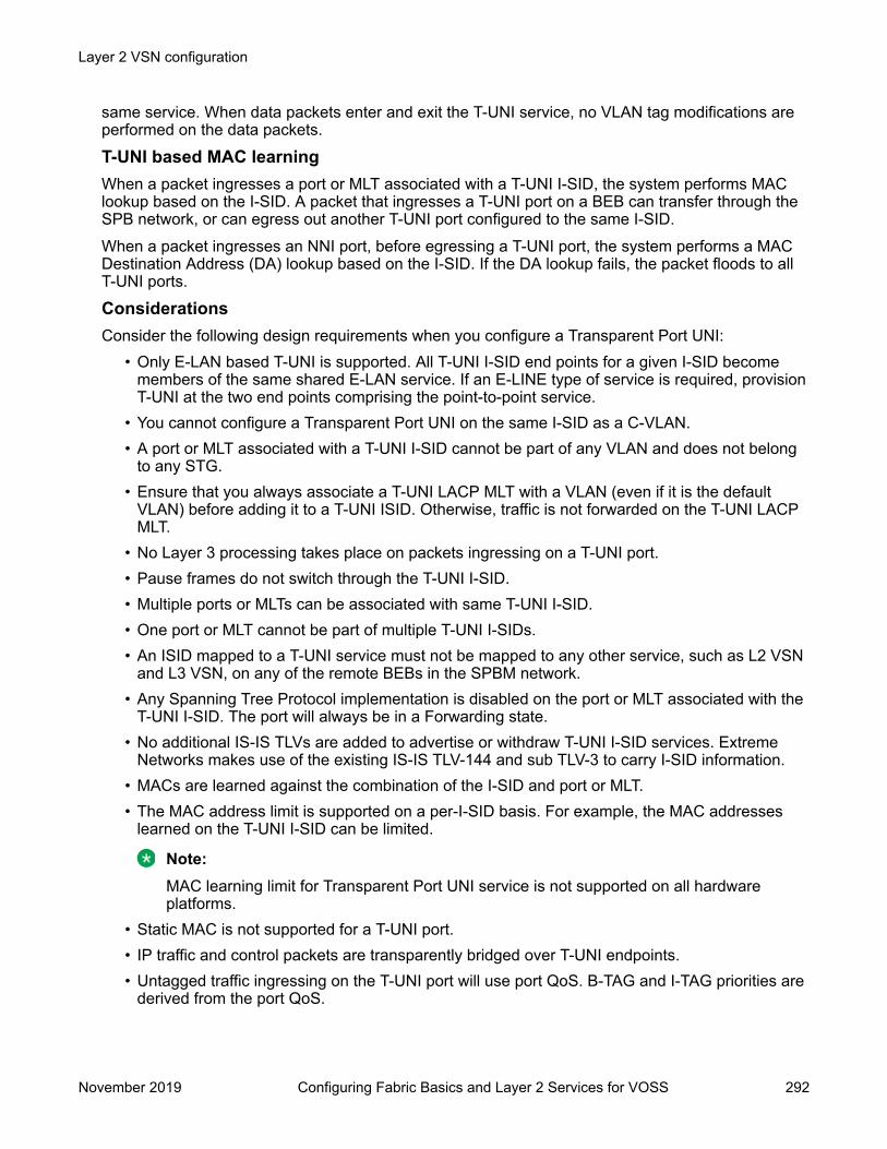
same service. When data packets enter and exit the T-UNI service, no VLAN tag modifications areperformed on the data packets.
T-UNI based MAC learningWhen a packet ingresses a port or MLT associated with a T-UNI I-SID, the system performs MAClookup based on the I-SID. A packet that ingresses a T-UNI port on a BEB can transfer through theSPB network, or can egress out another T-UNI port configured to the same I-SID.When a packet ingresses an NNI port, before egressing a T-UNI port, the system performs a MACDestination Address (DA) lookup based on the I-SID. If the DA lookup fails, the packet floods to allT-UNI ports.
ConsiderationsConsider the following design requirements when you configure a Transparent Port UNI:
• Only E-LAN based T-UNI is supported. All T-UNI I-SID end points for a given I-SID becomemembers of the same shared E-LAN service. If an E-LINE type of service is required, provisionT-UNI at the two end points comprising the point-to-point service.
• You cannot configure a Transparent Port UNI on the same I-SID as a C-VLAN.• A port or MLT associated with a T-UNI I-SID cannot be part of any VLAN and does not belong
to any STG.• Ensure that you always associate a T-UNI LACP MLT with a VLAN (even if it is the default
VLAN) before adding it to a T-UNI ISID. Otherwise, traffic is not forwarded on the T-UNI LACPMLT.
• No Layer 3 processing takes place on packets ingressing on a T-UNI port.• Pause frames do not switch through the T-UNI I-SID.• Multiple ports or MLTs can be associated with same T-UNI I-SID.• One port or MLT cannot be part of multiple T-UNI I-SIDs.• An ISID mapped to a T-UNI service must not be mapped to any other service, such as L2 VSN
and L3 VSN, on any of the remote BEBs in the SPBM network.• Any Spanning Tree Protocol implementation is disabled on the port or MLT associated with the
T-UNI I-SID. The port will always be in a Forwarding state.• No additional IS-IS TLVs are added to advertise or withdraw T-UNI I-SID services. Extreme
Networks makes use of the existing IS-IS TLV-144 and sub TLV-3 to carry I-SID information.• MACs are learned against the combination of the I-SID and port or MLT.• The MAC address limit is supported on a per-I-SID basis. For example, the MAC addresses
learned on the T-UNI I-SID can be limited.
Note:MAC learning limit for Transparent Port UNI service is not supported on all hardwareplatforms.
• Static MAC is not supported for a T-UNI port.• IP traffic and control packets are transparently bridged over T-UNI endpoints.• Untagged traffic ingressing on the T-UNI port will use port QoS. B-TAG and I-TAG priorities are
derived from the port QoS.
Layer 2 VSN configuration
November 2019 Configuring Fabric Basics and Layer 2 Services for VOSS 292
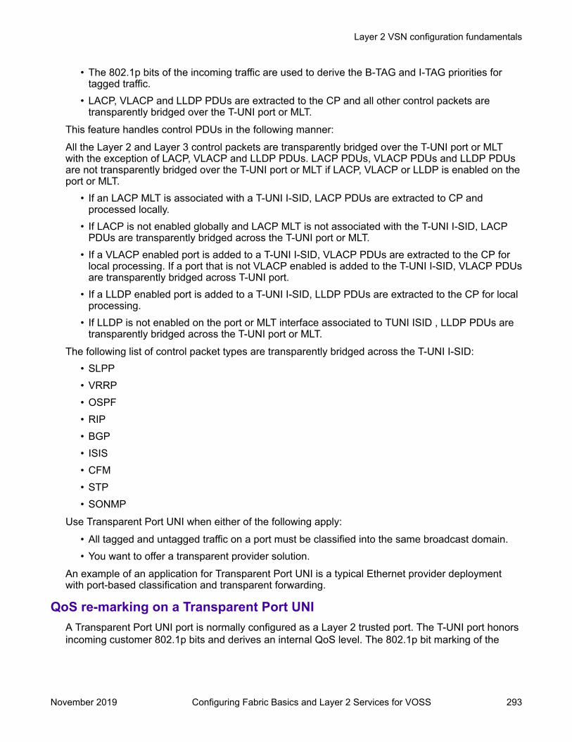
• The 802.1p bits of the incoming traffic are used to derive the B-TAG and I-TAG priorities fortagged traffic.
• LACP, VLACP and LLDP PDUs are extracted to the CP and all other control packets aretransparently bridged over the T-UNI port or MLT.
This feature handles control PDUs in the following manner:All the Layer 2 and Layer 3 control packets are transparently bridged over the T-UNI port or MLTwith the exception of LACP, VLACP and LLDP PDUs. LACP PDUs, VLACP PDUs and LLDP PDUsare not transparently bridged over the T-UNI port or MLT if LACP, VLACP or LLDP is enabled on theport or MLT.
• If an LACP MLT is associated with a T-UNI I-SID, LACP PDUs are extracted to CP andprocessed locally.
• If LACP is not enabled globally and LACP MLT is not associated with the T-UNI I-SID, LACPPDUs are transparently bridged across the T-UNI port or MLT.
• If a VLACP enabled port is added to a T-UNI I-SID, VLACP PDUs are extracted to the CP forlocal processing. If a port that is not VLACP enabled is added to the T-UNI I-SID, VLACP PDUsare transparently bridged across T-UNI port.
• If a LLDP enabled port is added to a T-UNI I-SID, LLDP PDUs are extracted to the CP for localprocessing.
• If LLDP is not enabled on the port or MLT interface associated to TUNI ISID , LLDP PDUs aretransparently bridged across the T-UNI port or MLT.
The following list of control packet types are transparently bridged across the T-UNI I-SID:• SLPP• VRRP• OSPF• RIP• BGP• ISIS• CFM• STP• SONMP
Use Transparent Port UNI when either of the following apply:• All tagged and untagged traffic on a port must be classified into the same broadcast domain.• You want to offer a transparent provider solution.
An example of an application for Transparent Port UNI is a typical Ethernet provider deploymentwith port-based classification and transparent forwarding.
QoS re-marking on a Transparent Port UNIA Transparent Port UNI port is normally configured as a Layer 2 trusted port. The T-UNI port honorsincoming customer 802.1p bits and derives an internal QoS level. The 802.1p bit marking of the
Layer 2 VSN configuration fundamentals
November 2019 Configuring Fabric Basics and Layer 2 Services for VOSS 293
Backbone VLAN (BVLAN) is derived from the internal QoS level. If the T-UNI port is set as a Layer 2untrusted port, a best-effort queue is assigned. Customer packet headers are not modified.
The T-UNI port QoS configurations are:
• DiffServ = disable
• Layer3Trusted = access (for EDM configuration)
• access-diffserv enable (for CLI configuration)
QoS considerations when a port is associated with a T-UNI I-SID• You cannot configure access-diffserv and enable diffserv on a T-UNI port.
• When a port is associated with a T-UNI ISID, the T-UNI QoS configuration automatically takeseffect.
• When the port is removed from the T-UNI ISID, the default port QoS configuration takes effect.
QoS considerations when an MLT is associated with a T-UNI I-SID• When an MLT, static or LACP, is added to a T-UNI ISID, the T-UNI QoS configuration take
effect on all the ports of the MLT.• When an MLT, static or LACP, is removed from a T-UNI ISID, the port default QoS configuration
is configured on all the member ports of the MLT.• If a port is added dynamically to a T-UNI MLT, static or LACP, the port inherits the QoS
properties of the T-UNI MLT ports.• If a port is dynamically removed from a T-UNI MLT, static or LACP, the port retains the QoS
configuration inherited from the MLT.
Transparent Port UNI over vISTVirtual IST (vIST) provides the ability to dual-home hosts, servers and other network devices to apair of Multi-Chassis Link Aggregation (MC-LAG) enabled devices. The MC-LAG nodes appear tothe connected devices as one link-aggregated group. So, although the physical connection isspread between two individual network nodes, logically they appear as a single connection.
Transparent Port UNI (T-UNI) over vIST peers extends the capability of dual-home hosts on theSPB cloud to achieve higher network resiliency. The MACs learnt on the T-UNI interface of any onevIST peer is synchronized with the other peer through MAC synchronization.
In the following figure, the T-UNI access switch ACCESS-1 is dual-homed into vIST peer hostsVIST-PEER 1 and VIST-PEER 2. At ACCESS-1, a link aggregation is created to connect to theSPBM cluster. On the VIST peers, an SMLT is created towards ACCESS-1. Depending on the linkaggregation hashing logic, traffic is hashed on to VIST-PEER 1 and VIST-PEER 2. The MACs learnton the T-UNI interfaces of either host is synchronized with the other host.
Layer 2 VSN configuration
November 2019 Configuring Fabric Basics and Layer 2 Services for VOSS 294

Figure 40: Example of Transparent Port UNI over vIST
If one of the links between ACCESS-1 and the vIST cluster goes down, all traffic is serviced throughthe other link. The same applies when any of the vIST peers go down. Since MAC learning on bothpeers are synchronized, both peers can switch traffic with the same efficiency.
Single-homed T-UNI service on a vIST-enabled nodeIf you configure a T-UNI service as a single-homed service on a vIST-enabled node, you mustconfigure the same ISID service without port/MLT being mapped to ISID, on the other vIST peernode. Failure to perform this configuration on the vIST peer node can result in the loss of traffic tothe single-homed T-UNI service in various scenarios.
Switched UNISwitched User Network Interface (S-UNI) allows the association of local endpoints to I-SIDs basedon local port and VLAN together. With Switched UNI, the same VLAN can be used on one port tocreate an endpoint to one I-SID, and on another port to create an endpoint to another I-SID.
Switched UNI summary:
• Switched UNI is a VLAN and ports associated with I-SIDs.
• Local significance on the ports.
• You can re-use the same VLAN to associate different ports with different I-SIDs.
• You can use a different VLAN to the same ports, or you can assign different ports to the sameI-SID.
• Supports VLAN mapping on the local switch.
• To accept untagged traffic, the port needs to be configured as untagged-traffic in the I-SID.
Use Switched UNI when either of the following apply:
• Vlan ID (VID) reuse is required. The same VID is used on different broadcast domains (multi-tenant applications).
• Multiple VLANs must be part of the same broadcast domain.
• VID translation is required.
An example of an application for Switched UNI is a typical host and provider deployment, with a portand VID-based classification.
Layer 2 VSN configuration fundamentals
November 2019 Configuring Fabric Basics and Layer 2 Services for VOSS 295

Switched UNI based MAC learningMAC learning is done on I-SID MAC. When a packet ingresses on a port or MLT which is associatedwith Switched UNI I-SID, the system performs MAC look up based on the I-SID. Switched UNIoperates on Any-To-Any (ELAN) mode, there can be one or more ports associated to a SwitchedUNI I-SID. A packet that ingresses to a Switched UNI port on a BEB can transfer through the SPBMcloud, or can egress out another Switched UNI port configured to the same I-SID.When a packet ingresses an NNI port, before egressing a Switched UNI port, the system performs aMAC Destination Address (DA) lookup based on the I-SID. If the DA lookup fails, the packet floodsto all Switched UNI ports in the I-SID.
ConsiderationsConsider the following when you configure a Switched UNI:
• The VLAN tag is removed before the traffic egresses out on the untagged-traffic port or MLT.• VLAN priority received on the packet is maintained across VLAN IDs.• Spanning tree is disabled on all Switched UNI ports, and the ports remain in forwarding state.• The Switched UNI I-SID is advertised to the SPBM cloud.• The Broadcast and unknown Unicast packets are flooded to all ports in the I-SID.
Limitations• You cannot change from one UNI type to another dynamically. The I-SID has to be deleted and
created with new UNI type (Customer VLAN (C-VLAN), Transparent port user-network-interface (T-UNI), ELAN).
• I-SID cannot be used by IPVPN, MVPN, SPBM dynamic multicast range, or Transparent PortUNI.
• If the port is a member of MLT, the entire MLT has to be added to the VID.• The port is always in the forwarding state.• The same VID, port, or MLT cannot be member of more than one I-SID.• Static MAC, Static ARP and static IGMP group are not supported on Switched UNI enabled
ports.• For a Switched UNI endpoint without a platform VLAN on the VSP 7400 Series, when MAC-in-
MAC terminated traffic is sent out to the UNI endpoint the packet is re-marked based onexisting QoS rules.
BPDU handling on S-UNI port/MLTThe switch handles Bridge Protocol Data Units (BPDUs) according to whether or not you configure aplatform VLAN.
• When you configure a platform VLAN:- BPDUs are forwarded to the CPU by default.- For both the ingress and egress ports, BPDUs are not flooded in the S-UNI I-SID associated
with the platform VLAN.
Layer 2 VSN configuration
November 2019 Configuring Fabric Basics and Layer 2 Services for VOSS 296

Note:If the platform VLAN is configured for the S-UNI port, you cannot enable BDPU forwarding.
• When you DO NOT configure a platform VLAN:- BPDUs received on untagged-traffic ports are dropped by default.- To flood BPDUs in its I-SID, enable BPDU forwarding under S-UNI I-SID using the commanduntagged-traffic port <port no> bpdu enable.
SPBM sample operation—L2 VSNThe following section shows how a SPBM network is established, in this case, a Layer 2 VSN.
1. Discover network topology
Figure 41: SPBM topology discover
Layer 2 VSN configuration fundamentals
November 2019 Configuring Fabric Basics and Layer 2 Services for VOSS 297
IS-IS runs on all nodes of the SPBM domain. Since IS-IS is the basis of SPBM, the IS-ISadjacency must be formed first. After the neighboring nodes see hellos from each other theylook for the same Level (Level 1) and the same area (for example, Area 2f.8700.0000.00).After the hellos are confirmed both nodes send Link State Protocol Data Units, which containconnectivity information for the SPBM node. These nodes also send copies of all other LSPsthey have in their databases. This establishes a network of connectivity providing thenecessary information for each node to find the best and proper path to all destinations in thenetwork.Each node has a system ID, which is used in the topology announcement. This sameSystem ID also serves as the switch Backbone MAC address (B-MAC), which is used as thesource and destination MAC address in the SPBM network.
2. Each IS-IS node automatically builds trees from itself to all other nodes
When the network topology is discovered and stored in the IS-IS link state database (LSDB),each node calculates shortest path trees for each source node. A unicast path now existsfrom every node to every other nodeWith this information, each node populates unicast information received from SPBM into theFIB for forwarding purposes. Multicast FIB is not produced until Layer 2 VSN services areconfigured and learned.
3. IS-IS advertises new service communities of interest
When a new service is provisioned, its membership is flooded throughout the topology withan IS-IS advertisement.
Layer 2 VSN configuration
November 2019 Configuring Fabric Basics and Layer 2 Services for VOSS 298

Figure 42: SPBM BMAC and I-SID population
BMAC and I-SID information is flooded throughout the network to announce new I-SIDmemberships. In this case, VLAN 20 is mapped to I-SID 100.
Note:I-SIDs are only used for virtual services (Layer 2 and Layer 3 VSNs). If IP Shortcuts onlyis enabled on the BEBs, I-SIDs are never exchanged in the network as IP Shortcutsallow for IP networks to be transported across IS-IS.
Each node populates its FDB with the BMAC information derived from the IS-IS shortestpath tree calculations. Thus there is no traditional flooding and learning mechanism in placefor the B-VLAN, but FDBs are programmed by the IS-IS protocol.
4. When a node receives notice of a new service AND is on the shortest path, it updates theFDB
In this scenario, where there are three source nodes having a membership on I-SID 100,there are three shortest path trees calculated (not counting the Equal Cost Trees (ECTs).
Layer 2 VSN configuration fundamentals
November 2019 Configuring Fabric Basics and Layer 2 Services for VOSS 299

Figure 43: Shortest path tree for source node A
Layer 2 VSN configuration
November 2019 Configuring Fabric Basics and Layer 2 Services for VOSS 300

Figure 44: Shortest path tree for source node B
Layer 2 VSN configuration fundamentals
November 2019 Configuring Fabric Basics and Layer 2 Services for VOSS 301

Figure 45: Shortest path tree for source node C
The paths between any two nodes are always the shortest paths. Also, the paths in eitherdirection are congruent, thus a bidirectional communication stream can be monitored easilyby mirroring ingress and egress on a link to a network analyzer.VLAN traffic arriving on switch A and VLAN 20 is forwarded following the blue path, trafficarriving on switch B and VLAN 20 the orange path and on switch C VLAN 20 traffic isfollowing the green path.If the destination CMAC is unknown at the SPBM ingress node or the traffic is of typebroadcast or multicast, then it is flooded to all members of the topology which spans VLAN20. If the destination CMAC is already known, then the traffic is only forwarded as a unicastto the appropriate destination. In the SPBM domain, the traffic is switched on the BMACheader only. The bridge filtering database (FDB) at the VLAN to I-SID boundary (backboneedge bridge BEB), maintains a mapping between CMACs and corresponding BMACs.For example, Switch B learns all CMACs which are on VLAN 20 connected to switch A withthe BMAC of A in its FDB and the CMACs which are behind C are learned with the BMAC ofC.
Layer 2 VSN configuration
November 2019 Configuring Fabric Basics and Layer 2 Services for VOSS 302

Layer 2 VSN configuration using the CLIThis section provides procedures to configure Layer 2 VSNs using the CLI.
Configuring SPBM Layer 2 VSNSPBM supports Layer 2 Virtual Service Network (VSN) functionality where customer VLANs (C-VLANs) are bridged over the SPBM core infrastructure.
At the BEBs, customer VLANs (C-VLAN) are mapped to I-SIDs based on the local serviceprovisioning. Outgoing frames are encapsulated in a MAC-in-MAC header, and then forwardedacross the core to the far-end BEB, which strips off the encapsulation and forwards the frame to thedestination network based on the I-SID-to-C-VLAN provisioning.
Before you begin• You must configure the required SPBM and IS-IS infrastructure, which includes the creation of
SPBM BVLANs.• You must create the customer VLANs (C-VLANs) and add slots/ports.
Procedure1. Enter Global Configuration mode:
enableconfigure terminal
2. Map a customer VLAN (C-VLAN) to a Service Instance Identifier (I-SID):
vlan i-sid <1-4059> <0–16777215>Important:
When a protocol VLAN is created, all ports are added to the VLAN including SPBMports. To configure a protocol-based VLAN as a C-VLAN, you must first remove theSPBM-enabled ports from the protocol based VLAN, and then configure the protocol-based VLAN as a C-VLAN.
The switch reserves I-SID 0x00ffffff. The switch uses this I-SID to advertise the virtual B-MAC in a SMLT dual-homing environment. The platform clears the receive and transmitbit of this I-SID, therefore I-SID 0x00ffffff cannot be used for any other service.
3. Display C-VLAN information:
show vlan i-sidExampleSwitch> enableSwitch# configure terminalSwitch:1(config)# vlan i-sid 5 5
Layer 2 VSN configuration using the CLI
November 2019 Configuring Fabric Basics and Layer 2 Services for VOSS 303
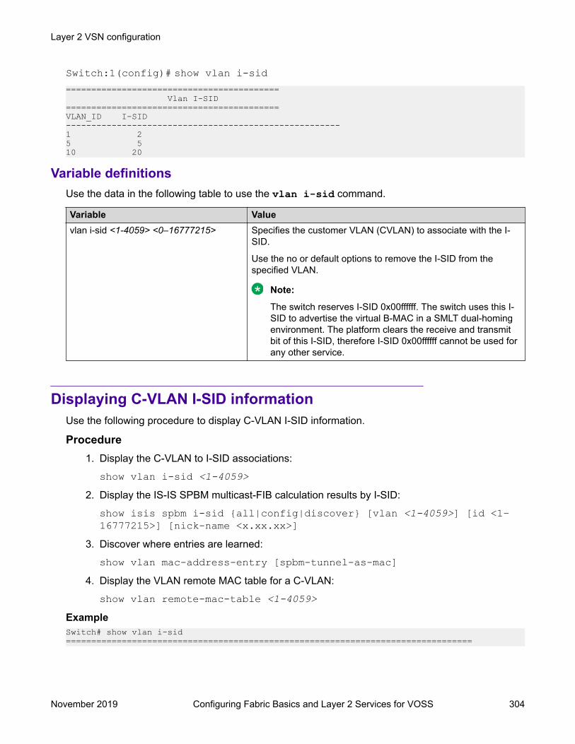
Switch:1(config)# show vlan i-sid========================================== Vlan I-SID ==========================================VLAN_ID I-SID ------------------------------------------------------1 2 5 5 10 20
Variable definitionsUse the data in the following table to use the vlan i-sid command.
Variable Valuevlan i-sid <1-4059> <0–16777215> Specifies the customer VLAN (CVLAN) to associate with the I-
SID.
Use the no or default options to remove the I-SID from thespecified VLAN.
Note:
The switch reserves I-SID 0x00ffffff. The switch uses this I-SID to advertise the virtual B-MAC in a SMLT dual-homingenvironment. The platform clears the receive and transmitbit of this I-SID, therefore I-SID 0x00ffffff cannot be used forany other service.
Displaying C-VLAN I-SID informationUse the following procedure to display C-VLAN I-SID information.
Procedure1. Display the C-VLAN to I-SID associations:
show vlan i-sid <1-4059>2. Display the IS-IS SPBM multicast-FIB calculation results by I-SID:
show isis spbm i-sid {all|config|discover} [vlan <1-4059>] [id <1–16777215>] [nick-name <x.xx.xx>]
3. Discover where entries are learned:
show vlan mac-address-entry [spbm-tunnel-as-mac]4. Display the VLAN remote MAC table for a C-VLAN:
show vlan remote-mac-table <1-4059>ExampleSwitch# show vlan i-sid================================================================================
Layer 2 VSN configuration
November 2019 Configuring Fabric Basics and Layer 2 Services for VOSS 304

Vlan I-SID================================================================================VLAN_ID I-SID --------------------------------------------------------------------------------1 2 5 5 10 20 Switch# show isis spbm i-sid all================================================================================ SPBM ISID INFO================================================================================ISID SOURCE NAME VLAN SYSID TYPE HOST_NAME--------------------------------------------------------------------------------200 1.11.16 1000 0014.c7e1.33df config SwitchA 300 1.11.16 1000 0014.c7e1.33df config SwitchA 400 1.11.16 1000 0014.c7e1.33df config SwitchA 200 1.11.16 2000 0014.c7e1.33df config SwitchA 300 1.11.16 2000 0014.c7e1.33df config SwitchA 400 1.11.16 2000 0014.c7e1.33df config SwitchA 200 1.12.45 1000 0016.ca23.73df discover SwitchA 300 1.12.45 1000 0016.ca23.73df discover SwitchA
-------------------------------------------------------------------------------- Total number of SPBM ISID entries configed: 6-------------------------------------------------------------------------------- Total number of SPBM ISID entries discovered: 2-------------------------------------------------------------------------------- Total number of SPBM ISID entries: 8--------------------------------------------------------------------------------
Switch:# show vlan mac-address-entry================================================================================ Vlan Fdb================================================================================VLAN MAC SMLTID STATUS ADDRESS INTERFACE REMOTE TUNNEL--------------------------------------------------------------------------------1 learned 00:1d:42:6b:10:03 Port-1/9 false SwitchB1 learned 00:80:2d:22:ac:46 Port-1/15 false SwitchB2 self a4:25:1b:51:48:84 103.103.103.103 false -2 self 02:01:03:ff:ff:ff Tunnel_to_HQ false -5 learned 00:00:00:00:00:1a access false SwitchB10 self 00:00:00:00:49:50 Port-1/9 false —10 self 00:00:00:50:00:50 Port-1/9 false —Switch# show vlan remote-mac-table 100========================================================================================== Vlan Remote Mac Table==========================================================================================VLAN STATUS MAC-ADDRESS DEST-MAC BVLAN DEST-SYSNAME PORTS SMLTREMOTE------------------------------------------------------------------------------------------100 learned 00:15:40:af:d2:00 00:74:00:00:00:00 20 Switch-6005 MLT-2 false100 learned b4:a9:5a:04:c8:83 b4:a9:5a:04:c8:65 3 Switch-174 103.103.103.103 true100 learned b4:a9:5a:04:c8:84 b4:a9:5a:04:c8:66 3 Switch-175 Tunnel_to_HQ true------------------------------------------------------------------------------------------3 of 3 matching entries out of total of 3 Remote Mac entries in all fdb(s) displayed.------------------------------------------------------------------------------------------
Variable definitionsUse the data in the following table to use the show vlan commands.
Layer 2 VSN configuration using the CLI
November 2019 Configuring Fabric Basics and Layer 2 Services for VOSS 305

Variable Valuei-sid <1-4059> Displays I-SID information for the specified C-VLAN.mac-address-entry [spbm-tunnel-as-mac] Displays the bridging forwarding database.
Use the optional parameter, spbm-tunnel-as-mac to display theBMAC in the TUNNEL column. If you do not use this optionalparameter, the TUNNEL column displays the host name. If anentry is not learned in the SPBM network, the TUNNEL columnwill be empty (–).
remote-mac-table <1-4059> Displays C-VLAN remote-mac-table information.
Use the data in the following table to use the show isis commands.
Variable Valuespbm i-sid {all|config|discover} • all: displays all I-SID entries
• config: displays configured I-SID entries
• discover: displayes discovered I-SID entriesvlan <1-4059> Displays I-SID information for the specified SPBM VLAN.id <1–16777215> Displays I-SID information for the specified I-SID.nick-name <x.xx.xx> Displays I-SID information for the specified nickname.
Job aidThe following sections describe the fields in the outputs for the C-VLAN I-SID show commands.
show vlan i-sidThe following table describes the fields in the output for the show vlan i-sid command.
Parameter DescriptionVLAN_ID Indicates the VLAN IDs.I-SID Indicates the I-SIDs associated with the specified C-
VLANs.
show isis spbm i-sidThe following describes the fields in the output for the show isis spbm i-sid command.
Parameter DescriptionISID Indicates the IS-IS SPBM I-SID identifier.SOURCE NAME Indicates the nickname of the node where this I-SID
was configured or discovered.
Note:
SOURCE NAME is equivalent to nickname.
Table continues…
Layer 2 VSN configuration
November 2019 Configuring Fabric Basics and Layer 2 Services for VOSS 306

Parameter DescriptionVLAN Indicates the B-VLAN where this I-SID was
configured or discovered.SYSID Indicates the system identifier.TYPE Indicates the SPBM I-SID type as either configured
or discovered.HOST_NAME Indicates the host name of the multicast FIB entry.
show vlan mac-address-entryThe following table describes the fields in the output for the show vlan mac-address-entrycommand.
Parameter DescriptionVLAN ID Indicates the VLAN for this MAC address.STATUS Indicates the status of this entry:
• other
• invalid
• learned
• self
• mgmtMAC ADDRESS Indicates the MAC address.INTERFACE Displays the network-to-network (NNI) interface.SMLT REMOTE Indicates the MAC address entry for the remote vIST
peer.TUNNEL Indicates the host name of the remote Backbone
Edge Bridge (BEB).
show vlan remote-mac-tableThe following table describes the fields in the output for the show vlan remote-mac-tablecommand.
Parameter DescriptionVLAN Indicates the VLAN ID for this MAC address.STATUS Indicates the status of this entry:
• other
• invalid
• learned
• self
• mgmt
Table continues…
Layer 2 VSN configuration using the CLI
November 2019 Configuring Fabric Basics and Layer 2 Services for VOSS 307

Parameter DescriptionMAC-ADDRESS Indicates the customer MAC address for which the
bridge has forwarding and/or filtering information.DEST-MAC Indicates the provide MAC address for which the
bridge has forwarding and/or filtering information.BVLAN Indicates the B-VLAN ID for this MAC address.DEST-SYSNAME Indicates the system name of the node where the
MAC address entry comes from.PORTS Either displays the value 0 or indicates the port in
which a frame comes from.SMLT REMOTE Indicates the MAC address entry for the remote vIST
peer.
Configuring an SPBM Layer 2 Transparent Port UNIUse this procedure to configure a Transparent Port UNI or E-LAN Transparent service.
Note:
If you are configuring a T-UNI to terminate on a port or MLT on a switch in a vIST switch cluster,you must also configure the T-UNI I-SID on the other switch of the vIST switch cluster. You mustconfigure the T-UNI I-SID on both switches of a vIST pair. It is not necessary to assign an actualport or MLT to the T-UNI on the second switch.
Before you begin• You must configure the required SPBM and IS-IS infrastructure, which includes creating the
SPBM BVLANs.• You must associate a T-UNI LACP MLT with a VLAN before mapping the LACP MLT to a T-UNI
I-SID.
Caution:In the case of T-UNI LACP SMLT, before you configure SMLT on switch peers, ensure thatthe T-UNI LACP MLT on each peer is always associated with a VLAN, even if it is thedefault VLAN, and that it is added to a T-UNI I-SID. Otherwise, traffic is not forwarded onthe T-UNI LACP MLT.
About this taskYou can configure Transparent Port UNI when either of the following apply:
• You want all tagged and untagged traffic on a port to be classified into the same broadcastdomain.
• You want to offer a transparent provider solution.
Procedure1. Enter Global Configuration mode:
Layer 2 VSN configuration
November 2019 Configuring Fabric Basics and Layer 2 Services for VOSS 308
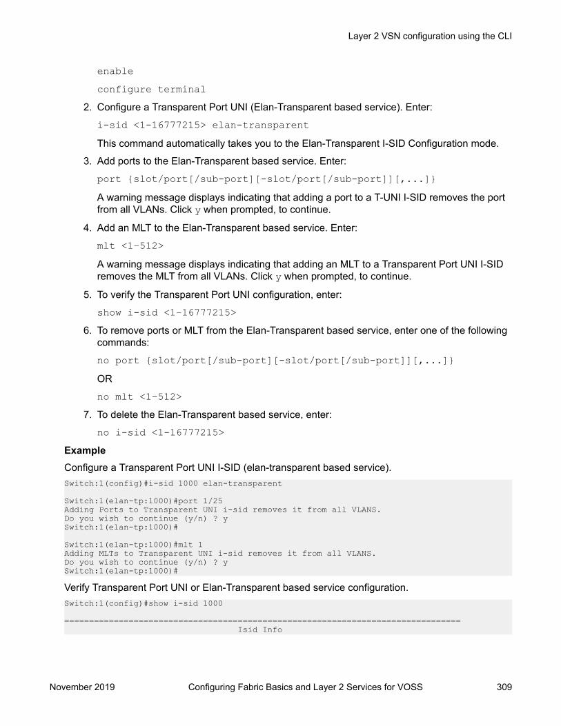
enableconfigure terminal
2. Configure a Transparent Port UNI (Elan-Transparent based service). Enter:
i-sid <1-16777215> elan-transparentThis command automatically takes you to the Elan-Transparent I-SID Configuration mode.
3. Add ports to the Elan-Transparent based service. Enter:
port {slot/port[/sub-port][-slot/port[/sub-port]][,...]}A warning message displays indicating that adding a port to a T-UNI I-SID removes the portfrom all VLANs. Click y when prompted, to continue.
4. Add an MLT to the Elan-Transparent based service. Enter:
mlt <1–512>A warning message displays indicating that adding an MLT to a Transparent Port UNI I-SIDremoves the MLT from all VLANs. Click y when prompted, to continue.
5. To verify the Transparent Port UNI configuration, enter:
show i-sid <1–16777215>6. To remove ports or MLT from the Elan-Transparent based service, enter one of the following
commands:
no port {slot/port[/sub-port][-slot/port[/sub-port]][,...]}OR
no mlt <1–512>7. To delete the Elan-Transparent based service, enter:
no i-sid <1-16777215>ExampleConfigure a Transparent Port UNI I-SID (elan-transparent based service).Switch:1(config)#i-sid 1000 elan-transparent
Switch:1(elan-tp:1000)#port 1/25Adding Ports to Transparent UNI i-sid removes it from all VLANS.Do you wish to continue (y/n) ? ySwitch:1(elan-tp:1000)#
Switch:1(elan-tp:1000)#mlt 1Adding MLTs to Transparent UNI i-sid removes it from all VLANS.Do you wish to continue (y/n) ? ySwitch:1(elan-tp:1000)#
Verify Transparent Port UNI or Elan-Transparent based service configuration.Switch:1(config)#show i-sid 1000
================================================================================ Isid Info
Layer 2 VSN configuration using the CLI
November 2019 Configuring Fabric Basics and Layer 2 Services for VOSS 309

================================================================================ PORT MLT ISID ISID PORT MLTID TYPE VLANID INTERFACES INTERFACES ORIGIN----------------------------------------------------------------------------------1000 ELAN_TR N/A 2/19,8/23 1,5-6,20,30 CONFIG
Variable definitionsUse the data in the following table to use the i-sid command.
Note:When SPB is enabled, ISID IDs 16000000 (0xF42400) and greater, up to 16,777,215(0xFFFFFF), are reserved for dynamic i-sid allocation and used to support IP Multicast trafficover SPB and other advanced Fabric services.
Variable Valuei-sid <1–16777215> elan-transparent Creates an Elan-Transparent based service. The service
interface identifier (I-SID) range is 1 to 16777215.port {slot/port[/sub-port][-slot/port[/sub-port]][,...]}
Add ports to the Elan-Transparent based service.
mlt<1–512> Add MLTs to the Elan-Transparent based service. The MLTrange is 1 to 512.
Viewing all Configured I-SIDsPerform this procedure to view all the configured I-SIDs including their types, ports, and MLTs.
About this taskView all configured I-SIDs (both CVLAN and T-UNI). View also the I-SID types and the ports or MLTsthat are assigned to each I-SID.
Procedure1. Enter Privileged EXEC mode:
enable2. View all configured I-SIDs. This command displays both CVLAN and T-UNI based I-SIDs.
show i-sid3. View all T-UNI (Elan-Transparent) I-SIDs.
show i-sid [elan-transparent]4. View information for a particular T-UNI I-SID.
show i-sid [<1–16777215>]5. View all IS-IS SPBM I-SID information by I-SID ID:
Layer 2 VSN configuration
November 2019 Configuring Fabric Basics and Layer 2 Services for VOSS 310

show isis spbm i-sid {all|config|discover} [vlan <2-4059>] [id <1–16777215>] [nick-name <x.xx.xx>]
ExampleView all configured I-SIDs.Switch:1(config)#show i-sid================================================================================ Isid Info================================================================================ ISID ISID PORT MLT ID TYPE VLANID INTERFACES INTERFACES ORIGIN----------------------------------------------------------------------------------2 CVLAN 2 - - CONFIG 111 ELAN_TR N/A 1/2-1/8,8/11 111 CONFIG 1000 ELAN_TR N/A 2/19,8/23 1,5-6,20,30 CONFIG 10001 ELAN 1000 - - CONFIG
c: customer vid u: untagged-traffic
All 4 out of 4 Total Num of i-sids displayed
View T-UNI (ELAN Transparent) I-SIDs.Switch:1(config)#show i-sid elan-transparent================================================================================ Isid Info================================================================================ISID ISID PORT MLTID TYPE VLANID INTERFACES INTERFACES--------------------------------------------------------------------------------100 ELAN_TR N/A 1/126 ELAN_TR N/A 1/2
All 2 out of 2 Total Num of elan-tp i-sids displayed
View MLT or port information for a particular T-UNI I-SID.Switch:1(config)#show i-sid 111
================================================================================ Isid Info================================================================================ PORT MLT ISID ISID PORT MLTID TYPE VLANID INTERFACES INTERFACES ORIGIN----------------------------------------------------------------------------------111 ELAN_TR N/A 1/2-1/8,8/11 111 CONFIG
View all IS-IS SPBM I-SID information:Switch:1#show isis spbm i-sid all
================================================================================ SPBM ISID INFO================================================================================ISID SOURCE NAME VLAN SYSID TYPE HOST_NAME--------------------------------------------------------------------------------100 1.11.16 20 0014.c7e1.33df config Switch16 1.11.20 10 0014.c723.67df discover Switch2-------------------------------------------------------------------------------- Total number of SPBM ISID entries configured: 1--------------------------------------------------------------------------------
Layer 2 VSN configuration using the CLI
November 2019 Configuring Fabric Basics and Layer 2 Services for VOSS 311
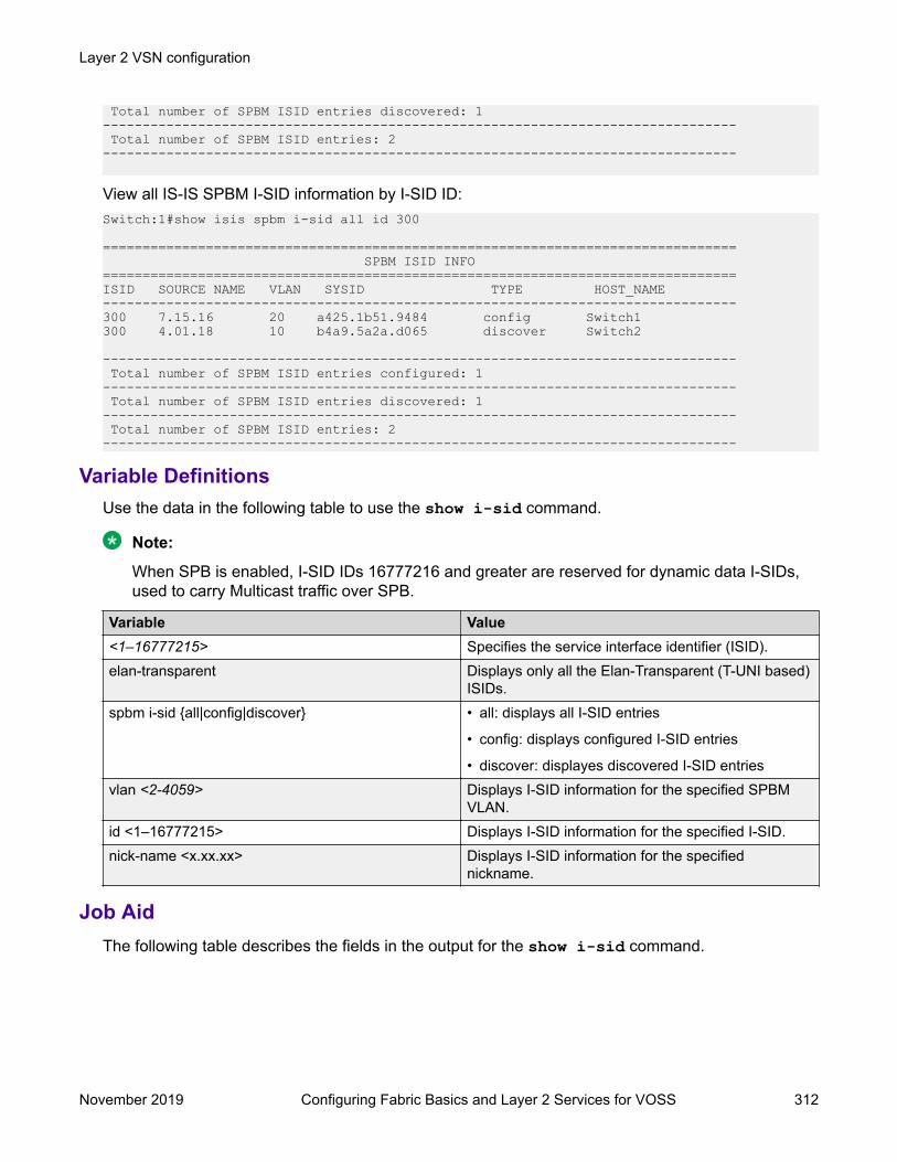
Total number of SPBM ISID entries discovered: 1-------------------------------------------------------------------------------- Total number of SPBM ISID entries: 2--------------------------------------------------------------------------------
View all IS-IS SPBM I-SID information by I-SID ID:Switch:1#show isis spbm i-sid all id 300
================================================================================ SPBM ISID INFO================================================================================ISID SOURCE NAME VLAN SYSID TYPE HOST_NAME--------------------------------------------------------------------------------300 7.15.16 20 a425.1b51.9484 config Switch1300 4.01.18 10 b4a9.5a2a.d065 discover Switch2
-------------------------------------------------------------------------------- Total number of SPBM ISID entries configured: 1-------------------------------------------------------------------------------- Total number of SPBM ISID entries discovered: 1-------------------------------------------------------------------------------- Total number of SPBM ISID entries: 2--------------------------------------------------------------------------------
Variable DefinitionsUse the data in the following table to use the show i-sid command.
Note:
When SPB is enabled, I-SID IDs 16777216 and greater are reserved for dynamic data I-SIDs,used to carry Multicast traffic over SPB.
Variable Value<1–16777215> Specifies the service interface identifier (ISID).elan-transparent Displays only all the Elan-Transparent (T-UNI based)
ISIDs.spbm i-sid {all|config|discover} • all: displays all I-SID entries
• config: displays configured I-SID entries
• discover: displayes discovered I-SID entriesvlan <2-4059> Displays I-SID information for the specified SPBM
VLAN.id <1–16777215> Displays I-SID information for the specified I-SID.nick-name <x.xx.xx> Displays I-SID information for the specified
nickname.
Job AidThe following table describes the fields in the output for the show i-sid command.
Layer 2 VSN configuration
November 2019 Configuring Fabric Basics and Layer 2 Services for VOSS 312

Table 27: show i-sid
Field DescriptionISID ID Specifies the service interface identifier (I-SID)ISID TYPE Specifies the type of I-SIDVLANID Specifies the backbone VLANPORT INTERFACES Specifies the port that is assigned to the I-SIDMLT INTERFACES Specifies the mlt that is assigned to the I-SID
The following describes the fields in the output for the show isis spbm i-sid command.
Table 28: show isis spbm i-sid
Field DescriptionISID Indicates the IS-IS SPBM I-SID identifier.SOURCE NAME Indicates the nickname of the node where this I-SID
was configured or discovered.
Note:
SOURCE NAME is equivalent to nickname.VLAN Indicates the B-VLAN where this I-SID was
configured or discovered.SYSID Indicates the system identifier.TYPE Indicates the SPBM I-SID type as either configured
or discovered.HOST_NAME Indicates the host name of the multicast FIB entry.
Viewing C-MACs Learned on T-UNI Ports for an I-SIDPerform this procedure to view the I-SID bridge forwarding database.
About this taskThe show i-sid mac-address-entry command displays the C-MACs learned on T-UNI I-SIDs.It also displays the C-MACs learned on T-UNI I-SIDs for a specific I-SID, MAC address, port or portlist or remote MAC address.
Procedure1. To enter User EXEC mode, log on to the switch.
2. View C-MACs learned on the T-UNI I-SIDs:
show i-sid mac-address-entry [<1-16777215>] [mac<0x00:0x00:0x00:0x00:0x00:0x00>] [port {slot/port[/sub-port] [-slot/port[/sub-port]] [,...]}] [remote]
Layer 2 VSN configuration using the CLI
November 2019 Configuring Fabric Basics and Layer 2 Services for VOSS 313

ExampleView C-MACs learned on all T-UNI I-SIDs.Switch:1#show i-sid mac-address-entry
========================================================================================== I-SID Fdb Table==========================================================================================I-SID STATUS MAC-ADDRESS INTERFACE TYPE DEST-MAC BVLAN DEST-SYSNAME------------------------------------------------------------------------------------------100 learned cc:f9:54:ae:28:81 Port-1/16 LOCAL 00:00:00:00:00:00 04 learned cc:f9:54:ae:2c:18 mlt-6 LOCAL 00:00:00:00:00:00 0252 learned cc:f9:54:ae:38:64 Port-1/15 REMOTE 00:13:0a:0c:d3:e0 128 DIST-1B
All 3 out of 3 Total Num of i-sid FDB Entries displayed
View C-MACs learned on a specific T-UNI I-SID.Switch:1#show i-sid mac-address-entry 100
========================================================================================== I-SID Fdb Table==========================================================================================I-SID STATUS MAC-ADDRESS INTERFACE TYPE DEST-MAC BVLAN DEST-SYSNAME------------------------------------------------------------------------------------------100 learned cc:f9:54:ae:28:81 Port-1/16 LOCAL 00:00:00:00:00:00 0
All 1 out of 1 Total Num of i-sid FDB Entries displayedSwitch:1#show i-sid mac-address-entry 252
========================================================================================== I-SID Fdb Table==========================================================================================I-SID STATUS MAC-ADDRESS INTERFACE TYPE DEST-MAC BVLAN DEST-SYSNAME------------------------------------------------------------------------------------------252 learned cc:f9:54:ae:38:64 Port-1/15 REMOTE 00:13:0a:0c:d3:e0 128 DIST-1B
All 1 out of 1 Total Num of i-sid FDB Entries displayed
View C-MACs learned on a T-UNI I-SID for a specific MAC address.Switch:1#show i-sid mac-address-entry mac cc:f9:54:ae:38:64
========================================================================================== I-SID Fdb Table==========================================================================================I-SID STATUS MAC-ADDRESS INTERFACE TYPE DEST-MAC BVLAN DEST-SYSNAME------------------------------------------------------------------------------------------252 learned cc:f9:54:ae:38:64 Port-1/15 REMOTE 00:13:0a:0c:d3:e0 128 DIST-1B
All 1 out of 1 Total Num of i-sid FDB Entries displayed
View C-MACs learned on aT-UNI I-SID for a specific port.Switch:1#show i-sid mac-address-entry port 1/15
========================================================================================== I-SID Fdb Table==========================================================================================I-SID STATUS MAC-ADDRESS INTERFACE TYPE DEST-MAC BVLAN DEST-SYSNAME------------------------------------------------------------------------------------------252 learned cc:f9:54:ae:38:64 Port-1/15 REMOTE 00:13:0a:0c:d3:e0 128 DIST-1B
All 1 out of 1 Total Num of i-sid FDB Entries displayed
Layer 2 VSN configuration
November 2019 Configuring Fabric Basics and Layer 2 Services for VOSS 314
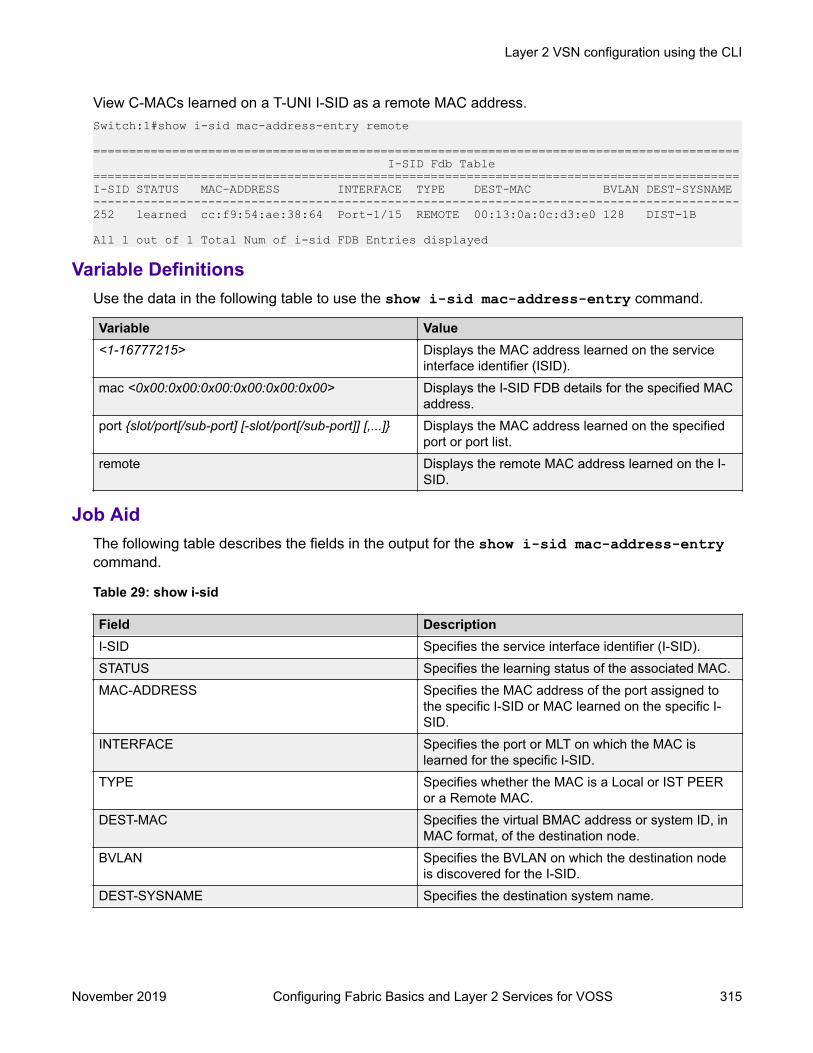
View C-MACs learned on a T-UNI I-SID as a remote MAC address.Switch:1#show i-sid mac-address-entry remote
========================================================================================== I-SID Fdb Table==========================================================================================I-SID STATUS MAC-ADDRESS INTERFACE TYPE DEST-MAC BVLAN DEST-SYSNAME------------------------------------------------------------------------------------------252 learned cc:f9:54:ae:38:64 Port-1/15 REMOTE 00:13:0a:0c:d3:e0 128 DIST-1B
All 1 out of 1 Total Num of i-sid FDB Entries displayed
Variable DefinitionsUse the data in the following table to use the show i-sid mac-address-entry command.
Variable Value<1-16777215> Displays the MAC address learned on the service
interface identifier (ISID).mac <0x00:0x00:0x00:0x00:0x00:0x00> Displays the I-SID FDB details for the specified MAC
address.port {slot/port[/sub-port] [-slot/port[/sub-port]] [,...]} Displays the MAC address learned on the specified
port or port list.remote Displays the remote MAC address learned on the I-
SID.
Job AidThe following table describes the fields in the output for the show i-sid mac-address-entrycommand.
Table 29: show i-sid
Field DescriptionI-SID Specifies the service interface identifier (I-SID).STATUS Specifies the learning status of the associated MAC.MAC-ADDRESS Specifies the MAC address of the port assigned to
the specific I-SID or MAC learned on the specific I-SID.
INTERFACE Specifies the port or MLT on which the MAC islearned for the specific I-SID.
TYPE Specifies whether the MAC is a Local or IST PEERor a Remote MAC.
DEST-MAC Specifies the virtual BMAC address or system ID, inMAC format, of the destination node.
BVLAN Specifies the BVLAN on which the destination nodeis discovered for the I-SID.
DEST-SYSNAME Specifies the destination system name.
Layer 2 VSN configuration using the CLI
November 2019 Configuring Fabric Basics and Layer 2 Services for VOSS 315

Viewing I-SID maximum MAC-limitPerform this procedure to view the maximum MAC learning limit information for an I-SID.
Important:
The command show i-sid limit-fdb-learning is supported only on the Virtual ServicesPlatform 4000 Series.
About this taskThe total MAC learning limit per switch is 32000. MAC learning on I-SID stops when the maximumlimit is reached.
ProcedureView the maximum MAC learning limit configured for an I-SID:
show i-sid limit-fdb-learning <1-16777215>ExampleView maximum MAC learning limit for all I-SIDs.Switch:1#show i-sid limit-fdb-learning
========================================= Isid MAC-Limit Info=========================================ISID MAC-LIMIT MAXMACID STATUS COUNT-----------------------------------------10 disabled 3200011 disabled 3200012 disabled 3200015 disabled 32000101 disabled 32000
All 5 out of 5 Total Num of i-sid Info displayed
View maximum MAC learning limit for a specific I-SID.Switch:1#show i-sid limit-fdb-learning 10
========================================= Isid MAC-Limit Info=========================================ISID MAC-LIMIT MAXMACID STATUS COUNT-----------------------------------------10 disabled 32000
All 1 out of 1 Total Num of i-sid Info displayed
Variable definitionsUse the data in the following table to use the show i-sid limit-fdb-learning command.
Layer 2 VSN configuration
November 2019 Configuring Fabric Basics and Layer 2 Services for VOSS 316

Important:
The command show i-sid limit-fdb-learning is supported only on the Virtual ServicesPlatform 4000 Series.
Variable Valuelimit-fdb-learning Displays the I-SID-based maximum MAC limit
information.<1–6777215> Displays the service interface identifier (ISID). The
ISID range is 1 to 16777215.
Job aidThe following table describes the fields in the output of the show i-sid limit-fdb-learningcommand.
Important:
The command show i-sid limit-fdb-learning is supported only on the Virtual ServicesPlatform 4000 Series.
Table 30: show i-sid limit-fdb-learning
Field DescriptionISID ID Specifies the service interface identifier (ISID)MAC-LIMIT STATUS Specifies whether the MAC learning limit is enabled
or disabledMAXMAC COUNT Specifies the MAC learning limit
Configuring an SPBM Layer 2 Switched UNI on an MLTShortest Path Bridging MAC (SPBM) supports Layer 2 Virtual Service Network (VSN) functionalitywhere Switched UNIs are bridged over the SPBM core infrastructure.
Switched User Network Interface (S-UNI) allows the association of local endpoints to I-SIDs basedon local port and VLAN together. With switched UNI, the same VLAN can be used on one port tocreate an endpoint to one I-SID, and on another port to create an endpoint to another I-SID.
Before you begin• You must configure the required SPBM and IS-IS infrastructure.
About this taskTo configure a Switched UNI on an MLT, you must create a Switched UNI I-SID, and map an MLT tothe Switched UNI I-SID.
Note:When you configure Switched UNI, Spanning tree is disabled on all the Switched UNI ports.
Layer 2 VSN configuration using the CLI
November 2019 Configuring Fabric Basics and Layer 2 Services for VOSS 317

Procedure1. Enter MLT Interface Configuration mode:
enableconfigure terminalinterface mlt <1-512>
2. Enable S-UNI on MLT:
flex-uni enable
Note:
You cannot enable Switched UNI on EAPoL enabled interface.
3. Configure a Switched UNI Service Instance Identifier (I-SID):
i-sid <1–16777215> [elan]This command automatically takes you to the Elan I-SID Configuration mode.
4. Add an MLT to a Switched UNI I-SID:
c-vid <c-vid> mlt <1–512>
Note:
You can run this command again to map a Switched UNI MLT to multiple I-SIDs.
5. Add untagged traffic to a Switched UNI I-SID:
untagged—traffic mlt <1–512> [bpdu enable]6. Display the Switched UNI information:
show mlt i-sidExampleSwitch> enableSwitch# configure terminalSwitch(config)# mlt 10Switch(config)# interface mlt 10Switch(config-mlt)# flex-uni enableSwitch(config-mlt)#i-sid 100Switch(elan:100)# c-vid 20 mlt 10Switch(elan:100)# untagged-traffic mlt 10 bpdu enableSwitch(elan:100)# show mlt i-sid================================================================================ MLT Isid Info
Layer 2 VSN configuration
November 2019 Configuring Fabric Basics and Layer 2 Services for VOSS 318

================================================================================ ISID ISID MLTID IFINDEX ID VLANID C-VID TYPE ORIGIN BPDU --------------------------------------------------------------------------------10 6153 100 N/A 20 ELAN CONFIG --------------------------------------------------------------------------------
1 out of 1 Total Num of i-sid endpoints displayed
Variable definitionsUse the data in the following table to use the i-sid command to configure a Switched UNI.
Variable Valuei-sid <1–16777215> elan Creates an Elan based service. The service interface identifier
(I-SID) range is 1 to 16777215.c-vid <c-vid> mlt <mlt-id> Specifies the customer VLAN ID. Different hardware platforms
support different customer VLAN ID ranges. Use the CLI Help tosee the available range for your switch.
untagged-traffic mlt <mlt-id> [bpduenable]
Add untagged traffic to the Elan-based service.
Configuring an SPBM Layer 2 Switched UNI on a PortShortest Path Bridging MAC (SPBM) supports Layer 2 Virtual Service Network (VSN) functionalitywhere Switched UNIs are bridged over the SPBM core infrastructure.
Before you begin• You must configure the required SPBM and IS-IS infrastructure.
About this taskTo configure a Switched UNI on a port, you must create a Switched UNI I-SID, and map the port tothe Switched UNI I-SID.
Note:When you configure Switched UNI, Spanning tree is disabled on all the Switched UNI ports.
Procedure1. Enter GigabitEthernet Interface Configuration mode:
enableconfigure terminalinterface GigabitEthernet {slot/port[/sub-port][-slot/port[/sub-port]][,...]}
Layer 2 VSN configuration using the CLI
November 2019 Configuring Fabric Basics and Layer 2 Services for VOSS 319

Note:
If your platform supports channelization and the port is channelized, you must alsospecify the sub-port in the format slot/port/sub-port.
2. Enable Switched UNI on a port:
flex-uni enable
Note:
You cannot enable Switched UNI on EAPoL enabled interface.
3. Configure a Switched UNI Service Instance Identifier (I-SID):
i-sid <1–16777215> [elan]This command automatically takes you to the Elan I-SID Configuration mode.
4. Add ports to a Switched UNI I-SID:
c-vid <c-vid> port {slot/port[/sub-port][-slot/port[/sub-port]][,...]}
5. Add untagged traffic to a Switched UNI I-SID:
untagged—traffic port {slot/port[/sub-port][-slot/port[/sub-port]][,...]} [bpdu enable]
6. Display the Switched UNI information:
show interface gigabitethernet i-sid {slot/port[/sub-port][-slot/port[/sub-port]][,...]}
ExampleSwitch> enableSwitch# configure terminalSwitch(config)# interface gigabitethernet 1/1,1/2Switch(config-if)# flex-uni enableSwitch(config-if)#i-sid 100Switch(elan:100)# c-vid 10 port 1/1,1/2Switch(elan:100)# untagged—traffic port 1/1,1/2 bpdu enableSwitch(elan:100)# show interface gigabitethernet i-sid================================================================================ PORT Isid Info================================================================================ ISID ISID PORTNUM IFINDEX ID VLANID C-VID TYPE ORIGIN BPDU --------------------------------------------------------------------------------1/1 192 100 N/A 10 ELAN CONFIG 1/2 193 100 N/A 10 ELAN CONFIG --------------------------------------------------------------------------------
Layer 2 VSN configuration
November 2019 Configuring Fabric Basics and Layer 2 Services for VOSS 320

2 out of 3 Total Num of i-sid endpoints displayed
Variable definitionsUse the data in the following table to use the i-sid command to configure a Switched UNI.
Variable Valuei-sid <1–16777215> elan Creates an Elan based service. The service interface identifier
(I-SID) range is 1 to 16777215.c-vid <c-vid> port {slot/port[/sub-port] [-slot/port[/sub-port]] [,...]}
Specifies the customer VLAN ID. Different hardware platformssupport different customer VLAN ID ranges. Use the CLI Help tosee the available range for your switch.
untagged-traffic < port {slot/port[/sub-port][-slot/port[/sub-port]] [,...]}> [bpdu enable]
Add untagged traffic to the Elan-based service.
Viewing all configured Switched UNI I-SIDsPerform this procedure to view all the configured Switched UNI I-SIDs including their types, ports,and MLTs.
Procedure1. Enter Privileged EXEC mode:
enable2. View all configured I-SIDs. This command displays CVLAN, T-UNI, and S-UNI based I-SIDs.
show i-sid3. View all S-UNI I-SIDs.
show i-sid [elan]4. View all associated MLT on the S-UNI I-SID.
show mlt i-sid [MLT ID <1–512>]5. View all associated ports on the S-UNI I-SID.
show interface gigabitethernet i-sid {slot/port[/sub-port][-slot/port[/sub-port]][,...]}
6. View all IS-IS SPBM multicast FIB entries.
show isis spbm multicast-fib detailExampleView all configured I-SIDs.Switch:1# show i-sid================================================================================== Isid Info
Layer 2 VSN configuration using the CLI
November 2019 Configuring Fabric Basics and Layer 2 Services for VOSS 321

==================================================================================ISID ISID PORT MLT ORIGINID TYPE VLANID INTERFACES INTERFACES ----------------------------------------------------------------------------------999 ELAN 99 - c110:100 CONFIG 99 1/21 -
c: customer vid u: untagged-traffic
All 1 out of 1 Total Num of i-sids displayed
View all S-UNI I-SIDs.Switch:1# show i-sid elan================================================================================== Isid Info==================================================================================ISID ISID PORT MLT ORIGINID TYPE VLANID INTERFACES INTERFACES ----------------------------------------------------------------------------------312 ELAN N/A - c710:1 DISC_BOTH 513 ELAN N/A - c513:1 DISC_BOTH 2000 ELAN 200 c20:1/3 - CONFIG 2001 ELAN 201 - c121:1 CONFIG 2002 ELAN 202 - c222:2 CONFIG 2004 ELAN 204 c420:1/3 - CONFIG - c421:1 - c422:2 3000 ELAN N/A c30:1/3 - CONFIG - c31:1 - c32:2 3010 ELAN N/A c130:1/3 - CONFIG 3020 ELAN N/A - - CONFIG 3030 ELAN N/A c330:1/3 - CONFIG 3040 ELAN N/A - c431:1 CONFIG - u:2
3050 ELAN N/A - c531:1 DISC_BOTH 3070 ELAN N/A c730:1/3 - CONFIG - c731:1 - c732:2 4000 ELAN 400 c40:1/3 - CONFIG - c41:1 - c42:2 4011 ELAN 411 c140:1/3 - CONFIG 4013 ELAN 413 c340:1/3 - CONFIG 4014 ELAN 414 - c441:1 CONFIG - c442:2 4015 ELAN 415 - c541:1 DISC_BOTH 4017 ELAN 417 c740:1/3 - CONFIG - c741:1 - c742:2 5010 ELAN 500 c50:1/3 - CONFIG - c51:1 - c52:2 5011 ELAN 501 u:1/3 - CONFIG 5013 ELAN 503 c350:1/3 - CONFIG 5014 ELAN 504 - c451:1 CONFIG - c452:2 5015 ELAN 505 - c551:1 CONFIG
- c552:2 5017 ELAN 507 c750:1/3 - CONFIG - c751:1
Layer 2 VSN configuration
November 2019 Configuring Fabric Basics and Layer 2 Services for VOSS 322
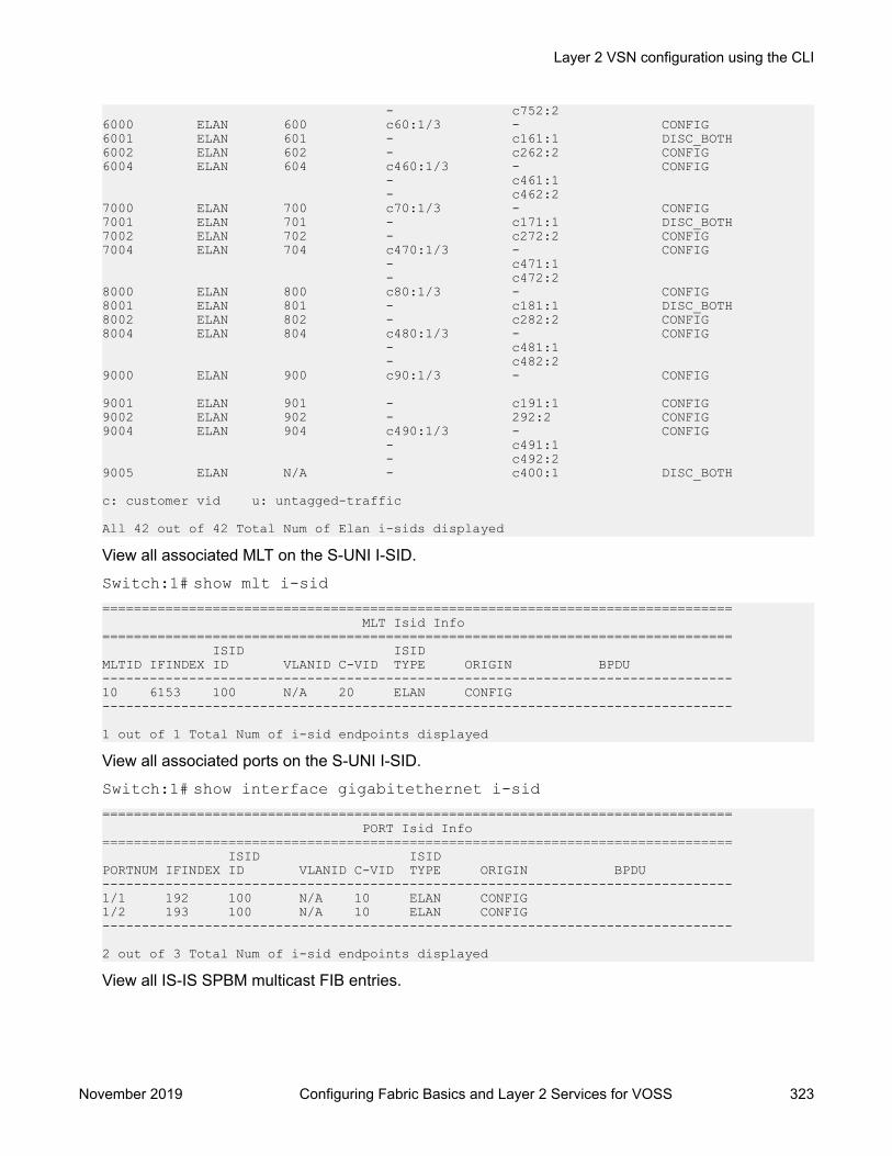
- c752:2 6000 ELAN 600 c60:1/3 - CONFIG 6001 ELAN 601 - c161:1 DISC_BOTH 6002 ELAN 602 - c262:2 CONFIG 6004 ELAN 604 c460:1/3 - CONFIG - c461:1 - c462:2 7000 ELAN 700 c70:1/3 - CONFIG 7001 ELAN 701 - c171:1 DISC_BOTH 7002 ELAN 702 - c272:2 CONFIG 7004 ELAN 704 c470:1/3 - CONFIG - c471:1 - c472:2 8000 ELAN 800 c80:1/3 - CONFIG 8001 ELAN 801 - c181:1 DISC_BOTH 8002 ELAN 802 - c282:2 CONFIG 8004 ELAN 804 c480:1/3 - CONFIG - c481:1 - c482:2 9000 ELAN 900 c90:1/3 - CONFIG
9001 ELAN 901 - c191:1 CONFIG 9002 ELAN 902 - 292:2 CONFIG 9004 ELAN 904 c490:1/3 - CONFIG - c491:1 - c492:2 9005 ELAN N/A - c400:1 DISC_BOTH
c: customer vid u: untagged-traffic
All 42 out of 42 Total Num of Elan i-sids displayed
View all associated MLT on the S-UNI I-SID.Switch:1# show mlt i-sid================================================================================ MLT Isid Info================================================================================ ISID ISID MLTID IFINDEX ID VLANID C-VID TYPE ORIGIN BPDU --------------------------------------------------------------------------------10 6153 100 N/A 20 ELAN CONFIG --------------------------------------------------------------------------------
1 out of 1 Total Num of i-sid endpoints displayed
View all associated ports on the S-UNI I-SID.Switch:1# show interface gigabitethernet i-sid================================================================================ PORT Isid Info================================================================================ ISID ISID PORTNUM IFINDEX ID VLANID C-VID TYPE ORIGIN BPDU --------------------------------------------------------------------------------1/1 192 100 N/A 10 ELAN CONFIG 1/2 193 100 N/A 10 ELAN CONFIG --------------------------------------------------------------------------------
2 out of 3 Total Num of i-sid endpoints displayed
View all IS-IS SPBM multicast FIB entries.
Layer 2 VSN configuration using the CLI
November 2019 Configuring Fabric Basics and Layer 2 Services for VOSS 323

Switch:1# show isis spbm multicast-fib detail============================================================================================== SPBM MULTICAST FIB ENTRY DETAIL INFO==============================================================================================MCAST DA ISID BVLAN SYSID HOST- OUTGOING- INCOMING CVLAN NAME INTERFACES INTERFACE----------------------------------------------------------------------------------------------03:77:77:00:0b:b8 3000 1001 0000.beb0.0007 BEB-07 MLT-1 1/2 0 c30:1/3 c31:MLT-1 c32:MLT-2 03:77:77:00:0f:a0 4000 1001 0000.beb0.0007 BEB-07 c40:1/3 1/2 400 c41:MLT-1 c42:MLT-2 03:77:77:00:13:92 5010 1001 0000.beb0.0007 BEB-07 c50:1/3 1/2 500 c51:MLT-1 c52:MLT-2 03:88:88:00:0b:b8 3000 1001 0000.beb0.0008 BEB-08 MLT-1 1/2 0 c30:1/3 c31:MLT-1 c32:MLT-2 03:88:88:00:0f:a0 4000 1001 0000.beb0.0008 BEB-08 c40:1/3 1/2 400 c41:MLT-1 -----------------------------------------------------------------------------------------------Total number of SPBM MULTICAST FIB entries 157------------------------------------------------------------------------------------------------
Variable definitionsUse the data in the following table to use the i-sid command.
Variable Valueelan Displays only all the Elan (S-UNI based) I-SIDs.MLT ID <1–512> Specifies the MLT associated with the Switched UNI I-SID.{slot/port[/sub-port][-slot/port[/sub-port]][,...]}
Specifies the ports associated with the Switched UNI I-SID.
Displaying C-VLAN and Switched UNI I-SID informationUse the following procedure to display C-VLAN and Switched UNI (S-UNI) I-SID information.
Procedure1. To enter User EXEC mode, log on to the switch.
2. Display the C-VLAN to I-SID associations:
show vlan i-sid <1-4059>3. Display I-SID information and Switched UNI to I-SID associations:
show i-sid <1–16777215>4. Display the IS-IS SPBM multicast-FIB calculation results by I-SID:
Layer 2 VSN configuration
November 2019 Configuring Fabric Basics and Layer 2 Services for VOSS 324

show isis spbm i-sid {all|config|discover} [vlan <1-4059>] [id <1–16777215>] [nick-name <x.xx.xx>]
5. Display all elan I-SID:
• show i-sid elan6. Display I-SID configured on MLT:
• show mlt i-sid7. Display I-SID configured on port:
• show interfaces gigabitethernet i-sidExampleSwitch:1>show vlan i-sid================================================================================ Vlan I-SID================================================================================VLAN_ID I-SID --------------------------------------------------------------------------------1 2 5 5 10 20 Switch:1>show isis spbm i-sid all================================================================================= SPBM ISID INFO=================================================================================ISID SOURCE NAME VLAN SYSID TYPE HOST_NAME---------------------------------------------------------------------------------200 1.11.16 1000 0014.c7e1.33df config Switch1 300 1.11.16 1000 0014.c7e1.33df config Switch1 400 1.11.16 1000 0014.c7e1.33df config Switch1 200 1.11.16 2000 0014.c7e1.33df config Switch1 300 1.11.16 2000 0014.c7e1.33df config Switch1 400 1.11.16 2000 0014.c7e1.33df config Switch1 200 1.12.45 1000 0016.ca23.73df discover Switch2 300 1.12.45 1000 0016.ca23.73df discover Switch2
--------------------------------------------------------------------------------- Total number of SPBM ISID entries configed: 6--------------------------------------------------------------------------------- Total number of SPBM ISID entries discovered: 2--------------------------------------------------------------------------------- Total number of SPBM ISID entries: 8---------------------------------------------------------------------------------Switch:1>show i-sid
================================================================================== Isid Info==================================================================================ISID ISID PORT MLT ORIGINID TYPE VLANID INTERFACES INTERFACES ----------------------------------------------------------------------------------999 ELAN 99 - c110:100 CONFIG 99 1/21 -
c: customer vid u: untagged-traffic
Layer 2 VSN configuration using the CLI
November 2019 Configuring Fabric Basics and Layer 2 Services for VOSS 325
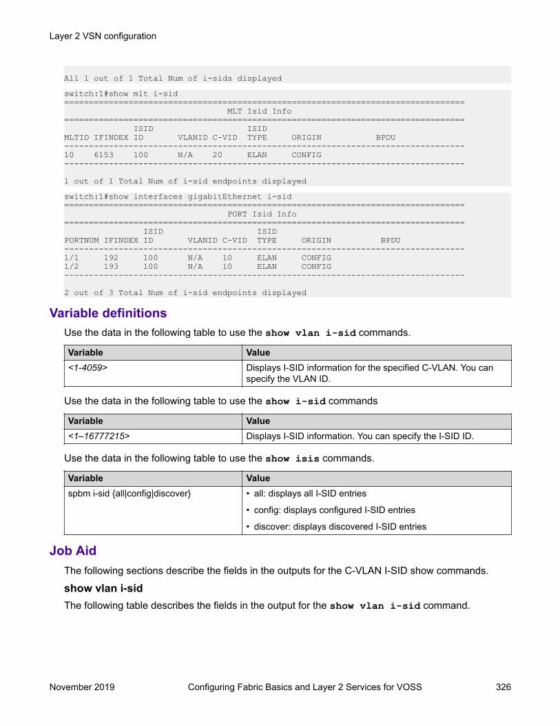
All 1 out of 1 Total Num of i-sids displayedswitch:1#show mlt i-sid ================================================================================= MLT Isid Info================================================================================= ISID ISID MLTID IFINDEX ID VLANID C-VID TYPE ORIGIN BPDU ---------------------------------------------------------------------------------10 6153 100 N/A 20 ELAN CONFIG ---------------------------------------------------------------------------------
1 out of 1 Total Num of i-sid endpoints displayedswitch:1#show interfaces gigabitEthernet i-sid ================================================================================= PORT Isid Info================================================================================= ISID ISID PORTNUM IFINDEX ID VLANID C-VID TYPE ORIGIN BPDU ---------------------------------------------------------------------------------1/1 192 100 N/A 10 ELAN CONFIG 1/2 193 100 N/A 10 ELAN CONFIG ---------------------------------------------------------------------------------
2 out of 3 Total Num of i-sid endpoints displayed
Variable definitionsUse the data in the following table to use the show vlan i-sid commands.
Variable Value<1-4059> Displays I-SID information for the specified C-VLAN. You can
specify the VLAN ID.
Use the data in the following table to use the show i-sid commands
Variable Value<1–16777215> Displays I-SID information. You can specify the I-SID ID.
Use the data in the following table to use the show isis commands.
Variable Valuespbm i-sid {all|config|discover} • all: displays all I-SID entries
• config: displays configured I-SID entries
• discover: displays discovered I-SID entries
Job AidThe following sections describe the fields in the outputs for the C-VLAN I-SID show commands.
show vlan i-sidThe following table describes the fields in the output for the show vlan i-sid command.
Layer 2 VSN configuration
November 2019 Configuring Fabric Basics and Layer 2 Services for VOSS 326

Parameter DescriptionVLAN_ID Indicates the VLAN IDs.I-SID Indicates the I-SIDs associated with the specified C-
VLANs.
show i-sidThe following table describes the fields in the output for the show i-sid command.
Parameter DescriptionI-SID Indicates the I-SID IDs.I-SID TYPE Indicated the I-SID type.
• T-UNI: Transparent Port UNI service.
• ELAN: any to any service (switched service).
• CVLAN: CVLAN based service.VLANID Indicates the VLAN IDs.PORT INTERFACES Indicated the port interface.MLT INTERFACES Indicates the MLT interface.ORIGIN Indicates if the I-SID is discovered by Fabric Attach
or manually added.
show isis spbm i-sidThe following describes the fields in the output for the show isis spbm i-sid command.
Parameter DescriptionISID {all | discover | config} Indicates the IS-IS SPBM I-SID identifier.
• all: display all SPBM I-SID
• discover: display discovered SPBM I-SID
• config: display configured SPBM I-SIDSOURCE NAME Indicates the nickname of the node where this I-SID
was configured or discovered.
Note:
SOURCE NAME is equivalent to nickname.VLAN Indicates the B-VLAN where this I-SID was
configured or discovered.SYSID Indicates the system identifier.TYPE Indicates the SPBM I-SID type as either configured
or discovered.HOST_NAME Indicates the host name of the multicast FIB entry.
Layer 2 VSN configuration using the CLI
November 2019 Configuring Fabric Basics and Layer 2 Services for VOSS 327

Layer 2 VSN configuration using EDMThis section provides procedures to configure Layer 2 Virtual Services Networks (VSNs) usingEnterprise Device Manager (EDM).
Configuring SPBM Layer 2 VSNAfter you have configured the SPBM infrastructure, you can enable the SPBM Layer 2 VirtualService Network (VSN) using the following procedure.
SPBM supports Layer 2 VSN functionality where customer VLANs (C-VLANs) are bridged over theSPBM core infrastructure.
At the BEBs, customer VLANs (C-VLAN) are mapped to I-SIDs based on the local serviceprovisioning. Outgoing frames are encapsulated in a MAC-in-MAC header, and then forwardedacross the core to the far-end BEB, which strips off the encapsulation and forwards the frame to thedestination network based on the I-SID-to-C-VLAN provisioning.
Before you begin• You must configure the required SPBM and IS-IS infrastructure, which includes the creation of
SPBM B-VLANs.• You must create the customer VLANs (C-VLANs) and add slots/ports.
Procedure1. In the navigation pane, expand the Configuration > VLAN folders.
2. Click VLANs.
3. Click the Advanced tab.
4. To map a C-VLAN to a Service instance identifier (I-SID), in the I-sid field, specify the I-SIDto associate with the specified VLAN.
5. Click Apply.
Important:• When a protocol VLAN is created, all ports are added to the VLAN including SPBM
ports. To configure a protocol-based VLAN as a C-VLAN, you must first remove theSPBM-enabled ports from the protocol based VLAN, and then configure the protocol-based VLAN as a C-VLAN.
• The switch reserves I-SID 0x00ffffff. The switch uses this I-SID to advertise the virtualB-MAC in a SMLT dual-homing environment. The platform clears the receive andtransmit bit of this I-SID, therefore I-SID 0x00ffffff cannot be used for any otherservice.
Layer 2 VSN configuration
November 2019 Configuring Fabric Basics and Layer 2 Services for VOSS 328

Displaying the remote MAC table for a C-VLANUse the following procedure to view a the remote MAC table for a C-VLAN.
Procedure1. In the navigation pane, expand the Configuration > VLAN folders.
2. Click VLANs.
3. Click the Remote MAC tab.
Remote MAC field descriptionsUse the data in the following table to use the Remote MAC tab.
Name DescriptionVlanId Indicates the VLAN ID for this MAC address.Addr Indicates the customer MAC address for which the bridge has
forwarding and/or filtering informationDestAddr Indicates the provider MAC address for which the bridge has
forwarding and/or filtering information.PrimaryBVlanId Indicates the primary B-VLAN ID for this MAC address.PrimaryDestSysName Indicates the primary system name of the node where the MAC
address entry comes from.PrimaryPort Either displays the value 0, or indicates the primary port on
which a frame came from.SecondaryBVlanId Indicates the secondary B-VLAN ID for this MAC addressSecondaryDestSysName Indicates the secondary system name of the node where the
MAC address entry comes from.SecondaryPort Either displays the value 0, or indicates the secondary port on
which a frame came from.SmltRemote Indicates the MAC address entry for the remote vIST peer.Status Indicates the status of this entry:
• other
• invalid
• learned
• self
• mgmt
Layer 2 VSN configuration using EDM
November 2019 Configuring Fabric Basics and Layer 2 Services for VOSS 329

Configuring UNIUse the following procedure to configure a Transparent Port UNI or Switched UNI by mapping an I-SID to a port or MLT and VLAN together.
Note:
If you are configuring a T-UNI to terminate on a port or MLT on a switch in a vIST switch cluster,you must also configure the T-UNI I-SID on the other switch of the vIST switch cluster. You mustconfigure the T-UNI I-SID on both switches of a vIST pair. It is not necessary to assign an actualport or MLT to the T-UNI on the second switch.
About this taskYou must first create a type of service instance identifier (I-SID) to create the different types ofservices available. After you create an I-SID you can add members (ports or MLTs) to the I-SID tocreate end-points for the service.
Procedure1. In the navigation pane, expand the Configuration > IS-IS folders.
2. Click ISID.
3. Click the Service tab.
4. To create a Transparent Port UNI service:
a. Click Insert.b. Select elan Transparent in the Type field.
c. Enter the I-SID in the Id field.
5. To create a Switched UNI service:
Note:
Flex UNI must be enabled to create a Switched UNI service.
a. Click Insert.b. Select elan in the Type field.
c. Enter the I-SID in the Id field.
6. Click Insert.
Service field descriptionsUse the data in the following table to use the Service tab.
Layer 2 VSN configuration
November 2019 Configuring Fabric Basics and Layer 2 Services for VOSS 330

Name DescriptionID Specifies a unique value to identify the service associated with
this entry.Type Specifies the type of service associated with this entry.MacLimitEnable Indicates whether the MAC limit is enabled (true) or disabled
(false).MaxMacLimit Indicates the maximum learned value of the MAC address for
each service I-SID.Action Specifies I-SID related actions.Origin Specifies the origin of the I-SID.
Associating a port and MLT with an ISID for Elan TransparentTransparent Port UNI (T-UNI) maps a port or MLT to an I-SID. Transparent Port UNI configures atransparent port where all traffic is MAC switched on an internal virtual port using the assigned I-SID. Multiple ports on the same unit and on other Backbone Edge Bridges (BEBs) are switched on acommon I-SID. No VLAN is involved in this process. The T-UNI port is not a member of any VLANor STG.
Use the following procedure to associate a port and MLT with an ISID.
Before you begin• You must configure Transparent Port UNI. For more information, see Configuring Transparent
UNI on page 330.• You must associate a T-UNI LACP MLT with a VLAN before mapping the LACP MLT to a T-UNI
ISID.
Caution:Ensure that a T-UNI LACP MLT is always associated with a VLAN (even if it is the defaultVLAN) before adding it to a T-UNI ISID. Otherwise, traffic is not forwarded on the T-UNILACP MLT.
Procedure1. In the navigation pane, expand the Configuration > IS-IS folders.
2. Click ISID.
3. Click on a row with type configured as elanTransparent.
4. Click ELAN.
5. Select port members.
6. Select MLT Ids.
7. Click Apply.
Layer 2 VSN configuration using EDM
November 2019 Configuring Fabric Basics and Layer 2 Services for VOSS 331
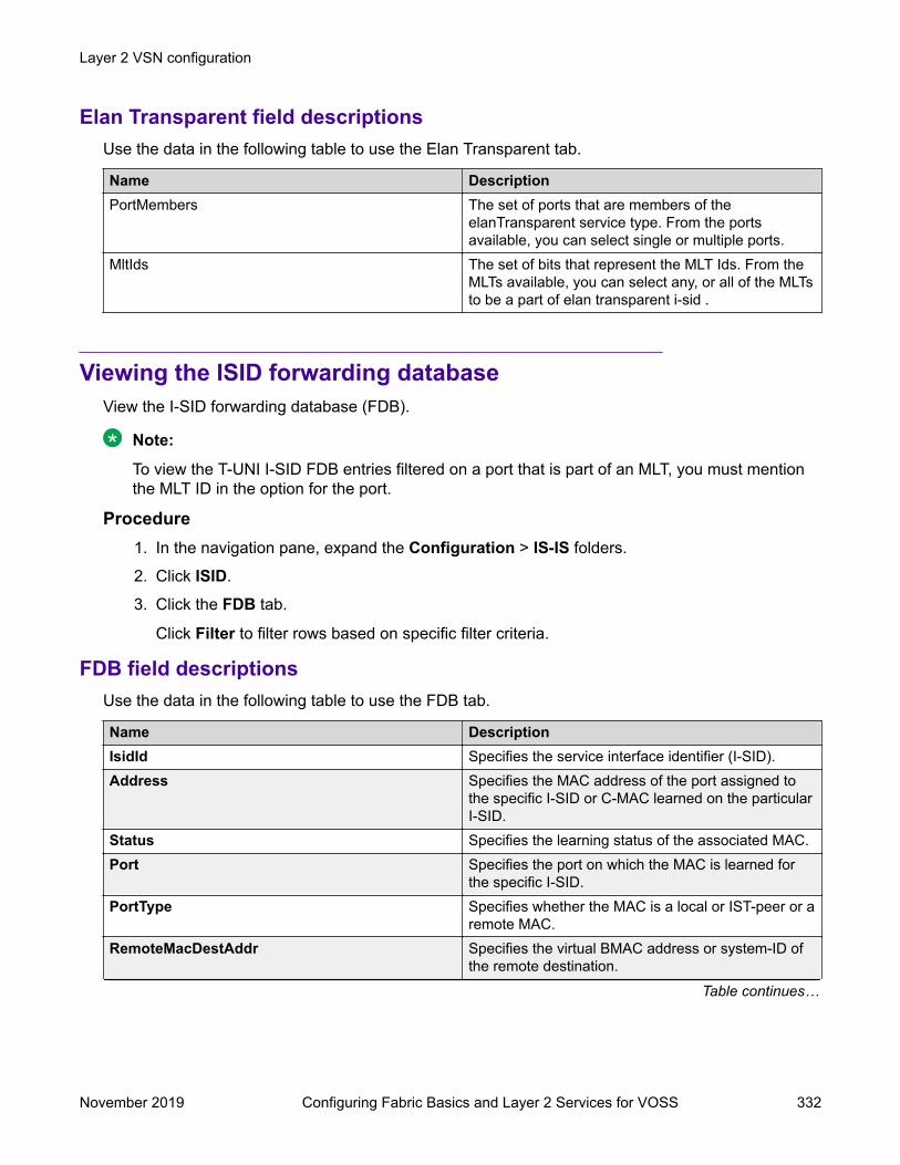
Elan Transparent field descriptionsUse the data in the following table to use the Elan Transparent tab.
Name DescriptionPortMembers The set of ports that are members of the
elanTransparent service type. From the portsavailable, you can select single or multiple ports.
MltIds The set of bits that represent the MLT Ids. From theMLTs available, you can select any, or all of the MLTsto be a part of elan transparent i-sid .
Viewing the ISID forwarding databaseView the I-SID forwarding database (FDB).
Note:
To view the T-UNI I-SID FDB entries filtered on a port that is part of an MLT, you must mentionthe MLT ID in the option for the port.
Procedure1. In the navigation pane, expand the Configuration > IS-IS folders.
2. Click ISID.
3. Click the FDB tab.
Click Filter to filter rows based on specific filter criteria.
FDB field descriptionsUse the data in the following table to use the FDB tab.
Name DescriptionIsidId Specifies the service interface identifier (I-SID).Address Specifies the MAC address of the port assigned to
the specific I-SID or C-MAC learned on the particularI-SID.
Status Specifies the learning status of the associated MAC.Port Specifies the port on which the MAC is learned for
the specific I-SID.PortType Specifies whether the MAC is a local or IST-peer or a
remote MAC.RemoteMacDestAddr Specifies the virtual BMAC address or system-ID of
the remote destination.Table continues…
Layer 2 VSN configuration
November 2019 Configuring Fabric Basics and Layer 2 Services for VOSS 332
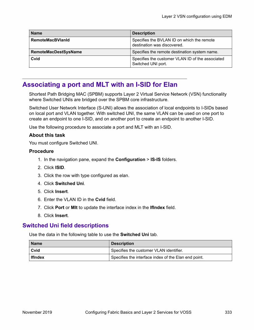
Name DescriptionRemoteMacBVlanId Specifies the BVLAN ID on which the remote
destination was discovered.RemoteMacDestSysName Specifies the remote destination system name.Cvid Specifies the customer VLAN ID of the associated
Switched UNI port.
Associating a port and MLT with an I-SID for ElanShortest Path Bridging MAC (SPBM) supports Layer 2 Virtual Service Network (VSN) functionalitywhere Switched UNIs are bridged over the SPBM core infrastructure.
Switched User Network Interface (S-UNI) allows the association of local endpoints to I-SIDs basedon local port and VLAN together. With switched UNI, the same VLAN can be used on one port tocreate an endpoint to one I-SID, and on another port to create an endpoint to another I-SID.
Use the following procedure to associate a port and MLT with an I-SID.
About this taskYou must configure Switched UNI.
Procedure1. In the navigation pane, expand the Configuration > IS-IS folders.
2. Click ISID.
3. Click the row with type configured as elan.
4. Click Switched Uni.5. Click Insert.6. Enter the VLAN ID in the Cvid field.
7. Click Port or Mlt to update the interface index in the IfIndex field.
8. Click Insert.
Switched Uni field descriptionsUse the data in the following table to use the Switched Uni tab.
Name DescriptionCvid Specifies the customer VLAN identifier.IfIndex Specifies the interface index of the Elan end point.
Layer 2 VSN configuration using EDM
November 2019 Configuring Fabric Basics and Layer 2 Services for VOSS 333

Viewing the I-SID interfaceView the I-SID interface.
Procedure1. In the navigation pane, expand the Configuration > IS-IS folders.
2. Click ISID.
3. Click the Interface tab.
Click Filter to filter rows on specific filter criteria.
Interface field descriptionsUse the data in the following table to use the Interface tab.
Name DescriptionIfIndex Specifies the interface index.Isid Specifies the service interface identifier (I-SID).Vlan Specifies the platform VLAN.Cvid Specifies the customer VID.Type Specifies the type of service associated with the I-SID interface.Origin Specifies the origin of the service associated with the I-SID
interface.Bpdu Specifies the BPDU forward option for the untagged traffic port.
Layer 2 VSN configuration examplesThis section provides configuration examples to configure Layer 2 VSNs.
Examples and network illustrations in this document may illustrate only one of the supportedplatforms. Unless otherwise noted, the concept illustrated applies to all supported platforms.
Layer 2 VSN configuration exampleThe following figure shows a sample Layer 2 VSN deployment.
Layer 2 VSN configuration
November 2019 Configuring Fabric Basics and Layer 2 Services for VOSS 334

Figure 46: Layer 2 VSN
The following sections show the steps required to configure the Layer 2 VSN parameters in thisexample. You must first configure basic SPBM and IS-IS infrastructure. For more information, see: SPBM configuration examples on page 251.
SwitchCVLAN CONFIGURATION
vlan create 10 type port-mstprstp 1vlan members 10 1/1 portmembervlan i-sid 10 12990010
SwitchDVLAN CONFIGURATION
vlan create 10 type port-mstprstp 1vlan members 10 1/1 portmembervlan i-sid 10 12990010
Verifying Layer 2 VSN operationThe following sections show how to verify the Layer 2 VSN operation in this example.
SwitchCSwitchC:1# show isis spbm i-sid all================================================================================ SPBM ISID INFO================================================================================ISID SOURCE NAME VLAN SYSID TYPE HOST_NAME--------------------------------------------------------------------------------12990010 f.30.14 4000 0014.0da0.13df discover SwitchD12990010 f.30.13 4000 0015.e89f.e3df config SwitchC
-------------------------------------------------------------------------------- Total number of SPBM ISID entries configured: 1-------------------------------------------------------------------------------- Total number of SPBM ISID entries discovered: 1-------------------------------------------------------------------------------- Total number of SPBM ISID entries: 2--------------------------------------------------------------------------------
SwitchC:1# show isis spbm multicast-fib================================================================================
Layer 2 VSN configuration examples
November 2019 Configuring Fabric Basics and Layer 2 Services for VOSS 335

SPBM MULTICAST FIB ENTRY INFO================================================================================MCAST DA ISID BVLAN SYSID HOST-NAME OUTGOING-INTERFACES--------------------------------------------------------------------------------f3:30:14:c6:36:3a 12990010 4000 0014.0da0.13df SwitchD 1/1f3:30:13:c6:36:3a 12990010 4000 0015.e89f.e3df SwitchC 1/30,1/1
SwitchDSwitchD:1# show isis spbm i-sid all================================================================================ SPBM ISID INFO================================================================================ISID SOURCE NAME VLAN SYSID TYPE HOST_NAME--------------------------------------------------------------------------------12990010 f.30.14 4000 0014.0da0.13df config SwitchD12990010 f.30.13 4000 0015.e89f.e3df discover SwitchC
SwitchD:1# show isis spbm multicast-fib================================================================================ SPBM MULTICAST FIB ENTRY INFO================================================================================MCAST DA ISID BVLAN SYSID HOST-NAME OUTGOING-INTERFACES--------------------------------------------------------------------------------f3:30:14:c6:36:3a 12990010 4000 0014.0da0.13df SwitchD MLT-1,1/1f3:30:13:c6:36:3a 12990010 4000 0015.e89f.e3df SwitchC 1/1
SwitchC — verifying with CFMSwitchC:1# l2 tracetree 4000 12990010
Please wait for l2tracetree to complete or press any key to abort
l2tracetree to f3:30:13:c6:36:3a, vlan 4000 i-sid 12990010 nickname f.30.13 hops 641 SwitchC 00:15:e8:9f:e3:df -> SwitchG 00:0e:62:25:a3:df2 SwitchG 00:0e:62:25:a3:df -> SwitchD 00:14:0d:a0:13:df
SwitchD — verifying with CFMSwitchD:1# l2 tracetree 4000 12990010
Please wait for l2tracetree to complete or press any key to abort
l2tracetree to f3:30:14:c6:36:3a, vlan 4000 i-sid 12990010 nickname f.30.14 hops 641 SwitchD 00:14:0d:a0:13:df -> SwitchG 00:0e:62:25:a3:df2 SwitchG 00:0e:62:25:a3:df -> SwitchC 00:15:e8:9f:e3:df
SwitchC — verifying FDBSwitchC:1# show vlan mac-address-entry 10================================================================================ Vlan Fdb================================================================================VLAN MACID STATUS ADDRESS INTERFACE TUNNEL--------------------------------------------------------------------------------10 learned 00:00:00:00:00:01 Port-1/1 SwitchD10 learned 00:00:00:00:00:02 Port-1/1 SwitchD
2 out of 4 entries in all fdb(s) displayed.
SwitchC:1# show vlan remote-mac-table 10================================================================================ Vlan Remote Mac Table================================================================================VLAN STATUS MAC-ADDRESS DEST-MAC BVLAN DEST-SYSNAME PORTS
Layer 2 VSN configuration
November 2019 Configuring Fabric Basics and Layer 2 Services for VOSS 336

--------------------------------------------------------------------------------10 learned 00:00:00:00:00:02 00:14:0d:a0:13:df 0014.0da0.13df SwitchD 1/30-------------------------------------------------------------------------------- Total number of VLAN Remote MAC entries 1 --------------------------------------------------------------------------------
SwitchD — verifying FDBSwitchD:1# show vlan mac-address-entry 10================================================================================ Vlan Fdb================================================================================VLAN MACID STATUS ADDRESS INTERFACE TUNNEL--------------------------------------------------------------------------------10 learned 00:00:00:00:00:01 Port-1/1 SwitchC10 learned 00:00:00:00:00:02 Port-1/1 SwitchC
2 out of 4 entries in all fdb(s) displayed.
SwitchD:1# show vlan remote-mac-table 10================================================================================ Vlan Remote Mac Table================================================================================VLAN STATUS MAC-ADDRESS DEST-MAC DEST-SYSID DEST-SYSNAME PORTS--------------------------------------------------------------------------------10 learned 00:00:00:00:00:01 00:15:e8:9f:e3:df 0015.e89f.e3df SwitchC MLT-1-------------------------------------------------------------------------------- Total number of VLAN Remote MAC entries 1 --------------------------------------------------------------------------------
Layer 2 VSN example with VLAN ID translationThe following figure shows a sample Layer 2 VSN deployment where the C- VLAN IDs are differentat each end. You must first configure basic SPBM and IS-IS infrastructure. For more information,see SPBM configuration examples on page 251.
Figure 47: Layer 2 VSN with different VLAN IDs
The following sections show the steps required to configure the Layer 2 VSN parameters in thisexample.
SwitchCVLAN CONFIGURATION
Layer 2 VSN configuration examples
November 2019 Configuring Fabric Basics and Layer 2 Services for VOSS 337

vlan create 9 type port 1vlan members 9 1/1 portmembervlan i-sid 9 9
SwitchDVLAN CONFIGURATION
vlan create 19 type port 1vlan members 19 1/1 portmembervlan i-sid 19 9
Layer 2 VSN configuration
November 2019 Configuring Fabric Basics and Layer 2 Services for VOSS 338

Chapter 6: Inter-VSN Routing Configuration
Table 31: Inter-VSN Routing product support
Feature Product Release introducedInter-VSN routing (IPv4) VSP 4450 Series VSP 4000 4.0
VSP 4900 Series VOSS 8.1VSP 7200 Series VOSS 4.2.1VSP 7400 Series VOSS 8.0VSP 8200 Series VSP 8200 4.0VSP 8400 Series VOSS 4.2VSP 8600 Series VSP 8600 6.1XA1400 Series VOSS 8.0.50
Inter-VSN routing (IPv6) VSP 4450 Series VOSS 4.1VSP 4900 Series VOSS 8.1VSP 7200 Series VOSS 4.2.1VSP 7400 Series VOSS 8.0VSP 8200 Series VOSS 4.1VSP 8400 Series VOSS 4.2VSP 8600 Series Not SupportedXA1400 Series Not Supported
This section provides concepts and procedures to configure Inter-Virtual Services Network (VSN)routing.
Inter-VSN routing configuration fundamentalsThis section provides fundamental concepts on Inter-VSN Routing.
Inter-VSN routingInter-VSN routing with SPBM allows routing between Layer 2 VLANs with different I-SIDs.
November 2019 Configuring Fabric Basics and Layer 2 Services for VOSS 339

Figure 48: Inter-VSN routing
Inter-VSN routing provides a routing hub for Layer 2 Virtual Services Network edge devices, Layer 3devices, routers, or hosts connected to the SPBM cloud using the SPBM Layer 2 VSN service. Togo between a routed network, a Layer 2 VSN termination point provides the routing services to hoponto another Layer 2 VSN, using I-SID.
Note:The Layer 2 VLANs must be in the same VRF. You cannot route traffic between two differentVRFs with Inter-VSN routing.
In this example, the C-VLANs are associated with I-SIDs on the BEBs using SPBM Layer 2 VSN.With Inter-VSN routing enabled, BCB C can route traffic between VLAN 11 (I-SID 2011) and VLAN12 (I-SID 2012).IP interfaces are where the routing instance exists. In this case, on Switch-20.
Note:The switch does not support IP multicast over Fabric Connect routing on inter-VSN routinginterfaces.
Inter-VSN routing configuration using the CLIThis section provides a procedure to configure Inter-VSN routing using the CLI.
Configuring SPBM Inter-VSN RoutingInter-VSN allows you to route between IP networks on Layer 2 VLANs with different I-SIDs. Inter-VSN routing is typically used only when you have to extend a VLAN as a Layer 2 Virtual ServicesNetwork (VSN) for applications such as vMotion. Normally, it is recommended to use IP Shortcuts orLayer 3 VSNs to route traffic. You must configure both the Backbone Edge Bridges (BEBs) and theBackbone Core Bridge (BCB).
Inter-VSN Routing Configuration
November 2019 Configuring Fabric Basics and Layer 2 Services for VOSS 340
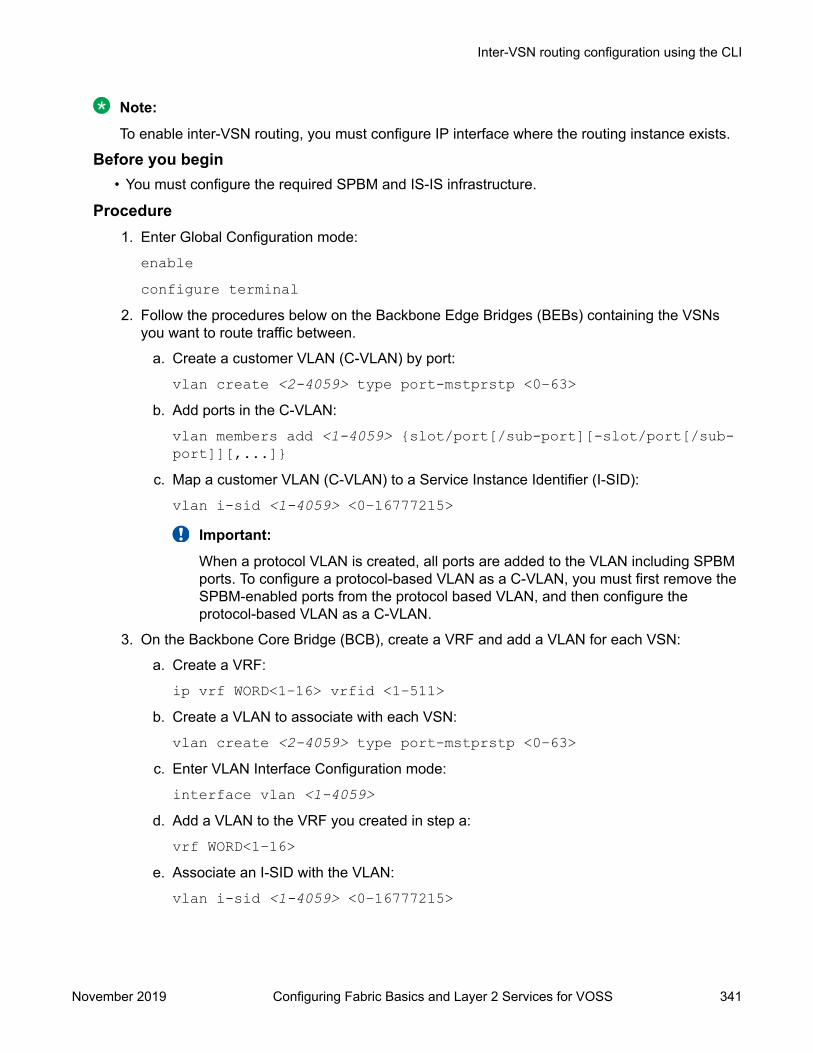
Note:
To enable inter-VSN routing, you must configure IP interface where the routing instance exists.
Before you begin• You must configure the required SPBM and IS-IS infrastructure.
Procedure1. Enter Global Configuration mode:
enableconfigure terminal
2. Follow the procedures below on the Backbone Edge Bridges (BEBs) containing the VSNsyou want to route traffic between.
a. Create a customer VLAN (C-VLAN) by port:
vlan create <2-4059> type port-mstprstp <0–63>b. Add ports in the C-VLAN:
vlan members add <1-4059> {slot/port[/sub-port][-slot/port[/sub-port]][,...]}
c. Map a customer VLAN (C-VLAN) to a Service Instance Identifier (I-SID):
vlan i-sid <1-4059> <0–16777215>Important:
When a protocol VLAN is created, all ports are added to the VLAN including SPBMports. To configure a protocol-based VLAN as a C-VLAN, you must first remove theSPBM-enabled ports from the protocol based VLAN, and then configure theprotocol-based VLAN as a C-VLAN.
3. On the Backbone Core Bridge (BCB), create a VRF and add a VLAN for each VSN:
a. Create a VRF:
ip vrf WORD<1–16> vrfid <1–511>b. Create a VLAN to associate with each VSN:
vlan create <2-4059> type port-mstprstp <0–63>c. Enter VLAN Interface Configuration mode:
interface vlan <1-4059>d. Add a VLAN to the VRF you created in step a:
vrf WORD<1–16>e. Associate an I-SID with the VLAN:
vlan i-sid <1-4059> <0–16777215>
Inter-VSN routing configuration using the CLI
November 2019 Configuring Fabric Basics and Layer 2 Services for VOSS 341

Important:
When a protocol VLAN is created, all ports are added to the VLAN including SPBMports. To configure a protocol-based VLAN as a C-VLAN, you must first remove theSPBM-enabled ports from the protocol based VLAN, and then configure theprotocol-based VLAN as a C-VLAN.
The switch reserves I-SID 0x00ffffff. The switch uses this I-SID to advertise thevirtual B-MAC in a SMLT dual-homing environment. The platform clears the receiveand transmit bit of this I-SID, therefore I-SID 0x00ffffff cannot be used for any otherservice.
f. Configure an IP address for the VLAN:
ip address {A.B.C.D/X}g. Repeat steps b to f for every VLAN you want to route traffic between.
Variable definitionsUse the data in the following table to use the vlan create command.
Variable Value<2-4059> Specifies the VLAN ID in the range of 2 to 4059. VLAN ID 1 is
the default VLAN and you cannot create or delete VLAN ID 1. Bydefault, the system reserves VLAN IDs 4060 to 4094 for internaluse. On switches that support the vrf-scaling and spbm-config-mode boot configuration flags, if you enable these flags, thesystem also reserves VLAN IDs 3500 to 3998.
type port-mstprstp <0–63> [color <0–32> ]
Creates a VLAN by port:
• <0–63> is the STP instance ID.
• color <0–32> is the color of the VLAN.
Use the data in the following table to use the vlan members add command.
Variable Value<1-4059> Specifies the VLAN ID in the range of 1 to 4059. By
default, VLAN IDs 1 to 4059 are configurable and thesystem reserves VLAN IDs 4060 to 4094 for internaluse. On switches that support the vrf-scaling andspbm-config-mode boot configuration flags, if youenable these flags, the system also reserves VLANIDs 3500 to 3998. VLAN ID 1 is the default VLANand you cannot create or delete VLAN ID 1.
{slot/port[/sub-port] [-slot/port[/sub-port]] [,...]} Identifies the slot and port in one of the followingformats: a single slot and port (slot/port), a range ofslots and ports (slot/port-slot/port), or a series ofslots and ports (slot/port,slot/port,slot/port). If yourplatform supports channelization and the port is
Table continues…
Inter-VSN Routing Configuration
November 2019 Configuring Fabric Basics and Layer 2 Services for VOSS 342

Variable Valuechannelized, you must also specify the sub-port inthe format slot/port/sub-port.
Use the data in the following table to use the vlan i-sid command.
Variable Valuevlan i-sid <1-4059> <0–16777215> Specifies the customer VLAN (C-VLAN) to associate with the I-
SID.
Use the no or default options to remove the I-SID from thespecified VLAN.
Use the data in the following table to use the ip vrf command.
Variable ValueWORD <1–16> Create the VRF and specify the name of the VRF
instance.vrfid <1–511> Specifies the VRF instance by number.
Use the data in the following table to use the vrf command.
Variable ValueWORD <1–16> Specifies the VRF name. Associates a port to a VRF.
Use the data in the following table to use the ip address command.
Variable Value{A.B.C.D/X} Configure an IP address for the VLAN.
Inter-VSN routing configuration using EDMThis section provides procedures to configure Inter-VSN routing using Enterprise Device Manager(EDM).
Configuring BEBs for Inter-VSN routingInter-VSN allows you to route between IP networks on Layer 2 VLANs with different I-SIDs. Inter-VSN routing is typically used only when you have to extend a VLAN as a Layer 2 Virtual ServicesNetwork (VSN) for applications such as vMotion. Use IP Shortcuts or Layer 3 VSNs to route traffic.You must configure both the Backbone Edge Bridges (BEBs) and the Backbone Core Bridge (BCB).
Inter-VSN routing configuration using EDM
November 2019 Configuring Fabric Basics and Layer 2 Services for VOSS 343
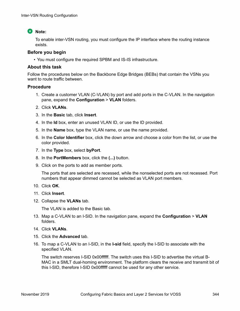
Note:
To enable inter-VSN routing, you must configure the IP interface where the routing instanceexists.
Before you begin• You must configure the required SPBM and IS-IS infrastructure.
About this taskFollow the procedures below on the Backbone Edge Bridges (BEBs) that contain the VSNs youwant to route traffic between.
Procedure1. Create a customer VLAN (C-VLAN) by port and add ports in the C-VLAN. In the navigation
pane, expand the Configuration > VLAN folders.
2. Click VLANs.
3. In the Basic tab, click Insert.4. In the Id box, enter an unused VLAN ID, or use the ID provided.
5. In the Name box, type the VLAN name, or use the name provided.
6. In the Color Identifier box, click the down arrow and choose a color from the list, or use thecolor provided.
7. In the Type box, select byPort.8. In the PortMembers box, click the (...) button.
9. Click on the ports to add as member ports.
The ports that are selected are recessed, while the nonselected ports are not recessed. Portnumbers that appear dimmed cannot be selected as VLAN port members.
10. Click OK.
11. Click Insert.12. Collapse the VLANs tab.
The VLAN is added to the Basic tab.
13. Map a C-VLAN to an I-SID. In the navigation pane, expand the Configuration > VLANfolders.
14. Click VLANs.
15. Click the Advanced tab.
16. To map a C-VLAN to an I-SID, in the I-sid field, specify the I-SID to associate with thespecified VLAN.
The switch reserves I-SID 0x00ffffff. The switch uses this I-SID to advertise the virtual B-MAC in a SMLT dual-homing environment. The platform clears the receive and transmit bit ofthis I-SID, therefore I-SID 0x00ffffff cannot be used for any other service.
Inter-VSN Routing Configuration
November 2019 Configuring Fabric Basics and Layer 2 Services for VOSS 344

17. Click Apply.
Important:
When a protocol VLAN is created, all ports are added to the VLAN including SPBMports. To configure a protocol-based VLAN as a C-VLAN, you must first remove theSPBM-enabled ports from the protocol based VLAN, and then configure the protocol-based VLAN as a C-VLAN.
18. Configure the Backbone Core Bridge (BCB) for Inter-VSN Routing. For more information,see Configuring BCBs for Inter-VSN routing on page 348.
Advanced field descriptionsUse the data in the following table to use the Advanced tab.
Name DescriptionId Specifies the VLAN ID in the range of 1 to 4059. By
default, VLAN IDs 1 to 4059 are configurable and thesystem reserves VLAN IDs 4060 to 4094 for internaluse. On switches that support the vrf-scaling andspbm-config-mode boot configuration flags, if youenable these flags, the system also reserves VLANIDs 3500 to 3998. VLAN ID 1 is the default VLANand you cannot create or delete VLAN ID 1.
Name Specifies the name of the VLAN.IfIndex Specifies the logical interface index assigned to the
VLAN.Type Specifies the type of VLAN:
• byPort
• byProtocolId
• spbm-bvlan
• privateI-sid Specifies the I-SID number assigned to a customer
VLAN (C-VLAN). The range is 0 – 16777215. Thedefault value is 0, which indicates that no I-SID isassigned.
ProtocolId Specifies the network protocol for protocol-basedVLANs.
If the VLAN type is not protocol-based, None isdisplayed in the Basic tab ProtocolId field.
AgingTime Specifies the timeout period for dynamic VLANmembership. A potential VLAN port is made ACTIVEafter it receives a packet that matches the VLAN; if
Table continues…
Inter-VSN routing configuration using EDM
November 2019 Configuring Fabric Basics and Layer 2 Services for VOSS 345

Name Descriptionno such packet is received for AgingTime seconds,the port is no longer active. The default is 600.
MacAddress Specifies the MAC address assigned to the virtualrouter interface for this VLAN. This field is relevantonly after the VLAN is configured for routing. ThisMAC address is used as the Source MAC in routedframes and ARP replies.
Vlan Operation Action Performs an operation on the VLAN. The values are:
• none
• flushMacFdb: Configures action to flushMacFdb.This action removes the learned MAC addressesfrom the forwarding database for the selectedVLAN.
• flushArp: Configures action to flushArp. This actionremoves the ARP entries from the address tablefor the selected VLAN.
• flushIp: Configures action to flushIp. This actionremoves the learned IP addresses from theforwarding table for the selected VLAN.
• flushDynMemb: Configures action toflushDynMemb. This action removes port membersnot configured as static from the list of active portmembers of a policy-based VLAN and removesMAC addresses learned on those ports.
• all: Configures action to all. This action performs allthe supported actions; it does not perform theSnoop-related actions.
The default is none.Result Specifies the result code after you perform an action.NlbMode Enables or disables Microsoft Network Load
Balancing (NLB) operations on the VLAN. Thedefault is disabled.
SpbMulticast Enables or disables Multicast over Fabric Connect.The default is disabled.
SpbPimGatewayMulticast Enables or disables SPB-PIM Gateway Multicast ona VLAN. The default is disabled.
RmonEnable Enables or disables Remote Monitoring (RMON) onthe interface. The default is disabled.
Ipv6FhsSnoopDhcpEnable Enables or disables IPv6 dhcp snooping on a VLAN.The default is disabled.
Table continues…
Inter-VSN Routing Configuration
November 2019 Configuring Fabric Basics and Layer 2 Services for VOSS 346

Name DescriptionIpv6FhsNDInspectionEnable Enables or disables neighbor discovery (ND)
inspection on a VLAN. The default is disabled.DvrEnable Enables or disables DvR on a VLAN that is
configured on the DvR Controller. The default isdisabled.
Note:
You must enable DvR on every VLAN that isconfigured on a DvR Controller.
DvrGwIpv4Addr Specifies the DvR gateway IPv4 address for a VLAN.
Important:
Ensure that you configure the same gatewayIPv4 address on all Controllers in the DvRdomain that belong to a VLAN.
Basic Field DescriptionsUse the data in the following table to use the Basic tab.
Name DescriptionId Specifies the VLAN ID in the range of 2 to 4059. VLAN ID 1 is the default VLAN
and you cannot create or delete VLAN ID 1. By default, the system reserves VLANIDs 4060 to 4094 for internal use. On switches that support the vrf-scaling andspbm-config-mode boot configuration flags, if you enable these flags, the systemalso reserves VLAN IDs 3500 to 3998.
Name Specifies the name of the VLAN.IfIndex Specifies the logical interface index assigned to the VLAN.Color Identifier Specifies a proprietary color scheme to associate a color with the VLAN. Color
does not affect how frames are forwarded.Type Specifies the type of VLAN:
• byPort
• byProtocolId
• spbm-bvlan
• privateMstpInstance Identifies the MSTP instance.VrfId Indicates the Virtual Router to which the VLAN belongs.VrfName Indicates the name of the Virtual Router to which the VLAN belongs.PortMembers Specifies the slot/port of each VLAN member. The sub-port only appears for
channelized ports.
Table continues…
Inter-VSN routing configuration using EDM
November 2019 Configuring Fabric Basics and Layer 2 Services for VOSS 347
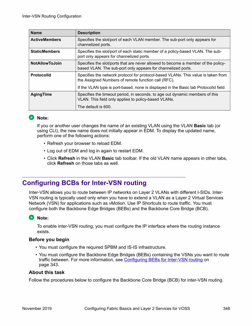
Name DescriptionActiveMembers Specifies the slot/port of each VLAN member. The sub-port only appears for
channelized ports.StaticMembers Specifies the slot/port of each static member of a policy-based VLAN. The sub-
port only appears for channelized ports.NotAllowToJoin Specifies the slot/ports that are never allowed to become a member of the policy-
based VLAN. The sub-port only appears for channelized ports.ProtocolId Specifies the network protocol for protocol-based VLANs. This value is taken from
the Assigned Numbers of remote function call (RFC).
If the VLAN type is port-based, none is displayed in the Basic tab ProtocolId field.AgingTime Specifies the timeout period, in seconds, to age out dynamic members of this
VLAN. This field only applies to policy-based VLANs.
The default is 600.
Note:If you or another user changes the name of an existing VLAN using the VLAN Basic tab (orusing CLI), the new name does not initially appear in EDM. To display the updated name,perform one of the following actions:
• Refresh your browser to reload EDM.• Log out of EDM and log in again to restart EDM.• Click Refresh in the VLAN Basic tab toolbar. If the old VLAN name appears in other tabs,
click Refresh on those tabs as well.
Configuring BCBs for Inter-VSN routingInter-VSN allows you to route between IP networks on Layer 2 VLANs with different I-SIDs. Inter-VSN routing is typically used only when you have to extend a VLAN as a Layer 2 Virtual ServicesNetwork (VSN) for applications such as vMotion. Use IP Shortcuts to route traffic. You mustconfigure both the Backbone Edge Bridges (BEBs) and the Backbone Core Bridge (BCB).
Note:
To enable inter-VSN routing, you must configure the IP interface where the routing instanceexists.
Before you begin• You must configure the required SPBM and IS-IS infrastructure.• You must configure the Backbone Edge Bridges (BEBs) containing the VSNs you want to route
traffic between. For more information, see Configuring BEBs for Inter-VSN routing onpage 343.
About this taskFollow the procedures below to configure the Backbone Core Bridge (BCB) for inter-VSN routing.
Inter-VSN Routing Configuration
November 2019 Configuring Fabric Basics and Layer 2 Services for VOSS 348

Procedure1. On the Backbone Core Bridge (BCB), create a VRF. In the navigation pane, expand the
Configuration > IP folders.
2. Click VRF.
3. Click Insert.4. Specify the VRF ID.
5. Name the VRF instance.
6. Configure the other parameters as required.
7. Click Insert.8. Create a VLAN to associate with each VSN. In the navigation pane, expand the
Configuration > VLAN folders.
9. Click VLANs.
10. In the Basic tab, click Insert.11. In the Id box, enter an unused VLAN ID, or use the ID provided.
12. In the Name box, type the VLAN name, or use the name provided.
13. In the Color Identifier box, click the down arrow and choose a color from the list, or use thecolor provided.
14. In the Type box, select byPort.15. In the PortMembers box, click the (...) button.
16. Click on the ports to add as member ports.
The ports that are selected are recessed, while the nonselected ports are not recessed. Portnumbers that appear dimmed cannot be selected as VLAN port members.
17. Click OK.
18. Click Insert.19. Collapse the VLANs tab.
The VLAN is added to the Basic tab.
20. Associate the VLAN with an I-SID. In the navigation pane, expand the Configuration >VLAN folders.
21. Click VLANs.
22. In the VLANs tab, click the Advanced tab.
23. In the I-sid box, specify the I-SID to associate with the VLAN.
24. Click Apply.
25. Configure a circuitless IP interface (CLIP). In the navigation pane, expand theConfiguration > IP folders.
Inter-VSN routing configuration using EDM
November 2019 Configuring Fabric Basics and Layer 2 Services for VOSS 349

26. Click IP.
27. Click the Circuitless IP tab.
28. Click Insert.29. In the Interface field, assign a CLIP interface number.
30. Enter the IP address.
31. Enter the network mask.
32. Click Insert.
VRF field descriptionsUse the data in the following table to help you use the VRF tab.
Name DescriptionId Specifies the ID number of the VRF instance. VRF ID 0 is reserved for
the GlobalRouter.Name Names the VRF instance.ContextName Identifies the VRF. The SNMPv2 Community String or SNMPv3
contextName denotes the VRF context and is used to logicallyseparate the MIB module management.
TrapEnable Enables the VRF to send VRF Lite-related traps (VrfUp and VrfDown).The default is true.
MaxRoutes Configures the maximum number of routes allowed for the VRF. Themaximum value varies per platform. See Release Notes for VOSS forplatform-specific scaling information.
The default value is 10000.MaxRoutesTrapEnable Enables the generation of the VRF Max Routes Exceeded traps. The
default is true.
Advanced field descriptionsUse the data in the following table to use the Advanced tab.
Name DescriptionId Specifies the VLAN ID in the range of 1 to 4059. By
default, VLAN IDs 1 to 4059 are configurable and thesystem reserves VLAN IDs 4060 to 4094 for internaluse. On switches that support the vrf-scaling andspbm-config-mode boot configuration flags, if youenable these flags, the system also reserves VLANIDs 3500 to 3998. VLAN ID 1 is the default VLANand you cannot create or delete VLAN ID 1.
Name Specifies the name of the VLAN.
Table continues…
Inter-VSN Routing Configuration
November 2019 Configuring Fabric Basics and Layer 2 Services for VOSS 350

Name DescriptionIfIndex Specifies the logical interface index assigned to the
VLAN.Type Specifies the type of VLAN:
• byPort
• byProtocolId
• spbm-bvlan
• privateI-sid Specifies the I-SID number assigned to a customer
VLAN (C-VLAN). The range is 0 – 16777215. Thedefault value is 0, which indicates that no I-SID isassigned.
ProtocolId Specifies the network protocol for protocol-basedVLANs.
If the VLAN type is not protocol-based, None isdisplayed in the Basic tab ProtocolId field.
AgingTime Specifies the timeout period for dynamic VLANmembership. A potential VLAN port is made ACTIVEafter it receives a packet that matches the VLAN; ifno such packet is received for AgingTime seconds,the port is no longer active. The default is 600.
MacAddress Specifies the MAC address assigned to the virtualrouter interface for this VLAN. This field is relevantonly after the VLAN is configured for routing. ThisMAC address is used as the Source MAC in routedframes and ARP replies.
Vlan Operation Action Performs an operation on the VLAN. The values are:
• none
• flushMacFdb: Configures action to flushMacFdb.This action removes the learned MAC addressesfrom the forwarding database for the selectedVLAN.
• flushArp: Configures action to flushArp. This actionremoves the ARP entries from the address tablefor the selected VLAN.
• flushIp: Configures action to flushIp. This actionremoves the learned IP addresses from theforwarding table for the selected VLAN.
• flushDynMemb: Configures action toflushDynMemb. This action removes port membersnot configured as static from the list of active portmembers of a policy-based VLAN and removesMAC addresses learned on those ports.
Table continues…
Inter-VSN routing configuration using EDM
November 2019 Configuring Fabric Basics and Layer 2 Services for VOSS 351

Name Description• all: Configures action to all. This action performs all
the supported actions; it does not perform theSnoop-related actions.
The default is none.Result Specifies the result code after you perform an action.NlbMode Enables or disables Microsoft Network Load
Balancing (NLB) operations on the VLAN. Thedefault is disabled.
SpbMulticast Enables or disables Multicast over Fabric Connect.The default is disabled.
SpbPimGatewayMulticast Enables or disables SPB-PIM Gateway Multicast ona VLAN. The default is disabled.
RmonEnable Enables or disables Remote Monitoring (RMON) onthe interface. The default is disabled.
Ipv6FhsSnoopDhcpEnable Enables or disables IPv6 dhcp snooping on a VLAN.The default is disabled.
Ipv6FhsNDInspectionEnable Enables or disables neighbor discovery (ND)inspection on a VLAN. The default is disabled.
DvrEnable Enables or disables DvR on a VLAN that isconfigured on the DvR Controller. The default isdisabled.
Note:
You must enable DvR on every VLAN that isconfigured on a DvR Controller.
DvrGwIpv4Addr Specifies the DvR gateway IPv4 address for a VLAN.
Important:
Ensure that you configure the same gatewayIPv4 address on all Controllers in the DvRdomain that belong to a VLAN.
Circuitless IP field descriptionsUse the data in the following table to use the Circuitless IP tab.
Name DescriptionInterface Specifies the number assigned to the interface, from 1 to 256.Ip Address Specifies the IP address of the CLIP.Net Mask Specifies the network mask.
Basic Field DescriptionsUse the data in the following table to use the Basic tab.
Inter-VSN Routing Configuration
November 2019 Configuring Fabric Basics and Layer 2 Services for VOSS 352

Name DescriptionId Specifies the VLAN ID in the range of 2 to 4059. VLAN ID 1 is the default VLAN
and you cannot create or delete VLAN ID 1. By default, the system reserves VLANIDs 4060 to 4094 for internal use. On switches that support the vrf-scaling andspbm-config-mode boot configuration flags, if you enable these flags, the systemalso reserves VLAN IDs 3500 to 3998.
Name Specifies the name of the VLAN.IfIndex Specifies the logical interface index assigned to the VLAN.Color Identifier Specifies a proprietary color scheme to associate a color with the VLAN. Color
does not affect how frames are forwarded.Type Specifies the type of VLAN:
• byPort
• byProtocolId
• spbm-bvlan
• privateMstpInstance Identifies the MSTP instance.VrfId Indicates the Virtual Router to which the VLAN belongs.VrfName Indicates the name of the Virtual Router to which the VLAN belongs.PortMembers Specifies the slot/port of each VLAN member. The sub-port only appears for
channelized ports.ActiveMembers Specifies the slot/port of each VLAN member. The sub-port only appears for
channelized ports.StaticMembers Specifies the slot/port of each static member of a policy-based VLAN. The sub-
port only appears for channelized ports.NotAllowToJoin Specifies the slot/ports that are never allowed to become a member of the policy-
based VLAN. The sub-port only appears for channelized ports.ProtocolId Specifies the network protocol for protocol-based VLANs. This value is taken from
the Assigned Numbers of remote function call (RFC).
If the VLAN type is port-based, none is displayed in the Basic tab ProtocolId field.AgingTime Specifies the timeout period, in seconds, to age out dynamic members of this
VLAN. This field only applies to policy-based VLANs.
The default is 600.
Note:If you or another user changes the name of an existing VLAN using the VLAN Basic tab (orusing CLI), the new name does not initially appear in EDM. To display the updated name,perform one of the following actions:
• Refresh your browser to reload EDM.• Log out of EDM and log in again to restart EDM.
Inter-VSN routing configuration using EDM
November 2019 Configuring Fabric Basics and Layer 2 Services for VOSS 353

• Click Refresh in the VLAN Basic tab toolbar. If the old VLAN name appears in other tabs,click Refresh on those tabs as well.
Inter-VSN routing configuration exampleThis section provides a configuration example for Inter-VSN routing.
Examples and network illustrations in this document may illustrate only one of the supportedplatforms. Unless otherwise noted, the concept illustrated applies to all supported platforms.
Inter-VSN routing with SPBM configuration exampleThe following figure shows a sample Inter-VSN deployment.
Figure 49: Inter-VSN routing configuration
The following sections show the steps required to configure the Inter-VSN parameters in thisexample. You must first configure basic SPBM and IS-IS infrastructure. For more information, see: SPBM configuration examples on page 251.Note that the IP interfaces are configured where the routing instance exists, namely, on SwitchG.
SwitchCVLAN CONFIGURATION
vlan create 11 type port-mstprstp 1vlan members 11 1/2 portmembervlan i-sid 11 12990011
SwitchG
VRF CONFIGURATION
ip vrf blue vrfid 100
VLAN CONFIGURATION
Inter-VSN Routing Configuration
November 2019 Configuring Fabric Basics and Layer 2 Services for VOSS 354
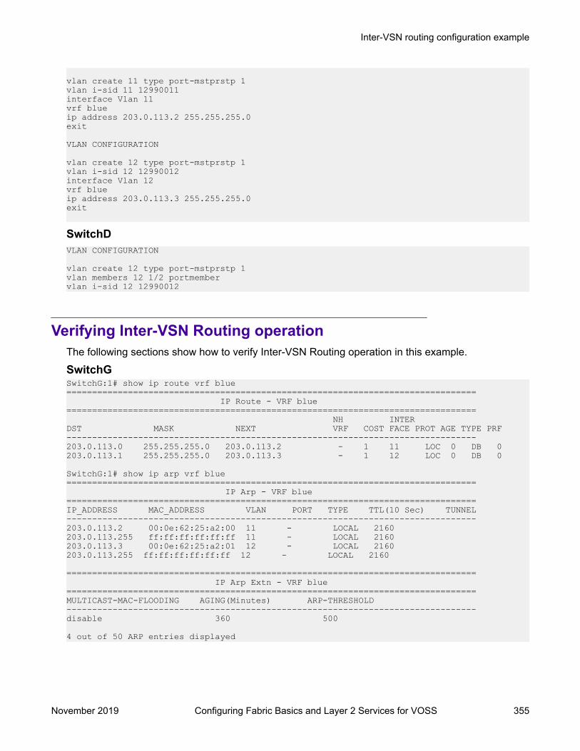
vlan create 11 type port-mstprstp 1vlan i-sid 11 12990011interface Vlan 11vrf blueip address 203.0.113.2 255.255.255.0exit
VLAN CONFIGURATION
vlan create 12 type port-mstprstp 1vlan i-sid 12 12990012interface Vlan 12vrf blueip address 203.0.113.3 255.255.255.0exit
SwitchDVLAN CONFIGURATION
vlan create 12 type port-mstprstp 1vlan members 12 1/2 portmembervlan i-sid 12 12990012
Verifying Inter-VSN Routing operationThe following sections show how to verify Inter-VSN Routing operation in this example.
SwitchGSwitchG:1# show ip route vrf blue================================================================================ IP Route - VRF blue================================================================================ NH INTERDST MASK NEXT VRF COST FACE PROT AGE TYPE PRF--------------------------------------------------------------------------------203.0.113.0 255.255.255.0 203.0.113.2 - 1 11 LOC 0 DB 0203.0.113.1 255.255.255.0 203.0.113.3 - 1 12 LOC 0 DB 0
SwitchG:1# show ip arp vrf blue================================================================================ IP Arp - VRF blue================================================================================IP_ADDRESS MAC_ADDRESS VLAN PORT TYPE TTL(10 Sec) TUNNEL--------------------------------------------------------------------------------203.0.113.2 00:0e:62:25:a2:00 11 - LOCAL 2160203.0.113.255 ff:ff:ff:ff:ff:ff 11 - LOCAL 2160203.0.113.3 00:0e:62:25:a2:01 12 - LOCAL 2160203.0.113.255 ff:ff:ff:ff:ff:ff 12 - LOCAL 2160
================================================================================ IP Arp Extn - VRF blue================================================================================MULTICAST-MAC-FLOODING AGING(Minutes) ARP-THRESHOLD--------------------------------------------------------------------------------disable 360 500
4 out of 50 ARP entries displayed
Inter-VSN routing configuration example
November 2019 Configuring Fabric Basics and Layer 2 Services for VOSS 355
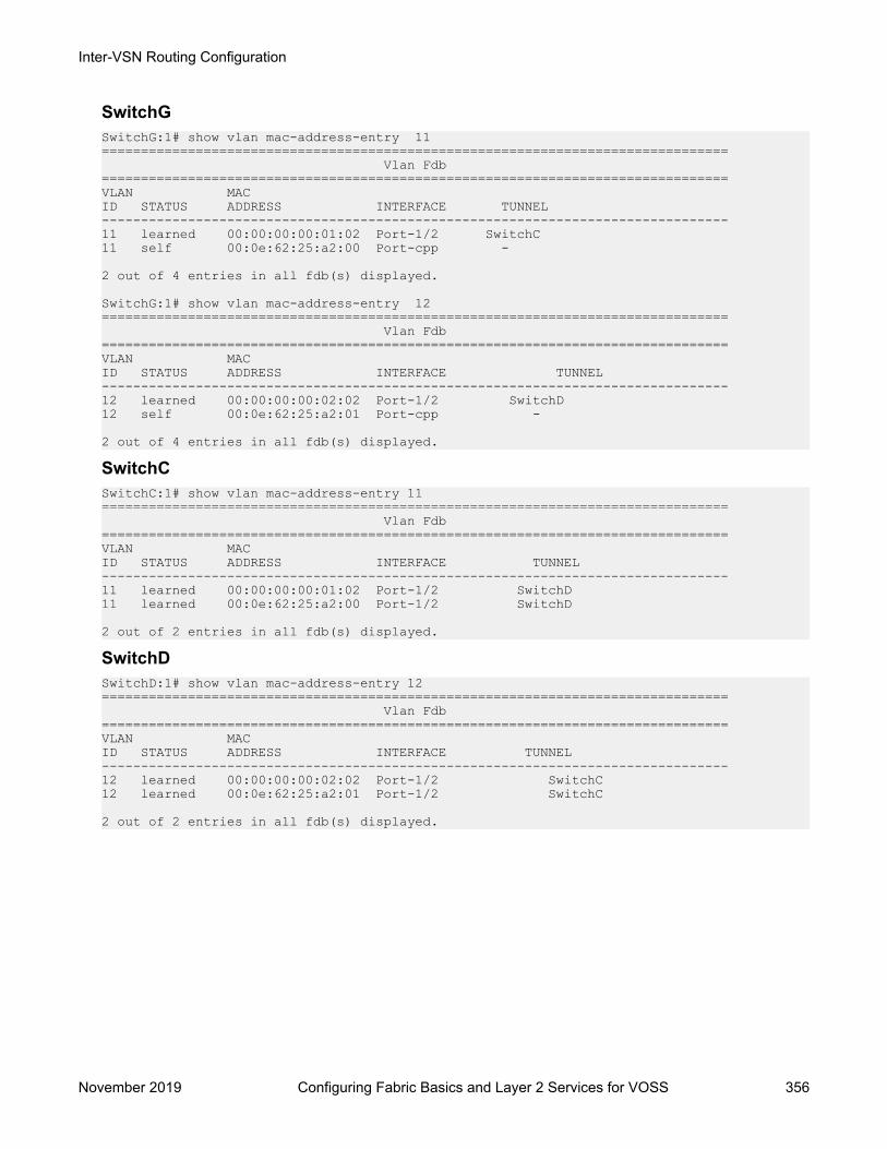
SwitchGSwitchG:1# show vlan mac-address-entry 11================================================================================ Vlan Fdb================================================================================VLAN MACID STATUS ADDRESS INTERFACE TUNNEL--------------------------------------------------------------------------------11 learned 00:00:00:00:01:02 Port-1/2 SwitchC11 self 00:0e:62:25:a2:00 Port-cpp -
2 out of 4 entries in all fdb(s) displayed.
SwitchG:1# show vlan mac-address-entry 12================================================================================ Vlan Fdb================================================================================VLAN MACID STATUS ADDRESS INTERFACE TUNNEL--------------------------------------------------------------------------------12 learned 00:00:00:00:02:02 Port-1/2 SwitchD12 self 00:0e:62:25:a2:01 Port-cpp -
2 out of 4 entries in all fdb(s) displayed.
SwitchCSwitchC:1# show vlan mac-address-entry 11================================================================================ Vlan Fdb================================================================================VLAN MACID STATUS ADDRESS INTERFACE TUNNEL--------------------------------------------------------------------------------11 learned 00:00:00:00:01:02 Port-1/2 SwitchD11 learned 00:0e:62:25:a2:00 Port-1/2 SwitchD
2 out of 2 entries in all fdb(s) displayed.
SwitchDSwitchD:1# show vlan mac-address-entry 12================================================================================ Vlan Fdb================================================================================VLAN MACID STATUS ADDRESS INTERFACE TUNNEL--------------------------------------------------------------------------------12 learned 00:00:00:00:02:02 Port-1/2 SwitchC12 learned 00:0e:62:25:a2:01 Port-1/2 SwitchC
2 out of 2 entries in all fdb(s) displayed.
Inter-VSN Routing Configuration
November 2019 Configuring Fabric Basics and Layer 2 Services for VOSS 356

Appendix A: SPBM ReferenceArchitectures
Reference architecturesSPBM has a straightforward architecture that simply forwards encapsulated C-MACs across thebackbone. Because the B-MAC header stays the same across the network, there is no need toswap a label or perform a route lookup at each node. This architecture allows the frame to follow themost efficient forwarding path from end to end.
The following reference architectures illustrate SPBM with multiple switches in a network.
For information about solution-specific architectures like Video Surveillance or Data Centerimplementation using the VSP switch, see Solution-specific reference architectures on page 367.
The following figure shows the MAC-in-MAC SPBM domain with BEBs on the boundary and BCBsin the core.
The following figure illustrates an existing edge that connects to an SPBM core.
The boundary between the MAC-in-MAC SPBM domain and the 802.1Q domain is handled by theBEBs. At the BEBs, VLANs or VRFs are mapped into I-SIDs based on the local service provisioning.Services (whether Layer 2 or Layer 3 VSNs) only need to be configured at the edge of the SPBMbackbone (on the BEBs). There is no provisioning needed on the core SPBM nodes.
Provisioning an SPBM core is as simple as enabling SPBM and IS-IS globally on all the nodes andon the core facing links. To migrate an existing edge configuration into an SPBM network is just assimple.
November 2019 Configuring Fabric Basics and Layer 2 Services for VOSS 357

Figure 50: SPBM basic architecture
Figure 51: Access to the SPBM Core
All BEBs that have the same I-SID configured can participate in the same VSN. That completes theconfiguration part of the migration and all the traffic flows return to normal operation.
SPBM Reference Architectures
November 2019 Configuring Fabric Basics and Layer 2 Services for VOSS 358

For Layer 3 virtualized routing (Layer 3 VSN), map IPv4-enabled VLANs to VRFs, create an IP VPNinstance on the VRF, assign an I-SID to the VRF, and then configure the desired IP redistribution ofIP routes into IS-IS.
For Layer 2 virtualized bridging (Layer 2 VSN), identify all the VLANs that you want to migrate intoSPBM and assign them to an I-SID on the BEB.
Campus Architecture
For migration purposes, you can add SPBM to an existing network that has SMLT configured. Infact, if there are other protocols already running in the network, such as Open Shortest Path First(OSPF), you can leave them in place too. SPBM uses IS-IS, and operates independently from otherprotocols. However, it is recommended that you eventually eliminate SMLT in the core and eliminateother unnecessary protocols. This reduces the complexity of the network and makes it much simplerto maintain and troubleshoot.
Whether you configure SMLT in the core, the main point to remember is that SPBM separatesservices from the infrastructure. For example, in a large campus, a user may need access to othersites or data centers. With SPBM you can grant that access by associating the user to a specific I-SID. With this mechanism, the user can work without getting access to confidential information ofanother department.
The following figure depicts a topology where the BEBs in the edge and data center distributionnodes are configured in SMLT clusters. Prior to implementing SPBM, the core nodes would alsohave been configured as SMLT clusters. When migrating SPBM onto this network design, it isimportant to note that you can deploy SPBM over the existing SMLT topology without networkinterruption. After the SPBM infrastructure is in place, you can create VSN services over SPBM ormigrate them from the previous end-to-end SMLT-based design.
Reference architectures
November 2019 Configuring Fabric Basics and Layer 2 Services for VOSS 359
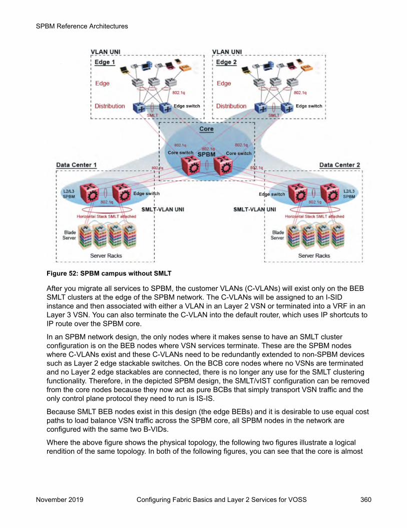
Figure 52: SPBM campus without SMLT
After you migrate all services to SPBM, the customer VLANs (C-VLANs) will exist only on the BEBSMLT clusters at the edge of the SPBM network. The C-VLANs will be assigned to an I-SIDinstance and then associated with either a VLAN in an Layer 2 VSN or terminated into a VRF in anLayer 3 VSN. You can also terminate the C-VLAN into the default router, which uses IP shortcuts toIP route over the SPBM core.
In an SPBM network design, the only nodes where it makes sense to have an SMLT clusterconfiguration is on the BEB nodes where VSN services terminate. These are the SPBM nodeswhere C-VLANs exist and these C-VLANs need to be redundantly extended to non-SPBM devicessuch as Layer 2 edge stackable switches. On the BCB core nodes where no VSNs are terminatedand no Layer 2 edge stackables are connected, there is no longer any use for the SMLT clusteringfunctionality. Therefore, in the depicted SPBM design, the SMLT/vIST configuration can be removedfrom the core nodes because they now act as pure BCBs that simply transport VSN traffic and theonly control plane protocol they need to run is IS-IS.
Because SMLT BEB nodes exist in this design (the edge BEBs) and it is desirable to use equal costpaths to load balance VSN traffic across the SPBM core, all SPBM nodes in the network areconfigured with the same two B-VIDs.
Where the above figure shows the physical topology, the following two figures illustrate a logicalrendition of the same topology. In both of the following figures, you can see that the core is almost
SPBM Reference Architectures
November 2019 Configuring Fabric Basics and Layer 2 Services for VOSS 360
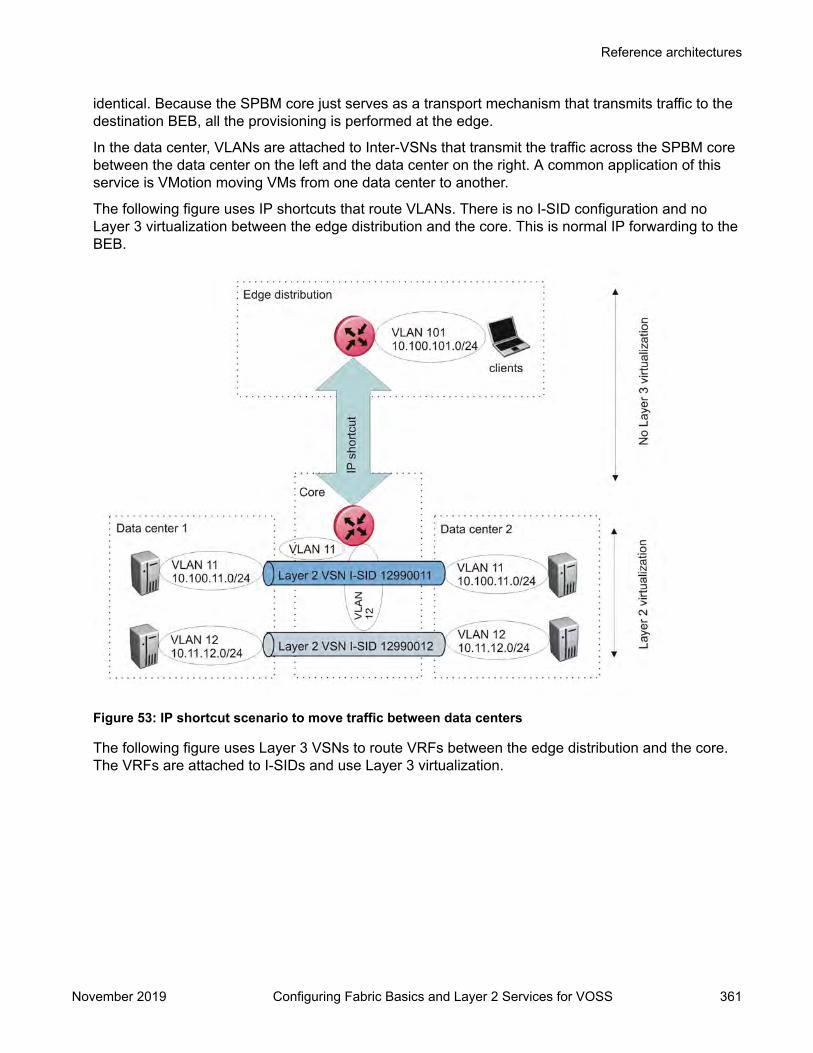
identical. Because the SPBM core just serves as a transport mechanism that transmits traffic to thedestination BEB, all the provisioning is performed at the edge.
In the data center, VLANs are attached to Inter-VSNs that transmit the traffic across the SPBM corebetween the data center on the left and the data center on the right. A common application of thisservice is VMotion moving VMs from one data center to another.
The following figure uses IP shortcuts that route VLANs. There is no I-SID configuration and noLayer 3 virtualization between the edge distribution and the core. This is normal IP forwarding to theBEB.
Figure 53: IP shortcut scenario to move traffic between data centers
The following figure uses Layer 3 VSNs to route VRFs between the edge distribution and the core.The VRFs are attached to I-SIDs and use Layer 3 virtualization.
Reference architectures
November 2019 Configuring Fabric Basics and Layer 2 Services for VOSS 361

Figure 54: VRF scenario to move traffic between data centers
Large data center architectureSPBM supports data centers with IP shortcuts, Layer 2 VSNs, or Layer 3 VSNs. If you use vMotion,you must use Layer 2 between data centers (Layer 2 VSN). With Layer 2 VSNs, you can add IPaddresses to the VLAN on both data centers and run Virtual Router Redundancy Protocol (VRRP)between them to allow the ESX server to route to the rest of the network.
The following figure shows an SPBM topology of a large data center. This figure represents a full-mesh data center fabric using SPBM for storage over Ethernet. This topology is optimized forstorage transport because traffic never travels more than two hops.
Note:
It is recommended that you use a two-tier, full-mesh topology for large data centers.
SPBM Reference Architectures
November 2019 Configuring Fabric Basics and Layer 2 Services for VOSS 362
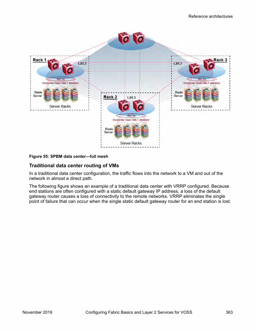
Figure 55: SPBM data center—full mesh
Traditional data center routing of VMsIn a traditional data center configuration, the traffic flows into the network to a VM and out of thenetwork in almost a direct path.The following figure shows an example of a traditional data center with VRRP configured. Becauseend stations are often configured with a static default gateway IP address, a loss of the defaultgateway router causes a loss of connectivity to the remote networks. VRRP eliminates the singlepoint of failure that can occur when the single static default gateway router for an end station is lost.
Reference architectures
November 2019 Configuring Fabric Basics and Layer 2 Services for VOSS 363

Figure 56: Traditional routing before moving VMs
A VM is a virtual server. When you move a VM, the virtual server is moved as is. This action meansthat the IP addresses of that server remain the same after the server is moved from one data centerto the other. This in turn dictates that the same IP subnet (and hence VLAN) exist in both datacenters.In the following figure, the VM moved from the data center on the left to the data center on the right.To ensure a seamless transition that is transparent to the user, the VM retains its networkconnections through the default gateway. This method works, but it adds more hops to all traffic. Asyou can see in the figure, one VM move results in a complicated traffic path. Multiply this with manymoves and soon the network look like a tangled mess that is very inefficient, difficult to maintain,and almost impossible to troubleshoot.
SPBM Reference Architectures
November 2019 Configuring Fabric Basics and Layer 2 Services for VOSS 364

Figure 57: Traditional routing after moving VMs
Optimized data center routing of VMsTwo features make a data center optimized:
• VLAN routers in the Layer 2 domain (green icons)• VRRP BackupMaster
The VLAN routers use lookup tables to determine the best path to route incoming traffic (red dots) tothe destination VM.VRRP BackupMaster solves the problem of traffic congestion on the vIST. Because there can beonly one VRRP Master, all other interfaces are in backup mode. In this case, all traffic is forwardedover the vIST link towards the primary VRRP switch. All traffic that arrives at the VRRP backupinterface is forwarded, so there is not enough bandwidth on the vIST link to carry all the aggregatedriser traffic. VRRP BackupMaster overcomes this issue by ensuring that the vIST trunk is not used insuch a case for primary data forwarding. The VRRP BackupMaster acts as an IP router for packetsdestined for the logical VRRP IP address. All traffic is directly routed to the destined subnetwork andnot through Layer 2 switches to the VRRP Master. This avoids potential limitation in the availablevIST bandwidth.The following figure shows a solution that optimizes your network for bidirectional traffic flows.However, this solution turns two SPBM BCB nodes into BEBs where MAC and ARP learning will beenabled on the Inter-VSN routing interfaces. If you do not care about top-down traffic flows, you canomit the Inter-VSN routing interfaces on the SPBM BCB nodes. This makes the IP routed paths top-down less optimal, but the BCBs remain pure BCBs, thus simplifying core switch configurations.
Reference architectures
November 2019 Configuring Fabric Basics and Layer 2 Services for VOSS 365
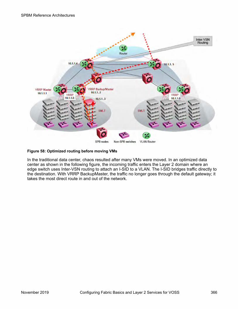
Figure 58: Optimized routing before moving VMs
In the traditional data center, chaos resulted after many VMs were moved. In an optimized datacenter as shown in the following figure, the incoming traffic enters the Layer 2 domain where anedge switch uses Inter-VSN routing to attach an I-SID to a VLAN. The I-SID bridges traffic directly tothe destination. With VRRP BackupMaster, the traffic no longer goes through the default gateway; ittakes the most direct route in and out of the network.
SPBM Reference Architectures
November 2019 Configuring Fabric Basics and Layer 2 Services for VOSS 366

Figure 59: Optimized routing after moving VMs
Solution-specific reference architecturesThe following sections describe solution-specific reference architectures, like for example for VideoSurveillance or Data Center implementation, using the VSP 4000.
Multi-tenant — fabric connectThis fabric connect-based solution leverages the fabric capabilities of the VSP platforms: a VSP7000 core and a VSP 4000 edge. This solution provides the ability to run, by default, up to 24 VRFsfor each wiring closet and is well suited for multi-tenant applications. The zero-touch core is enabledby the fabric connect endpoint provisioning capabilities.
Note:You can increase VRF scaling to run more than 24 VRFs. The maximum number of supportedVRFs and Layer 3 VSNs differs depending on the hardware platform. For more informationabout maximum scaling numbers, see Release Notes for VOSS.
If this solution must support IPv6, then a central router-pair routes all IPv6 traffic. The IPv6 traffic istunneled from each wiring closet to the IPv6 routers by extending Layer 2 VSNs to the q-taggedrouter interfaces.
Solution-specific reference architectures
November 2019 Configuring Fabric Basics and Layer 2 Services for VOSS 367

Figure 60: Small core — multi-tenant
The following list outlines the benefits of the fabric connect-based solution:• Endpoint provisioning• Fast failover• Simple to configure• Layer 2 and Layer 3 virtualized
Hosted data center management solution — E-TreeIn some hosted data center solutions, the hosting center operating company takes responsibility formanaging customer servers. For this shared management, shown in the following figure, serversthat control the operating system level of the production servers, such as the patch level, aredeployed. Because customer production servers do not communicate with each other, a distributedprivate VLAN solution based on fabric connect is deployed to manage all production servers. Thissolution builds a distributed set of E-Trees for each management domain.The VSP switches as access, provide an elegant network-wide E-Tree solution. Spokes, ormanaged servers, cannot communicate to each other over this network, but the sharedmanagement servers on the hub ports can access all spokes. Because of the Layer 2 – E-Treenature of this setup, the managed servers do not require any route entries, and only require one IPinterface in this management private VLAN. This solution supports tagged and untagged physicaland virtual (VM) servers.
SPBM Reference Architectures
November 2019 Configuring Fabric Basics and Layer 2 Services for VOSS 368

Figure 61: Data center hosting private VLAN
The following list outlines the benefits of the hosted data center management solution:• Easy endpoint provisioning• Optimal resiliency• Secure tenant separation
Video surveillance — bridgedIn a video surveillance solution, optimal traffic forwarding is a key requirement to ensure properoperation of the camera and recorder solutions. However, signaling is also important to ensure quickchannel switching. This is achieved by deploying a fabric connect based IP multicast infrastructurethat is optimized for multicast transport, so that the cameras can be selected quickly, and so thatthere is no unnecessary traffic sent across the backbone.
Solution-specific reference architectures
November 2019 Configuring Fabric Basics and Layer 2 Services for VOSS 369

Figure 62: Deployment scenario — bridged video surveillance and IP camera deployment fortransportation, airports, and government
The following list outlines the benefits of the bridged video surveillance solution:• Easy end-point provisioning• sub second resiliency and mc forwarding• secure tenant separation• quick camera switching
Video surveillance — routedIn a video surveillance solution, optimal traffic forwarding is a key requirement to ensure properoperation of the camera and recorder solutions. However, signaling is also important to ensure quickchannel switching. This is achieved by deploying an IP multicast infrastructure that is optimized formulticast transport, so that the cameras can be selected quickly, and so that there is nounnecessary traffic sent across the backbone. In the topology shown in the following figure, eachcamera is attached to its own IP subnet. In a larger topology, this can reduce network overhead. Toincrease network scalability, you can attach a set of cameras to a Layer 2 switch that has IGMP, andthen connect the cameras to the fabric edge (BEB) which has a routing instance.In many customer scenarios, surveillance must be separated from the rest of the infrastructure. Thiscan be achieved by deploying a Layer 3 VSN for the surveillance traffic to keep the surveillancetraffic isolated from any other tenant. For more information, see Configuring Fabric Layer 3 Servicesfor VOSS.
SPBM Reference Architectures
November 2019 Configuring Fabric Basics and Layer 2 Services for VOSS 370

Figure 63: Deployment scenario — Routed video surveillance and IP camera deployment fortransportation, airports, and government
The following list outlines the benefits of the routed video surveillance solution:• Easy endpoint provisioning• Optimal resiliency and mc forwarding• Secure tenant separation• Rapid channel/camera switching
Metro-Ethernet Provider solutionVSP switches provide an end-to-end Metro-Ethernet Provider solution. Leveraging fabric connectthroughout the infrastructure enables a scalable and flexible wholesale provider infrastructure.This use case extends the Transparent Port UNI functionality to transparently forward any customerVLAN across the services.
Solution-specific reference architectures
November 2019 Configuring Fabric Basics and Layer 2 Services for VOSS 371

Figure 64: Metro ring access solution
The following list outlines the benefits of the Metro-Ethernet Provider solution:• Easy endpoint provisioning• Optimal resiliency• Secure tenant separation
SPBM Reference Architectures
November 2019 Configuring Fabric Basics and Layer 2 Services for VOSS 372

Glossary
Autonomous System(AS)
A set of routers under a single technical administration, using a single IGPand common metrics to route packets within the Autonomous System, andusing an EGP to route packets to other Autonomous Systems.
autonomous systemborder router (ASBR)
A router attached at the edge of an OSPF network. An ASBR uses one ormore interfaces that run an interdomain routing protocol such as BGP. Inaddition, a router distributing static routes or Routing Information Protocol(RIP) routes into OSPF is considered an ASBR.
Autonomous SystemNumber (ASN)
A two-byte number that is used to identify a specific AS.
Backbone CoreBridge (BCB)
Backbone Core Bridges (BCBs) form the core of the SPBM network. TheBCBs are SPBM nodes that do not terminate the VSN services. BCBsforward encapsulated VSN traffic based on the Backbone MAC DestinationAddress (B-MAC-DA). A BCB can access information to send that traffic toany Backbone Edge Bridges (BEBs) in the SPBM backbone.
Backbone EdgeBridge (BEB)
Backbone Edge Bridges (BEBs) are SPBM nodes where Virtual ServicesNetworks (VSNs) terminate. BEBs handle the boundary between the coreMAC-in-MAC Shortest Bath Bridging MAC (SPBM) domain and the edgecustomer 802.1Q domain. A BEB node performs 802.1ah MAC-in-MACencapsulation and decapsulation for the Virtual Services Network (VSN).
Backbone MAC (B-MAC)
Provider Backbone Bridging (PBB) MAC-in-MAC encapsulationencapsulates customer MAC addresses in Backbone MAC (B-MAC)addresses. MAC-in-MAC encapsulation defines a BMAC-DA and BMAC-SAto identify the backbone source and destination addresses. The originatingnode creates a MAC header that SPBM uses for delivery from end to end.As the MAC header stays the same across the network, no need exists toswap a label or perform a route lookup at each node, allowing the frame tofollow the most efficient forwarding path end to end. In Shortest PathBridging MAC (SPBM), each node has a System ID, which is used in thetopology announcement. This same System ID also serves as the switchBackbone MAC address (B-MAC), which is used as the source anddestination MAC address in the SPBM network.
Backbone VLANidentifier (B-VID)
The Backbone VLAN identifier (B-VID) indicates the Shortest Path BridgingMAC (SPBM) B-VLAN associated with the SPBM instance.
November 2019 Configuring Fabric Basics and Layer 2 Services for VOSS 373

BGP+ BGP+ is an extension of BGPv4 to support IPv6. BGP+ carries routinginformation for multiple network layer protocol address families, forexample, IPv6 address family and for IP multicast routes.
Circuitless IP (CLIP) A CLIP is often called a loopback and is a virtual interface that does notmap to any physical interface.
Complete SequenceNumber Packets(CSNP)
Complete Sequence Number Packets (CSNP) contain the most recentsequence numbers of all Link State Packets (LSPs) in the database. Whenall routers update their LSP database, synchronization is complete.
Connectivity FaultManagement (CFM)
Connectivity Fault Management is a mechanism to debug connectivityissues and to isolate faults within the Shortest Path Bridging MAC (SPBM)network. CFM operates at Layer 2 and provides the equivalent of ping andtraceroute. IEEE 802.1ag Connectivity Fault Management (CFM) divides orseparates a network into administrative domains called MaintenanceDomains (MD).
Customer MAC (C-MAC)
For customer MAC (C-MAC) addresses, which is customer traffic, toforward across the service provider back, SPBM uses IEEE 802.1ahProvider Backbone Bridging MAC-in-MAC encapsulation. The systemencapsulates C-MAC addresses within a backbone MAC (B-MAC) addresspair made up of a BMAC destination address (BMAC-DA) and a BMACsource address (BMAC-SA).
Customer VLAN (C-VLAN)
A traditional VLAN with MAC learning and flooding, where user devicesconnect to the network. In SPBM, C-VLANs are mapped to a ServiceInstance Identifier (I-SID) at the Backbone Edge Bridges (BEBs).
Data I-SID In SPBM, the data I-SID is allocated by the Backbone Edge Bridge (BEB)when the multicst stream reaches the BEB. The data I-SID uses Tx/Rx bitsto signify whether the BEB uses the I-SID to transmit, receive, or bothtransmit and receive data on that I-SID. Data is transported from the senderto the receiver across the SPBM cloud using the data I-SID.
DesignatedIntermediate System(DIS)
A Designated Intermediate System (DIS) is the designated router inIntermediate System to Intermediate System (IS-IS) terminology. You canmodify the priority to affect the likelihood of a router being elected thedesignated router. The higher the priority, the more likely the router is to beelected as the DIS. If two routers have the same priority, the router with thehighest MAC address (Sequence Number Packet [SNP] address) is electedas the DIS.
designated router(DR)
A single router elected as the designated router for the network. In abroadcast or nonbroadcast multiple access (NBMA) network running theOpen Shortest Path First (OSPF) protocol, a DR ensures all networkrouters synchronize with each other and advertises the network to the restof the Autonomous System (AS). In a multicast network running ProtocolIndependent Multicast (PIM), the DR acts as a representative router for
Glossary
November 2019 Configuring Fabric Basics and Layer 2 Services for VOSS 374
directly connected hosts. The DR sends control messages to therendezvous point (RP) router, sends register messages to the RP on behalfof directly connected sources, and maintains RP router status informationfor the group.
Enterprise DeviceManager (EDM)
A web-based embedded management system to support single-elementmanagement. EDM provides complete configuration managementfunctionality for the supported devices and is supplied to the customer asembedded software in the device.
equal cost multipath(ECMP)
Distributes routing traffic among multiple equal-cost routes.
Global routingengine (GRE)
The base router or routing instance 0 in the Virtual Routing and Forwarding(VRF).
Global Routing Table(GRT)
The Global Routing Table (GRT) is a table that maintains the informationneeded to forward an IP packet along the best route.
graphical userinterface (GUI)
A graphical (rather than textual) computer interface.
IEEE 802.1aq IEEE 802.1aq is the standard for Shortest Path Bridging MAC (SPBM).SPBM makes network virtualization much easier to deploy within, reducingthe complexity of the network while at the same time providing greaterscalability. SPBM eliminates the need for multiple overlay protocols in thecore of the network by reducing the core to a single Ethernet based linkstate protocol which can provide virtualization services, both layer 2 andlayer 3, using a pure Ethernet technology base.
Institute of Electricaland ElectronicsEngineers (IEEE)
An international professional society that issues standards and is a memberof the American National Standards Institute, the International StandardsInstitute, and the International Standards Organization.
Interior GatewayProtocol (IGP)
Distributes routing information between routers that belong to a singleAutonomous System (AS).
Intermediate Systemto IntermediateSystem (IS-IS)
Intermediate System to Intermediate System( IS-IS) is a link-state, interiorgateway protocol. ISO terminology refers to routers as IntermediateSystems (IS), hence the name Intermediate System to Intermediate System(IS-IS). IS-IS operation is similar to Open Shortest Path First (OSPF).
In Shortest Path Bridging MAC (SPBM) networks, IS-IS discovers networktopology and builds shortest path trees between network nodes that IS-ISuses for forwarding unicast traffic and determining the forwarding table formulticast traffic. SPBM employs IS-IS as the interior gateway protocol andimplements additional Type-Length-Values (TLVs) to support additionalfunctionality.
Enterprise Device Manager (EDM)
November 2019 Configuring Fabric Basics and Layer 2 Services for VOSS 375

Internet ProtocolSecurity (IPsec)
Internet Protocol security (IPsec) is a set of security protocols andcryptographic algorithms that protect communication in a network. UseIPsec in scenarios where you need to encrypt packets between two hosts,two routers, or a router and a host.
interswitch trunking(IST)
A feature that uses one or more parallel point-to-point links to connect twoaggregation switches. The two aggregation switches use this channel toshare information and operate as a single logical switch. Only oneinterswitch trunk can exist on each Split Multilink Trunking (SMLT)aggregation switch.
IS-IS Hello packets Intermediate System to Intermediate System (IS-IS) uses Hello packets toinitialize and maintain adjacencies between neighboring routers. IS-IS Hellopackets contain the IP address of the interface over which the Hellotransmits. These packets are broadcast to discover the identities ofneighboring IS-IS systems and to determine whether the neighbor is aLevel 1 router.
Layer 1 Layer 1 is the Physical Layer of the Open System Interconnection (OSI)model. Layer 1 interacts with the MAC sublayer of Layer 2, and performscharacter encoding, transmission, reception, and character decoding.
Layer 2 Layer 2 is the Data Link Layer of the OSI model. Examples of Layer 2protocols are Ethernet and Frame Relay.
Layer 2 VirtualServices Network
The Layer 2 Virtual Services Network (L2 VSN) feature provides IPconnectivity over SPBM for VLANs. Backbone Edge Bridges (BEBs) handleLayer 2 virtualization. At the BEBs you map the end-user VLAN to aService Instance Identifier (I-SID). BEBs that have the same I-SIDconfigured can participate in the same Layer 2 Virtual Services Network(VSN).
Layer 3 Layer 3 is the Network Layer of the OSI model. An example of a Layer 3protocol is Internet Protocol (IP).
Layer 3 VirtualServices Network
The Layer 3 Virtual Services Network (L3 VSN) feature provides IPconnectivity over SPBM for VRFs. Backbone Edge Bridges (BEBs) handleLayer 3 virtualized. At the BEBs through local provisioning, you map theend-user IP enabled VLAN or VLANs to a Virtualized Routing andForwarding (VRF) instance. Then you map the VRF to a Service InstanceIdentifier (I-SID). VRFs that have the same I-SID configured can participatein the same Layer 3 Virtual Service Network (VSN).
Layer 4 The Transport Layer of the OSI model. An example of a Layer 4 protocol isTransmission Control Protocol (TCP).
Link Layer DiscoveryProtocol (LLDP)
Link Layer Discovery Protocol is used by network devices to advertise theiridentities. Devices send LLDP information at fixed intervals in the form of
Glossary
November 2019 Configuring Fabric Basics and Layer 2 Services for VOSS 376
Ethernet frames, with each frame having one Link Layer Discovery ProtocolData Unit.
Link State Packets(LSP)
Link State Packets (LSP) contain information about the state of adjacenciesor defined and distributed static routes. Intermediate System toIntermediate System (IS-IS) exchanges this information with neighboringIS-IS routers at periodic intervals. Every router in the domain has anidentical link state database and each runs shortest path first to calculateroutes.
Link State ProtocolData Unit (LSPDUs)
Link State Protocol Data Unit is similar to a Link State Advertisement inOpen Shortest Path First (OSPF). Intermediate System to IntermediateSystem (IS-IS) runs on all nodes of Shortest Path Bridging-MAC (SPBM).Since IS-IS is the basis of SPBM, the device must first form the IS-ISadjacency by first sending out hellos and then Link State Protocol DataUnits. After the hellos are confirmed both nodes sends Link State ProtocolData Units (LSPDUs) that contain connectivity information for the SPBMnode. These nodes also send copies of all other LSPDUs they have in theirdatabases. This establishes a network of connectivity providing thenecessary information for each node to find the best and proper path to alldestinations in the network.
link trace message The link trace message (LTM) is often compared to traceroute. A MEPtransmits the LTM packet. This packet specifies the target MAC address ofan MP, which is the SPBM system id or the virtual SMLT MAC. MPs on thepath to the target address respond with an LTR. LTM contains:
• Time to live (TTL)
• Transaction Identifier
• Originator MAC address
• Target MAC address
link-state database(LSDB)
A database built by each OSPF router to store LSA information. The routeruses the LSDB to calculate the shortest path to each destination in theautonomous system (AS), with itself at the root of each path.
Local Area Network(LAN)
A data communications system that lies within a limited spatial area, uses aspecific user group and topology, and can connect to a public switchedtelecommunications network (but is not one).
Loopback Messages(LBM)
A Loopback Message (LBM) is a unicast message triggered by the operatorissuing an operational command. LBM can be addressed to either aMaintenance End Point (MEP) or Maintenance Intermediate Point (MIP),but only a MEP can initiate an LBM. The destination MP can be addressedby its MAC address. The receiving MP responds with a LoopbackResponse (LBR). LBM can contain an arbitrary amount of data that can beused to diagnose faults as well as performance measurements. The
Link State Packets (LSP)
November 2019 Configuring Fabric Basics and Layer 2 Services for VOSS 377

receiving MP copies the data to the LBR. The system achieves faultverification through the use of Loopback Messages (LBM).
Loopback Response(LBR)
Loopback Response (LBR) is the response from a Maintenance Point (MP).
MAC-in-MACencapsulation
MAC-in-MAC encapsulation defines a BMAC-DA and BMAC-SA to identifythe backbone source and destination addresses. The originating nodecreates a MAC header that the device uses for delivery from end to end. Asthe MAC header stays the same across the network, there is no need toswap a label or do a route lookup at each node, allowing the frame to followthe most efficient forwarding path end to end.
MaintenanceAssociations (MA)
Maintenance Associations (MA) are administrative associations in anetwork that is divided by the 802.1ag Connectivity Fault Management(CFM) feature. CFM groups MAs within Maintenance Domains. Each MA isdefined by a set of Maintenance Points (MP). An MP is a demarcation pointon an interface that participates in CFM within an MD. Connectivity FaultManagement is a mechanism to debug connectivity issues and to isolatefaults within the Shortest Path Bridging MAC (SPBM) Network.
MaintenanceDomains (MD)
Maintenance Domains (MD) are administrative domains that divides anetwork by the 802.1ag Connectivity Fault Management (CFM) feature.Each MD is further subdivided into logical groupings called MaintenanceAssociations (MA). Connectivity Fault Management is a mechanism todebug connectivity issues and to isolate faults within the Shortest PathBridging MAC (SPBM) Network.
Maintenance Points(MP)
Maintenance Points (MP) are a demarcation point on an interface thatparticipates in Connectivity Fault Management (CFM) within a MaintenanceDomain (MD). There are two types of MP: Maintenance End Point (MEP)and Maintenance Intermediate Point (MIP). Connectivity Fault Managementis a mechanism to debug connectivity issues and to isolate faults within theShortest Path Bridging MAC (SPBM) Network.
MD5 Authentication MD5 authentication creates an encoded checksum in the transmittedpacket. The receiving router uses an authentication key (password) to verifythe packet’s MD5 checksum. There is an optional key ID.
Media AccessControl (MAC)
Arbitrates access to and from a shared medium.
MultiLink Trunking(MLT)
A method of link aggregation that uses multiple Ethernet trunks aggregatedto provide a single logical trunk. A multilink trunk provides the combinedbandwidth of multiple links and the physical layer protection against thefailure of a single link.
Glossary
November 2019 Configuring Fabric Basics and Layer 2 Services for VOSS 378

Network Entity Title(NET)
The Network Entity Title (NET) is the combination of all three globalparameters: Manual area, System ID and NSEL.
• Manual area — The manual area or area ID is up to 13 bytes long.The first byte of the area number (for example, 49) is the Authority andFormat Indicator (AFI). The next bytes are the assigned domain (area)identifier, which is up to 12 bytes (for example,49.0102.0304.0506.0708.0910.1112).
• System ID — The system ID is any 6 bytes that are unique in a givenarea or level. The system ID defaults to the node BMAC.
• NSEL — The last byte (00) is the n-selector.
In the Ethernet Routing Switch 8800/8600 implementation, this part isautomatically attached. There is no user input accepted.
Open Shortest PathFirst (OSPF)
A link-state routing protocol used as an Interior Gateway Protocol (IGP).
Partial SequenceNumber Packets(PSNP)
Partial Sequence Number Packets (PSNP) are requests for missing LinkState Packets (LSPs). When a receiving router detects a missing LSP, itsends a PSNP to the router that sent the Complete Sequence NumberPackets (CSNP).
port A physical interface that transmits and receives data.
Protocol Data Units(PDUs)
A unit of data that is specified in a protocol of a specific layer and thatconsists of protocol-control information of the specific layer and possiblyuser data of that layer.
Provider BackboneBridge (PBB)
To forward customer traffic across the service-provider backbone, SPBMuses IEEE 802.1ah Provider Backbone Bridging (PBB) MAC-in-MACencapsulation, which hides the customer MAC (C-MAC) addresses in abackbone MAC (B-MAC) address pair. MAC-in-MAC encapsulation definesa BMAC-DA and BMAC-SA to identify the backbone source and destinationaddresses.
rendezvous point(RP)
The root of the shared tree. One RP exists for each multicast group. TheRP gathers information about available multicast services through thereception of control messages and the distribution of multicast groupinformation. Protocol Independent Multicast (PIM) uses RPs.
reverse pathchecking (RPC)
Prevents packet forwarding for incoming IP packets with incorrect or forged(spoofed) IP addresses.
reverse pathforwarding (RPF)
Prevents a packet from forging its source IP address. Typically, the systemexamines and validates the source address of each packet.
Network Entity Title (NET)
November 2019 Configuring Fabric Basics and Layer 2 Services for VOSS 379

Routing InformationProtocol (RIP)
A distance vector protocol in the IP suite, used by IP network-layer protocol,that enables routers in the same AS to exchange routing information bymeans of periodic updates. You often use RIP as a very simple interiorgateway protocol (IGP) within small networks.
scope level In IP Multicast over Fabric Connect, the scope level is the level in which themulticast stream is constrained. For instance, if a sender sends a multicaststream to a BEB on a Layer 2 Virtual Services Network (VSN) onlyreceivers that are part of a Layer 2 VSN can receive that stream. Similarly,if a sender sends a multicast stream to a BEB on a Layer 3 VSN onlyreceivers that are part of a Layer 3 VSN can receive that stream.
Service InstanceIdentifier (I-SID)
The SPBM B-MAC header includes a Service Instance Identifier (I-SID)with a length of 24 bits. SPBM uses this I-SID to identify and transmit anyvirtualized traffic in an encapsulated SPBM frame. SPBM uses I-SIDs tovirtualize VLANs (Layer 2 Virtual Services Network [VSN]) or VRFs (Layer 3Virtual Services Network [VSN]) across the MAC-in-MAC backbone. WithLayer 2 VSNs, you associate the I-SID with a customer VLAN, which isthen virtualized across the backbone. With Layer 3 VSNs, you associatethe I-SID with a customer VRF, which is also virtualized across thebackbone.
Shortest PathBridging (SPB)
Shortest Path Bridging is a control Link State Protocol that provides a loop-free Ethernet topology. There are two versions of Shortest Path Bridge:Shortest Path Bridging VLAN and Shortest Path Bridging MAC. ShortestPath Bridging VLAN uses the Q-in-Q frame format and encapsulates thesource bridge ID into the VLAN header. Shortest Path Bridging MAC usesthe 802.1 ah MAC-in-MAC frame format and encapsulates the sourcebridge identifier into the B-MAC header.
Shortest PathBridging MAC(SPBM)
Shortest Path Bridging MAC (SPBM) uses the Intermediate-System-to-Intermediate-System (IS-IS) link-state routing protocol to provide a loop-free Ethernet topology that creates a shortest-path topology from everynode to every other node in the network based on node MAC addresses.SPBM uses the 802.1ah MAC-in-MAC frame format and encapsulates thesource bridge identifier into the B-MAC header. SPBM eliminates the needfor multiple overlay protocols in the core of the network by reducing thecore to a single Ethernet-based link-state protocol, which can providevirtualization services, both layer 2 and layer 3, using a pure Ethernettechnology base.
shortest path first(SPF)
A class of routing protocols that use Djikstra's algorithm to compute theshortest path through a network, according to specified metrics, for efficienttransmission of packet data.
Glossary
November 2019 Configuring Fabric Basics and Layer 2 Services for VOSS 380

shortest path tree(SPT)
Creates a direct route between the receiver and the source for groupmembers in a Protocol Independent Multicast-Sparse Mode (PIM-SM)domain.
Split MultiLinkTrunking (SMLT)
An extension to IEEE 802.1AX (link aggregation), provides nodal and linkfailure protection and flexible bandwidth scaling to improve on the level ofLayer 2 resiliency.
time-to-live (TTL) The field in a packet used to determine the valid duration for the packet.The TTL determines the packet lifetime. The system discards a packet witha TTL of zero.
Top of Rack (TOR) A Top of Rack (TOR) switch refers to a switch that sits at the top or near thetop of a rack often found in data centers.
Virtual LinkAggregation ControlProtocol (VLACP)
Virtual Link Aggregation Control Protocol (VLACP) is a Layer 2handshaking protocol that can detect end-to-end failure between twophysical Ethernet interfaces.
Virtual Local AreaNetwork (VLAN)
A Virtual Local Area Network is a group of hosts that communicate as ifthey are attached to the same broadcast domain regardless of theirphysical location. VLANs are layer 2 constructs.
Virtual PrivateNetwork (VPN)
A Virtual Private Network (VPN) requires remote users to be authenticatedand ensures private information is not accessible to unauthorized parties. AVPN can allow users to access network resources or to share data.
VLAN Identifier (VID) VLAN Identifier (VID) is a data field in IEEE 802.1Q VLAN tagging.
shortest path tree (SPT)
November 2019 Configuring Fabric Basics and Layer 2 Services for VOSS 381