Embed Size (px)
Citation preview
Configuration Manual Edition 12/2004
sinamics SINAMICS S120 Synchronous Motors 1FK7


Foreword
Motor Description 1
Electrical Connections 2
3
Motor Components (Options) 4
Dimension Drawings 5
Appendix A
Technical Data and Speed-Torque Diagrams
SINAMICS
SINAMICS S120 1FK7 SINAMICS Synchronous Motors
Configuration Manual
(PFK7S), Edition 12.2004 6SN1197-0AD16-0BP0
Safety Guidelines
This manual contains notices you have to observe in order to ensure your personal safety, as well as to prevent damage to property. The notices referring to your personal safety are highlighted in the manual by a safety alert symbol, notices referring to property damage only have no safety alert symbol. These notices shown below are graded according to the degree of danger.
Danger
indicates that death or severe personal injury will result if proper precautions are not taken.
Warning
indicates that death or severe personal injury may result if proper precautions are not taken.
Caution
with a safety alert symbol, indicates that minor personal injury can result if proper precautions are not taken.
Caution
without a safety alert symbol, indicates that property damage can result if proper precautions are not taken.
Notice
indicates that an unintended result or situation can occur if the corresponding information is not taken into account.
If more than one degree of danger is present, the warning notice representing the highest degree of danger will be used. A notice warning of injury to persons with a safety alert symbol may also include a warning relating to property damage.
Qualified Personnel The device/system may only be set up and used in conjunction with this documentation. Commissioning and operation of a device/system may only be performed by qualified personnel. Within the context of the safety notes in this documentation qualified persons are defined as persons who are authorized to commission, ground and label devices, systems and circuits in accordance with established safety practices and standards.
Prescribed Usage Note the following:
Warning
This device may only be used for the applications described in the catalog or the technical description and only in connection with devices or components from other manufacturers which have been approved or recommended by Siemens. Correct, reliable operation of the product requires proper transport, storage, positioning and assembly as well as careful operation and maintenance.
Trademarks All names identified by ® are registered trademarks of the Siemens AG. The remaining trademarks in this publication may be trademarks whose use by third parties for their own purposes could violate the rights of the owner.
Copyright Siemens AG 2004. All rights reserved.
Disclaimer of Liability We have reviewed the contents of this publication to ensure consistency with the hardware and software described. Since variance cannot be precluded entirely, we cannot guarantee full consistency. However, the information in this publication is reviewed regularly and any necessary corrections are included in subsequent editions.
Siemens AG rives
Postfach 4848, 90327 Nuremberg, Germany Siemens AG 2004 Technical data subject to change
Siemens Aktiengesellschaft 6SN1197-0AD16-0BP0
Automation and D
Designation of the documentation
Printing history
Brief details of this edition and previous editions are listed below.
The status of each edition is shown by the code in the ”Remarks” column.
Status code in the ”Remarks” column:
A New documentation
B Unrevised reprint with new Order No.
C Revised edition with new status
If factual changes have been made on the page since the last edition, this is indicated by a new edition coding in the header on
that page.
Edition Order No. for 1FK7 Remarks
12.04 6SN1197-0AD16-0BP0 A
Trademarks
SINAMICS®, SIMOTION®, SIMATIC®, SIMATIC HMI®, SIMATIC NET®, SIROTEC®, SINUMERIK®, SIMODRIVE®, SIEMOSYN®,
SIMOVERT MASTERDRIVES® and MOTION-CONNECT® are registered trademarks of Siemens AG. Other names in this
publication might be trademarks whose use by a third party for his own purposes may violate the rights of the registered holder.
Further information is available on the Internet under:
http://www.siemens.com/motioncontrol
This publication was produced with SIPS+
© Siemens AG 2004. All rights reserved.
The control system may support functions that are not described in
this documentation. However, no claim can be made regarding the
availability of these functions when the equipment is first supplied or
in the event of servicing.
We have checked that the contents of this document correspond to
the hardware and software described. Nonetheless, differences might
exist and therefore we cannot guarantee that they are completely identical.
The information given in this publication is reviewed at regular intervals
and any corrections that might be necessary are made in the subsequent
printings. Suggestions for improvement are also welcome.
We reserve the right to make technical changes.
Order No. 6SN1197-0AD16-0BP0
Printed in the Federal Republic of Germany
Siemens–Aktiengesellschaft

Foreword Information on the documentation
This document is part of the Technical Customer Documentation which has been developed for the SINAMICS S120 system. All of the documents are available individually. The documentation list, which includes all Advertising Brochures, Catalogs, Overviews, Short Descriptions, Operating Instructions and Technical Descriptions with Order No., ordering address and price can be obtained from your local Siemens office.
This document does not purport to cover all details or variations in equipment, nor to provide for every possible contingency to be met in connection with installation, operation or maintenance.
We would also like to point-out that the contents of this document are neither part of nor modify any prior or existing agreement, commitment or contractual relationship. The sales contract contains the entire obligations of Siemens. The warranty contained in the contract between the parties is the sole warranty of Siemens. Any statements contained herein neither create new warranties nor modify the existing warranty.
Structure of the documentation for 1FK and 1FT motors
Table 1 Configuration Manual, individual sections
Title Order No. (MLFB) Language Synchronous Motors, General Section for SIMODRIVE, SIMOVERT MASTERDRIVES and SINAMICS S120
6SN1197–0AD07–0AP⃞ German
Synchronous Motors, 1FK7 Motor Section for SINAMICS S120
6SN1197–0AD16–0AP⃞ German
Synchronous Motors, 1FT6 Motor Section for SINAMICS S120
6SN1197–0AD12–0AP⃞ German
Hotline
If you have any questions, please contact the following Hotline:
A&D Technical Support Phone: +49 (180) 5050–222 Fax: +49 (180) 5050–223 http://www.siemens.de/automation/support-request
If you have any questions regarding the documentation (suggestions, corrections) then please send a fax to the following number:
+49 (9131) 98–2176
Fax form: Refer to the response sheet at the end of the document
1FK7 SINAMICS synchronous motors Configuration Manual, (PFK7S), 12.2004 Edition, 6SN1197-0AD16-0BP0 iii
Foreword
Danger and warning information
Danger
Start-up/commissioning is absolutely prohibited until it has been completely ensured that the machine, in which the components described here are to be installed, is in full compliance with the specifications of Directive 98/37/EC.
SINAMICS devices and synchronous motors may only be commissioned by suitably qualified personnel.
This personnel must carefully observe the technical customer documentation associated with this product and be knowledgeable about and carefully observe the danger and warning information.
Operational electrical equipment and motors have parts and components which are at hazardous voltage levels.
When the machine or system is operated, hazardous axis movements can occur.
All of the work carried-out on the electrical machine or system must be carried-out with it in a no-voltage condition.
SINAMICS drive units are designed for operation on low-ohmic, grounded line supply systems (TN line supply systems).
Warning
The successful and safe operation of this equipment and motors is dependent on professional transport, storage, installation and mounting as well as careful operator control, service and maintenance.
For special versions of the drive units and motors, information and data in the catalogs and quotations additionally apply.
In addition to the danger and warning information/instructions in the technical customer documentation supplied, the applicable domestic, local and plant-specific regulations and requirements must be carefully taken into account.
Caution
The motors can have surface temperatures of over +80 °C.
This is the reason that temperature-sensitive components, e.g. cables or electronic components may neither be in contact nor be attached to the motor.
When connecting-up cables, please observe that they – are not damaged – are not subject to tensile stress – cannot be touched by rotating components.
1FK7 SINAMICS synchronous motors iv Configuration Manual, (PFK7S), 12.2004 Edition, 6SN1197-0AD16-0BP0

Foreword
Caution
The DRIVE-CLiQ interface contains motor and encoder-specific data as well as an electronic rating plate. This is the reason that this Sensor Module may only be operated on the original motor - and may not be mounted onto other motors or replaced by a sensor module from other motors.
The DRIVE-CLiQ interface has direct contact to components that can be damaged/destroyed by electrostatic discharge (ESDS). Neither hands nor tools that could be electrostatically charged may come into contact with the connections.
Caution
SINAMICS drive units with synchronous motors are subject, as part of the routine test, to a voltage test in accordance with EN 50178. While the electrical equipment of industrial machines is being subject to a voltage test in accordance with EN60204-1, Section 19.4, all SINAMICS drive unit connections must be disconnected/withdrawn in order to avoid damaging the SINAMICS drive units.
Motors should be connected-up according to the circuit diagram provided. It is not permissible to directly connect the motors to the three-phase line supply. Motors will be destroyed if they are connected directly to the three-phase line supply.
Note
SINAMICS units with synchronous motors fulfill, when operational and in dry operating rooms, the Low-Voltage Directive 73/23/EEC.
SINAMICS units with synchronous motors fulfill, in the configuration specified in the associated EC Declaration of Conformity, the EMC Directive 89/336/EEC.
1FK7 SINAMICS synchronous motors Configuration Manual, (PFK7S), 12.2004 Edition, 6SN1197-0AD16-0BP0 v

Foreword
ESDS instructions
Caution
ElectroStatic-Sensitive Devices (ESDS) are individual components, integrated circuits, or modules that can be damaged by electrostatic fields or discharges.
ESDS regulations for handling boards and equipment:
When handling components that can be destroyed by electrostatic discharge, it must be ensured that personnel, the workstation and packaging are well grounded!
Personnel in ESD zones with conductive floors may only touch electronic components if they are – grounded through an ESDS bracelet and – wearing ESDS shoes or ESDS shoe grounding strips.
Electronic boards may only be touched when absolutely necessary.
Electronic boards may not be brought into contact with plastics and articles of clothing manufactured from man-made fibers.
Electronic boards may only be placed on conductive surfaces (table with ESDS surface, conductive ESDS foam rubber, ESDS packing bag, ESDS transport containers).
Electronic boards may not be brought close to data terminals, monitors or television sets. Minimum clearance to screens > 10 cm).
Measurements may only be carried-out on electronic boards and modules if – the measuring instrument is grounded (e.g. via a protective conductor) or – before making measurements with a potential-free measuring device, the measuring head is briefly discharged (e.g. by touching an unpainted blank piece of metal on the control cabinet).
Standards, regulations The appropriate standards, regulations are directly assigned to the functional requirements.
1FK7 SINAMICS synchronous motors vi Configuration Manual, (PFK7S), 12.2004 Edition, 6SN1197-0AD16-0BP0
Table of Contents Foreword ...................................................................................................................................................... iii
1 Motor Description ...................................................................................................................................... 1-1
1.1 Features ..................................................................................................................................... 1-1
1.2 Technical ................................................................................................................................... 1-2
1.3 Order designation ...................................................................................................................... 1-4 1.3.1 1FK7 Compact motors - core type, non-ventilated .................................................................... 1-4 1.3.2 1FK7 High Dynamic motors - core type, non-ventilated ............................................................ 1-6
1.4 Armature short-circuit braking.................................................................................................... 1-8
1.5 Coupling ................................................................................................................................... 1-10
2 Electrical Connections............................................................................................................................... 2-1
2.1 Connection overview.................................................................................................................. 2-1
2.2 Power connection ...................................................................................................................... 2-2
2.3 DRIVE-CLiQ............................................................................................................................... 2-3
2.4 Motors with DRIVE-CLiQ ........................................................................................................... 2-3
2.5 Motors without DRIVE-CLiQ ...................................................................................................... 2-4
2.6 Rotating the connector at the motor .......................................................................................... 2-4
3 Technical Data and Speed-Torque Diagrams........................................................................................... 3-1
3.1 Introduction ................................................................................................................................ 3-1
3.2 Speed-torque diagrams 1FK7 CT.............................................................................................. 3-2
3.3 Speed-torque diagrams 1FK7 HD ........................................................................................... 3-26
3.4 Cantilever force diagrams ........................................................................................................ 3-40
3.5 Axial forces............................................................................................................................... 3-44
4 Motor Components (Options).................................................................................................................... 4-1
4.1 Thermal motor protection........................................................................................................... 4-1
4.2 Encoders .................................................................................................................................... 4-3 4.2.1 Encoder overview ...................................................................................................................... 4-3 4.3 Motors with DRIVE-CLiQ ........................................................................................................... 4-4 4.4 Motors without DRIVE-CLiQ ...................................................................................................... 4-5 4.4.1 Incremental encoders ................................................................................................................ 4-5 4.4.2 Absolute value encoder ............................................................................................................. 4-8 4.4.3 Resolvers ................................................................................................................................. 4-10
4.5 Holding brake (option).............................................................................................................. 4-12
4.6 Planetary gearbox (option)....................................................................................................... 4-13
1FK7 SINAMICS synchronous motors Configuration Manual, (PFK7S), 12.2004 Edition, 6SN1197-0AD16-0BP0 vii

Table of Contents
5 Dimension Drawings.................................................................................................................................. 5-1
5.1 Introduction ................................................................................................................................ 5-1
5.2 1FK7 CT with DRIVE-CLiQ........................................................................................................ 5-2
5.3 1FK7 HD with DRIVE-CLiQ...................................................................................................... 5-10
5.4 1FK7 CT without DRIVE-CLiQ................................................................................................. 5-14
5.5 1FK7 HD without DRIVE-CLiQ ................................................................................................ 5-22
A Appendix....................................................................................................................................................A-1
A.1 References.................................................................................................................................A-1
Index
1FK7 SINAMICS synchronous motors viii Configuration Manual, (PFK7S), 12.2004 Edition, 6SN1197-0AD16-0BP0

Table of Contents
Tables
Table 1 Configuration Manual, individual sections .................................................................................... iii Table 1-1 Technical data, 1FK7 motor....................................................................................................... 1-2 Table 1-2 Resistor braking for 1FK7 CT and 1FK7 HD ............................................................................. 1-9 Table 1-3 Assignment of the coupling outputs to the motors................................................................... 1-10 Table 2-1 Direction of rotation and torques when rotating the connector .................................................. 2-5 Table 3-1 1FK7022 CT............................................................................................................................... 3-2 Table 3-2 1FK7032 CT............................................................................................................................... 3-4 Table 3-3 1FK7040 CT............................................................................................................................... 3-6 Table 3-4 1FK7042 CT............................................................................................................................... 3-8 Table 3-5 1FK7060 CT............................................................................................................................. 3-10 Table 3-6 1FK7063 CT............................................................................................................................. 3-12 Table 3-7 1FK7080 CT............................................................................................................................. 3-14 Table 3-8 1FK7083 CT............................................................................................................................. 3-16 Table 3-9 1FK7100 CT............................................................................................................................. 3-18 Table 3-10 1FK7101 CT............................................................................................................................. 3-20 Table 3-11 1FK7103 CT............................................................................................................................. 3-22 Table 3-12 1FK7105 CT............................................................................................................................. 3-24 Table 3-13 1FK7033 HD ............................................................................................................................ 3-26 Table 3-14 1FK7043 HD ............................................................................................................................ 3-28 Table 3-15 1FK7044 HD ............................................................................................................................ 3-30 Table 3-16 1FK7061 HD ............................................................................................................................ 3-32 Table 3-17 1FK7064 HD ............................................................................................................................ 3-34 Table 3-18 1FK7082 HD ............................................................................................................................ 3-36 Table 3-19 1FK7085 HD ............................................................................................................................ 3-38 Table 3-20 Explanation of the formula abbreviations................................................................................. 3-40 Table 4-1 Features and technical data....................................................................................................... 4-1 Table 4-2 Encoder for motor with and without DRIVE-CLiQ...................................................................... 4-3 Table 4-3 Prefabricated cable .................................................................................................................... 4-4 Table 4-4 Technical data, incremental encoders sin/cos 1Vpp ................................................................. 4-5 Table 4-5 Connection assignment for 17-pin flange-mounted socket ....................................................... 4-7 Table 4-6 Prefabricated cable .................................................................................................................... 4-7 Table 4-7 Technical data, absolute value encoder .................................................................................... 4-8 Table 4-8 Connection assignment for 17–pin flange-mounted socket....................................................... 4-9 Table 4-9 Prefabricated cable .................................................................................................................... 4-9 Table 4-10 Technical data, resolvers ......................................................................................................... 4-10
1FK7 SINAMICS synchronous motors Configuration Manual, (PFK7S), 12.2004 Edition, 6SN1197-0AD16-0BP0 ix

Table of Contents
Table 4-11 Connection assignment for 12–pin flange-mounted socket ..................................................... 4-11 Table 4-12 Prefabricated cable .................................................................................................................. 4-11 Table 4-13 Technical data of the holding brakes used for 1FK7 motors ................................................... 4-12 Table 4-14 Technical data of the planetary gearboxes which can be used for 1FK7 CT and 1FK7 HD
motors ...................................................................................................................................... 4-13 Table 4-15 Continuous duty S1.................................................................................................................. 4-14 Table 4-16 Dimensions 1FK7 CT motor with planetary gearbox ............................................................... 4-15 Table 4-17 Dimensions 1FK7 CT motor with planetary gearbox ............................................................... 4-15 Table 4-18 Dimensions 1FK7 HD motor with planetary gearbox............................................................... 4-16 Table 4-19 Dimensions 1FK7 HD motor with planetary gearbox............................................................... 4-16
1FK7 SINAMICS synchronous motors x Configuration Manual, (PFK7S), 12.2004 Edition, 6SN1197-0AD16-0BP0

Motor Description 1 1.1 Features
Overview 1FK7 motors are extremely compact permanent-magnet synchronous motors. The available options, gear units and encoders, together with the expanded product range, mean that the 1FK7 motors can be optimally adapted to any application. They therefore also satisfy the permanently increasing demands of state-of-the-art machine generations.
1FK7 motors can be combined with the SINAMICS S120 drive system to create a powerful system with high functionality. The integrated encoder systems for speed and position control can be selected depending on the application.
The motors are designed for operation without external cooling and the heat is dissipated through the motor surface. 1FK7 motors have a high overload capability.
Figure 1-1 1FK7 motors
1FK7 SINAMICS synchronous motors Configuration Manual, (PFK7S), 12.2004 Edition, 6SN1197-0AD16-0BP0 1-1
Motor Description 1.2 Technical data
Benefits 1FK7 Compact motors offer:
• Space-saving installation thanks to extremely high power/weight ratio
• Can be universally used for many applications
• Wide range of motors
1FK7 High Dynamic motors offer:
• Extremely high dynamic response thanks to low rotor moment of inertia
Fields of application • Machine tools
• Robots and handling systems
• Wood, glass, ceramics and stone working
• Packaging, plastics and textile machines
• Auxiliary axes
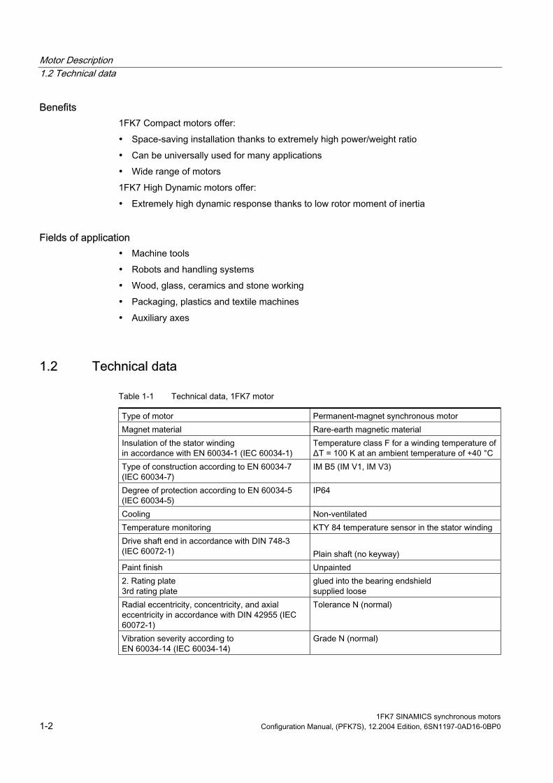
1.2 Technical data
Table 1-1 Technical data, 1FK7 motor
Type of motor Permanent-magnet synchronous motor Magnet material Rare-earth magnetic material Insulation of the stator winding Temperature class F for a winding temperature of
ΔT = 100 K at an ambient temperature of +40 °C Type of construction according to EN 60034-7 (IEC 60034-7)
IM B5 (IM V1, IM V3)
Degree of protection according to EN 60034-5 (IEC 60034-5)
IP64
Cooling Non-ventilated Temperature monitoring KTY 84 temperature sensor in the stator winding Drive shaft end in accordance with DIN 748-3 (IEC 60072-1)
Plain shaft (no keyway)
Paint finish Unpainted 2. Rating plate 3rd rating plate
glued into the bearing endshield supplied loose
Radial eccentricity, concentricity, and axial
60072-1)
Tolerance N (normal)
Vibration severity according to EN 60034-14 (IEC 60034-14)
Grade N (normal)
in accordance with EN 60034-1 (IEC 60034-1)
eccentricity in accordance with DIN 42955 (IEC
1FK7 SINAMICS synchronous motors 1-2 Configuration Manual, (PFK7S), 12.2004 Edition, 6SN1197-0AD16-0BP0

Motor Description 1.2 Technical data
Sound pressure level, max. acc. to DIN EN ISO 1680
1FK702: 55 dB (A) 1FK703: 55 dB (A) 1FK704: 55 dB (A) 1FK706: 65 dB (A) 1FK708: 70 dB (A) 1FK710: 70 dB (A)
Encoder systems, integrated for motors with/without DRIVE-CLiQ interface
• Incremental encoder sin/cos 1 Vpp 2048 pulses/revolution
• Absolute encoder 2), multiturn, K704 to
1FK710. 512 pulses/revolution with 1FK702 and 1FK703 and traversing range 4096 rev. with EnDat interface
• Simple absolute encoder 2), multiturn, 32 S/R and traversing range 4096 rev.with EnDat interface
• Resolver multi-pole 1) (number of poles corresponds to number of pole pairs of the motor)
• Resolver 2-pole Connection Connectors for signals and power
can be rotated (270°) Options • Drive shaft end with fitted key and keyway
(half-key balancing) • Integrated holding brake • Degree of protection IP65, additional IP67
drive end flange • Planetary gear unit (requires: plain shaft end
(no keyway) • Paint finish, anthracite
2048 pulses/revolution with 1F
1) For SINAMICS the max. operating frequency is 470 Hz - and this must be carefully observed. 2) When using an absolute value encoder the rated torque is reduced by 10%
1FK7 SINAMICS synchronous motors Configuration Manual, (PFK7S), 12.2004 Edition, 6SN1197-0AD16-0BP0 1-3

Motor Description 1.3 Order designation
1.3 Order designation
1.3.1 1FK7 Compact motors - core type, non-ventilated
Selection/Ordering data
7 7 7
7 7 7
7 7 7
7 7 7
7 7 7
7 7 7
7 7 7
7 7 7
7 7 7
7 7 7
7 7 7
7 7 7
7 7 7
7 7 7
7 7 7
7 7 7
7 7 7
7 7 7
1FK7 SINAMICS synchronous motors 1-4 Configuration Manual, (PFK7S), 12.2004 Edition, 6SN1197-0AD16-0BP0

Motor Description 1.3 Order designation
Selection/Ordering data
7
7
7
7
7
7
7
7
7
7
7
7
7
7
7
7
7
7 7 7 7 7
7 7 7 7
7 7 7 7
7 7 7 7
7 7 7 7
7 7 7 7
7 7 7 7
7 7 7 7
7 7 7 7
7 7 7 7
7 7 7 7
7 7 7 7
7 7 7 7
7 7 7 7
7 7 7 7
7 7 7 7
7 7 7 7
7 7 7 7
1FK7 SINAMICS synchronous motors Configuration Manual, (PFK7S), 12.2004 Edition, 6SN1197-0AD16-0BP0 1-5

Motor Description 1.3 Order designation
1.3.2 1FK7 High Dynamic motors - core type, non-ventilated
Selection/Ordering data
7 7 7
7 7 77 7 7
7 7 77 7 7
7 7 77 7 7
7 7 77 7 7
7 7 7
7 7 7
1FK7 SINAMICS synchronous motors 1-6 Configuration Manual, (PFK7S), 12.2004 Edition, 6SN1197-0AD16-0BP0

Motor Description 1.3 Order designation
Selection/Ordering data
7
7
7
7
7
7
7
7
7
7
7 7
7
7
7
7
7
7
7
7
7
7
7 7 7
7 7 7
7 7 7
7 7 7
7 7 7
7 7 7
7 7 7
7 7 7
7 7 7
7 7 7
7 7 7
1FK7 SINAMICS synchronous motors Configuration Manual, (PFK7S), 12.2004 Edition, 6SN1197-0AD16-0BP0 1-7

Motor Description 1.4 Armature short-circuit braking
1.4 Armature short-circuit braking The function description of armature short-circuit braking is described in the documentation "General Section for Synchronous Motors".
Dimensioning the braking resistors for optimum short-circuit braking The correct dimensioning ensures an optimum braking time. The braking torques which are obtained are also listed in the tables. Data apply for braking from the rated speed and moment of inertia Jexternal = Jmot If the drive is braked from another speed, then the braking time cannot be proportionally reduced. However, longer braking times cannot occur if the speed at the start of braking is less than the rated speed.
The data in the following table is calculated for rated values according to the data sheet. The variance during production as well as iron saturation have not been taken into account here. Higher currents and torques can occur than those calculated as a result of the saturation.
The ratings of the resistors must match the particular I2t load capability, refer to the Configuration Manual "General Section for Synchronous Motors".
1FK7 SINAMICS synchronous motors 1-8 Configuration Manual, (PFK7S), 12.2004 Edition, 6SN1197-0AD16-0BP0

Motor Description 1.4 Armature short-circuit braking
Table 1-2 Resistor braking for 1FK7 CT and 1FK7 HD
Average braking torque Mbr rms [Nm]
rms braking current Ibr rms [A]
Motor type Braking resistor external Ropt [Ω]
without external braking resistor
with external braking resistor
Max. braking torque Mbr max [Nm]
without external braking resistor
with external braking resistor
1FK7 CT 1FK7022-5AK71 1.0 1.8 1.9 2.3 9.0 8.7 1FK7032-5AK71 12.2 1.0 1.3 1.7 4.4 4.0 1FK7040-5AK71 18.1 0.5 1.0 1.2 3.5 3.1 1FK7042-5AF71 13.1 1.7 2.5 3.1 4.2 3.8 1FK7042-5AK71 7.2 1.2 2.7 3.3 9.0 8.1 1FK7060-5AF71 7.8 2, 2 4.5 5.5 7.9 7.1 1FK7060-5AH71 5.9 1.9 4.8 6.0 11.9 10.7 1FK7063-5AF71 4.2 4.1 9.1 11.3 15.6 14.0 1FK7063-5AH71 2.7 3.5 9.6 12.0 25.0 22.3 1FK7080-5AF71 7.8 2.9 6.9 8.6 10.1 9.0 1FK7080-5AH71 5.5 2.0 6.7 8.4 14.9 13.3 1FK7083-5AF71 3.4 5.6 14.4 17.9 22.3 19.9 1FK7083-5AH71 2.6 3.8 14.2 17.6 31.8 28.5 1FK7100-5AF71 4.1 4.2 13.4 16.6 19.9 17.8 1FK7101-5AF71 1.7 7.9 24.8 30.8 41.3 37.0 1FK7103-5AF71 1.2 10.1 33.9 42.2 59.2 53.0 1FK7105-5AC71 1.7 16.8 47.5 59.1 47.3 42.3 1FK7105-5AF71 1.1 12.9 48.3 60.0 72.5 64.9 1FK7 HD 1FK7033–7AK71 13.4 0.6 1.1 1.4 4.1 3.7 1FK7043–7AH71 9.4 0.7 1.7 2.1 5.5 4.9 1FK7043–7AK71 7.8 0.4 1.3 1.7 6.4 5.8 1FK7044–7AF71 7.9 1.0 2.0 2.5 5.2 4.7 1FK7044–7AH71 7.0 0.8 2.0 2.4 7.0 6.3 1FK7061–7AF71 8.7 0.9 3.0 3.7 6.4 5.8 1FK7061–7AH71 6.4 0.7 3.1 3.8 9.4 8.4 1FK7064–7AF71 4.7 1.6 5.6 7.0 12.0 10.8 1FK7064–7AH71 3.8 1.2 5.7 7.1 16.7 15.0 1FK7082–7AF71 5.9 2.0 7.1 8.8 12.1 10.8 1FK7085–7AF71 2.0 2.8 11.0 13.7 26.3 23.5
1FK7 SINAMICS synchronous motors Configuration Manual, (PFK7S), 12.2004 Edition, 6SN1197-0AD16-0BP0 1-9

Motor Description 1.5 Coupling output
1FK7 SINAMICS synchronous motors 1-10 Configuration Manual, (PFK7S), 12.2004 Edition, 6SN1197-0AD16-0BP0
1.5 Coupling output For a description and ordering address refer to the documentation "General Section for Synchronous Motors" or Internet www.ktr.com
Table 1-3 Assignment of the coupling outputs to the motors
Shaft height of the 1 FK7 motors
dw [mm]1) Rotex GS Type
Torques that can be transmitted
80 or 92 Sh–A–GS
pinion
TR [Nm] 4)
TKN [Nm]2) TKmax [Nm]3) 1FK7022–... 9 9 1.8 3.6 2.6 1FK7032–... 14 14 7.5 15 102 1FK704⃞–... 19 19/24 10 20 - 1FK706⃞–... 24 24/28 35 70 - 1FK708⃞–... 32 28/38 95 190 - 1FK710⃞–... 38 38/45 190 380 -
1)dw = diameter, motor shaft end 2)TKN = rated coupling torque 3)TKmax = maximum coupling torque 4) TR = friction-locked torque (torque that can be transmitted using a clamping hub at dw)
It may be necessary to use other annular gears (e.g. Shore hardness 80 Sh–A). They must be optimally harmonized with the mounted mechanical system.
Warning
The accelerating torque may not exceed the clamping torque of the coupling!
Notice
We cannot accept any liability for the quality and properties/features of third-party products.
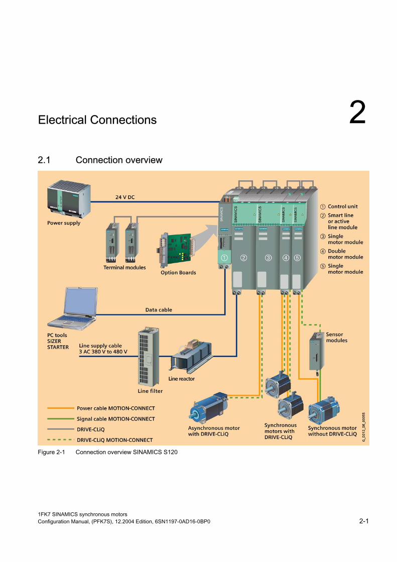
Electrical Connections 2 2.1 Connection overview
Figure 2-1 Connection overview SINAMICS S120
1FK7 SINAMICS synchronous motors Configuration Manual, (PFK7S), 12.2004 Edition, 6SN1197-0AD16-0BP0 2-1
Electrical Connections 2.2 Power connection
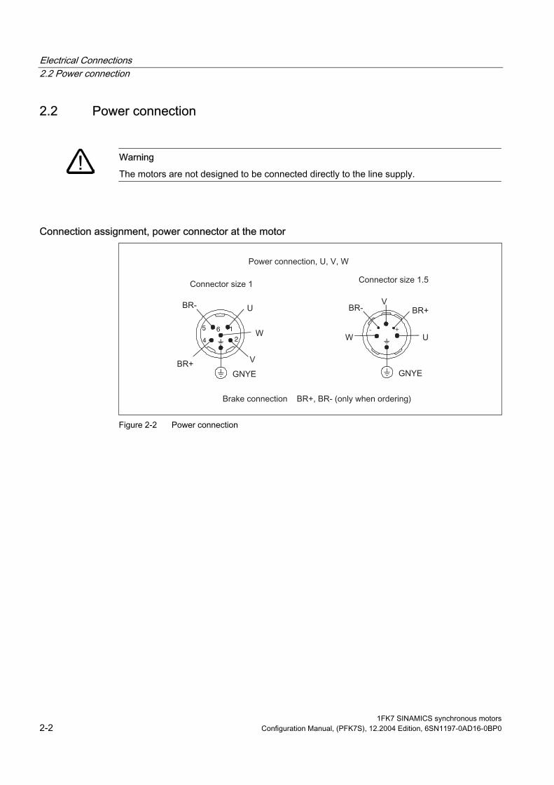
2.2 Power connection
Warning
The motors are not designed to be connected directly to the line supply.
Connection assignment, power connector at the motor
1
24
5 6 - +
Figure 2-2 Power connection
1FK7 SINAMICS synchronous motors 2-2 Configuration Manual, (PFK7S), 12.2004 Edition, 6SN1197-0AD16-0BP0

Electrical Connections 2.3 DRIVE-CLiQ
2.3 DRIVE-CLiQ The encoder system can only be connected to SINAMICS S120 via DRIVE-CLiQ.
The DRIVE-CLiQ interface is either established through the sensor module at the motor (motors with DRIVE-CLiQ) or in the cabinet using sensor module, cabinet-mounted (for motors without DRIVE-CLiQ).
2.4 Motors with DRIVE-CLiQ Motors with DRIVE-CLiQ have a sensor module that includes the encoder evaluation, the motor temperature sensing as well as an electronic rating plate with a unique identification number and motor and encoder-specific data.
These motors with DRIVE-CLiQ can be connected to the corresponding motor module directly via the MOTION-CONNECT DRIVE-CLiQ cables supplied. This means that data is directly transferred to the control unit.
These motors make start-up and diagnostics much easier, as the motor and encoder type can be identified automatically.
Figure 2-3 Connecting encoders for motors with DRIVE-CLiQ
1FK7 SINAMICS synchronous motors Configuration Manual, (PFK7S), 12.2004 Edition, 6SN1197-0AD16-0BP0 2-3

Electrical Connections 2.5 Motors without DRIVE-CLiQ
2.5 Motors without DRIVE-CLiQ When fed from SINAMICS S120, motors without DRIVE-CLiQ require a sensor module, cabinet-mounted. The sensor modules evaluate the signals from the connected motor sensors or external sensors and convert them to DRIVE-CLiQ. In conjunction with motor encoders, the motor temperature can also be evaluated using sensor modules. Additional information is provided in the SINAMICS Equipment Manual.
Figure 2-4 Connecting encoders without DRIVE-CLiQ
2.6 Rotating the connector at the motor Power connector, signal connector and DRIVE-CLiQ can, to some extent, be rotated.
Notice
The permissible range of rotation may not be exceeded. ay be rotated a max. of 10x
up to its end stop. Do not exceed the max. torque when rotating.
ed at the connector thread. Connecting cables must be secured against tensile stress and bending. The motor connectors must be secured so that they cannot be rotated any further. It is not permissible to permanently subject connectors to forces.
In order to guarantee the degree of protection, the connector m
The connector should be rotated using a mating connector attach
1FK7 SINAMICS synchronous motors 2-4 Configuration Manual, (PFK7S), 12.2004 Edition, 6SN1197-0AD16-0BP0
Electrical Connections 2.6 Rotating the connector at the motor
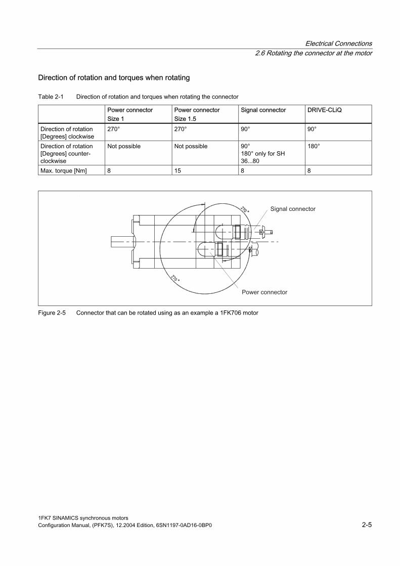
Direction of rotation and torques when rotating
Table 2-1 Direction of rotation and torques when rotating the connector
Power connector Size 1
Power connector Size 1.5
Signal connector DRIVE-CLiQ
Direction of rotation [Degrees] clockwise
270° 270° 90° 90°
Direction of rotation [Degrees] counter-clockwise
Not possible Not possible 90° 180° only for SH 36...80
180°
Max. torque [Nm] 8 15 8 8
Figure 2-5 Connector that can be rotated using as an example a 1FK706 motor
1FK7 SINAMICS synchronous motors Configuration Manual, (PFK7S), 12.2004 Edition, 6SN1197-0AD16-0BP0 2-5
Electrical Connections 2.6 Rotating the connector at the motor
1FK7 SINAMICS synchronous motors 2-6 Configuration Manual, (PFK7S), 12.2004 Edition, 6SN1197-0AD16-0BP0

Technical Data and Speed-Torque Diagrams 3 3.1 Introduction
Note
For converter operation on a 480 V line supply, DC link voltages occur which are greater than 600 V. The motors are suitable for DC link voltages up to 740 V.
Refer to the Documentation "General Section for Synchronous Motors" for a description of how the voltage limiting characteristics are shifted.
The specified thermal S3 limiting characteristics are referred to ΔT = 100 K for
- 1 min cycle duration for SH 28 and 36
- 10 min cycle duration for SH 48, 63, 80, 100, 132, 160
1FK7 SINAMICS synchronous motors Configuration Manual, (PFK7S), 12.2004 Edition, 6SN1197-0AD16-0BP0 3-1
Technical Data and Speed-Torque Diagrams 3.2 Speed-torque diagrams 1FK7 CT
3.2 Speed-torque diagrams 1FK7 CT
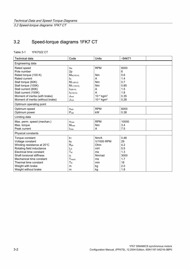
Table 3-1 1FK7022 CT
Technical data Code Units –5AK71 Engineering data Rated speed Pole number Rated torque (100 K) Rated current Stall torque (60K) Stall torque (100K) Stall current (60K) Stall current (100K) Moment of inertia (with brake) Moment of inertia (without brake)
nN 2p MN(100 K) IN M0 (60 K) M0 (100 K) I0(60 K) I0(100 K) Jmot Jmot
RPM Nm A Nm Nm A A 10–4 kgm2 10–4 kgm2
6000 6 0.6 1.4 0.7 0.85 1.5 1.8 0.35 0.28
Optimum operating point Optimum speed Optimum power
nopt Popt
RPM kW
6000 0.38
Limiting data Max. perm. speed (mechan.) Max. torque Peak current
nmax Mmax Imax
RPM Nm A
10000 3.4 7.5
Physical constants Torque constant Voltage constant
Rotating field inductance Electrical time constant Shaft torsional stiffness Mechanical time constant
Weight with brake Weight without brake
kT kE Rph LD Tel ct Tmech Tth m m
Nm/A V/1000 RPM Ohm mH ms Nm/rad ms min kg kg
0.46 29 4.2 5.5 1.3 3000 1.7 18 2.0 1.8
Winding resistance at 20°C
Thermal time constant
1FK7 SINAMICS synchronous motors 3-2 Configuration Manual, (PFK7S), 12.2004 Edition, 6SN1197-0AD16-0BP0

Technical Data and Speed-Torque Diagrams 3.2 Speed-torque diagrams 1FK7 CT
Figure 3-1 Speed-torque diagram 1FK7022-5AK71 CT
[a] SINAMICS S120 SMART LINE VDC link=540V (DC), Vmot=380Vrms [b] SINAMICS S120 ACTIVE LINE VDC link =600V (DC), Vmot=425V rms
1FK7 SINAMICS synchronous motors Configuration Manual, (PFK7S), 12.2004 Edition, 6SN1197-0AD16-0BP0 3-3

Technical Data and Speed-Torque Diagrams 3.2 Speed-torque diagrams 1FK7 CT
Table 3-2 1FK7032 CT
Technical data Code Units –5AK71 Engineering data Rated speed Pole number Rated torque (100 K) Rated current Stall torque (60K) Stall torque (100K) Stall current (60K) Stall current (100K) Moment of inertia (with brake) Moment of inertia (without brake)
nN 2p MN(100 K) IN M0 (60 K) M0 (100 K) I0(60 K) I0(100 K) Jmot Jmot
RPM Nm A Nm Nm A A 10–4 kgm2 10–4 kgm2
6000 6 0.8 1.4 0.85 1.1 1.4 1.7 0.69 0.61
Optimum operating point Optimum speed Optimum power
nopt Popt
RPM kW
6000 0.5
Limiting data Max. perm. speed (mechan.) Max. torque Peak current
nmax Mmax Imax
RPM Nm A
10000 4.5 7.5
Physical constants Torque constant Voltage constant
Rotating field inductance Electrical time constant Shaft torsional stiffness Mechanical time constant
Weight with brake Weight without brake
kT kE Rph LD Tel ct Tmech Tth m m
Nm/A V/1000 RPM Ohm mH ms Nm/rad ms min kg kg
0.66 42 5.2 18.5 3.6 6500 2.2 25 3.0 2.7
Winding resistance at 20°C
Thermal time constant
1FK7 SINAMICS synchronous motors 3-4 Configuration Manual, (PFK7S), 12.2004 Edition, 6SN1197-0AD16-0BP0
Technical Data and Speed-Torque Diagrams 3.2 Speed-torque diagrams 1FK7 CT
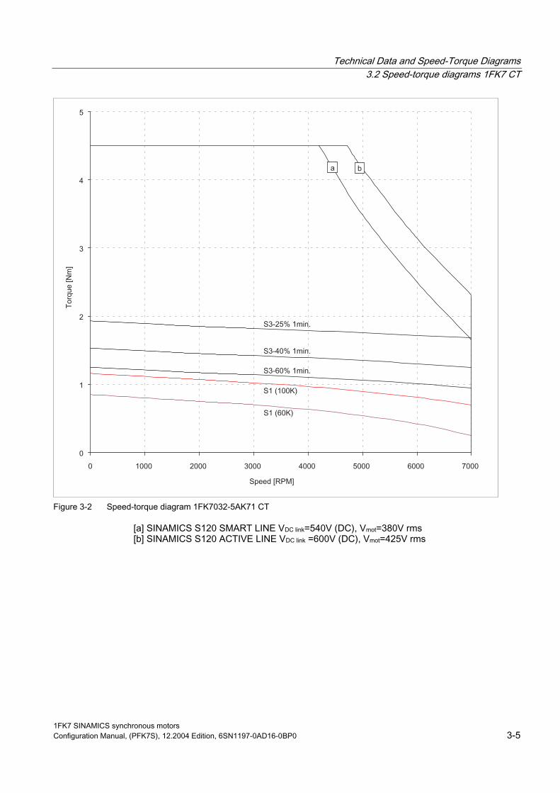
Figure 3-2 Speed-torque diagram 1FK7032-5AK71 CT
[a] SINAMICS S120 SMART LINE VDC link=540V (DC), Vmot=380V rms [b] SINAMICS S120 ACTIVE LINE VDC link =600V (DC), Vmot=425V rms
1FK7 SINAMICS synchronous motors Configuration Manual, (PFK7S), 12.2004 Edition, 6SN1197-0AD16-0BP0 3-5

Technical Data and Speed-Torque Diagrams 3.2 Speed-torque diagrams 1FK7 CT
Table 3-3 1FK7040 CT
Technical data Code Units –5AK71 Engineering data Rated speed Pole number Rated torque (100 K) Rated current Stall torque (60K) Stall torque (100K) Stall current (60K) Stall current (100K) Moment of inertia (with brake) Moment of inertia (without brake)
nN 2p MN(100 K) IN M0 (60 K) M0 (100 K) I0(60 K) I0(100 K) Jmot Jmot
RPM Nm A Nm Nm A A 10–4 kgm2 10–4 kgm2
6000 8 1.1 1.7 1.3 1.6 1.8 2.25 2.41 1.69
Optimum operating point Optimum speed Optimum power
nopt Popt
RPM kW
6000 0.69
Limiting data Max. perm. speed (mechan.) Max. torque Peak current
nmax Mmax Imax
RPM Nm A
9000 5.1 7.7
Physical constants Torque constant Voltage constant
Rotating field inductance Electrical time constant Shaft torsional stiffness Mechanical time constant
Weight with brake Weight without brake
kT kE Rph LD Tel ct Tmech Tth m m
Nm/A V/1000 RPM Ohm mH ms Nm/rad ms min kg kg
0.68 43 3.3 17 5.15 19000 3.62 25 4.0 3.5
Winding resistance at 20°C
Thermal time constant
1FK7 SINAMICS synchronous motors 3-6 Configuration Manual, (PFK7S), 12.2004 Edition, 6SN1197-0AD16-0BP0
Technical Data and Speed-Torque Diagrams 3.2 Speed-torque diagrams 1FK7 CT
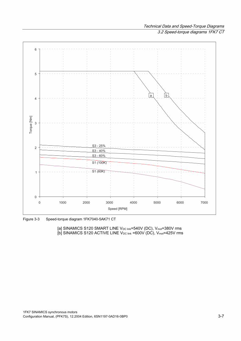
Figure 3-3 Speed-torque diagram 1FK7040-5AK71 CT
[a] SINAMICS S120 SMART LINE VDC link=540V (DC), Vmot=380V rms [b] SINAMICS S120 ACTIVE LINE VDC link =600V (DC), Vmot=425V rms
1FK7 SINAMICS synchronous motors Configuration Manual, (PFK7S), 12.2004 Edition, 6SN1197-0AD16-0BP0 3-7
Technical Data and Speed-Torque Diagrams 3.2 Speed-torque diagrams 1FK7 CT
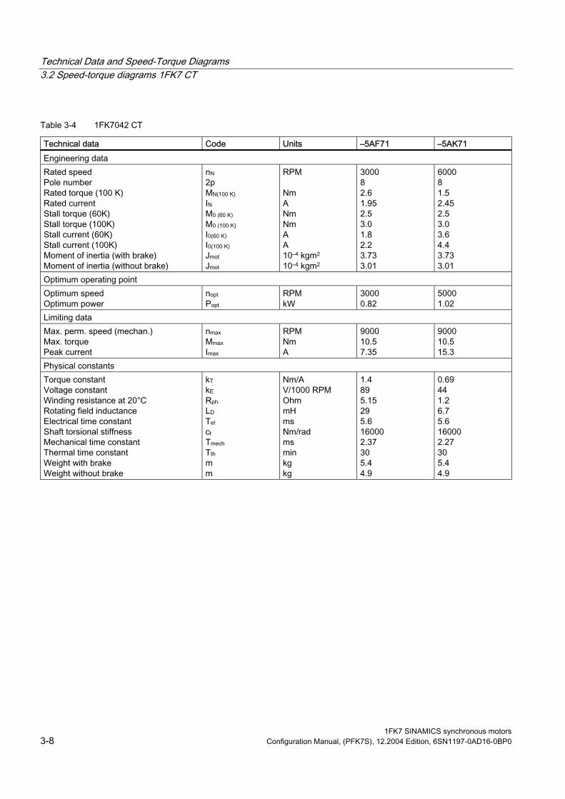
Table 3-4 1FK7042 CT
Technical data Code Units –5AF71 –5AK71 Engineering data Rated speed Pole number Rated torque (100 K) Rated current Stall torque (60K) Stall torque (100K) Stall current (60K) Stall current (100K) Moment of inertia (with brake) Moment of inertia (without brake)
nN 2p MN(100 K) IN M0 (60 K) M0 (100 K) I0(60 K) I0(100 K) Jmot Jmot
RPM Nm A Nm Nm A A 10–4 kgm2 10–4 kgm2
3000 8 2.6 1.95 2.5 3.0 1.8 2.2 3.73 3.01
6000 8 1.5 2.45 2.5 3.0 3.6 4.4 3.73 3.01
Optimum operating point Optimum speed Optimum power
nopt Popt
RPM kW
3000 0.82
5000 1.02
Limiting data Max. perm. speed (mechan.) Max. torque Peak current
nmax Mmax Imax
RPM Nm A
9000 10.5 7.35
9000 10.5 15.3
Physical constants Torque constant Voltage constant
Rotating field inductance Electrical time constant Shaft torsional stiffness Mechanical time constant
Weight with brake Weight without brake
kT kE Rph LD Tel ct Tmech Tth m m
Nm/A V/1000 RPM Ohm mH ms Nm/rad ms min kg kg
1.4 89 5.15 29 5.6 16000 2.37 30 5.4 4.9
0.69 44 1.2 6.7 5.6 16000 2.27 30 5.4 4.9
Winding resistance at 20°C
Thermal time constant
1FK7 SINAMICS synchronous motors 3-8 Configuration Manual, (PFK7S), 12.2004 Edition, 6SN1197-0AD16-0BP0

Technical Data and Speed-Torque Diagrams 3.2 Speed-torque diagrams 1FK7 CT
Figure 3-4 Speed-torque diagram 1FK7042-5AF71 CT
Figure 3-5 Speed-torque diagram 1FK7042-5AK71 CT
[a] SINAMICS S120 SMART LINE VDC link=540V (DC), Vmot=380V rms [b] SINAMICS S120 ACTIVE LINE VDC link =600V (DC), Vmot=425V rms
1FK7 SINAMICS synchronous motors Configuration Manual, (PFK7S), 12.2004 Edition, 6SN1197-0AD16-0BP0 3-9

Technical Data and Speed-Torque Diagrams 3.2 Speed-torque diagrams 1FK7 CT
Table 3-5 1FK7060 CT
Technical data Code Units –5AF71 –5AH71 Engineering data Rated speed Pole number Rated torque (100 K) Rated current Stall torque (60K) Stall torque (100K) Stall current (60K) Stall current (100K) Moment of inertia (with brake) Moment of inertia (without brake)
nN 2p MN(100 K) IN M0 (60 K) M0 (100 K) I0(60 K) I0(100 K) Jmot Jmot
RPM Nm A Nm Nm A A 10–4 kgm2 10–4 kgm2
3000 8 4.7 3.7 5.0 6.0 3.7 4.5 10.2 7.95
4500 8 3.7 4.1 5.0 6.0 5.1 6.2 10.2 7.95
Optimum operating point Optimum speed Optimum power
nopt Popt
RPM kW
3000 1.48
4500 1.74
Limiting data Max. perm. speed (mechan.) Max. torque Peak current
nmax Mmax Imax
RPM Nm A
7200 18 15
7200 18 19.5
Physical constants Torque constant Voltage constant
Rotating field inductance Electrical time constant Shaft torsional stiffness Mechanical time constant
Weight with brake Weight without brake
kT kE Rph LD Tel ct Tmech Tth m m
Nm/A V/1000 RPM Ohm mH ms Nm/rad ms min kg kg
1.33 84.5 1.44 14.7 10.2 42000 1.94 30 8 7
0.95 60.5 0.73 7.0 9.6 42000 1.93 30 8 7
Winding resistance at 20°C
Thermal time constant
1FK7 SINAMICS synchronous motors 3-10 Configuration Manual, (PFK7S), 12.2004 Edition, 6SN1197-0AD16-0BP0
Technical Data and Speed-Torque Diagrams 3.2 Speed-torque diagrams 1FK7 CT
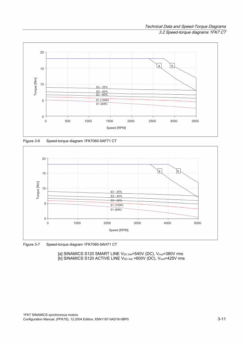
Figure 3-6 Speed-torque diagram 1FK7060-5AF71 CT
Figure 3-7 Speed-torque diagram 1FK7060-5AH71 CT
[a] SINAMICS S120 SMART LINE VDC link=540V (DC), Vmot=380V rms [b] SINAMICS S120 ACTIVE LINE VDC link =600V (DC), Vmot=425V rms
1FK7 SINAMICS synchronous motors Configuration Manual, (PFK7S), 12.2004 Edition, 6SN1197-0AD16-0BP0 3-11

Technical Data and Speed-Torque Diagrams 3.2 Speed-torque diagrams 1FK7 CT
Table 3-6 1FK7063 CT
Technical data Code Units –5AF71 –5AH71 Engineering data Rated speed Pole number Rated torque (100 K) Rated current Stall torque (60K) Stall torque (100K) Stall current (60K) Stall current (100K) Moment of inertia (with brake) Moment of inertia (without brake)
nN 2p MN(100 K) IN M0 (60 K) M0 (100 K) I0(60 K) I0(100 K) Jmot Jmot
RPM Nm A Nm Nm A A 10–4 kgm2 10–4 kgm2
3000 8 7.3 5.6 9.1 11 6.6 8.0 17.3 15.1
4500 8 3 3.8 9.1 11 9.9 12.0 17.3 15.1
Optimum operating point Optimum speed Optimum power
nopt Popt
RPM kW
3000 2.29
3300 2.32
Limiting data Max. perm. speed (mechan.) Max. torque Peak current
nmax Mmax Imax
RPM Nm A
7200 35 28
7200 35 42
Physical constants Torque constant Voltage constant
Rotating field inductance Electrical time constant Shaft torsional stiffness Mechanical time constant
Weight with brake Weight without brake
kT kE Rph LD Tel ct Tmech Tth m m
Nm/A V/1000 RPM Ohm mH ms Nm/rad ms min kg kg
1.37 87.5 0.65 7.7 11.8 35000 1.56 40 12 11.5
0.91 58 0.29 3.2 11 35000 1.58 40 12 11.5
Winding resistance at 20°C
Thermal time constant
1FK7 SINAMICS synchronous motors 3-12 Configuration Manual, (PFK7S), 12.2004 Edition, 6SN1197-0AD16-0BP0

Technical Data and Speed-Torque Diagrams 3.2 Speed-torque diagrams 1FK7 CT
Figure 3-8 Speed-torque diagram 1FK7063-5AF71 CT
Figure 3-9 Speed-torque diagram 1FK7063-5AH71 CT
[a] SINAMICS S120 SMART LINE VDC link=540V (DC), Vmot=380V rms [b] SINAMICS S120 ACTIVE LINE VDC link =600V (DC), Vmot=425V rms
1FK7 SINAMICS synchronous motors Configuration Manual, (PFK7S), 12.2004 Edition, 6SN1197-0AD16-0BP0 3-13

Technical Data and Speed-Torque Diagrams 3.2 Speed-torque diagrams 1FK7 CT
Table 3-7 1FK7080 CT
Technical data Code Units –5AF71 –5AH71 Engineering data Rated speed Pole number Rated torque (100 K) Rated current Stall torque (60K) Stall torque (100K) Stall current (60K) Stall current (100K) Moment of inertia (with brake) Moment of inertia (without brake)
nN 2p MN(100 K) IN M0 (60 K) M0 (100 K) I0(60 K) I0(100 K) Jmot Jmot
RPM Nm A Nm Nm A A 10–4 kgm2 10–4 kgm2
3000 8 6.8 4.4 6.6 8 4 4.8 18.1 15
4500 8 4.5 4.7 6.6 8 6.1 7.4 18.1 15
Optimum operating point Optimum speed Optimum power
nopt Popt
RPM kW
3000 2.14
4000 2.39
Limiting data Max. perm. speed (mechan.) Max. torque Peak current
nmax Mmax Imax
RPM Nm A
6000 25 18
6000 25 25
Physical constants Torque constant Voltage constant
Rotating field inductance Electrical time constant Shaft torsional stiffness Mechanical time constant
Weight with brake Weight without brake
kT kE Rph LD Tel ct Tmech Tth m m
Nm/A V/1000 RPM Ohm mH ms Nm/rad ms min kg kg
1.61 102.5 1.04 14.0 13.5 126000 1.78 40 12.5 10
1.06 68.0 0.44 6.3 14.3 126000 1.76 40 12.5 10
Winding resistance at 20°C
Thermal time constant
1FK7 SINAMICS synchronous motors 3-14 Configuration Manual, (PFK7S), 12.2004 Edition, 6SN1197-0AD16-0BP0
Technical Data and Speed-Torque Diagrams 3.2 Speed-torque diagrams 1FK7 CT
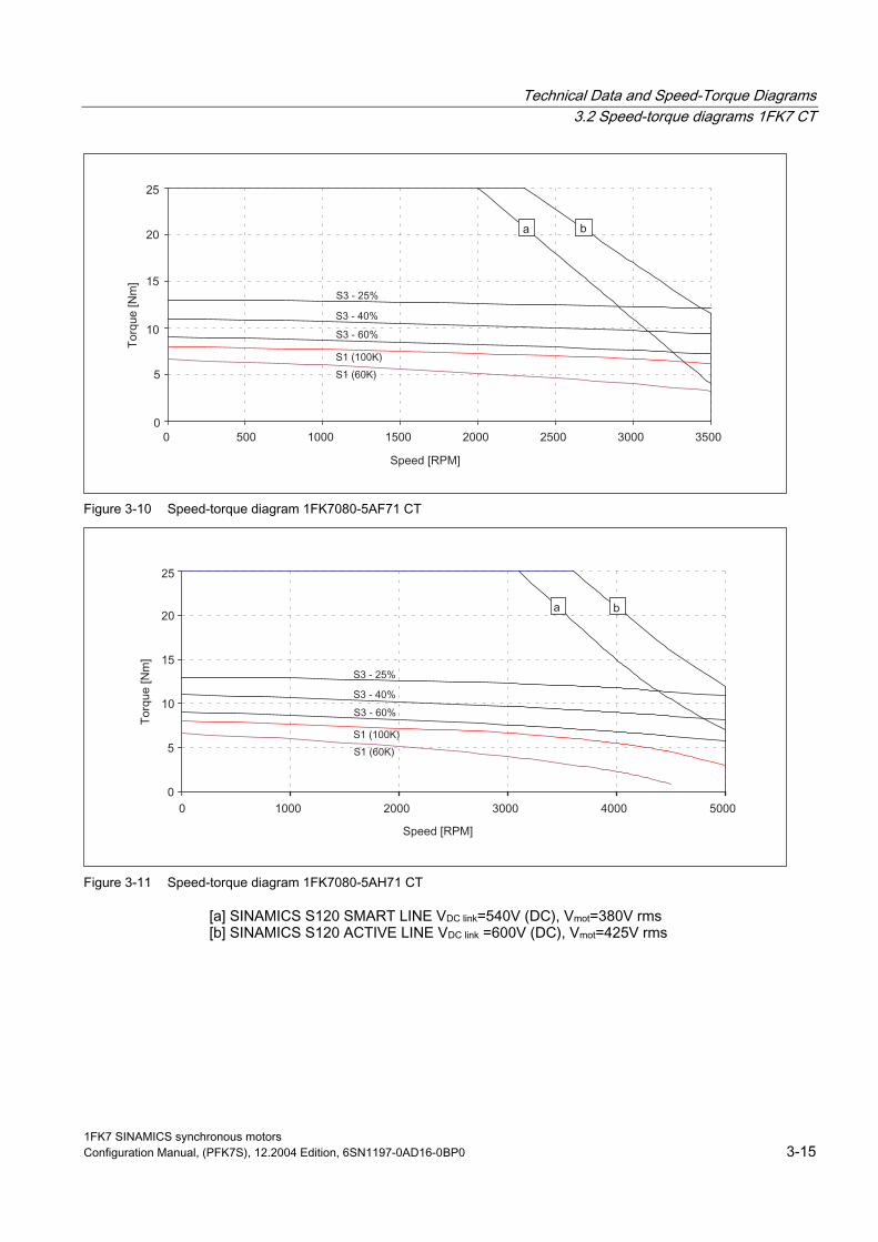
Figure 3-10 Speed-torque diagram 1FK7080-5AF71 CT
Figure 3-11 Speed-torque diagram 1FK7080-5AH71 CT
[a] SINAMICS S120 SMART LINE VDC link=540V (DC), Vmot=380V rms [b] SINAMICS S120 ACTIVE LINE VDC link =600V (DC), Vmot=425V rms
1FK7 SINAMICS synchronous motors Configuration Manual, (PFK7S), 12.2004 Edition, 6SN1197-0AD16-0BP0 3-15

Technical Data and Speed-Torque Diagrams 3.2 Speed-torque diagrams 1FK7 CT
Table 3-8 1FK7083 CT
Technical data Code Units –5AF71 –5AH71 Engineering data Rated speed Pole number Rated torque (100 K) Rated current Stall torque (60K) Stall torque (100K) Stall current (60K) Stall current (100K) Moment of inertia (with brake) Moment of inertia (without brake)
nN 2p MN(100 K) IN M0 (60 K) M0 (100 K) I0(60 K) I0(100 K) Jmot Jmot
RPM Nm A Nm Nm A A 10–4 kgm2 10–4 kgm2
3000 8 10.5 7.4 13.3 16 8.6 10.4 35.9 27.3
4500 8 3 3.6 13.3 16 12.4 15 35.9 27.3
Optimum operating point Optimum speed Optimum power
nopt Popt
RPM kW
3000 3.3
3000 3.3
Limiting data Max. perm. speed (mechan.) Max. torque Peak current
nmax Mmax Imax
RPM Nm A
6000 50 37
6000 50 52
Physical constants Torque constant Voltage constant
Rotating field inductance Electrical time constant Shaft torsional stiffness Mechanical time constant
Weight with brake Weight without brake
kT kE Rph LD Tel ct Tmech Tth m m
Nm/A V/1000 RPM Ohm mH ms Nm/rad ms min kg kg
1.52 97 0.4 6.0 15 105000 1.41 50 16.5 14
1.05 67 0.17 2.9 17 105000 1.26 50 16.5 14
Winding resistance at 20°C
Thermal time constant
1FK7 SINAMICS synchronous motors 3-16 Configuration Manual, (PFK7S), 12.2004 Edition, 6SN1197-0AD16-0BP0

Technical Data and Speed-Torque Diagrams 3.2 Speed-torque diagrams 1FK7 CT
Figure 3-12 Speed-torque diagram 1FK7083-5AF71
Figure 3-13 Speed-torque diagram 1FK7083-5AH71 CT
[a] SINAMICS S120 SMART LINE VDC link=540V (DC), Vmot=380V rms [b] SINAMICS S120 ACTIVE LINE VDC link =600V (DC), Vmot=425V rms
1FK7 SINAMICS synchronous motors Configuration Manual, (PFK7S), 12.2004 Edition, 6SN1197-0AD16-0BP0 3-17

Technical Data and Speed-Torque Diagrams 3.2 Speed-torque diagrams 1FK7 CT
Table 3-9 1FK7100 CT
Technical data Code Units –5AF71 Engineering data Rated speed Pole number Rated torque (100 K) Rated current Stall torque (60K) Stall torque (100K) Stall current (60K) Stall current (100K) Moment of inertia (with brake) Moment of inertia (without brake)
nN 2p MN(100 K) IN M0 (60 K) M0 (100 K) I0(60 K) I0(100 K) Jmot Jmot
RPM Nm A Nm Nm A A 10–4 kgm2 10–4 kgm2
3000 8 12 8 15 18 9.2 11.2 63.9 55.3
Optimum operating point Optimum speed Optimum power
nopt Popt
RPM kW
3000 3.77
Limiting data Max. perm. speed (mechan.) Max. torque Peak current
nmax Mmax Imax
RPM Nm A
5000 55 37
Physical constants Torque constant Voltage constant
Rotating field inductance Electrical time constant Shaft torsional stiffness Mechanical time constant
Weight with brake Weight without brake
kT kE Rph LD Tel ct Tmech Tth m m
Nm/A V/1000 RPM Ohm mH ms Nm/rad ms min kg kg
1.59 101 0.34 7.0 20.5 184000 2.23 55 21.5 19
Winding resistance at 20°C
Thermal time constant
1FK7 SINAMICS synchronous motors 3-18 Configuration Manual, (PFK7S), 12.2004 Edition, 6SN1197-0AD16-0BP0
Technical Data and Speed-Torque Diagrams 3.2 Speed-torque diagrams 1FK7 CT
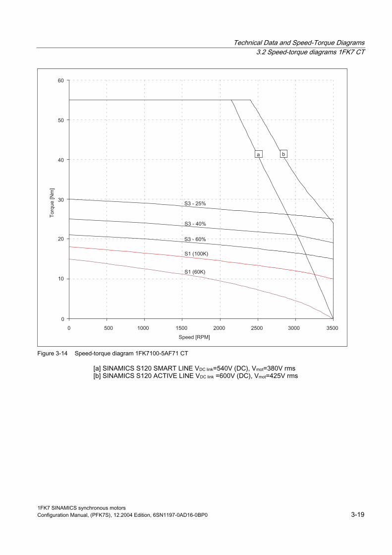
Figure 3-14 Speed-torque diagram 1FK7100-5AF71 CT
[a] SINAMICS S120 SMART LINE VDC link=540V (DC), Vmot=380V rms [b] SINAMICS S120 ACTIVE LINE VDC link =600V (DC), Vmot=425V rms
1FK7 SINAMICS synchronous motors Configuration Manual, (PFK7S), 12.2004 Edition, 6SN1197-0AD16-0BP0 3-19

Technical Data and Speed-Torque Diagrams 3.2 Speed-torque diagrams 1FK7 CT
Table 3-10 1FK7101 CT
Technical data Code Units –5AF71 Engineering data Rated speed Pole number Rated torque (100 K) Rated current Stall torque (60K) Stall torque (100K) Stall current (60K) Stall current (100K) Moment of inertia (with brake) Moment of inertia (without brake)
nN 2p MN(100 K) IN M0 (60 K) M0 (100 K) I0(60 K) I0(100 K) Jmot Jmot
RPM Nm A Nm Nm A A 10–4 kgm2 10–4 kgm2
3000 8 15.5 11.8 22.4 27 15.7 19 92.3 79.9
Optimum operating point Optimum speed Optimum power
nopt Popt
RPM kW
3000 4.87
Limiting data Max. perm. speed (mechan.) Max. torque Peak current
nmax Mmax Imax
RPM Nm A
5000 80 63
Physical constants Torque constant Voltage constant
Rotating field inductance Electrical time constant Shaft torsional stiffness Mechanical time constant
Weight with brake Weight without brake
kT kE Rph LD Tel ct Tmech Tth m m
Nm/A V/1000 RPM Ohm mH ms Nm/rad ms min kg kg
1.41 90 0.15 3.0 20 165000 1.80 60 24 21
Winding resistance at 20°C
Thermal time constant
1FK7 SINAMICS synchronous motors 3-20 Configuration Manual, (PFK7S), 12.2004 Edition, 6SN1197-0AD16-0BP0
Technical Data and Speed-Torque Diagrams 3.2 Speed-torque diagrams 1FK7 CT
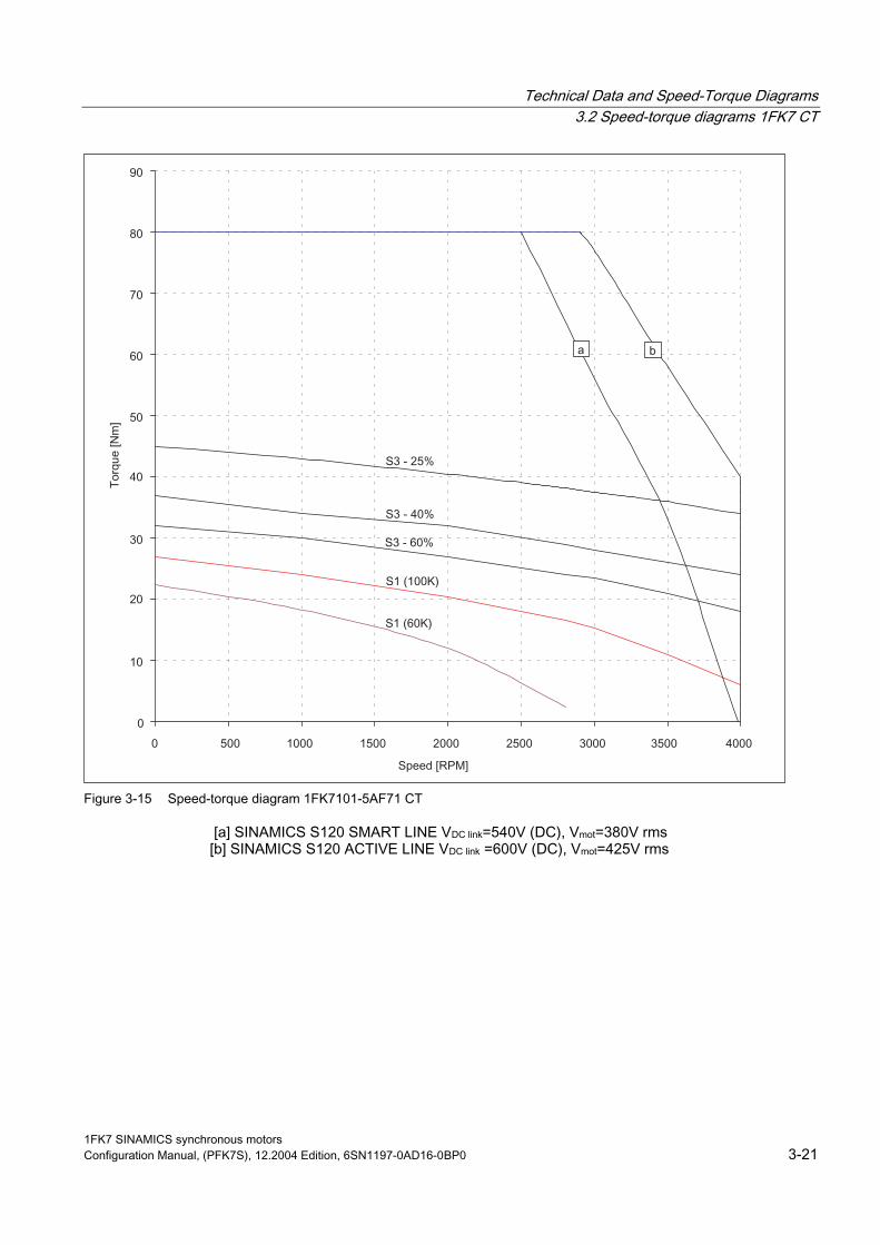
Figure 3-15 Speed-torque diagram 1FK7101-5AF71 CT
[a] SINAMICS S120 SMART LINE VDC link=540V (DC), Vmot=380V rms [b] SINAMICS S120 ACTIVE LINE VDC link =600V (DC), Vmot=425V rms
1FK7 SINAMICS synchronous motors Configuration Manual, (PFK7S), 12.2004 Edition, 6SN1197-0AD16-0BP0 3-21

Technical Data and Speed-Torque Diagrams 3.2 Speed-torque diagrams 1FK7 CT
Table 3-11 1FK7103 CT
Technical data Code Units –5AF71 Engineering data Rated speed Pole number Rated torque (100 K) Rated current Stall torque (60K) Stall torque (100K) Stall current (60K) Stall current (100K) Moment of inertia (with brake) Moment of inertia (without brake)
nN 2p MN(100 K) IN M0 (60 K) M0 (100 K) I0(60 K) I0(100 K) Jmot Jmot
RPM Nm A Nm Nm A A 10–4 kgm2 10–4 kgm2
3000 8 14 12 30 36 22.8 27.5 118 105
Optimum operating point Optimum speed Optimum power
nopt Popt
RPM kW
2500 5.37
Limiting data Max. perm. speed (mechan.) Max. torque Peak current
nmax Mmax Imax
RPM Nm A
5000 108 84
Physical constants Torque constant Voltage constant
Rotating field inductance Electrical time constant Shaft torsional stiffness Mechanical time constant
Weight with brake Weight without brake
kT kE Rph LD Tel ct Tmech Tth m m
Nm/A V/1000 RPM Ohm mH ms Nm/rad ms min kg kg
1.35 86 0.09 2.0 22.2 149000 1.55 65 32 29
Winding resistance at 20°C
Thermal time constant
1FK7 SINAMICS synchronous motors 3-22 Configuration Manual, (PFK7S), 12.2004 Edition, 6SN1197-0AD16-0BP0

Technical Data and Speed-Torque Diagrams 3.2 Speed-torque diagrams 1FK7 CT
Figure 3-16 Speed-torque diagram 1FK7103-5AF71 CT
[a] SINAMICS S120 SMART LINE VDC link=540V (DC), Vmot=380V rms [b] SINAMICS S120 ACTIVE LINE VDC link =600V (DC), Vmot=425V rms
1FK7 SINAMICS synchronous motors Configuration Manual, (PFK7S), 12.2004 Edition, 6SN1197-0AD16-0BP0 3-23

Technical Data and Speed-Torque Diagrams 3.2 Speed-torque diagrams 1FK7 CT
Table 3-12 1FK7105 CT
Technical data Code Units –5AC7 –5AF7 Engineering data Rated speed Pole number Rated torque (100 K) Rated current Stall torque (60K) Stall torque (100K) Stall current (60K) Stall current (100K) Moment of inertia (with brake) Moment of inertia (without brake)
nN 2p MN(100 K) IN M0 (60 K) M0 (100 K) I0(60 K) I0(100 K) Jmot Jmot
RPM Nm A Nm Nm A A 10–4 kgm2 10–4 kgm2
2000 8 37 16 40 48 17 20 169 156
3000 8 26 18 40 48 25 31 169 156
Optimum operating point Optimum speed Optimum power
nopt Popt
RPM kW
3000 8.17
3000 8.17
Limiting data Max. perm. speed (mechan.) Max. torque Peak current
nmax Mmax Imax
RPM Nm A
5000 150 72
5000 150 109
Physical constants Torque constant Voltage constant
Rotating field inductance Electrical time constant Shaft torsional stiffness Mechanical time constant
Weight with brake Weight without brake
kT kE Rph LD Tel ct Tmech Tth m m
Nm/A V/1000 RPM Ohm mH ms Nm/rad ms min kg kg
2.37 151 0.17 4.4 26 125000 14.2 70 41.5 39.1
1.57 100 0.074 1.9 26 125000 14.1 70 41.5 39.1
Winding resistance at 20°C
Thermal time constant
1FK7 SINAMICS synchronous motors 3-24 Configuration Manual, (PFK7S), 12.2004 Edition, 6SN1197-0AD16-0BP0

Technical Data and Speed-Torque Diagrams 3.2 Speed-torque diagrams 1FK7 CT
Figure 3-17 Speed-torque diagram 1FK7105-5AC7 CT
Figure 3-18 Speed-torque diagram 1FK7105-5AC7 CT
[a] SINAMICS S120 SMART LINE VDC link=540V (DC), Vmot=380V rms [b] SINAMICS S120 ACTIVE LINE VDC link =600V (DC), Vmot=425V rms
1FK7 SINAMICS synchronous motors Configuration Manual, (PFK7S), 12.2004 Edition, 6SN1197-0AD16-0BP0 3-25

Technical Data and Speed-Torque Diagrams 3.3 Speed-torque diagrams 1FK7 HD
3.3 Speed-torque diagrams 1FK7 HD
Table 3-13 1FK7033 HD
Technical data Code Units –7AK71 Engineering data Rated speed Pole number Rated torque (100 K) Rated current Stall torque (60K) Stall torque (100K) Stall current (60K) Stall current (100K) Moment of inertia (with brake) Moment of inertia (without brake)
nN 2p MN(100 K) IN M0 (60 K) M0 (100 K) I0(60 K) I0(100 K) Jmot Jmot
RPM Nm A Nm Nm A A 10–4 kgm2 10–4 kgm2
6000 6 0.9 1.5 1.0 1.3 1.7 2.2 0.3 0.27
Optimum operating point Optimum speed Optimum power
nopt Popt
RPM kW
6000 0.56
Limiting data Max. perm. speed (mechan.) Max. torque Peak current
nmax Mmax Imax
RPM Nm A
10000 4.3 7.2
Physical constants Torque constant Voltage constant
Rotating field inductance Electrical time constant Shaft torsional stiffness Mechanical time constant
Weight with brake Weight without brake
kT kE Rph LD Tel ct Tmech Tth m m
Nm/A V/1000 RPM Ohm mH ms Nm/rad ms min kg kg
0.6 40 3.7 18 4.9 8000 0.83 25 3.4 3.1
Winding resistance at 20°C
Thermal time constant
1FK7 SINAMICS synchronous motors 3-26 Configuration Manual, (PFK7S), 12.2004 Edition, 6SN1197-0AD16-0BP0

Technical Data and Speed-Torque Diagrams 3.3 Speed-torque diagrams 1FK7 HD
Figure 3-19 Speed-torque diagram 1FK7033-7AK71 HD
[a] SINAMICS S120 SMART LINE VDC link=540V (DC), Vmot=380Vrms [b] SINAMICS S120 ACTIVE LINE VDC link =600V (DC), Vmot=425Vrms
1FK7 SINAMICS synchronous motors Configuration Manual, (PFK7S), 12.2004 Edition, 6SN1197-0AD16-0BP0 3-27

Technical Data and Speed-Torque Diagrams 3.3 Speed-torque diagrams 1FK7 HD
Table 3-14 1FK7043 HD
Technical data Code Units –7AH71 –7AK71 Engineering data Rated speed Pole number Rated torque (100 K) Rated current Stall torque (60K) Stall torque (100K) Stall current (60K) Stall current (100K) Moment of inertia (with brake) Moment of inertia (without brake)
nN 2p MN(100 K) IN M0 (60 K) M0 (100 K) I0(60 K) I0(100 K) Jmot Jmot
RPM Nm A Nm Nm A A 10–4 kgm2 10–4 kgm2
4500 6 2.6 4.0 2.5 3.1 3.6 4.5 1.14 1.01
6000 6 2 4.4 2.5 3.1 4.8 6.4 1.14 1.01
Optimum operating point Optimum speed Optimum power
nopt Popt
RPM kW
4500 1.23
6000 1.26
Limiting data Max. perm. speed (mechan.) Max. torque Peak current
nmax Mmax Imax
RPM Nm A
8000 9.4 14.8
8000 9.4 20
Physical constants Torque constant Voltage constant
Rotating field inductance Electrical time constant Shaft torsional stiffness Mechanical time constant
Weight with brake Weight without brake
kT kE Rph LD Tel ct Tmech Tth m m
Nm/A V/1000 RPM Ohm mH ms Nm/rad ms min kg kg
0.67 44 1.2 15 12.5 11000 0.81 40 7.0 6.3
0.48 32 0.65 9 13.8 11000 0.85 40 7.0 6.3
Winding resistance at 20°C
Thermal time constant
1FK7 SINAMICS synchronous motors 3-28 Configuration Manual, (PFK7S), 12.2004 Edition, 6SN1197-0AD16-0BP0

Technical Data and Speed-Torque Diagrams 3.3 Speed-torque diagrams 1FK7 HD
Figure 3-20 Speed-torque diagram 1FK7043-7AH71 HD
Figure 3-21 Speed-torque diagram 1FK7043-7AK71 HD
[a] SINAMICS S120 SMART LINE VDC link=540V (DC), Vmot=380Vrms [b] SINAMICS S120 ACTIVE LINE VDC link =600V (DC), Vmot=425Vrms
1FK7 SINAMICS synchronous motors Configuration Manual, (PFK7S), 12.2004 Edition, 6SN1197-0AD16-0BP0 3-29

Technical Data and Speed-Torque Diagrams 3.3 Speed-torque diagrams 1FK7 HD
Table 3-15 1FK7044 HD
Technical data Code Units –7AF71 –7AH71 Engineering data Rated speed Pole number Rated torque (100 K) Rated current Stall torque (60K) Stall torque (100K) Stall current (60K) Stall current (100K) Moment of inertia (with brake) Moment of inertia (without brake)
nN 2p MN(100 K) IN M0 (60 K) M0 (100 K) I0(60 K) I0(100 K) Jmot Jmot
RPM Nm A Nm Nm A A 10–4 kgm2 10–4 kgm2
3000 6 3.5 4.0 3.0 4.0 3.4 4.5 1.41 1.28
4500 6 3.0 4.9 3.0 4.0 4.6 6.3 1.41 1.28
Optimum operating point Optimum speed Optimum power
nopt Popt
RPM kW
3000 1.1
4500 1.41
Limiting data Max. perm. speed (mechan.) Max. torque Peak current
nmax Mmax Imax
RPM Nm A
8000 12 14.8
8000 12 20
Physical constants Torque constant Voltage constant
Rotating field inductance Electrical time constant Shaft torsional stiffness Mechanical time constant
Weight with brake Weight without brake
kT kE Rph LD Tel ct Tmech Tth m m
Nm/A V/1000 RPM Ohm mH ms Nm/rad ms min kg kg
0.86 57 1.5 20 13.3 9500 0.78 45 8.3 7.7
0.63 42 0.81 11 13.5 9500 0.78 45 8.3 7.7
Winding resistance at 20°C
Thermal time constant
1FK7 SINAMICS synchronous motors 3-30 Configuration Manual, (PFK7S), 12.2004 Edition, 6SN1197-0AD16-0BP0
Technical Data and Speed-Torque Diagrams 3.3 Speed-torque diagrams 1FK7 HD
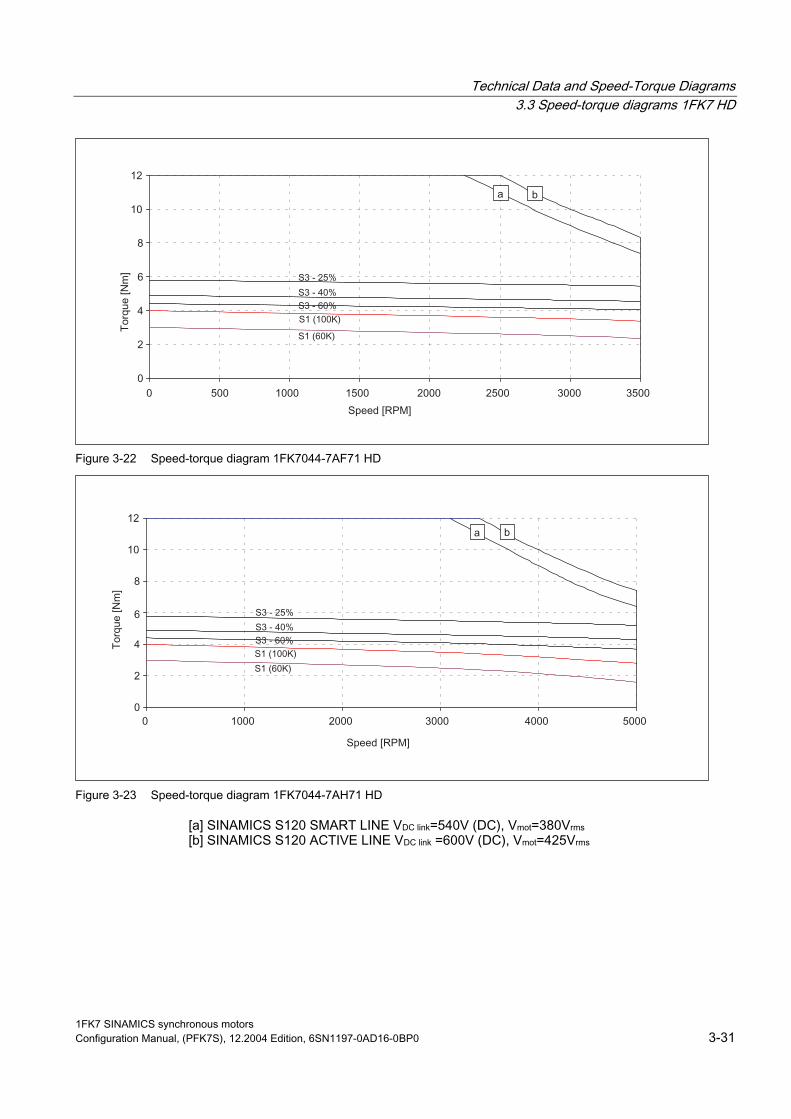
Figure 3-22 Speed-torque diagram 1FK7044-7AF71 HD
Figure 3-23 Speed-torque diagram 1FK7044-7AH71 HD
[a] SINAMICS S120 SMART LINE VDC link=540V (DC), Vmot=380Vrms [b] SINAMICS S120 ACTIVE LINE VDC link =600V (DC), Vmot=425Vrms
1FK7 SINAMICS synchronous motors Configuration Manual, (PFK7S), 12.2004 Edition, 6SN1197-0AD16-0BP0 3-31

Technical Data and Speed-Torque Diagrams 3.3 Speed-torque diagrams 1FK7 HD
Table 3-16 1FK7061 HD
Technical data Code Units –7AF71 –7AH71 Engineering data Rated speed Pole number Rated torque (100 K) Rated current Stall torque (60K) Stall torque (100K) Stall current (60K) Stall current (100K) Moment of inertia (with brake) Moment of inertia (without brake)
nN 2p MN(100 K) IN M0 (60 K) M0 (100 K) I0(60 K) I0(100 K) Jmot Jmot
RPM Nm A Nm Nm A A 10–4 kgm2 10–4 kgm2
3000 6 5.4 5.3 4.9 6.4 4.8 6.1 3.74 3.4
4500 6 4.3 5.9 4.9 6.4 7.0 8.0 3.74 3.4
Optimum operating point Optimum speed Optimum power
nopt Popt
RPM kW
3000 1.7
4500 2.03
Limiting data Max. perm. speed (mechan.) Max. torque Peak current
nmax Mmax Imax
RPM Nm A
6000 17.3 17.5
6000 17.3 25.3
Physical constants Torque constant Voltage constant
Rotating field inductance Electrical time constant Shaft torsional stiffness Mechanical time constant
Weight with brake Weight without brake
kT kE Rph LD Tel ct Tmech Tth m m
Nm/A V/1000 RPM Ohm mH ms Nm/rad ms min kg kg
1.0 66 0.74 20 27 37000 0.75 45 11.2 10
0.7 46 0.36 9.6 27 37000 0.75 45 11.2 10
Winding resistance at 20°C
Thermal time constant
1FK7 SINAMICS synchronous motors 3-32 Configuration Manual, (PFK7S), 12.2004 Edition, 6SN1197-0AD16-0BP0
Technical Data and Speed-Torque Diagrams 3.3 Speed-torque diagrams 1FK7 HD
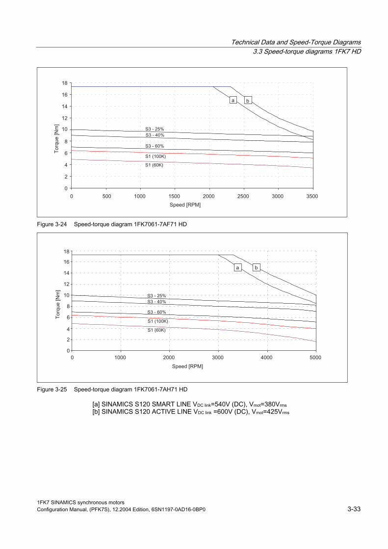
Figure 3-24 Speed-torque diagram 1FK7061-7AF71 HD
Figure 3-25 Speed-torque diagram 1FK7061-7AH71 HD
[a] SINAMICS S120 SMART LINE VDC link=540V (DC), Vmot=380Vrms [b] SINAMICS S120 ACTIVE LINE VDC link =600V (DC), Vmot=425Vrms
1FK7 SINAMICS synchronous motors Configuration Manual, (PFK7S), 12.2004 Edition, 6SN1197-0AD16-0BP0 3-33

Technical Data and Speed-Torque Diagrams 3.3 Speed-torque diagrams 1FK7 HD
Table 3-17 1FK7064 HD
Technical data Code Units –7AF71 –7AH71 Engineering data Rated speed Pole number Rated torque (100 K) Rated current Stall torque (60K) Stall torque (100K) Stall current (60K) Stall current (100K) Moment of inertia (with brake) Moment of inertia (without brake)
nN 2p MN(100 K) IN M0 (60 K) M0 (100 K) I0(60 K) I0(100 K) Jmot Jmot
RPM Nm A Nm Nm A A 10–4 kgm2 10–4 kgm2
3000 6 8.0 7.5 9.0 12 8.5 11 6.84 6.5
4500 6 5.0 7.0 9.0 12 12 15 6.84 6.5
Optimum operating point Optimum speed Optimum power
nopt Popt
RPM kW
3000 2.51
3500 2.75
Limiting data Max. perm. speed (mechan.) Max. torque Peak current
nmax Mmax Imax
RPM Nm A
6000 32 31
6000 32 42
Physical constants Torque constant Voltage constant
Rotating field inductance Electrical time constant Shaft torsional stiffness Mechanical time constant
Weight with brake Weight without brake
kT kE Rph LD Tel ct Tmech Tth m m
Nm/A V/1000 RPM Ohm mH ms Nm/rad ms min kg kg
1.03 68 0.35 10.7 30.5 30000 0.64 55 16.8 15.5
0.77 51 0.18 5.6 31.1 30000 0.59 55 16.8 15.5
Winding resistance at 20°C
Thermal time constant
1FK7 SINAMICS synchronous motors 3-34 Configuration Manual, (PFK7S), 12.2004 Edition, 6SN1197-0AD16-0BP0

Technical Data and Speed-Torque Diagrams 3.3 Speed-torque diagrams 1FK7 HD
Figure 3-26 Speed-torque diagram 1FK7064-7AF71 HD
Figure 3-27 Speed-torque diagram 1FK7064-7AH71 HD
[a] SINAMICS S120 SMART LINE VDC link=540V (DC), Vmot=380Vrms [b] SINAMICS S120 ACTIVE LINE VDC link =600V (DC), Vmot=425Vrms
1FK7 SINAMICS synchronous motors Configuration Manual, (PFK7S), 12.2004 Edition, 6SN1197-0AD16-0BP0 3-35

Technical Data and Speed-Torque Diagrams 3.3 Speed-torque diagrams 1FK7 HD
Table 3-18 1FK7082 HD
Technical data Code Units –7AF71 Engineering data Rated speed Pole number Rated torque (100 K) Rated current Stall torque (60K) Stall torque (100K) Stall current (60K) Stall current (100K) Moment of inertia (with brake) Moment of inertia (without brake)
nN 2p MN(100 K) IN M0 (60 K) M0 (100 K) I0(60 K) I0(100 K) Jmot Jmot
RPM Nm A Nm Nm A A 10–4 kgm2 10–4 kgm2
3000 8 8.0 6.7 10.5 14 8.0 10.6 16 14
Optimum operating point Optimum speed Optimum power
nopt Popt
RPM kW
3000 2.51
Limiting data Max. perm. speed (mechan.) Max. torque Peak current
nmax Mmax Imax
RPM Nm A
6000 40 36
Physical constants Torque constant Voltage constant
Rotating field inductance Electrical time constant Shaft torsional stiffness Mechanical time constant
Weight with brake Weight without brake
kT kE Rph LD Tel ct Tmech Tth m m
Nm/A V/1000 RPM Ohm mH ms Nm/rad ms min kg kg
1.33 88 0.43 8 23.2 101000 1.02 60 18.8 17.2
Winding resistance at 20°C
Thermal time constant
1FK7 SINAMICS synchronous motors 3-36 Configuration Manual, (PFK7S), 12.2004 Edition, 6SN1197-0AD16-0BP0

Technical Data and Speed-Torque Diagrams 3.3 Speed-torque diagrams 1FK7 HD
Figure 3-28 Speed-torque diagram 1FK7082-7AF71 HD
[a] SINAMICS S120 SMART LINE VDC link=540V (DC), Vmot=380Vrms [b] SINAMICS S120 ACTIVE LINE VDC link =600V (DC), Vmot=425Vrms
1FK7 SINAMICS synchronous motors Configuration Manual, (PFK7S), 12.2004 Edition, 6SN1197-0AD16-0BP0 3-37
Technical Data and Speed-Torque Diagrams 3.3 Speed-torque diagrams 1FK7 HD
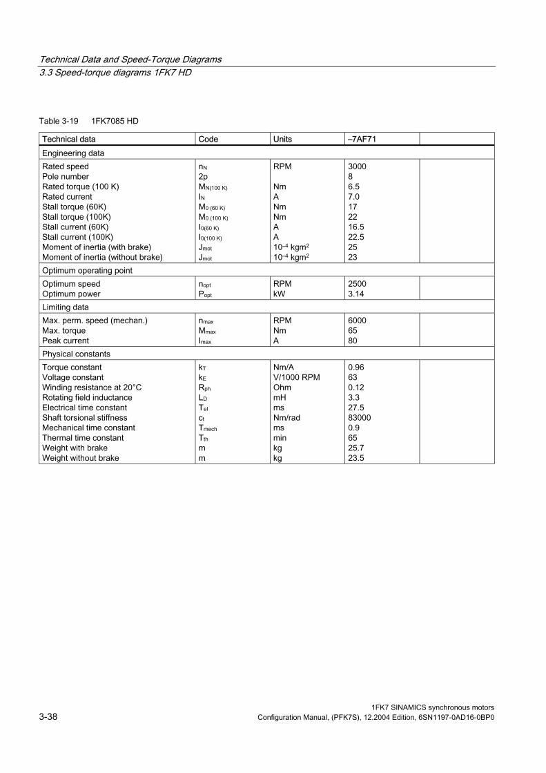
Table 3-19 1FK7085 HD
Technical data Code Units –7AF71 Engineering data Rated speed Pole number Rated torque (100 K) Rated current Stall torque (60K) Stall torque (100K) Stall current (60K) Stall current (100K) Moment of inertia (with brake) Moment of inertia (without brake)
nN 2p MN(100 K) IN M0 (60 K) M0 (100 K) I0(60 K) I0(100 K) Jmot Jmot
RPM Nm A Nm Nm A A 10–4 kgm2 10–4 kgm2
3000 8 6.5 7.0 17 22 16.5 22.5 25 23
Optimum operating point Optimum speed Optimum power
nopt Popt
RPM kW
2500 3.14
Limiting data Max. perm. speed (mechan.) Max. torque Peak current
nmax Mmax Imax
RPM Nm A
6000 65 80
Physical constants Torque constant Voltage constant
Rotating field inductance Electrical time constant Shaft torsional stiffness Mechanical time constant
Weight with brake Weight without brake
kT kE Rph LD Tel ct Tmech Tth m m
Nm/A V/1000 RPM Ohm mH ms Nm/rad ms min kg kg
0.96 63 0.12 3.3 27.5 83000 0.9 65 25.7 23.5
Winding resistance at 20°C
Thermal time constant
1FK7 SINAMICS synchronous motors 3-38 Configuration Manual, (PFK7S), 12.2004 Edition, 6SN1197-0AD16-0BP0

Technical Data and Speed-Torque Diagrams 3.3 Speed-torque diagrams 1FK7 HD
Figure 3-29 Speed-torque diagram 1FK7085-7AF71 HD
[a] SINAMICS S120 SMART LINE VDC link=540V (DC), Vmot=380Vrms [b] SINAMICS S120 ACTIVE LINE VDC link =600V (DC), Vmot=425Vrms
1FK7 SINAMICS synchronous motors Configuration Manual, (PFK7S), 12.2004 Edition, 6SN1197-0AD16-0BP0 3-39
Technical Data and Speed-Torque Diagrams 3.4 Cantilever force diagrams
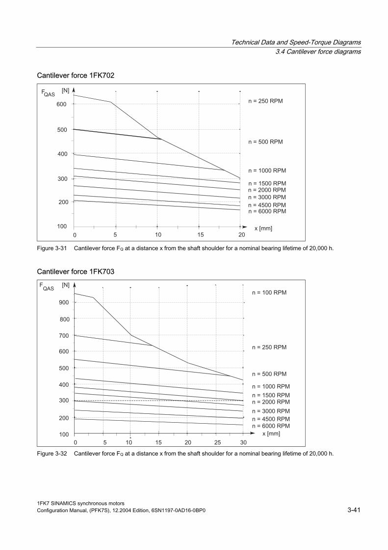
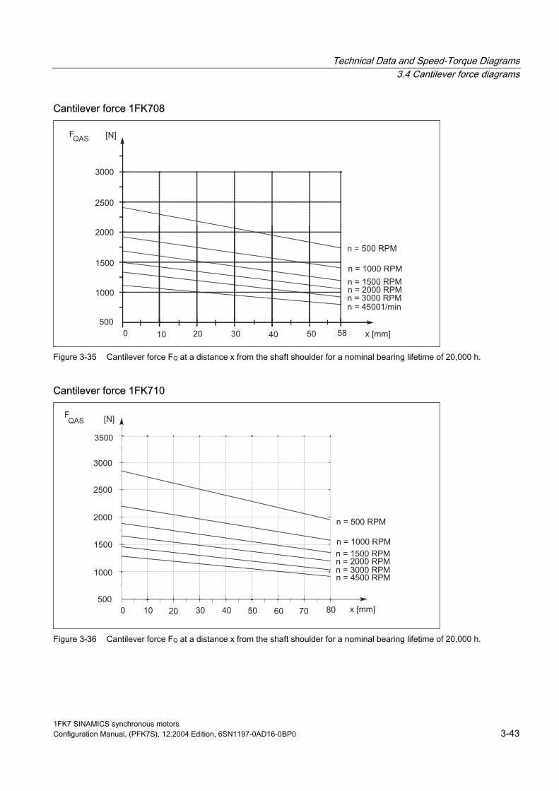
3.4 Cantilever force diagrams
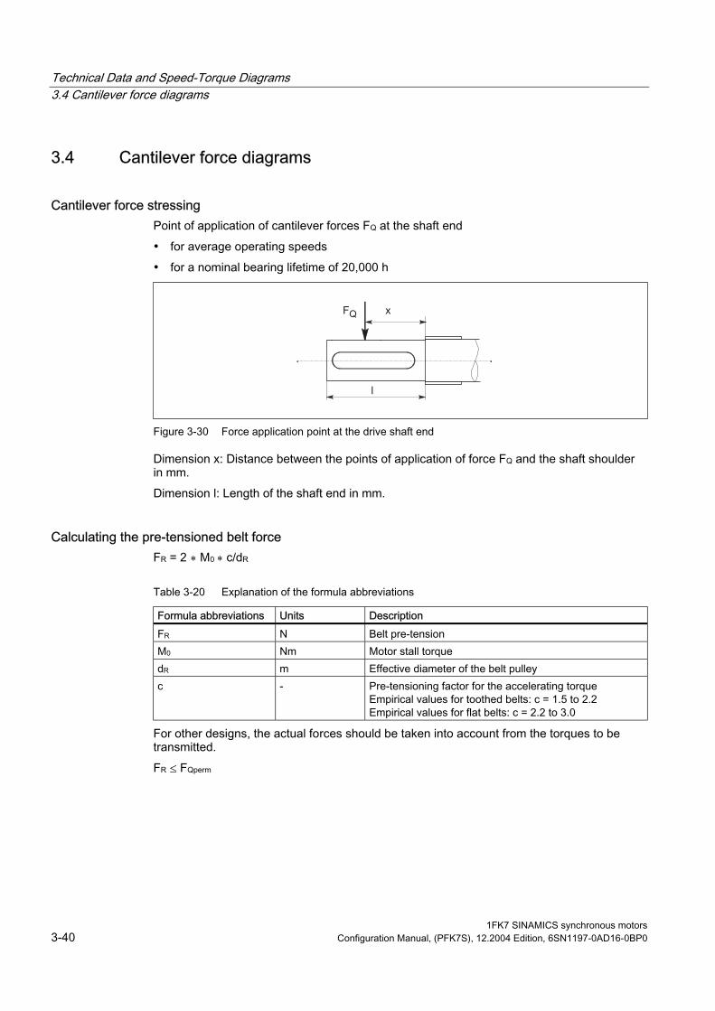
Cantilever force stressing Point of application of cantilever forces FQ at the shaft end
• for average operating speeds
• for a nominal bearing lifetime of 20,000 h
Figure 3-30 Force application point at the drive shaft end
Dimension x: Distance between the points of application of force FQ and the shaft shoulder in mm.
Dimension l: Length of the shaft end in mm.
Calculating the pre-tensioned belt force FR = 2 ∗ M0 ∗ c/dR
Table 3-20 Explanation of the formula abbreviations
Formula abbreviations Units Description FR N Belt pre-tension M0 Nm Motor stall torque dR m Effective diameter of the belt pulley c - Pre-tensioning factor for the accelerating torque
Empirical values for flat belts: c = 2.2 to 3.0 Empirical values for toothed belts: c = 1.5 to 2.2
For other designs, the actual forces should be taken into account from the torques to be transmitted.
FR ≤ FQperm
1FK7 SINAMICS synchronous motors 3-40 Configuration Manual, (PFK7S), 12.2004 Edition, 6SN1197-0AD16-0BP0
Technical Data and Speed-Torque Diagrams 3.4 Cantilever force diagrams
Cantilever force 1FK702
Figure 3-31 Cantilever force FQ at a distance x from the shaft shoulder for a nominal bearing lifetime of 20,000 h.
Cantilever force 1FK703
Figure 3-32 Cantilever force FQ at a distance x from the shaft shoulder for a nominal bearing lifetime of 20,000 h.
1FK7 SINAMICS synchronous motors Configuration Manual, (PFK7S), 12.2004 Edition, 6SN1197-0AD16-0BP0 3-41

Technical Data and Speed-Torque Diagrams 3.4 Cantilever force diagrams
Cantilever force 1FK704
Figure 3-33 Cantilever force FQ at a distance x from the shaft shoulder for a nominal bearing lifetime of 20,000 h.
Cantilever force 1FK706
Figure 3-34 Cantilever force FQ at a distance x from the shaft shoulder for a nominal bearing lifetime of 20,000 h.
1FK7 SINAMICS synchronous motors 3-42 Configuration Manual, (PFK7S), 12.2004 Edition, 6SN1197-0AD16-0BP0
Technical Data and Speed-Torque Diagrams 3.4 Cantilever force diagrams
Cantilever force 1FK708
Figure 3-35 Cantilever force FQ at a distance x from the shaft shoulder for a nominal bearing lifetime of 20,000 h.
Cantilever force 1FK710
Figure 3-36 Cantilever force FQ at a distance x from the shaft shoulder for a nominal bearing lifetime of 20,000 h.
1FK7 SINAMICS synchronous motors Configuration Manual, (PFK7S), 12.2004 Edition, 6SN1197-0AD16-0BP0 3-43

Technical Data and Speed-Torque Diagrams 3.5 Axial forces
3.5 Axial forces
Axial force stressing
Warning
Motors with integrated holding brake cannot be subject to axial forces!
When using, for example, helical toothed wheels as drive element, in addition to the radial force, there is also an axial force on the motor bearings. For axial forces, the spring-loading of the bearings can be overcome so that the rotor moves corresponding to the axial bearing play present (up to 0.2 mm).
The permissible axial force can be approximately calculated using the following formula:
FA = 0.35 ∙ FQ
1FK7 SINAMICS synchronous motors 3-44 Configuration Manual, (PFK7S), 12.2004 Edition, 6SN1197-0AD16-0BP0

Motor Components (Options) 4 4.1 Thermal motor protection
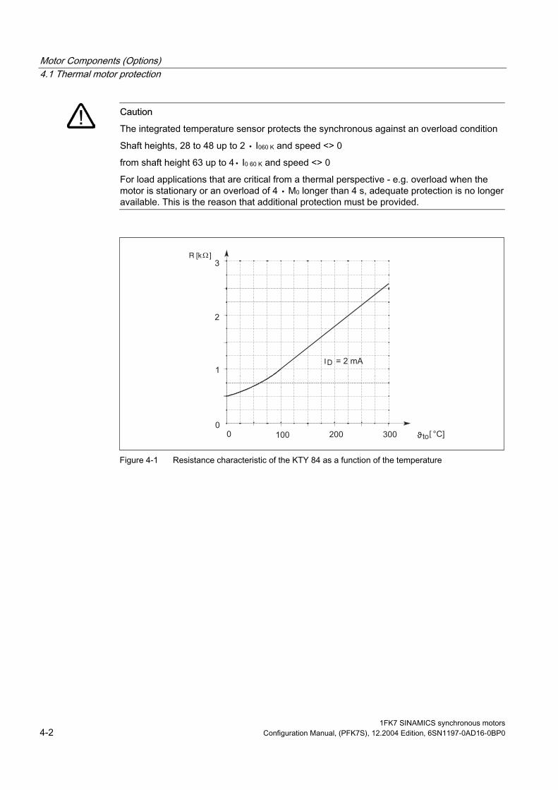
A temperature-dependent resistor is integrated as temperature sensor to monitor the motor temperature.
Table 4-1 Features and technical data
Type KTY 84 (PTC thermistor) Resistance when cold (20°C) approx. 580 Ohm Resistance when hot (100°C) approx. 1000 Ohm Connecting via signal cable Response temperature Pre-warning at 120 °C ± 5 °C
Alarm/trip at 145 °C ± 5 °C
The resistance of the KTY 84 thermistor changes proportionally to the winding temperature change.
The temperature signal is sensed and evaluated in the drive converter whose closed-loop control takes into account the temperature characteristic of the motor resistances.
When a fault occurs, an appropriate message is output at the drive converter. When the motor temperature increases, a message "Alarm motor overtemperature" is output; this must be externally evaluated. If this signal is not observed, the drive converter shuts down with the appropriate fault message when the motor limiting temperature or the shutdown temperature is exceeded.
Warning
If the user carries-out an additional high-voltage test, then the ends of the temperature sensor cables must be short-circuited before the test is carried-out!
If the test voltage is connected to a temperature sensor terminal, then it will be destroyed.
The polarity must be carefully observed.
The temperature sensor is designed so that the DIN/EN requirement for "protective separation" is fulfilled.
1FK7 SINAMICS synchronous motors Configuration Manual, (PFK7S), 12.2004 Edition, 6SN1197-0AD16-0BP0 4-1
Motor Components (Options) 4.1 Thermal motor protection
Caution
The integrated temperature sensor protects the synchronous against an overload condition
Shaft heights, 28 to 48 up to 2 ∙ I060 K and speed <> 0
from shaft height 63 up to 4∙ I0 60 K and speed <> 0
For load applications that are critical from a thermal perspective - e.g. overload when the motor is stationary or an overload of 4 ∙ M0 longer than 4 s, adequate protection is no longer available. This is the reason that additional protection must be provided.
[
I
R [kΩ
Figure 4-1 Resistance characteristic of the KTY 84 as a function of the temperature
1FK7 SINAMICS synchronous motors 4-2 Configuration Manual, (PFK7S), 12.2004 Edition, 6SN1197-0AD16-0BP0

Motor Components (Options) 4.2 Encoders
4.2 Encoders
4.2.1 Encoder overview The encoder is selected in the motor Order No. (MLFB) using the appropriate letter at the 14th position.
Note
The letter ID at the 14th position of the Order No. (MLFB) differs for motors with an without DRIVE-CLiQ.
Table 4-2 Encoder for motor with and without DRIVE-CLiQ
Motor types Incremental encoders
sin/cos 1 Vpp (for low shaft
heights) (I–2048)
Incremental encoders
sin/cos 1 Vpp (I–2048)
Absolute value encoders
EnDat (A–2048)
Absolute value encoders
EnDat (A-512)
Simple absolute value
encoders (A-32)
Resolvers 2-pole/
multi-pole
Order No. (MLFB) 14th position for motors with DRIVE-CLiQ
D D F L K U/ P
Order No. (MLFB) 14th position for motors without DRIVE-CLiQ
A A E H G S/ T
1FK7 02⃞ X X X 1FK7 03⃞ X X X 1FK7 04⃞ X X X X 1FK7 06⃞ X X X X 1FK7 08⃞ X X X X 1FK7 10⃞ X X X X
Notice
When the encoder is replaced, the position of the encoder system with respect to the motor EMF must be adjusted. Only qualified personnel may replace an encoder.
1FK7 SINAMICS synchronous motors Configuration Manual, (PFK7S), 12.2004 Edition, 6SN1197-0AD16-0BP0 4-3

Motor Components (Options) 4.3 Motors with DRIVE-CLiQ
4.3 Motors with DRIVE-CLiQ Motors with DRIVE-CLiQ have a sensor module that includes the encoder evaluation, the motor temperature sensing and an electronic rating plate.
This sensor module instead of the signal connector and has a 10-pin RJ45-plus socket.
Caution
The sensor module contains motor and encoder-specific data as well as an electronic rating plate. This is the reason that this sensor module may only be operated on the original motor - and may not be mounted onto other motors or replaced by a sensor module from other motors.
The sensor module has direct contact to components that can be destroyed by electrostatic discharge (ESDS). Neither hands nor tools that could be electrostatically charged may come into contact with the connections.
Cables For all encoder types (incremental encoder, absolute value encoder, resolver), the same DRIVE-CLiQ cable is used.
The following cable should be used to connect an encoder:
Table 4-3 Prefabricated cable
6FX 002 - DC - 0
↓ ↓ 5 MOTION-CONNECT500 8 MOTION-CONNECT800
↓↓↓ Length Max. cable length 100 m Max. cable length 50 m
Only prefabricated cables from Siemens (MOTION-CONNECT) may be used.
Additional technical data and length code, refer to Catalog, Chapter "MOTION-CONNECT connection system"
1FK7 SINAMICS synchronous motors 4-4 Configuration Manual, (PFK7S), 12.2004 Edition, 6SN1197-0AD16-0BP0

Motor Components (Options) 4.4 Motors without DRIVE-CLiQ
4.4 Motors without DRIVE-CLiQ
4.4.1 Incremental encoders Function:
• Angular measuring system for commutation
• Speed actual value sensing
• Indirect incremental measuring system for the position control loop
• One zero pulse (reference mark) per revolution
Table 4-4 Technical data, incremental encoders sin/cos 1Vpp
Features Incremental encoders sin/cos 1 Vpp (I–2048)
Incremental encoders sin/cos 1 Vpp (low SH) (I–2048)
Mech. limiting speed 15000 RPM 12000 RPM Operating voltage 5V ± 5% 5V ± 5% Current consumption max. 150 mA max. 150 mA Resolution, incremental 2048 2048 Incremental signals 1 Vpp 1 Vpp Angular error ± 40" ± 80" C–D track (rotor position) available available
1FK7 SINAMICS synchronous motors Configuration Manual, (PFK7S), 12.2004 Edition, 6SN1197-0AD16-0BP0 4-5

Motor Components (Options) 4.4 Motors without DRIVE-CLiQ
Figure 4-2 Signal sequence and assignment for a positive direction of rotation
1FK7 SINAMICS synchronous motors 4-6 Configuration Manual, (PFK7S), 12.2004 Edition, 6SN1197-0AD16-0BP0

Motor Components (Options) 4.4 Motors without DRIVE-CLiQ
Connection assignment for 17-pin flange-mounted socket with pin contacts
Table 4-5 Connection assignment for 17-pin flange-mounted socket
PIN No. Signal 1 A+
2 A–
3 R+
4 D–
5 C+
6 C–
7 M encoder
8 +Temp
9 –Temp
10 P encoder
11 B+
12 B–
13 R–
14 D+
15 0 V sense
16 5 V sense
17 not connected
45
6
7
8910
11
1
23
14
17 15
1612
13
When viewing the plug-in side (pins)
Cables
Table 4-6 Prefabricated cable
6FX 002 - 2CA31 - 0 ↓
↓ 5 MOTION-CONNECT500 8 MOTION-CONNECT800
↓↓↓ Length Max. cable length 100 m
Additional technical data and length code, refer to Catalog, Chapter "MOTION-CONNECT connection system"
1FK7 SINAMICS synchronous motors Configuration Manual, (PFK7S), 12.2004 Edition, 6SN1197-0AD16-0BP0 4-7

Motor Components (Options) 4.4 Motors without DRIVE-CLiQ
4.4.2 Absolute value encoder Function:
• Angular measuring system to impress the current
• Speed actual value sensing
• Absolute measuring system for the position control loop Table 4-7 Technical data, absolute value encoder
Features Absolute value encoder EnDat (A–2048)
Absolute value encoder EnDat (A–512)
Simple absolute value encoder (A–32)
Mech. limiting speed 12000 RPM 12000 RPM 12000 RPM Operating voltage 5V ± 5% 5V ± 5% 5V ± 5% Current consumption max. 300 mA max. 200 mA max. 300 mA Incremental resolution (periods per revolution)
2048 512 32
Absolute resolution (coded revolutions)
4096 4096 4096
Incremental signals 1 Vpp 1 Vpp 1 Vpp Serial absolute position interface
EnDat EnDat EnDat
Angular error ± 40" ± 80" ± 400"
Note
The thermally permissible motor rated torque is reduced by 10% as a result of the reduced maximum operating temperature of the absolute value encoder with respect to incremental encoders.
Figure 4-3 Output signals, absolute value encoders
1FK7 SINAMICS synchronous motors 4-8 Configuration Manual, (PFK7S), 12.2004 Edition, 6SN1197-0AD16-0BP0

Motor Components (Options) 4.4 Motors without DRIVE-CLiQ
Connection assignment for 17–pin flange-mounted socket with pin contacts
Table 4-8 Connection assignment for 17–pin flange-mounted socket
PIN No. Signal 1 A+
2 A–
3 + data
4 not connected
5 +clock
6 not connected
7 M encoder
8 +Temp
9 –Temp
10 P encoder
11 B+
12 B–
13 –Data
14 –clock
15 0 V sense
16 5 V sense
17 not connected
45
6
7
8910
11
1
23
14
17 15
1612
13
When viewing the plug-in side (pins)
Cables
Table 4-9 Prefabricated cable
6FX 002 - 2EQ10 - 0 ↓
↓ 5 MOTION-CONNECT500 8 MOTION-CONNECT800
↓↓↓ Length Max. cable length 100 m
Additional technical data and length code, refer to Catalog, Chapter "MOTION-CONNECT connection system"
1FK7 SINAMICS synchronous motors Configuration Manual, (PFK7S), 12.2004 Edition, 6SN1197-0AD16-0BP0 4-9
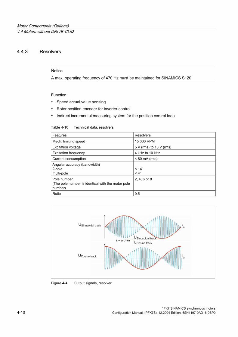
Motor Components (Options) 4.4 Motors without DRIVE-CLiQ
4.4.3 Resolvers
Notice
A max. operating frequency of 470 Hz must be maintained for SINAMICS S120.
Function:
• Speed actual value sensing
• Rotor position encoder for inverter control
• Indirect incremental measuring system for the position control loop
Table 4-10 Technical data, resolvers
Features Resolvers Mech. limiting speed 15 000 RPM Excitation voltage 5 V (rms) to 13 V (rms) Excitation frequency 4 kHz to 10 kHz Current consumption < 80 mA (rms) Angular accuracy (bandwidth) 2-pole multi-pole
< 14' < 4'
Pole number al with the motor pole
number)
2, 4, 6 or 8
Ratio 0.5
(The pole number is identic
Figure 4-4 Output signals, resolver
1FK7 SINAMICS synchronous motors 4-10 Configuration Manual, (PFK7S), 12.2004 Edition, 6SN1197-0AD16-0BP0

Motor Components (Options) 4.4 Motors without DRIVE-CLiQ
Connection assignment for 12–pin flange-mounted socket with pin contacts
Table 4-11 Connection assignment for 12–pin flange-mounted socket
PIN No. Signal 1 S2
2 S4
3 not connected
4 not connected
5 not connected
6 not connected
7 R2/R3
8 +Temp
9 –Temp
10 R1
11 S1
12 S3
2
1
10 12
1163
9 8
7
4 5
When viewing the plug-in side (pins)
Cables
Table 4-12 Prefabricated cable
6FX 002 - 2CF02 - 0
↓ ↓ 5 MOTION-CONNECT500 8 MOTION-CONNECT800
↓↓↓ Length 2-pole resolver: Max. cable length 50 m Multi-pole resolver: Max. cable length 130 m
Additional technical data and length code, refer to Catalog, Chapter "MOTION-CONNECT connection system"
1FK7 SINAMICS synchronous motors Configuration Manual, (PFK7S), 12.2004 Edition, 6SN1197-0AD16-0BP0 4-11

Motor Components (Options) 4.5 Holding brake (option)
1FK7 SINAMICS synchronous motors 4-12 Configuration Manual, (PFK7S), 12.2004 Edition, 6SN1197-0AD16-0BP0
4.5 Holding brake (option) For a description of the function, refer to the documentation "General Section for Synchronous motors".
Table 4-13 Technical data of the holding brakes used for 1FK7 motors
Motor type Brake type Holding torque M4 1)
DC current Opening time with varistor
Closing time with varistor
Highest switched energy
[Nm] [A] [ms] [ms] [J] 1FK7 CT permanent-magnet brakes 1FK7022 EBD 0.11 BN 1 0.3 30 20 8 1FK7032 EBD 0.13 BN 1.1 0.4 50 30 17 1FK704⃞ EBD 0.3 BV 3.2 0.6 70 30 74 1FK706⃞ EBD 0.8 BK 13 0.8 100 50 400 1FK7080 EBD 1.5 BN 10 0.8 100 50 400 1FK7083 1FK7100
EBD 2 BY 22 0.9 200 60 1400
1FK7101 1FK7103 1FK7105
EBD 3.5 BV 41 1.0 300 70 3000
1FK7 HD spring-operated brakes 1FK7033 1EB 14–30 1.3 0.5 100 40 14 1FK704⃞ 1EB 20-40 4 0.6 150 50 96 1FK706⃞ 1EB 28-60 12 0.8 150 50 230 1FK708⃞ 1EB 35-80 22 1.2 200 60 700
1) Standardized acc. to VDE 0580 with varistor circuit
Holding torque The holding torque M4 is the minimum brake torque in steady-state operation (when the motor is at a standstill).

Motor Components (Options) 4.6 Planetary gearbox (option)
1FK7 SINAMICS synchronous motors Configuration Manual, (PFK7S), 12.2004 Edition, 6SN1197-0AD16-0BP0 4-13
4.6 Planetary gearbox (option) Planetary gearboxes (alpha company, LP series) - selection table for 1FK7 motors
Table 4-14 Technical data of the planetary gearboxes which can be used for 1FK7 CT and 1FK7 HD motors
Servo-motor Non-ventilated Type
Planetary gearbox 1 stage Rotary play ≤ 12 arcmin Type
Gearbox weight approx.
Available gearbox ratios
Max. perm. input
speed 1)
Max. perm. output
torque 1)
Max. perm. drive-out
shaft load 2)
Moment of inertia Gear-boxes
[kg] i = 5 i = 10 nG1 [RPM]
MG2 at i = 5 [Nm]
MG2 at i = 10 [Nm]
Fr [N]
JG at i = 5/10
[10–4 kgm2]
1FK7022 LP050–M01 0.77 X – 8000 11.5 10.5 650 0.059 1FK7022 LP070–M01 1.9 – X 6000 32 29 1450 0.28 1FK7032 LP070–M01 1.9 X X 6000 32 29 1450 0.28 1FK7033 LP070–M01 1.9 X X 6000 32 29 1450 0.28 1FK7040 LP090–M01 4.1 X X 6000 80 72 2400 1.77 1FK7042 LP090–M01 4.1 X X 6000 80 72 2400 1.77 1FK7043 LP090–M01 4.1 X X 6000 80 72 2400 1.77 1FK7044 LP090–M01 4.1 X X 6000 80 72 2400 1.77 1FK7060 LP120–M01 9 X X 4800 200 180 4600 5.42 1FK7061 LP120–M01 9 X X 4800 200 180 4600 5.42 1FK7063 LP120–M01 9 X X 4800 200 180 4600 5.42 1FK7064 LP120–M01 9 X X 3) 4800 200 180 4600 5.42 1FK7080 LP155–M01 17.5 X X 3600 400 320 7500 25.73 1FK7082 LP155–M01 17.5 X X 3600 400 320 7500 25.73 1FK7083 LP155–M01 17.5 X X 3600 400 320 7500 25.73 1FK7085 LP155–M01 17.5 X X 3) 3600 400 320 7500 25.73 1FK7100 LP155–M01 17.5 X – 3600 400 320 7500 25.73 1FK7101 LP155–M01 17.5 X – 3600 400 320 7500 25.73 1FK7103 LP155–M01 17.5 X – 3600 400 320 7500 25.73 1FK7105 LP155–M01 17.5 X – 3600 400 320 7500 25.73 Code: Gearbox shaft with fitted key
V40 V42
1) Values for cyclic/positioning operation S3 60% (switch-on duration < 60% or switch-on duration < 20 min) 2) referred to the center of the drive-out shaft, at 100 RPM 3) It is necessary to reduce the max. motor torque

Motor Components (Options) 4.6 Planetary gearbox (option)
Continuous duty S1 At the rated speed and rated torque, continuous duty is permissible. A gearbox temperature of 90° C may not permissible to exceeded.
Table 4-15 Continuous duty S1
Planetary gearbox 1-stage Torsional play ≤12 arcmin
Rated speed [RPM]
Max. permissible output torque1) [Nm]
Type nN1 M at i = 5 M at i = 10 LP50–M01 4000 5.7 5.2
LP070–M01 3700 16 15 LP090–M01 3400 40 35 LP120–M01 2600 100 90 LP155–M01 2000 290 170
N2 N2
1) Values for cycle/positioning operation S3 60% (switch-on duration < 60% or switch-on duration < 20 min)
The gearboxes are suitable for every mounting position. The gearboxes have an IP 64 degree of protection. Gearboxes without key are not available.
Dimensions of 1FK7 CT/HD with planetary gearbox from the alpha company, series LP
Figure 4-5 Dimensions 1FK7 CT and 1FK7 HD motor with planetary gearbox
1FK7 SINAMICS synchronous motors 4-14 Configuration Manual, (PFK7S), 12.2004 Edition, 6SN1197-0AD16-0BP0
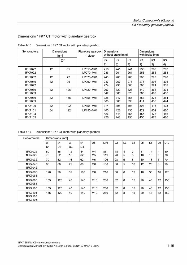
Motor Components (Options) 4.6 Planetary gearbox (option)
Dimensions 1FK7 CT motor with planetary gearbox
Table 4-16 Dimensions 1FK7 CT motor with planetary gearbox
Dimensions [mm]
Dimensions without brake [mm]
Dimensions with brake [mm]
Servomotors
h1 ⃞F
Planetary gearbox 1-stage
K2 2)
K2 3)
K2 4)
K3 2)
K3 3)
K3 4)
1FK7022 1FK7022
42 55 LP050–M01 LP070–M01
216 236
241 261
241 261
238 258
263 283
263 283
1FK7032 42 72 LP070–M01 240 265 265 265 290 290 1FK7040 1FK7042
42 96 LP090–M01 247 274
267 295
276 303
276 303
296 324
305 332
1FK7060 1FK7063
42 126 LP120–M01 297 342
320 365
328 373
340 385
363 408
371 416
1FK7080 1FK7083
42 155 LP155–M01 325 363
347 385
355 393
353 414
375 436
384 444
1FK7100 42 192 LP155–M01 374 396 404 393 415 423 1FK7101 1FK7103 1FK7105
64 192 LP155–M01 400 426 426
422 448 448
430 456 456
429 455 455
452 478 478
460 486 486
Table 4-17 Dimensions 1FK7 CT motor with planetary gearbox
Dimensions [mm] Servomotors ∅ D1
∅ D2
∅ D3
∅ D4
D5 L16 L2 L3 L4 L5 L8 L9 L10
1FK7022 1FK7022
50 70
35 52
12 16
44 62
M4 M5
88 119
18 28
4 5
7 8
8 10
14 18
4 5
50 70
1FK7032 70 52 16 62 M6 126 28 5 8 10 18 5 70 1FK7040 1FK7042
90 68 22 80 M6 158 36 5 10 12 25 6 90
1FK7060 1FK7063
120 90 32 108 M8 210 58 6 12 16 35 10 120
1FK7080 1FK7083
155 120 40 140 M10 266 82 8 15 20 43 12 150
1FK7100 155 120 40 140 M10 266 82 8 15 20 43 12 150 1FK7101 1FK7103 1FK7105
155 120 40 140 M10 266 82 8 15 20 43 12 150
1FK7 SINAMICS synchronous motors Configuration Manual, (PFK7S), 12.2004 Edition, 6SN1197-0AD16-0BP0 4-15

Motor Components (Options) 4.6 Planetary gearbox (option)
Dimensions 1FK7 HD motor with planetary gearbox
Table 4-18 Dimensions 1FK7 HD motor with planetary gearbox
Dimensions [mm]
Dimensions without brake [mm]
Dimensions with brake [mm]
Servomotors
h1 ⃞F
Planetary gearbox 1-stage
K2 2)
K2 3)
K2 4)
K3 2)
K3 3)
K3 4)
1FK7033 42 72 LP070–M01 260 285 285 285 310 310 1FK7043 1FK7044
42 96 LP090–M01 303 328
324 349
332 357
332 357
352 377
361 386
1FK7061 1FK7064
42 126 LP120–M01 325 389
348 412
357 421
368 432
391 455
400 464
1FK7082 1FK7085
42 64
155 LP155–M01 370 430
393 453
401 461
423 473
445 495
454 504
Table 4-19 Dimensions 1FK7 HD motor with planetary gearbox
Dimensions [mm]
Servomotors
∅ D1
∅ D2
∅ D3
∅ D4
D5 L16 L2 L3 L4 L5 L8 L9 L10
1FK7033 70 52 16 62 M5 126 28 5 8 10 18 5 70 1FK7043 1FK7044
90 68 22 80 M6 158 36 5 10 12 25 6 90
1FK7061 1FK7064
120 90 32 108 M8 210 58 6 12 16 35 10 120
1FK7082 1FK7085
155 120 40 140 M10 266 82 8 15 20 43 12 150
1FK7 SINAMICS synchronous motors 4-16 Configuration Manual, (PFK7S), 12.2004 Edition, 6SN1197-0AD16-0BP0

Dimension Drawings 5 5.1 Introduction
Note
Siemens AG reserves the right to change the dimensions of the motors as part of mechanical design improvements without prior notice. This means that dimensions drawings can go out-of-date. Up-to-date dimension drawings can be requested at no charge from your local SIEMENS sales department.
1FK7 SINAMICS synchronous motors Configuration Manual, (PFK7S), 12.2004 Edition, 6SN1197-0AD16-0BP0 5-1

Dimension Drawings 5.2 1FK7 CT with DRIVE-CLiQ
5.2 1FK7 CT with DRIVE-CLiQ
Figure 5-1 1FK702_-5A_DQ
1FK7 SINAMICS synchronous motors 5-2 Configuration Manual, (PFK7S), 12.2004 Edition, 6SN1197-0AD16-0BP0
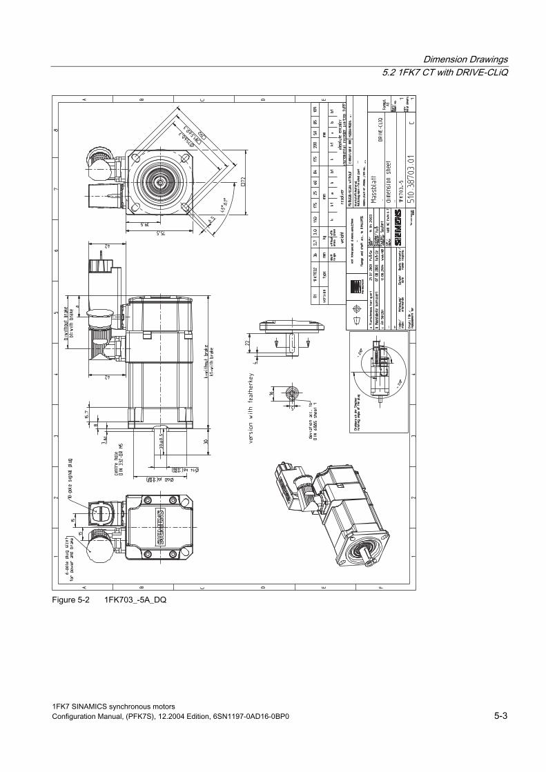
Dimension Drawings 5.2 1FK7 CT with DRIVE-CLiQ
Figure 5-2 1FK703_-5A_DQ
1FK7 SINAMICS synchronous motors Configuration Manual, (PFK7S), 12.2004 Edition, 6SN1197-0AD16-0BP0 5-3
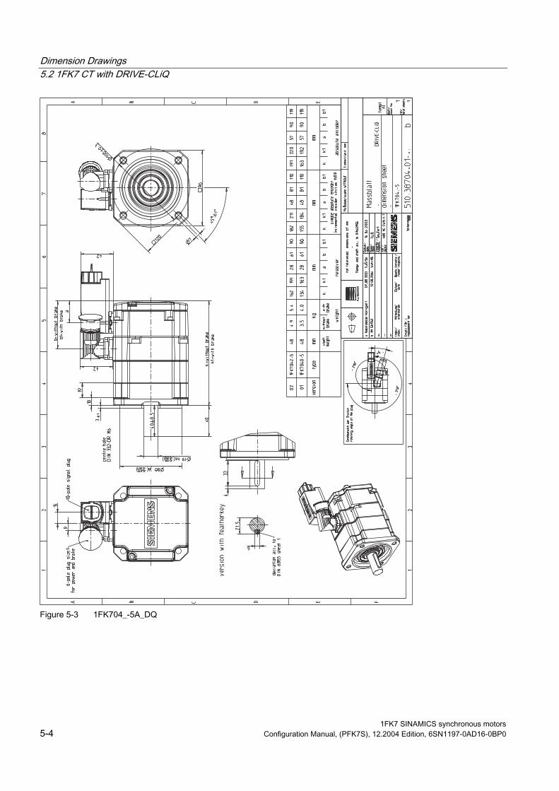
Dimension Drawings 5.2 1FK7 CT with DRIVE-CLiQ
Figure 5-3 1FK704_-5A_DQ
1FK7 SINAMICS synchronous motors 5-4 Configuration Manual, (PFK7S), 12.2004 Edition, 6SN1197-0AD16-0BP0
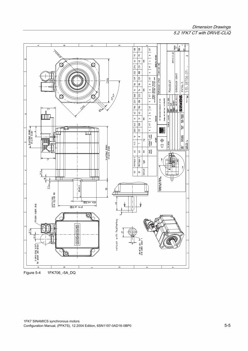
Dimension Drawings 5.2 1FK7 CT with DRIVE-CLiQ
Figure 5-4 1FK706_-5A_DQ
1FK7 SINAMICS synchronous motors Configuration Manual, (PFK7S), 12.2004 Edition, 6SN1197-0AD16-0BP0 5-5
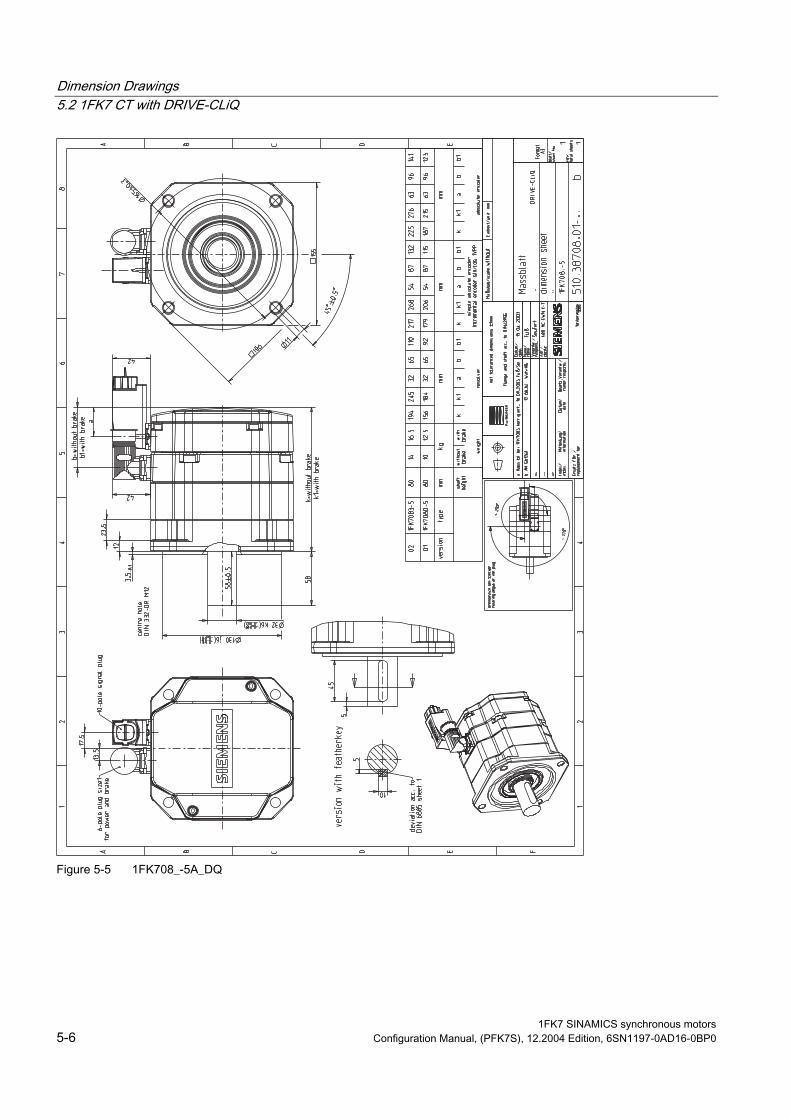
Dimension Drawings 5.2 1FK7 CT with DRIVE-CLiQ
Figure 5-5 1FK708_-5A_DQ
1FK7 SINAMICS synchronous motors 5-6 Configuration Manual, (PFK7S), 12.2004 Edition, 6SN1197-0AD16-0BP0
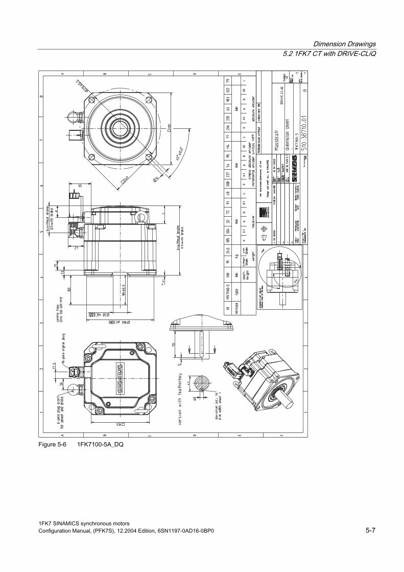
Dimension Drawings 5.2 1FK7 CT with DRIVE-CLiQ
Figure 5-6 1FK7100-5A_DQ
1FK7 SINAMICS synchronous motors Configuration Manual, (PFK7S), 12.2004 Edition, 6SN1197-0AD16-0BP0 5-7

Dimension Drawings 5.2 1FK7 CT with DRIVE-CLiQ
Figure 5-7 1FK7101_1FK7103_5A_DQ
1FK7 SINAMICS synchronous motors 5-8 Configuration Manual, (PFK7S), 12.2004 Edition, 6SN1197-0AD16-0BP0
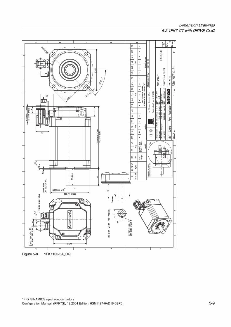
Dimension Drawings 5.2 1FK7 CT with DRIVE-CLiQ
Figure 5-8 1FK7105-5A_DQ
1FK7 SINAMICS synchronous motors Configuration Manual, (PFK7S), 12.2004 Edition, 6SN1197-0AD16-0BP0 5-9

Dimension Drawings 5.3 1FK7 HD with DRIVE-CLiQ
5.3 1FK7 HD with DRIVE-CLiQ
Figure 5-9 1FK703_-7A_DQ
1FK7 SINAMICS synchronous motors 5-10 Configuration Manual, (PFK7S), 12.2004 Edition, 6SN1197-0AD16-0BP0

Dimension Drawings 5.3 1FK7 HD with DRIVE-CLiQ
Figure 5-10 1FK704_-7A_DQ
1FK7 SINAMICS synchronous motors Configuration Manual, (PFK7S), 12.2004 Edition, 6SN1197-0AD16-0BP0 5-11

Dimension Drawings 5.3 1FK7 HD with DRIVE-CLiQ
Figure 5-11 1FK706_-7A_DQ
1FK7 SINAMICS synchronous motors 5-12 Configuration Manual, (PFK7S), 12.2004 Edition, 6SN1197-0AD16-0BP0
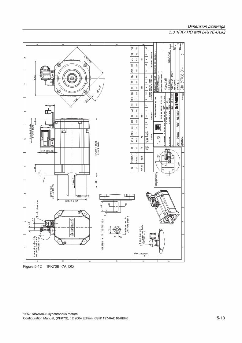
Dimension Drawings 5.3 1FK7 HD with DRIVE-CLiQ
Figure 5-12 1FK708_-7A_DQ
1FK7 SINAMICS synchronous motors Configuration Manual, (PFK7S), 12.2004 Edition, 6SN1197-0AD16-0BP0 5-13

Dimension Drawings 5.4 1FK7 CT without DRIVE-CLiQ
5.4 1FK7 CT without DRIVE-CLiQ
Figure 5-13 1FK702_-5
1FK7 SINAMICS synchronous motors 5-14 Configuration Manual, (PFK7S), 12.2004 Edition, 6SN1197-0AD16-0BP0

Dimension Drawings 5.4 1FK7 CT without DRIVE-CLiQ
Figure 5-14 1FK703_-5
1FK7 SINAMICS synchronous motors Configuration Manual, (PFK7S), 12.2004 Edition, 6SN1197-0AD16-0BP0 5-15
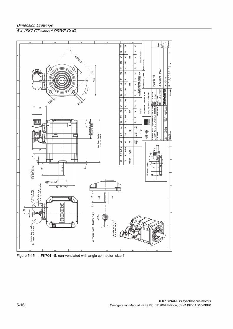
Dimension Drawings 5.4 1FK7 CT without DRIVE-CLiQ
Figure 5-15 1FK704_-5, non-ventilated with angle connector, size 1
1FK7 SINAMICS synchronous motors 5-16 Configuration Manual, (PFK7S), 12.2004 Edition, 6SN1197-0AD16-0BP0
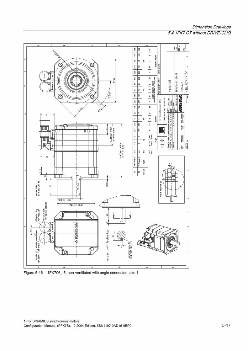
Dimension Drawings 5.4 1FK7 CT without DRIVE-CLiQ
Figure 5-16 1FK706_-5, non-ventilated with angle connector, size 1
1FK7 SINAMICS synchronous motors Configuration Manual, (PFK7S), 12.2004 Edition, 6SN1197-0AD16-0BP0 5-17

Dimension Drawings 5.4 1FK7 CT without DRIVE-CLiQ
Figure 5-17 1FK708_-5, non-ventilated with angle connector, size 1
1FK7 SINAMICS synchronous motors 5-18 Configuration Manual, (PFK7S), 12.2004 Edition, 6SN1197-0AD16-0BP0

Dimension Drawings 5.4 1FK7 CT without DRIVE-CLiQ
Figure 5-18 1FK7100-5, non-ventilated with angled connector, size 1
1FK7 SINAMICS synchronous motors Configuration Manual, (PFK7S), 12.2004 Edition, 6SN1197-0AD16-0BP0 5-19

Dimension Drawings 5.4 1FK7 CT without DRIVE-CLiQ
Figure 5-19 1FK710_-5, non-ventilated with angle connector, size 1.5
1FK7 SINAMICS synchronous motors 5-20 Configuration Manual, (PFK7S), 12.2004 Edition, 6SN1197-0AD16-0BP0

Dimension Drawings 5.4 1FK7 CT without DRIVE-CLiQ
Figure 5-20 1FK7105-5
1FK7 SINAMICS synchronous motors Configuration Manual, (PFK7S), 12.2004 Edition, 6SN1197-0AD16-0BP0 5-21

Dimension Drawings 5.5 1FK7 HD without DRIVE-CLiQ
5.5 1FK7 HD without DRIVE-CLiQ
Figure 5-21 1FK703_-7
1FK7 SINAMICS synchronous motors 5-22 Configuration Manual, (PFK7S), 12.2004 Edition, 6SN1197-0AD16-0BP0
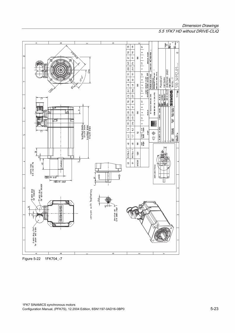
Dimension Drawings 5.5 1FK7 HD without DRIVE-CLiQ
Figure 5-22 1FK704_-7
1FK7 SINAMICS synchronous motors Configuration Manual, (PFK7S), 12.2004 Edition, 6SN1197-0AD16-0BP0 5-23

Dimension Drawings 5.5 1FK7 HD without DRIVE-CLiQ
Figure 5-23 1FK706_-7
1FK7 SINAMICS synchronous motors 5-24 Configuration Manual, (PFK7S), 12.2004 Edition, 6SN1197-0AD16-0BP0
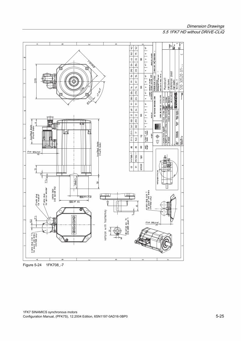
Dimension Drawings 5.5 1FK7 HD without DRIVE-CLiQ
Figure 5-24 1FK708_-7
1FK7 SINAMICS synchronous motors Configuration Manual, (PFK7S), 12.2004 Edition, 6SN1197-0AD16-0BP0 5-25
Dimension Drawings 5.5 1FK7 HD without DRIVE-CLiQ
1FK7 SINAMICS synchronous motors 5-26 Configuration Manual, (PFK7S), 12.2004 Edition, 6SN1197-0AD16-0BP0

Appendix A A.1 References
An overview of publications that is updated monthly is provided in a number of languages in the Internet at:
<http://www.siemens.com/motioncontrol> erview" through "Support", "Technical Documentation", "Documentation Ov
General Documentation
/D 21.2/ SINAMICS S120 Catalog SINAMICS S120
Servo Control Drive System
/NC 60/ SINUMERIK and SIMODRIVE
Automation Systems for Machine Tools
Catalog
/DA65.3/ SIMOVERT MASTERDRIVES
Synchronous and Induction Motors for SIMOVERT MASTERDRIVES
Catalog
Electronic Documentation
/CD1/ DOC ON CD The SINUMERIK System
MODRIVE 611D) (includes all SINUMERIK 840D/810D and SI
/CD2/ DOC ON CD The SINAMICS System
1FK7 SINAMICS synchronous motors Configuration Manual, (PFK7S), 12.2004 Edition, 6SN1197-0AD16-0BP0 A-1

Appendix A.1 References
Manufacturer/Service Documentation
/PJAL/ Configuration Manual, Synchronous Motors SINAMICS S120, SIMODRIVE 611, SIMOVERT MASTERDRIVES
Synchronous Motors General Section
/PFK7S/ Configuration Manual, Synchronous Motors SINAMICS S120
1FK7 Synchronous Motors
/PFT6S/ Configuration Manual, Synchronous Motors SINAMICS S120
1FT6 Synchronous Motors
/PMH2/ Installation Manual, Hollow Shaft Measuring System SINAMICS S120, SIMODRIVE 611, SIMOVERT MASTERDRIVES,
SIMAG H2 Hollow-Shaft Measuring System
/PFK7/ Configuration Manual, Synchronous Motors SIMODRIVE 611, SIMOVERT MASTERDRIVES
1FK7 Synchronous Motors
/PFT6/ Configuration Manual, Synchronous Motors SIMODRIVE 611, SIMOVERT MASTERDRIVES
1FT6 Synchronous Motors
/PFK6/ Configuration Manual, Synchronous Motors SIMODRIVE 611, SIMOVERT MASTERDRIVES
1FK6 Synchronous Motors
/PFS6/ Configuration Manual, Synchronous Motors SIMOVERT MASTERDRIVES
1FS6 Synchronous Motors, Explosion-Protected
/PFU/ Configuration Manual, Synchronous Motors SINAMICS S120, SIMOVERT MASTERDRIVES, MICROMASTER
SIEMOSYN Synchronous Motors 1FU8
1FK7 SINAMICS synchronous motors A-2 Configuration Manual, (PFK7S), 12.2004 Edition, 6SN1197-0AD16-0BP0
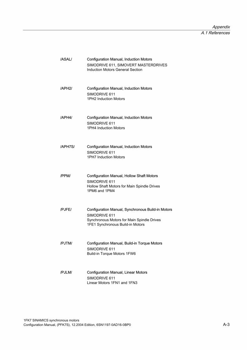
Appendix A.1 References
/ASAL/ Configuration Manual, Induction Motors SIMODRIVE 611, SIMOVERT MASTERDRIVES
Induction Motors General Section
/APH2/ Configuration Manual, Induction Motors SIMODRIVE 611
1PH2 Induction Motors
/APH4/ Configuration Manual, Induction Motors SIMODRIVE 611
1PH4 Induction Motors
/APH7S/ Configuration Manual, Induction Motors SIMODRIVE 611
1PH7 Induction Motors
/PPM/ Configuration Manual, Hollow Shaft Motors SIMODRIVE 611
Hollow Shaft Motors for Main Spindle Drives 1PM6 and 1PM4
/PJFE/ Configuration Manual, Synchronous Build-in Motors SIMODRIVE 611
Synchronous Motors for Main Spindle Drives 1FE1 Synchronous Build-in Motors
/PJTM/ Configuration Manual, Build-in Torque Motors SIMODRIVE 611
W6
Build-in Torque Motors 1F
/PJLM/ Configuration Manual, Linear Motors SIMODRIVE 611
N3
Linear Motors 1FN1 and 1F
1FK7 SINAMICS synchronous motors Configuration Manual, (PFK7S), 12.2004 Edition, 6SN1197-0AD16-0BP0 A-3

Appendix A.1 References
/PMS/ Configuration Manual, ECO Motor Spindle SIMODRIVE 611
ECO Motor Spindle 2SP1
/APL6/ Configuration Manual, Induction Motors SIMOVERT MASTERDRIVES
Induction Motors 1PL6
/APH7M/ Configuration Manual, Induction Motors SIMOVERT MASTERDRIVES VC/MC
Induction Motors 1PH7
/PKTM/ Configuration Manual, Complete Torque Motors SIMOVERT MASTERDRIVES
Complete Torque Motors 1FW3
1FK7 SINAMICS synchronous motors A-4 Configuration Manual, (PFK7S), 12.2004 Edition, 6SN1197-0AD16-0BP0

Index 1 I 1FK7 Compact, 1-4 Incremental encoders, 4-5, 4-9
Interfaces, 2-1
A O Absolute value encoder, 4-8
Armature short-circuit braking, 1-8 Order designation Axial force stressing, 3-44 1FK7 High Dynamic, 1-6
B R Brake resistors, 1-8 Resistance characteristic, 4-2
Resistor braking, 1-8 Resolvers, 4-10
C Cantilever force stressing, 3-40 S Characteristics, 3-1 Coupling output, 1-10 Speed-torque diagrams
1FK7 CT, 3-2, 3-4 1FK7 HD, 3-26
D Standard engineering, 1-1
Danger and warning information, iv Dimension drawings, 5-1 T
Technical data E 1FK7 Compact, 1-4
1FK7 High Dynamic, 1-6 Encoders, 4-3 1FK7022, 3-2, 3-4, 3-27 ESDS instructions, vi 1FK7033, 3-26 1FK7040, 3-6 1FK7042, 3-8 G 1FK7043, 3-28 1FK7044, 3-30 Gearbox, 4-13 1FK7060, 3-10 1FK7061, 3-32
H 1FK7063, 3-12 1FK7064, 3-34 Holding brake, 4-12 1FK7080, 3-14 Holding torque, 4-12 1FK7082, 3-36 Hotline, iii 1FK7083, 3-16 1FK7085, 3-38
1FK7 SINAMICS synchronous motors Configuration Manual, (PFK7S), 12.2004 Edition, 6SN1197-0AD16-0BP0 Index-1

Index
1FK7100, 3-18 1FK7101, 3-20 1FK7103, 3-22 1FK7105, 3-24
Technical features and versions, 1-2 Temperature sensor, KTY 84, 4-1 Thermal motor protection, 4-1
1FK7 SINAMICS synchronous motors Index-2 Configuration Manual, (PFK7S), 12.2004 Edition, 6SN1197-0AD16-0BP0

Suggestions
Corrections
To
SIEMENS AG
A&D MC BMS
Postfach 3180
D-91050 Erlangen
Tel.: +49 (0) 180 / 5050 - 222 (Service Support)
Fax: +49 (0) 9131 / 98 – 2176 (Documentation)
email: [email protected]
For Publication/Manual:
Synchronous Motors
1FK7
Manufacturer/Service Documentation
Configuration Manual
Order No.: 6SN1197-0AD16-0BP0
Edition: 12.2004
From
Name
Company/Department
Address
Postal code: Town:
Telephone: /
Telefax: /
If you come across any printing errors in this
document, please let us know using this form.
We would also be grateful for any suggestions and
recommendations for improvement.
Suggestions and/or corrections