Embed Size (px)
Citation preview
Configuration Guide
for Cisco Unified ICM/Contact Center Enterprise and
HostedRelease 8.5(2)
April 2012
Americas Headquarters
Cisco Systems, Inc.
170 West Tasman Drive
San Jose, CA 95134-1706
USA
http://www.cisco.com
Tel: 408 526-4000
800 553-NETS (6387)
Fax: 408 527-0833

THE SPECIFICATIONS AND INFORMATION REGARDING THE PRODUCTS IN THIS MANUAL ARE SUBJECT TO CHANGE WITHOUT NOTICE.ALL STATEMENTS, INFORMATION, AND RECOMMENDATIONS IN THIS MANUAL ARE BELIEVED TO BE ACCURATE BUT ARE PRESENTEDWITHOUT WARRANTY OF ANY KIND, EXPRESS OR IMPLIED. USERS MUST TAKE FULL RESPONSIBILITY FOR THEIR APPLICATION OFANY PRODUCTS.THE SOFTWARE LICENSE AND LIMITED WARRANTY FOR THE ACCOMPANYING PRODUCT ARE SET FORTH IN THE INFORMATION PACKETTHAT SHIPPED WITH THE PRODUCT AND ARE INCORPORATED HEREIN BY THIS REFERENCE. IF YOU ARE UNABLE TO LOCATE THESOFTWARE LICENSE OR LIMITED WARRANTY, CONTACT YOUR CISCO REPRESENTATIVE FOR A COPY.The Cisco implementation of TCP header compression is an adaptation of a program developed by the University of California, Berkeley (UCB) aspart of UCBs public domain version of the UNIX operating system. All rights reserved. Copyright 1981, Regents of the University of California.NOTWITHSTANDING ANY OTHER WARRANTY HEREIN, ALL DOCUMENT FILES AND SOFTWARE OF THESE SUPPLIERS ARE PROVIDED"AS IS" WITH ALL FAULTS. CISCO AND THE ABOVE-NAMED SUPPLIERS DISCLAIM ALL WARRANTIES, EXPRESSED OR IMPLIED, INCLUDING,WITHOUT LIMITATION, THOSE OF MERCHANTABILITY, FITNESS FOR A PARTICULAR PURPOSE AND NONINFRINGEMENT OR ARISINGFROM A COURSE OF DEALING, USAGE, OR TRADE PRACTICE.IN NO EVENT SHALL CISCO OR ITS SUPPLIERS BE LIABLE FOR ANY INDIRECT, SPECIAL, CONSEQUENTIAL, OR INCIDENTAL DAMAGES,INCLUDING, WITHOUT LIMITATION, LOST PROFITS OR LOSS OR DAMAGE TO DATA ARISING OUT OF THE USE OR INABILITY TO USETHIS MANUAL, EVEN IF CISCO OR ITS SUPPLIERS HAVE BEEN ADVISED OF THE POSSIBILITY OF SUCH DAMAGES.Cisco and the Cisco logo are trademarks or registered trademarks of Cisco and/or its affiliates in the U.S. and other countries. To view a list of Ciscotrademarks, go to http://www.cisco.com/go/trademarksCCVP, the Cisco logo, and Welcome to the Human Network are trademarks of Cisco Systems, Inc.; Changing the Way We Work, Live, Play, andLearn is a service mark of Cisco Systems, Inc.; and Access Registrar, Aironet, Catalyst, CCDA, CCDP, CCIE, CCIP, CCNA, CCNP, CCSP, Cisco,the Cisco Certified Internetwork Expert logo, Cisco IOS, Cisco Press, Cisco Systems, Cisco Systems Capital, the Cisco Systems logo, Cisco Unity,Enterprise/Solver, EtherChannel, EtherFast, EtherSwitch, Fast Step, Follow Me Browsing, FormShare, GigaDrive, HomeLink, Internet Quotient, IOS,iPhone, IP/TV, iQ Expertise, the iQ logo, iQ Net Readiness Scorecard, iQuick Study, LightStream, Linksys, MeetingPlace, MGX, Networkers, NetworkingAcademy, Network Registrar, PIX, ProConnect, ScriptShare, SMARTnet, StackWise, The Fastest Way to Increase Your Internet Quotient, andTransPath are registered trademarks of Cisco Systems, Inc. and/or its affiliates in the United States and certain other countries. Any Internet Protocol(IP) addresses used in this document are not intended to be actual addresses. Any examples, command display output, and figures included in thedocument are shown for illustrative purposes only. Any use of actual IP addresses in illustrative content is unintentional and coincidental.Third-party trademarks mentioned are the property of their respective owners. The use of the word partner does not imply a partnership relationshipbetween Cisco and any other company. (1110R)Copyright 2011-2012 Cisco Systems, Inc. All rights reserved.
Table of Contents
Preface ...........................................................................................................................................................1Purpose .....................................................................................................................................................1Audience ....................................................................................................................................................1Organization ..............................................................................................................................................1Related Documentation..............................................................................................................................3Product Naming Conventions.....................................................................................................................3Conventions................................................................................................................................................4Obtaining Documentation and Submitting a Service Request...................................................................5Documentation Feedback...........................................................................................................................5
1. Configuration Overview...............................................................................................................................7Software Overview.....................................................................................................................................7
Cisco Unified Intelligent Contact Management Overview......................................................................7Cisco Unified Contact Center Enterprise Overview...............................................................................8
Configuration Management........................................................................................................................9Script Management....................................................................................................................................9
2. How Routing Works...................................................................................................................................11The Routing Process................................................................................................................................11Steps in the Routing Process...................................................................................................................12Routing Requests.....................................................................................................................................13Targets......................................................................................................................................................13
Cisco Unified Intelligent Contact Management Enterprise System Processing..................................15Routing Client Processing...................................................................................................................18The Peripheral Processing...................................................................................................................19
Translation Routes....................................................................................................................................19Timeouts and Thresholds.........................................................................................................................20
Routing Clients....................................................................................................................................20Abandoned Call Wait Time..................................................................................................................21Service Level.......................................................................................................................................22
Configuring Service Levels.......................................................................................................................23Configuring the System Information Service Level for Call Types.......................................................24Configuring the Service Levels for Specific Call Types........................................................................24Service Level Relationships: Media Routing Domain, Peripheral, and Skill Groups............................25Configuring the Service Level for the Media Routing Domain.............................................................26Configuring the Service Level for a Peripheral.....................................................................................27Configuring the Service Level for Skill Groups....................................................................................27Configuring the Service Level for an Aspect VRU...............................................................................28
3. The Configuration Manager.......................................................................................................................29Accessing the Configuration Manager......................................................................................................30Using the Configuration Manager.............................................................................................................30Online Help...............................................................................................................................................31Configuration Manager Tools....................................................................................................................32
Bulk Configuration Tools......................................................................................................................33Explorer and List Tools.........................................................................................................................34Miscellaneous Tools.............................................................................................................................36Wizards................................................................................................................................................36Common Bulk, List, and Explorer Tool Features..................................................................................37Common List and Explorer Tool Features............................................................................................38
Configuration Guide for Cisco Unified ICM/Contact Center Enterprise and Hosted Release 8.5(2)
i
Accessing Database Records..............................................................................................................39Saving Configuration Data to the Database.........................................................................................41Feature Control....................................................................................................................................41Validating Configuration Data..............................................................................................................44Deleting Configuration Records...........................................................................................................45Configuring Bucket Intervals................................................................................................................48Configuring Call Types on the Child Central Controller........................................................................48
4. Configuring Multiple Records at a Time....................................................................................................51How to Access the Bulk Configuration Tools............................................................................................51Data You Can Bulk Configure...................................................................................................................52Insert and Edit Windows...........................................................................................................................52Bulk Configuration Features ....................................................................................................................53
Retrieving and Editing Records...........................................................................................................54Sorting Records...................................................................................................................................55Finding Data in a List of Records.........................................................................................................56Selecting Data.....................................................................................................................................56Editing a Range of Data.......................................................................................................................57Inserting New Records........................................................................................................................59Importing Data.....................................................................................................................................60Import/Export Data File Format...........................................................................................................61Exporting Data.....................................................................................................................................62How to Export Data..............................................................................................................................62Applying Security Settings to Multiple Records...................................................................................63Deleting and Undeleting Records........................................................................................................64
5. Configuring Routing Clients......................................................................................................................67The Routing Client Subsystem.................................................................................................................67
Interface Controllers.............................................................................................................................68Examples of Routing Client Subsystems.............................................................................................68
Configuring a Network Interface Controller (NIC).....................................................................................70How to View a NIC and Its Routing Client(s) ......................................................................................70NIC Explorer Tab Descriptions.............................................................................................................70
Configuring Dialed Number/Script Selectors............................................................................................76Dialed Number/Script Selector List Tab Descriptions..........................................................................76Configuring Dialed Numbers on the Child Central Controller..............................................................77Dialed Number/Script Selector List Tab Descriptions..........................................................................78
6. Configuring Peripherals and Trunk Groups...............................................................................................83The Peripheral Subsystem.......................................................................................................................84Peripheral Gateways.................................................................................................................................84Configuring a Peripheral Gateway............................................................................................................85
How to View Peripheral Gateway Records...........................................................................................85Peripheral Gateway Explorer Tab Descriptions....................................................................................86Defining Peripheral Gateways and Peripherals....................................................................................97Configuring the System Peripheral Gateways.....................................................................................98Modifying a PG or Peripheral.............................................................................................................100Deleting a PG or a Peripheral............................................................................................................101Configuring Agent Targeting Rules....................................................................................................102
Configuring Trunk Groups and Trunks....................................................................................................103Network Trunk Groups, Trunk Groups, and Trunks............................................................................104Trunk Tab Descriptions.......................................................................................................................107
Configuration Guide for Cisco Unified ICM/Contact Center Enterprise and Hosted Release 8.5(2)
ii
7. Configuring Skill Targets..........................................................................................................................111The Skill Targets Subsystem..................................................................................................................112Services..................................................................................................................................................112
Service Explorer................................................................................................................................113Service Explorer Tab Descriptions.....................................................................................................113Modifying, Defining, and Deleting Services.......................................................................................116
Skill Groups............................................................................................................................................118Skill Group Explorer...........................................................................................................................119Skill Group Explorer Tab Descriptions...............................................................................................119Modifying, Defining, and Deleting Skill Groups..................................................................................125How to Modify a Skill Group .............................................................................................................125How to Define a Skill Group and Its Associated Records .................................................................126Configuring Skill Groups on the Child Central Controller...................................................................127Mapping Skill Groups to Services......................................................................................................128How to Map Skill Groups to Services ...............................................................................................128
Modifying the Skill Groups Per Agent Limit............................................................................................128Using the ConfigLimit Tool.................................................................................................................129Additional Requirements....................................................................................................................129
Persons..................................................................................................................................................130Select Filter Data...............................................................................................................................131Person List Tool Tab Descriptions......................................................................................................132
Agents....................................................................................................................................................133How to View or Modify an Agent Record...........................................................................................133How to Create an Agent ...................................................................................................................134Configuring Agents on the Child Central Controller...........................................................................134Agent Explorer Tab Descriptions........................................................................................................135Mapping Agents to Skill Groups........................................................................................................138How to Enable/Disable Agent Data at a Peripheral and Define an Agent Distribution.......................138Agent State Trace..............................................................................................................................139Temporary Agents..............................................................................................................................139Importing Agent Configuration Data from the Peripheral...................................................................139
Enterprise Data......................................................................................................................................143Enterprise Services...........................................................................................................................143How to Create an Enterprise Service and Assign Specific Services ................................................144Enterprise Skill Groups......................................................................................................................144How to Create an Enterprise Skill Group ..........................................................................................144
8. Configuring Routes and Routing Targets................................................................................................147The Routes and Target Subsystem........................................................................................................148
Cisco Unified Intelligent Contact Management Routing Targets........................................................149Route Configuration................................................................................................................................150
How to Define and Update a Route...................................................................................................150How to Define or Modify a Route.......................................................................................................151How to Set a Default Route for a Peripheral .....................................................................................152
Network Targets......................................................................................................................................152How to Define Peripheral Targets .....................................................................................................153
Announcement Configuration Information .............................................................................................154How to Add Announcement Configuration Information .....................................................................154
Labels.....................................................................................................................................................155Label Types........................................................................................................................................155Special Sprint Labels.........................................................................................................................156Creating Labels..................................................................................................................................156
Configuration Guide for Cisco Unified ICM/Contact Center Enterprise and Hosted Release 8.5(2)
iii
Mapping Labels.................................................................................................................................158How to Map Specific Labels to a Dialed Number/Script Selector .....................................................158How to Set a Default Label for a Dialed Number/Script Selector ......................................................159
Service Arrays........................................................................................................................................159How to Configure Service Arrays ......................................................................................................160
Application Wizard..................................................................................................................................161How to Use the Application Wizard .......................................................................................................161Scheduled Targets..................................................................................................................................165
How to Create a New Scheduled Target ...........................................................................................166How to Create a New Schedule Period for a Target ..........................................................................166How to Associate Labels with a Scheduled Target ...........................................................................168
Translation Routes..................................................................................................................................168Translation Route Wizard........................................................................................................................169
How to Create a Translation Route ...................................................................................................169
9. Configuring Cisco Unified Intelligent Contact Management Software for Integrated Applications..........177Cisco Unified Intelligent Contact Management 8.0 Software Requirements..........................................178
How to Install the Application Interface..............................................................................................178Verify Pre-Integration Configuration...................................................................................................179
Configuring Cisco Unified Intelligent Contact Management Software for Integration.............................179Media Routing Domains....................................................................................................................180How to Configure the Media Routing Domain...................................................................................180Media Routing Peripheral Gateway (MR-PG)....................................................................................181Agents................................................................................................................................................189Application Instance...........................................................................................................................191Application Connections....................................................................................................................191Additional Configuration Setups........................................................................................................193Using Application Gateways..............................................................................................................193Skill Group Configuration with Script Editor.......................................................................................195Pushing Information to Waiting Web Collaboration/Chat Users.........................................................198
Application Object Filter..........................................................................................................................198How to Disable an Application Object Filter.......................................................................................199
10. Configuring Cisco Unified Intelligent Contact Management Variables..................................................201ECC (Expanded Call Context) Variables................................................................................................201
ECC Variables for Cisco Blended Collaboration or Voice MRDs with Collaboration..........................202Configuring Expanded Call Context Variables........................................................................................203
How to Set the Expanded Call Context Enabled Option....................................................................203How to Define an Expanded Call Context (ECC) Variable.................................................................203Configuring ECC Variables for Use by CTI Server.............................................................................205
User Variables........................................................................................................................................205How to Define a User Variable................................................................................................................206
11. Network IVRs/VRUs..............................................................................................................................207Introducing Network IVRs/VRUs............................................................................................................207VRU Configuration Tools.........................................................................................................................208
Network VRU Explorer Tool................................................................................................................208Network VRU Script List Tool.............................................................................................................211VRU Currency List Tool......................................................................................................................212VRU Defaults List Tool.......................................................................................................................213VRU Locale List Tool..........................................................................................................................215
Configuring Network VRUs and VRU Scripts.........................................................................................215VRU Port Map Data Descriptions......................................................................................................217
Configuration Guide for Cisco Unified ICM/Contact Center Enterprise and Hosted Release 8.5(2)
iv

Network VRU Script Data Descriptions..............................................................................................218Configuring Network VRUs................................................................................................................218Network VRU Script Configuration.....................................................................................................220
Accessing VRUs in Cisco Unified Intelligent Contact Management Scripts...........................................220Queuing Calls at VRUs...........................................................................................................................221
Appendix A. Peripheral Terminology...........................................................................................................223Overview.................................................................................................................................................223Mapping Cisco Unified Intelligent Contact Management Terminology to ACD-specific Terminology......223
Index ...........................................................................................................................................................227
Configuration Guide for Cisco Unified ICM/Contact Center Enterprise and Hosted Release 8.5(2)
v

List of Figures
Figure 1: Sample Routing Script.....................................................................................................................................10
Figure 2: Targets, routes and labels.................................................................................................................................14
Figure 3: Unified ICME Route Request Processing........................................................................................................16
Figure 4: MRD Hierarchy Example 1: Service level threshold at the MRD...................................................................25
Figure 5: MRD Hierarchy Example 2: Changing the Peripheral....................................................................................26
Figure 6: MRD Hierarchy Example 3: Changing the Skill Group..................................................................................26
Figure 7: Configuration Manager....................................................................................................................................31
Figure 8: Explorer Tools Help.........................................................................................................................................32
Figure 9: Green check......................................................................................................................................................37
Figure 10: Red X.............................................................................................................................................................37
Figure 11: Yellow arrow...................................................................................................................................................37
Figure 12: Yellow addition...............................................................................................................................................37
Figure 13: Red Circle.......................................................................................................................................................37
Figure 14: Select Filter Data Box....................................................................................................................................39
Figure 15: Not changed icon............................................................................................................................................53
Figure 16: Changed icon..................................................................................................................................................53
Figure 17: Changed Icon.................................................................................................................................................53
Figure 18: To be deleted icon..........................................................................................................................................53
Figure 19: Example Bulk Configuration Edit Window...................................................................................................55
Figure 20: Edit Range dialog box....................................................................................................................................58
Figure 21: Routing Client Subsystem..............................................................................................................................68
Figure 22: Two Clients / One Logical Interface Controller.............................................................................................69
Figure 23: Two Clients / Two Logical Interface Controllers...........................................................................................69
Figure 24: Changed icon..................................................................................................................................................73
Figure 25: To be inserted Icon.........................................................................................................................................74
Figure 26: Marked for deletion icon................................................................................................................................75
Figure 27: Peripheral Subsystem.....................................................................................................................................84
Figure 28: Records generated by PG Explorer................................................................................................................85
Figure 29: PG to be inserted icon....................................................................................................................................98
Figure 30: Changed Icon...............................................................................................................................................101
Figure 31: Marked for deletion Icon..............................................................................................................................102
Figure 32: Example Network Trunk Group Explorer Window.....................................................................................105
Figure 33: Marked for deletion icon..............................................................................................................................109
Configuration Guide for Cisco Unified ICM/Contact Center Enterprise and Hosted Release 8.5(2)
vi
Figure 34: Multiple Trunk Creation Dialog...................................................................................................................109
Figure 35: The Skill Targets Subsystem........................................................................................................................112
Figure 36: Changed icon................................................................................................................................................117
Figure 37: To be inserted icon.......................................................................................................................................117
Figure 38: Marked for deletion icon..............................................................................................................................118
Figure 39: Changed icon................................................................................................................................................126
Figure 40: Routes and Target subsystem.......................................................................................................................148
Figure 41: Configuration Manager Route Tools............................................................................................................151
Figure 42: Configuration Manager’s Target Submenu..................................................................................................153
Figure 43: Application Wizard - Routing Client and Dialed Number...........................................................................162
Figure 44: Application Wizard—Peripheral..................................................................................................................163
Figure 45: Application Wizard—Network Trunk Group...............................................................................................163
Figure 46: Application Wizard—Service, Route, DNIS and Label...............................................................................164
Figure 47: A Scheduled Target with Multiple Periods...................................................................................................165
Figure 48: New Scheduled Target..................................................................................................................................166
Figure 49: Schedule Targets...........................................................................................................................................167
Figure 50: Periodic Schedule Information.....................................................................................................................167
Figure 51: Define Translation Route ............................................................................................................................169
Figure 52: Select Configuration.....................................................................................................................................170
Figure 53: Select Peripheral Gateway, Peripherals, and Services ................................................................................171
Figure 54: Select Routing Clients and Dialed Numbers ...............................................................................................172
Figure 55: Select Network Trunk Groups for Routing Clients......................................................................................173
Figure 56: Configure DNIS...........................................................................................................................................173
Figure 57: Configure Label...........................................................................................................................................174
Figure 58: Wizard Completing......................................................................................................................................175
Figure 59: Wizard Complete..........................................................................................................................................175
Figure 60: Interfacing with Cisco Unified Interaction Manager...................................................................................181
Figure 61: cti_server_prop_dialogbox...........................................................................................................................188
Figure 62: cti_server_prop.............................................................................................................................................189
Configuration Guide for Cisco Unified ICM/Contact Center Enterprise and Hosted Release 8.5(2)
vii

Configuration Guide for Cisco Unified ICM/Contact Center Enterprise and Hosted Release 8.5(2)
viii
Preface
Purpose
This manual describes how to use the Cisco Unified Intelligent Contact Management/ContactCenter Enterprise and Hosted (Unified ICM/CCE/CCH) configuration tools to configure andmaintain the Unified ICM database. For instructions on how to create and manage Unified ICMscripts, see the Scripting and Media Routing Guide for Cisco Unified ICM/Contact CenterEnterprise & Hosted located at http://www.cisco.com/en/US/products/sw/custcosw/ps1844/products_user_guide_list.html. For specific information about an automatic call distributor(ACD) or network interface controller (NIC), see the appropriate Unified ICM ACD or NICsupplement documentation located at http://www.cisco.com/en/US/products/sw/custcosw/ps1844/prod_technical_reference_list.html, or ask your customer representative for thatdocumentation.
Audience
This document is intended for Unified ICM system administrators. A system administrator musthave a general understanding of call center operations and management and specific informationabout the call centers and carrier networks connected to Unified ICM/CCE/CCH software.
Organization
DescriptionChapter
Describes the system software and introduces the AdministrationData Server Group and the Administration Client Group set of tools.
Chapter 1, “Overview” (page 7)
Describes how the system software interacts with the interexchangecarrier (IXC) signaling network and your call centers.
Chapter 2, “How Routing Works” (page 11)
Configuration Guide for Cisco Unified ICM/Contact Center Enterprise and Hosted Release 8.5(2)
1
DescriptionChapter
Describes the Configuration Manager tool and how to use it to defineand maintain information about your enterprise in the Unified ICMdatabase.
Chapter 3, “The Configuration Manager” (page29)
This chapter also contains a call type configuration example basedon the child deployment documented in the Cisco Contact CenterGateway Deployment Guide for Cisco Unified ICME/CCE/CCXlocated at http://www.cisco.com/en/US/products/sw/custcosw/ps1844/prod_installation_guides_list.html.
Explains how to configure multiple records at a time.Chapter 4, “Configuring Multiple Records at aTime” (page 51)
Explains how to define your routing clients.Chapter 5, “Configuring Routing Clients” (page67)
This chapter also contains a dialed number configuration examplebased on the child deployment documented in the Cisco ContactCenter Gateway Deployment Guide for Cisco UnifiedICME/CCE/CCX.
Explains how to define your peripherals, trunk groups, and dialednumbers.
Chapter 6, “Configuring Peripherals and TrunkGroups” (page 83)
This chapter also contains a Peripheral Gateway (PG) configurationexample based on the child deployment documented in the CiscoContact Center Gateway Deployment Guide for Cisco UnifiedICME/CCE/CCX.
Explains how to define the services, skill groups, and agents associatedwith each peripheral.
Chapter 7, “Configuring Skill Targets” (page 111)
This chapter also contains an agent and a skill group configurationexample based on the child deployment documented in the CiscoContact Center Gateway Deployment Guide for Cisco UnifiedICME/CCE/CCX.
Explains how to define the routes and targets within your system.Chapter 8, “Configuring Routes and RoutingTargets” (page 147)
Describes how to configure multimedia applications in the systemsoftware.
Chapter 9, “Configuring Cisco Unified IntelligentContact Management Software for IntegratedApplications” (page 177)
Describes the expanded call context (ECC) and user variables andhow to define and use them.
Chapter 10, “Configuring Cisco UnifiedIntelligent Contact Management Variables” (page201)
Discusses the Network interactive voice response unit (IVR/VRU)feature that lets you divert a call to an interactive voice response unitfor additional processing.
Chapter 11, “Network IVRs/VRUs” (page 207)
Discusses the different terminology peripheral manufacturers use foragents, skill groups, and services.
Appendix A, “Peripheral Terminology” (page 223)
Configuration Guide for Cisco Unified ICM/Contact Center Enterprise and Hosted Release 8.5(2)
2
Preface
Organization
Related Documentation
Documentation for Cisco Unified ICM/Contact Center Enterprise & Hosted, as well as relateddocumentation, is accessible from Cisco.com at: http://www.cisco.com/cisco/web/psa/default.html.
Related documentation includes the documentation sets for Cisco CTI Object Server (CTI OS),Cisco Agent Desktop (CAD), Cisco Agent Desktop Browser Edition (CAD-BE), Cisco UnifiedContact Center Management Portal, Cisco Unified Customer Voice Portal (CVP), Cisco UnifiedIP IVR, Cisco Unified Intelligence Center, and Cisco Support Tools. The following list providesmore information.
• For documentation for the Cisco Unified Contact Center products mentioned above, go tohttp://www.cisco.com/cisco/web/psa/default.html, click Voice and UnifiedCommunications, then click Customer Collaboration, and then click Cisco Unified ContactCenter Products or Cisco Unified Voice Self-Service Products, then click the product oroption you are interested in.
• For troubleshooting tips for the Cisco Unified Contact Center Products mentioned above, goto http://docwiki.cisco.com/wiki/Category:Troubleshooting, and then click the productor option you are interested in.
• Documentation for Cisco Unified Communications Manager is accessible from: http://www.cisco.com/cisco/web/psa/default.html.
• Technical Support documentation and tools are accessible from: http://www.cisco.com/en/US/support/index.html.
• The Product Alert tool is accessible from (login required): http://www.cisco.com/cgi-bin/Support/FieldNoticeTool/field-notice.
• For information about the Cisco software support methodology, see Software Release andSupport Methodology: ICM/IPCC available at (login required): http://www.cisco.com/en/US/partner/products/sw/custcosw/ps1844/prod_bulletins_list.html.
• For a detailed list of language localizations, see the Cisco Unified ICM/Contact CenterProduct and System Localization Matrix available at the bottom of the following page: http://www.cisco.com/en/US/products/sw/custcosw/ps1001/prod_technical_reference_list.html.
Product Naming Conventions
In this release, the product names listed in the table below have changed. The New Name (longversion) is reserved for the first instance of that product name and in all headings. The NewName (short version) is used for subsequent instances of the product name.
Note: This document uses the naming conventions provided in each GUI, which means that insome cases the old product name is in use.
Configuration Guide for Cisco Unified ICM/Contact Center Enterprise and Hosted Release 8.5(2)
3
Preface
Related Documentation
New Name (short version)New Name (long version)Old Product Name
Unified CCECisco Unified Contact CenterEnterprise
Cisco IPCC Enterprise Edition
Unified SCCECisco Unified System Contact CenterEnterprise
Cisco System IPCC Enterprise Edition
Unified CCHCisco Unified Contact Center HostedCisco IPCC Hosted Edition
Unified ICMECisco Unified Intelligent ContactManagement Enterprise
Cisco Intelligent Contact Management(ICM) Enterprise Edition
Unified ICMHCisco Unified Intelligent ContactManagement Hosted
Cisco Intelligent Contact Management(ICM) Hosted Edition
Unified CMCisco Unified CommunicationsManager
Cisco CallManager/Cisco UnifiedCallManager
Conventions
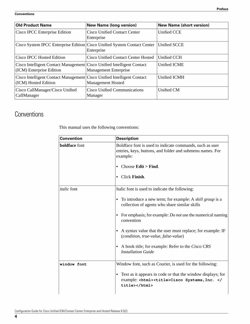
This manual uses the following conventions:
DescriptionConvention
Boldface font is used to indicate commands, such as userentries, keys, buttons, and folder and submenu names. Forexample:
boldface font
• Choose Edit > Find.
• Click Finish.
Italic font is used to indicate the following:italic font
• To introduce a new term; for example: A skill group is acollection of agents who share similar skills
• For emphasis; for example: Do not use the numerical namingconvention
• A syntax value that the user must replace; for example: IF(condition, true-value, false-value)
• A book title; for example: Refer to the Cisco CRSInstallation Guide
Window font, such as Courier, is used for the following:window font
• Text as it appears in code or that the window displays; forexample: <html><title>Cisco Systems,Inc. </title></html>
Configuration Guide for Cisco Unified ICM/Contact Center Enterprise and Hosted Release 8.5(2)
4
Preface
Conventions
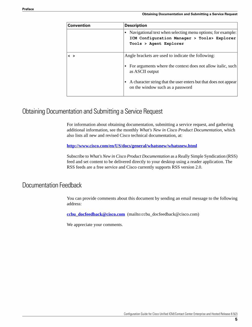
DescriptionConvention
• Navigational text when selecting menu options; for example:ICM Configuration Manager > Tools> Explorer
Tools > Agent Explorer
Angle brackets are used to indicate the following:< >
• For arguments where the context does not allow italic, suchas ASCII output
• A character string that the user enters but that does not appearon the window such as a password
Obtaining Documentation and Submitting a Service Request
For information about obtaining documentation, submitting a service request, and gatheringadditional information, see the monthly What's New in Cisco Product Documentation, whichalso lists all new and revised Cisco technical documentation, at:
http://www.cisco.com/en/US/docs/general/whatsnew/whatsnew.html
Subscribe to What's New in Cisco Product Documentation as a Really Simple Syndication (RSS)feed and set content to be delivered directly to your desktop using a reader application. TheRSS feeds are a free service and Cisco currently supports RSS version 2.0.
Documentation Feedback
You can provide comments about this document by sending an email message to the followingaddress:
[email protected] (mailto:[email protected])
We appreciate your comments.
Configuration Guide for Cisco Unified ICM/Contact Center Enterprise and Hosted Release 8.5(2)
5
Preface
Obtaining Documentation and Submitting a Service Request

Configuration Guide for Cisco Unified ICM/Contact Center Enterprise and Hosted Release 8.5(2)
6
Preface
Documentation Feedback
Configuration OverviewThis chapter provides the following information:
• An introduction to the system software and its components
• An introduction to the Administration Data Server Group and Administration Client Grouptools
• A summary of system management tasks
This chapter contains the following topics:
• Software Overview, page 7• Configuration Management, page 9• Script Management, page 9
Software Overview
This section provides an overview of the following:
• Cisco Unified Intelligent Contact Management (Unified ICM) software (page 7)
• Cisco Unified Contact Center Enterprise (Unified CCE) solution (page 8)
Cisco Unified Intelligent Contact Management Overview
Unified ICM provides enterprise-wide distribution of multi-channel contacts (inbound/outboundtelephone calls, Web collaboration requests, email messages, chat requests) across geographicallyseparated contact centers. Unified ICM is an open standards-based solution with capabilities
Configuration Guide for Cisco Unified ICM/Contact Center Enterprise and Hosted Release 8.5(2)
7
Chapter 1

that include routing, queuing, monitoring, and fault tolerance. Unified ICM forms the basis forthe Cisco Customer Contact Suite.
The system software functions across environments as well as across channels.
The system software functions in the older environment of telephone calls delivered over timedivision multiplexing (TDM) line, of hardware ACDs and IVRs, and of call centers centralizedaround the hardware. The system software can route calls for a single 800 number or for severaldifferent numbers. The system software reads information about each incoming call from thepublic network, determines the best destination for that call, and returns information to thepublic network instructing it where to route the call. This is known as call-by-call routing.
The system software makes routing decisions by executing scripts that can easily be modified.These scripts can use real-time information about activity at the contact centers to find thedestination that is best able to handle the call. You can monitor how the system is handling callsand can make changes to the scripts when needed.
The system software functions in the newer environment of multi-channel contacts deliveredthrough IP connections of software ACDs and IVRs, and of contact centers that can be asdecentralized as the Internet or as centralized as business practices—not hardwarenecessities—require them to be.
The system software functions in the mixed transition environment that involves all of thepreceding factors.
See Also
For detailed information about Unified ICM, see the Pre-installation Planning Guide for CiscoUnified ICM Enterprise and Hosted and the Administration Guide for Cisco Unified ICM/ContactCenter Enterprise & Hosted.
Cisco Unified Contact Center Enterprise Overview
Cisco Unified Contact Center Enterprise (Unified CCE) delivers intelligent contact routing, calltreatment, network-to-desktop computer telephony integration (CTI), and multichannel contactmanagement over an IP infrastructure. It combines multichannel automatic call distributor(ACD) functionality with IP telephony in a unified solution, enabling your company to rapidlydeploy a distributed contact center infrastructure.
Unified CCE provides:
• Segmentation of customers, and monitoring of resource availability
• Delivery of each contact to the most appropriate resource anywhere in the enterprise
• Comprehensive customer profiles using contact-related data, such as dialed number, andcalling line ID
• Routing to the most appropriate resource to meet customer needs based on real-time conditions(such as agent skills, availability, and queue lengths)
Configuration Guide for Cisco Unified ICM/Contact Center Enterprise and Hosted Release 8.5(2)
8
Chapter 1: Configuration Overview
Software Overview
• Presence integration to increase caller satisfaction through improved agent performance, andknowledge-worker expertise
Unified CCE allows you to smoothly integrate inbound and outbound voice applications withInternet applications such as real-time chat, web collaboration, and email. This integrationenables a single agent to support multiple interactions simultaneously regardless of whichcommunications channel the customer has chosen. Because each interaction is unique and mayrequire individualized service, Cisco provides contact center solutions to manage customerinteractions based on almost any contact attribute.
See Also
For detailed information about Unified CCE, see the Installation and Configuration Guide forCisco Unified Contact Center Enterprise & Hosted and the Administration Guide for CiscoUnified Contact Center Enterprise & Hosted.
Configuration Management
Unified ICM configuration information is permanently stored in the Central Controller database.The system software configuration consists of hardware entities, call targets, announcements,routes, dialed numbers, and regions. Use the Unified ICM/CCE/CCH Configuration Manager(referred to as the “Configuration Manager” in this guide) tools to create and modify configurationdata. When you apply a change in the Configuration Manager, it is immediately applied to thecentral database.
To get started setting up and maintaining your configuration, see Chapter 3, “The ConfigurationManager (page 29).”
Script Management
After you have set up your configuration, you can write routing scripts and administrative scripts:
• A routing script processes a call routing request from a routing client and determines the bestdestination for that call. The system software then passes a label associated with the destinationback to the routing client.
• An administrative script runs periodically to perform a task, such as setting variables.
Use the Script Editor to create, maintain, and monitor scripts.
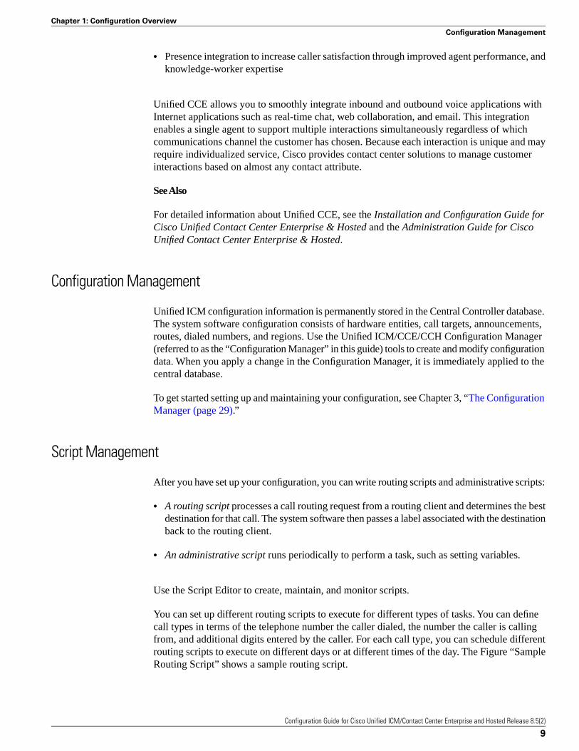
You can set up different routing scripts to execute for different types of tasks. You can definecall types in terms of the telephone number the caller dialed, the number the caller is callingfrom, and additional digits entered by the caller. For each call type, you can schedule differentrouting scripts to execute on different days or at different times of the day. The Figure “SampleRouting Script” shows a sample routing script.
Configuration Guide for Cisco Unified ICM/Contact Center Enterprise and Hosted Release 8.5(2)
9
Chapter 1: Configuration Overview
Configuration Management
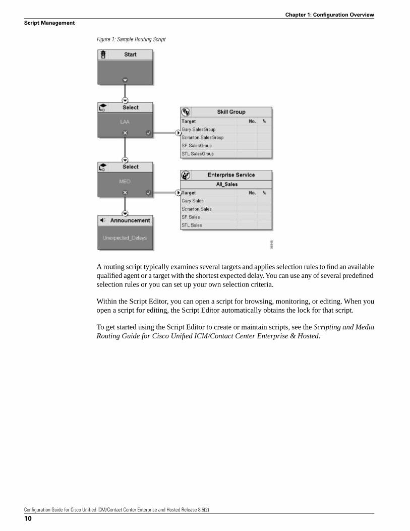
Figure 1: Sample Routing Script
A routing script typically examines several targets and applies selection rules to find an availablequalified agent or a target with the shortest expected delay. You can use any of several predefinedselection rules or you can set up your own selection criteria.
Within the Script Editor, you can open a script for browsing, monitoring, or editing. When youopen a script for editing, the Script Editor automatically obtains the lock for that script.
To get started using the Script Editor to create or maintain scripts, see the Scripting and MediaRouting Guide for Cisco Unified ICM/Contact Center Enterprise & Hosted.
Configuration Guide for Cisco Unified ICM/Contact Center Enterprise and Hosted Release 8.5(2)
10
Chapter 1: Configuration Overview
Script Management

How Routing WorksThis chapter describes in detail the process of routing a call.
The chapter includes the following topics:
• An overview of the routing process
• A description of routing requests and routing clients
• Information about how calls arrive at targets
• An overview of translation routes
• The importance of timeouts and thresholds
Understanding this process will help you set up the configuration of your system software andcreate effective scripts.
This chapter contains the following topics:
• The Routing Process, page 11• Steps in the Routing Process, page 12• Routing Requests, page 13• Targets, page 13• Translation Routes, page 19• Timeouts and Thresholds, page 20• Configuring Service Levels, page 23
The Routing Process
To properly route calls, three independent systems must work together:
Configuration Guide for Cisco Unified ICM/Contact Center Enterprise and Hosted Release 8.5(2)
11
Chapter 2

• The routing client
• The system software
• The peripheral that ultimately receives the call
The routing client requests a route from the system software, receives a response, and deliversthe call to the specified destination.
The system software receives routing requests and determines the appropriate destination forthe call. The destination is an announcement (which is played by the routing client), a scheduledtarget, or a specific target at a peripheral (represented by a trunk group and DNIS).
A peripheral is a switch at a call center, such as an ACD, a PBX, or Unified CM. The peripheralcompletes the routing by dispatching the call to the specific target determined by the systemsoftware.
Steps in the Routing Process
The process of routing a call consists of the following steps:
Step 1 A routing client requests a route from the system software.
Step 2 The system software, using information supplied by the routing client, categorizes the requestas a specific call type.
Step 3 The system software executes a routing script scheduled for the call type to find a destinationfor the call. The destination can be a routing label, an announcement, or a skill target: a service,skill group, or agent. (If the script fails to find a destination, the system software uses a defaultdestination based on the dialed number.)
Step 4 If: the destination is an announcement, scheduled target, or skill target
Then: the system software maps that destination to a routing label.
A routing label is a character string value that the routing client maps to a destination trunkgroup and, optionally, to a Dialed Number Identification Service (DNIS) value for the call.
Step 5 The system software passes the routing label back to the routing client.
Step 6 The routing client interprets the label to find the destination.
Step 7 The routing client dispatches the call to the destination (with the appropriate DNIS value, ifany).
Step 8 If: the call is sent to a peripheral
Then: the peripheral must determine the specific target for which the call is intended
Configuration Guide for Cisco Unified ICM/Contact Center Enterprise and Hosted Release 8.5(2)
12
Chapter 2: How Routing Works
The Routing Process
The peripheral typically makes this determination based on the trunk group on which the callarrived and, optionally, the DNIS value sent with the call. The peripheral then completes therouting by dispatching the call appropriately.
The following sections describe the process in detail.
Routing Requests
The system software receives routing requests from routing clients, where the type is either thespecific IXC (for example, AT&T, MCI, or Sprint) or the specific type of the peripheral (forexample, a VRU or a specific type of ACD).
Routing clients send messages to the system software. One type of message is a route request.In this case, given a call, the routing client asks the system software for a destination, or route,for that call. If the routing client is an IXC, a route request is the only type of message that itsends.
Routing requests are of two types: Pre-Routing and Post-Routing. A Pre-Routing request is sentby an IXC to determine the initial destination for a call. A Post-Routing request is sent by theperipheral that receives the call to either refine the original route or to redirect the call.
A routing request includes the following information about the call to be routed:
• Dialed Number (DN). The number the caller dialed.
• Calling Line ID (CLID). The caller’s billing telephone number. This value is also referredto as Automatic Number Identification or ANI.
• Caller-Entered Digits (CED). Digits the caller entered on a touch-tone phone in responseto prompts.
Post-Routing messages vary depending on the type of the peripheral.
Targets
A target is the destination for a call. The target can be either a label, an announcement definedby the routing client, or a target at a peripheral.
On a high level, a target at the peripheral is a service, skill group, or individual agent that thesystem software selects to handle the call. This is called the skill target. Regardless of the specificskill target, every call routed by the system software must also be associated with a service. Thecombination of a skill target and a service is a route.
On a low level, a target represents a network trunk group at the peripheral and, optionally, aDialed Number Identification Service (DNIS) value. The routing client uses this type of target,called a peripheral target, to route the call.
Configuration Guide for Cisco Unified ICM/Contact Center Enterprise and Hosted Release 8.5(2)
13
Chapter 2: How Routing Works
Routing Requests
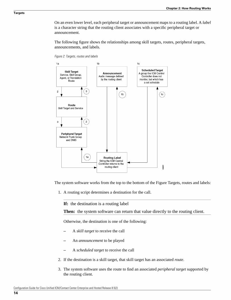
On an even lower level, each peripheral target or announcement maps to a routing label. A labelis a character string that the routing client associates with a specific peripheral target orannouncement.
The following figure shows the relationships among skill targets, routes, peripheral targets,announcements, and labels.
Figure 2: Targets, routes and labels
The system software works from the top to the bottom of the Figure Targets, routes and labels:
1. A routing script determines a destination for the call.
If: the destination is a routing label
Then: the system software can return that value directly to the routing client.
Otherwise, the destination is one of the following:
– A skill target to receive the call
– An announcement to be played
– A scheduled target to receive the call
2. If the destination is a skill target, that skill target has an associated route.
3. The system software uses the route to find an associated peripheral target supported bythe routing client.
Configuration Guide for Cisco Unified ICM/Contact Center Enterprise and Hosted Release 8.5(2)
14
Chapter 2: How Routing Works
Targets
4. The peripheral target is associated with a label. The system software returns that label tothe routing client. If the destination is an announcement, the system software only needsto find the label associated with that announcement and return the label to the routingclient.
The routing client processing depends on the type of the label. Some labels instruct the routingclient to take a special action: playing a busy signal for the caller, playing an unanswered ringfor the caller, or making a special query.
For normal labels, the routing client converts the label to an announcement, scheduled target,or peripheral target by working up from the bottom of the “Targets, Routes and Labels” figure.
1. The routing client receives a label from the system software in response to its route request.
It translates that label into one of the following:
– A peripheral target
– An announcement
– A scheduled target
– An unrouted task that gets routed to a local agent
If: the result is an announcement
Then: it plays the announcement for the caller.
If: the result is a scheduled target
Then: it delivers the call to that target.
2. If: the result is a peripheral target
Then: the routing client delivers the call to the specified network trunk group atthe peripheral and sends the specified DNIS value, if any, with it.
3. The peripheral itself must then recognize the network trunk group and DNIS for the callas it arrives and determine the associated service and skill target. The peripheral thencompletes the process by locating the appropriate agent to handle the call.
Cisco Unified Intelligent Contact Management Enterprise System Processing
The “Unified ICME Route Request Processing (page 16)” figure summarizes how the systemsoftware processes a route request.
Configuration Guide for Cisco Unified ICM/Contact Center Enterprise and Hosted Release 8.5(2)
15
Chapter 2: How Routing Works
Targets
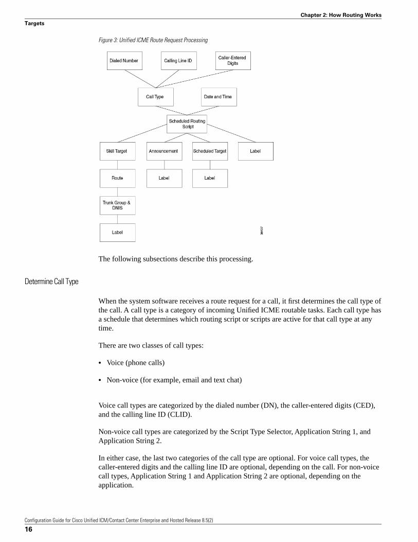
Figure 3: Unified ICME Route Request Processing
The following subsections describe this processing.
Determine Call Type
When the system software receives a route request for a call, it first determines the call type ofthe call. A call type is a category of incoming Unified ICME routable tasks. Each call type hasa schedule that determines which routing script or scripts are active for that call type at anytime.
There are two classes of call types:
• Voice (phone calls)
• Non-voice (for example, email and text chat)
Voice call types are categorized by the dialed number (DN), the caller-entered digits (CED),and the calling line ID (CLID).
Non-voice call types are categorized by the Script Type Selector, Application String 1, andApplication String 2.
In either case, the last two categories of the call type are optional. For voice call types, thecaller-entered digits and the calling line ID are optional, depending on the call. For non-voicecall types, Application String 1 and Application String 2 are optional, depending on theapplication.
Configuration Guide for Cisco Unified ICM/Contact Center Enterprise and Hosted Release 8.5(2)
16
Chapter 2: How Routing Works
Targets
While chat sessions and blended collaboration are different from email and require call variables,the call variables are not part of the call type definition.
For example, you might define three call types to correspond to three sales regions within thecountry. You might have a network prompt that lets the caller enter 1 for sales, 2 for support,and 3 for information. If a call arrives for the dialed number 800.486.0029, with a CLID fromthe 403 (San Jose region) area code, and the caller enters 1 (sales) in response to the prompt,that call is classified as Western Sales.
If another call arrives with the same dialed number, but with a CLID from the 212 (New YorkCity) area code, and the caller-entered digit 1, that call is classified as Eastern Sales.
You can define a general default call type and a specific default call type for each routing client.If the call qualifiers do not map to a specific call type, the system software uses a default calltype defined for the routing client. If no default call type is defined for the routing client, thesystem software uses the general default call type.
Execute Script
Each call type has specific routing scripts scheduled for different times of day and differentdays of the year. The system software finds the script currently scheduled for the call type andexecutes it. If that script fails to find a suitable destination (that is, a label, announcement, orskill target) for the call, then the system software uses a default target associated with the DialedNumber value.
If the system software finds an announcement or scheduled target for the call, then it canimmediately resolve that to a label to return to the routing client. If the system software findsa skill target for the call, it must perform a few extra steps before it finds a label.
Determine Route
If the system software finds a skill target for the call, that target has an associated route. Youspecify the route when you set up the target within the routing script. A route represents thecombination of a skill target and a service. That is, a route represents the destination for a calland the type of service to be provided to the caller. Every call routed to a peripheral must havean associated service.
For example, the skill target for a call might be the skill group Denver.PostSales and theassociated service might be Denver.TechSupport. Another call might also be routed to theDenver.PostSales group with the associated service Denver.Upgrades.
Note: If the destination is itself a service, for example Chicago.Sales, then the associated servicemust also be Chicago.Sales. To associate a service skill target with a route for a different servicewould skew the statistics for those services.
Determine Trunk Group and DNIS
Once it has determined a route for a call, the system software finds an associated peripheraltarget (trunk group and DNIS). It is possible to have several peripheral targets associated withthe same route, but typically only one of those targets is valid for the routing client. For example,
Configuration Guide for Cisco Unified ICM/Contact Center Enterprise and Hosted Release 8.5(2)
17
Chapter 2: How Routing Works
Targets
if you have switched access lines, two IXCs could direct calls to the same trunk group andDNIS, but each requires a different label value for that target. Therefore, you need to definetwo separate peripheral targets for the route. If more than one peripheral target is associatedwith the route, the system software chooses the first peripheral target that maps to a valid labelfor the routing client.
Determine Label
Each peripheral target, scheduled target, or announcement maps to one or more labels. Thesystem software finds the first label that is valid for the routing client and dialed number andreturns that label to the routing client. It is then up to the routing client to interpret the label.
Default Label
It is possible that the system software might fail to find a call type for a route request. Also, thesystem software may execute the script currently scheduled for a call type and fail to find adestination for the call. In these cases, it uses a default label that is defined for the dialed number.If no default label is defined for the dialed number, the system software returns an error to therouting client.
The routing client itself also has some default action defined. When you set up each routingclient you can specify the maximum time that client can wait for a response to a routing request.If the system software has not returned a destination for the call before the time limit is reached,or if the system software returns an error, the routing client performs its own default action.
For more information about timeout limits, see the “Timeouts and Thresholds (page 11)” section.
Routing Client Processing
The routing client begins by requesting a route for a call from the system software. The systemsoftware processes the request as described in the preceding section and returns a label to therouting client.
The routing client has its own internal mappings for labels to announcements, scheduled targets,and peripheral targets.
It uses these mappings to interpret the label from the system software:
• Busy. Routing client plays a busy signal for the caller.
• Ring. Routing client plays an unanswered ring for the caller.
• Normal and the label maps to an announcement. Routing client plays the announcementfor the caller.
• Normal and the label maps to a scheduled target. Routing client delivers the call to thattarget.
Configuration Guide for Cisco Unified ICM/Contact Center Enterprise and Hosted Release 8.5(2)
18
Chapter 2: How Routing Works
Targets
• Normal or DNIS Override and the label maps to a peripheral target (that is, a trunk groupand a DNIS). Routing client delivers the call and the specified DNIS value to that trunk group.The peripheral then has responsibility for dispatching the call to the appropriate skill target.
The Peripheral Processing
When a peripheral receives a call, it determines the trunk group on which the call arrived andthe DNIS value, if any, associated with it. The peripheral must be programmed to map thesevalues to the same service and skill target determined by the system software.
The peripheral, acting as a routing client, can also send a routing request to the system software.
Translation Routes
Sometimes you want to send additional information along with the call to a skill target.Translation routes allow you to do that.
A translation route is a temporary destination for a call. When the system software returns atranslation route label to the routing client, it also sends a message directly to the PeripheralGateway (PG) at the targeted peripheral. This message alerts the PG that a call will be arrivingthat requires route translation.
The message contains the following information:
• The trunk group on which the call will arrive and the DNIS value associated with it.
• A label to be used by the PG to determine the ultimate skill target of the call. This is a labelthat the PG can interpret to find the correct destination.
• Instructions for further processing to be performed by the PG. This further processing mightinclude, for example, looking up an account number in a database.
When the peripheral sees the call arrive on the specified trunk group and with the specifiedDNIS value, it passes this information to the PG. The PG then combines it with the informationit has received from the system software. It then sends the call along with this information tothe skill target specified by the label it received. At the same time, the peripheral might, forexample, send a message to a host computer that controls the display on the agent’s workstation.This allows data, such as the callers account information, to be displayed on the screen whenthe call arrives. The PG coordinates communication among the network, the peripheral, and thecomputer application that controls the display.
To set up a translation route, you must do the following:
• Set up a translation route associated with the peripheral. You do not need a separate translationroute for each possible skill target at the site, but you need at least one for each peripheralthat performs translation routing.
Configuration Guide for Cisco Unified ICM/Contact Center Enterprise and Hosted Release 8.5(2)
19
Chapter 2: How Routing Works
Translation Routes
• Set up one or more routes and associated peripheral targets for the translation route. Typically,all peripheral targets for a translation route refer to the same trunk group, but with differentDNIS values.
• Set up a label for the original routing client for the call to access each of the peripheral targetsassociated with the translation route. For example, if the routing client is an interexchangecarrier (IXC), you must set up a label to the targets with the IXC. This allows the call to beinitially sent to the translation route at the peripheral.
• For each peripheral target that you want to be able to ultimately access via a translation route,set a label with the peripheral as the routing client. For example, you might want to be ableto send calls to the Atlanta.Support skill group through a translation route. To do this, youmust configure a label for that skill group with the Atlanta peripheral as the routing client.This allows the peripheral to determine the ultimate destination for the call.
• To display data on the agent’s workstation when the call arrives, you must configure theperipheral to inform the PG which agent is receiving the call.
Timeouts and Thresholds
In setting up your configuration, you need to specify several timeout and timing threshold values.
For routing clients, you must specify the maximum time the system software can spend beforeresponding to each routing request. You must also specify the maximum time for the routingclient to wait for a response before it stops sending new requests to the system software.
For each service at a peripheral, you must specify your goal for the maximum time a caller mustwait before the call is answered. The system software uses this value in calculating the servicelevel.
You can specify how to count abandoned calls in the service level calculation. You can alsospecify the minimum time a call must be in the queue before it can be considered abandoned.
For specific information about configuring routing clients, peripherals, and services, see Chapters4 through 7.
Routing Clients
In some cases, a routing client might be unable to receive routing responses from the systemsoftware. Sometimes this affects only a single request, but other times the routing client losescontact with the system software for longer periods. You can specify the amount of time for therouting client to wait before giving up on a single request and the amount of time to wait beforeit stops sending any requests to the system software.
Timeout Threshold
The maximum time (in milliseconds) the routing client can wait for a response to a routingrequest. The NIC sends a default response before this threshold.
Configuration Guide for Cisco Unified ICM/Contact Center Enterprise and Hosted Release 8.5(2)
20
Chapter 2: How Routing Works
Timeouts and Thresholds

Late Threshold
A threshold value (in milliseconds) for classifying responses as late. Any response that exceedsthis threshold is considered late even if it does not exceed the Timeout Threshold.
Timeout Limit
The system software is designed to be a highly reliable system. Distributed duplicated hardwareand software fault-tolerance ensure very high availability. However, the NIC uses a timeoutlimit to provide a safety net to ensure that your calls continue to be routed even if the systemsoftware were to become completely unavailable. If the routing client receives no responsesfrom the system software within the timeout limit (and a minimum number of requests havebeen made), it stops sending requests to the system software. You can set the minimum numberof requests that must be made (the consecutive timeout limit) when you set up the NIC software.The default is 10.
When a routing request first exceeds the timeout threshold, the NIC for the routing client startsa timer. If the timer reaches the timeout limit before the routing client receives any on-timerouting responses from the system software, then the NIC tells the routing client to stop sendingrouting requests to the system software. An on-time response is a response within the timeoutthreshold. You can specify the timeout limit in seconds. For example, for AT&T ICP connections,set the timeout limit to 10 seconds.
Abandoned Call Wait Time
When a call is delivered to a peripheral, the caller might be placed in a queue waiting for anagent to become available. Normally, if the caller hangs up before being connected with anagent, the call is considered abandoned. A high number of abandoned calls might mean thatyou are losing business because callers have too long a wait.
However, if a caller hangs up almost immediately after being placed in a queue, you might notwant to count that as an abandoned call. In these cases, caller impatience or excessive queuetimes are not the problem; the caller probably hung up for another reason. Tracking these asabandoned calls can be misleading.
Therefore, you can specify a minimum amount of time that a caller must wait before the callcan be considered abandoned. This value is called the abandoned call wait time. You can setthis value for each peripheral. A typical value might be 10 seconds. This would mean that if thecaller hangs up in the first 10 seconds, the call is not considered abandoned, nor is it countedas a call offered. If the caller waits at least 10 seconds and then hangs up, the call is counted asboth offered and abandoned. (In the real-time data, a call is counted as offered as soon as itarrives at the peripheral. Therefore, a short call might appear as a call offered in the real-timedata, but is not counted as offered in the historical data.)
Configuration Guide for Cisco Unified ICM/Contact Center Enterprise and Hosted Release 8.5(2)
21
Chapter 2: How Routing Works
Timeouts and Thresholds
Service Level
Service level is a measure of how well you are meeting your goals for answering calls. For eachservice, you can set a goal for the maximum time a caller spends in a queue before connectingto an agent. This value is the service level threshold. The service level is usually expressed asthe percentage of calls that are answered within the threshold.
To calculate the service level for a period of time, the system software determines the numberof calls that have had a service level event within that period.
A service level event occurs when one of three things happens to a call:
• The call is answered within the service level threshold.
• The call is abandoned within the service level threshold.
• The call reaches the service level threshold without being answered or abandoned.
All calls that have a service level event within a specified period are considered as service levelcalls offered for that period. This differs from the offered value for a simple call, which countseach call at the time it is first offered to the service.
Service Level Threshold
The service level threshold is the number of seconds you set as a goal for connecting a call withan agent. When you set up a peripheral, you can specify a default service level threshold for allservices associated with that peripheral. When you set up each service, you can choose to eitheruse the default threshold set for the peripheral or specify a threshold for the service itself in theService Level Threshold field. If you do not specify a service level threshold for an individualservice, the default threshold you specified for the peripheral is used. Typically, you must setthese values to match the service level thresholds the peripheral uses.
Service Level Types
Different peripheral types use slightly different formulas to calculate service level. The systemsoftware provides a uniform calculation across all peripherals. This allows you to apply uniformmetrics and performance goals across all peripherals. However, the system software also tracksthe service level as calculated by the peripheral itself. This is called the peripheral service level.You can use this value, for example, to continue to compare performance to historical norms.
Some peripherals let you select one of several types of service level calculation. You can specifywhich of these types of service level you want the system software to track.
The uniform service level calculation performed by the system software can be done in any ofthree ways:
• Abandoned calls ignored. The number of calls answered within the threshold divided bythe number of calls with a service level event minus the number of calls that were abandoned
Configuration Guide for Cisco Unified ICM/Contact Center Enterprise and Hosted Release 8.5(2)
22
Chapter 2: How Routing Works
Timeouts and Thresholds
before exceeding the service level threshold. Calls abandoned before the service level thresholdexpired are removed from this calculation.
• Abandoned calls negatively impact service level. The number of calls answered within thethreshold divided by the number of calls with a service level event. This calculation treatsthese abandoned calls as if they exceeded the threshold.
• Abandoned calls positively impact service level. The number of calls answered within thethreshold plus the number of calls abandoned within the threshold, all divided by the numberof calls that had a service level event. This calculation treats these abandoned calls as thoughthey were answered within the threshold.
The following example illustrates these different ways of calculating service level.
Example Service Level Calculations
Call Counts
Answered within service level threshold: 70
Abandoned within service level threshold: 10
Exceeded service level threshold: 20
Total service level events: 100
Service Level Calculations
Abandoned calls ignored: 70 / (100 - 10) = 77.7%
Abandoned calls negatively impact: 70 / 100 = 70.0%
Abandoned calls positively impact: (70 + 10) / 100 = 80.0%
The value of the Service Level Type field for the service determines how the system softwaretreats abandoned calls. You set this value when you configure the service.
Configuring Service Levels
Service Level is set in six configurable windows in Configuration Manager, which you candefine in different ways depending on the kind of information you want it to provide.
• System Level (page 24)
• Call Types (page 24)
• Media Routing Domain (page 26)
• Peripheral (page 27)
Configuration Guide for Cisco Unified ICM/Contact Center Enterprise and Hosted Release 8.5(2)
23
Chapter 2: How Routing Works
Configuring Service Levels
• Skill Group (page 27)
• VRU (page 28)
Configuring the System Information Service Level for Call Types
Service Levels are set at the System Information level for all call types. To view or change thedefault system-level settings for all Call Types:
Step 1 In the Configuration Manager, select Tools > Miscellaneous Tools > System Information.
Step 2 Specify a value for Service level threshold in seconds.
The default is 20 seconds.
Step 3 Select the Service level type.
Options are Abandoned Calls have Negative Impact, Abandoned Calls have Positive Impact,and Ignore Abandoned Calls.
The default is Ignore Abandoned Calls.
Step 4 Click Save.
Configuring the Service Levels for Specific Call Types
To configure Service Levels for specific Call Types, which override the System Informationsettings:
Step 1 In the Configuration Manager, select Tools > List Tools > Call Type Lists.
Step 2 Click Retrieve.
Step 3 Select the Call Type whose service level you want to set.
Step 4 For Service level threshold, check the box to the right of the field to override the default fromthe System Information (20 seconds).
Specify a Service level threshold value in seconds for this Call Type.
Step 5 For Service level type, check the box to the right of the field to override the default.
Select from Ignore Abandoned Calls, Abandoned Calls have Negative Impact, and AbandonedCalls have Positive Impact.
Step 6 Click Save.
Configuration Guide for Cisco Unified ICM/Contact Center Enterprise and Hosted Release 8.5(2)
24
Chapter 2: How Routing Works
Configuring Service Levels
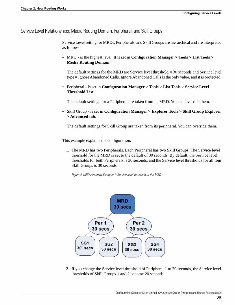
Service Level Relationships: Media Routing Domain, Peripheral, and Skill Groups
Service Level setting for MRDs, Peripherals, and Skill Groups are hierarchical and are interpretedas follows:
• MRD - is the highest level. It is set in Configuration Manager > Tools > List Tools >Media Routing Domain.
The default settings for the MRD are Service level threshold = 30 seconds and Service leveltype = Ignore Abandoned Calls. Ignore Abandoned Calls is the only value, and it is protected.
• Peripheral - is set in Configuration Manager > Tools > List Tools > Service LevelThreshold List.
The default settings for a Peripheral are taken from its MRD. You can override them.
• Skill Group - is set in Configuration Manager > Explorer Tools > Skill Group Explorer> Advanced tab.
The default settings for Skill Group are taken from its peripheral. You can override them.
This example explains the configuration.
1. The MRD has two Peripherals. Each Peripheral has two Skill Groups. The Service levelthreshold for the MRD is set to the default of 30 seconds, By default, the Service levelthresholds for both Peripherals is 30 seconds, and the Service level thresholds for all fourSkill Groups is 30 seconds.
Figure 4: MRD Hierarchy Example 1: Service level threshold at the MRD
2. If you change the Service level threshold of Peripheral 1 to 20 seconds, the Service levelthresholds of Skill Groups 1 and 2 become 20 seconds.
Configuration Guide for Cisco Unified ICM/Contact Center Enterprise and Hosted Release 8.5(2)
25
Chapter 2: How Routing Works
Configuring Service Levels

The Service level thresholds of Skill Groups 3 and 4 remain at 30 seconds.
Figure 5: MRD Hierarchy Example 2: Changing the Peripheral
3. If you want the Service level threshold of Skill Group 1 to be 45 seconds, you canindependently configure Skill Group 1 to have a Service level threshold of 45 seconds.
Figure 6: MRD Hierarchy Example 3: Changing the Skill Group
Configuring the Service Level for the Media Routing Domain
To configure the Service Level settings for the Media Routing Domain:
Step 1 In the Configuration Manager, select Tools > List Tools > Media Routing Domain List.
Step 2 Select the Routing Domain whose service level you want to modify.
Configuration Guide for Cisco Unified ICM/Contact Center Enterprise and Hosted Release 8.5(2)
26
Chapter 2: How Routing Works
Configuring Service Levels
Step 3 Click Retrieve.
Step 4 Select the MRD whose Service level you want to set.
Step 5 Specify a value in seconds for Service level threshold. The default is 30 seconds.
Step 6 Service level type is protected and always shows Ignore Abandoned Calls.
Step 7 Click Save.
Configuring the Service Level for a Peripheral
To configure Service Level settings for a Peripheral:
Step 1 In the Configuration Manager, select Tools > List Tools > Service Level Threshold List.
Step 2 Click Retrieve to populate the list with the Peripherals.
Step 3 Select the Peripheral whose Service Level you want to modify.
Step 4 Specify a value for Service level threshold. The default is inherited from the MRD.
Your options are to:
• Retain the default from the MRD.
• Check the Override MRD default box to unprotect the value and enter a new value in secondsfor the Peripheral Service level threshold.
Step 5 For Service level type, check the box to override the default. Select from Abandoned Calls haveNegative Impact, Abandoned Calls have Positive Impact, and Ignore Abandoned Calls.
For a non-Unified CCE/CCH peripheral and a voice media routing domain, select fromAbandoned Calls have Negative Impact, Abandoned Calls have Positive Impact, and IgnoreAbandoned Calls. For other media routing domains, only Ignore Abandoned Calls, and it isprotected.
Step 6 Click Save.
Configuring the Service Level for Skill Groups
To configure Service Level settings for a Skill Group:
Step 1 In the Configuration Manager, select Explorer Tools > Skill Group Explorer.
Step 2 Click Retrieve.
Configuration Guide for Cisco Unified ICM/Contact Center Enterprise and Hosted Release 8.5(2)
27
Chapter 2: How Routing Works
Configuring Service Levels
Step 3 Select the Skill Group and click the Advanced tab.
Step 4 Service level threshold defaults to that of the Peripheral.
Your options are to:
• Keep the Service level threshold setting of the Peripheral.
• Check the Override Peripheral default box to unprotect the value and enter a new value inseconds for the Skill Group Service level threshold.
Step 5 Service level type defaults to that of the Peripheral.
Your options are to:
• Keep the setting of the Peripheral.
• From the dropdown, change to Abandoned Calls have Negative Impact, Abandoned Callshave Positive Impact, or Ignore Abandoned Calls.
Step 6 Click Save.
Configuring the Service Level for an Aspect VRU
To configure Service Level settings for an Aspect VRU:
Step 1 In the Configuration Manager, select Explorer Tools > PG Explorer.
Step 2 Click Retrieve.
Step 3 Select and expand the PG.
Step 4 Select the peripheral and click the Peripheral tab.
For all peripherals except Aspect, the Peripheral Service Level Type field is protected and showsCalculated by Call Center.
For Aspect, choose the type of calculation to be performed by default. You can override thedefault for each individual service.
Configuration Guide for Cisco Unified ICM/Contact Center Enterprise and Hosted Release 8.5(2)
28
Chapter 2: How Routing Works
Configuring Service Levels
The Configuration ManagerAfter you have installed Cisco Unified Intelligent Contact Management (Unified ICM) andhave it running, use the Configuration Manager to view and update the configuration informationin the Unified ICM database. The configuration information describes the people, groups, anddevices that are part of your enterprise.
For example, use the Configuration Manager to specify:
• The devices in your system and the clients they serve
Which includes
– The peripherals at your contact centers
– The routing clients served by your system
• Targets at the peripherals to which the system software can direct calls
Which includes
– Trunks and trunk groups connected to peripherals
– Skill targets associated with each peripheral: agents, skill groups, services, and translationroutes
– Information used by scripts to organize call requests and direct calls to targets, includingcall types, regions, prefixes, and dialed numbers
– Targets understood by the routing client, including announcements, peripheral targets,and routing labels
– The associations among routing labels, routes, peripheral targets, and skill targets
• Enterprise services and enterprise skill groups as a combination of individual services andgroups from different contact centers
Configuration Guide for Cisco Unified ICM/Contact Center Enterprise and Hosted Release 8.5(2)
29
Chapter 3
This chapter contains the following topics:
• Accessing the Configuration Manager, page 30• Using the Configuration Manager, page 30• Online Help, page 31• Configuration Manager Tools, page 32
Accessing the Configuration Manager
To access the Configuration Manager:
• Double-click the Unified CCE Administration Tools folder icon, then double-click theConfiguration Manager icon.
-or-
• From the Start menu, select All Programs > Cisco Unified CCE Tools > AdministrationTools > Configuration Manager.
Using the Configuration Manager
When you start the Configuration Manager, the Configuration Manager window appears. The“Configuration Manager (page 31)” figure shows the window with the top-level directoriesdisplayed for all its menus.
The Configuration Manager lets you view and update the configuration information in theUnified ICM database. The configuration information describes the people, groups, and devicesthat are part of your enterprise.
To set up the configuration of a new system when you are a new user, follow the steps in theStep by Step Configuration selection list in the menu bar.
Use the tools in the Telephony Contact Center Configuration menu in the order listed, to configurefirst the Network Interface Controllers (NICs), then the peripherals, and so on. After youconfigure the system software for your telephony contact center, you can configure the softwarefor multi-media applications.
The tools in the MultiMedia Contact Center Configuration menu are also in the order in whichyou might use them. For example: you must have a media class before you can create a mediarouting domain for that class. And you must have an application instance before you can specifythe path to that application.
To ...
• Access the configuration tools according to the menu selections of the former Configure ICMtool, in the menu, select Configure ICM.
• Access all the tools you can use in the Configuration Manager, in the menu bar, select Tools.
Configuration Guide for Cisco Unified ICM/Contact Center Enterprise and Hosted Release 8.5(2)
30
Chapter 3: The Configuration Manager
Accessing the Configuration Manager
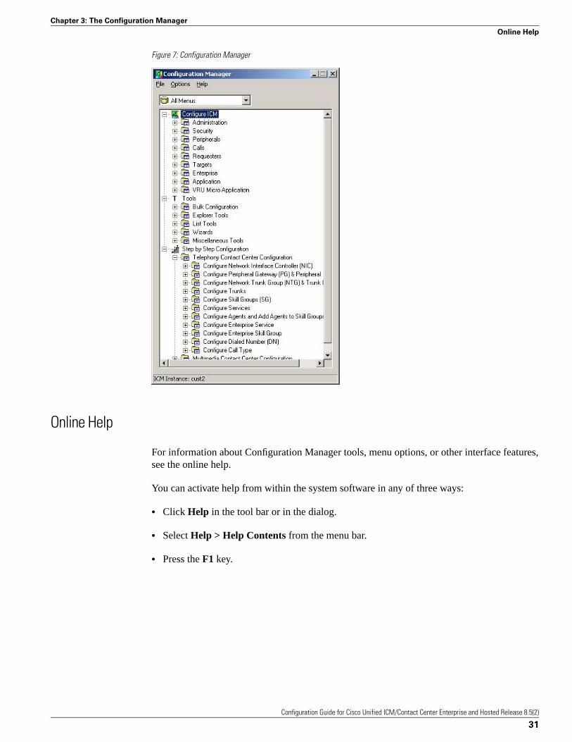
Figure 7: Configuration Manager
Online Help
For information about Configuration Manager tools, menu options, or other interface features,see the online help.
You can activate help from within the system software in any of three ways:
• Click Help in the tool bar or in the dialog.
• Select Help > Help Contents from the menu bar.
• Press the F1 key.
Configuration Guide for Cisco Unified ICM/Contact Center Enterprise and Hosted Release 8.5(2)
31
Chapter 3: The Configuration Manager
Online Help
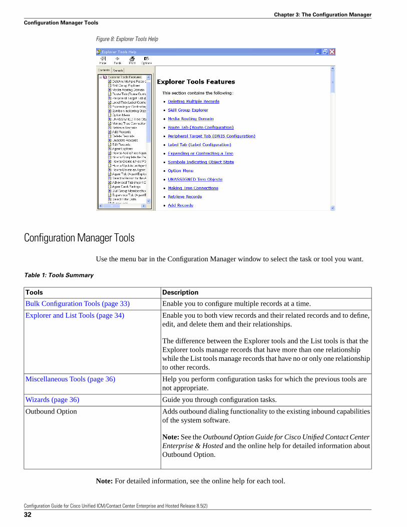
Figure 8: Explorer Tools Help
Configuration Manager Tools
Use the menu bar in the Configuration Manager window to select the task or tool you want.
Table 1: Tools Summary
DescriptionTools
Enable you to configure multiple records at a time.Bulk Configuration Tools (page 33)
Enable you to both view records and their related records and to define,edit, and delete them and their relationships.
Explorer and List Tools (page 34)
The difference between the Explorer tools and the List tools is that theExplorer tools manage records that have more than one relationshipwhile the List tools manage records that have no or only one relationshipto other records.
Help you perform configuration tasks for which the previous tools arenot appropriate.
Miscellaneous Tools (page 36)
Guide you through configuration tasks.Wizards (page 36)
Adds outbound dialing functionality to the existing inbound capabilitiesof the system software.
Outbound Option
Note: See the Outbound Option Guide for Cisco Unified Contact CenterEnterprise & Hosted and the online help for detailed information aboutOutbound Option.
Note: For detailed information, see the online help for each tool.
Configuration Guide for Cisco Unified ICM/Contact Center Enterprise and Hosted Release 8.5(2)
32
Chapter 3: The Configuration Manager
Configuration Manager Tools
Bulk Configuration Tools
Use the Configuration Manager Bulk Configuration tools to configure multiple records at atime. For information about how to use these tools, see Chapter 4, “Configuring Multiple Recordsat a Time (page 51).”
The Bulk Configuration tools enable you to bulk configure the following individual databasetable records.
The tools are named for the records they manage:
• Agents
• Call types
• Dialed number plans
• Dialed numbers
• Device targets
• Labels
• Network trunk groups
• Network VRU scripts
• Peripheral targets
• Person bulk tool
• Regions
• Region prefixes
• Routes
• Trunks
• Trunk groups
• Scheduled targets
• Services
• Skill groups
• VRU port maps
Note: See the online help for each tool for detailed information.
Configuration Guide for Cisco Unified ICM/Contact Center Enterprise and Hosted Release 8.5(2)
33
Chapter 3: The Configuration Manager
Configuration Manager Tools

Explorer and List Tools
Use the Configuration Manager Explorer and List tools to configure and manage individualdatabase records.
Explorer Tools
Use the Explorer tools to configure and manage database records that have hierarchicalrelationships to other records. In this way, at one time, you can see and update both the individualrecords and their relationships. You can configure and manage the following records with theExplorer tools.
The tools are named for the type of records they manage:
• Agent Explorer
• Announcement Explorer
• Database Lookup Explorer
• Device Target Explorer
• ICM Instance Explorer
• Network VRU Explorer
• Network Trunk Group Explorer
• NIC Explorer
• PG Explorer
• Region Explorer
• Scheduled Target Explorer
• Service Explorer
• Service Array Explorer
• Skill Group Explorer
• Translation Route Explorer
See Also
For detailed information see the online help for each tool.
Configuration Guide for Cisco Unified ICM/Contact Center Enterprise and Hosted Release 8.5(2)
34
Chapter 3: The Configuration Manager
Configuration Manager Tools
List Tools
Use the List tools to configure and manage database records that have limited or no hierarchicalrelationship to other records. You can configure and manage the following individual recordswith the List tools.
The tools are named for the type of records they manage:
• Agent Desk Settings List
• Agent Targeting Rule List
• Agent Team List
• Application Gateway List
• Application Instance List
• Bucket Intervals List
• Business Entity List
• Call Type List
• Class Security List (On partitioned systems only)
• Dialed Number/Script Selector List
• Enterprise Route List
• Enterprise Service List
• Enterprise Skill Group List
• Expanded Call Variable List
• Feature Control Set List
• Label List
• Media Class List
• Media Routing Domain List
• Network VRU Script List
• Person List
• Reason Code List
• Service Level Threshold List
Configuration Guide for Cisco Unified ICM/Contact Center Enterprise and Hosted Release 8.5(2)
35
Chapter 3: The Configuration Manager
Configuration Manager Tools
• Supervisor List
• User List
• User Group List
• User Variable List
• VRU Currency List
• VRU Defaults List
• VRU Locale List
See Also
For detailed information see the online help for each tool.
Miscellaneous Tools
The following Configuration Manager tools enable you to do miscellaneous functions notavailable with the other tools:
• Deleted Objects: Enables you to view all records deleted from the database and to permanentlydelete them if you no longer want them available for your records.
• Integrity Check: Allows you to perform specific integrity checks on the configuration datain the Unified ICM database.
• Region Editor: Allows you to:
– View, create, update (cut, copy, paste, move, or edit), and delete custom regions.
– View, copy, move or delete predefined regions, but not edit them.
• Script Reference: Allows you to generate a report that shows which routing scripts referencea specific configuration record.
• System Information: Allows you to view and set general and application gateway informationabout your enterprise.
• Unreferenced Objects: Lists the database tables that have unreferenced records. Use thistool to find specific integrity problems within the database.
Wizards
Two wizards guide you through the configuration of:
• Translation routes (Translation Route Wizard)
Configuration Guide for Cisco Unified ICM/Contact Center Enterprise and Hosted Release 8.5(2)
36
Chapter 3: The Configuration Manager
Configuration Manager Tools
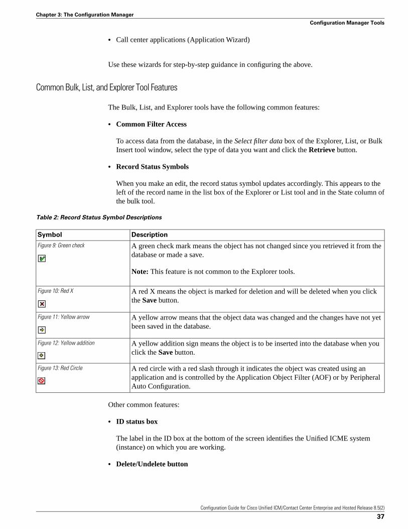
• Call center applications (Application Wizard)
Use these wizards for step-by-step guidance in configuring the above.
Common Bulk, List, and Explorer Tool Features
The Bulk, List, and Explorer tools have the following common features:
• Common Filter Access
To access data from the database, in the Select filter data box of the Explorer, List, or BulkInsert tool window, select the type of data you want and click the Retrieve button.
• Record Status Symbols
When you make an edit, the record status symbol updates accordingly. This appears to theleft of the record name in the list box of the Explorer or List tool and in the State column ofthe bulk tool.
Table 2: Record Status Symbol Descriptions
DescriptionSymbol
A green check mark means the object has not changed since you retrieved it from thedatabase or made a save.
Figure 9: Green check
Note: This feature is not common to the Explorer tools.
A red X means the object is marked for deletion and will be deleted when you clickthe Save button.
Figure 10: Red X
A yellow arrow means that the object data was changed and the changes have not yetbeen saved in the database.
Figure 11: Yellow arrow
A yellow addition sign means the object is to be inserted into the database when youclick the Save button.
Figure 12: Yellow addition
A red circle with a red slash through it indicates the object was created using anapplication and is controlled by the Application Object Filter (AOF) or by PeripheralAuto Configuration.
Figure 13: Red Circle
Other common features:
• ID status box
The label in the ID box at the bottom of the screen identifies the Unified ICME system(instance) on which you are working.
• Delete/Undelete button
Configuration Guide for Cisco Unified ICM/Contact Center Enterprise and Hosted Release 8.5(2)
37
Chapter 3: The Configuration Manager
Configuration Manager Tools
When a record is selected and you click the Delete button, that button toggles to Undeleteand a red x marks the record for deletion. As soon as you save your database changes themarked record(s) is deleted from the database.
• Save button
No changes are made to the database until you click the Save button.
Common List and Explorer Tool Features
The List and Explorer tools share the following features.
• List Box of Retrieved Records
Both the Explorer and List tools have a list box that displays retrieved records. Selecting arecord in this list displays the properties for that record in the right side of the tool window.Once displayed, you can edit a record if you have maintenance access to it.
Retrieved records
– Tree (only in Explorer tools)
In an Explorer window, the retrieved list is called a directory tree, which can be expandedor contracted to show a hierarchy of records. A legend above the tree identifies the typesof records that can be displayed in the tree.
With the mouse, you can select a record in a tree and then move it to another part of thetree, as long as its object type belongs in that tree location.
– UNASSIGNED (only in Explorer tools)
The Explorer tree can also contain UNASSIGNED records. These are stored in anUNASSIGNED directory for the selected directory tree object.
A record is named UNASSIGNED if it was not assigned (mapped) to a parent object. Forexample, a label, created in the Bulk Configuration tool, might not have been assigned toa peripheral target, or a route might not have been assigned to a service.
You can also use the Label Bulk Configuration tool to take the output of a switch andcreate 20 or 30 labels. Then, using an Explorer tool, you can attach the labels to anappropriate location.
– List (only in List tools)
In a list window, the retrieved list is called a list and has no legend above it because itsrecords have no or only one relationship to another record.
• Adding New Records
The Add button is enabled only after you use the Select filter data section of the window.
Configuration Guide for Cisco Unified ICM/Contact Center Enterprise and Hosted Release 8.5(2)
38
Chapter 3: The Configuration Manager
Configuration Manager Tools
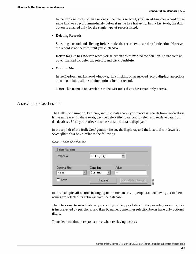
In the Explorer tools, when a record in the tree is selected, you can add another record of thesame kind or a record immediately below it in the tree hierarchy. In the List tools, the Addbutton is enabled only for the single type of records listed.
• Deleting Records
Selecting a record and clicking Delete marks the record (with a red x) for deletion. However,the record is not deleted until you click Save.
Delete toggles to Undelete when you select an object marked for deletion. To undelete anobject marked for deletion, select it and click Undelete.
• Options Menu
In the Explorer and List tool windows, right clicking on a retrieved record displays an optionsmenu containing all the editing options for that record.
Note: This menu is not available in the List tools if you have read-only access.
Accessing Database Records
The Bulk Configuration, Explorer, and List tools enable you to access records from the databasein the same way. In these tools, use the Select filter data box to select and retrieve data fromthe database. Until you retrieve database data, no data is displayed.
In the top left of the Bulk Configuration Insert, the Explorer, and the List tool windows is aSelect filter data box similar to the following.
Figure 14: Select Filter Data Box
In this example, all records belonging to the Boston_PG_1 peripheral and having JO in theirnames are selected for retrieval from the database.
The filters used to select data vary according to the type of data. In the preceding example, datais first selected by peripheral and then by name. Some filter selection boxes have only optionalfilters.
To achieve maximum response time when retrieving records
Configuration Guide for Cisco Unified ICM/Contact Center Enterprise and Hosted Release 8.5(2)
39
Chapter 3: The Configuration Manager
Configuration Manager Tools
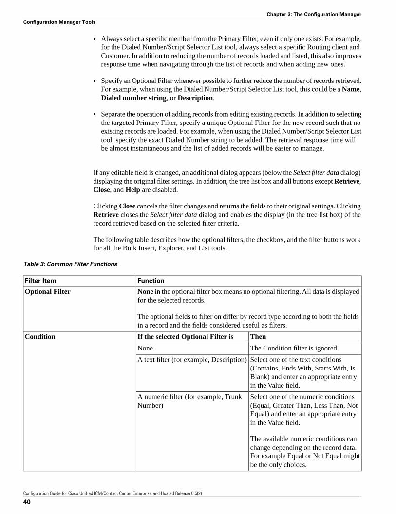
• Always select a specific member from the Primary Filter, even if only one exists. For example,for the Dialed Number/Script Selector List tool, always select a specific Routing client andCustomer. In addition to reducing the number of records loaded and listed, this also improvesresponse time when navigating through the list of records and when adding new ones.
• Specify an Optional Filter whenever possible to further reduce the number of records retrieved.For example, when using the Dialed Number/Script Selector List tool, this could be a Name,Dialed number string, or Description.
• Separate the operation of adding records from editing existing records. In addition to selectingthe targeted Primary Filter, specify a unique Optional Filter for the new record such that noexisting records are loaded. For example, when using the Dialed Number/Script Selector Listtool, specify the exact Dialed Number string to be added. The retrieval response time willbe almost instantaneous and the list of added records will be easier to manage.
If any editable field is changed, an additional dialog appears (below the Select filter data dialog)displaying the original filter settings. In addition, the tree list box and all buttons except Retrieve,Close, and Help are disabled.
Clicking Close cancels the filter changes and returns the fields to their original settings. ClickingRetrieve closes the Select filter data dialog and enables the display (in the tree list box) of therecord retrieved based on the selected filter criteria.
The following table describes how the optional filters, the checkbox, and the filter buttons workfor all the Bulk Insert, Explorer, and List tools.
Table 3: Common Filter Functions
FunctionFilter Item
None in the optional filter box means no optional filtering. All data is displayedfor the selected records.
Optional Filter
The optional fields to filter on differ by record type according to both the fieldsin a record and the fields considered useful as filters.
ThenIf the selected Optional Filter isCondition
The Condition filter is ignored.None
Select one of the text conditions(Contains, Ends With, Starts With, Is
A text filter (for example, Description)
Blank) and enter an appropriate entryin the Value field.
Select one of the numeric conditions(Equal, Greater Than, Less Than, Not
A numeric filter (for example, TrunkNumber)
Equal) and enter an appropriate entryin the Value field.
The available numeric conditions canchange depending on the record data.For example Equal or Not Equal mightbe the only choices.
Configuration Guide for Cisco Unified ICM/Contact Center Enterprise and Hosted Release 8.5(2)
40
Chapter 3: The Configuration Manager
Configuration Manager Tools
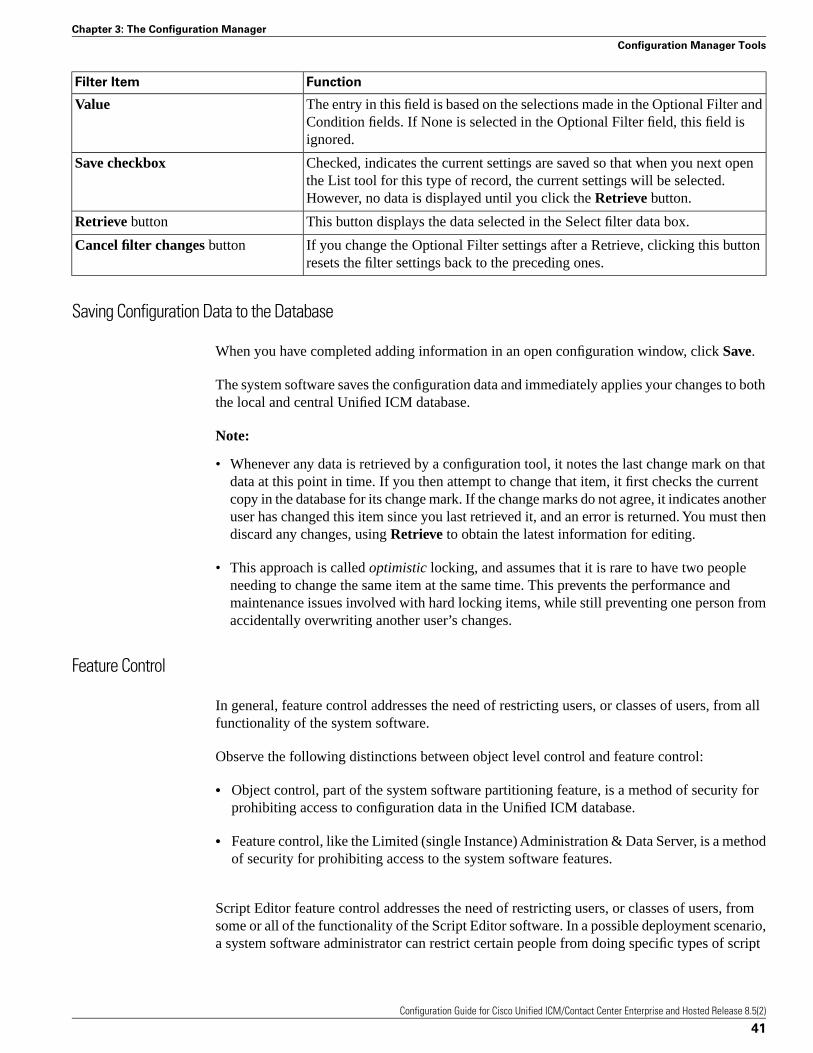
FunctionFilter Item
The entry in this field is based on the selections made in the Optional Filter andCondition fields. If None is selected in the Optional Filter field, this field isignored.
Value
Checked, indicates the current settings are saved so that when you next openthe List tool for this type of record, the current settings will be selected.However, no data is displayed until you click the Retrieve button.
Save checkbox
This button displays the data selected in the Select filter data box.Retrieve button
If you change the Optional Filter settings after a Retrieve, clicking this buttonresets the filter settings back to the preceding ones.
Cancel filter changes button
Saving Configuration Data to the Database
When you have completed adding information in an open configuration window, click Save.
The system software saves the configuration data and immediately applies your changes to boththe local and central Unified ICM database.
Note:
• Whenever any data is retrieved by a configuration tool, it notes the last change mark on thatdata at this point in time. If you then attempt to change that item, it first checks the currentcopy in the database for its change mark. If the change marks do not agree, it indicates anotheruser has changed this item since you last retrieved it, and an error is returned. You must thendiscard any changes, using Retrieve to obtain the latest information for editing.
• This approach is called optimistic locking, and assumes that it is rare to have two peopleneeding to change the same item at the same time. This prevents the performance andmaintenance issues involved with hard locking items, while still preventing one person fromaccidentally overwriting another user’s changes.
Feature Control
In general, feature control addresses the need of restricting users, or classes of users, from allfunctionality of the system software.
Observe the following distinctions between object level control and feature control:
• Object control, part of the system software partitioning feature, is a method of security forprohibiting access to configuration data in the Unified ICM database.
• Feature control, like the Limited (single Instance) Administration & Data Server, is a methodof security for prohibiting access to the system software features.
Script Editor feature control addresses the need of restricting users, or classes of users, fromsome or all of the functionality of the Script Editor software. In a possible deployment scenario,a system software administrator can restrict certain people from doing specific types of script
Configuration Guide for Cisco Unified ICM/Contact Center Enterprise and Hosted Release 8.5(2)
41
Chapter 3: The Configuration Manager
Configuration Manager Tools
editing. Similar functionality was previously available in the system software in the “Limited(single Instance) Administration & Data Servers”.
An administrator has two means to restrict access to the editing features of Script Editor andInternet Script Editor:
• Edit options
• Script node control
It is also possible for an administrator to use a combination of both feature control options.
Note:
• In previous Unified ICM Software versions (including, and before Unified ICM 4.x), anychange made to the read-only status of a user was not dynamically updated in the ScriptEditor. The Script Editor had to be closed, then reopened before the change took effect.
• In Unified ICM Release 7.0(0) and higher, any change made to a user’s read-only status(using the User List tool) is automatically updated in Script Editor.
See the Scripting and Media Routing Guide for Cisco Unified ICM/Contact Center Enterprise& Hosted for additional feature control information.
Script Node Control
Script node control allows an administrator to create feature sets that can be assigned to users.The feature set controls which script nodes are accessible to the user.
Node Control Table
The node control table (on the Configuration Manager Script Editor Feature Control dialog)has two columns, the Node column and the Available column. This table allows an administratorto create feature control sets that can be assigned to users. The feature control set controls whichscript nodes are accessible to the user.
If a script is opened that contains a disabled node, you can browse or monitor the script but youcannot put the script into edit mode. If you attempt to put this script into edit mode a messageindicating you are not authorized to enter edit mode is displayed. However, you can still QuickEdit the script, just not the node.
Node column
A node is an executable element within a script. A script consists of nodes, connections, routingtargets, and comments. Every script begins with a Start node. This column lists of all the nodesthat can be used in a script.
Configuration Guide for Cisco Unified ICM/Contact Center Enterprise and Hosted Release 8.5(2)
42
Chapter 3: The Configuration Manager
Configuration Manager Tools
Available column
Each checked node in this column appears on editing pallet of the feature-control-set user,regardless of the edit mode (Full Edit or Quick Edit Only).
There are two possible presentation effects:
• Enabled nodes are displayed on the object palette
• Disabled nodes are removed from the object palette
Configuring a Feature Control Set
Configuring a feature control set consists of:
• Creating a feature controls set (see the “How to Create a Feature Control Set (page 43)”section)
• Assigning users to a feature controls set (see the “How to Assign Users to a Feature ControlSet (page 44)” section)
• Selecting the script nodes available in a feature controls set (see the “How to Select ScriptNodes for a Feature Control Set (page 44)” section)
How to Create a Feature Control Set
The system administrator can create a feature control set using the Configuration Manager onthe Unified ICM Administration & Data Server.
Step 1 Ensure that the user or users that the feature set is to be assigned to are configured.
Step 2 Start the Configuration Manager by selecting Start > All Programs > Cisco Unified CCETools > Administration Tools > Configuration Manager. The Configuration Manager dialogopens.
Step 3 Select Tools > List Tools > Feature Control Set List.
Step 4 In the Feature Control Set section (on the left), click Add.
Step 5 Select the Attributes tab.
Step 6 Enter the name of the feature control set. The name appears in the left section when Enter orTab is pressed.
Step 7 Enter a description (optional).
Configuration Guide for Cisco Unified ICM/Contact Center Enterprise and Hosted Release 8.5(2)
43
Chapter 3: The Configuration Manager
Configuration Manager Tools
How to Assign Users to a Feature Control Set
The system administrator can assign users to a feature control set:
Step 1 Start the Configuration Manager by selecting Start > All Programs > Cisco Unified CCETools > Administration Tools > Configuration Manager. The Configuration Manager dialogopens.
Step 2 Select Tools > List Tools > User List.
Step 3 Select the user to whom feature control set is to be assigned.
Note: If no users appear, add the user(s) using the User List tool.
Step 4 On the Attribute tab, select the feature set for the selected user.
Step 5 Click Save when you are finished assigning feature sets.
How to Select Script Nodes for a Feature Control Set
To select script nodes:
Step 1 Select the name of the feature control set to be assigned.
Step 2 Select the Attributes tab.
Step 3 Select Advanced (under Script Editor).
Step 4 In the Script Editor Feature Control dialog, select the nodes for this feature control set and anedit option (Full Edit or Quick Edit).
Step 5 Click OK.
Step 6 Click Save.
Validating Configuration Data
After making changes or additions to your configuration, you must always check that it isinternally consistent and complete.
Note: It is especially important to perform integrity checks if you have imported data fromanother source.
Configuration Guide for Cisco Unified ICM/Contact Center Enterprise and Hosted Release 8.5(2)
44
Chapter 3: The Configuration Manager
Configuration Manager Tools
How to Check the Integrity of Your Configuration Data
To check the integrity of your configuration data, perform the following:
Step 1 In the Configuration Manager menu, select Miscellaneous Tools > Integrity Check. TheIntegrity Check dialog appears.
Step 2 Choose the type of check option that you want to perform or click Select All to choose all thecheck options. (For specific information about each of these options and the tables and fieldsthey check, see the Configuration Manager online help.)
Step 3 Click Perform Check. The Configuration Manager performs the check and one of the followinghappens:
a. If the check discovers a problem, the Configuration Manager displays messages in theIntegrity Problems text box. Double-click on a message to receive specific informationabout the records in the data table at the bottom of the window.
b. If the check is completed without finding any invalid data, the Configuration Managerdisplays a message saying the integrity check completed successfully.
Step 4 When all checks are complete, click Close. The Integrity Check dialog closes.
Many database records need references to related records. For example, each peripheral targetought to reference a route and each trunk group ought to reference a network trunk group.
How to Check Record References
To check record references, perform the following:
Step 1 In the Configuration Manager menu, select Miscellaneous Tools > Unreferenced Objects.The Unreferenced Object dialog appears listing the database tables containing objects that aremissing references.
Step 2 To see the specific rows that are missing references in a table, double-click on the table name.Double-clicking on a table name entry displays that table showing the records that are missingreferences.
Deleting Configuration Records
At some point, you might want to remove configuration records from your database; for example,if data is entered in error or changes occur in your business.
Configuration Guide for Cisco Unified ICM/Contact Center Enterprise and Hosted Release 8.5(2)
45
Chapter 3: The Configuration Manager
Configuration Manager Tools
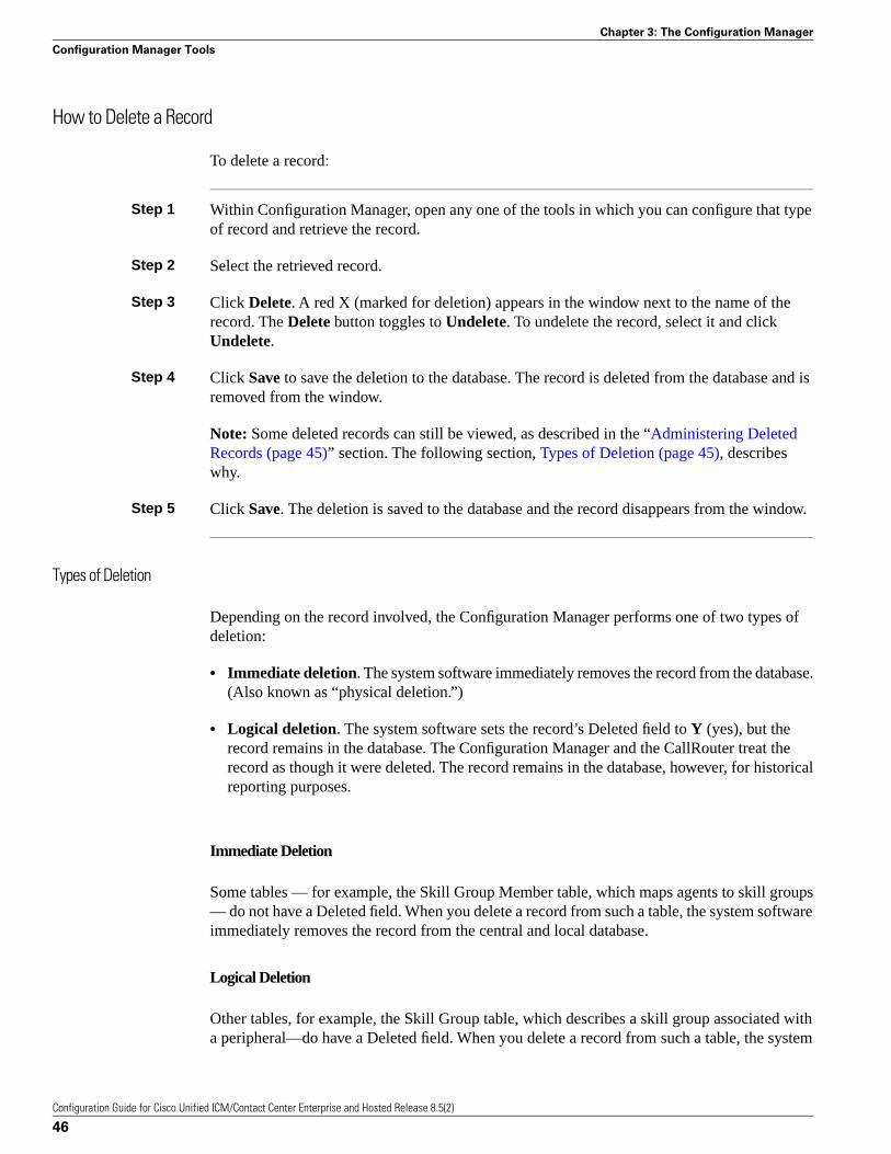
How to Delete a Record
To delete a record:
Step 1 Within Configuration Manager, open any one of the tools in which you can configure that typeof record and retrieve the record.
Step 2 Select the retrieved record.
Step 3 Click Delete. A red X (marked for deletion) appears in the window next to the name of therecord. The Delete button toggles to Undelete. To undelete the record, select it and clickUndelete.
Step 4 Click Save to save the deletion to the database. The record is deleted from the database and isremoved from the window.
Note: Some deleted records can still be viewed, as described in the “Administering DeletedRecords (page 45)” section. The following section, Types of Deletion (page 45), describeswhy.
Step 5 Click Save. The deletion is saved to the database and the record disappears from the window.
Types of Deletion
Depending on the record involved, the Configuration Manager performs one of two types ofdeletion:
• Immediate deletion. The system software immediately removes the record from the database.(Also known as “physical deletion.”)
• Logical deletion. The system software sets the record’s Deleted field to Y (yes), but therecord remains in the database. The Configuration Manager and the CallRouter treat therecord as though it were deleted. The record remains in the database, however, for historicalreporting purposes.
Immediate Deletion
Some tables — for example, the Skill Group Member table, which maps agents to skill groups— do not have a Deleted field. When you delete a record from such a table, the system softwareimmediately removes the record from the central and local database.
Logical Deletion
Other tables, for example, the Skill Group table, which describes a skill group associated witha peripheral—do have a Deleted field. When you delete a record from such a table, the system
Configuration Guide for Cisco Unified ICM/Contact Center Enterprise and Hosted Release 8.5(2)
46
Chapter 3: The Configuration Manager
Configuration Manager Tools
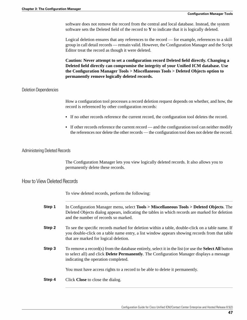
software does not remove the record from the central and local database. Instead, the systemsoftware sets the Deleted field of the record to Y to indicate that it is logically deleted.
Logical deletion ensures that any references to the record — for example, references to a skillgroup in call detail records — remain valid. However, the Configuration Manager and the ScriptEditor treat the record as though it were deleted.
Caution: Never attempt to set a configuration record Deleted field directly. Changing aDeleted field directly can compromise the integrity of your Unified ICM database. Usethe Configuration Manager Tools > Miscellaneous Tools > Deleted Objects option topermanently remove logically deleted records.
Deletion Dependencies
How a configuration tool processes a record deletion request depends on whether, and how, therecord is referenced by other configuration records:
• If no other records reference the current record, the configuration tool deletes the record.
• If other records reference the current record — and the configuration tool can neither modifythe references nor delete the other records — the configuration tool does not delete the record.
Administering Deleted Records
The Configuration Manager lets you view logically deleted records. It also allows you topermanently delete these records.
How to View Deleted Records
To view deleted records, perform the following:
Step 1 In Configuration Manager menu, select Tools > Miscellaneous Tools > Deleted Objects. TheDeleted Objects dialog appears, indicating the tables in which records are marked for deletionand the number of records so marked.
Step 2 To see the specific records marked for deletion within a table, double-click on a table name. Ifyou double-click on a table name entry, a list window appears showing records from that tablethat are marked for logical deletion.
Step 3 To remove a record(s) from the database entirely, select it in the list (or use the Select All buttonto select all) and click Delete Permanently. The Configuration Manager displays a messageindicating the operation completed.
You must have access rights to a record to be able to delete it permanently.
Step 4 Click Close to close the dialog.
Configuration Guide for Cisco Unified ICM/Contact Center Enterprise and Hosted Release 8.5(2)
47
Chapter 3: The Configuration Manager
Configuration Manager Tools

Configuring Bucket Intervals
You can configure call type intervals in relation to your service levels. For example, if yourservice level threshold is 15 seconds and you want to see when callers are abandoning withinthat service level, you can set intervals of 5 seconds, 10 seconds, and 15 seconds.
How to Configure Bucket Intervals
Note: The “Configuring Call Types on the Child Central Controller (page 48)” section containsan example of how to configure call types on a child deployment, which is documented in theCisco Contact Center Gateway Deployment Guide for Cisco Unified ICME/CCE/CCX.
Reports can display information from up to ten intervals. You can configure up to nine intervals,and the tenth interval shows all the remaining data. To configure bucket intervals, perform thefollowing:
Step 1 Open the Configuration Manager tool and expand the Tools menu.
Step 2 Expand the List Tools menu and double-click Bucket Intervals List.
Step 3 Click Retrieve to display the default values.
Step 4 Click Add to add a new list of interval values.
Step 5 In the Name filed of the Attributes tab, assign the list a name.
Step 6 Assign your new values to the Upper bound 1 - 9 fields.
Step 7 Click Close to close the Bucket Interval List tool.
Step 8 Double-click the Call Type List tool.
Step 9 Click Add.
Step 10 In the Name field of the Attributes tab, assign the new list a name.
Step 11 Select the Customer from the pull-down menu.
Step 12 Check the Override System Information Default box for the Bucket intervals section.
Step 13 Using the pull-down menu, select the Bucket intervals list you previously created.
Configuring Call Types on the Child Central Controller
Access the Configuration Manager on the Child Administration & Data Server to configure calltypes.
Configuration Guide for Cisco Unified ICM/Contact Center Enterprise and Hosted Release 8.5(2)
48
Chapter 3: The Configuration Manager
Configuration Manager Tools
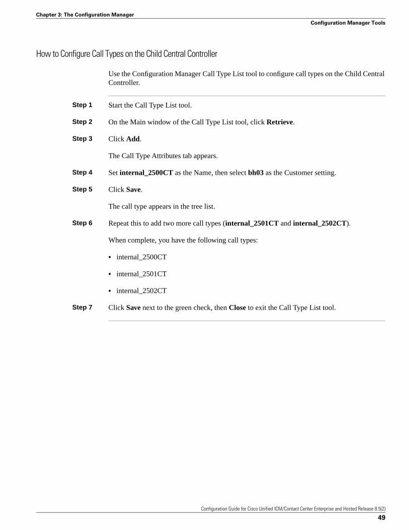
How to Configure Call Types on the Child Central Controller
Use the Configuration Manager Call Type List tool to configure call types on the Child CentralController.
Step 1 Start the Call Type List tool.
Step 2 On the Main window of the Call Type List tool, click Retrieve.
Step 3 Click Add.
The Call Type Attributes tab appears.
Step 4 Set internal_2500CT as the Name, then select bh03 as the Customer setting.
Step 5 Click Save.
The call type appears in the tree list.
Step 6 Repeat this to add two more call types (internal_2501CT and internal_2502CT).
When complete, you have the following call types:
• internal_2500CT
• internal_2501CT
• internal_2502CT
Step 7 Click Save next to the green check, then Close to exit the Call Type List tool.
Configuration Guide for Cisco Unified ICM/Contact Center Enterprise and Hosted Release 8.5(2)
49
Chapter 3: The Configuration Manager
Configuration Manager Tools

Configuration Guide for Cisco Unified ICM/Contact Center Enterprise and Hosted Release 8.5(2)
50
Chapter 3: The Configuration Manager
Configuration Manager Tools
Configuring Multiple Records at a TimeThis chapter shows you how to use the Configuration Manager Bulk Configuration tool to insertand update multiple configuration records in a single transaction from a single screen.
In some cases, you might need to work with multiple records of configuration datasimultaneously.
For example, you might want to:
• Import records from a text file
• Modify a specific field in multiple records
• Insert a set of records
The Bulk Configuration tool lets you perform these operations on several Unified ICM datatables simultaneously. This tool supplements the Configuration Manager Explorer and Listtools, which allow you to insert and update single records.
Note: See the Bulk Configuration tool online help for detailed information.
This chapter contains the following topics:
• How to Access the Bulk Configuration Tools, page 51• Data You Can Bulk Configure, page 52• Insert and Edit Windows, page 52• Bulk Configuration Features , page 53
How to Access the Bulk Configuration Tools
To access the Bulk Configuration tools, follow these steps:
Configuration Guide for Cisco Unified ICM/Contact Center Enterprise and Hosted Release 8.5(2)
51
Chapter 4
Step 1 Double-click Configuration Manager in the Administration Data Server group or theAdministration Client group.
Step 2 In the Menu selection box, select Tools > Bulk Configuration.
Step 3 Then from the submenu selection list, select Insert if you need to insert data or Edit if you needto edit.
Step 4 Finally, in the next menu selection list, select the type of table with which you need to work.
Data You Can Bulk Configure
From the Bulk Configuration menu, you can choose to create or update records in the databasetables.
Start by selecting the Bulk Configuration Insert or Edit menu. Then select the database tableyou want to modify.
If you have any questions, see the online help. The help contains table record and field definitionsand procedures for all that you can do with the Bulk Configuration tool. The following sectionsbriefly describe the tool and how to use it.
Insert and Edit Windows
Depending on whether you select Bulk Configuration Insert or Edit, the Bulk ConfigurationInsert or Edit window for the selected database table opens.
These two windows have the following features:
• Same Options
Both windows have the same options except for Insert (Insert window) and Retrieve (Editwindow).
Reason for Two Windows
The reason for having both an insert and an edit window is to prevent confusion when editingrecords. Because the database is relational, some configuration objects can only be editedwhen inserted into the database. For example, when you insert the record of a label, you canedit all of its fields. However, once you define its routing client (and save it in the database),the only way you can redefine the routing client is by deleting the label and creating a newone.
• Saving Changes
Configuration Guide for Cisco Unified ICM/Contact Center Enterprise and Hosted Release 8.5(2)
52
Chapter 4: Configuring Multiple Records at a Time
Data You Can Bulk Configure
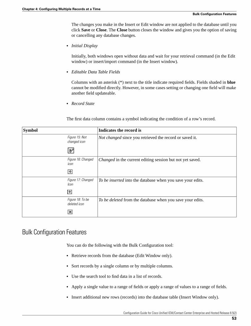
The changes you make in the Insert or Edit window are not applied to the database until youclick Save or Close. The Close button closes the window and gives you the option of savingor cancelling any database changes.
• Initial Display
Initially, both windows open without data and wait for your retrieval command (in the Editwindow) or insert/import command (in the Insert window).
• Editable Data Table Fields
Columns with an asterisk (*) next to the title indicate required fields. Fields shaded in bluecannot be modified directly. However, in some cases setting or changing one field will makeanother field updateable.
• Record State
The first data column contains a symbol indicating the condition of a row’s record.
Indicates the record isSymbol
Not changed since you retrieved the record or saved it.Figure 15: Notchanged icon
Changed in the current editing session but not yet saved.Figure 16: Changedicon
To be inserted into the database when you save your edits.Figure 17: ChangedIcon
To be deleted from the database when you save your edits.Figure 18: To bedeleted icon
Bulk Configuration Features
You can do the following with the Bulk Configuration tool:
• Retrieve records from the database (Edit Window only).
• Sort records by a single column or by multiple columns.
• Use the search tool to find data in a list of records.
• Apply a single value to a range of fields or apply a range of values to a range of fields.
• Insert additional new rows (records) into the database table (Insert Window only).
Configuration Guide for Cisco Unified ICM/Contact Center Enterprise and Hosted Release 8.5(2)
53
Chapter 4: Configuring Multiple Records at a Time
Bulk Configuration Features
• Import multiple record data (either whole records or record fields).
• Export multiple record data (either whole records or record fields).
• Set or change security settings to multiple records at a time.
• Delete records. After deletions are saved to the database (or after you close your editingsession), you can no longer undelete deleted records.
• Undelete records that are marked for deletion in the current editing session.
The following sections describe how to use the Bulk Configuration tool.
Retrieving and Editing Records
Use the Select filter data box in the Edit window to retrieve records from the database.
How to Retrieve and Edit Existing Records
To retrieve and edit existing records, follow these steps:
Step 1 Within the Bulk Configuration > Edit menu, select the name of the database table you wantto modify. The appropriate Edit window appears. (Initially, no records are shown.)
Step 2 Do one of the following:
a. To retrieve a range of records, specify values in the Select filter data fields. For example,you could enter values that would retrieve only dialed numbers associated with a specificcustomer, with a specific routing client, or both.
b. To retrieve all records, leave the Customer and Routing Client fields set to All.
Step 3 Click Retrieve. The appropriate rows are displayed in the Edit window as in the followingexample.
Configuration Guide for Cisco Unified ICM/Contact Center Enterprise and Hosted Release 8.5(2)
54
Chapter 4: Configuring Multiple Records at a Time
Bulk Configuration Features
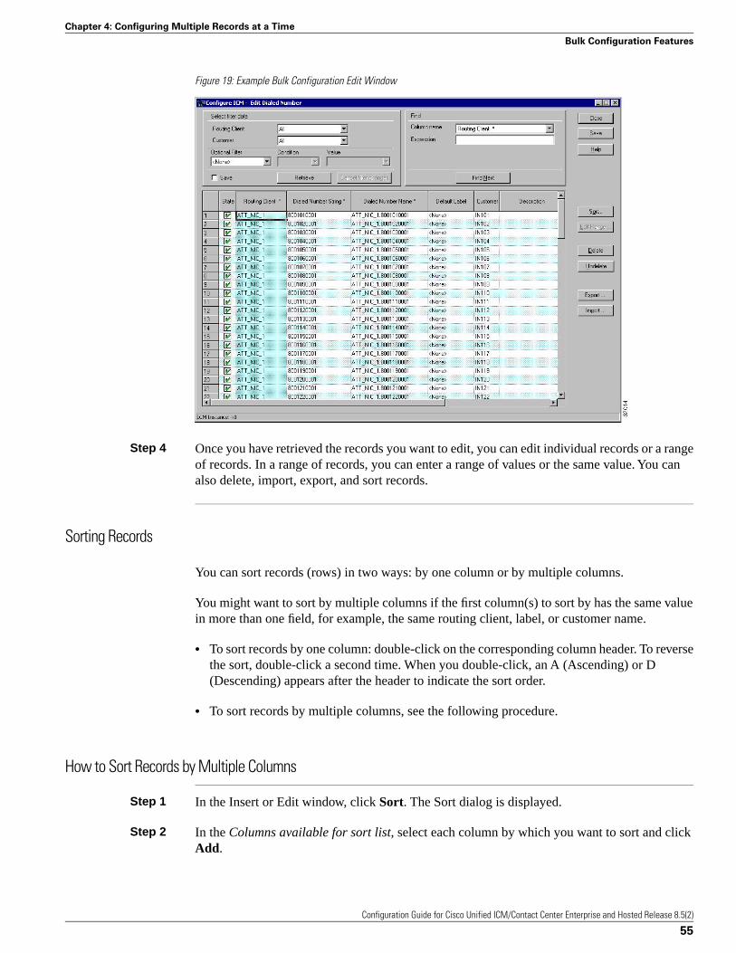
Figure 19: Example Bulk Configuration Edit Window
Step 4 Once you have retrieved the records you want to edit, you can edit individual records or a rangeof records. In a range of records, you can enter a range of values or the same value. You canalso delete, import, export, and sort records.
Sorting Records
You can sort records (rows) in two ways: by one column or by multiple columns.
You might want to sort by multiple columns if the first column(s) to sort by has the same valuein more than one field, for example, the same routing client, label, or customer name.
• To sort records by one column: double-click on the corresponding column header. To reversethe sort, double-click a second time. When you double-click, an A (Ascending) or D(Descending) appears after the header to indicate the sort order.
• To sort records by multiple columns, see the following procedure.
How to Sort Records by Multiple Columns
Step 1 In the Insert or Edit window, click Sort. The Sort dialog is displayed.
Step 2 In the Columns available for sort list, select each column by which you want to sort and clickAdd.
Configuration Guide for Cisco Unified ICM/Contact Center Enterprise and Hosted Release 8.5(2)
55
Chapter 4: Configuring Multiple Records at a Time
Bulk Configuration Features
The primary sorting column will be the first column listed in the Columns selected for sort list.To change the column sort order, select a column and click the up or down arrow.
The data within each column is sorted in Ascending order unless you deselect the checkboxbeside the column.
Step 3 Click OK.
Finding Data in a List of Records
After you have retrieved a set of records, you can use the Find area of the Edit window (ColumnName and Expression fields) to search for specific records within the set.
How to Find Data
To find data in a list of records follow these steps:
Step 1 In Find box of the Edit or Insert window, select the database column in which you want tosearch for data.
Note: You can also select a column by clicking in that column.
Step 2 In the Find box Expression field, enter the value for which you want to search. You can entera full value or a sub-string.
Step 3 Click Find Next to locate the first record that matches the search criteria. The first row thatcontains the specified expression in the selected column is highlighted.
Selecting Data
You can select whole records for importing, exporting, setting security, deleting, or undeleting.Or, you can select the same field in multiple records for simultaneous editing.
How to Select Records
Clicking in the left-most numbered field in a row both selects that row and highlights it. Clickingin any field in a row also selects the row but does not highlight it.
How to Select One Field in Multiple Records
You can select one edit-control field (when there is no section box in the field) in multiplerecords in any one of the following three ways:
• Click the field where you want to start and, keeping the left mouse button held down, movethe cursor to the last field.
Configuration Guide for Cisco Unified ICM/Contact Center Enterprise and Hosted Release 8.5(2)
56
Chapter 4: Configuring Multiple Records at a Time
Bulk Configuration Features

• Click the field where you want to start. While holding down the Shift key, click the last field.
• Click the field where you want to start. While holding down the Shift key, make your selectionby clicking the down arrow.
• Press Ctrl, then left-click on each field you wish to select. This allows you to select a randomgroup of fields.
For selecting one value in multiple selection box fields, see the following section, “Editinga Range of Data (page 57).”
Editing a Range of Data
You can edit a range of data in a table column in several ways:
• Apply a single value to a range of (edit-control) fields
• Apply a single value to a range of selection-box fields
• Apply a range of values to a range of fields
How to Apply a Single Value to a Range of Edit-Control Fields
An edit-control field is one you can edit that does not contain a selection box.
Step 1 Make your selection: click the field where you want the range to start and, keeping the leftmouse button held down, move the cursor to the last field in the range.
Step 2 Type the new entry that you want to appear in all the fields.
Step 3 Click Enter or Tab. This applies the change to all the records in the range and moves the focusto the next data field.
How to Apply a Single Value to a Range of Selection-Box Fields
Step 1 Select the first field where you want the range to start.
Step 2 Hold down the Shift key and keep it down for steps 3, 4, and 5.
Step 3 Click the selection-box down arrow but keep the left mouse button held down and select thefields you want in the range.
Step 4 Click the last field in the selection to display the selection list. You can also open the selectionbox by pressing Alt + an arrow key.
Step 5 Click your selection.
Configuration Guide for Cisco Unified ICM/Contact Center Enterprise and Hosted Release 8.5(2)
57
Chapter 4: Configuring Multiple Records at a Time
Bulk Configuration Features
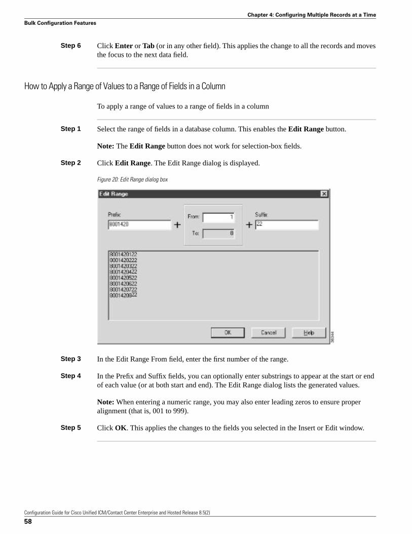
Step 6 Click Enter or Tab (or in any other field). This applies the change to all the records and movesthe focus to the next data field.
How to Apply a Range of Values to a Range of Fields in a Column
To apply a range of values to a range of fields in a column
Step 1 Select the range of fields in a database column. This enables the Edit Range button.
Note: The Edit Range button does not work for selection-box fields.
Step 2 Click Edit Range. The Edit Range dialog is displayed.
Figure 20: Edit Range dialog box
Step 3 In the Edit Range From field, enter the first number of the range.
Step 4 In the Prefix and Suffix fields, you can optionally enter substrings to appear at the start or endof each value (or at both start and end). The Edit Range dialog lists the generated values.
Note: When entering a numeric range, you may also enter leading zeros to ensure properalignment (that is, 001 to 999).
Step 5 Click OK. This applies the changes to the fields you selected in the Insert or Edit window.
Configuration Guide for Cisco Unified ICM/Contact Center Enterprise and Hosted Release 8.5(2)
58
Chapter 4: Configuring Multiple Records at a Time
Bulk Configuration Features
Inserting New Records
You can insert new records by inserting multiple blank rows (records) and filling in the data(see the “How to Insert New Records (page 59)” section, or by importing the data (see the“How to Import Data (page 60)” section).
You can also edit the data you insert when you insert it.
How to Insert New Records
Step 1 In the Bulk Configuration > Insert menu, select the name of the data table to which you wantto add records. The appropriate Insert window opens, automatically displaying one new row.
Step 2 To create additional rows, enter the number of additional rows in the Quantity field and clickInsert. The additional rows are added in the Insert window.
Step 3 Enter the data in the rows:
a. If you want to edit individual fields in the new rows, type the information you want ineach of the fields and go to Step 8.
b. If you want to edit a column in multiple rows so that a range of values is entered, go toStep 4.
c. For other ways of entering data into multiple rows, see the “Editing a Range of Data (page57)” section.
Step 4 Select the rows in the column you want to modify.
Step 5 Click Edit Range. The Edit Range dialog appears.
Step 6 Enter a prefix (optional), the start value for the range, and a suffix (optional). The generatedvalues are listed in the dialog.
Step 7 Click OK to close the Edit Range dialog and apply the values to the column you selected.
Step 8 When you have finished setting fields in the new rows, press Enter to apply your changes tothe Unified ICM database.
You can leave empty rows, the system ignores them.
Note: No changes are made to the database until you press Enter.
Configuration Guide for Cisco Unified ICM/Contact Center Enterprise and Hosted Release 8.5(2)
59
Chapter 4: Configuring Multiple Records at a Time
Bulk Configuration Features
Importing Data
You can import data from a specified text file into the opened database table. Whole records oronly columns of data can be imported, if the data matches (see Step 3 of the following procedure).If any error occurs during the import process, the process is cancelled.
How to Import Data
Step 1 In the Insert or Edit window, click Import.
Step 2 In the Import dialog, click File.
Step 3 In the File Open dialog, select the file containing the data you want to import and click Open.For a description of the required import-file format, see the “Import/Export Data File Format(page 61)” section following this procedure.
The Import File Data area displays the first few lines of the opened file.
• When importing data in the Edit mode, the following rules apply:
– The Bulk Configuration tool reads only those records whose primary key values matchthose of records in the Edit window.
If there is a record that does not match the primary key value, the record is considered tobe an error and a message box with the primary key value pops up to ask you to correctthe problem.
– If any field in the import record is null, the corresponding field value in the grid windowbecome blank for an edit cell or uses the default value for a drop-down list cell.
– If any field is missing in the import file, the corresponding field in the Edit window remainunchanged.
– If there is a larger number of records in the file to be imported than the number of rowsin the grid, it is considered as an error and a message box pops up asking you to correctit.
– If there is a duplicated primary key in the file to be imported, it is considered as an error.A message box with the duplicated primary key value pops up asking you to correct it.
– After importing, all records imported (including records marked for deletion in the grid)are marked as “Changed” regardless whether the value is changed or not.
– After a importing, the records are displayed in index order (ordered by logical keys). Ifyou did not sort before importing, the order appears the same after the import.
• When importing data in the Insert mode, the following rules apply:
Configuration Guide for Cisco Unified ICM/Contact Center Enterprise and Hosted Release 8.5(2)
60
Chapter 4: Configuring Multiple Records at a Time
Bulk Configuration Features
– Only a single import is supported and any existing rows are removed from the grid. Whenyou click Import, a message box pops up if there is any record in the grid. You will seethe following message:
“All the existing data will be replaced by the data to be imported. If you want to retain thecurrent data on the grid please click the Cancel button then save or export the existingdata. Click the OK button to proceed with the importing.”
– After importing, all rows are marked as “New” and the ordering is the same as that in thefile imported from.
– In the Import Insert mode, the tool reads only those records whose primary key values arenot presented. If the primary key field is selected for file to be imported, it is consideredan error and a message box with the primary key field name pops up asking you to correctthe problem.
– If any field in the import record is null, the corresponding field value in the grid windowbecomes blank for an edit cell or uses the default value for a drop-down list cell.
Note: If headers are included in the imported file, the Add and Remove buttons are notenabled and you can only import the record(s) as a whole. In that case, go to Step 6.
Step 4 If the imported data does not contain headers, in the Available Fields list box, select the namesof the fields to import that match the data and click Add.
Step 5 To change the order of the columns, select a column and move it within the list by clicking Upor Down.
Step 6 Click OK. The data is imported into the data table.
Import/Export Data File Format
The import and export files used by the Bulk Configuration tool can optionally include a headerthat identifies the table and columns in the file. The header is followed by one line for each rowof data.
The following rules apply to the file headers:
• A line beginning with a number sign (#) is a comment and is ignored.
• Blank lines are also ignored.
• The header content is indicated by a line beginning with two underline characters and theword TABLE or COLUMNS. The following line contains the name of the table or the nameof the columns. For example:__TABLE
Call_Type __
COLUMNS
Configuration Guide for Cisco Unified ICM/Contact Center Enterprise and Hosted Release 8.5(2)
61
Chapter 4: Configuring Multiple Records at a Time
Bulk Configuration Features
CallTypeID EnterpriseName Description Deleted CustomerDefinitionID
• All column names must be on a single line and are separated by Tab characters.
The following rules apply to the data in the files:
– One row of table data per line.
– Column values must be in the same order in all rows. If columns are specified in the header,the columns in the data rows must be in the same order.
– Column values are separated by a single Tab character.
– Fields intentionally left blank must be represented by two adjacent Tab characters or aTab character at the end of a line. On import, the default value is used for such a value.
– String values may include spaces.
– An error occurs on import if a line contains too few or too many values.
Note: A simple way to create the import file with a valid format is to use Excel and save itas Text (Tab delimited) (*.TXT).
Exporting Data
The export function saves the selected records or field(s) to a tab-delimited text file that youcan import into the Unified ICM database or into a database tool such as Microsoft Excel. Ifany error occurs during the export process, the process is cancelled.
How to Export Data
To export data, follow these steps:
Step 1 Select the rows with fields you want to export.
Note:
• If you intend to import this data into the Edit window, you must export a primary key fieldalong with any other fields. The primary key field has the same column name as the databasetable name.
• All rows selected (including records marked for deletion) are exported.
Step 2 Click Export.
Step 3 Select the Header option if you want to include a header containing the table name and columnnames in the output file. Including the header clarifies the content of the file.
Step 4 In the Export dialog, select the column(s) you want to export and click Add or AddAll.
Configuration Guide for Cisco Unified ICM/Contact Center Enterprise and Hosted Release 8.5(2)
62
Chapter 4: Configuring Multiple Records at a Time
Bulk Configuration Features
Step 5 To change the order of the columns to export, select one of them and move it within the list byclicking Up or Down.
Step 6 Click File and specify the file name and directory to which to save the data.
Step 7 Click OK.
Applying Security Settings to Multiple Records
For the Security button (in the Explorer and Bulk tools) or tab (in the List tools) to be visibleand enabled:
• The Unified ICM Partition installation setup option must be installed on your Unified ICMEsystem.
Note: As of Unified ICME Release 8.0(1), Partitioning is no longer supported except onsystems that already have Partitioning installed.
• You must have maintenance access to the selected database record(s) and to the system class.
How to View or Apply Security Settings
To view or apply security settings:
Step 1 Follow the steps for viewing the item whose security setting you want to see or apply. (See theonline help if you have questions.)
The configuration information for the selected item is displayed.
Step 2 Select the item or items with security settings that you want to view or edit.
Note: You can apply security setting to more than one record at a time only in the BulkConfiguration tool. In the bulk configuration tool window, if there are security settings on theselected records and they are mixed (different records having different settings), no securitydata is displayed. If you want to apply one setting to records with mixed settings, select Overrideexisting settings.
Step 3 Click Security. The Security dialog is displayed.
Step 4 View or make the security settings.
To view or make the security settings:
• To remove access to the records: In the User Access display area of the Security dialog, selectthe user or group to remove and click Remove.
Configuration Guide for Cisco Unified ICM/Contact Center Enterprise and Hosted Release 8.5(2)
63
Chapter 4: Configuring Multiple Records at a Time
Bulk Configuration Features
• To edit access to the records: In the User Access display area, select the user or group to editand click Edit or double-click on the item you want to edit. Then in the Edit Permissionsdialog, select the access type and click OK.
• To add access to the selected records:
– Click Add. The Add Users and Groups dialog is displayed.
– Select User or Group
– Select the user or group name(s) for which you want access rights.
– Select the Access type from the selection list and click OK:
Access Type
– Read access means a specific user or group can view or reference the object, but cannotmodify it.
– Reference access means a specific user or group can reference the object in a script. Thisincludes read access, but not write access.
– Maintenance access means a specific user or group can update or delete the object as wellas view and use it.
Step 5 When done, in the Security dialog, click OK.
Deleting and Undeleting Records
You can delete one or more records at a time and you can undelete records marked for deletion.
How to Delete Records
To delete records, follow these steps:
Step 1 Select the row(s) to be deleted.
Note: Selecting any field in a row (or any range of fields in a column) selects the rows of whichthey are a part.
Step 2 Click Delete. The selected rows are marked for deletion.
Step 3 Click Save. The rows marked for deletion are deleted from the database.
Note: You can no longer undelete records marked for deletion once you have saved your changesto the database.
Configuration Guide for Cisco Unified ICM/Contact Center Enterprise and Hosted Release 8.5(2)
64
Chapter 4: Configuring Multiple Records at a Time
Bulk Configuration Features

How to Undelete Records
Step 1 Select the rows marked for deletion.
Step 2 Click Undelete. The deletion mark is removed from the records.
Step 3 Click Save. The change is saved to the database.
Configuration Guide for Cisco Unified ICM/Contact Center Enterprise and Hosted Release 8.5(2)
65
Chapter 4: Configuring Multiple Records at a Time
Bulk Configuration Features

Configuration Guide for Cisco Unified ICM/Contact Center Enterprise and Hosted Release 8.5(2)
66
Chapter 4: Configuring Multiple Records at a Time
Bulk Configuration Features
Configuring Routing ClientsThis chapter describes how to set up routing clients and their directly related elements.
It includes:
• An introduction to the Routing Client subsystem
• Instructions on how to view, delete, modify, and define:
– Network Interface Controllers (NICs)
– Routing clients
– Dialed numbers
This chapter contains the following topics:
• The Routing Client Subsystem, page 67• Configuring a Network Interface Controller (NIC), page 70• Configuring Dialed Number/Script Selectors, page 76
The Routing Client Subsystem
A routing client is an entity that sends route requests to the system software.
A routing client can be:
• A public network interexchange carrier (IXC), such as AT&T, BT, MCI, Nortel, or Sprint
• A private network peripheral, such as an Aspect or Lucent ACD
Configuration Guide for Cisco Unified ICM/Contact Center Enterprise and Hosted Release 8.5(2)
67
Chapter 5
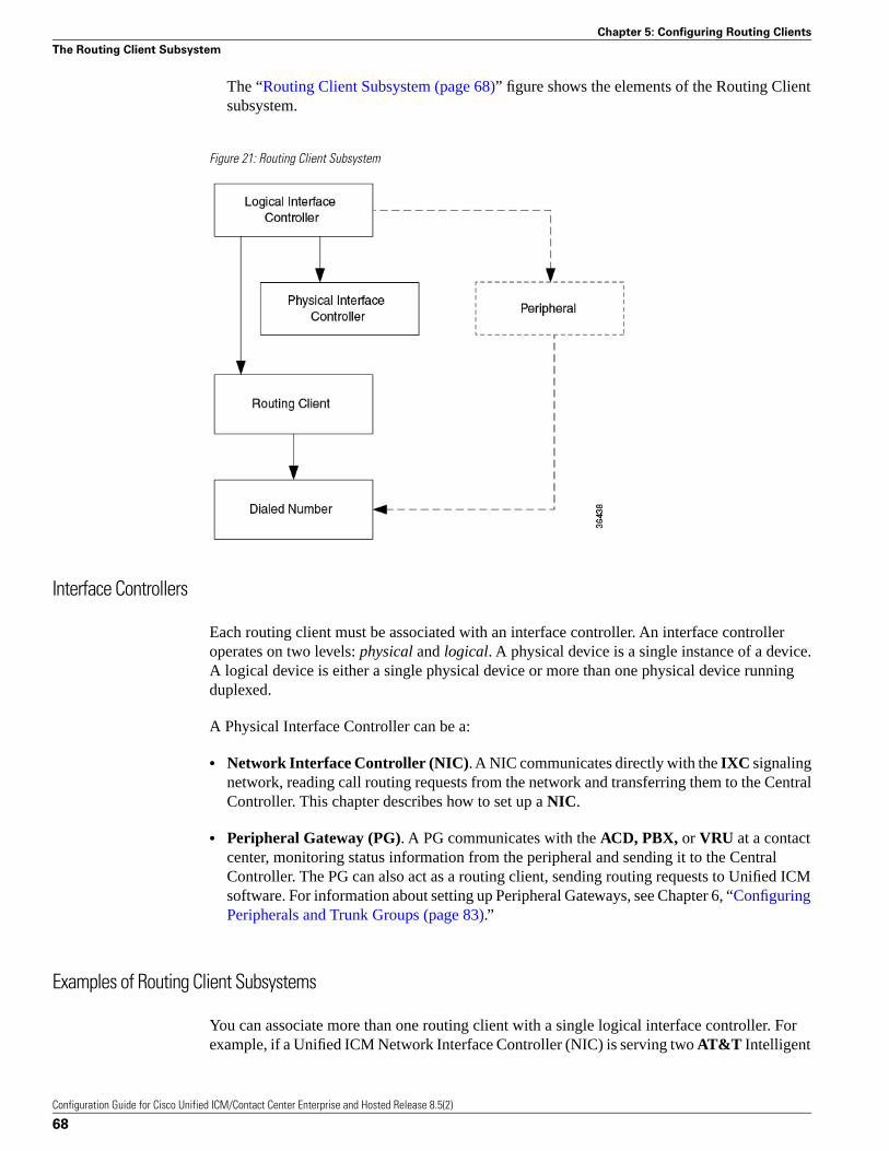
The “Routing Client Subsystem (page 68)” figure shows the elements of the Routing Clientsubsystem.
Figure 21: Routing Client Subsystem
Interface Controllers
Each routing client must be associated with an interface controller. An interface controlleroperates on two levels: physical and logical. A physical device is a single instance of a device.A logical device is either a single physical device or more than one physical device runningduplexed.
A Physical Interface Controller can be a:
• Network Interface Controller (NIC). A NIC communicates directly with the IXC signalingnetwork, reading call routing requests from the network and transferring them to the CentralController. This chapter describes how to set up a NIC.
• Peripheral Gateway (PG). A PG communicates with the ACD, PBX, or VRU at a contactcenter, monitoring status information from the peripheral and sending it to the CentralController. The PG can also act as a routing client, sending routing requests to Unified ICMsoftware. For information about setting up Peripheral Gateways, see Chapter 6, “ConfiguringPeripherals and Trunk Groups (page 83).”
Examples of Routing Client Subsystems
You can associate more than one routing client with a single logical interface controller. Forexample, if a Unified ICM Network Interface Controller (NIC) is serving two AT&T Intelligent
Configuration Guide for Cisco Unified ICM/Contact Center Enterprise and Hosted Release 8.5(2)
68
Chapter 5: Configuring Routing Clients
The Routing Client Subsystem
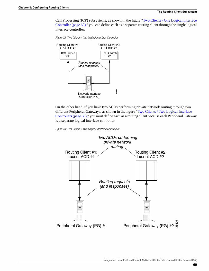
Call Processing (ICP) subsystems, as shown in the figure “Two Clients / One Logical InterfaceController (page 69),” you can define each as a separate routing client through the single logicalinterface controller.
Figure 22: Two Clients / One Logical Interface Controller
On the other hand, if you have two ACDs performing private network routing through twodifferent Peripheral Gateways, as shown in the figure “Two Clients / Two Logical InterfaceControllers (page 69),” you must define each as a routing client because each Peripheral Gatewayis a separate logical interface controller.
Figure 23: Two Clients / Two Logical Interface Controllers
Configuration Guide for Cisco Unified ICM/Contact Center Enterprise and Hosted Release 8.5(2)
69
Chapter 5: Configuring Routing Clients
The Routing Client Subsystem
Configuring a Network Interface Controller (NIC)
Use the NIC Explorer to view, define, modify, or delete Network Interface Controller informationand its associated routing client information.
The NIC Explorer generates records that set up a logical interface controller, one or morephysical interface controllers, and one or more routing clients.
How to View a NIC and Its Routing Client(s)
To view a NIC and its routing client(s), follow these steps:
Step 1 From the Configuration Manager menu, select Tools > Explorer Tools > NIC Explorer.
The NIC Explorer window appears.
Step 2 In the Select filter data box, select the filters you want.
Step 3 Click Retrieve. The name(s) of the retrieved NIC(s) are listed in the tree list box.
Step 4 In the tree list box, select the NIC whose records you want to view. The configuration informationfor the selected NIC is displayed in the fields on the right. For field descriptions, see the “NICExplorer Tab Descriptions (page 70)” section.
Step 5 To view a routing client record, in the tree list box, expand the tree branch for the selected NICand select the routing client icon (for the NIC).
The routing client configuration information is displayed in the window on the right. For fielddescriptions, see the “Routing Client Tab Descriptions (page 72)” table.
NIC Explorer Tab Descriptions
The following tables describe the tabbed property fields and buttons that configure a NIC andits routing client(s).
Logical Interface Controller Tab
The Logical Interface Controller tab allows you to view (and define or edit, if you havemaintenance access) the properties of the selected logical interface controller.
The NIC (Network Interface Controller) is the computer and process within Unified ICMsoftware that reads call routing requests from the network and transfers them to the CentralController. It consists of a logical interface controller and one or two physical interfacecontrollers. The number of physical interface controllers permitted depends on the client type.
Configuration Guide for Cisco Unified ICM/Contact Center Enterprise and Hosted Release 8.5(2)
70
Chapter 5: Configuring Routing Clients
Configuring a Network Interface Controller (NIC)
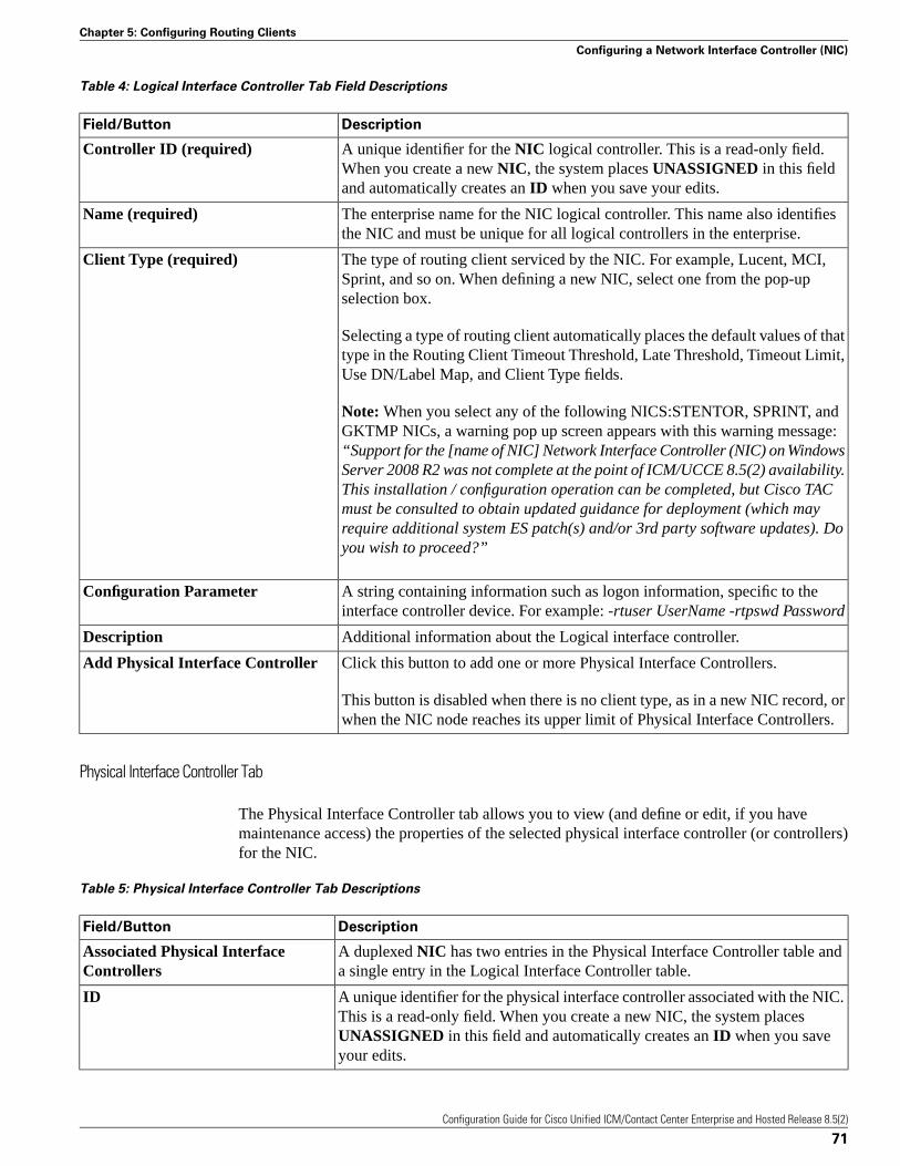
Table 4: Logical Interface Controller Tab Field Descriptions
DescriptionField/Button
A unique identifier for the NIC logical controller. This is a read-only field.When you create a new NIC, the system places UNASSIGNED in this fieldand automatically creates an ID when you save your edits.
Controller ID (required)
The enterprise name for the NIC logical controller. This name also identifiesthe NIC and must be unique for all logical controllers in the enterprise.
Name (required)
The type of routing client serviced by the NIC. For example, Lucent, MCI,Sprint, and so on. When defining a new NIC, select one from the pop-upselection box.
Client Type (required)
Selecting a type of routing client automatically places the default values of thattype in the Routing Client Timeout Threshold, Late Threshold, Timeout Limit,Use DN/Label Map, and Client Type fields.
Note: When you select any of the following NICS:STENTOR, SPRINT, andGKTMP NICs, a warning pop up screen appears with this warning message:“Support for the [name of NIC] Network Interface Controller (NIC) on WindowsServer 2008 R2 was not complete at the point of ICM/UCCE 8.5(2) availability.This installation / configuration operation can be completed, but Cisco TACmust be consulted to obtain updated guidance for deployment (which mayrequire additional system ES patch(s) and/or 3rd party software updates). Doyou wish to proceed?”
A string containing information such as logon information, specific to theinterface controller device. For example: -rtuser UserName -rtpswd Password
Configuration Parameter
Additional information about the Logical interface controller.Description
Click this button to add one or more Physical Interface Controllers.Add Physical Interface Controller
This button is disabled when there is no client type, as in a new NIC record, orwhen the NIC node reaches its upper limit of Physical Interface Controllers.
Physical Interface Controller Tab
The Physical Interface Controller tab allows you to view (and define or edit, if you havemaintenance access) the properties of the selected physical interface controller (or controllers)for the NIC.
Table 5: Physical Interface Controller Tab Descriptions
DescriptionField/Button
A duplexed NIC has two entries in the Physical Interface Controller table anda single entry in the Logical Interface Controller table.
Associated Physical InterfaceControllers
A unique identifier for the physical interface controller associated with the NIC.This is a read-only field. When you create a new NIC, the system places
ID
UNASSIGNED in this field and automatically creates an ID when you saveyour edits.
Configuration Guide for Cisco Unified ICM/Contact Center Enterprise and Hosted Release 8.5(2)
71
Chapter 5: Configuring Routing Clients
Configuring a Network Interface Controller (NIC)
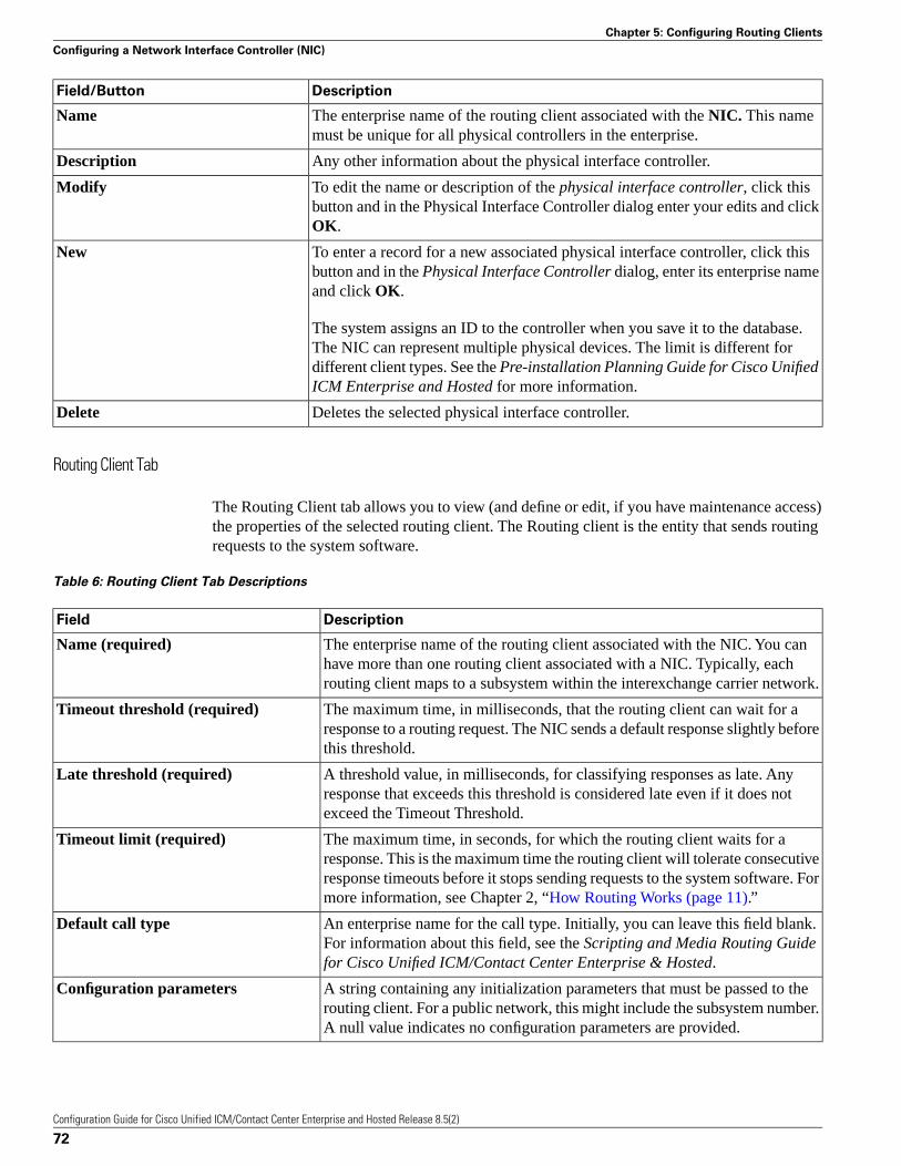
DescriptionField/Button
The enterprise name of the routing client associated with the NIC. This namemust be unique for all physical controllers in the enterprise.
Name
Any other information about the physical interface controller.Description
To edit the name or description of the physical interface controller, click thisbutton and in the Physical Interface Controller dialog enter your edits and clickOK.
Modify
To enter a record for a new associated physical interface controller, click thisbutton and in the Physical Interface Controller dialog, enter its enterprise nameand click OK.
New
The system assigns an ID to the controller when you save it to the database.The NIC can represent multiple physical devices. The limit is different fordifferent client types. See the Pre-installation Planning Guide for Cisco UnifiedICM Enterprise and Hosted for more information.
Deletes the selected physical interface controller.Delete
Routing Client Tab
The Routing Client tab allows you to view (and define or edit, if you have maintenance access)the properties of the selected routing client. The Routing client is the entity that sends routingrequests to the system software.
Table 6: Routing Client Tab Descriptions
DescriptionField
The enterprise name of the routing client associated with the NIC. You canhave more than one routing client associated with a NIC. Typically, eachrouting client maps to a subsystem within the interexchange carrier network.
Name (required)
The maximum time, in milliseconds, that the routing client can wait for aresponse to a routing request. The NIC sends a default response slightly beforethis threshold.
Timeout threshold (required)
A threshold value, in milliseconds, for classifying responses as late. Anyresponse that exceeds this threshold is considered late even if it does notexceed the Timeout Threshold.
Late threshold (required)
The maximum time, in seconds, for which the routing client waits for aresponse. This is the maximum time the routing client will tolerate consecutive
Timeout limit (required)
response timeouts before it stops sending requests to the system software. Formore information, see Chapter 2, “How Routing Works (page 11).”
An enterprise name for the call type. Initially, you can leave this field blank.For information about this field, see the Scripting and Media Routing Guidefor Cisco Unified ICM/Contact Center Enterprise & Hosted.
Default call type
A string containing any initialization parameters that must be passed to therouting client. For a public network, this might include the subsystem number.A null value indicates no configuration parameters are provided.
Configuration parameters
Configuration Guide for Cisco Unified ICM/Contact Center Enterprise and Hosted Release 8.5(2)
72
Chapter 5: Configuring Routing Clients
Configuring a Network Interface Controller (NIC)
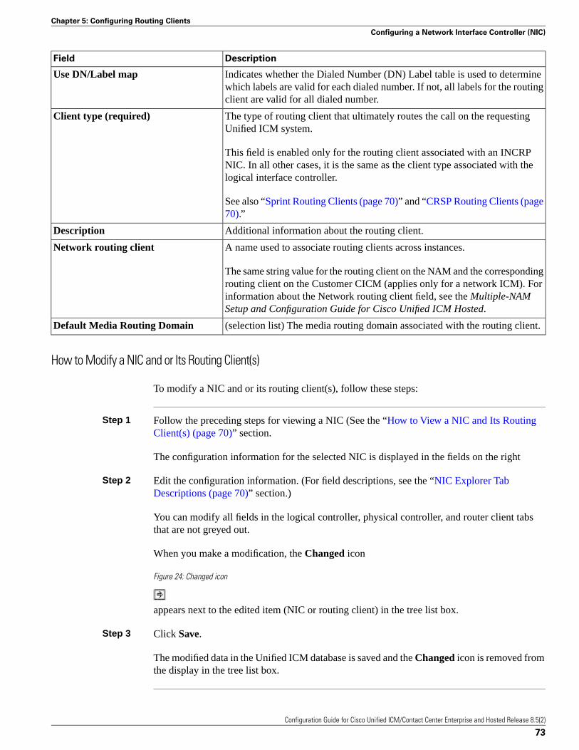
DescriptionField
Indicates whether the Dialed Number (DN) Label table is used to determinewhich labels are valid for each dialed number. If not, all labels for the routingclient are valid for all dialed number.
Use DN/Label map
The type of routing client that ultimately routes the call on the requestingUnified ICM system.
Client type (required)
This field is enabled only for the routing client associated with an INCRPNIC. In all other cases, it is the same as the client type associated with thelogical interface controller.
See also “Sprint Routing Clients (page 70)” and “CRSP Routing Clients (page70).”
Additional information about the routing client.Description
A name used to associate routing clients across instances.Network routing client
The same string value for the routing client on the NAM and the correspondingrouting client on the Customer CICM (applies only for a network ICM). Forinformation about the Network routing client field, see the Multiple-NAMSetup and Configuration Guide for Cisco Unified ICM Hosted.
(selection list) The media routing domain associated with the routing client.Default Media Routing Domain
How to Modify a NIC and or Its Routing Client(s)
To modify a NIC and or its routing client(s), follow these steps:
Step 1 Follow the preceding steps for viewing a NIC (See the “How to View a NIC and Its RoutingClient(s) (page 70)” section.
The configuration information for the selected NIC is displayed in the fields on the right
Step 2 Edit the configuration information. (For field descriptions, see the “NIC Explorer TabDescriptions (page 70)” section.)
You can modify all fields in the logical controller, physical controller, and router client tabsthat are not greyed out.
When you make a modification, the Changed icon
Figure 24: Changed icon
appears next to the edited item (NIC or routing client) in the tree list box.
Step 3 Click Save.
The modified data in the Unified ICM database is saved and the Changed icon is removed fromthe display in the tree list box.
Configuration Guide for Cisco Unified ICM/Contact Center Enterprise and Hosted Release 8.5(2)
73
Chapter 5: Configuring Routing Clients
Configuring a Network Interface Controller (NIC)
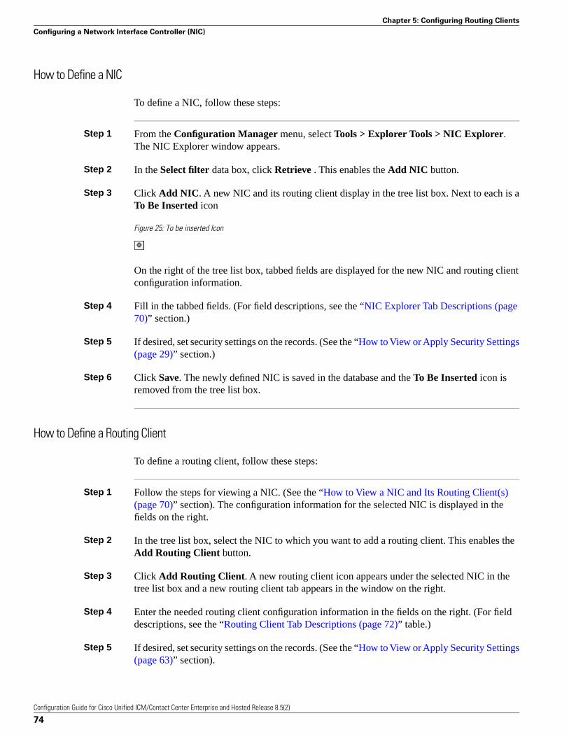
How to Define a NIC
To define a NIC, follow these steps:
Step 1 From the Configuration Manager menu, select Tools > Explorer Tools > NIC Explorer.The NIC Explorer window appears.
Step 2 In the Select filter data box, click Retrieve . This enables the Add NIC button.
Step 3 Click Add NIC. A new NIC and its routing client display in the tree list box. Next to each is aTo Be Inserted icon
Figure 25: To be inserted Icon
On the right of the tree list box, tabbed fields are displayed for the new NIC and routing clientconfiguration information.
Step 4 Fill in the tabbed fields. (For field descriptions, see the “NIC Explorer Tab Descriptions (page70)” section.)
Step 5 If desired, set security settings on the records. (See the “How to View or Apply Security Settings(page 29)” section.)
Step 6 Click Save. The newly defined NIC is saved in the database and the To Be Inserted icon isremoved from the tree list box.
How to Define a Routing Client
To define a routing client, follow these steps:
Step 1 Follow the steps for viewing a NIC. (See the “How to View a NIC and Its Routing Client(s)(page 70)” section). The configuration information for the selected NIC is displayed in thefields on the right.
Step 2 In the tree list box, select the NIC to which you want to add a routing client. This enables theAdd Routing Client button.
Step 3 Click Add Routing Client. A new routing client icon appears under the selected NIC in thetree list box and a new routing client tab appears in the window on the right.
Step 4 Enter the needed routing client configuration information in the fields on the right. (For fielddescriptions, see the “Routing Client Tab Descriptions (page 72)” table.)
Step 5 If desired, set security settings on the records. (See the “How to View or Apply Security Settings(page 63)” section).
Configuration Guide for Cisco Unified ICM/Contact Center Enterprise and Hosted Release 8.5(2)
74
Chapter 5: Configuring Routing Clients
Configuring a Network Interface Controller (NIC)
Step 6 Click Save.
Sprint Routing Clients
If you specify Sprint as the type of routing client, the NIC Explorer automatically generatessome additional records:
• An announcement named NPA_Blocked_Recording (if it does not already exist).
• A label named @NPA Blocked Recording associated with the generated routing client. Thelabel type is Normal and the target is the NPA_Blocked_Recording announcement.
• A label named @Slow Busy associated with the generated routing client. The label type isBusy.
These records provide support for the Sprint NPA Blocked Recording feature and for returninga busy signal to the caller.
CRSP Routing Clients
CRSP. If you specify CRSP as the type of routing client, two labels are automatically createdby the NIC Explorer and are associated with the new routing client:
• “ringForever” with a label type of 3 (ring)
• “busyForver” with a label type of 2 (busy)
When a CRSP routing client record is deleted, the preceding labels associated with the routingclient are also deleted.
How to Delete a NIC
Follow these steps to delete a NIC:
Step 1 Follow the steps for viewing a NIC. (See the “How to View a NIC and Its Routing Client(s)(page 70)” section.)
The configuration information for the selected NIC is displayed in the fields on the right.
Step 2 In the tree list box, select the NIC whose records you want to delete.
Step 3 Click Delete. This places a Marked for Deletion icon
Figure 26: Marked for deletion icon
Configuration Guide for Cisco Unified ICM/Contact Center Enterprise and Hosted Release 8.5(2)
75
Chapter 5: Configuring Routing Clients
Configuring a Network Interface Controller (NIC)
next to the NIC in the tree list box. This also toggles the Delete button to Undelete.
To undelete a NIC marked for deletion, select it in the tree list box and click Undelete.
Step 4 Click Save.
This deletes from the database the NIC marked for deletion and removes it from the tree listbox. Once you do this, you cannot undelete the NIC.
Configuring Dialed Number/Script Selectors
After you have set up a routing client, you need to define the dialed number/script selectorsserviced by it. A dialed number/script selector can represent an actual number dialed by a calleror any string passed by a routing client to indicate the number dialed.
The Configuration Manager Dialed Number/Script Selector List tool allows you to list the dialednumber/script selectors currently defined in the Unified ICM database, to define new ones, andto view, edit, or delete the records of existing ones. The following instructions show you howto configure individual dialed number/script selectors. For configuring multiple dialednumber/script selectors at a time, see Chapter 4, “Configuring Multiple Records at a Time (page83).”
Dialed Number/Script Selector List Tab Descriptions
How to View, Define, Delete, or Modify Dialed Number/Script Selectors
Note: The “Configuring Dialed Numbers on the Child Central Controller (page 77)” sectioncontains an example of how to configure dialed numbers on a child deployment, which isdocumented in the Cisco Contact Center Gateway Deployment Guide for Cisco UnifiedICME/CCE/CCX.
Use the following steps to view, define, delete, or modify dialed number/script selectors:
Step 1 From within the Configuration Manager menu, select Tools > List Tools > DialedNumber/Script Selector List. The Dialed Number/Script Selector List window appears.
Step 2 In the Select filter data area, select the Routing client and Customer associated with the dialednumber/script selector.
Note: Once you have saved a Dialed Number record to the Unified ICM database, you cannotupdate the Routing Client field.
If you are viewing or modifying a previously created record and you want to limit the numberof records retrieved from the database, also select one of the optional filters.
Configuration Guide for Cisco Unified ICM/Contact Center Enterprise and Hosted Release 8.5(2)
76
Chapter 5: Configuring Routing Clients
Configuring Dialed Number/Script Selectors
Step 3 Click Retrieve. This enables the Add button and displays a list of the retrieved dialednumber/script selectors.
The properties of the dialed number/script selector selected in the Dialed Number/Script Selectorlist box on the left side of the window are displayed in the property tabs on the right side of thewindow:
The following properties are displayed:
• The Attributes tab allows you to view and (if you have maintenance access) to define, edit,or delete the attributes of the selected dialed number/script selector. Attributes with an asteriskare required. Table “Dialed Number/Script Selector Attributes Tab Descriptions” (page 78)describes these attributes.
• The Dialed Number Label tab allows you to map labels (in addition to a default label) to theselected dialed number/script selector. The “Dialed Number Label Tab Descriptions (page78)” table describes the fields and buttons on this tab.
Step 4 This step depends on what you want to do:
• To add a new dialed number/script selector, click Add and enter the appropriate values inthe tabbed property fields on the right side of the window.
• To delete a dialed number/script selector, select that number in the Dialed Number/ScriptSelector list box and click Delete.
• To edit a dialed number/script selector, select that number in the Dialed Number/ScriptSelector list box and edit the appropriate values in the tabbed property fields on the rightside of the window.
Step 5 Click Save to enter any edits into the database.
The dialog closes, and for a new dialed number/script selector, the Unified ICM databasemanager automatically generates a unique Dialed Number ID for the routing client.
Configuring Dialed Numbers on the Child Central Controller
Access the Configuration Manager on the Child Administration & Data Server to configuredialed numbers.
How to Configure Dialed Numbers on the Child Central Controller
Use the Configuration Manager Dialed Number/Script Selector List Tool to configure dialednumbers on the Child Central Controller.
Step 1 Start the Dialed Number/Script Selector List Tool.
Step 2 On the Main window of the Dialed Number/Script Selector List Tool, click Retrieve.
Configuration Guide for Cisco Unified ICM/Contact Center Enterprise and Hosted Release 8.5(2)
77
Chapter 5: Configuring Routing Clients
Configuring Dialed Number/Script Selectors
Step 3 Click Add.
The Dialed Number Attributes tab appears.
Step 4 Select IPCC_RC as the Routing Client.
Step 5 Select Cisco_Voice for the Media Routing Domain.
Step 6 Set the Dialed Number String/Script Selector to 2500 (the route point set up on the Unified CM.
Step 7 Set IPCC_RC_2500 as the Name, then select bh03 as the Customer setting.
Step 8 Check Permit Application Routing on the route points controlled by the Parent (the Post routepoints and the Translation route points).
This provides the link between the Parent and the Child. It gives the Parent visibility to theDialed Number so it is able to handle it.
Step 9 Click Save.
The dialed number appears in the tree list.
Step 10 Repeat this to add two more dialed numbers (one for each skill group).
When complete, you have the following DNs:
• 2500
– Connects to all of the skill groups.
– Named IPCC_RC_2500.
• 2501
– Connects to SG01.
– Named IPCC_RC_2501.
• 2502
– Connects to SG02.
– Named IPCC_RC_2502.
Step 11 Click Save, then Close to exit the Skill Group Explorer Tool.
Dialed Number/Script Selector List Tab Descriptions
The following tables describe the tabbed property fields and buttons that configure a dialednumber record.
Configuration Guide for Cisco Unified ICM/Contact Center Enterprise and Hosted Release 8.5(2)
78
Chapter 5: Configuring Routing Clients
Configuring Dialed Number/Script Selectors
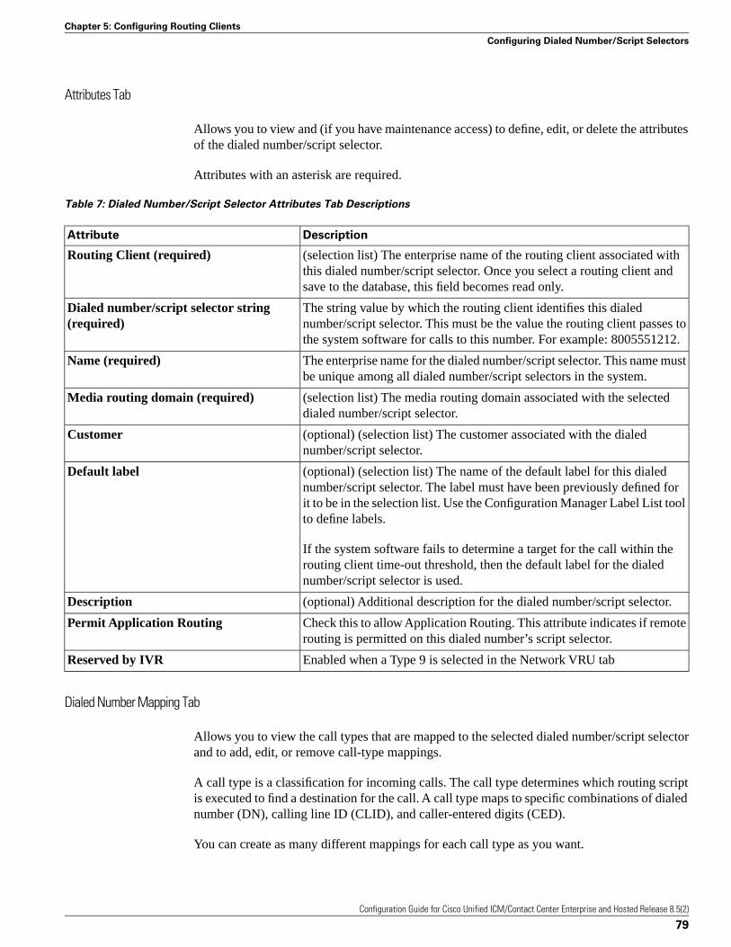
Attributes Tab
Allows you to view and (if you have maintenance access) to define, edit, or delete the attributesof the dialed number/script selector.
Attributes with an asterisk are required.
Table 7: Dialed Number/Script Selector Attributes Tab Descriptions
DescriptionAttribute
(selection list) The enterprise name of the routing client associated withthis dialed number/script selector. Once you select a routing client andsave to the database, this field becomes read only.
Routing Client (required)
The string value by which the routing client identifies this dialednumber/script selector. This must be the value the routing client passes tothe system software for calls to this number. For example: 8005551212.
Dialed number/script selector string(required)
The enterprise name for the dialed number/script selector. This name mustbe unique among all dialed number/script selectors in the system.
Name (required)
(selection list) The media routing domain associated with the selecteddialed number/script selector.
Media routing domain (required)
(optional) (selection list) The customer associated with the dialednumber/script selector.
Customer
(optional) (selection list) The name of the default label for this dialednumber/script selector. The label must have been previously defined for
Default label
it to be in the selection list. Use the Configuration Manager Label List toolto define labels.
If the system software fails to determine a target for the call within therouting client time-out threshold, then the default label for the dialednumber/script selector is used.
(optional) Additional description for the dialed number/script selector.Description
Check this to allow Application Routing. This attribute indicates if remoterouting is permitted on this dialed number’s script selector.
Permit Application Routing
Enabled when a Type 9 is selected in the Network VRU tabReserved by IVR
Dialed Number Mapping Tab
Allows you to view the call types that are mapped to the selected dialed number/script selectorand to add, edit, or remove call-type mappings.
A call type is a classification for incoming calls. The call type determines which routing scriptis executed to find a destination for the call. A call type maps to specific combinations of dialednumber (DN), calling line ID (CLID), and caller-entered digits (CED).
You can create as many different mappings for each call type as you want.
Configuration Guide for Cisco Unified ICM/Contact Center Enterprise and Hosted Release 8.5(2)
79
Chapter 5: Configuring Routing Clients
Configuring Dialed Number/Script Selectors
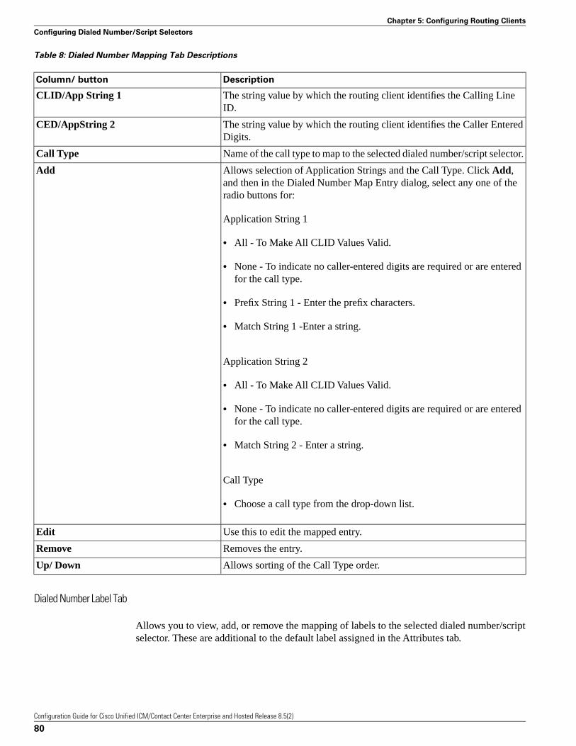
Table 8: Dialed Number Mapping Tab Descriptions
DescriptionColumn/ button
The string value by which the routing client identifies the Calling LineID.
CLID/App String 1
The string value by which the routing client identifies the Caller EnteredDigits.
CED/AppString 2
Name of the call type to map to the selected dialed number/script selector.Call Type
Allows selection of Application Strings and the Call Type. Click Add,and then in the Dialed Number Map Entry dialog, select any one of theradio buttons for:
Add
Application String 1
• All - To Make All CLID Values Valid.
• None - To indicate no caller-entered digits are required or are enteredfor the call type.
• Prefix String 1 - Enter the prefix characters.
• Match String 1 -Enter a string.
Application String 2
• All - To Make All CLID Values Valid.
• None - To indicate no caller-entered digits are required or are enteredfor the call type.
• Match String 2 - Enter a string.
Call Type
• Choose a call type from the drop-down list.
Use this to edit the mapped entry.Edit
Removes the entry.Remove
Allows sorting of the Call Type order.Up/ Down
Dialed Number Label Tab
Allows you to view, add, or remove the mapping of labels to the selected dialed number/scriptselector. These are additional to the default label assigned in the Attributes tab.
Configuration Guide for Cisco Unified ICM/Contact Center Enterprise and Hosted Release 8.5(2)
80
Chapter 5: Configuring Routing Clients
Configuring Dialed Number/Script Selectors
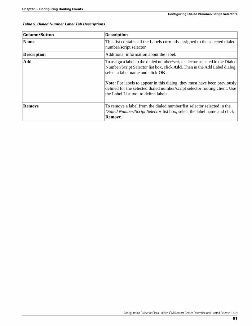
Table 9: Dialed Number Label Tab Descriptions
DescriptionColumn/Button
This list contains all the Labels currently assigned to the selected dialednumber/script selector.
Name
Additional information about the label.Description
To assign a label to the dialed number/script selector selected in the DialedNumber/Script Selector list box, click Add. Then in the Add Label dialog,select a label name and click OK.
Add
Note: For labels to appear in this dialog, they must have been previouslydefined for the selected dialed number/script selector routing client. Usethe Label List tool to define labels.
To remove a label from the dialed number/list selector selected in theDialed Number/Script Selector list box, select the label name and clickRemove.
Remove
Configuration Guide for Cisco Unified ICM/Contact Center Enterprise and Hosted Release 8.5(2)
81
Chapter 5: Configuring Routing Clients
Configuring Dialed Number/Script Selectors

Configuration Guide for Cisco Unified ICM/Contact Center Enterprise and Hosted Release 8.5(2)
82
Chapter 5: Configuring Routing Clients
Configuring Dialed Number/Script Selectors
Configuring Peripherals and Trunk GroupsThis chapter describes how to configure peripherals and the trunk groups associated with them.
It includes:
• An introduction to the Peripheral Subsystem
• Instructions on how to view, define, delete, or modify:
– Peripheral Gateways
– Peripherals
– Network Trunk Groups
– Trunk Groups
– Trunks
Note: See Appendix A, “Peripheral Terminology (page 223),” for more details.
This chapter contains the following topics:
• The Peripheral Subsystem, page 84• Peripheral Gateways, page 84• Configuring a Peripheral Gateway, page 85• Configuring Trunk Groups and Trunks, page 103
Configuration Guide for Cisco Unified ICM/Contact Center Enterprise and Hosted Release 8.5(2)
83
Chapter 6
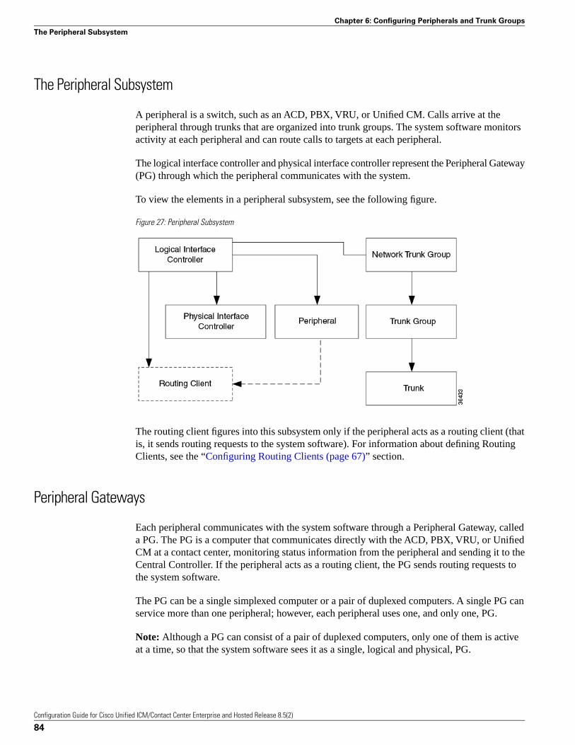
The Peripheral Subsystem
A peripheral is a switch, such as an ACD, PBX, VRU, or Unified CM. Calls arrive at theperipheral through trunks that are organized into trunk groups. The system software monitorsactivity at each peripheral and can route calls to targets at each peripheral.
The logical interface controller and physical interface controller represent the Peripheral Gateway(PG) through which the peripheral communicates with the system.
To view the elements in a peripheral subsystem, see the following figure.
Figure 27: Peripheral Subsystem
The routing client figures into this subsystem only if the peripheral acts as a routing client (thatis, it sends routing requests to the system software). For information about defining RoutingClients, see the “Configuring Routing Clients (page 67)” section.
Peripheral Gateways
Each peripheral communicates with the system software through a Peripheral Gateway, calleda PG. The PG is a computer that communicates directly with the ACD, PBX, VRU, or UnifiedCM at a contact center, monitoring status information from the peripheral and sending it to theCentral Controller. If the peripheral acts as a routing client, the PG sends routing requests tothe system software.
The PG can be a single simplexed computer or a pair of duplexed computers. A single PG canservice more than one peripheral; however, each peripheral uses one, and only one, PG.
Note: Although a PG can consist of a pair of duplexed computers, only one of them is activeat a time, so that the system software sees it as a single, logical and physical, PG.
Configuration Guide for Cisco Unified ICM/Contact Center Enterprise and Hosted Release 8.5(2)
84
Chapter 6: Configuring Peripherals and Trunk Groups
The Peripheral Subsystem
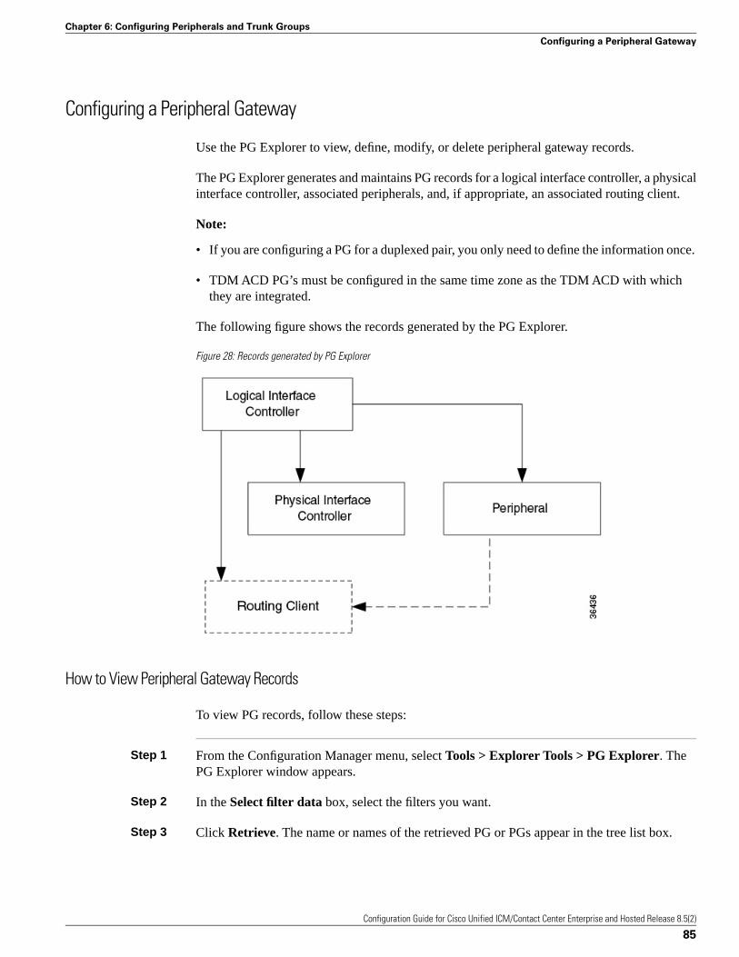
Configuring a Peripheral Gateway
Use the PG Explorer to view, define, modify, or delete peripheral gateway records.
The PG Explorer generates and maintains PG records for a logical interface controller, a physicalinterface controller, associated peripherals, and, if appropriate, an associated routing client.
Note:
• If you are configuring a PG for a duplexed pair, you only need to define the information once.
• TDM ACD PG’s must be configured in the same time zone as the TDM ACD with whichthey are integrated.
The following figure shows the records generated by the PG Explorer.
Figure 28: Records generated by PG Explorer
How to View Peripheral Gateway Records
To view PG records, follow these steps:
Step 1 From the Configuration Manager menu, select Tools > Explorer Tools > PG Explorer. ThePG Explorer window appears.
Step 2 In the Select filter data box, select the filters you want.
Step 3 Click Retrieve. The name or names of the retrieved PG or PGs appear in the tree list box.
Configuration Guide for Cisco Unified ICM/Contact Center Enterprise and Hosted Release 8.5(2)
85
Chapter 6: Configuring Peripherals and Trunk Groups
Configuring a Peripheral Gateway
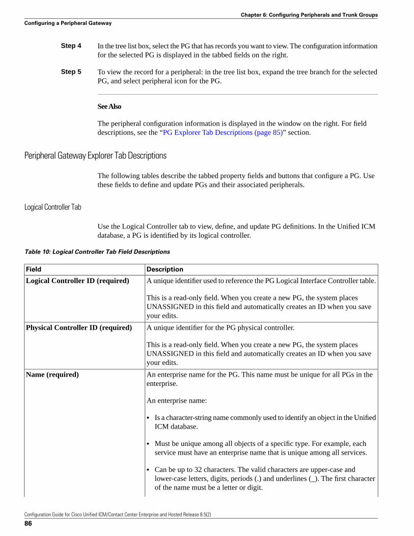
Step 4 In the tree list box, select the PG that has records you want to view. The configuration informationfor the selected PG is displayed in the tabbed fields on the right.
Step 5 To view the record for a peripheral: in the tree list box, expand the tree branch for the selectedPG, and select peripheral icon for the PG.
See Also
The peripheral configuration information is displayed in the window on the right. For fielddescriptions, see the “PG Explorer Tab Descriptions (page 85)” section.
Peripheral Gateway Explorer Tab Descriptions
The following tables describe the tabbed property fields and buttons that configure a PG. Usethese fields to define and update PGs and their associated peripherals.
Logical Controller Tab
Use the Logical Controller tab to view, define, and update PG definitions. In the Unified ICMdatabase, a PG is identified by its logical controller.
Table 10: Logical Controller Tab Field Descriptions
DescriptionField
A unique identifier used to reference the PG Logical Interface Controller table.Logical Controller ID (required)
This is a read-only field. When you create a new PG, the system placesUNASSIGNED in this field and automatically creates an ID when you saveyour edits.
A unique identifier for the PG physical controller.Physical Controller ID (required)
This is a read-only field. When you create a new PG, the system placesUNASSIGNED in this field and automatically creates an ID when you saveyour edits.
An enterprise name for the PG. This name must be unique for all PGs in theenterprise.
Name (required)
An enterprise name:
• Is a character-string name commonly used to identify an object in the UnifiedICM database.
• Must be unique among all objects of a specific type. For example, eachservice must have an enterprise name that is unique among all services.
• Can be up to 32 characters. The valid characters are upper-case andlower-case letters, digits, periods (.) and underlines (_). The first characterof the name must be a letter or digit.
Configuration Guide for Cisco Unified ICM/Contact Center Enterprise and Hosted Release 8.5(2)
86
Chapter 6: Configuring Peripherals and Trunk Groups
Configuring a Peripheral Gateway
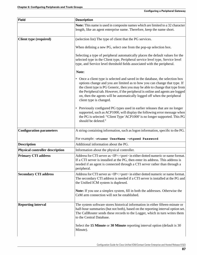
DescriptionField
Note: This name is used in composite names which are limited to a 32 characterlength, like an agent enterprise name. Therefore, keep the name short.
(selection list) The type of client that the PG services.Client type (required)
When defining a new PG, select one from the pop-up selection box.
Selecting a type of peripheral automatically places the default values for theselected type in the Client type, Peripheral service level type, Service leveltype, and Service level threshold fields associated with the peripheral.
Note:
• Once a client type is selected and saved in the database, the selection boxoptions change and you are limited as to how you can change that type. Ifthe client type is PG Generic, then you may be able to change that type fromthe Peripheral tab. However, if the peripheral is online and agents are loggedon, then the agents will be automatically logged off when the peripheralclient type is changed.
• Previously configured PG types used in earlier releases that are no longersupported, such as ACP1000, will display the following error message whenthe PG is selected: “Client Type 'ACP1000' is no longer supported. This PGshould be deleted.”
A string containing information, such as logon information, specific to the PG.Configuration parameters
For example: -rtuser UserName -rtpswd Password
Additional information about the PG.Description
Information about the physical controller.Physical controller description
Address for CTI server as <IP>:<port> in either dotted numeric or name format.If a CTI server is installed at the PG, then enter its address. This address is
Primary CTI address
needed if an agent is connected through a CTI server rather than through aperipheral.
Address for CTI server as <IP>:<port> in either dotted numeric or name format.The secondary CTI address is needed if a CTI server is installed at the PG andthe Unified ICM system is duplexed.
Secondary CTI address
Note: If you use a simplex system, fill in both the addresses. Otherwise theCeM arm connection will not be established.
The system software stores historical information in either fifteen-minute orhalf-hour summaries (but not both), based on the reporting interval option set.
Reporting interval
The CallRouter sends these records to the Logger, which in turn writes themto the Central Database.
Select the 15 Minute or 30 Minute reporting interval option (default is 30Minute).
Configuration Guide for Cisco Unified ICM/Contact Center Enterprise and Hosted Release 8.5(2)
87
Chapter 6: Configuring Peripherals and Trunk Groups
Configuring a Peripheral Gateway
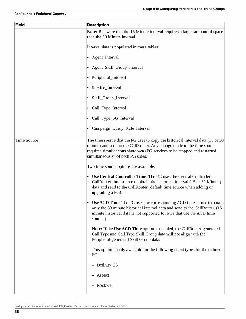
DescriptionField
Note: Be aware that the 15 Minute interval requires a larger amount of spacethan the 30 Minute interval.
Interval data is populated in these tables:
• Agent_Interval
• Agent_Skill_Group_Interval
• Peripheral_Interval
• Service_Interval
• Skill_Group_Interval
• Call_Type_Interval
• Call_Type_SG_Interval
• Campaign_Query_Rule_Interval
The time source that the PG uses to copy the historical interval data (15 or 30minute) and send to the CallRouter. Any change made to the time source
Time Source
requires simultaneous shutdown (PG services to be stopped and restartedsimultaneously) of both PG sides.
Two time source options are available:
• Use Central Controller Time. The PG uses the Central ControllerCallRouter time source to obtain the historical interval (15 or 30 Minute)data and send to the CallRouter (default time source when adding orupgrading a PG).
• Use ACD Time. The PG uses the corresponding ACD time source to obtainonly the 30 minute historical interval data and send to the CallRouter. (15minute historical data is not supported for PGs that use the ACD timesource.)
Note: If the Use ACD Time option is enabled, the CallRouter-generatedCall Type and Call Type Skill Group data will not align with thePeripheral-generated Skill Group data.
This option is only available for the following client types for the definedPG:
– Definity G3
– Aspect
– Rockwell
Configuration Guide for Cisco Unified ICM/Contact Center Enterprise and Hosted Release 8.5(2)
88
Chapter 6: Configuring Peripherals and Trunk Groups
Configuring a Peripheral Gateway
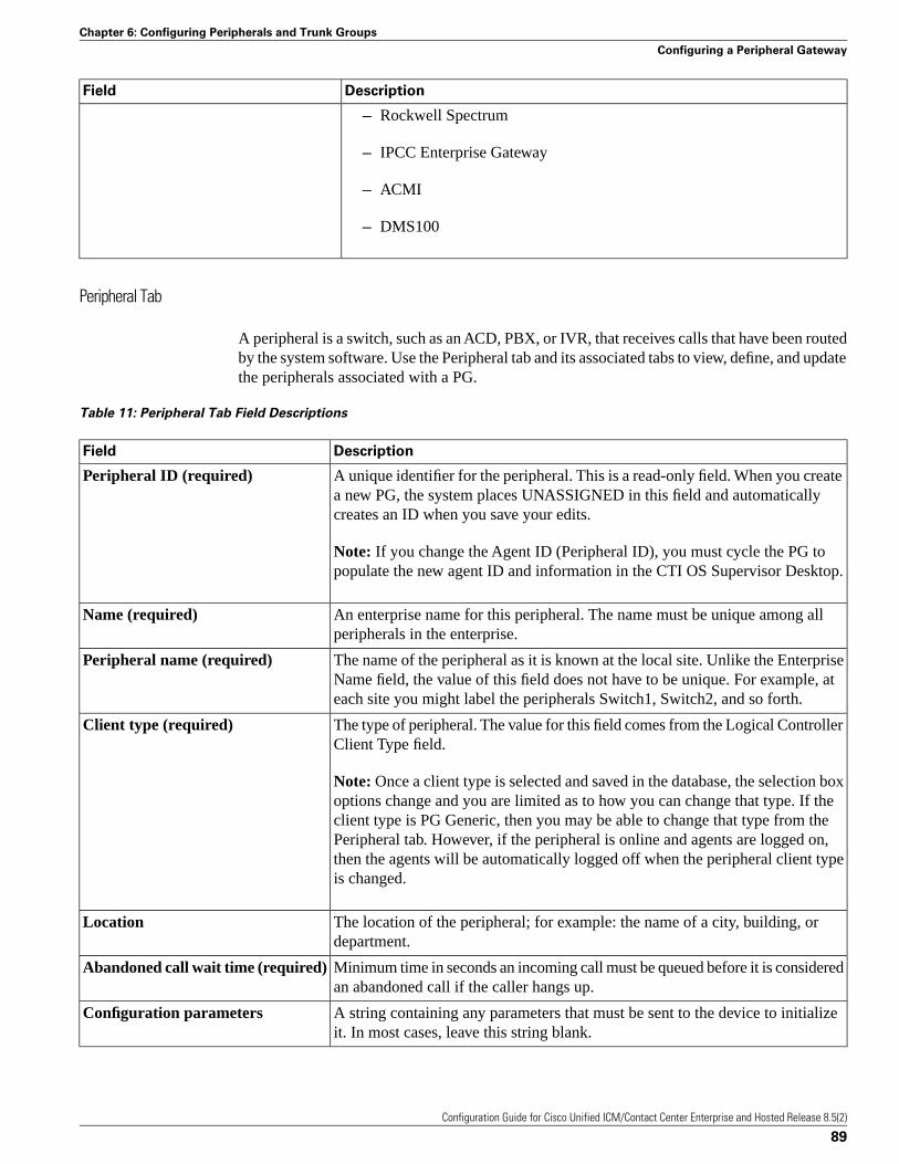
DescriptionField
– Rockwell Spectrum
– IPCC Enterprise Gateway
– ACMI
– DMS100
Peripheral Tab
A peripheral is a switch, such as an ACD, PBX, or IVR, that receives calls that have been routedby the system software. Use the Peripheral tab and its associated tabs to view, define, and updatethe peripherals associated with a PG.
Table 11: Peripheral Tab Field Descriptions
DescriptionField
A unique identifier for the peripheral. This is a read-only field. When you createa new PG, the system places UNASSIGNED in this field and automaticallycreates an ID when you save your edits.
Peripheral ID (required)
Note: If you change the Agent ID (Peripheral ID), you must cycle the PG topopulate the new agent ID and information in the CTI OS Supervisor Desktop.
An enterprise name for this peripheral. The name must be unique among allperipherals in the enterprise.
Name (required)
The name of the peripheral as it is known at the local site. Unlike the EnterpriseName field, the value of this field does not have to be unique. For example, ateach site you might label the peripherals Switch1, Switch2, and so forth.
Peripheral name (required)
The type of peripheral. The value for this field comes from the Logical ControllerClient Type field.
Client type (required)
Note: Once a client type is selected and saved in the database, the selection boxoptions change and you are limited as to how you can change that type. If theclient type is PG Generic, then you may be able to change that type from thePeripheral tab. However, if the peripheral is online and agents are logged on,then the agents will be automatically logged off when the peripheral client typeis changed.
The location of the peripheral; for example: the name of a city, building, ordepartment.
Location
Minimum time in seconds an incoming call must be queued before it is consideredan abandoned call if the caller hangs up.
Abandoned call wait time (required)
A string containing any parameters that must be sent to the device to initializeit. In most cases, leave this string blank.
Configuration parameters
Configuration Guide for Cisco Unified ICM/Contact Center Enterprise and Hosted Release 8.5(2)
89
Chapter 6: Configuring Peripherals and Trunk Groups
Configuring a Peripheral Gateway
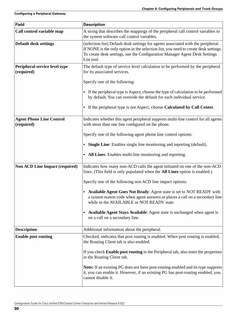
DescriptionField
A string that describes the mappings of the peripheral call control variables tothe system software call control variables.
Call control variable map
(selection list) Default desk settings for agents associated with the peripheral.If NONE is the only option in the selection list, you need to create desk settings.
Default desk settings
To create desk settings, use the Configuration Manager Agent Desk SettingsList tool.
The default type of service level calculation to be performed by the peripheralfor its associated services.
Peripheral service level type(required)
Specify one of the following:
• If the peripheral type is Aspect, choose the type of calculation to be performedby default. You can override the default for each individual service.
• If the peripheral type is not Aspect, choose Calculated by Call Center.
Indicates whether this agent peripheral supports multi-line control for all agentswith more than one line configured on the phone.
Agent Phone Line Control(required)
Specify one of the following agent phone line control options:
• Single Line: Enables single line monitoring and reporting (default).
• All Lines: Enables multi-line monitoring and reporting.
Indicates how many non-ACD calls the agent initiated on one of the non-ACDlines. (This field is only populated when the All Lines option is enabled.)
Non ACD Line Impact (required)
Specify one of the following non ACD line impact options:
• Available Agent Goes Not Ready: Agent state is set to NOT READY witha system reason code when agent answers or places a call on a secondary linewhile in the AVAILABLE or NOT READY state.
• Available Agent Stays Available: Agent state is unchanged when agent ison a call on a secondary line.
Additional information about the peripheral.Description
Checked, indicates that post routing is enabled. When post routing is enabled,the Routing Client tab is also enabled.
Enable post routing
If you check Enable post routing in the Peripheral tab, also enter the propertiesin the Routing Client tab.
Note: If an existing PG does not have post-routing enabled and its type supportsit, you can enable it. However, if an existing PG has post-routing enabled, youcannot disable it.
Configuration Guide for Cisco Unified ICM/Contact Center Enterprise and Hosted Release 8.5(2)
90
Chapter 6: Configuring Peripherals and Trunk Groups
Configuring a Peripheral Gateway
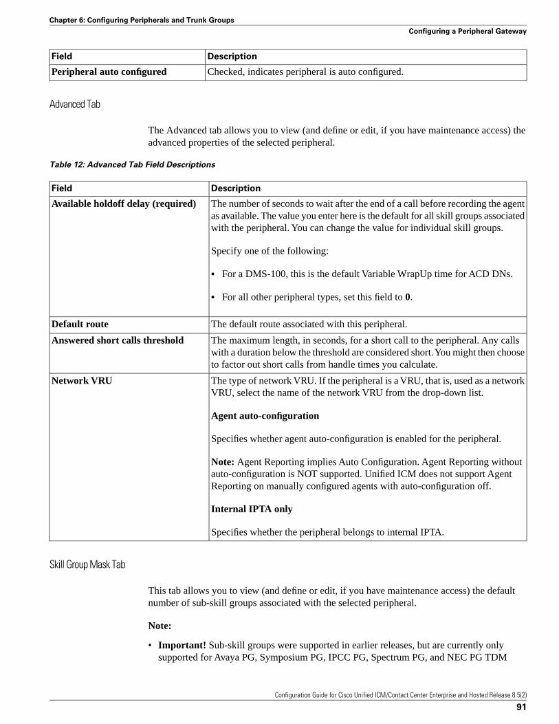
DescriptionField
Checked, indicates peripheral is auto configured.Peripheral auto configured
Advanced Tab
The Advanced tab allows you to view (and define or edit, if you have maintenance access) theadvanced properties of the selected peripheral.
Table 12: Advanced Tab Field Descriptions
DescriptionField
The number of seconds to wait after the end of a call before recording the agentas available. The value you enter here is the default for all skill groups associatedwith the peripheral. You can change the value for individual skill groups.
Available holdoff delay (required)
Specify one of the following:
• For a DMS-100, this is the default Variable WrapUp time for ACD DNs.
• For all other peripheral types, set this field to 0.
The default route associated with this peripheral.Default route
The maximum length, in seconds, for a short call to the peripheral. Any callswith a duration below the threshold are considered short. You might then chooseto factor out short calls from handle times you calculate.
Answered short calls threshold
The type of network VRU. If the peripheral is a VRU, that is, used as a networkVRU, select the name of the network VRU from the drop-down list.
Network VRU
Agent auto-configuration
Specifies whether agent auto-configuration is enabled for the peripheral.
Note: Agent Reporting implies Auto Configuration. Agent Reporting withoutauto-configuration is NOT supported. Unified ICM does not support AgentReporting on manually configured agents with auto-configuration off.
Internal IPTA only
Specifies whether the peripheral belongs to internal IPTA.
Skill Group Mask Tab
This tab allows you to view (and define or edit, if you have maintenance access) the defaultnumber of sub-skill groups associated with the selected peripheral.
Note:
• Important! Sub-skill groups were supported in earlier releases, but are currently onlysupported for Avaya PG, Symposium PG, IPCC PG, Spectrum PG, and NEC PG TDM
Configuration Guide for Cisco Unified ICM/Contact Center Enterprise and Hosted Release 8.5(2)
91
Chapter 6: Configuring Peripherals and Trunk Groups
Configuring a Peripheral Gateway
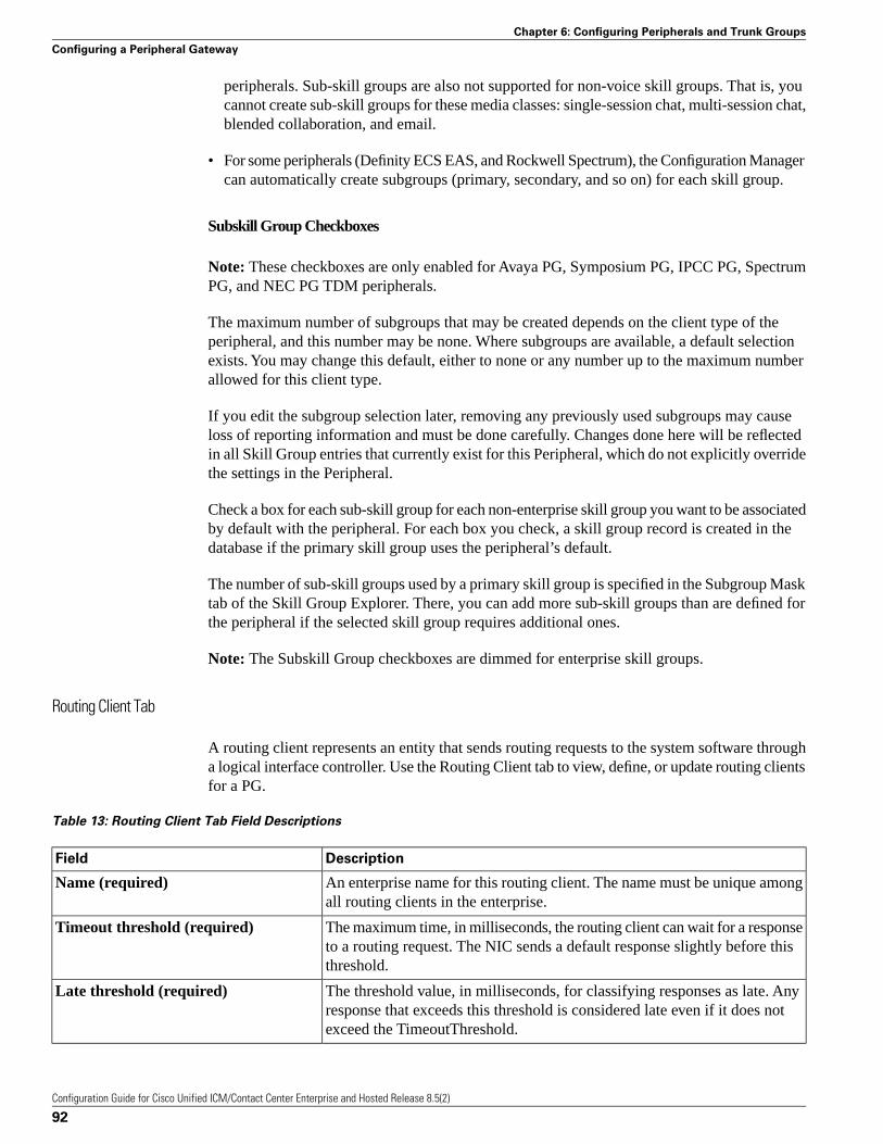
peripherals. Sub-skill groups are also not supported for non-voice skill groups. That is, youcannot create sub-skill groups for these media classes: single-session chat, multi-session chat,blended collaboration, and email.
• For some peripherals (Definity ECS EAS, and Rockwell Spectrum), the Configuration Managercan automatically create subgroups (primary, secondary, and so on) for each skill group.
Subskill Group Checkboxes
Note: These checkboxes are only enabled for Avaya PG, Symposium PG, IPCC PG, SpectrumPG, and NEC PG TDM peripherals.
The maximum number of subgroups that may be created depends on the client type of theperipheral, and this number may be none. Where subgroups are available, a default selectionexists. You may change this default, either to none or any number up to the maximum numberallowed for this client type.
If you edit the subgroup selection later, removing any previously used subgroups may causeloss of reporting information and must be done carefully. Changes done here will be reflectedin all Skill Group entries that currently exist for this Peripheral, which do not explicitly overridethe settings in the Peripheral.
Check a box for each sub-skill group for each non-enterprise skill group you want to be associatedby default with the peripheral. For each box you check, a skill group record is created in thedatabase if the primary skill group uses the peripheral’s default.
The number of sub-skill groups used by a primary skill group is specified in the Subgroup Masktab of the Skill Group Explorer. There, you can add more sub-skill groups than are defined forthe peripheral if the selected skill group requires additional ones.
Note: The Subskill Group checkboxes are dimmed for enterprise skill groups.
Routing Client Tab
A routing client represents an entity that sends routing requests to the system software througha logical interface controller. Use the Routing Client tab to view, define, or update routing clientsfor a PG.
Table 13: Routing Client Tab Field Descriptions
DescriptionField
An enterprise name for this routing client. The name must be unique amongall routing clients in the enterprise.
Name (required)
The maximum time, in milliseconds, the routing client can wait for a responseto a routing request. The NIC sends a default response slightly before thisthreshold.
Timeout threshold (required)
The threshold value, in milliseconds, for classifying responses as late. Anyresponse that exceeds this threshold is considered late even if it does notexceed the TimeoutThreshold.
Late threshold (required)
Configuration Guide for Cisco Unified ICM/Contact Center Enterprise and Hosted Release 8.5(2)
92
Chapter 6: Configuring Peripherals and Trunk Groups
Configuring a Peripheral Gateway
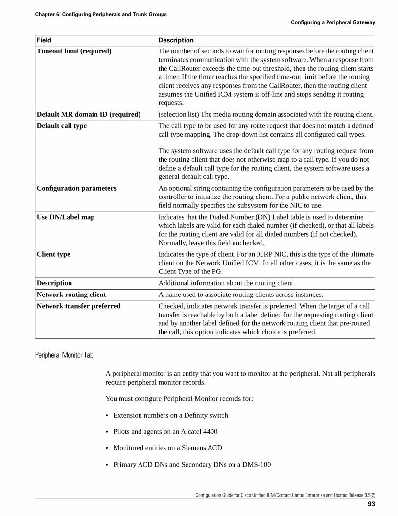
DescriptionField
The number of seconds to wait for routing responses before the routing clientterminates communication with the system software. When a response from
Timeout limit (required)
the CallRouter exceeds the time-out threshold, then the routing client startsa timer. If the timer reaches the specified time-out limit before the routingclient receives any responses from the CallRouter, then the routing clientassumes the Unified ICM system is off-line and stops sending it routingrequests.
(selection list) The media routing domain associated with the routing client.Default MR domain ID (required)
The call type to be used for any route request that does not match a definedcall type mapping. The drop-down list contains all configured call types.
Default call type
The system software uses the default call type for any routing request fromthe routing client that does not otherwise map to a call type. If you do notdefine a default call type for the routing client, the system software uses ageneral default call type.
An optional string containing the configuration parameters to be used by thecontroller to initialize the routing client. For a public network client, thisfield normally specifies the subsystem for the NIC to use.
Configuration parameters
Indicates that the Dialed Number (DN) Label table is used to determinewhich labels are valid for each dialed number (if checked), or that all labels
Use DN/Label map
for the routing client are valid for all dialed numbers (if not checked).Normally, leave this field unchecked.
Indicates the type of client. For an ICRP NIC, this is the type of the ultimateclient on the Network Unified ICM. In all other cases, it is the same as theClient Type of the PG.
Client type
Additional information about the routing client.Description
A name used to associate routing clients across instances.Network routing client
Checked, indicates network transfer is preferred. When the target of a calltransfer is reachable by both a label defined for the requesting routing client
Network transfer preferred
and by another label defined for the network routing client that pre-routedthe call, this option indicates which choice is preferred.
Peripheral Monitor Tab
A peripheral monitor is an entity that you want to monitor at the peripheral. Not all peripheralsrequire peripheral monitor records.
You must configure Peripheral Monitor records for:
• Extension numbers on a Definity switch
• Pilots and agents on an Alcatel 4400
• Monitored entities on a Siemens ACD
• Primary ACD DNs and Secondary DNs on a DMS-100
Configuration Guide for Cisco Unified ICM/Contact Center Enterprise and Hosted Release 8.5(2)
93
Chapter 6: Configuring Peripherals and Trunk Groups
Configuring a Peripheral Gateway
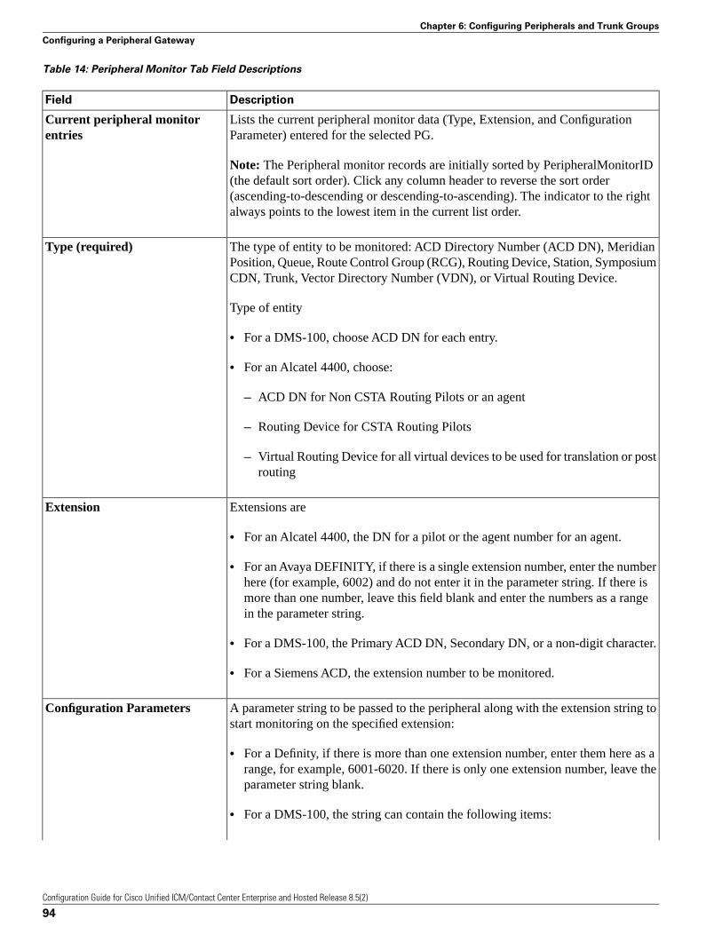
Table 14: Peripheral Monitor Tab Field Descriptions
DescriptionField
Lists the current peripheral monitor data (Type, Extension, and ConfigurationParameter) entered for the selected PG.
Current peripheral monitorentries
Note: The Peripheral monitor records are initially sorted by PeripheralMonitorID(the default sort order). Click any column header to reverse the sort order(ascending-to-descending or descending-to-ascending). The indicator to the rightalways points to the lowest item in the current list order.
The type of entity to be monitored: ACD Directory Number (ACD DN), MeridianPosition, Queue, Route Control Group (RCG), Routing Device, Station, SymposiumCDN, Trunk, Vector Directory Number (VDN), or Virtual Routing Device.
Type (required)
Type of entity
• For a DMS-100, choose ACD DN for each entry.
• For an Alcatel 4400, choose:
– ACD DN for Non CSTA Routing Pilots or an agent
– Routing Device for CSTA Routing Pilots
– Virtual Routing Device for all virtual devices to be used for translation or postrouting
Extensions areExtension
• For an Alcatel 4400, the DN for a pilot or the agent number for an agent.
• For an Avaya DEFINITY, if there is a single extension number, enter the numberhere (for example, 6002) and do not enter it in the parameter string. If there ismore than one number, leave this field blank and enter the numbers as a rangein the parameter string.
• For a DMS-100, the Primary ACD DN, Secondary DN, or a non-digit character.
• For a Siemens ACD, the extension number to be monitored.
A parameter string to be passed to the peripheral along with the extension string tostart monitoring on the specified extension:
Configuration Parameters
• For a Definity, if there is more than one extension number, enter them here as arange, for example, 6001-6020. If there is only one extension number, leave theparameter string blank.
• For a DMS-100, the string can contain the following items:
Configuration Guide for Cisco Unified ICM/Contact Center Enterprise and Hosted Release 8.5(2)
94
Chapter 6: Configuring Peripherals and Trunk Groups
Configuring a Peripheral Gateway
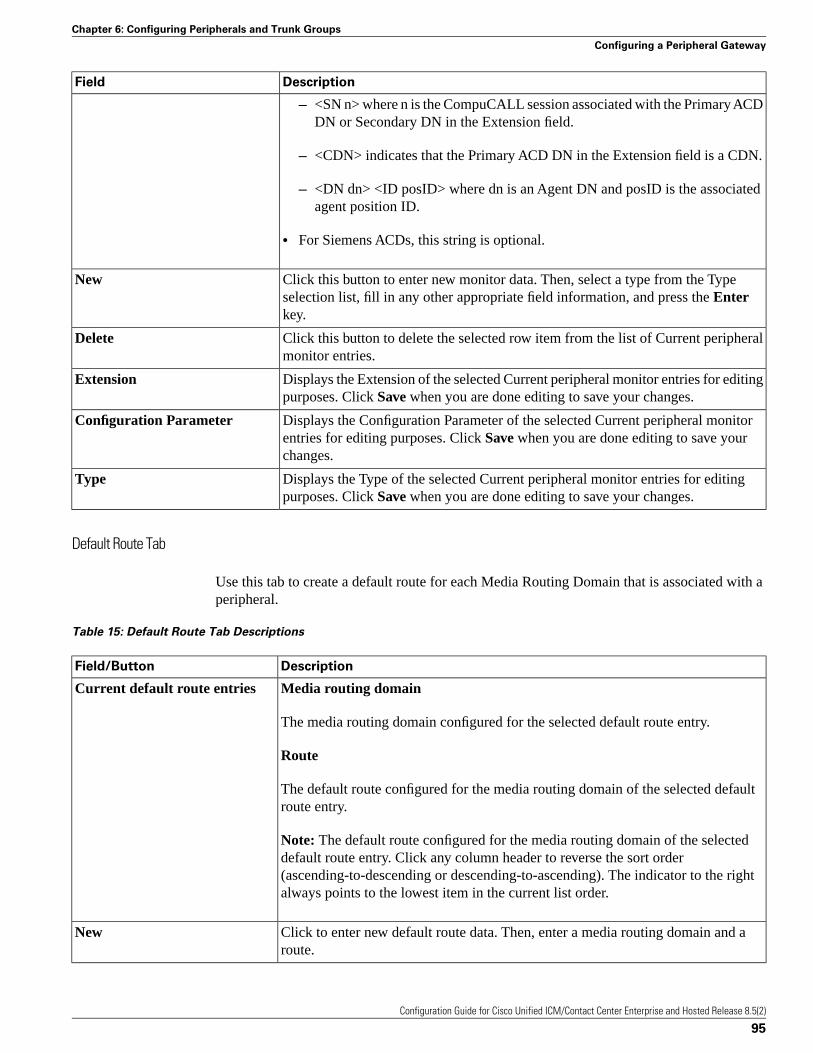
DescriptionField
– <SN n> where n is the CompuCALL session associated with the Primary ACDDN or Secondary DN in the Extension field.
– <CDN> indicates that the Primary ACD DN in the Extension field is a CDN.
– <DN dn> <ID posID> where dn is an Agent DN and posID is the associatedagent position ID.
• For Siemens ACDs, this string is optional.
Click this button to enter new monitor data. Then, select a type from the Typeselection list, fill in any other appropriate field information, and press the Enterkey.
New
Click this button to delete the selected row item from the list of Current peripheralmonitor entries.
Delete
Displays the Extension of the selected Current peripheral monitor entries for editingpurposes. Click Save when you are done editing to save your changes.
Extension
Displays the Configuration Parameter of the selected Current peripheral monitorentries for editing purposes. Click Save when you are done editing to save yourchanges.
Configuration Parameter
Displays the Type of the selected Current peripheral monitor entries for editingpurposes. Click Save when you are done editing to save your changes.
Type
Default Route Tab
Use this tab to create a default route for each Media Routing Domain that is associated with aperipheral.
Table 15: Default Route Tab Descriptions
DescriptionField/Button
Media routing domainCurrent default route entries
The media routing domain configured for the selected default route entry.
Route
The default route configured for the media routing domain of the selected defaultroute entry.
Note: The default route configured for the media routing domain of the selecteddefault route entry. Click any column header to reverse the sort order(ascending-to-descending or descending-to-ascending). The indicator to the rightalways points to the lowest item in the current list order.
Click to enter new default route data. Then, enter a media routing domain and aroute.
New
Configuration Guide for Cisco Unified ICM/Contact Center Enterprise and Hosted Release 8.5(2)
95
Chapter 6: Configuring Peripherals and Trunk Groups
Configuring a Peripheral Gateway
DescriptionField/Button
Click to delete the selected row item from the list of current default route entries.Delete
Enter the media routing domain when creating a new default route entry.Media routing domain (required)
Enter the route when creating a new default route entry.Route
Agent Distribution Tab
Use the Agent Distribution tab to list and view the agent distributions currently defined in theUnified ICM database and (if you have maintenance access) to define new agent distributions,and to edit, or delete existing ones. This data is stored in the database Agent Distribution table.
Note: The PG Explorer (and the assigning of agent distribution) is not available on a limitedAdministration and Data Server.
Table 16: Agent Distribution Tab Field Descriptions
DescriptionField
Specifies whether agent reporting is enabled for the peripheral. Select this option ifyou want the peripheral to report agent-level statistics to the system software.
Enable agent reporting
Note:
• Agent Reporting implies Auto Configuration. Agent Reporting withoutauto-configuration is NOT supported. Unified ICM does not support AgentReporting on manually configured agents with auto-configuration off.
• If the client of the peripheral is CallManager/SoftACD, then you must select anagent desk setting in the PG Explorer Peripheral tab before you can enable agentreporting. The client type of the peripheral is indicated in the PG ExplorerPeripheral tab.
Specifies whether agent event detail reporting is enabled for the peripheral. Thischeckbox is enabled only if the Enable agent reporting checkbox is selected.Making this selection adds reason codes to agent reporting.
Agent event detail
Note: This checkbox is enabled by default if you are adding a Unified CM PG.
Lists the agent distributors (Administration Clients or Administration & Data Servers)available for distributing agent report data for the selected peripheral.
Agent distribution entries
Site name
One or more names of agent distribution sites associated with the selected peripheral.
Agent real time data
N indicates the agent real time data is not enabled. Y indicates the agent real timedata is enabled.
Agent historical data
Configuration Guide for Cisco Unified ICM/Contact Center Enterprise and Hosted Release 8.5(2)
96
Chapter 6: Configuring Peripherals and Trunk Groups
Configuring a Peripheral Gateway
DescriptionField
N indicates the agent historical data is not enabled. Y indicates the agent historicaldata is enabled.
Administration & Data Server site nameCurrently selected site
The name of the currently selected site in the agent distribution entries list.
Agent real time data
If checked, enables the flow of agent real time data from the peripheral to theAdministration & Data Server. Unchecked, disables the flow of agent real time data.
Agent historical data
If checked, enables the flow of agent historical data from the peripheral to theAdministration & Data Server. Unchecked, disables the flow of agent historicaldata.
Click to add a new Administration & Data Server site. This places *NEW* in theAdministration & Data Server site name input box and in the Agent Distribution
New
Entries list. Replace *NEW* in the Administration & Data Server site name inputbox with the name you want. Then click the checkbox if you want to enable it, andclick Save.
To delete an Administration & Data Server site, select that site name in the AgentDistribution Entries list and click this button. Then click Save.
Delete
Note: For information about how to use the AgentCfg command line utility to import agentdata, see “Importing Agent Configuration Data from the Peripheral (page 133)” in the“Configuring Skill Targets” section.
Defining Peripheral Gateways and Peripherals
Use the PG Explorer to define a PG and its associated peripherals.
How to Define a PG
Note: The “Configuring the System Peripheral Gateways (page 98)” section contains an exampleof how to define a PG on a child deployment, which is documented in the Cisco Contact CenterGateway Deployment Guide for Cisco Unified ICME/CCE/CCX.
To define a PG, perform the following:
Step 1 From the Configuration Manager menu, select Tools > Explorer Tools > PG Explorer. ThePG Explorer window appears.
Step 2 In the Select filter data box, click Retrieve. This enables the Add PG button.
Step 3 Click Add PG. A new PG appears in the tree list box with a To Be Inserted icon
Configuration Guide for Cisco Unified ICM/Contact Center Enterprise and Hosted Release 8.5(2)
97
Chapter 6: Configuring Peripherals and Trunk Groups
Configuring a Peripheral Gateway
Figure 29: PG to be inserted icon
next to it. Tabbed fields also appear on the right for the new PG configuration information.
Step 4 Fill in the tabbed fields. (For field descriptions, see the “PG Explorer Tab Descriptions (page85)” section.
Step 5 If desired, set security settings on the records. (See the “How to View or Apply Security Settings(page 29)” section.)
Step 6 Click Save to save the newly defined PG in the database.
How to Define a Peripheral
Follow the steps for defining a peripheral:
Step 1 Follow the steps for viewing a PG. (See the “How to View PG Records (page 83)” section.)
The configuration information for the selected PG appears in the fields on the right. For fielddescriptions, see the “PG Explorer Tab Descriptions (page 85)” section.
Step 2 In the tree list box, select the PG to which you want to add a peripheral. This enables the AddPeripheral button.
Step 3 Click Add Peripheral. A peripheral is added to the selected PG in the tree list box. Also a newset of tabbed fields appear on the right for configuration information for the new PG.
Step 4 Enter the needed peripheral configuration information in the fields on the right. (For fielddescriptions, see “Table Peripheral Tab Descriptions (page 89).”)
Step 5 If desired, set security settings on the records. (See the “How to View or Apply Security Settings(page 63)” section.)
Step 6 Click Save.
After you have defined a peripheral, you can define the trunks, agents, groups, and servicesassociated with that peripheral.
Configuring the System Peripheral Gateways
On the Administration & Data Server, run the Configuration Manager to add the SystemPeripheral Gateways.
How to Configure the System PGs
Use the Configuration Manager tools to add and configure the System PGs.
Configuration Guide for Cisco Unified ICM/Contact Center Enterprise and Hosted Release 8.5(2)
98
Chapter 6: Configuring Peripherals and Trunk Groups
Configuring a Peripheral Gateway

Step 1 Select Start > All Programs > Cisco Unified CCE Tools > Administration Tools >Configuration Manager.
Step 2 Start the PG Explorer Tool, then in the Main window click Retrieve.
Step 3 Click Add PG.
This creates both the Peripheral Gateway and the Peripheral.
a. Enter IPCC for the Name.
b. Select IPCC System for the Client Type.
c. If no desk settings are set, set them now. Click OK.
The Agent Desk Settings List Tool appears.
d. Click Add.
The Attribute tab appears.
e. Enter the Name default.
f. Leave all other settings at their defaults and click Save.
g. Close the Desk Settings List Tool.
Step 4 Go back to the PG Explorer Tool.
a. Select IPCC-1 as the Peripheral.
b. On the Peripheral tab, set the Default Desk Settings to default.
c. On the Agent Distribution tab, click New.
d. Set the Administration & Data Server site name to BELO-5C-Site 1 and leave all othersettings at their defaults.
e. On the Routing Client tab, enter the Name IPCC_RC and leave all other settings at theirdefaults.
f. Click Save.
The Logical Controller ID (5000) and the Physical Controller ID (5000) are now indicated onthe Logical Controller tab.
g. Reboot the System Peripheral Gateway computers (BELO-5A and BELO-5B).
The Central Controller setup and configuration is now complete. The Peripheral Gateways cannow be installed and configured to communicate with the Central Controller.
Configuration Guide for Cisco Unified ICM/Contact Center Enterprise and Hosted Release 8.5(2)
99
Chapter 6: Configuring Peripherals and Trunk Groups
Configuring a Peripheral Gateway
How to Add the Instance
This task is performed on the Child System Peripheral Gateway computers BELO-5A (PG1A)and BELO-5B (PG1B).
After the reboot, use the Web Setup Tool to add the Instance.
Step 1 Enter http://BELO-5B/setup (or BELO-5A, as applicable) and log in to the Web Setup Toolto add the Instance. The main Web Setup Tool window appears.
Step 2 Click Instance Management, then click Add.
The Add Instance dialog appears.
Step 3 Select BELO (the Facility), then bh03 (the Instance to add).
Step 4 Click Save.
Step 5 Click Log Out.
Modifying a PG or Peripheral
Use the PG Explorer to modify a PG or a peripheral.
How to Modify a Peripheral Gateway and Peripheral Records
Follow the steps to modify a PG and peripheral records:
Step 1 Follow the steps for viewing a PG. (See the “How to View PG Records (page 83)” section.)
The configuration information for the selected PG is displayed in the fields on the right.
Step 2 Edit the configuration information. (For field descriptions, see the “PG Explorer Tab Descriptions(page 85)” section.)
Note: You cannot modify fields that are greyed out.
Table 17: Rules for Changing the Client Type of a PG
Then it can beIf the PG Client Type is
Changed to PG_Generic.Non PG_Generic (ACD orVRU)
Changed to VRU or a specific ACD type if and only if allperipherals configured for that PG are of the same type.
PG_Generic
Changed to Rockwell Spectrum.Rockwell r1.3 ACD
Configuration Guide for Cisco Unified ICM/Contact Center Enterprise and Hosted Release 8.5(2)
100
Chapter 6: Configuring Peripherals and Trunk Groups
Configuring a Peripheral Gateway
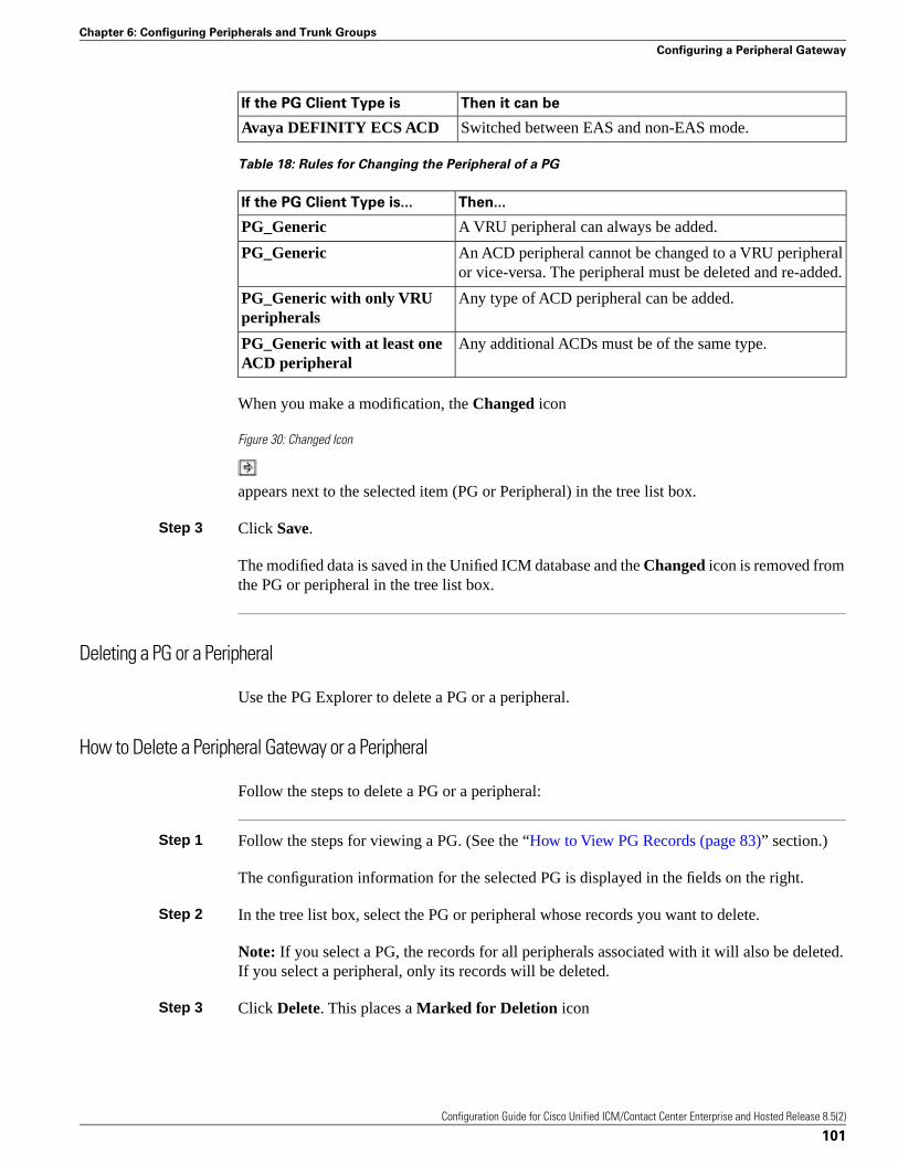
Then it can beIf the PG Client Type is
Switched between EAS and non-EAS mode.Avaya DEFINITY ECS ACD
Table 18: Rules for Changing the Peripheral of a PG
Then...If the PG Client Type is...
A VRU peripheral can always be added.PG_Generic
An ACD peripheral cannot be changed to a VRU peripheralor vice-versa. The peripheral must be deleted and re-added.
PG_Generic
Any type of ACD peripheral can be added.PG_Generic with only VRUperipherals
Any additional ACDs must be of the same type.PG_Generic with at least oneACD peripheral
When you make a modification, the Changed icon
Figure 30: Changed Icon
appears next to the selected item (PG or Peripheral) in the tree list box.
Step 3 Click Save.
The modified data is saved in the Unified ICM database and the Changed icon is removed fromthe PG or peripheral in the tree list box.
Deleting a PG or a Peripheral
Use the PG Explorer to delete a PG or a peripheral.
How to Delete a Peripheral Gateway or a Peripheral
Follow the steps to delete a PG or a peripheral:
Step 1 Follow the steps for viewing a PG. (See the “How to View PG Records (page 83)” section.)
The configuration information for the selected PG is displayed in the fields on the right.
Step 2 In the tree list box, select the PG or peripheral whose records you want to delete.
Note: If you select a PG, the records for all peripherals associated with it will also be deleted.If you select a peripheral, only its records will be deleted.
Step 3 Click Delete. This places a Marked for Deletion icon
Configuration Guide for Cisco Unified ICM/Contact Center Enterprise and Hosted Release 8.5(2)
101
Chapter 6: Configuring Peripherals and Trunk Groups
Configuring a Peripheral Gateway
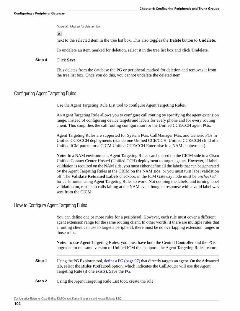
Figure 31: Marked for deletion Icon
next to the selected item in the tree list box. This also toggles the Delete button to Undelete.
To undelete an item marked for deletion, select it in the tree list box and click Undelete.
Step 4 Click Save.
This deletes from the database the PG or peripheral marked for deletion and removes it fromthe tree list box. Once you do this, you cannot undelete the deleted item.
Configuring Agent Targeting Rules
Use the Agent Targeting Rule List tool to configure Agent Targeting Rules.
An Agent Targeting Rule allows you to configure call routing by specifying the agent extensionrange, instead of configuring device targets and labels for every phone and for every routingclient. This simplifies the call routing configuration for the Unified CCE/CCH agent PGs.
Agent Targeting Rules are supported for System PGs, CallManager PGs, and Generic PGs inUnified CCE/CCH deployments (standalone Unified CCE/CCH, Unified CCE/CCH child of aUnified ICM parent, or a CICM Unified CCE/CCH Enterprise in a NAM deployment).
Note: In a NAM environment, Agent Targeting Rules can be used on the CICM side in a CiscoUnified Contact Center Hosted (Unified CCH) deployment to target agents. However, if labelvalidation is required on the NAM side, you must either define all the labels that can be generatedby the Agent Targeting Rules at the CICM on the NAM side, or you must turn label validationoff. The Validate Returned Labels checkbox in the ICM Gateway node must be uncheckedfor calls routed using Agent Targeting Rules to work. Not defining the labels, and turning labelvalidation on, results in calls failing at the NAM even though a response with a valid label wassent from the CICM.
How to Configure Agent Targeting Rules
You can define one or more rules for a peripheral. However, each rule must cover a differentagent extension range for the same routing client. In other words, if there are multiple rules thata routing client can use to target a peripheral, there must be no overlapping extension ranges inthose rules.
Note: To use Agent Targeting Rules, you must have both the Central Controller and the PGsupgraded to the same version of Unified ICM that supports the Agent Targeting Rules feature.
Step 1 Using the PG Explorer tool, define a PG (page 97) that directly targets an agent. On the Advancedtab, select the Rules Preferred option, which indicates the CallRouter will use the AgentTargeting Rule (if one exists). Save the PG.
Step 2 Using the Agent Targeting Rule List tool, create the rule:
Configuration Guide for Cisco Unified ICM/Contact Center Enterprise and Hosted Release 8.5(2)
102
Chapter 6: Configuring Peripherals and Trunk Groups
Configuring a Peripheral Gateway

a. Add a name for the rule in the Name field.
b. Select the PG you just defined in the Peripheral field.
c. Select the Rule type:
• Agent Extension: Enter the agent extension prefix. This option directly targets the agent .The agent is identified by an ID, which will display in the PreCall and Connect messages.(The agent’s extension is included as the label.)
• Substitute Agent Extension: Enter the agent extension length. When using this type, thelabel returned will be the combined Agent Extension prefix and the actual agent extension.For example, if the call from Unified CVP goes through the target agent on a CallManagerPG, then use this option.
• Translation Route: A translation route is used to move the call. This option allows pre-routingof calls directly to an agent without requiring DID to all agents. Translation routes requirethe generation of a second label, used to target the agent from the peripheral’s local routingclient. For example, select a translation route associated with the peripheral and define theextension range.
d. Select the routing client in the Routing client group box by clicking Add (defines wherethe call comes from).
e. Add the phone extension range in the Extension Ranges group box by clicking Add.
f. Click Save.
When the CallRouter routes a call, it will check if there is a rule for that routing client. TheCallRouter decides which rule to use based on routing client, PG, and extension range. Whenthe CallRouter finds a rule, it uses the rule type to decide how to construct a label to send to therouting client.
Note: When configuring an Agent Targeting Rule for a Translation Route, if you are usingAgent Targeting Rule Type 3 (Translation Route), you must also configure the TranslationRoute DNIS as dialed numbers associated with the target agent’s peripheral routing client inUnified ICM. The dialed numbers must be mapped to the route points that are configured inUnified CM and associated with the JTAPI user. This is necessary to complete the TranslationRoute Rule.
Configuring Trunk Groups and Trunks
Every peripheral has one or more associated trunk groups, with each trunk group containingone or more physical trunks. Trunk groups map to trunk sets defined by the peripheral.
A peripheral dispatches a call to the appropriate skill target based on the trunk group on whichthe call arrives and the DNIS value that accompanies it. The peripheral treats all trunks with aparticular trunk group the same, but it might treat trunks within another trunk group differently.
Configuration Guide for Cisco Unified ICM/Contact Center Enterprise and Hosted Release 8.5(2)
103
Chapter 6: Configuring Peripherals and Trunk Groups
Configuring Trunk Groups and Trunks
Note: The DMS-100 does not have trunk groups, but within the system software you mustdefine one network trunk group and one trunk group for each DMS-100.
When setting up trunk groups and trunks, you must specify:
• Each trunk group that can receive calls
• How many trunks are in each trunk group, or configuration information for each trunk in thegroup
This section describes how to configure the trunk groups and trunks that will be used by routingclients and peripherals.
Network Trunk Groups, Trunk Groups, and Trunks
Routing clients deliver calls to trunk groups at the peripheral. However, a routing client mightgroup the trunks differently from the way the peripheral groups them. The groups as seen bythe routing client are called network trunk groups.
A network trunk group:
• Is a collection of peripheral trunk groups.
• Can map directly to a single trunk group at the peripheral or to multiple trunk groups.
• Can also map to trunk groups at different peripherals, provided that all the peripherals areassociated with the same Peripheral Gateway. (Only valid for VRU peripherals.)
How to View a Network Trunk Group, Its Trunk Groups, and Its Trunks
Follow the steps to view a network trunk group, its trunk groups, and its trunks:
Step 1 From the Configuration Manager menu, select Tools Explorer Tools Network Trunk GroupExplorer. The Network Trunk Group Explorer window appears.
Configuration Guide for Cisco Unified ICM/Contact Center Enterprise and Hosted Release 8.5(2)
104
Chapter 6: Configuring Peripherals and Trunk Groups
Configuring Trunk Groups and Trunks
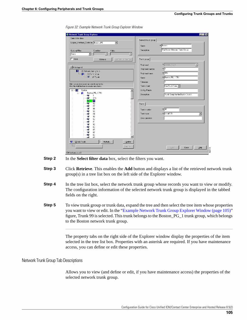
Figure 32: Example Network Trunk Group Explorer Window
Step 2 In the Select filter data box, select the filters you want.
Step 3 Click Retrieve. This enables the Add button and displays a list of the retrieved network trunkgroup(s) in a tree list box on the left side of the Explorer window.
Step 4 In the tree list box, select the network trunk group whose records you want to view or modify.The configuration information of the selected network trunk group is displayed in the tabbedfields on the right.
Step 5 To view trunk group or trunk data, expand the tree and then select the tree item whose propertiesyou want to view or edit. In the “Example Network Trunk Group Explorer Window (page 105)”figure, Trunk 99 is selected. This trunk belongs to the Boston_PG_1 trunk group, which belongsto the Boston network trunk group.
The property tabs on the right side of the Explorer window display the properties of the itemselected in the tree list box. Properties with an asterisk are required. If you have maintenanceaccess, you can define or edit these properties.
Network Trunk Group Tab Descriptions
Allows you to view (and define or edit, if you have maintenance access) the properties of theselected network trunk group.
Configuration Guide for Cisco Unified ICM/Contact Center Enterprise and Hosted Release 8.5(2)
105
Chapter 6: Configuring Peripherals and Trunk Groups
Configuring Trunk Groups and Trunks
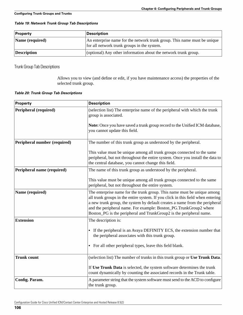
Table 19: Network Trunk Group Tab Descriptions
DescriptionProperty
An enterprise name for the network trunk group. This name must be uniquefor all network trunk groups in the system.
Name (required)
(optional) Any other information about the network trunk group.Description
Trunk Group Tab Descriptions
Allows you to view (and define or edit, if you have maintenance access) the properties of theselected trunk group.
Table 20: Trunk Group Tab Descriptions
DescriptionProperty
(selection list) The enterprise name of the peripheral with which the trunkgroup is associated.
Peripheral (required)
Note: Once you have saved a trunk group record to the Unified ICM database,you cannot update this field.
The number of this trunk group as understood by the peripheral.Peripheral number (required)
This value must be unique among all trunk groups connected to the sameperipheral, but not throughout the entire system. Once you install the data tothe central database, you cannot change this field.
The name of this trunk group as understood by the peripheral.Peripheral name (required)
This value must be unique among all trunk groups connected to the sameperipheral, but not throughout the entire system.
The enterprise name for the trunk group. This name must be unique amongall trunk groups in the entire system. If you click in this field when entering
Name (required)
a new trunk group, the system by default creates a name from the peripheraland the peripheral name. For example: Boston_PG.TrunkGroup2 whereBoston_PG is the peripheral and TrunkGroup2 is the peripheral name.
The description is:Extension
• If the peripheral is an Avaya DEFINITY ECS, the extension number thatthe peripheral associates with this trunk group.
• For all other peripheral types, leave this field blank.
(selection list) The number of trunks in this trunk group or Use Trunk Data.Trunk count
If Use Trunk Data is selected, the system software determines the trunkcount dynamically by counting the associated records in the Trunk table.
A parameter string that the system software must send to the ACD to configurethe trunk group.
Config. Param.
Configuration Guide for Cisco Unified ICM/Contact Center Enterprise and Hosted Release 8.5(2)
106
Chapter 6: Configuring Peripherals and Trunk Groups
Configuring Trunk Groups and Trunks
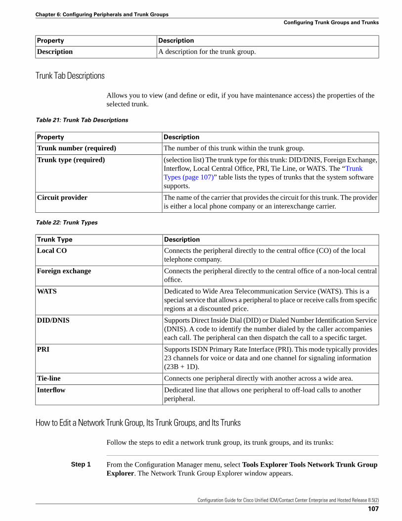
DescriptionProperty
A description for the trunk group.Description
Trunk Tab Descriptions
Allows you to view (and define or edit, if you have maintenance access) the properties of theselected trunk.
Table 21: Trunk Tab Descriptions
DescriptionProperty
The number of this trunk within the trunk group.Trunk number (required)
(selection list) The trunk type for this trunk: DID/DNIS, Foreign Exchange,Interflow, Local Central Office, PRI, Tie Line, or WATS. The “Trunk
Trunk type (required)
Types (page 107)” table lists the types of trunks that the system softwaresupports.
The name of the carrier that provides the circuit for this trunk. The provideris either a local phone company or an interexchange carrier.
Circuit provider
Table 22: Trunk Types
DescriptionTrunk Type
Connects the peripheral directly to the central office (CO) of the localtelephone company.
Local CO
Connects the peripheral directly to the central office of a non-local centraloffice.
Foreign exchange
Dedicated to Wide Area Telecommunication Service (WATS). This is aspecial service that allows a peripheral to place or receive calls from specificregions at a discounted price.
WATS
Supports Direct Inside Dial (DID) or Dialed Number Identification Service(DNIS). A code to identify the number dialed by the caller accompanieseach call. The peripheral can then dispatch the call to a specific target.
DID/DNIS
Supports ISDN Primary Rate Interface (PRI). This mode typically provides23 channels for voice or data and one channel for signaling information(23B + 1D).
PRI
Connects one peripheral directly with another across a wide area.Tie-line
Dedicated line that allows one peripheral to off-load calls to anotherperipheral.
Interflow
How to Edit a Network Trunk Group, Its Trunk Groups, and Its Trunks
Follow the steps to edit a network trunk group, its trunk groups, and its trunks:
Step 1 From the Configuration Manager menu, select Tools Explorer Tools Network Trunk GroupExplorer. The Network Trunk Group Explorer window appears.
Configuration Guide for Cisco Unified ICM/Contact Center Enterprise and Hosted Release 8.5(2)
107
Chapter 6: Configuring Peripherals and Trunk Groups
Configuring Trunk Groups and Trunks
Step 2 In the Select filter data box, select the filters you want.
Step 3 Click Retrieve. This displays a list of the retrieved network trunk group(s) in a tree list box onthe left side of the Explorer window.
Step 4 In the tree list box, select the item you want to edit. Expand the tree if necessary. This displaysthe property tab for the selected item on the right side of the window.
Step 5 Edit the appropriate properties. For property descriptions, see the “Network Trunk Group TabDescriptions (page 104)” section.
Step 6 Click Save.
How to Define a Network Trunk Group, Its Trunk Groups, and Its Trunks
Follow the steps to define a network trunk group, its trunk groups, and its trunks:
Step 1 From the Configuration Manager menu, select Tools Explorer Tools Network Trunk Group.The Network Trunk Group Explorer window appears.
Step 2 In the Select filter data box, select the filters you want.
Step 3 Click Retrieve. This displays a list of the retrieved trunk groups and enables the add functionality.
Step 4 This step depends on what you want to do:
a. To add a new network trunk group, click Add Network Trunk Group.
b. To add a new trunk group, select the network trunk group to which you want to add agroup, and click Add Network Trunk Group.
c. To add a new trunk, select the trunk group to which you want to add a trunk, and clickAdd Trunk.
Step 5 Enter the appropriate values in the tabbed property fields on the right side of the window. Forproperty descriptions, see the “Network Trunk Group Tab Descriptions (page 104)” section.
Step 6 Click Save.
How to Delete a Network Trunk Group, Its Trunk Groups, and Its Trunks
Follow the steps to delete a network trunk group, its trunk groups, and its trunks:
Step 1 From the Configuration Manager menu, select Tools Explorer Tools Network Trunk GroupExplorer. The Network Trunk Group Explorer window appears.
Step 2 In the Select filter data box, select the filters you want.
Configuration Guide for Cisco Unified ICM/Contact Center Enterprise and Hosted Release 8.5(2)
108
Chapter 6: Configuring Peripherals and Trunk Groups
Configuring Trunk Groups and Trunks
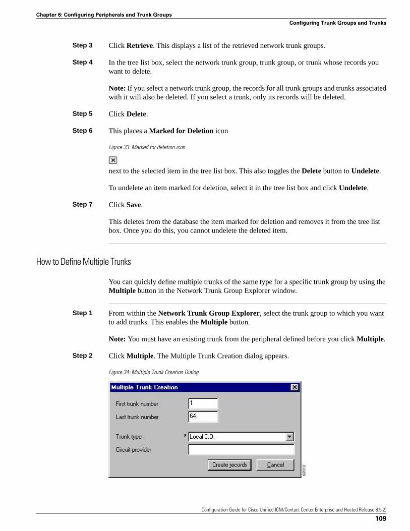
Step 3 Click Retrieve. This displays a list of the retrieved network trunk groups.
Step 4 In the tree list box, select the network trunk group, trunk group, or trunk whose records youwant to delete.
Note: If you select a network trunk group, the records for all trunk groups and trunks associatedwith it will also be deleted. If you select a trunk, only its records will be deleted.
Step 5 Click Delete.
Step 6 This places a Marked for Deletion icon
Figure 33: Marked for deletion icon
next to the selected item in the tree list box. This also toggles the Delete button to Undelete.
To undelete an item marked for deletion, select it in the tree list box and click Undelete.
Step 7 Click Save.
This deletes from the database the item marked for deletion and removes it from the tree listbox. Once you do this, you cannot undelete the deleted item.
How to Define Multiple Trunks
You can quickly define multiple trunks of the same type for a specific trunk group by using theMultiple button in the Network Trunk Group Explorer window.
Step 1 From within the Network Trunk Group Explorer, select the trunk group to which you wantto add trunks. This enables the Multiple button.
Note: You must have an existing trunk from the peripheral defined before you click Multiple.
Step 2 Click Multiple. The Multiple Trunk Creation dialog appears.
Figure 34: Multiple Trunk Creation Dialog
Configuration Guide for Cisco Unified ICM/Contact Center Enterprise and Hosted Release 8.5(2)
109
Chapter 6: Configuring Peripherals and Trunk Groups
Configuring Trunk Groups and Trunks
Step 3 Set the First trunk number and the Last trunk number fields so that you define the range oftrunks you want.
Step 4 In the Trunk type field, select the trunk type. For a description of trunk types, see the “TrunkTypes (page 107)” table.
Step 5 (optional) In the Circuit provider field, enter the name of the carrier that provides the circuit forthis trunk.
Step 6 Click Create records. The tree list box will display a list of the numbered trunks beneath theselected trunk group and the Trunk tab on the right side of the window will display the propertiesof the trunk at the end of the series of numbers.
Step 7 In the Network Trunk Group Explorer window, click Save.
Note: If a trunk number in the range you specified has already been used, that trunk number isselected in the tree list box and a message is displayed. Before you can save the data, you mustedit the trunk number.
Configuration Guide for Cisco Unified ICM/Contact Center Enterprise and Hosted Release 8.5(2)
110
Chapter 6: Configuring Peripherals and Trunk Groups
Configuring Trunk Groups and Trunks
Configuring Skill TargetsThis chapter describes how to set up the entities that the system software selects to handle callsat a peripheral.
It includes:
• An introduction to the skill targets subsystem
• Instructions on how to view, define, delete, or modify:
– Services
– Skill Groups
– Agents
– Persons
– Agent reporting
– Enterprise services
– Enterprise skill groups
This chapter also includes instructions for using the agentcfg.exe utility that allows you to updateyour Unified ICM database with agent information from a Unified ICM peripheral.
This chapter contains the following topics:
• The Skill Targets Subsystem, page 112• Services, page 112• Skill Groups, page 118• Modifying the Skill Groups Per Agent Limit, page 128• Persons, page 130
Configuration Guide for Cisco Unified ICM/Contact Center Enterprise and Hosted Release 8.5(2)
111
Chapter 7
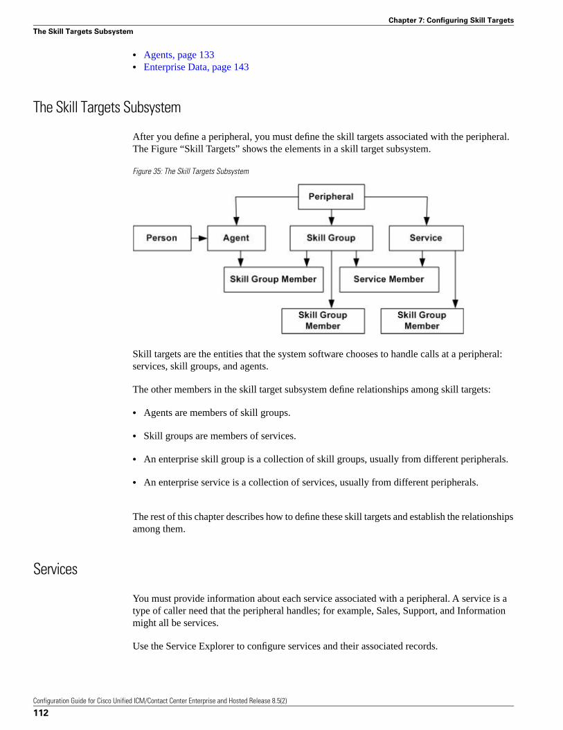
• Agents, page 133• Enterprise Data, page 143
The Skill Targets Subsystem
After you define a peripheral, you must define the skill targets associated with the peripheral.The Figure “Skill Targets” shows the elements in a skill target subsystem.
Figure 35: The Skill Targets Subsystem
Skill targets are the entities that the system software chooses to handle calls at a peripheral:services, skill groups, and agents.
The other members in the skill target subsystem define relationships among skill targets:
• Agents are members of skill groups.
• Skill groups are members of services.
• An enterprise skill group is a collection of skill groups, usually from different peripherals.
• An enterprise service is a collection of services, usually from different peripherals.
The rest of this chapter describes how to define these skill targets and establish the relationshipsamong them.
Services
You must provide information about each service associated with a peripheral. A service is atype of caller need that the peripheral handles; for example, Sales, Support, and Informationmight all be services.
Use the Service Explorer to configure services and their associated records.
Configuration Guide for Cisco Unified ICM/Contact Center Enterprise and Hosted Release 8.5(2)
112
Chapter 7: Configuring Skill Targets
The Skill Targets Subsystem
Service Explorer
The following sections show you how to use the Service Explorer to view and configure aservice and its associated routes, peripheral targets, and labels.
How to View a Service
To view a service, follow these steps:
Step 1 In the Configuration Manager menu, select Tools > Explorer Tools > Service Explorer. TheService Explorer window appears.
Step 2 In the Select filter data box, select the peripheral associated with the service you want to view.You can choose the name from the drop-down list.
Note: Once you have saved a service record to the Unified ICM database, you cannot changethe peripheral to which it is associated.
Step 3 Select any other filters you want. None in the Optional filter box means all services associatedwith the selected peripheral will be displayed.
Step 4 Click Retrieve. This lists in the tree list box the name(s) of the retrieved service(s).
Note: A tree object is unassigned if it was made by another configuration tool and was notassigned (mapped) to a parent object; for example, a label might not have been assigned to aperipheral target or a route might not have been assigned to a service, and so on.
Step 5 In the tree list box, select a service to display its configuration information on the right side ofthe window.
Step 6 If the service has a route associated with it, click its icon in the tree list box to display itsconfiguration information. Do the same for a peripheral target associated with the route and alabel associated with the peripheral target.
Service Explorer Tab Descriptions
The tables in the following sections describe the fields in the Service Explorer records.
Service Tab
This tab allows you to view (and define or edit, if you have maintenance access) the propertiesof the selected service.
A service is the type of caller need that a peripheral handles; for example, Sales, Support, andInformation.
Configuration Guide for Cisco Unified ICM/Contact Center Enterprise and Hosted Release 8.5(2)
113
Chapter 7: Configuring Skill Targets
Services
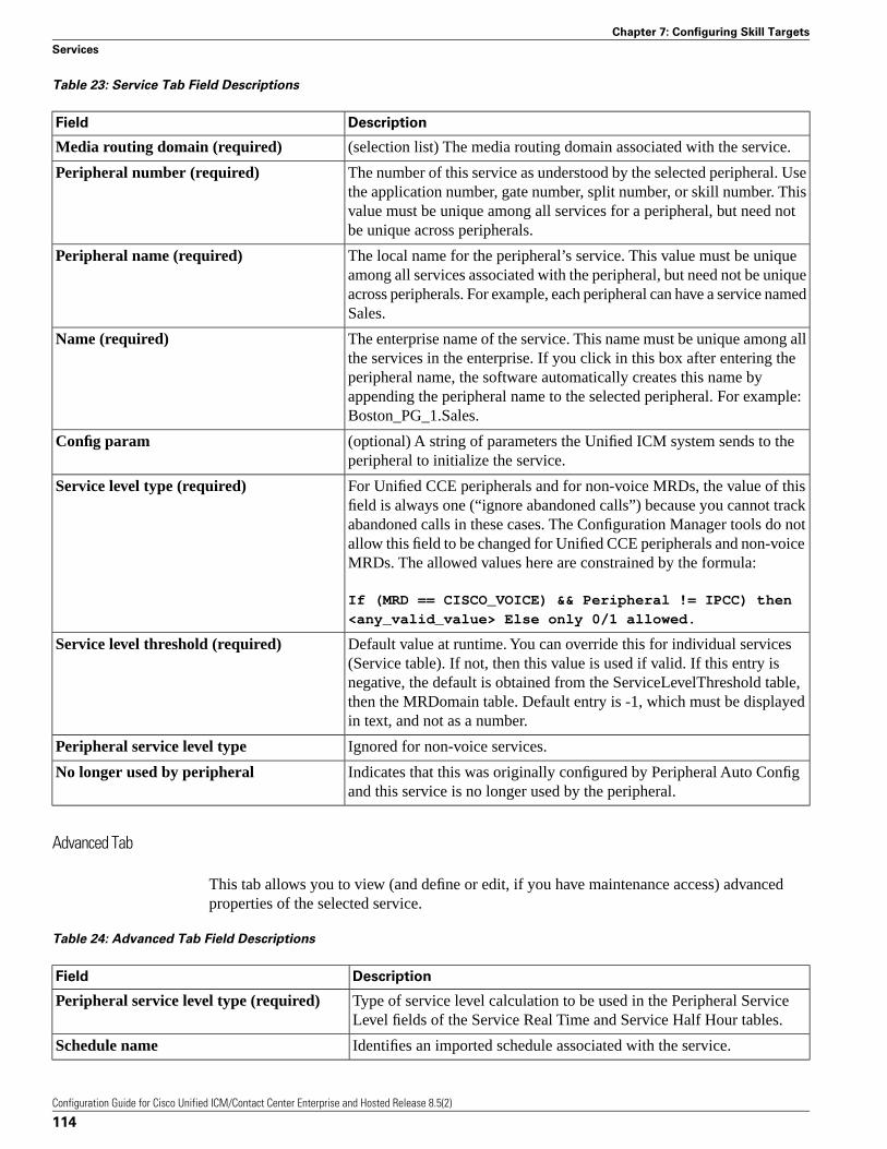
Table 23: Service Tab Field Descriptions
DescriptionField
(selection list) The media routing domain associated with the service.Media routing domain (required)
The number of this service as understood by the selected peripheral. Usethe application number, gate number, split number, or skill number. This
Peripheral number (required)
value must be unique among all services for a peripheral, but need notbe unique across peripherals.
The local name for the peripheral’s service. This value must be uniqueamong all services associated with the peripheral, but need not be unique
Peripheral name (required)
across peripherals. For example, each peripheral can have a service namedSales.
The enterprise name of the service. This name must be unique among allthe services in the enterprise. If you click in this box after entering the
Name (required)
peripheral name, the software automatically creates this name byappending the peripheral name to the selected peripheral. For example:Boston_PG_1.Sales.
(optional) A string of parameters the Unified ICM system sends to theperipheral to initialize the service.
Config param
For Unified CCE peripherals and for non-voice MRDs, the value of thisfield is always one (“ignore abandoned calls”) because you cannot track
Service level type (required)
abandoned calls in these cases. The Configuration Manager tools do notallow this field to be changed for Unified CCE peripherals and non-voiceMRDs. The allowed values here are constrained by the formula:
If (MRD == CISCO_VOICE) && Peripheral != IPCC) then
<any_valid_value> Else only 0/1 allowed.
Default value at runtime. You can override this for individual services(Service table). If not, then this value is used if valid. If this entry is
Service level threshold (required)
negative, the default is obtained from the ServiceLevelThreshold table,then the MRDomain table. Default entry is -1, which must be displayedin text, and not as a number.
Ignored for non-voice services.Peripheral service level type
Indicates that this was originally configured by Peripheral Auto Configand this service is no longer used by the peripheral.
No longer used by peripheral
Advanced Tab
This tab allows you to view (and define or edit, if you have maintenance access) advancedproperties of the selected service.
Table 24: Advanced Tab Field Descriptions
DescriptionField
Type of service level calculation to be used in the Peripheral ServiceLevel fields of the Service Real Time and Service Half Hour tables.
Peripheral service level type (required)
Identifies an imported schedule associated with the service.Schedule name
Configuration Guide for Cisco Unified ICM/Contact Center Enterprise and Hosted Release 8.5(2)
114
Chapter 7: Configuring Skill Targets
Services
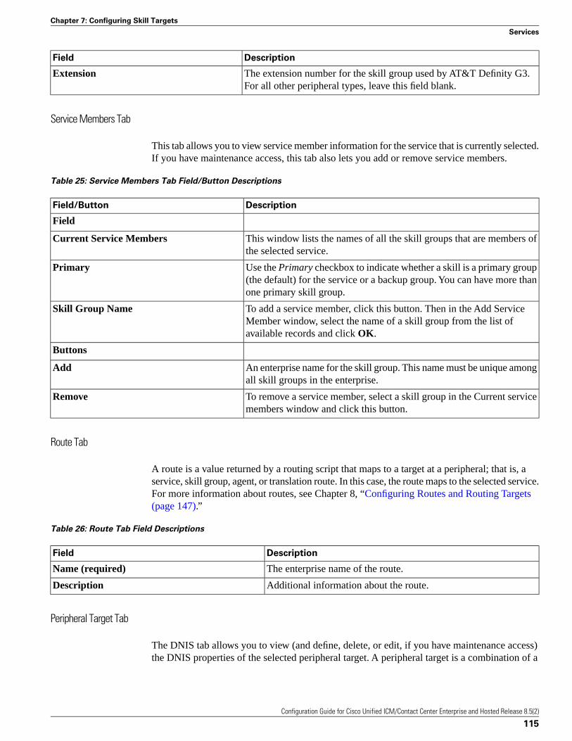
DescriptionField
The extension number for the skill group used by AT&T Definity G3.For all other peripheral types, leave this field blank.
Extension
Service Members Tab
This tab allows you to view service member information for the service that is currently selected.If you have maintenance access, this tab also lets you add or remove service members.
Table 25: Service Members Tab Field/Button Descriptions
DescriptionField/Button
Field
This window lists the names of all the skill groups that are members ofthe selected service.
Current Service Members
Use the Primary checkbox to indicate whether a skill is a primary group(the default) for the service or a backup group. You can have more thanone primary skill group.
Primary
To add a service member, click this button. Then in the Add ServiceMember window, select the name of a skill group from the list ofavailable records and click OK.
Skill Group Name
Buttons
An enterprise name for the skill group. This name must be unique amongall skill groups in the enterprise.
Add
To remove a service member, select a skill group in the Current servicemembers window and click this button.
Remove
Route Tab
A route is a value returned by a routing script that maps to a target at a peripheral; that is, aservice, skill group, agent, or translation route. In this case, the route maps to the selected service.For more information about routes, see Chapter 8, “Configuring Routes and Routing Targets(page 147).”
Table 26: Route Tab Field Descriptions
DescriptionField
The enterprise name of the route.Name (required)
Additional information about the route.Description
Peripheral Target Tab
The DNIS tab allows you to view (and define, delete, or edit, if you have maintenance access)the DNIS properties of the selected peripheral target. A peripheral target is a combination of a
Configuration Guide for Cisco Unified ICM/Contact Center Enterprise and Hosted Release 8.5(2)
115
Chapter 7: Configuring Skill Targets
Services
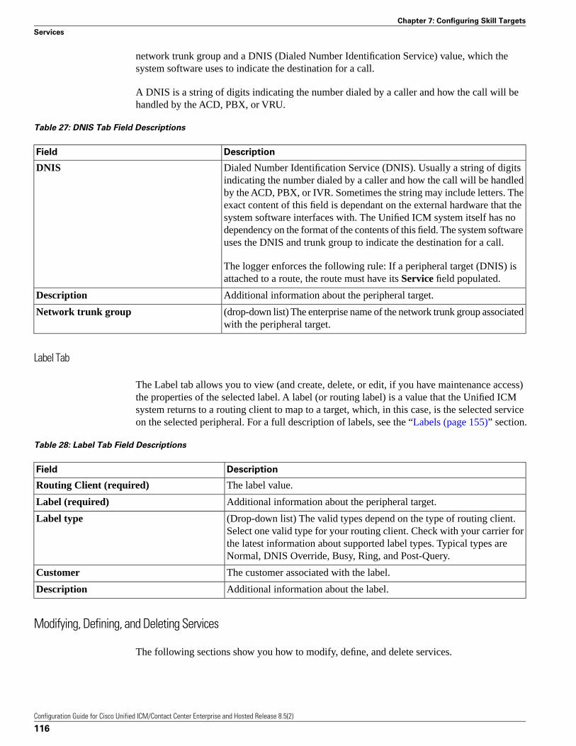
network trunk group and a DNIS (Dialed Number Identification Service) value, which thesystem software uses to indicate the destination for a call.
A DNIS is a string of digits indicating the number dialed by a caller and how the call will behandled by the ACD, PBX, or VRU.
Table 27: DNIS Tab Field Descriptions
DescriptionField
Dialed Number Identification Service (DNIS). Usually a string of digitsindicating the number dialed by a caller and how the call will be handled
DNIS
by the ACD, PBX, or IVR. Sometimes the string may include letters. Theexact content of this field is dependant on the external hardware that thesystem software interfaces with. The Unified ICM system itself has nodependency on the format of the contents of this field. The system softwareuses the DNIS and trunk group to indicate the destination for a call.
The logger enforces the following rule: If a peripheral target (DNIS) isattached to a route, the route must have its Service field populated.
Additional information about the peripheral target.Description
(drop-down list) The enterprise name of the network trunk group associatedwith the peripheral target.
Network trunk group
Label Tab
The Label tab allows you to view (and create, delete, or edit, if you have maintenance access)the properties of the selected label. A label (or routing label) is a value that the Unified ICMsystem returns to a routing client to map to a target, which, in this case, is the selected serviceon the selected peripheral. For a full description of labels, see the “Labels (page 155)” section.
Table 28: Label Tab Field Descriptions
DescriptionField
The label value.Routing Client (required)
Additional information about the peripheral target.Label (required)
(Drop-down list) The valid types depend on the type of routing client.Select one valid type for your routing client. Check with your carrier for
Label type
the latest information about supported label types. Typical types areNormal, DNIS Override, Busy, Ring, and Post-Query.
The customer associated with the label.Customer
Additional information about the label.Description
Modifying, Defining, and Deleting Services
The following sections show you how to modify, define, and delete services.
Configuration Guide for Cisco Unified ICM/Contact Center Enterprise and Hosted Release 8.5(2)
116
Chapter 7: Configuring Skill Targets
Services
How to Modify a Service
To modify a service, do the following:
Step 1 Follow the steps for viewing a service. (See the “How to View a Service (page 113)” section.)
Step 2 Edit the configuration information. (For field descriptions, see the “Service Explorer TabDescriptions (page 113) section.)
Note: You cannot modify fields that are greyed out.
With the mouse, you can select an object and then move it to another part of the tree, as longas its object type belongs in that tree location. For example, to move a route to another service,select it and then move the mouse to that service. When that service becomes highlighted, liftyour finger off the mouse. You can also use the Bulk Configuration tool to take the output of aswitch and create 20 or 30 labels. Then, using the Service Explorer, you can attach the labelsto an appropriate location.
When you make a modification, the Changed icon
Figure 36: Changed icon
appears next to the selected item in the tree list box.
Step 3 Click Save.
The modified data is saved in the Unified ICM database and the Changed icon is removed fromthe edited object in the tree list box.
How to Define a Service and Its Associated Records
To define a service or its associated records, follow these steps:
Step 1 In the Configuration Manager menu, select Tools > Explorer Tools > Service Explorer. TheService Explorer window appears.
Step 2 In the Select filter data box of the Explorer window, click Retrieve. This enables the AddService button.
Step 3 Click Add Service. A new service appears in the tree list box with a To Be Inserted icon
Figure 37: To be inserted icon
next to it. Tabbed fields also appear on the right for the configuration information for the newservice.
Configuration Guide for Cisco Unified ICM/Contact Center Enterprise and Hosted Release 8.5(2)
117
Chapter 7: Configuring Skill Targets
Services
Step 4 Fill in the tabbed fields. (For field descriptions, see the “Service Explorer Tab Descriptions(page 113)” section.)
Step 5 Click Add Route and fill in its configuration records.
Step 6 Click Add Peripheral Target and Add Label and fill in those records.
Selecting an item in the tree list box enables the Add button for more items of that type and forthe associated item immediately beneath it in the tree, if it can have one.
Step 7 If desired, set security settings on the records. (See the “How to View or Apply Security Settings(page 63)” section.)
Step 8 Click Save.
How to Delete a Record
To delete a record:
Step 1 In the Explorer tree list box, select the item or associated items whose records you want todelete.
Note: Deleting any item in the tree list box with branches beneath it also deletes those branches.For example, if you delete a service, you also delete its associated route, peripheral target, andlabel, if it has such. But, deleting a label deletes only that label.
Step 2 Click Delete. This places a Marked for Deletion icon
Figure 38: Marked for deletion icon
next to the selected item in the tree list box. This also toggles the Delete button to Undelete.
To undelete an item marked for deletion, select it in the tree list box and click Undelete.
Step 3 Click Save.
This deletes from the database the item(s) marked for deletion and removes it from the tree listbox. Once you do this, you cannot undelete the deleted item.
Skill Groups
Enter information about each skill group associated with each peripheral. A skill group is acollection of agents that share a common set of skills and is associated with a service. Each skillgroup can be a member of more than one service.
Use the Configuration Manager Skill Group Explorer to view, modify, or define a skill group.
Configuration Guide for Cisco Unified ICM/Contact Center Enterprise and Hosted Release 8.5(2)
118
Chapter 7: Configuring Skill Targets
Skill Groups
Skill Group Explorer
The following sections show you how to use the Skill Group Explorer to view and configure askill group and its associated routes, peripheral targets, and labels.
How to View a Skill Group
To view a skill group, follow these steps:
Step 1 In the Configuration Manager menu, select Tools > Explorer Tools > Skill Group Explorer.The Skill Group Explorer window appears.
Step 2 In the Select filter data box, select the peripheral associated with the skill group you want toview. You can choose the name from the drop-down list of peripheral enterprise names.
Step 3 Select any other filters you want. None in the Optional filter box means all skill groups associatedwith the selected peripheral will be displayed.
Step 4 Click Retrieve. This lists in the tree list box the name(s) of the retrieved service(s).
Step 5 In the tree list box, select a service to display its configuration information on the right side ofthe window.
Step 6 If the skill group has a route associated with it, click its icon in the tree list box to display itsconfiguration information. Do the same for a peripheral target associated with the route and alabel associated with the peripheral target.
Note: A tree object is unassigned if it was made by another configuration tool and was notassigned (mapped) to a parent object; for example, a label might not have been assigned to aperipheral target or a route might not have been assigned to a service, and so on.
Skill Group Explorer Tab Descriptions
The tables in the following sections describe the tabbed fields in the Skill Group Explorerrecords.
Skill Group Tab
The Skill Group tab allows you to view (and edit, if you have maintenance access) the propertiesof the currently selected skill group. A skill group is a collection of agents that share a commonset of skills.
Table 29: Skill Group Tab Field Descriptions
DescriptionField
(selection list) The media routing domain associated with the skill group.Media routing domain (required)
Configuration Guide for Cisco Unified ICM/Contact Center Enterprise and Hosted Release 8.5(2)
119
Chapter 7: Configuring Skill Targets
Skill Groups
DescriptionField
Note: A media routing domain (MRD) can associate with one or more skillgroups, but a skill group can associate with only one media routing domain.
The skill group number as known by the peripheral. This value must be uniqueamong all skill groups for a peripheral, but need not be unique acrossperipherals.
Peripheral Number (required)
The local name for this skill group. This value must be unique among all skillgroups associated with the peripheral, but need not be unique across peripherals.
Peripheral Name (required)
For example, each peripheral can have a skill group namedInternational_Orders. For skill groups that support sub-skill groups, thesub-skill group name is made out of the base skill group name plus a suffix.A suffix can have a maximum of 4 characters. Therefore, the maximum lengthfor a base skill group name is 28 characters when you plan to have sub-skillgroups.
Note: The peripheral name in the filter box is its enterprise name, not thisname.
An enterprise name for the skill group. This name must be unique among allskill groups in the enterprise. If you click in this box after entering the
Name (required)
peripheral name, the software automatically creates this name by appendingthe peripheral name to the selected peripheral. For example:Boston_PG1.Internaltional_Orders.
The number of seconds to wait after a call ends before recording the agent asAvailable.
Available Holdoff Delay
You can enter a value or choose the default.
• For a DMS-100, enter the Variable WrapUp time for the ACD DN.
• For all other peripheral types, set this field to zero.
(read-only) Indicates the routing priority of this base group for the skill. Thevalue 0 indicates a base skill group. This is the default when there is only one
Priority
skill group and there are no priorities. For sub skill group priorities please seethe Sub Skill Group tab as well as the Subgroup Mask tab.
If the peripheral is an Avaya DEFINITY ECS or Rockwell Spectrum, enterthe extension number associated with the skill group. For all other peripheraltypes, leave this field blank.
Extension
Checked, indicates that the system software selects the agent. This option isused for IPCC-like routing where the system software picks the agent to handlea request.
ICM picks the agent
Unchecked, indicates another entity, typically an ACD, does the agent selection(after the system software has sent a call to an ACD skill group).
This option applies to pre-routed requests.
Configuration Guide for Cisco Unified ICM/Contact Center Enterprise and Hosted Release 8.5(2)
120
Chapter 7: Configuring Skill Targets
Skill Groups
DescriptionField
(optional) A string of parameters the system software sends to the peripheralto initialize the skill group.
ConfigParam
Additional information about the skill group.Description
Indicates that this skill group was originally configured by Peripheral AutoConfig and is no longer used by the peripheral.
No longer used by peripheral
Skill Group Members Tab
The Skill Group Members tab allows you to view skill group member information for thecurrently selected skill group. If you have maintenance access, this tab also lets you add orremove skill group members. It also lets you assign this skill group as the default skill groupfor one or more agents.
Note: This tab is only enabled if there are no sub-skill groups configured for this base skillgroup.
Table 30: Skill Group Members Tab Field Descriptions
DescriptionField/Button
This window lists the names of all the agents that are members of the selectedskill group.
Current skill group members
The name of an agent in the skill group.Agent name
The name of each agent’s default skill group. <System-defined> indicatesthat the agent’s default skill group is the peripheral default skill group.
Current default skill group name
To add a skill group member, click this button. Then in the Add Skill GroupMember window, select the name of an agent from the list of available recordsand click OK.
Add
To remove an agent, select an agent name in the Current skill group memberswindow and click this button.
Remove
To set an agent’s default skill group to the current skill group, select one ormore agent names in the Current skill group members window and click this
Set Default Skill Group
button. This button is disabled if the peripheral is not a CallManager/SoftACDor IPCC System peripheral, or the Media routing domain is not configured asCisco_Voice.
Assigning Agents to a Default Skill Group
Observe the following guidelines when assigning an agent to a default skill group:
• An agent can be a member of multiple skill groups, but can only belong to one default skillgroup. Clicking the Set Default Skill Group button sets the default skill group for all selectedagents to this skill group.
• Removing one or more agents with this skill group set as its default causes the agent’s defaultskill group to be set to the peripheral default skill group.
Configuration Guide for Cisco Unified ICM/Contact Center Enterprise and Hosted Release 8.5(2)
121
Chapter 7: Configuring Skill Targets
Skill Groups
• Changing the Media routing domain from Cisco_Voice to non Cisco_Voice sets the defaultskill group for all member agents having this skill group as their default to the peripheraldefault skill group, and the Set Default Skill Group button is disabled.
Subgroup Mask Tab
The Subgroup Mask tab allows you to view (and edit, if you have maintenance access) thenumber of sub-skill groups on the currently selected peripheral. This tab is enabled only if theselected peripheral can have sub-skill groups. A subgroup mask defines sub-skill groups.
Note:
• Important! Sub-skill groups were supported in earlier releases, but are currently onlysupported for Avaya PG, Symposium PG, IPCC PG, Spectrum PG, and NEC PG TDMperipherals. Sub-skill groups are also not supported for non-voice skill groups. That is, youcannot create sub-skill groups for these media classes: single-session chat, multi-session chat,blended collaboration, and email.
• For all peripherals that support sub-skills (Definity ECS EAS, and Rockwell Spectrum), theSkill Group Explorer automatically creates the sub-skills (primary, secondary, and so on) asdefined by the peripheral subgroup mask. This tab gives you the option of changing thesub-skill mask on a skill-group-by-skill-group basis.
Table 31: Subgroup Mask Tab Field Descriptions
DescriptionField
If this checkbox is not checked, the default sub-skill groups for the selectedperipheral are created. Selecting this checkbox enables the Subskill groupcheckboxes.
Override Peripheral Default Mask
Check the box for each sub-skill group you want to generate.Subskill group check boxes
Uncheck the box for each sub-skill group that you want to delete.
Note: These checkboxes are only enabled for Avaya PG, Symposium PG,IPCC PG, Spectrum PG, and NEC PG TDM peripherals.
Upon saving, the unchecked sub-skill groups are only marked deleted in thedatabase for reporting purposes. To permanently delete these sub-skill groupsonce they are on longer needed, use the Deleted Object tool.
If these sub-skill groups are not permanently deleted, configuring a sub-skillgroup with the same priority by checking off the corresponding checkbox inthe Subgroup mask tab causes the error message “Failed to update thedatabase. The enterprise name that was entered is already in use”.
Configuration Guide for Cisco Unified ICM/Contact Center Enterprise and Hosted Release 8.5(2)
122
Chapter 7: Configuring Skill Targets
Skill Groups
Sub Skill Groups Tab
The Sub Skill Groups tab allows you to view (and edit, if you have maintenance access) thesub-skill group properties of the currently selected peripheral. This tab is enabled only if theselected peripheral has sub-skill groups.
Table 32: Sub Skill Groups Tab Descriptions
DescriptionItem
The list of sub-skill groups associated with the peripheral.Associated sub skill groups
The names of the sub-skill groups associated with the peripheral.Priority
The priority level of the sub-skill groups: 1=primary; 2=secondary; 3=tertiary;and so on. The value 0 indicates a base skill group. This is the default whenthere is only one skill group and there are no priorities.
Agents in the selected sub-group
The list of agents in the selected sub-skill group.Agents in the selected sub-group
The names of the agents in the selected sub-skill groups.Agent name
To add an agent to the selected sub-skill group, click this button, and in theAdd Skill Group Member dialog, select a name and click OK.
Add
To remove an agent from the selected sub-skill group, select that agent’s nameand click Remove.
Remove
Route Tab
The Route tab allows you to view (and define, delete, or edit, if you have maintenance access)the properties of the selected route.
A route is a value returned by a routing script that maps to a target at a peripheral; that is, aservice, skill group, agent, or translation route. In this case, the route maps to a skill group. Formore information about routes, see the “Configuring Routes and Routing Targets (page 147)”section.
Table 33: Route Tab Field Descriptions
DescriptionField
Set to 0 if the route is assigned to the base skill group. If the route is assignedto a sub skill group (as listed on the Sub skill groups tab), select the setting (1,
Skill group priority
2, 3, and so forth) that matches the desired sub skill group from the sub skillgroups list. The number of priority levels available depends upon the subgroupmask setting (1-64) on the Subgroup Mask tab which in turn depends upon theperipheral chosen.
The enterprise name of the route.Name (required)
You might derive the enterprise name for the route from the skill group andservice associated with it. For example, you might have a route associated withthe Dallas.TeleSales service and the Dallas.Sales skill group. You might namethe route Dallas.TS_Sales..
Configuration Guide for Cisco Unified ICM/Contact Center Enterprise and Hosted Release 8.5(2)
123
Chapter 7: Configuring Skill Targets
Skill Groups
DescriptionField
Additional information about the route.Description
(selection list) The name of the service associated with the route.Service Name
Every route must be associated with a service for it to be functional. By choosinga service, you are implicitly associating the route with the peripheral for thatservice. For a new route, the drop-down list contains all the services defined forthe selected peripheral (or PG, in the case of a service array).
If you select None as the service name, then the route cannot be associated witha peripheral and you can move the route to the UNASSIGNED list.
Once a route has a service selected, it can no longer be moved to theUNASSIGNED list. However, it can be moved within the appropriate tool toanother skill target. For example, in the Skill Group Explorer, you can move aroute to another skill group, in the Service Explorer, you can move a route toanother service, and in the Agent Explorer, you can move a route to anotheragent.
Peripheral Target Tab
The Peripheral Target tab allows you to view (and define, delete, or edit, if you have maintenanceaccess) the DNIS properties of the selected peripheral target. A peripheral target is a combinationof a trunk group and a DNIS value.
A peripheral target is associated with a service, skill group, agent, or translation route at aperipheral. Each peripheral target is also associated with a route that can be returned by a routingscript.
A DNIS is a string of digits indicating the number dialed by a caller and how the call will behandled by the ACD, PBX, or VRU.
Note that peripheral target refers to a trunk group and DNIS value. Skill target refers to theentity at the peripheral to which the call is dispatched.
Table 34: Peripheral Target Tab Descriptions
DescriptionField
Dialed Number Identification Service (DNIS). Usually a string of digits indicatingthe number dialed by a caller and how the call will be handled by the ACD, PBX,
DNIS (required)
or IVR. Sometimes the string may include letters. The exact content of this fieldis dependant on the external hardware that the system software interfaces with.The Unified ICM system itself has no dependency on the particular format of thecontents of this field. The system software uses the DNIS and trunk group toindicate the destination for a call.
The logger enforces the following rule: If a peripheral target (DNIS) is attachedto a route, the route must have its Service field populated.
Additional information about the peripheral target.Description
Configuration Guide for Cisco Unified ICM/Contact Center Enterprise and Hosted Release 8.5(2)
124
Chapter 7: Configuring Skill Targets
Skill Groups
DescriptionField
The enterprise name of the network trunk group associated with the peripheraltarget.
Network Trunk Group
Label Tab
The Label tab allows you to view (and create, delete, or edit, if you have maintenance access)the properties of the selected label.
A label (or routing label) is a value that the Unified ICM system returns to a routing client tomap to a target, which, in this case, is the selected skill group on the selected peripheral. For afull description of labels, see the “ Labels (page 155)” section.
Table 35: Label Tab Field Descriptions
DescriptionField
The enterprise name of the routing client associated with the label.Routing client (required)
The logger enforces the following rule: If a peripheral target (DNIS) is attachedto a route, the route must have its Service field populated.
The label value.Label (required)
(drop-down list) The valid types depend on the type of routing client. Selectone valid type for your routing client. Check with your carrier for the latest
Label type (required)
information about supported label types. Typical types are Normal, DNISOverride, Busy, Ring, and Post-Query.
(optional) The customer associated with the label.Customer
Additional information about the label.Description
Modifying, Defining, and Deleting Skill Groups
The following sections show you how to modify, define skill groups. For information abouthow to delete a skill group or any of its records, see the “How to Delete a Record (page 118)”section.
How to Modify a Skill Group
To modify a skill group follow these steps:
Step 1 Follow the steps for viewing a skill group. (See the “How to View a Skill Group (page 119)”section.)
Note: Once you have saved a skill group record to the Unified ICM database, you cannot updatethe Peripheral field.
Step 2 Edit the configuration information. (For field descriptions, see the “Skill Group Explorer TabDescriptions (page 119)” section.)
Configuration Guide for Cisco Unified ICM/Contact Center Enterprise and Hosted Release 8.5(2)
125
Chapter 7: Configuring Skill Targets
Skill Groups
Note: You cannot modify fields that are greyed out.
With the mouse, you can select an object and then move it to another part of the tree, as longas its object type belongs in that tree location. For example, to move a route to another skillgroup, select it and then move the mouse to that skill group. When that skill group becomeshighlighted, lift your finger off the mouse. You can also use the Bulk Configuration tool to takethe output of a switch and create 20 or 30 labels. Then, using the Explorer, you can attach thelabels to an appropriate location.
When you make a modification, the Changed icon
Figure 39: Changed icon
appears next to the selected item in the tree list box.
Step 3 Click Save.
The modified data is saved in the Unified ICM database and the Changed icon is removed fromthe edited object in the tree list box.
How to Define a Skill Group and Its Associated Records
Note: The “Configuring Skill Groups on the Child Central Controller (page 127)” section containsan example of how to configure skill groups for a child deployment, which is documented inthe Cisco Contact Center Gateway Deployment Guide for Cisco Unified ICME/CCE/CCX.
To define a skill group or its associated records follow these steps:
Step 1 In the Configuration Manager menu, select Tools > Explorer Tools > Skill Group Explorer.The Skill Group Explorer window appears.
Step 2 In the Select filter data area of the Explorer window, click Retrieve. This enables the AddSkill Group button.
Step 3 Click Add Skill Group. A new skill group appears in the tree list box with a To Be Insertedicon next to it. Tabbed fields also appear on the right for configuration information for the newskill group.
Step 4 Fill in the tabbed fields. (For field descriptions, see the “Skill Group Explorer Tab Descriptions(page 119)” section.)
Step 5 Click Add Route and fill in its configuration records.
Step 6 Click Add Peripheral Target and Add Label and fill in those records.
Selecting an item in the tree list box enables the Add button for more items of that type and forthe associated item immediately beneath it in the tree, if it can have one.
Configuration Guide for Cisco Unified ICM/Contact Center Enterprise and Hosted Release 8.5(2)
126
Chapter 7: Configuring Skill Targets
Skill Groups
Step 7 If desired, set security settings on the records. (See the “How to View or Apply Security Settings(page 63)” section).
Step 8 Click Save.
Configuring Skill Groups on the Child Central Controller
Access the Configuration Manager on the Child Administration & Data Server to configureskill groups.
How to Configure Skill Groups on the Child Central Controller
Use the Configuration Manager Skill Group Explorer Tool to configure skill groups SG01 andSG02 on the Child Central Controller.
Step 1 Start the Skill Group Explorer Tool .
Step 2 On the Main window of the Agent Explorer Tool, click Retrieve.
Step 3 Click Add Skill Group.
The Skill Group tab appears.
Step 4 Complete all the fields and click OK.
The skill group name appears in the list, as with all Explorer tools.
Step 5 Select the Skill Group Member tab and click Add.
The Add Skill Group Member dialog appears.
Step 6 Select the agents to add to the skill group, then click OK.
The agents become members of the skill group.
Step 7 Select the skill group in the tree list, then click Add Route.
The Route tab appears.
Step 8 Provide the Route Name and click Save.
The route name appears in the tree list and the skill group has been added to the peripheral.
Step 9 Repeat this to add one more skill group.
Step 10 Click Save, then Close to exit the Skill Group Explorer Tool.
Configuration Guide for Cisco Unified ICM/Contact Center Enterprise and Hosted Release 8.5(2)
127
Chapter 7: Configuring Skill Targets
Skill Groups
Mapping Skill Groups to Services
When you define services and skill groups, you can establish the mappings of skill groups toservices. Each skill group can be mapped to zero, one, or more services; each service can bemapped to zero, one, or more skill groups.
You can define some service member skill groups as being primary for the service. The systemsoftware uses the primary attribute in determining the destination for a call to the service. Forexample, the Longest Available Agent (LAA) for a service is really the LAA for the primarygroup or groups configured for that service.
How to Map Skill Groups to Services
To map skill groups to services, follow these steps:
Step 1 Within the Configuration Manager menu, select Tools > Explorer Tools > Service Explorer.The Service Explorer window appears.
Step 2 Select the filters you want and click Retrieve. The retrieved services appear in the list box.
Step 3 Select the service you want and click the Service Members tab.
Step 4 This step depends on whether you want to add or to remove skill group(s):
a. To remove a skill group(s), select the skill group name ( or names) and click Remove.
b. To add a skill group or skill groups, click Add, and in the Add Service Member dialog,select the skill group or groups and click OK.
The available skill groups are all those defined for the selected peripheral.
Step 5 In the Service Members tab, select the Primary checkbox for any skill groups that you want tobe primary.
Step 6 When finished, in the Skill Group Explorer window, click Save.
Modifying the Skill Groups Per Agent Limit
Unified ICM and Unified CCE impose a default limit on the number of skill groups that youcan assign to a single agent. Once this limit is reached, additional skill groups cannot be assigned.The default limit is specified in the Cisco Unified Contact Center Enterprise 8.x SolutionReference Network Design (SRND). The limit considers the total of both skill groups and sub-skillgroups.
If desired, you can use the ConfigLimit Tool to specify your own limit on the number of skillgroups that can be assigned to an agent. For optimum performance, you can specify a limit far
Configuration Guide for Cisco Unified ICM/Contact Center Enterprise and Hosted Release 8.5(2)
128
Chapter 7: Configuring Skill Targets
Modifying the Skill Groups Per Agent Limit
lower than the system default (refer to the Cisco Unified Contact Center Enterprise 8.x SolutionReference Network Design (SRND) for performance considerations in choosing a skill groupsper agent limit).
Warning: Setting a default value for skill groups per agent that is higher than the systemdefault can adversely affect system performance. Cisco will not support configurationsthat exceed the default value.
Caution: The ConfigLimit tool is a command-line tool utility from the bin directory of allUnified ICM/CCE Administration & Data Servers. Access is limited to users with privilegesfor the Setup or Config Groups in Active Directory for the chosen customer instance.(Refer to the Outbound Option Guide for Cisco Unified Contact Center Enterprise & Hostedfor detailed information about the ConfigLimit tool.)
Using the ConfigLimit Tool
To change the skill groups per agent limit in configlimit.exe:
Step 1 Launch a command line window on any Administration Client or Administration & Data Server.
Step 2 Enter configlimit.
Step 3 Optionally, enter cl /show to view the existing limit.
Step 4 To change the limit, enter cl /id 1 value/<new_value> /update
For example, to change the skill groups per agent limit to 5, enter the following text: cl /id1 value/5 /update
Step 5 Press Enter.
Additional Requirements
Lowering the Limit
If you have modified the skill groups per agent limit to be lower than the system default, noadditional changes are necessary. The new, lower limit will be enforced immediately. Note thatthe new limit will not impact agents whose existing skill group membership exceeds the newlimit until the next attempt to add a new skill group for those agents. At that time the new limitwill be enforced, preventing you from adding additional skill groups.
Exceeding the Default Limit
If you have modified the skill groups per agent limit to be higher than the system default (inspite of the Warning given above), certain deployments will require additional changes (listedin the following sections) to your system to use the new limit and will allow you to add additionalskill groups.
Configuration Guide for Cisco Unified ICM/Contact Center Enterprise and Hosted Release 8.5(2)
129
Chapter 7: Configuring Skill Targets
Modifying the Skill Groups Per Agent Limit
Note: If you exceed the default limit and are using CTI OS, do not exceed a maximum of 99skill groups.
IPCC Gateway PG
For IPCC Gateway deployments, modify the following registry keys on your IPCC GatewayPGs to include the new value. A change to the registry will require that the PG service berestarted.
IPCC Enterprise Gateway PIM (Cisco Unified Contact Center Enterprise parent)
HKEY_LOCAL_MACHINE\SOFTWARE\Cisco Systems, Inc.\ICM\< customer_instance
>\PG{n}[A|B]\PG\CurrentVersion\PIMS\pim{m}\ACMIData\Config\MaxSkills
IPCC Express Gateway PIM ( Cisco Unified Contact Center Express parent)
HKEY_LOCAL_MACHINE\SOFTWARE\Cisco Systems, Inc.\ICM\< customer_instance
>\PG{n}[A|B]\PG\CurrentVersion\PIMS\pim{n}\ACMIData\Config\MaxSkills
ERI PG
For ERI deployments, modify the following registry key on your ERI PGs to include the newvalue. A change to the registry will require that the PG service be restarted.
ER Service PIM
HKEY_LOCAL_MACHINE\SOFTWARE\Cisco Systems, Inc.\ICM\< customer_instance
>\PG{n}[A|B]\PG\CurrentVersion\PIMS\pim{n}\ERSData\Config\MaxSkills
Persons
You must associate every agent with a person record. The person stores the sign-in name, firstname, last name, and password. On Unified ICM you can have multiple agents per person. Anagent is an “extension” of a person on a given peripheral.
The Person List tool allows you to list the persons currently defined in the Unified ICM database,to define new ones, and to view, edit, or delete the records of existing ones.
Note: You can create Persons or Agents (or both) in the system software and in the Cisco UnifiedInteraction Manager application. Creating them in one of the preceding makes them availableto all. However, if agents exist in your enterprise in the system software and you want them tobe able to work on an Unified ICM application, you must also enable those existing agents inthat application.
Available person records are records that have not been mapped to any agent records (includinglogically deleted ones) at the peripheral selected in the Agent Explorer. To free a personassociated with a logically deleted agent, use the Configuration Manager Deleted Objects toolto permanently delete the logically deleted agent.
Configuration Guide for Cisco Unified ICM/Contact Center Enterprise and Hosted Release 8.5(2)
130
Chapter 7: Configuring Skill Targets
Persons
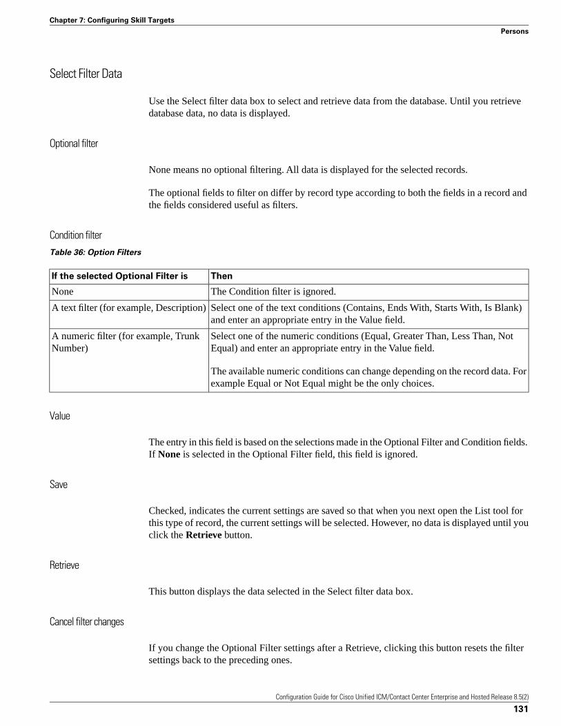
Select Filter Data
Use the Select filter data box to select and retrieve data from the database. Until you retrievedatabase data, no data is displayed.
Optional filter
None means no optional filtering. All data is displayed for the selected records.
The optional fields to filter on differ by record type according to both the fields in a record andthe fields considered useful as filters.
Condition filterTable 36: Option Filters
ThenIf the selected Optional Filter is
The Condition filter is ignored.None
Select one of the text conditions (Contains, Ends With, Starts With, Is Blank)and enter an appropriate entry in the Value field.
A text filter (for example, Description)
Select one of the numeric conditions (Equal, Greater Than, Less Than, NotEqual) and enter an appropriate entry in the Value field.
A numeric filter (for example, TrunkNumber)
The available numeric conditions can change depending on the record data. Forexample Equal or Not Equal might be the only choices.
Value
The entry in this field is based on the selections made in the Optional Filter and Condition fields.If None is selected in the Optional Filter field, this field is ignored.
Save
Checked, indicates the current settings are saved so that when you next open the List tool forthis type of record, the current settings will be selected. However, no data is displayed until youclick the Retrieve button.
Retrieve
This button displays the data selected in the Select filter data box.
Cancel filter changes
If you change the Optional Filter settings after a Retrieve, clicking this button resets the filtersettings back to the preceding ones.
Configuration Guide for Cisco Unified ICM/Contact Center Enterprise and Hosted Release 8.5(2)
131
Chapter 7: Configuring Skill Targets
Persons
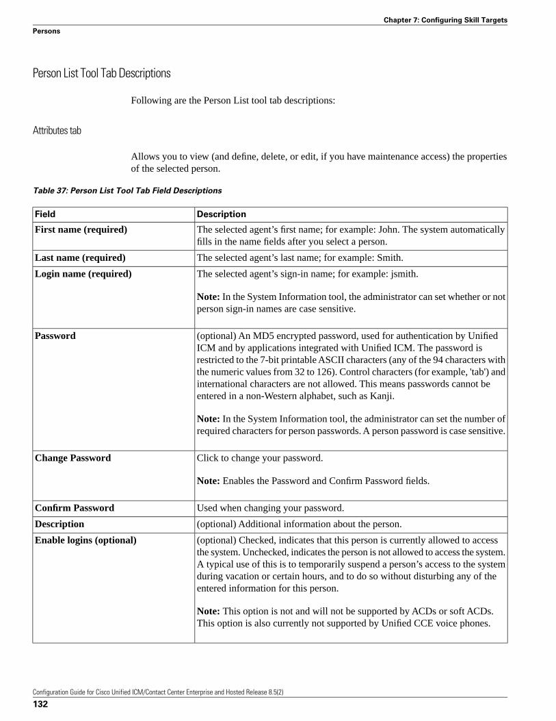
Person List Tool Tab Descriptions
Following are the Person List tool tab descriptions:
Attributes tab
Allows you to view (and define, delete, or edit, if you have maintenance access) the propertiesof the selected person.
Table 37: Person List Tool Tab Field Descriptions
DescriptionField
The selected agent’s first name; for example: John. The system automaticallyfills in the name fields after you select a person.
First name (required)
The selected agent’s last name; for example: Smith.Last name (required)
The selected agent’s sign-in name; for example: jsmith.Login name (required)
Note: In the System Information tool, the administrator can set whether or notperson sign-in names are case sensitive.
(optional) An MD5 encrypted password, used for authentication by UnifiedICM and by applications integrated with Unified ICM. The password is
Password
restricted to the 7-bit printable ASCII characters (any of the 94 characters withthe numeric values from 32 to 126). Control characters (for example, 'tab') andinternational characters are not allowed. This means passwords cannot beentered in a non-Western alphabet, such as Kanji.
Note: In the System Information tool, the administrator can set the number ofrequired characters for person passwords. A person password is case sensitive.
Click to change your password.Change Password
Note: Enables the Password and Confirm Password fields.
Used when changing your password.Confirm Password
(optional) Additional information about the person.Description
(optional) Checked, indicates that this person is currently allowed to accessthe system. Unchecked, indicates the person is not allowed to access the system.
Enable logins (optional)
A typical use of this is to temporarily suspend a person’s access to the systemduring vacation or certain hours, and to do so without disturbing any of theentered information for this person.
Note: This option is not and will not be supported by ACDs or soft ACDs.This option is also currently not supported by Unified CCE voice phones.
Configuration Guide for Cisco Unified ICM/Contact Center Enterprise and Hosted Release 8.5(2)
132
Chapter 7: Configuring Skill Targets
Persons
How to Change Your Password
Follow these steps to change your password:
Step 1 Click Change Password.
Step 2 Enter your new password in the enabled Password field.
Step 3 Re-enter your new password in the enabled Confirm password field to ensure you have typedit correctly.
Step 4 Click Save to set your new password.
Agents
An agent is a person who handles calls from a peripheral or supervises those who do. You needto set up each agent associated with each peripheral.
Use the Configuration Manager Agent Explorer to configure agents.
Note: If partitioning is enabled, you need supervisor privileges to add or remove an agent froma skill group and you need administrator privileges to define an agent record and to edit it inother ways.
The system software also provides a utility that allows you to insert and update agent recordsbased on data in a text file. For more information, see the “Importing Agent Configuration Datafrom the Peripheral (page 139)” section.
How to View or Modify an Agent Record
To view or modify an agent record, follow these steps:
Step 1 In the Configuration Manager menu, select Tools > Explorer Tools > Agent Explorer. TheAgent Explorer window appears.
Step 2 In the Select filter data box, select the peripheral with which the agent is associated. Enter anyother filters you want and click Retrieve.
The retrieved enterprise names for the agents are displayed in the list box.
Step 3 Select the agent name whose properties you want to view and use the tabs on the right side ofthe window to view the properties.
Step 4 Edit the appropriate properties. See the online help if you have questions.
Step 5 When finished, in the Agent Explorer window, click Save.
Configuration Guide for Cisco Unified ICM/Contact Center Enterprise and Hosted Release 8.5(2)
133
Chapter 7: Configuring Skill Targets
Agents
How to Create an Agent
Note: The “Configuring Agents on the Child Central Controller (page 134)” section containsan example of how to configure agents for a child deployment, which is documented in theCisco Contact Center Gateway Deployment Guide for Cisco Unified ICME/CCE/CCX.
Follow these steps to create an agent:
Step 1 In the Configuration Manager menu, select Tools > Explorer Tools > Agent Explorer. TheAgent Explorer window appears.
Step 2 In the Select filter data box, select the peripheral with which the agent is to associated andclick Retrieve. This enables the Add Agent button.
Step 3 Click Add Agent.
Step 4 In the property tabs on the right side of the window, enter the appropriate property values. (Seethe online help for field definitions.) Use the Agent tab (page 135) to define the agent, the Skillgroup membership tab (page 136) to map the agent to any skill groups, and the Supervisor tab(page 137) to assign the agent as a supervisor.
Note: An agent team can have only one primary supervisor. There is no upper limit to thenumber of secondary supervisors for a team. See the online help for instructions on how toassign a primary supervisor.
Step 5 When finished, click Save.
Configuring Agents on the Child Central Controller
Access the Configuration Manager on the Child Administration & Data Server to configureagents.
How to Configure Agents on the Child Central Controller
Use the Configuration Manager Agent Explorer tool to configure agents on the Child CentralController.
Step 1 Start the Agent Explorer tool.
Step 2 On the Main window of the Agent Explorer tool, click Retrieve.
Step 3 Click Add Agent.
The Agent tab appears.
Step 4 Complete all the fields except the Password and the Peripheral Name fields.
Configuration Guide for Cisco Unified ICM/Contact Center Enterprise and Hosted Release 8.5(2)
134
Chapter 7: Configuring Skill Targets
Agents
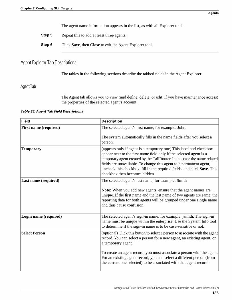
The agent name information appears in the list, as with all Explorer tools.
Step 5 Repeat this to add at least three agents.
Step 6 Click Save, then Close to exit the Agent Explorer tool.
Agent Explorer Tab Descriptions
The tables in the following sections describe the tabbed fields in the Agent Explorer.
Agent Tab
The Agent tab allows you to view (and define, delete, or edit, if you have maintenance access)the properties of the selected agent’s account.
Table 38: Agent Tab Field Descriptions
DescriptionField
The selected agent’s first name; for example: John.First name (required)
The system automatically fills in the name fields after you select aperson.
(appears only if agent is a temporary one) This label and checkboxappear next to the first name field only if the selected agent is a
Temporary
temporary agent created by the CallRouter. In this case the name relatedfields are unavailable. To change this agent to a permanent agent,uncheck this checkbox, fill in the required fields, and click Save. Thischeckbox then becomes hidden.
The selected agent’s last name; for example: SmithLast name (required)
Note: When you add new agents, ensure that the agent names areunique. If the first name and the last name of two agents are same, thereporting data for both agents will be grouped under one single nameand thus cause confusion.
The selected agent’s sign-in name; for example: jsmith. The sign-inname must be unique within the enterprise. Use the System Info toolto determine if the sign-in name is to be case-sensitive or not.
Login name (required)
(optional) Click this button to select a person to associate with the agentrecord. You can select a person for a new agent, an existing agent, ora temporary agent.
Select Person
To create an agent record, you must associate a person with the agent.For an existing agent record, you can select a different person (fromthe current one selected) to be associated with that agent record.
Configuration Guide for Cisco Unified ICM/Contact Center Enterprise and Hosted Release 8.5(2)
135
Chapter 7: Configuring Skill Targets
Agents
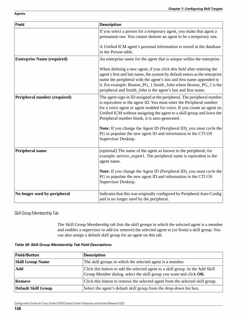
DescriptionField
If you select a person for a temporary agent, you make that agent apermanent one. You cannot demote an agent to be a temporary one.
A Unified ICM agent’s personal information is stored in the databasein the Person table.
An enterprise name for the agent that is unique within the enterprise.Enterprise Name (required)
When defining a new agent, if you click this field after entering theagent’s first and last name, the system by default enters as the enterprisename the peripheral with the agent’s last and first name appended toit. For example: Boston_PG_1.Smith_John where Boston_PG_1 is theperipheral and Smith_John is the agent’s last and first name.
The agent sign-in ID assigned at the peripheral. The peripheral numberis equivalent to the agent ID. You must enter the Peripheral number
Peripheral number (required)
for a voice agent or agent enabled for voice. If you create an agent onUnified ICM without assigning the agent to a skill group and leave thePeripheral number blank, it is auto-generated.
Note: If you change the Agent ID (Peripheral ID), you must cycle thePG to populate the new agent ID and information in the CTI OSSupervisor Desktop.
(optional) The name of the agent as known to the peripheral; forexample: service_expert1. The peripheral name is equivalent to theagent name.
Peripheral name
Note: If you change the Agent ID (Peripheral ID), you must cycle thePG to populate the new agent ID and information in the CTI OSSupervisor Desktop.
Indicates that this was originally configured by Peripheral Auto Configand is no longer used by the peripheral.
No longer used by peripheral
Skill Group Membership Tab
The Skill Group Membership tab lists the skill groups in which the selected agent is a memberand enables a supervisor to add (or remove) the selected agent to (or from) a skill group. Youcan also assign a default skill group for an agent on this tab.
Table 39: Skill Group Membership Tab Field Descriptions
DescriptionField/Button
The skill groups in which the selected agent is a member.Skill Group Name
Click this button to add the selected agent to a skill group. In the Add SkillGroup Member dialog, select the skill group you want and click OK.
Add
Click this button to remove the selected agent from the selected skill group.Remove
Select the agent’s default skill group from the drop-down list box.Default Skill Group
Configuration Guide for Cisco Unified ICM/Contact Center Enterprise and Hosted Release 8.5(2)
136
Chapter 7: Configuring Skill Targets
Agents
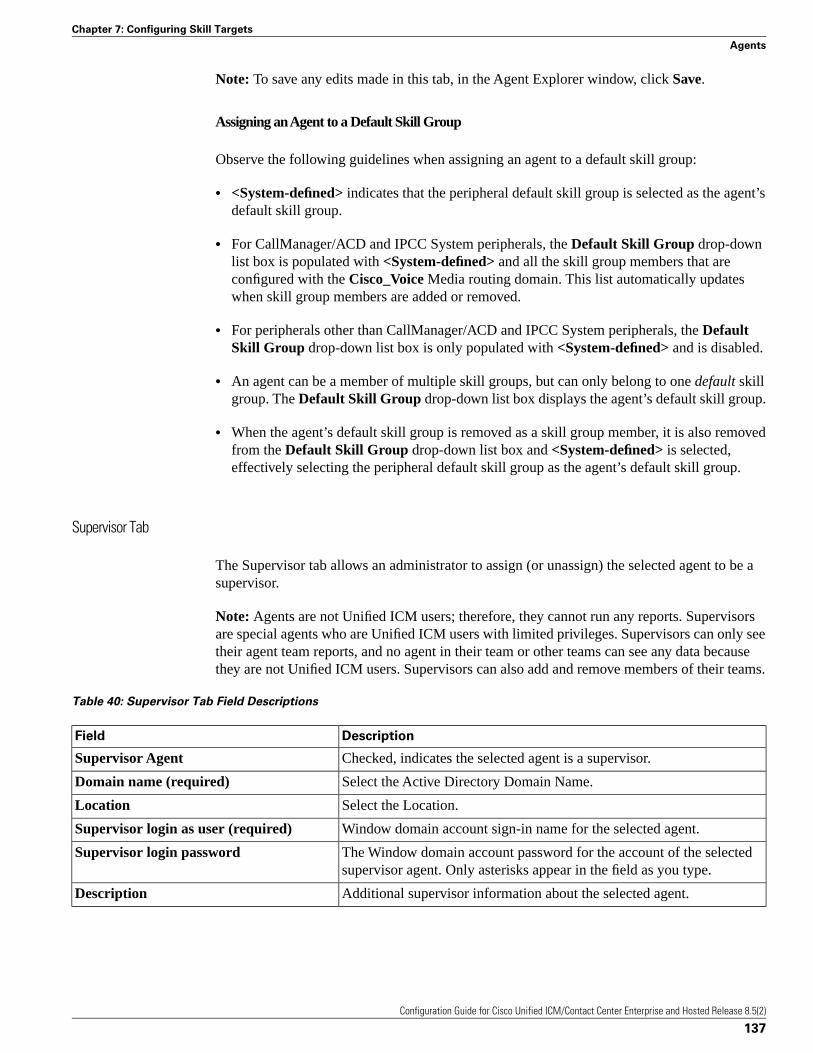
Note: To save any edits made in this tab, in the Agent Explorer window, click Save.
Assigning an Agent to a Default Skill Group
Observe the following guidelines when assigning an agent to a default skill group:
• <System-defined> indicates that the peripheral default skill group is selected as the agent’sdefault skill group.
• For CallManager/ACD and IPCC System peripherals, the Default Skill Group drop-downlist box is populated with <System-defined> and all the skill group members that areconfigured with the Cisco_Voice Media routing domain. This list automatically updateswhen skill group members are added or removed.
• For peripherals other than CallManager/ACD and IPCC System peripherals, the DefaultSkill Group drop-down list box is only populated with <System-defined> and is disabled.
• An agent can be a member of multiple skill groups, but can only belong to one default skillgroup. The Default Skill Group drop-down list box displays the agent’s default skill group.
• When the agent’s default skill group is removed as a skill group member, it is also removedfrom the Default Skill Group drop-down list box and <System-defined> is selected,effectively selecting the peripheral default skill group as the agent’s default skill group.
Supervisor Tab
The Supervisor tab allows an administrator to assign (or unassign) the selected agent to be asupervisor.
Note: Agents are not Unified ICM users; therefore, they cannot run any reports. Supervisorsare special agents who are Unified ICM users with limited privileges. Supervisors can only seetheir agent team reports, and no agent in their team or other teams can see any data becausethey are not Unified ICM users. Supervisors can also add and remove members of their teams.
Table 40: Supervisor Tab Field Descriptions
DescriptionField
Checked, indicates the selected agent is a supervisor.Supervisor Agent
Select the Active Directory Domain Name.Domain name (required)
Select the Location.Location
Window domain account sign-in name for the selected agent.Supervisor login as user (required)
The Window domain account password for the account of the selectedsupervisor agent. Only asterisks appear in the field as you type.
Supervisor login password
Additional supervisor information about the selected agent.Description
Configuration Guide for Cisco Unified ICM/Contact Center Enterprise and Hosted Release 8.5(2)
137
Chapter 7: Configuring Skill Targets
Agents
Mapping Agents to Skill Groups
After you have set up skill groups and agents, enter the assignments of agents to skill groupsas configured for the peripheral. Each agent can belong to zero, one, or more skill groups.
You can use the Configuration Manager Skill Group Explorer to map agents to skill groups.
How to Assign Agents to a Skill Group
Follow these steps to assign agents to a skill group:
Step 1 Within the Configuration Manager menu, select Tools > Explorer Tools > Agent Explorer.The Agent Explorer window appears.
Step 2 Select the filters you want and click Retrieve. The retrieved agents appear in the list box.
Step 3 Select the agent you want assign to a skill group and click the Skill Group Membership tab.
Step 4 This step depends on whether you want to add or to remove agent. On the Skill group membershiptab:
a. To remove the selected agent from a skill group, select the appropriate skill group orgroups, and then click Remove.
b. To add the selected agent to a skill group, click Add, and in the Add Skill Group Memberdialog, select the appropriate skill group or groups and click OK.
Step 5 When finished, click Save in the Agent Explorer window.
How to Enable/Disable Agent Data at a Peripheral and Define an Agent Distribution
Follow these steps to enable/disable agent data at a peripheral and define an agent distribution:
Step 1 In the Configuration Manager menu, select Tools > Explorer Tools > PG Explorer. The PGExplorer window appears.
Step 2 Click Retrieve.
Step 3 In the tree list box, expand the appropriate logical controller and select the peripheral.
Step 4 In the Agent Distribution tab, select or deselect the Enable agent reporting checkbox.
Step 5 In the Agent Distribution Entries list box, select an existing distribution site or create a new oneby clicking New and entering values for the following fields:
a. Administration & Data Server site name. The Admin site name for thePrimary/Secondary Pair (Site) name, as specified in the Web Setup tool.
Configuration Guide for Cisco Unified ICM/Contact Center Enterprise and Hosted Release 8.5(2)
138
Chapter 7: Configuring Skill Targets
Agents
b. Agent real time data. If checked, enables the flow of agent real time data from theperipheral to the Administration & Data Server. Unchecked, disables the flow of agentreal time data.
c. Agent historical data. If checked, enables the flow of agent historical data from theperipheral to the Administration & Data Server. Unchecked, disables the flow of agenthistorical data.
Step 6 Click Save to apply your changes.
Agent State Trace
Optionally, the system software can track every state (Available, Talking, and so on) an agentpasses through. You can turn on this feature in the Configuration Manager Agent Explorer. TheAgent tab includes the Agent State Trace checkbox, which you select if you want to track thisagent’s states.
Note: Tracking every state of an agent puts an added load on the system software. Activatingthis feature for all agents at all times may require additional network bandwidth, additionaldatabase space, and so on. Typically, you must use this feature only for short-term tracking ofspecific agents.
Temporary Agents
The system software might receive agent-level reporting data for an agent that has not beenconfigured. The system software automatically configures a temporary agent to associate withthis data.
The Agent Explorer Agent tab includes a Temporary Agent checkbox. This checkbox isdisabled and unchecked for standard agents. For temporary agents created by the CallRoutersoftware, this checkbox is enabled and checked.
The system software derives the last name, first name, and enterprise name from the peripheralnumber and skill target ID.
You can subsequently modify the agent configuration to assign the correct names to the agent.To convert a temporary agent to a standard agent, uncheck the Temporary Agent checkbox.When you apply these modifications, the Temporary Agent field is automatically deselectedand disabled.
Importing Agent Configuration Data from the Peripheral
An ACD requires all the available agents to be configured to allow the agents to sign-in to thecall handling devices with their peripheral number (Agent ID) or peripheral name, password,and so on. Also, these agents are configured to handle specific category of calls based on SkillGroup. There are some other data elements configured on the ACD such as last name, first nameand other class of services.
Configuration Guide for Cisco Unified ICM/Contact Center Enterprise and Hosted Release 8.5(2)
139
Chapter 7: Configuring Skill Targets
Agents
The Unified ICM Agent Level Reporting requires these agents to be configured in Unified ICMto identify them with either full name, peripheral name or enterprise name on both the real-timeand historical reports.
The agentcfg.exe command line tool provides a process for configuring the agent configurationdata elements available on an ACD in the Agent table in the Unified ICM database. This canalso be automated by scheduling the process to run as an AT job at a specific time of day. Thefrequency of scheduling the agent configuration process depends on your requirements.
The Agent configuration process is required to run for each peripheral.
How to Import Agent Data
Follow these steps to import agent data:
Step 1 Retrieve the agent configuration data from the peripheral.
Step 2 Form all the information in a tab-delimited text file with one row per agent. Each row of thefile must contain the following fields, in order:
PeripheralNumber FirstName LastName Description PeripheralName
Step 3 To import data from the file into the system software, enter one of the following commands atthe command prompt: AgentCfg <Peripheral ID or Peripheral Name> <Inputfile name> [<Second input file>] [<Option>]
These variables are defined as:
a. <Peripheral ID or Peripheral Name>:
Peripheral ID or Peripheral Name of the peripheral that you want to configure.
b. <Input file name>:
The name of the input file contains the agent OR skill group member configuration data on theACD in the appropriate format (described in the next section). The file must contain headerinformation, otherwise the tool assumes the data is for the Agent table.
Full or relative path is allowed.
c. <Second input file>:
If the first file contained Agent data, the second file must contain Skill Group Member data. Ifthe first file contained Skill Group Member data, the second file must contain Agent data.
If no files contain headers, it is assumed that Agent data is in the first file and Skill GroupMember data is in the second file. If headers are provided, the files may be specified in eitherorder.
Full or relative path is allowed.
Configuration Guide for Cisco Unified ICM/Contact Center Enterprise and Hosted Release 8.5(2)
140
Chapter 7: Configuring Skill Targets
Agents
d. <Option>:
/show Only - show configuration changes without committing to the database.
/nodelete - the tool will not perform any delete operations. All inserts and updates will be saved.
Example:
1. AgentCfg.exe peripheral1 c:\temp\agentData.txt c:\temp\skillGrpMemData.txt
This example will configure both agent and skill group member data for peripheral1.
2. AgentCfg.exe peripheral1 c:\temp\skillGrpMemData.txt
This example will configure skill group member data for peripheral. The file must containheader information.
Step 4 When the system software invokes the AgentCfg command, it performs the following steps foreach line in the input file:
The following steps are performed for each line in the input file:
1. The system software attempts to match the PeripheralNumber value to a configured agentfor the peripheral.
If it finds a match, it proceeds directly to step 2.
If it cannot find a match, it creates a new agent row in the database using the data fromthe input file, and proceeds to step 2.
2. The system software checks to see if the “temporary” flag is set. If it is, it then updatesthe existing record.
3. The system software checks whether the peripheral name values also match.
If the FirstName and LastName values match, then the system software updates the existingrecord with the Description and PeripheralName values. (If the existing record was for atemporary agent, the agent is no longer temporary after the update.)
If the values do not match, then the system software marks the existing record as deletedand inserts a new row with the data from the input file. If an agent is configured for theperipheral in the database, but is not listed in the input file, then the system software marksthe agent as deleted in the database.
4. The system software does a loop through the Skill Group Member input file container andcompares the records in file and those in database:
– If the record is found in file but does not exist in the database, the record is inserted.
– If the record is found in the database but does not exist in the file, the record is deleted.
Configuration Guide for Cisco Unified ICM/Contact Center Enterprise and Hosted Release 8.5(2)
141
Chapter 7: Configuring Skill Targets
Agents
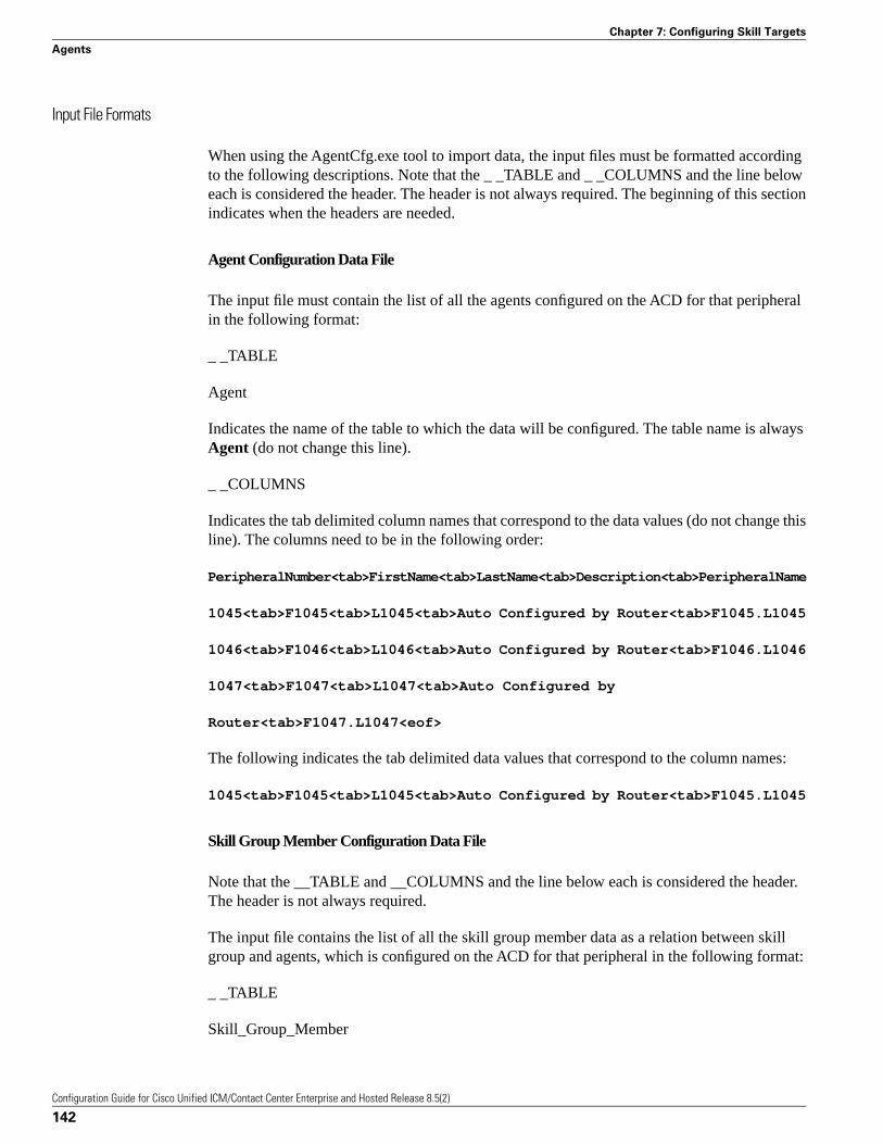
Input File Formats
When using the AgentCfg.exe tool to import data, the input files must be formatted accordingto the following descriptions. Note that the _ _TABLE and _ _COLUMNS and the line beloweach is considered the header. The header is not always required. The beginning of this sectionindicates when the headers are needed.
Agent Configuration Data File
The input file must contain the list of all the agents configured on the ACD for that peripheralin the following format:
_ _TABLE
Agent
Indicates the name of the table to which the data will be configured. The table name is alwaysAgent (do not change this line).
_ _COLUMNS
Indicates the tab delimited column names that correspond to the data values (do not change thisline). The columns need to be in the following order:
PeripheralNumber<tab>FirstName<tab>LastName<tab>Description<tab>PeripheralName
1045<tab>F1045<tab>L1045<tab>Auto Configured by Router<tab>F1045.L1045
1046<tab>F1046<tab>L1046<tab>Auto Configured by Router<tab>F1046.L1046
1047<tab>F1047<tab>L1047<tab>Auto Configured by
Router<tab>F1047.L1047<eof>
The following indicates the tab delimited data values that correspond to the column names:
1045<tab>F1045<tab>L1045<tab>Auto Configured by Router<tab>F1045.L1045
Skill Group Member Configuration Data File
Note that the __TABLE and __COLUMNS and the line below each is considered the header.The header is not always required.
The input file contains the list of all the skill group member data as a relation between skillgroup and agents, which is configured on the ACD for that peripheral in the following format:
_ _TABLE
Skill_Group_Member
Configuration Guide for Cisco Unified ICM/Contact Center Enterprise and Hosted Release 8.5(2)
142
Chapter 7: Configuring Skill Targets
Agents
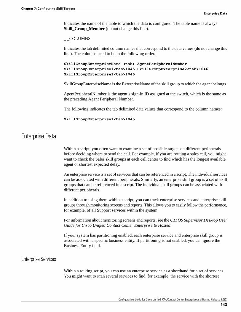
Indicates the name of the table to which the data is configured. The table name is alwaysSkill_Group_Member (do not change this line).
_ _COLUMNS
Indicates the tab delimited column names that correspond to the data values (do not change thisline). The columns need to be in the following order.
SkillGroupEnterpriseName <tab> AgentPeripheralNumber
SkillGroupExterprise1<tab>1045 SkillGroupExterprise2<tab>1046
SkillGroupExterprise1<tab>1046
SkillGroupEnterpriseName is the ExterpriseName of the skill group to which the agent belongs.
AgentPeripheralNumber is the agent’s sign-in ID assigned at the switch, which is the same asthe preceding Agent Peripheral Number.
The following indicates the tab delimited data values that correspond to the column names:
SkillGroupExterprise1<tab>1045
Enterprise Data
Within a script, you often want to examine a set of possible targets on different peripheralsbefore deciding where to send the call. For example, if you are routing a sales call, you mightwant to check the Sales skill groups at each call center to find which has the longest availableagent or shortest expected delay.
An enterprise service is a set of services that can be referenced in a script. The individual servicescan be associated with different peripherals. Similarly, an enterprise skill group is a set of skillgroups that can be referenced in a script. The individual skill groups can be associated withdifferent peripherals.
In addition to using them within a script, you can track enterprise services and enterprise skillgroups through monitoring screens and reports. This allows you to easily follow the performance,for example, of all Support services within the system.
For information about monitoring screens and reports, see the CTI OS Supervisor Desktop UserGuide for Cisco Unified Contact Center Enterprise & Hosted.
If your system has partitioning enabled, each enterprise service and enterprise skill group isassociated with a specific business entity. If partitioning is not enabled, you can ignore theBusiness Entity field.
Enterprise Services
Within a routing script, you can use an enterprise service as a shorthand for a set of services.You might want to scan several services to find, for example, the service with the shortest
Configuration Guide for Cisco Unified ICM/Contact Center Enterprise and Hosted Release 8.5(2)
143
Chapter 7: Configuring Skill Targets
Enterprise Data
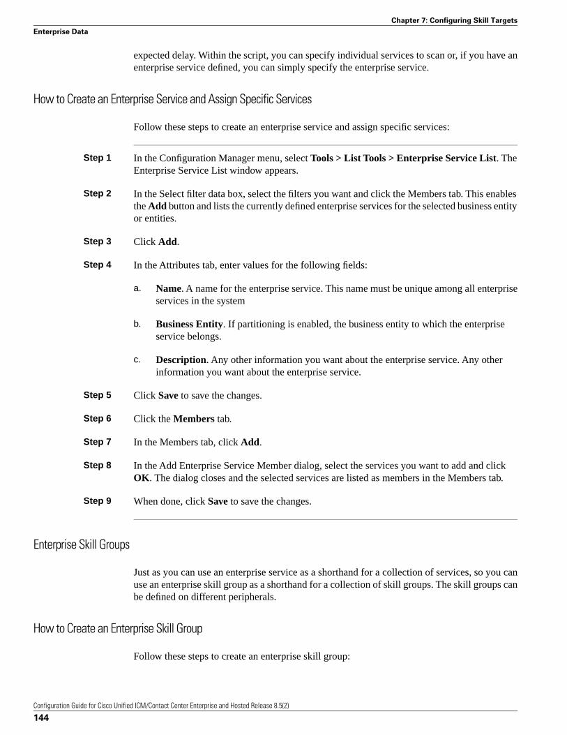
expected delay. Within the script, you can specify individual services to scan or, if you have anenterprise service defined, you can simply specify the enterprise service.
How to Create an Enterprise Service and Assign Specific Services
Follow these steps to create an enterprise service and assign specific services:
Step 1 In the Configuration Manager menu, select Tools > List Tools > Enterprise Service List. TheEnterprise Service List window appears.
Step 2 In the Select filter data box, select the filters you want and click the Members tab. This enablesthe Add button and lists the currently defined enterprise services for the selected business entityor entities.
Step 3 Click Add.
Step 4 In the Attributes tab, enter values for the following fields:
a. Name. A name for the enterprise service. This name must be unique among all enterpriseservices in the system
b. Business Entity. If partitioning is enabled, the business entity to which the enterpriseservice belongs.
c. Description. Any other information you want about the enterprise service. Any otherinformation you want about the enterprise service.
Step 5 Click Save to save the changes.
Step 6 Click the Members tab.
Step 7 In the Members tab, click Add.
Step 8 In the Add Enterprise Service Member dialog, select the services you want to add and clickOK. The dialog closes and the selected services are listed as members in the Members tab.
Step 9 When done, click Save to save the changes.
Enterprise Skill Groups
Just as you can use an enterprise service as a shorthand for a collection of services, so you canuse an enterprise skill group as a shorthand for a collection of skill groups. The skill groups canbe defined on different peripherals.
How to Create an Enterprise Skill Group
Follow these steps to create an enterprise skill group:
Configuration Guide for Cisco Unified ICM/Contact Center Enterprise and Hosted Release 8.5(2)
144
Chapter 7: Configuring Skill Targets
Enterprise Data
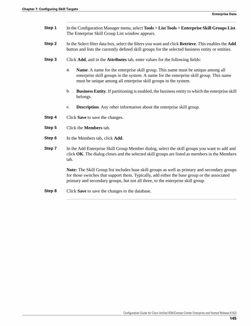
Step 1 In the Configuration Manager menu, select Tools > List Tools > Enterprise Skill Groups List.The Enterprise Skill Group List window appears.
Step 2 In the Select filter data box, select the filters you want and click Retrieve. This enables the Addbutton and lists the currently defined skill groups for the selected business entity or entities.
Step 3 Click Add, and in the Attributes tab, enter values for the following fields:
a. Name. A name for the enterprise skill group. This name must be unique among allenterprise skill groups in the system. A name for the enterprise skill group. This namemust be unique among all enterprise skill groups in the system.
b. Business Entity. If partitioning is enabled, the business entity to which the enterprise skillbelongs.
c. Description. Any other information about the enterprise skill group.
Step 4 Click Save to save the changes.
Step 5 Click the Members tab.
Step 6 In the Members tab, click Add.
Step 7 In the Add Enterprise Skill Group Member dialog, select the skill groups you want to add andclick OK. The dialog closes and the selected skill groups are listed as members in the Memberstab.
Note: The Skill Group list includes base skill groups as well as primary and secondary groupsfor those switches that support them. Typically, add either the base group or the associatedprimary and secondary groups, but not all three, to the enterprise skill group.
Step 8 Click Save to save the changes to the database.
Configuration Guide for Cisco Unified ICM/Contact Center Enterprise and Hosted Release 8.5(2)
145
Chapter 7: Configuring Skill Targets
Enterprise Data

Configuration Guide for Cisco Unified ICM/Contact Center Enterprise and Hosted Release 8.5(2)
146
Chapter 7: Configuring Skill Targets
Enterprise Data
Configuring Routes and Routing TargetsThis chapter describes how to configure the information that routing clients use to interpret theresponse from the system software and route the call to its destination.
It includes:
• An overview of the routes and targets subsystem
• Information about how to configure routes, network targets, and labels
• A discussion of mapping labels to dialed numbers
• Information about service arrays
• Instructions for using the Application Wizard
• A discussion of default route and default label
• Information about scheduled targets and translation routes
This chapter contains the following topics:
• The Routes and Target Subsystem, page 148• Route Configuration, page 150• Network Targets, page 152• Announcement Configuration Information , page 154• Labels, page 155• Service Arrays, page 159• Application Wizard, page 161• How to Use the Application Wizard , page 161• Scheduled Targets, page 165• Translation Routes, page 168• Translation Route Wizard, page 169
Configuration Guide for Cisco Unified ICM/Contact Center Enterprise and Hosted Release 8.5(2)
147
Chapter 8
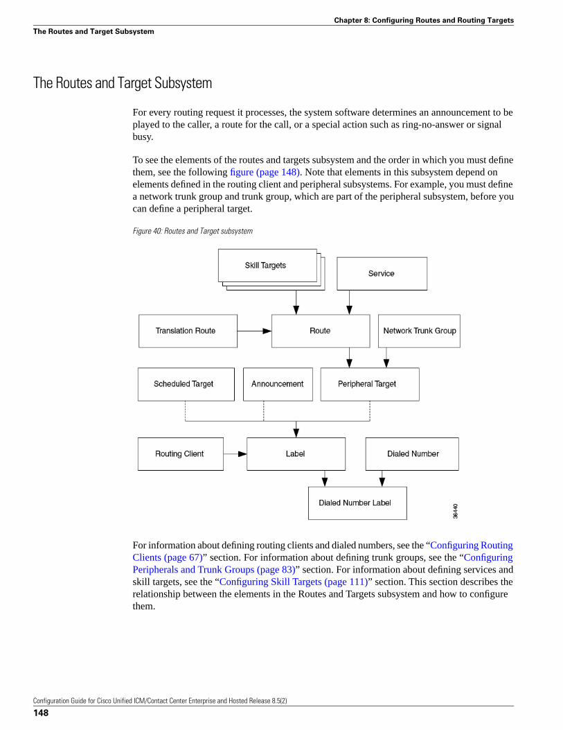
The Routes and Target Subsystem
For every routing request it processes, the system software determines an announcement to beplayed to the caller, a route for the call, or a special action such as ring-no-answer or signalbusy.
To see the elements of the routes and targets subsystem and the order in which you must definethem, see the following figure (page 148). Note that elements in this subsystem depend onelements defined in the routing client and peripheral subsystems. For example, you must definea network trunk group and trunk group, which are part of the peripheral subsystem, before youcan define a peripheral target.
Figure 40: Routes and Target subsystem
For information about defining routing clients and dialed numbers, see the “Configuring RoutingClients (page 67)” section. For information about defining trunk groups, see the “ConfiguringPeripherals and Trunk Groups (page 83)” section. For information about defining services andskill targets, see the “Configuring Skill Targets (page 111)” section. This section describes therelationship between the elements in the Routes and Targets subsystem and how to configurethem.
Configuration Guide for Cisco Unified ICM/Contact Center Enterprise and Hosted Release 8.5(2)
148
Chapter 8: Configuring Routes and Routing Targets
The Routes and Target Subsystem
Cisco Unified Intelligent Contact Management Routing Targets
The system software can route a call to a carrier resource such as an announcement or to a targetat a peripheral. A peripheral, such as an ACD, PBX, or Unified CM dispatches calls within acontact center.
Peripheral Targets
Depending on the capabilities of the peripheral and the type of routing instructions you use, thesystem software might choose a specific agent at the peripheral to handle the call. In that case,the peripheral merely dispatches the call to the chosen agent. In other cases, the system softwaremight specify only a group of agents or a type of service to be provided to the caller.
The system software can route to three types of peripheral targets:
• Agent. A specific individual who receives calls through the peripheral. (The system software,however, cannot guarantee that the specific agent will be available when the call arrives.)The Queue to Agent node allows the targeting of a task (the work performed by an agent) toa script-specified agent. This node enables an agent to receive and operate on more than onetask at a time.
• Skill group. A group of agents who share a common set of skills and who can, therefore, allhandle specific types of calls. Each skill group contains one or more agents. If supported bythe peripheral, each agent can be a member of more than one skill group.
• Service. A type of processing the caller requires. For example, a peripheral might haveservices defined for sales, technical support, or opening new accounts. Each service has oneor more skill groups whose members can provide the service. Each skill group can beassociated with more than one service.
In the last two cases, the peripheral must choose a specific agent within the group who canprovide the service. In each case, the peripheral plays a key role in completing the routing thatthe system software has determined. Therefore, the system software and the peripheral must beset up to complement each other. They must have the same understanding of the agents, skillgroups, and services available at each site.
For specific information about how the system software routes a call and its coordination withperipherals, see the “ How Routing Works (page 11)” section.
Scheduled Targets
Some routing clients also support scheduled targets. A scheduled target is a group of agents notassociated with a Peripheral Gateway. The system software cannot monitor the group directly.Instead it relies on a periodic schedule to determine the number of agents logged on to the group.The routing client informs the system software when a call to the group ends. Because the systemsoftware knows how many calls it has routed to the group, it can determine the number of callsin progress. Based on this and the schedule, the system software can determine whether thetarget can handle an additional call.
Configuration Guide for Cisco Unified ICM/Contact Center Enterprise and Hosted Release 8.5(2)
149
Chapter 8: Configuring Routes and Routing Targets
The Routes and Target Subsystem
Route Configuration
A route consists of two components:
• The skill target (agent, skill group, service, translation route, or service array) at a peripheralwhich can handle a call.
• The service by which the peripheral classifies the call.
Note: You must have defined the skill target and service before you can configure a route.Follow the steps in the Configuration Manager Step by Step Configuration menu whenconfiguring your Unified ICM system.
How to Define and Update a Route
In the Configuration Manager, you can define and update many routes at a time using the RouteBulk tool. Or you can create and update a route using one of the following Explorer tools:
• Agent Explorer
• Skill Group Explorer
• Service Explorer
• Service Array Explorer
• Translation Route Explorer
With the Explorer tools, you can define and update a route at the same time you define andupdate its target. You can access all the tools for creating routes from the Configuration ManagerICM Configure > Targets > Route menu. (See the following figure (page 151).)
Configuration Guide for Cisco Unified ICM/Contact Center Enterprise and Hosted Release 8.5(2)
150
Chapter 8: Configuring Routes and Routing Targets
Route Configuration
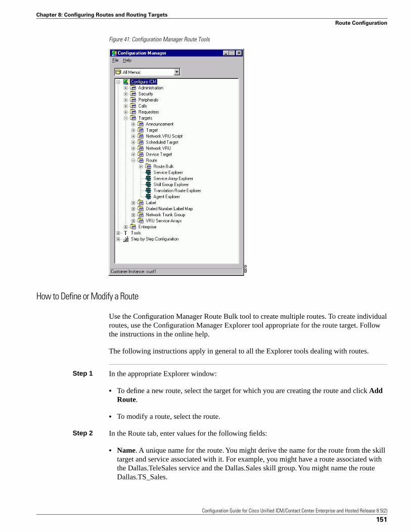
Figure 41: Configuration Manager Route Tools
How to Define or Modify a Route
Use the Configuration Manager Route Bulk tool to create multiple routes. To create individualroutes, use the Configuration Manager Explorer tool appropriate for the route target. Followthe instructions in the online help.
The following instructions apply in general to all the Explorer tools dealing with routes.
Step 1 In the appropriate Explorer window:
• To define a new route, select the target for which you are creating the route and click AddRoute.
• To modify a route, select the route.
Step 2 In the Route tab, enter values for the following fields:
• Name. A unique name for the route. You might derive the name for the route from the skilltarget and service associated with it. For example, you might have a route associated withthe Dallas.TeleSales service and the Dallas.Sales skill group. You might name the routeDallas.TS_Sales.
Configuration Guide for Cisco Unified ICM/Contact Center Enterprise and Hosted Release 8.5(2)
151
Chapter 8: Configuring Routes and Routing Targets
Route Configuration
• Description. Text identifying the route.
• Service name. (selection list) Every route must be associated with a service. By choosing aservice, you are implicitly associating the route with the peripheral for that service. For anew route, the drop-down list contains all the services defined for the selected peripheral (orPG, in the case of a service array).
To assign the route to another service, in the tree list, drag it to the desired peripheral. Youcan also move the route to the UNASSIGNED list.
Warning: When you break the association between a route and a peripheral, the systemsoftware removes the Route ID value from all peripheral targets that reference that route.
Step 3 Click Save. The system software saves your changes in the database.
How to Set a Default Route for a Peripheral
After you have defined routes, you can set a default route for each peripheral. The systemsoftware uses the default route to classify calls for statistical purposes.
For each call that arrives at a peripheral, the system software records monitoring informationin the real-time and historical tables for the route associated with that call. If the system softwarecannot determine a route for the call, it uses the default route defined for the peripheral.
By defining a default route for each peripheral, you ensure that the system software capturesroute information for every call. You might want to create a special route for this purpose. Youcan then determine which calls are not being accounted for properly.
Step 1 In the Configuration Manager menu, select Tools > Explorer Tools > PG Explorer. The PGExplorer window appears.
Step 2 In the tree list window, select the peripheral you want to modify and click the Advanced tab.
Step 3 In the Default route field, select the enterprise name of a route from the selection list. The listincludes all routes associated with skill targets at the chosen peripheral.
Step 4 After choosing the route, click Save to enter your edits into the database.
Network Targets
Routing clients do not send calls directly to services, skill groups, or agents. They send eachcall to an announcement or to a specific trunk group at a peripheral. If the call is sent to a trunkgroup, the routing client can also send a DNIS value for the call. The combination of trunkgroup and DNIS value is a peripheral target.
Configuration Guide for Cisco Unified ICM/Contact Center Enterprise and Hosted Release 8.5(2)
152
Chapter 8: Configuring Routes and Routing Targets
Network Targets
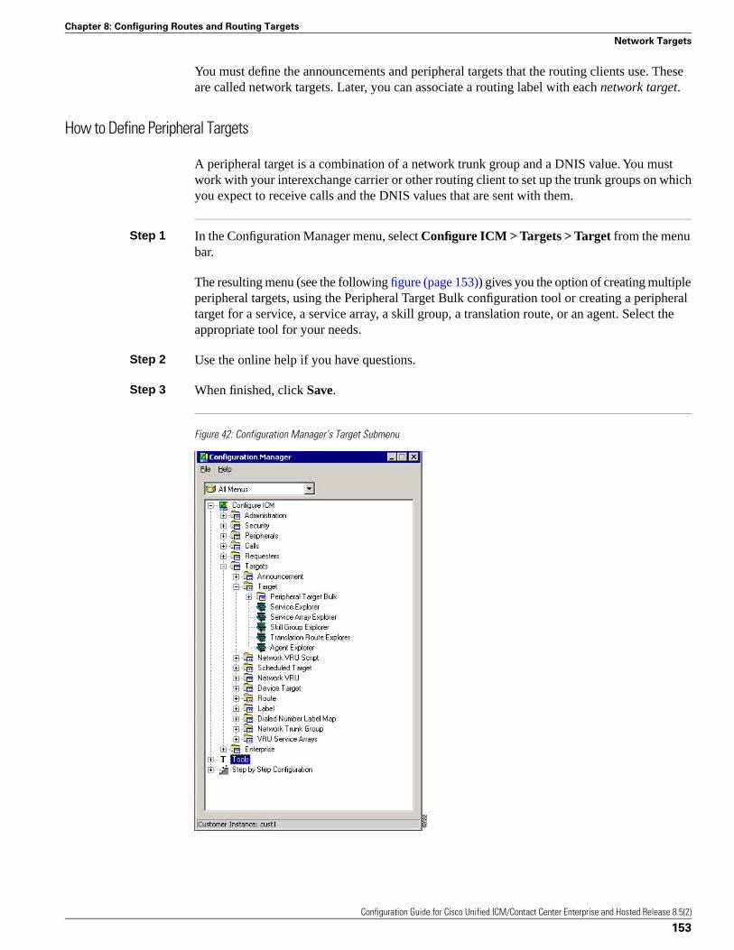
You must define the announcements and peripheral targets that the routing clients use. Theseare called network targets. Later, you can associate a routing label with each network target.
How to Define Peripheral Targets
A peripheral target is a combination of a network trunk group and a DNIS value. You mustwork with your interexchange carrier or other routing client to set up the trunk groups on whichyou expect to receive calls and the DNIS values that are sent with them.
Step 1 In the Configuration Manager menu, select Configure ICM > Targets > Target from the menubar.
The resulting menu (see the following figure (page 153)) gives you the option of creating multipleperipheral targets, using the Peripheral Target Bulk configuration tool or creating a peripheraltarget for a service, a service array, a skill group, a translation route, or an agent. Select theappropriate tool for your needs.
Step 2 Use the online help if you have questions.
Step 3 When finished, click Save.
Figure 42: Configuration Manager’s Target Submenu
Configuration Guide for Cisco Unified ICM/Contact Center Enterprise and Hosted Release 8.5(2)
153
Chapter 8: Configuring Routes and Routing Targets
Network Targets
Announcement Configuration Information
You must provide information about any announcements to which you want to route calls. Youmust work with the interexchange carrier or other routing client to set up announcements withinthe network and assign labels to them. You can then enter information about the labels into theUnified ICM system.
Note: If you have a Sprint routing client, the system software automatically configures anannouncement named NPA_Blocked_Recording.
How to Add Announcement Configuration Information
To add announcement configuration information, proceed along the following steps:
Step 1 In the Configuration Manager menu, select Tools > Explorer Tools > Announcement Explorer.The Announcement Explorer window appears.
Step 2 Click Retrieve. This enables the Add Announcement button.
Step 3 Click Add Announcement.
Step 4 In the Announcement tab, enter values for the following fields:
• Name. A unique name for the announcement.
• Description. Text identifying the announcement.
Note: You have the option of saving at this point and then adding the label information in thefollowing step.
Step 5 To associate a label with the announcement:
• In the tree list window select one from the UNASSIGNED group and drag it to theannouncement
In the tree list window select one from the UNASSIGNED group and drag it to theannouncement
• Select the announcement and click Add Label. Then in the Label tab, enter the appropriatefield information.
Note: A description of the Label tab fields and buttons is in the online help.
Step 6 Click Save to save the announcement configuration settings. The system software automaticallygenerates a unique Network Target ID value.
Configuration Guide for Cisco Unified ICM/Contact Center Enterprise and Hosted Release 8.5(2)
154
Chapter 8: Configuring Routes and Routing Targets
Announcement Configuration Information
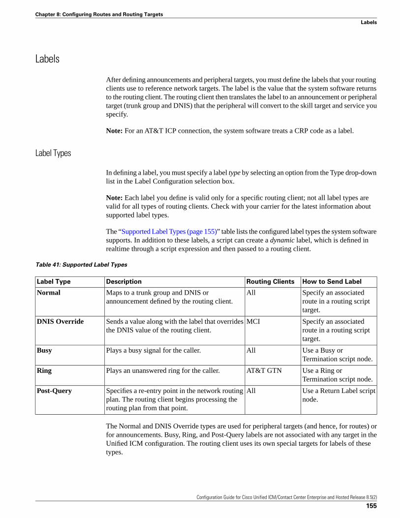
Labels
After defining announcements and peripheral targets, you must define the labels that your routingclients use to reference network targets. The label is the value that the system software returnsto the routing client. The routing client then translates the label to an announcement or peripheraltarget (trunk group and DNIS) that the peripheral will convert to the skill target and service youspecify.
Note: For an AT&T ICP connection, the system software treats a CRP code as a label.
Label Types
In defining a label, you must specify a label type by selecting an option from the Type drop-downlist in the Label Configuration selection box.
Note: Each label you define is valid only for a specific routing client; not all label types arevalid for all types of routing clients. Check with your carrier for the latest information aboutsupported label types.
The “Supported Label Types (page 155)” table lists the configured label types the system softwaresupports. In addition to these labels, a script can create a dynamic label, which is defined inrealtime through a script expression and then passed to a routing client.
Table 41: Supported Label Types
How to Send LabelRouting ClientsDescriptionLabel Type
Specify an associatedroute in a routing scripttarget.
AllMaps to a trunk group and DNIS orannouncement defined by the routing client.
Normal
Specify an associatedroute in a routing scripttarget.
MCISends a value along with the label that overridesthe DNIS value of the routing client.
DNIS Override
Use a Busy orTermination script node.
AllPlays a busy signal for the caller.Busy
Use a Ring orTermination script node.
AT&T GTNPlays an unanswered ring for the caller.Ring
Use a Return Label scriptnode.
AllSpecifies a re-entry point in the network routingplan. The routing client begins processing therouting plan from that point.
Post-Query
The Normal and DNIS Override types are used for peripheral targets (and hence, for routes) orfor announcements. Busy, Ring, and Post-Query labels are not associated with any target in theUnified ICM configuration. The routing client uses its own special targets for labels of thesetypes.
Configuration Guide for Cisco Unified ICM/Contact Center Enterprise and Hosted Release 8.5(2)
155
Chapter 8: Configuring Routes and Routing Targets
Labels
For more information about targets within scripts, see the Scripting and Media Routing Guidefor Cisco Unified ICM/Contact Center Enterprise & Hosted.
Special Sprint Labels
Sprint routing clients require two special labels to support the Busy feature and the NPA BlockedRecording feature:
• A Busy label named @Slow Busy.
• A Normal label named @NPA Blocked Recording. The target for this label must be theNPA_Blocked_Recording announcement.
When you use the NIC Explorer to set up a Sprint routing client, the system software createsthese labels automatically. (It also automatically creates the NPA_Blocked_Recordingannouncement, if necessary.)
The label names @Slow Busy and @NPA Blocked Recording are reserved for this specific use.You must not create any other labels with these names.
Creating Labels
To set up a label, you create configuration information and associate the label with a networktarget.
How to Create a Label
To create a label, follow these steps:
Step 1 In the Configuration Manager menu, select Configure ICM > Targets > Label.
Step 2 This displays the following menu options for configuring a label:
• Label Bulk
• Label List
• Service Explorer
• Service Array Explorer
• Skill Group Explorer
• Translation Route Explorer
• Agent Explorer
• Announcement Explorer
Configuration Guide for Cisco Unified ICM/Contact Center Enterprise and Hosted Release 8.5(2)
156
Chapter 8: Configuring Routes and Routing Targets
Labels
• Network VRU Explorer
Step 3 Select the tool you need:
• Use the Label Bulk tool to configure many labels at a time.
• Use the Label List tool to configure individual labels for any network targets.
• Use the preceding Explorer tools to configure labels for a specific network target (services,service arrays, skill groups, translation routes, agents, announcements, network VRUs).
Step 4 Enter values for the following fields. Use the online help if you have questions:
• Routing Client. (required) The enterprise name of the routing client that can receive thislabel.
• Label. (required)
The literal string of characters to be returned to the routing client.
• Label Type. (required)
The type of label. The valid types depend on the type of the routing client. For moreinformation, see the descriptions of label types in the “Supported Label Types (page 155)”table.
• Target type
(selection list) Indicates the type of the network target associated with the label: NetworkAnnouncement, PBX/ACD Peripheral (that is, a peripheral target), a device target, a scheduledtarget, or a network VRU.
Note: The Target type is a filter for the Network target field. The Target type selected is notretained unless a Network target is selected.
• Network target. (list and bulk tools only)
(selection list) Indicates the announcement, peripheral target, or scheduled target associatedwith the label.
• Customer. (list and bulk tools only)
The customer associated with the label.
• Description. Any other information you want about the label.
The Valid Label Targets (page 157) table lists which targets are valid for each label type.
Configuration Guide for Cisco Unified ICM/Contact Center Enterprise and Hosted Release 8.5(2)
157
Chapter 8: Configuring Routes and Routing Targets
Labels
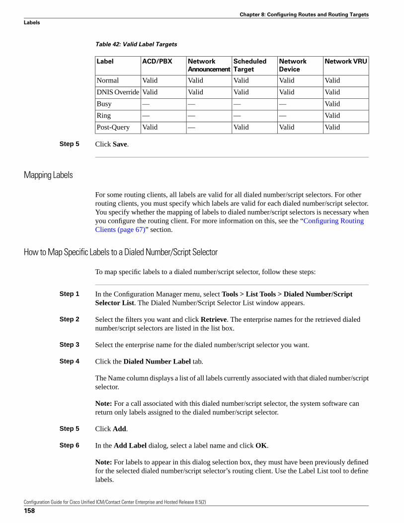
Table 42: Valid Label Targets
Network VRUNetwork
Device
Scheduled
Target
Network
Announcement
ACD/PBXLabel
ValidValidValidValidValidNormal
ValidValidValidValidValidDNIS Override
Valid————Busy
Valid————Ring
ValidValidValid—ValidPost-Query
Step 5 Click Save.
Mapping Labels
For some routing clients, all labels are valid for all dialed number/script selectors. For otherrouting clients, you must specify which labels are valid for each dialed number/script selector.You specify whether the mapping of labels to dialed number/script selectors is necessary whenyou configure the routing client. For more information on this, see the “Configuring RoutingClients (page 67)” section.
How to Map Specific Labels to a Dialed Number/Script Selector
To map specific labels to a dialed number/script selector, follow these steps:
Step 1 In the Configuration Manager menu, select Tools > List Tools > Dialed Number/ScriptSelector List. The Dialed Number/Script Selector List window appears.
Step 2 Select the filters you want and click Retrieve. The enterprise names for the retrieved dialednumber/script selectors are listed in the list box.
Step 3 Select the enterprise name for the dialed number/script selector you want.
Step 4 Click the Dialed Number Label tab.
The Name column displays a list of all labels currently associated with that dialed number/scriptselector.
Note: For a call associated with this dialed number/script selector, the system software canreturn only labels assigned to the dialed number/script selector.
Step 5 Click Add.
Step 6 In the Add Label dialog, select a label name and click OK.
Note: For labels to appear in this dialog selection box, they must have been previously definedfor the selected dialed number/script selector’s routing client. Use the Label List tool to definelabels.
Configuration Guide for Cisco Unified ICM/Contact Center Enterprise and Hosted Release 8.5(2)
158
Chapter 8: Configuring Routes and Routing Targets
Labels
Step 7 Click Save.
How to Set a Default Label for a Dialed Number/Script Selector
After you have defined labels, you can set a default label for each dialed number/script selector.If the system software fails to find a label by running the routing scripts for the call type, it usesthe default label for the dialed number/script selector.
You can use the Configuration Manager Dialed Number Bulk tool to configure many dialednumber/script selectors at a time or the Dialed Number/Script Selector List tool to configureone at a time. The following instructions show how to use the Dialed Number/Script SelectorList tool.
Step 1 In the Configuration Manager menu, select Tools > List Tools > Dialed Number/ScriptSelector List. The Dialed Number/Script Selector List window appears.
Step 2 Select the filters you want and click Retrieve. The enterprise names for the dialed number/scriptselector (or selectors) retrieved are listed in the list box.
Step 3 Select the dialed number/script selector you want and click the Attributes tab.
Step 4 In the Default label field, select the enterprise name of a label from the selection list. This listincludes all labels associated with the same routing client as the dialed number/script selector.
Step 5 After choosing the label, click Save.
Note: Within a routing script, you can explicitly invoke the default label for the current dialednumber/script selector by using a Termination node.
Service Arrays
Service arrays are closely tied to network trunk groups. Typically, you use service arrays incases where:
• You have similar peripheral services defined on multiple VRUs.
• VRUs all share the same network group.
By grouping the services of multiple VRUs into a service array, you can send calls to a singletarget (a service array) and let the network deliver the call to any one of the peripheral servicesthat make up the service array. For example, if several VRUs each support a Quotes service,you can define a Quotes service array for those services.
Configuration Guide for Cisco Unified ICM/Contact Center Enterprise and Hosted Release 8.5(2)
159
Chapter 8: Configuring Routes and Routing Targets
Service Arrays
How to Configure Service Arrays
To configure service arrays, proceed along the following steps:
Step 1 In the Configuration Manager menu, select Configure ICM > Targets > VRU Service Arrays> Service Array Explorer. The Service Array Explorer window appears.
Step 2 In the Select filter data box, select the appropriate filters and click Retrieve. This enables theAdd Service array button and displays a list of all currently defined service arrays associatedwith the selected PG.
Step 3 You can define a new service array or modify an existing one:
• To set up a new service array, click Add Service array.
Note: To create subsequent service arrays for the same PG, select the PG in the tree listwindow and then click Add Service array.
• To modify an existing service array, select it in the tree list window.
Step 4 In the Service Array tab for the selected service array, enter values for the following fields:
• Name. A unique name for the service array.
• Description. Additional information about the service array.
Step 5 Click the Members tab.
This tab lists the services that are current service array members of the selected PG.
• To add service members, click Add. Then in the Add Service Member window, select thename of a service from the list of available records and click OK. The Available records listcontains all the services connected to the peripherals associated with the selected PG.
• To remove a service member, select it in the list and click Remove.
Step 6 Add or modify a route associated with the service array:
• To add a route, select the service array in the tree list box, and click Add Route. Or in thetree list box, select a route from the UNASSIGNED group and drag it to the service array.Then in the Route tab, enter or modify the Name and Description.
• To modify the route, select it in the tree list box, and modify the Name and Description inthe Route tab.
Step 7 Add or modify one or more peripheral targets for the route:
• To add a peripheral target, select the route and click Add Peripheral target. Or in the treelist box, select a peripheral target from the UNASSIGNED group and drag it to the route.Then in the Peripheral target tab, enter the following:
Configuration Guide for Cisco Unified ICM/Contact Center Enterprise and Hosted Release 8.5(2)
160
Chapter 8: Configuring Routes and Routing Targets
Service Arrays

– DNIS. The DNIS value for the peripheral target. The routing client delivers this value tothe trunk group along with the call.
– Description. Any additional information about the DNIS value.
– Network trunk group. The group on which to deliver calls for the service array.
Step 8 To add or modify a label for the peripheral target:
• To add a label, select the peripheral target in the tree list box, and click Add Label. Or inthe tree list box, select a label from the UNASSIGNED group and drag it to the peripheraltarget. Then in the Label tab, enter or modify the following:
– Routing client. The enterprise name of the routing client that can receive this label.
– Label. The literal string of characters to be returned to the routing client.
– Label type. The type of label. The valid types depend on the type of the routing client.For more information, see the descriptions of label types in the “Supported Label Types(page 155)” table.
– Description. Any additional information about the label.
• To modify the label, select it in the tree list box, and modify the preceding fields in the Routetab.
Step 9 Click Save to save the changes to the database.
Step 10 Click Close to close the Service Array Explorer.
Application Wizard
The Application Wizard provides an alternate method for defining labels, peripheral targets,and routes and associating them with services at a peripheral.
Before starting the Application Wizard, you must have defined the routing client, peripheral,network trunk groups (and associated trunk groups), and services to be used. Within theApplication Wizard you can create dialed numbers, labels, peripheral targets, and routes.
Note: The Application Wizard does not allow you to associate routes and targets with skillgroups or agents. It allows you to target only services.
How to Use the Application Wizard
To use the Application Wizard, follow these steps:
Configuration Guide for Cisco Unified ICM/Contact Center Enterprise and Hosted Release 8.5(2)
161
Chapter 8: Configuring Routes and Routing Targets
Application Wizard
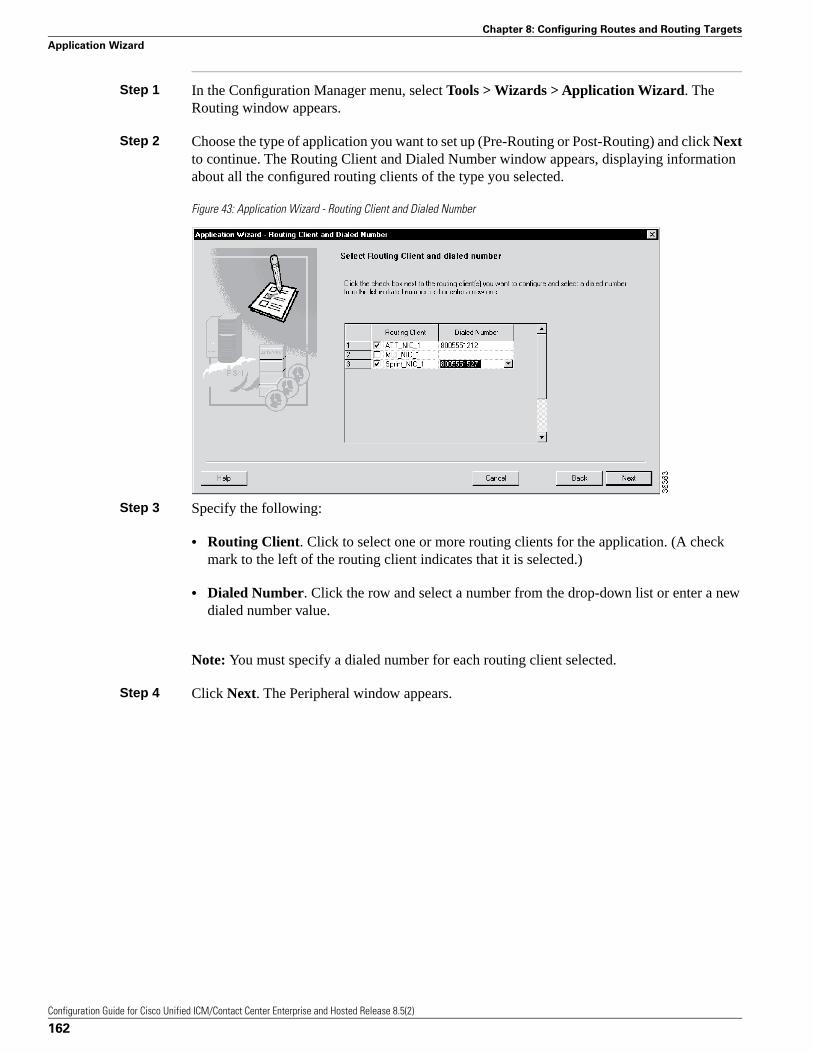
Step 1 In the Configuration Manager menu, select Tools > Wizards > Application Wizard. TheRouting window appears.
Step 2 Choose the type of application you want to set up (Pre-Routing or Post-Routing) and click Nextto continue. The Routing Client and Dialed Number window appears, displaying informationabout all the configured routing clients of the type you selected.
Figure 43: Application Wizard - Routing Client and Dialed Number
Step 3 Specify the following:
• Routing Client. Click to select one or more routing clients for the application. (A checkmark to the left of the routing client indicates that it is selected.)
• Dialed Number. Click the row and select a number from the drop-down list or enter a newdialed number value.
Note: You must specify a dialed number for each routing client selected.
Step 4 Click Next. The Peripheral window appears.
Configuration Guide for Cisco Unified ICM/Contact Center Enterprise and Hosted Release 8.5(2)
162
Chapter 8: Configuring Routes and Routing Targets
Application Wizard
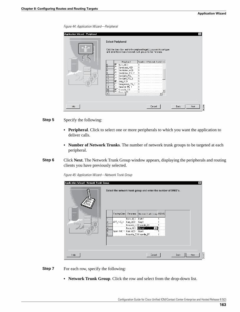
Figure 44: Application Wizard—Peripheral
Step 5 Specify the following:
• Peripheral. Click to select one or more peripherals to which you want the application todeliver calls.
• Number of Network Trunks. The number of network trunk groups to be targeted at eachperipheral.
Step 6 Click Next. The Network Trunk Group window appears, displaying the peripherals and routingclients you have previously selected.
Figure 45: Application Wizard—Network Trunk Group
Step 7 For each row, specify the following:
• Network Trunk Group. Click the row and select from the drop-down list.
Configuration Guide for Cisco Unified ICM/Contact Center Enterprise and Hosted Release 8.5(2)
163
Chapter 8: Configuring Routes and Routing Targets
Application Wizard
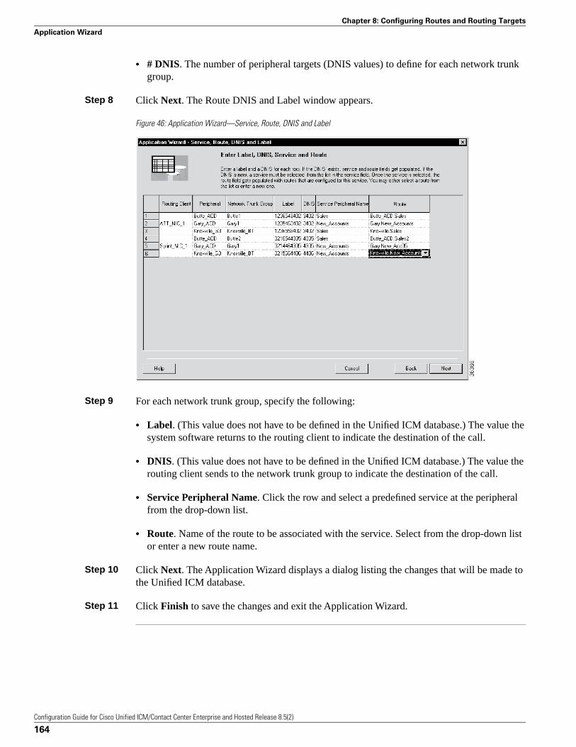
• # DNIS. The number of peripheral targets (DNIS values) to define for each network trunkgroup.
Step 8 Click Next. The Route DNIS and Label window appears.
Figure 46: Application Wizard—Service, Route, DNIS and Label
Step 9 For each network trunk group, specify the following:
• Label. (This value does not have to be defined in the Unified ICM database.) The value thesystem software returns to the routing client to indicate the destination of the call.
• DNIS. (This value does not have to be defined in the Unified ICM database.) The value therouting client sends to the network trunk group to indicate the destination of the call.
• Service Peripheral Name. Click the row and select a predefined service at the peripheralfrom the drop-down list.
• Route. Name of the route to be associated with the service. Select from the drop-down listor enter a new route name.
Step 10 Click Next. The Application Wizard displays a dialog listing the changes that will be made tothe Unified ICM database.
Step 11 Click Finish to save the changes and exit the Application Wizard.
Configuration Guide for Cisco Unified ICM/Contact Center Enterprise and Hosted Release 8.5(2)
164
Chapter 8: Configuring Routes and Routing Targets
Application Wizard
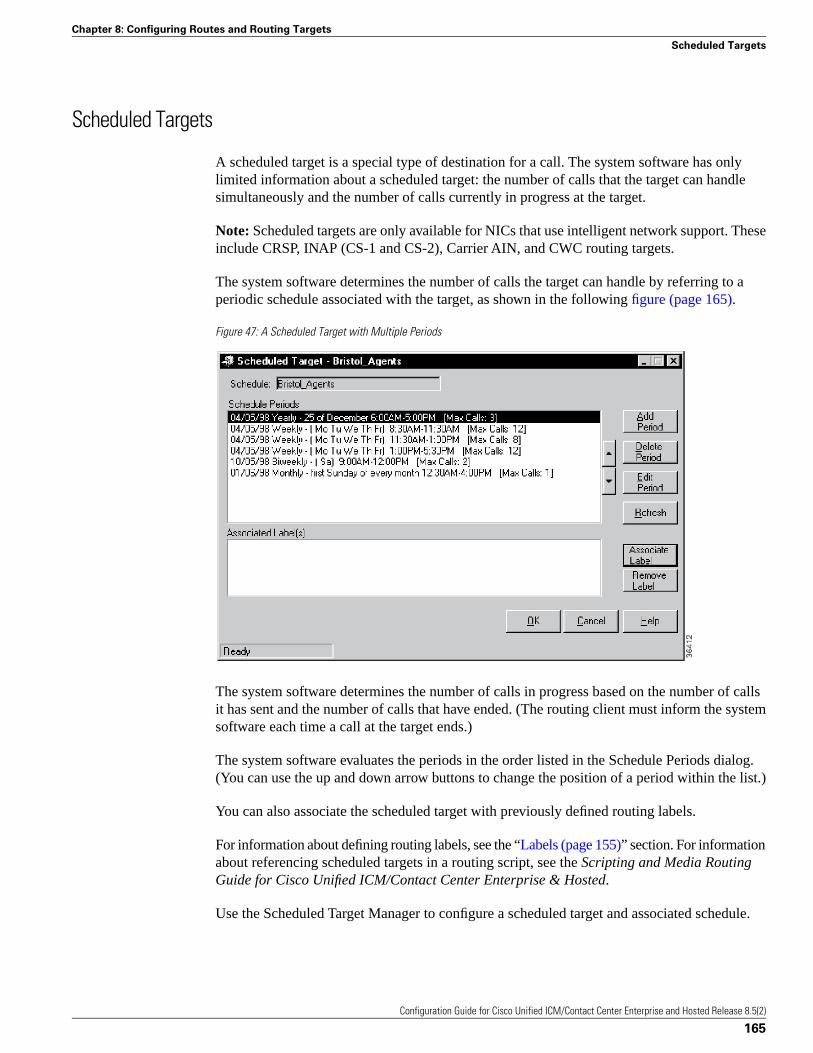
Scheduled Targets
A scheduled target is a special type of destination for a call. The system software has onlylimited information about a scheduled target: the number of calls that the target can handlesimultaneously and the number of calls currently in progress at the target.
Note: Scheduled targets are only available for NICs that use intelligent network support. Theseinclude CRSP, INAP (CS-1 and CS-2), Carrier AIN, and CWC routing targets.
The system software determines the number of calls the target can handle by referring to aperiodic schedule associated with the target, as shown in the following figure (page 165).
Figure 47: A Scheduled Target with Multiple Periods
The system software determines the number of calls in progress based on the number of callsit has sent and the number of calls that have ended. (The routing client must inform the systemsoftware each time a call at the target ends.)
The system software evaluates the periods in the order listed in the Schedule Periods dialog.(You can use the up and down arrow buttons to change the position of a period within the list.)
You can also associate the scheduled target with previously defined routing labels.
For information about defining routing labels, see the “Labels (page 155)” section. For informationabout referencing scheduled targets in a routing script, see the Scripting and Media RoutingGuide for Cisco Unified ICM/Contact Center Enterprise & Hosted.
Use the Scheduled Target Manager to configure a scheduled target and associated schedule.
Configuration Guide for Cisco Unified ICM/Contact Center Enterprise and Hosted Release 8.5(2)
165
Chapter 8: Configuring Routes and Routing Targets
Scheduled Targets
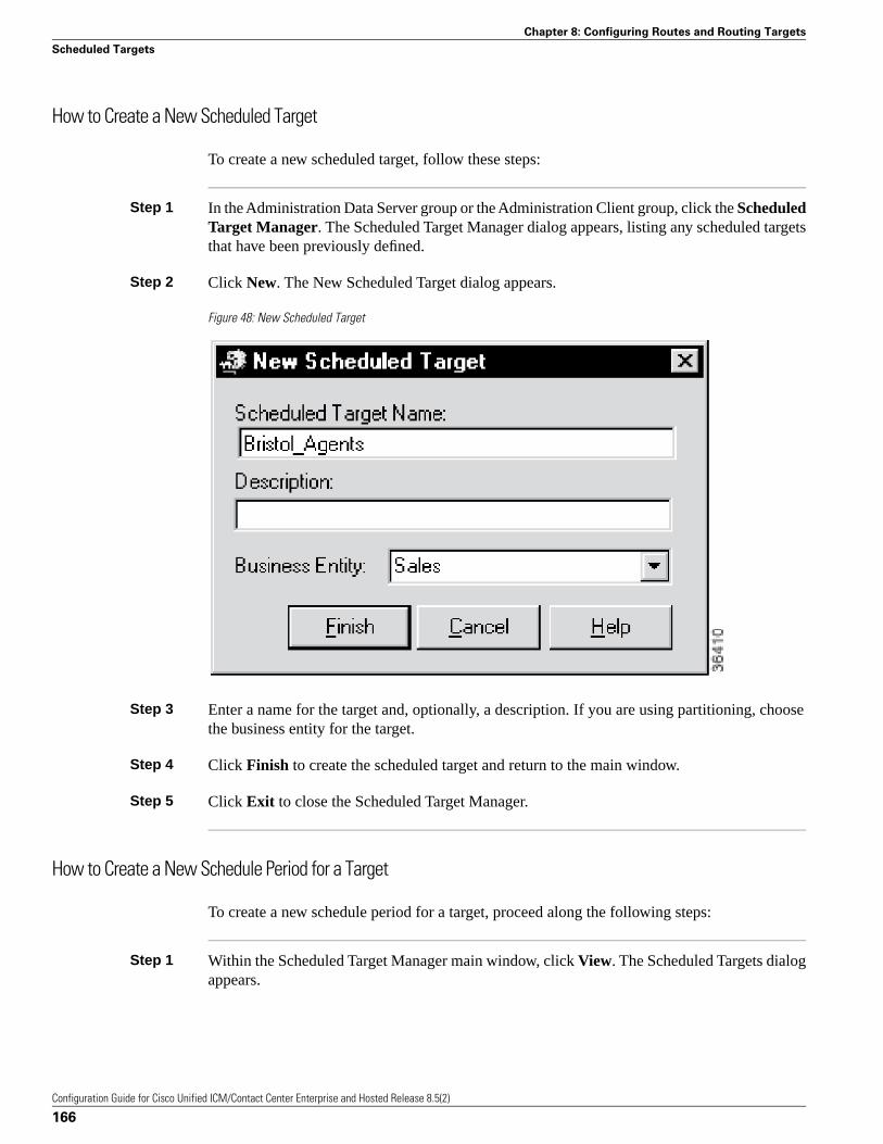
How to Create a New Scheduled Target
To create a new scheduled target, follow these steps:
Step 1 In the Administration Data Server group or the Administration Client group, click the ScheduledTarget Manager. The Scheduled Target Manager dialog appears, listing any scheduled targetsthat have been previously defined.
Step 2 Click New. The New Scheduled Target dialog appears.
Figure 48: New Scheduled Target
Step 3 Enter a name for the target and, optionally, a description. If you are using partitioning, choosethe business entity for the target.
Step 4 Click Finish to create the scheduled target and return to the main window.
Step 5 Click Exit to close the Scheduled Target Manager.
How to Create a New Schedule Period for a Target
To create a new schedule period for a target, proceed along the following steps:
Step 1 Within the Scheduled Target Manager main window, click View. The Scheduled Targets dialogappears.
Configuration Guide for Cisco Unified ICM/Contact Center Enterprise and Hosted Release 8.5(2)
166
Chapter 8: Configuring Routes and Routing Targets
Scheduled Targets
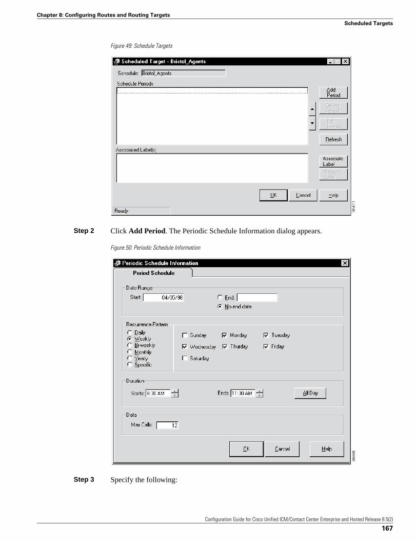
Figure 49: Schedule Targets
Step 2 Click Add Period. The Periodic Schedule Information dialog appears.
Figure 50: Periodic Schedule Information
Step 3 Specify the following:
Configuration Guide for Cisco Unified ICM/Contact Center Enterprise and Hosted Release 8.5(2)
167
Chapter 8: Configuring Routes and Routing Targets
Scheduled Targets
• Date Range. A starting date for the period and, optionally, an end date.
• Recurrence Pattern. Which days the schedule applies to.
Note: For details about the choices for the Recurrence Pattern fields, see the discussion ofscript scheduling in the Scripting and Media Routing Guide for Cisco Unified ICM/ContactCenter Enterprise & Hosted. The options for periodic schedules are the same as for scriptschedules.
• Duration. The time range for the schedule period.
• Data. The maximum number of calls in progress the target that can handle during the specifiedperiod.
Step 4 Click OK to save the period information and return to the Scheduled Target dialog.
Note: None of the periods you have added or changed are saved until you click the OK buttonfor the Scheduled Target.
Step 5 Click Exit to close the Scheduled Target Manager.
How to Associate Labels with a Scheduled Target
To associate labels with a scheduled target, follow these steps:
Step 1 Within the Scheduled Target Manager main window, click Associate Label. The AssociateLabel dialog appears, displaying a list of labels not currently associated with a target.
Step 2 Choose a label from the list and click OK to save the label and return to the Scheduled TargetManager dialog.
Step 3 Repeat Steps 1 and 2 to associate additional labels with the scheduled target.
Step 4 Click OK in the Scheduled Target dialog to save the changes you have made and return to theScheduled Target Manager main window.
Step 5 Click Exit to close the Scheduled Target Manager.
Translation Routes
A translation route is a special destination for a call that allows you to deliver other informationalong with the call. You do this by delivering the call first to the translation route. While therouting client is processing the call, the system software delivers the final destination for thecall to the Peripheral Gateway along with any other necessary information. The peripheral thenworks with the PG to reroute the call to the ultimate target and ensure that the appropriateinformation is also delivered.
Configuration Guide for Cisco Unified ICM/Contact Center Enterprise and Hosted Release 8.5(2)
168
Chapter 8: Configuring Routes and Routing Targets
Translation Routes
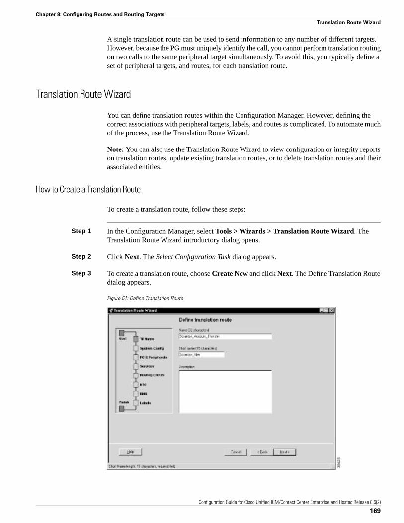
A single translation route can be used to send information to any number of different targets.However, because the PG must uniquely identify the call, you cannot perform translation routingon two calls to the same peripheral target simultaneously. To avoid this, you typically define aset of peripheral targets, and routes, for each translation route.
Translation Route Wizard
You can define translation routes within the Configuration Manager. However, defining thecorrect associations with peripheral targets, labels, and routes is complicated. To automate muchof the process, use the Translation Route Wizard.
Note: You can also use the Translation Route Wizard to view configuration or integrity reportson translation routes, update existing translation routes, or to delete translation routes and theirassociated entities.
How to Create a Translation Route
To create a translation route, follow these steps:
Step 1 In the Configuration Manager, select Tools > Wizards > Translation Route Wizard. TheTranslation Route Wizard introductory dialog opens.
Step 2 Click Next. The Select Configuration Task dialog appears.
Step 3 To create a translation route, choose Create New and click Next. The Define Translation Routedialog appears.
Figure 51: Define Translation Route
Configuration Guide for Cisco Unified ICM/Contact Center Enterprise and Hosted Release 8.5(2)
169
Chapter 8: Configuring Routes and Routing Targets
Translation Route Wizard
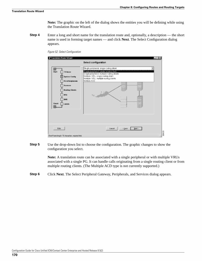
Note: The graphic on the left of the dialog shows the entities you will be defining while usingthe Translation Route Wizard.
Step 4 Enter a long and short name for the translation route and, optionally, a description — the shortname is used in forming target names — and click Next. The Select Configuration dialogappears.
Figure 52: Select Configuration
Step 5 Use the drop-down list to choose the configuration. The graphic changes to show theconfiguration you select.
Note: A translation route can be associated with a single peripheral or with multiple VRUsassociated with a single PG. It can handle calls originating from a single routing client or frommultiple routing clients. (The Multiple ACD type is not currently supported.)
Step 6 Click Next. The Select Peripheral Gateway, Peripherals, and Services dialog appears.
Configuration Guide for Cisco Unified ICM/Contact Center Enterprise and Hosted Release 8.5(2)
170
Chapter 8: Configuring Routes and Routing Targets
Translation Route Wizard
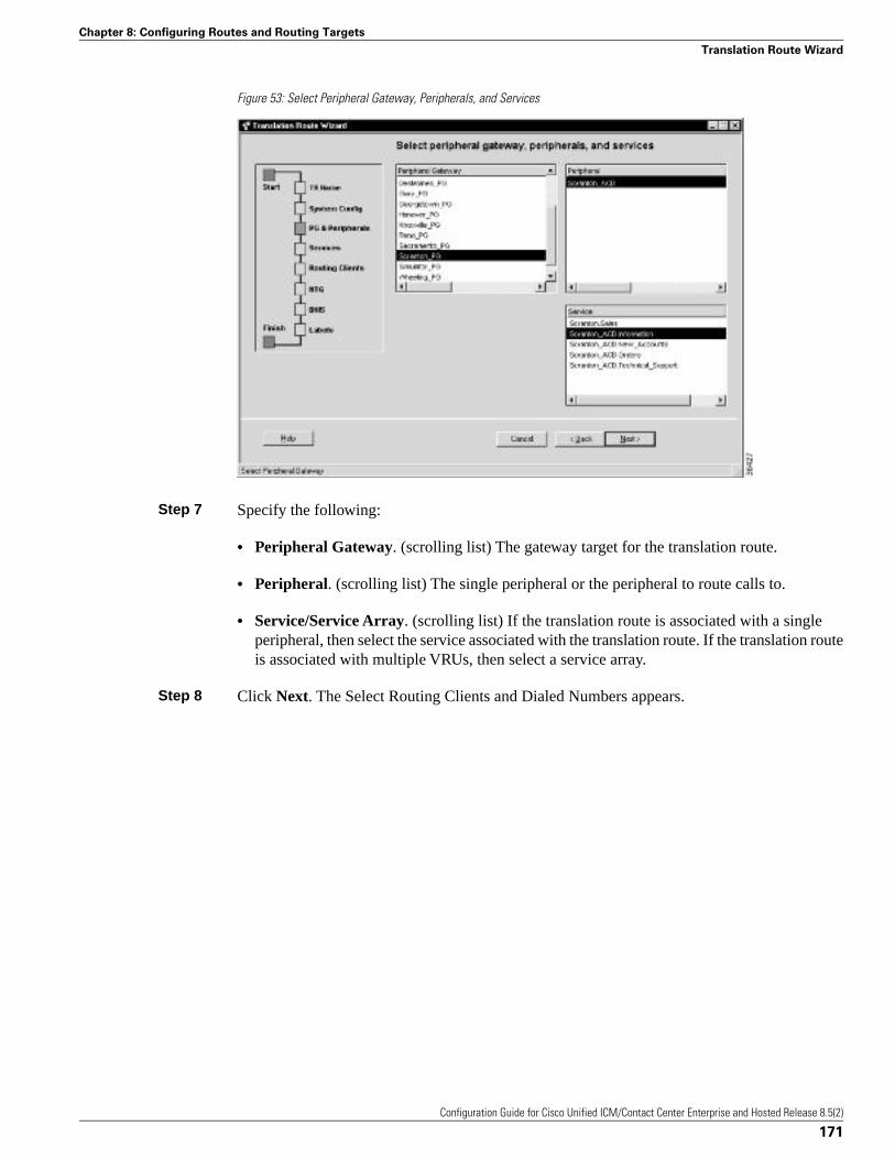
Figure 53: Select Peripheral Gateway, Peripherals, and Services
Step 7 Specify the following:
• Peripheral Gateway. (scrolling list) The gateway target for the translation route.
• Peripheral. (scrolling list) The single peripheral or the peripheral to route calls to.
• Service/Service Array. (scrolling list) If the translation route is associated with a singleperipheral, then select the service associated with the translation route. If the translation routeis associated with multiple VRUs, then select a service array.
Step 8 Click Next. The Select Routing Clients and Dialed Numbers appears.
Configuration Guide for Cisco Unified ICM/Contact Center Enterprise and Hosted Release 8.5(2)
171
Chapter 8: Configuring Routes and Routing Targets
Translation Route Wizard
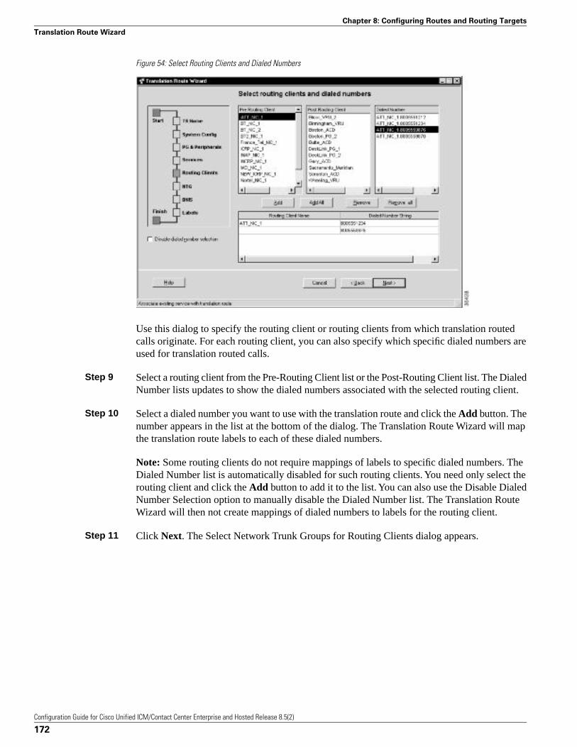
Figure 54: Select Routing Clients and Dialed Numbers
Use this dialog to specify the routing client or routing clients from which translation routedcalls originate. For each routing client, you can also specify which specific dialed numbers areused for translation routed calls.
Step 9 Select a routing client from the Pre-Routing Client list or the Post-Routing Client list. The DialedNumber lists updates to show the dialed numbers associated with the selected routing client.
Step 10 Select a dialed number you want to use with the translation route and click the Add button. Thenumber appears in the list at the bottom of the dialog. The Translation Route Wizard will mapthe translation route labels to each of these dialed numbers.
Note: Some routing clients do not require mappings of labels to specific dialed numbers. TheDialed Number list is automatically disabled for such routing clients. You need only select therouting client and click the Add button to add it to the list. You can also use the Disable DialedNumber Selection option to manually disable the Dialed Number list. The Translation RouteWizard will then not create mappings of dialed numbers to labels for the routing client.
Step 11 Click Next. The Select Network Trunk Groups for Routing Clients dialog appears.
Configuration Guide for Cisco Unified ICM/Contact Center Enterprise and Hosted Release 8.5(2)
172
Chapter 8: Configuring Routes and Routing Targets
Translation Route Wizard
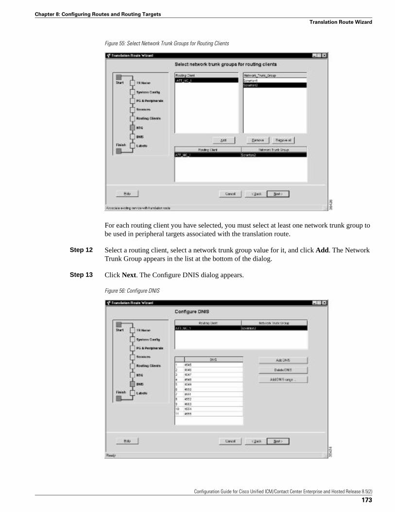
Figure 55: Select Network Trunk Groups for Routing Clients
For each routing client you have selected, you must select at least one network trunk group tobe used in peripheral targets associated with the translation route.
Step 12 Select a routing client, select a network trunk group value for it, and click Add. The NetworkTrunk Group appears in the list at the bottom of the dialog.
Step 13 Click Next. The Configure DNIS dialog appears.
Figure 56: Configure DNIS
Configuration Guide for Cisco Unified ICM/Contact Center Enterprise and Hosted Release 8.5(2)
173
Chapter 8: Configuring Routes and Routing Targets
Translation Route Wizard
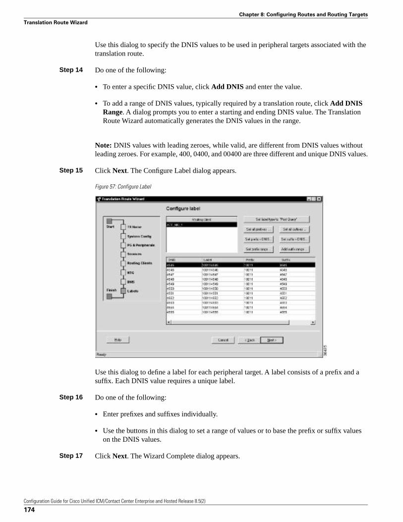
Use this dialog to specify the DNIS values to be used in peripheral targets associated with thetranslation route.
Step 14 Do one of the following:
• To enter a specific DNIS value, click Add DNIS and enter the value.
• To add a range of DNIS values, typically required by a translation route, click Add DNISRange. A dialog prompts you to enter a starting and ending DNIS value. The TranslationRoute Wizard automatically generates the DNIS values in the range.
Note: DNIS values with leading zeroes, while valid, are different from DNIS values withoutleading zeroes. For example, 400, 0400, and 00400 are three different and unique DNIS values.
Step 15 Click Next. The Configure Label dialog appears.
Figure 57: Configure Label
Use this dialog to define a label for each peripheral target. A label consists of a prefix and asuffix. Each DNIS value requires a unique label.
Step 16 Do one of the following:
• Enter prefixes and suffixes individually.
• Use the buttons in this dialog to set a range of values or to base the prefix or suffix valueson the DNIS values.
Step 17 Click Next. The Wizard Complete dialog appears.
Configuration Guide for Cisco Unified ICM/Contact Center Enterprise and Hosted Release 8.5(2)
174
Chapter 8: Configuring Routes and Routing Targets
Translation Route Wizard
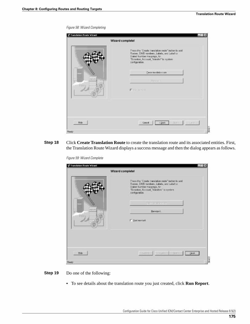
Figure 58: Wizard Completing
Step 18 Click Create Translation Route to create the translation route and its associated entities. First,the Translation Route Wizard displays a success message and then the dialog appears as follows.
Figure 59: Wizard Complete
Step 19 Do one of the following:
• To see details about the translation route you just created, click Run Report.
Configuration Guide for Cisco Unified ICM/Contact Center Enterprise and Hosted Release 8.5(2)
175
Chapter 8: Configuring Routes and Routing Targets
Translation Route Wizard

• To return to the beginning of the Translation Route Wizard and perform a new task, selectStart New Task and click Finish.
• To exit the Translation Route Wizard, click Finish.
Configuration Guide for Cisco Unified ICM/Contact Center Enterprise and Hosted Release 8.5(2)
176
Chapter 8: Configuring Routes and Routing Targets
Translation Route Wizard
Configuring Cisco Unified Intelligent ContactManagement Software for Integrated ApplicationsThese instructions provide information for installing and configuring Unified ICM Release 8.0software as part of a system integrated with the integrated applications.
Note: For detailed information about the Cisco Unified E-Mail Interaction Manager (UnifiedEIM) and Cisco Unified Web Interaction Manager (Unified WIM) applications, see the systemadministration documentation at http://www.cisco.com/en/US/products/ps7233/prod_maintenance_guides_list.html.
For additional information about the system software, see the Cisco web site (http://www.cisco.com) listing Unified ICM documentation: http://www.cisco.com/web/psa/products/index.html
For a high-level overview of integrating the applications with the system software, see the CiscoCustomer Contact Suite Implementation Map that is delivered with the system software.
Note: Important! While performing the tasks outlined in this chapter, be sure to note the systemsoftware configuration information, because you will need to enter this information whenconfiguring the integrated applications.
This chapter contains the following topics:
• Cisco Unified Intelligent Contact Management 8.0 Software Requirements, page 178• Configuring Cisco Unified Intelligent Contact Management Software for Integration, page
179• Application Object Filter, page 198
Configuration Guide for Cisco Unified ICM/Contact Center Enterprise and Hosted Release 8.5(2)
177
Chapter 9
Cisco Unified Intelligent Contact Management 8.0 Software Requirements
Note: Important! Do not install the system software and the integrated applications on thesame machine.
Before you begin configuring the system software for the integrated applications, you mustupgrade the system software.
For complete and current information about Software Requirements, see the Hardware & SystemSoftware Specification (Bill of Materials) for Cisco Unified ICM/Contact Center Enterprise &Hosted, Release 9.0(1). The Unified ICM bill of materials (BOM) is available at: http://www.cisco.com/univercd/cc/td/doc/product/icm/index.htm.
See the Upgrade Guide for Cisco Unified ICM/Contact Center Enterprise & Hosted for specificupgrade and installation requirements.
How to Install the Application Interface
Note: Important! You must install the application interface before beginning the Unified ICMconfiguration.
If you want your Administration & Data Server to be the point of contact for the integratedapplications configuration (to host the CMS Server), you need to perform this installation.
See the Installation Guide for Cisco Unified ICM/Contact Center Enterprise & Hosted fordetailed information about the Administration & Data Server setup.
Step 1 Run the Web Setup tool (accessed from the Unified CCE Tools folder).
Step 2 Select Component Management > Administration & Data Servers.
Step 3 Edit the Administration & Data Server on which the Distributor Service is running.
Step 4 On the Database and Options page, be sure to check Configuration Management Service(CMS) Node.
Step 5 Finish the installation process by completing the rest of the pages, then click Finish to saveyour edits.
After installing the application interface, you need to run the CMS Control tool on the installedAdministration & Data Server to set up, from the Unified ICM side, the connections that allowthe integrated applications to talk to that Administration & Data Server. You must also configurethe other end of the connection for each application .
To improve performance, if you are not using the console for debugging, keep the CMS nodeconsole minimized. If the console is not minimized, considerable CPU resources are tied updisplaying numerous messages from the system I/O.
Configuration Guide for Cisco Unified ICM/Contact Center Enterprise and Hosted Release 8.5(2)
178
Chapter 9: Configuring Cisco Unified Intelligent Contact Management Software for Integrated Applications
Cisco Unified Intelligent Contact Management 8.0 Software Requirements
See the “Application Connections (page 191)” section for more information about using theCMS Control tool to set up the connections between the system software and the integratedapplications.
Verify Pre-Integration Configuration
Verify the configuration by doing the following:
• Verify that all processes, including all Peripheral Interface Managers (PIMs) and CTI servers,are active (that is, all processes start, duplexed routers load the configuration and synchronize,and all PIMs and CTI servers are active).
• Verify that the MSSQL server has started. Submit sample calls through all routing clientsand all call types. Use the Call Tracer tool in the Script Editor to test router call handlingfunctionality.
Note: This test must be done before the Unified ICM upgrade and after the Unified ICM upgrade.Address failures before integration.
Configuring Cisco Unified Intelligent Contact Management Software for Integration
To configure the system software for the applications, you need to configure/install the following:
• Media routing domains for appropriate media classes within the system software
• Media routing peripheral gateways (PGs) and peripherals
• ECC (Expanded Call Context) variables
• Application instance or instances and define them in the system software
• Agents (you can create agents either in the system software or in the applications)
• Connections to the CMS server using the Application tab of the CMS Control tool in theAdministration Tools folder
• Configuration work on the integrated applications
• Skill group configuration using Script Editor
• Information to push to waiting Cisco Unified Interaction Manager callers
The following sections describe each of the preceding items, their configuration and installationinstructions, and indicate the configuration tool you need for each configuration. See the onlinehelp for a particular configuration tool if you have any questions.
Note: Before using the configuration tools to perform each configuration process, if you havemore than one Unified ICM instance you want to configure, open the Select Administration
Configuration Guide for Cisco Unified ICM/Contact Center Enterprise and Hosted Release 8.5(2)
179
Chapter 9: Configuring Cisco Unified Intelligent Contact Management Software for Integrated Applications
Configuring Cisco Unified Intelligent Contact Management Software for Integration
Instance tool in the Administration & Data Server or Administration Client and select the UnifiedICM instance with which you want to work.
Media Routing Domains
To create and then assign a media routing domain to a media class (physical media that thesystem software treats as a single concept), use the Configuration Manager Media RoutingDomain List tool.
The system software uses Media Routing Domains (MRDs) to organize how requests fromdifferent media are routed. An MRD is a collection of skill groups and services that are associatedwith a common communication medium. The system software uses an MRD to route a task toan agent who is associated with a skill group and a particular medium.
Before you can configure your application (for example, the Cisco Unified Interaction Manager)to use the system software as a routing engine, MRDs must be established in the system software.These MRDs have unique IDs across the enterprise. Then, on the application, you must enablethose Unified ICM Media Routing Domains that you need to use.
Note: Important! The MRD IDs must be created in the system software first, and then passedon to the person configuring the application, to perform a successful configuration. In CiscoUnified Interaction Manager you only need the MRD name, you do not need the MRD ID.
A media class describes the type of requests you want to set up for routing on the system software.
Note: Create the following media classes for Cisco Unified Interaction Manager:
• CIM_EIM
• CIM_WIM
• CIM_BC
The media class for voice already exists (Cisco_Voice).
How to Configure the Media Routing Domain
Step 1 Start the Configuration Manager and select Tools > List Tools > Media Routing Domain List.The Media Routing Domain List window is displayed. Click the Retrieve button and then theAdd button to display the Attributes tab.
Step 2 Enter the following information:
• Name. Enter the enterprise name of the MRD.
• Media Class. Use the drop-down list to select the media class for the integrated application.
• The MRDomainID is a required read-only field. (An ID number will be automatically createdwhen you save your entry.)
Configuration Guide for Cisco Unified ICM/Contact Center Enterprise and Hosted Release 8.5(2)
180
Chapter 9: Configuring Cisco Unified Intelligent Contact Management Software for Integrated Applications
Configuring Cisco Unified Intelligent Contact Management Software for Integration
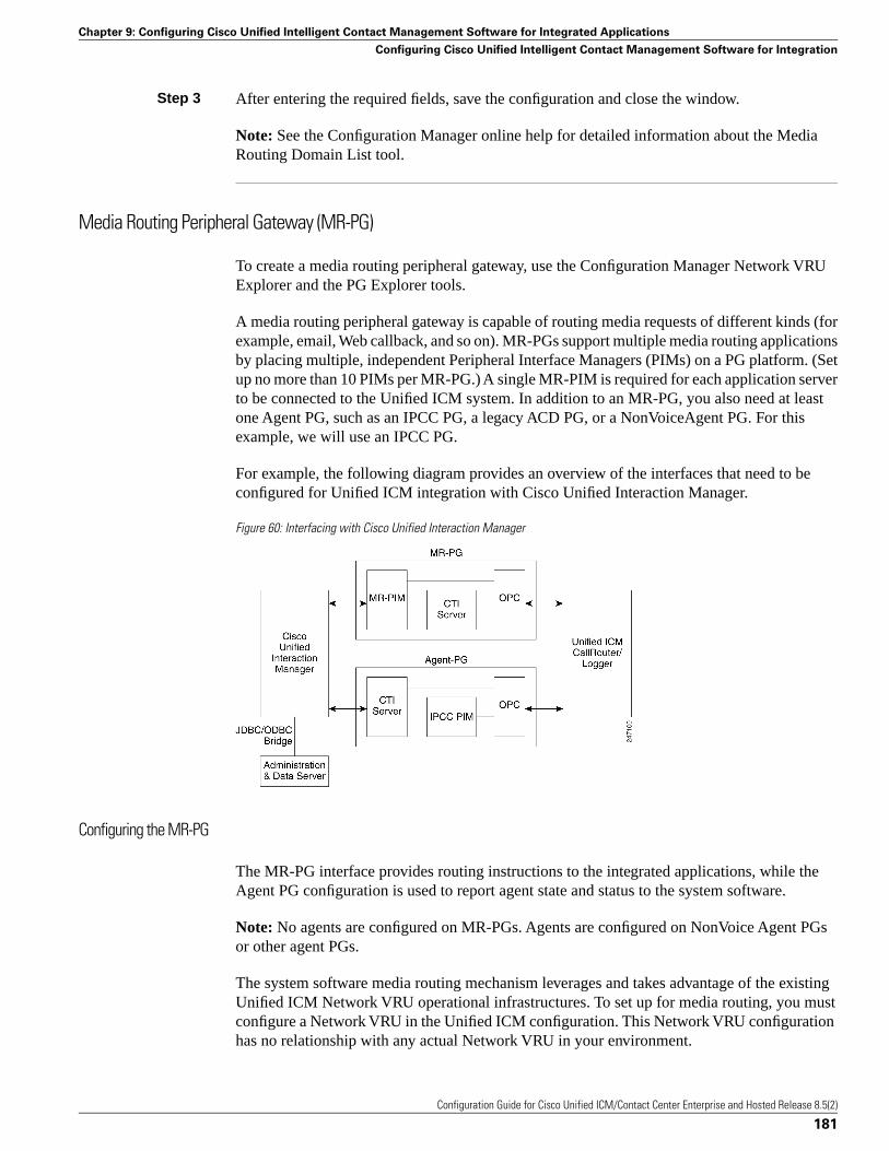
Step 3 After entering the required fields, save the configuration and close the window.
Note: See the Configuration Manager online help for detailed information about the MediaRouting Domain List tool.
Media Routing Peripheral Gateway (MR-PG)
To create a media routing peripheral gateway, use the Configuration Manager Network VRUExplorer and the PG Explorer tools.
A media routing peripheral gateway is capable of routing media requests of different kinds (forexample, email, Web callback, and so on). MR-PGs support multiple media routing applicationsby placing multiple, independent Peripheral Interface Managers (PIMs) on a PG platform. (Setup no more than 10 PIMs per MR-PG.) A single MR-PIM is required for each application serverto be connected to the Unified ICM system. In addition to an MR-PG, you also need at leastone Agent PG, such as an IPCC PG, a legacy ACD PG, or a NonVoiceAgent PG. For thisexample, we will use an IPCC PG.
For example, the following diagram provides an overview of the interfaces that need to beconfigured for Unified ICM integration with Cisco Unified Interaction Manager.
Figure 60: Interfacing with Cisco Unified Interaction Manager
Configuring the MR-PG
The MR-PG interface provides routing instructions to the integrated applications, while theAgent PG configuration is used to report agent state and status to the system software.
Note: No agents are configured on MR-PGs. Agents are configured on NonVoice Agent PGsor other agent PGs.
The system software media routing mechanism leverages and takes advantage of the existingUnified ICM Network VRU operational infrastructures. To set up for media routing, you mustconfigure a Network VRU in the Unified ICM configuration. This Network VRU configurationhas no relationship with any actual Network VRU in your environment.
Configuration Guide for Cisco Unified ICM/Contact Center Enterprise and Hosted Release 8.5(2)
181
Chapter 9: Configuring Cisco Unified Intelligent Contact Management Software for Integrated Applications
Configuring Cisco Unified Intelligent Contact Management Software for Integration
How to Configure the MR-PG
Step 1 Start the Configuration Manager. From the Configuration Manager menu, select ConfigureICM > Targets > Network VRU > Network VRU Explorer. The Network VRU Explorerwindow is displayed.
Step 2 Click the Retrieve button and then click the Add Network VRU button. The Network VRUdialog is displayed.
Step 3 Do the following:
• Enter a name for the Network VRU (for example, Cust_MR_VRU).
• Select Type 2 from Type drop-down list.
• Optionally, enter a description (that is, Media Routing).
• Save and close the window.
Step 4 From the Configuration Manager menu, select Configure ICM > Peripherals > Peripheral >PG Explorer. The PG Explorer window is displayed.
Step 5 Click the Retrieve and then click the Add PG button. The Logical controller dialog is displayed.
Step 6 Do the following:
• Enter a name for the PG (for example, Cust_MR_PG1).
• Select MR PG as the Client Type.
Step 7 In the tree section of the window, expand the tree and click the Add Peripheral button. ThePeripheral configuration dialog is displayed.
Step 8 Do the following:
• Select the Peripheral tab and check the Enable Post Routing box.
• Select the Advanced tab and select the previously created Network VRU from the drop-downlist.
• On the Routing Client tab, enter a routing client name (for example, Cust_MR_PG1_1.RC)and set the default timeouts to 2000, 1000, and 10, respectively.
• Save the configuration. After you save the configuration, the system assigns a LogicalController ID and a Physical Controller ID.
Note: Make a note of these values because you will need to provide them when you install theMR-PG.
Step 9 Close the window.
Configuration Guide for Cisco Unified ICM/Contact Center Enterprise and Hosted Release 8.5(2)
182
Chapter 9: Configuring Cisco Unified Intelligent Contact Management Software for Integrated Applications
Configuring Cisco Unified Intelligent Contact Management Software for Integration
Setting Up the MR-PG
Customer contact applications use the MediaRouting interface to request instructions from thesystem software when they receive a contact request from a customer using one of the mediums,such as email, web collaboration, or voice. When the system software receives a new task requestfrom the application, Unified ICM runs a pre-defined Unified ICM script to determine how tohandle the task.
Execution of the Unified ICM script, results in Unified ICM sending an instruction to theapplication to do one of the following:
• While the application is executing an application script that is stored on the application server,Unified ICM is looking for a best available agent that has the matching skill within theenterprise, and assigns this agent to this task.
• Handle the new task with a Unified ICM determined best available agent that has the matchingskill within the enterprise or a label the application utilizes to determine the best availableagent for the task.
Note: When choosing where to set up the MR-PG, be aware that you can only set up two PGsper server.
How to Set Up the MR-PG
To set up the MR-PG, follow these steps:
Step 1 Access the Peripheral Gateway Setup tool on the machine that you want to make an MR-PG.Add the customer if you have not already done so.
Step 2 Click Add in the Instance Components section and choose Peripheral Gateway from theUnified ICM Component Selection window. The Peripheral Gateway Properties window isdisplayed.
Step 3 Do the following:
• Choose Production Mode.
Note: The Auto Start at System Startup option ensures that the Peripheral Gateway can restartitself automatically if necessary. Set the Auto Start feature after installation is complete. Theserver may need to be rebooted a number of times during installation, and problems couldoccur if the node starts before hotfixes and databases are applied.
• Specify whether the PG is part of a duplexed pair.
• In the ID field, choose the PG device identifier as enabled in the CallRouter DeviceManagement Protocol (DMP) configuration dialog (part of setting up the CallRouter portion;enables the connection between the Router and the PG). Each logical PG must have a uniquedevice assignment at the CallRouter. (If a PG is duplexed, both physical machines use the
Configuration Guide for Cisco Unified ICM/Contact Center Enterprise and Hosted Release 8.5(2)
183
Chapter 9: Configuring Cisco Unified Intelligent Contact Management Software for Integrated Applications
Configuring Cisco Unified Intelligent Contact Management Software for Integration
same device assignment.) To add another logical PG, you must enable another PG devicefor the CallRouter.
• If the PG is duplexed, specify whether you are installing Side A or Side B. If the PG issimplexed, select Side A.
• Use the Client Type Selection section of the window to select MediaRouting and click theAdd button.
• Select the drive and language as appropriate and click the Next button.
Step 4 The Peripheral Gateway Component Properties window is displayed.
Enter the Logical Controller ID generated when you configured the PG with the PG Explorerin Step 8 of the “How to Configure the MR-PG (page 182)” section. Click the Add button andselect PIM 1 from the list.
Step 5 The MediaRouting Configuration box is displayed.
Step 6 Do the following:
• To put the PIM into service, check the Enabled option. This allows the PIM to communicatewith the peripheral when the Peripheral Gateway is running.
• Enter the peripheral name in the Peripheral name field. In most cases, you must use theenterprise name from the associated Peripheral record.
Note: When creating peripheral names, use short descriptive names and keep the length toa minimum.
• Enter the Peripheral ID from the Peripheral record.
• For Application Hostname (1), enter the host name or the IP address of the application servermachine (Cisco Unified Web Interaction Manager). If using the host name, the name mustbe in the host’s file.
• For Application Connection Port (1), enter the port number on the application server machinethat the PIM will use to communicate with the application.
• Leave Application Hostname (2) blank.
• Leave Application Connection Port (2) blank.
• For Heartbeat Interval (seconds), specify how often the PG will check its connection to theapplication server. (Use the default value.)
• For Reconnect Interval (seconds), specify how often the PG will try to re-establish a lostconnection to the application server. Use the default value
• Click OK.
Configuration Guide for Cisco Unified ICM/Contact Center Enterprise and Hosted Release 8.5(2)
184
Chapter 9: Configuring Cisco Unified Intelligent Contact Management Software for Integrated Applications
Configuring Cisco Unified Intelligent Contact Management Software for Integration
Step 7 From the Peripheral Gateway Component Properties window, click the Next button. The DeviceManagement Protocol Properties window is displayed. Enter the appropriate settings and clickthe Next button.
Step 8 The Peripheral Gateway Network Interfaces window is displayed. Enter the appropriate settingsand click the Next button.
Step 9 The Check Setup Information window is displayed. Verify the setup information and click theNext button. The system software sets up the PG.
Step 10 When the Setup Complete window is displayed, click the Finish button to exit from the setupprogram.
Configuring and Installing the IPCC PG
When agents and skill groups are created in the system software, they reside on a peripheral. Aperipheral can be associated with an IPCC, SoftACD, or Legacy ACD for agents doing workon the phone. If the agents on the peripheral will never be doing phone work, one or moreNonVoice peripherals can be used.
How to Configure the IPCC PG
To configure the IPCC PG, follow these steps:
Step 1 Start the Configuration Manager. From the Configuration Manager menu, select ConfigureICM > Peripherals > Peripheral > PG Explorer. The PG Explorer window is displayed.
Step 2 Click the Retrieve and then click the Add PG button. The Logical controller dialog is displayed.
Step 3 Do the following:
• Enter a name for the PG (for example, Cust_NVA_PG1).
• Select IPCC/SoftACD/EA as the Client Type.
• Enter the address for the Primary CTI server and the Secondary CTI server in the followingform:
<IP address of the CTI server>:<Client Connection Port Number>
that is, 192.168.1.101:42027
This entry is necessary for Cisco Unified E-Mail Interaction Manager to gather CTI connectiondata.
Step 4 In the tree section of the window, expand the tree and click on the peripheral. The Peripheralconfiguration dialog is displayed.
Step 5 Do the following:
Configuration Guide for Cisco Unified ICM/Contact Center Enterprise and Hosted Release 8.5(2)
185
Chapter 9: Configuring Cisco Unified Intelligent Contact Management Software for Integrated Applications
Configuring Cisco Unified Intelligent Contact Management Software for Integration
• Use the default name or change the name.
Note: This name is used in composite names which are limited to a 32 character length, forinstance, an agent enterprise name. Therefore, keep the name short.
• Unified CCE uses post routing, do not un-select the Enable Post Routing checkbox.
Step 6 Select the Advanced tab and click the Agent Reporting checkbox.
Step 7 Select the Routing Client tab and specify the routing client for post routing.
Note: This tab appears only if the Enable Post Routing checkbox is selected.
Step 8 Save the configuration. After you save the configuration, the system assigns a Logical ControllerID and a Physical Controller ID. Make a note of these values because you will need to providethem when you install the IPCC PG.
Step 9 Close the window.
How to Install the IPCC PG
To install the IPCC PG, follow these steps:
Step 1 Run the PG Setup tool (accessed from the Unified CCE Tools folder) on the machine that willbe the Agent PG. Add the customer if you have not already done so.
Step 2 Click Add in the Instance Components section and select Peripheral Gateway from the ICMComponent Selection window. The Peripheral Gateway Properties window is displayed.
Step 3 Do the following:
• Choose Production Mode.
Note: The Auto Start at System Startup option ensures that the Peripheral Gateway canrestart itself automatically if necessary. Set the Auto Start feature after installation is complete.The server may need to be rebooted a number of times during installation, and problemscould occur if the node starts before hotfixes and databases are applied.
• Specify whether the PG is part of a duplexed pair.
• In the ID field, choose the PG device identifier as enabled in the CallRouter DMPconfiguration dialog. Each logical PG must have a unique device assignment at the CallRouter.(If a PG is duplexed, both physical machines use the same device assignment.) To add anotherlogical PG, you must enable another PG device for the CallRouter.
• If the PG is duplexed, specify whether you are installing Side A or Side B. If the PG issimplexed, select Side A.
Configuration Guide for Cisco Unified ICM/Contact Center Enterprise and Hosted Release 8.5(2)
186
Chapter 9: Configuring Cisco Unified Intelligent Contact Management Software for Integrated Applications
Configuring Cisco Unified Intelligent Contact Management Software for Integration
• Use the Client Type Selection section of the window to select the IPCC/SoftACD/EA PGand click the Add button.
• Select the drive and language as appropriate and click the Next button.
Step 4 The Peripheral Gateway Component Properties window is displayed.
Enter the Logical Controller ID generated when you configured the Agent PG with the PGExplorer. Click the Add button.
Step 5 The IPCC/SoftACD/EA Configuration box is displayed.
Step 6 Do the following:
• To put the PIM into service, check the Enabled option. This allows the PIM to communicatewith the peripheral when the Peripheral Gateway is running.
• Enter the peripheral name in the Peripheral Name field. In most cases, you must use theenterprise name from the associated Peripheral record.
Note: When creating peripheral names, use short descriptive names and keep the length toa minimum.
• Enter the Peripheral ID from the Peripheral record.
• Specify the maximum length for an agent extension in the Agent Extension Length field.
• Click the IPCC button in the Telephony Server Protocol section.
• Enter the Unified CM host/IP that this peripheral will connect to in the Service field in theIPCC Parameters section.
• Specify a the User ID and User password created on the Unified CM you are connecting to.
Step 7 Click OK.
Installing CTI Server
You need to install a CTI Server for each Agent PG (the steps are basically the same as thosefor a Media Routing PG). Each PG uses CTI Server to provide the interface between theintegrated application and the system software.
Note:
• It is important that when you install a CTI Server, you pick the Custom Gateway (CG) thatcorresponds to the Agent PG that you just installed. For example, if you just installed aMR-PG as PG1 and an IPCC Agent PG as PG2; you must install the CTI Server for PG2 asCG2, not CG1.
• You do not need to install a CTI server on the Agent PG if one is already installed.
Configuration Guide for Cisco Unified ICM/Contact Center Enterprise and Hosted Release 8.5(2)
187
Chapter 9: Configuring Cisco Unified Intelligent Contact Management Software for Integrated Applications
Configuring Cisco Unified Intelligent Contact Management Software for Integration
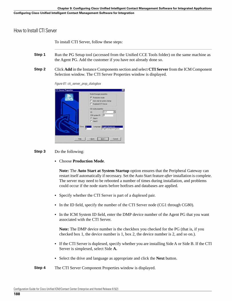
How to Install CTI Server
To install CTI Server, follow these steps:
Step 1 Run the PG Setup tool (accessed from the Unified CCE Tools folder) on the same machine asthe Agent PG. Add the customer if you have not already done so.
Step 2 Click Add in the Instance Components section and select CTI Server from the ICM ComponentSelection window. The CTI Server Properties window is displayed.
Figure 61: cti_server_prop_dialogbox
Step 3 Do the following:
• Choose Production Mode.
Note: The Auto Start at System Startup option ensures that the Peripheral Gateway canrestart itself automatically if necessary. Set the Auto Start feature after installation is complete.The server may need to be rebooted a number of times during installation, and problemscould occur if the node starts before hotfixes and databases are applied.
• Specify whether the CTI Server is part of a duplexed pair.
• In the ID field, specify the number of the CTI Server node (CG1 through CG80).
• In the ICM System ID field, enter the DMP device number of the Agent PG that you wantassociated with the CTI Server.
Note: The DMP device number is the checkbox you checked for the PG (that is, if youchecked box 1, the device number is 1, box 2, the device number is 2, and so on.).
• If the CTI Server is duplexed, specify whether you are installing Side A or Side B. If the CTIServer is simplexed, select Side A.
• Select the drive and language as appropriate and click the Next button.
Step 4 The CTI Server Component Properties window is displayed.
Configuration Guide for Cisco Unified ICM/Contact Center Enterprise and Hosted Release 8.5(2)
188
Chapter 9: Configuring Cisco Unified Intelligent Contact Management Software for Integrated Applications
Configuring Cisco Unified Intelligent Contact Management Software for Integration
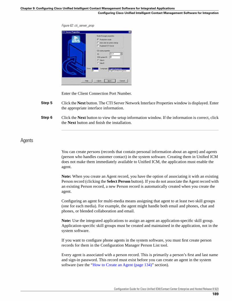
Figure 62: cti_server_prop
Enter the Client Connection Port Number.
Step 5 Click the Next button. The CTI Server Network Interface Properties window is displayed. Enterthe appropriate interface information.
Step 6 Click the Next button to view the setup information window. If the information is correct, clickthe Next button and finish the installation.
Agents
You can create persons (records that contain personal information about an agent) and agents(person who handles customer contact) in the system software. Creating them in Unified ICMdoes not make them immediately available to Unified ICM, the application must enable theagent.
Note: When you create an Agent record, you have the option of associating it with an existingPerson record (clicking the Select Person button). If you do not associate the Agent record withan existing Person record, a new Person record is automatically created when you create theagent.
Configuring an agent for multi-media means assigning that agent to at least two skill groups(one for each media). For example, the agent might handle both email and phones, chat andphones, or blended collaboration and email.
Note: Use the integrated applications to assign an agent an application-specific skill group.Application-specific skill groups must be created and maintained in the application, not in thesystem software.
If you want to configure phone agents in the system software, you must first create personrecords for them in the Configuration Manager Person List tool.
Every agent is associated with a person record. This is primarily a person’s first and last nameand sign-in password. This record must exist before you can create an agent in the systemsoftware (see the “How to Create an Agent (page 134)” section).
Configuration Guide for Cisco Unified ICM/Contact Center Enterprise and Hosted Release 8.5(2)
189
Chapter 9: Configuring Cisco Unified Intelligent Contact Management Software for Integrated Applications
Configuring Cisco Unified Intelligent Contact Management Software for Integration
The purpose of the person record is to allow, in a multi-channel contact center, one person tobe assigned as an agent on different peripherals, because the system software defines an agentas belonging to only one peripheral.
Note: The preceding is also true for non-integrated Unified ICM systems.
The second step in creating an agent in the system software is to use the Configuration ManagerAgent Explorer tool to create the agent. When you do so, the agent is associated with a person.
Non Voice Agents
A NonVoiceAgent PG/PIM is only intended for use at a site that does not have voice, but thatdoes want to use Unified ICM to do its multi-channel (Non Voice) contact routing. For such asite a Non Voice Agent PG is necessary, because every agent must be associated with aperipheral, and the site has no Agent peripheral other than the NonVoiceAgent PG. (A MediaRouting PG is also needed, but an MR-PG is not an Agent PG.)
At a site with voice, some agents may be NonVoice agents, that is, these agents will not make/taketelephone calls. Such agents are created on the IPCC or ACD PG for that site and indicated bya Peripheral Number beginning with the letters NV. You do not require a separateNonVoiceAgent PG for these agents.
Note: In this discussion “voice” means the making or taking of telephone calls, while NonVoiceimplies the inability to make or take such calls. This is to be distinguished from the meaningof Voice with regard to Media Classes. The Media Classes called Voice and BlendedCollaboration both involve “voice” in the current sense.
• If a NonVoice agent is created through the application, a peripheral-unique Peripheral Numberbeginning with the letters NV is automatically generated. If later you wish to change aNonVoice agent to a voice enabled agent, go to the Agent Explorer in Configuration Managerand change the agent’s Peripheral Number to the agent’s peripheral-unique voice PeripheralNumber (often the agent’s telephone number). Do not simply remove the letters NV fromthe beginning of the previously generated Peripheral Number. If the agent is created as avoice agent, a peripheral-unique peripheral number is assigned at creation.
• If you create a NonVoice agent through Configuration Manager, leave the Peripheral Numberfield blank when creating the agent. The system will then generate a peripheral-uniquePeripheral Number beginning with NV.
If you decide later that an existing NonVoice agent will be allowed to receive telephone calls,change the agent’s Peripheral Number to a voice Peripheral Number, using Agent Explorer, asindicated in the first bulleted item in the preceding list.
If you decide that an existing voice-enabled agent will become a NonVoice agent, delete thePeripheral Number as it appears in the Agent Explorer—thus blanking the field—and thencontinue as indicated in the second bulleted item from the preceding list.
Configuration Guide for Cisco Unified ICM/Contact Center Enterprise and Hosted Release 8.5(2)
190
Chapter 9: Configuring Cisco Unified Intelligent Contact Management Software for Integrated Applications
Configuring Cisco Unified Intelligent Contact Management Software for Integration
Application Instance
Important! Application instances must be configured before you configure the multi-mediaapplication.
Use the Configuration Manager Application Instance List tool to configure application instances,external to Unified ICM, to allow identification and access to the Configuration ManagementSystem (CMS). This enters an application ID and application key (password) that identifies theapplication. You need to enter the same information in the application.
Note: Important! Share the system software configuration information you noted during theprevious procedures with the person performing the integrated applications configuration.
How to Configure the Application Instance
To configure the application instance, follow these steps:
Step 1 Start the Configuration Manager and select Tools > List Tools > Application Instance List.The Application Instance List window is displayed. Click the Retrieve button and then the Addbutton to display the Attributes tab.
Step 2 Enter the following information:
• Name. The enterprise name for the application instance.
• Application key. This is the password that the integrated application will use to be identifiedby the system software. The password is restricted to the 7-bit printable ASCII characters(any of the 94 characters with the numeric values from 32 to 126). Control characters (forexample, 'tab') and international characters are not allowed. This means passwords cannotbe entered in a non-Western alphabet, such as Kanji.
• Application type. Available option is <Other>.
Note: Select <Other> when using Unified EIM and Unified WIM.
• Permission Level. Select the permission level from the drop-down list.
Step 3 After entering the required fields, save the configuration and close the window.
Note: See the Configuration Manager online help for detailed information about the ApplicationInstance List tool.
Application Connections
In order for the application to communicate with the Unified ICM system for configurationpurposes, a communications path between the system software and the application must beestablished.
Configuration Guide for Cisco Unified ICM/Contact Center Enterprise and Hosted Release 8.5(2)
191
Chapter 9: Configuring Cisco Unified Intelligent Contact Management Software for Integrated Applications
Configuring Cisco Unified Intelligent Contact Management Software for Integration
You can define the communications path from the system software (CMS Server) to theapplication using the Application tab in the CMS Control tool (resides on the Administration& Data Server in icm\bin directory). A similar user interface on the application side is used todefine the communications path from the application to the CMS Server.
Within the Application tab, the Application Connections table lists the current applicationconnections, where you can add, edit, and delete application connections.
Note: The Application link and Unified ICM Administration & Data Server link must matchon the application side.
How to Configure CMS Server Connections
To configure CMS Server connections, follow these steps:
Step 1 From the Start menu, select Run and enter C:\icm\bin\cmscontrol.exe to access CMSControl.
Step 2 Select the Application tab.
Step 3 Click Add. The Application Connection Details dialog is displayed.
Step 4 Enter the application connection properties:
• Administration & Data Server link. The Unified ICM RMI Driver connection end pointidentity.
• Administration & Data Server RMI Registry Port. The port number for the Unified ICMAdministration & Data Server RMI registry.
• Application link. The application RMI Driver connection end point identity.
• Application RMI registry port. The port number for the Application RMI registry.
• Application host name. The computer address where the application interface client resides.This name can be either an IP address or a name resolved by DNS or WINS.
Step 5 Click OK twice. This restarts the Cms_Jserver on the Administration & Data Server orAdministration Client.
Note: When you click OK the second time to save your changes and close the CMS Controlwindow, a message box may appear that states:
“The CmsJServer process is about to be cycled. Click OK to proceed or Cancel to quit.”
Click OK to proceed.
Note: See the application-specific instructions for specific field information. See the CMSControl tool online help for specific information about the field descriptions.
Configuration Guide for Cisco Unified ICM/Contact Center Enterprise and Hosted Release 8.5(2)
192
Chapter 9: Configuring Cisco Unified Intelligent Contact Management Software for Integrated Applications
Configuring Cisco Unified Intelligent Contact Management Software for Integration

Additional Configuration Setups
After configuring the system software, you need to perform the following configurations in theCisco Unified Interaction Manager application:
• Once you have configured the system software and Cisco Unified Interaction Manager, moreconfiguration must occur on the Cisco Media Blender server.
Note: See the Cisco Media Blender Administration Guide, Release 7.1, for details.
• Unified ICM and ACD queues:
If the Cisco Unified Interaction Manager will be used to send requests submitted to it to thesystem software, you must create one Unified ICM queue. When a request is submitted to aUnified ICM queue, the system software will route the request to the Cisco Unified InteractionManager and agent most appropriate to handle the request.
If you are using legacy ACDs for blended collaboration you must create ACD queues on theCisco Unified Interaction Manager. ACD queues are used to communicate with Cisco MediaBlender.
See the Cisco Unified Interaction Manager installation CD for documentation on performingthese configurations.
Using Application Gateways
An application gateway is an optional Unified ICM feature that allows you to invoke an externalapplication from within a script (using a Gateway node). You can pass data to the applicationand receive data in return, which you can then examine and use for routing decisions.
Before you can use these nodes in a script, you must first configure the gateways.
The application gateway requires connection information to communicate with the externalapplication. You perform this task using the Configuration Manager.
Configuring Application Gateways
You must configure an application gateway for each application you want to access from withinscripts.
Configuration information includes data such as:
• The type of application the gateway will interact with: a non-Unified ICM application or anapplication on another Unified ICM system
• The form of connection the gateway will use: duplex or simplex
Configuration Guide for Cisco Unified ICM/Contact Center Enterprise and Hosted Release 8.5(2)
193
Chapter 9: Configuring Cisco Unified Intelligent Contact Management Software for Integrated Applications
Configuring Cisco Unified Intelligent Contact Management Software for Integration

• A fault tolerance strategy for the gateway, described in the following “Application GatewayFault Tolerance Strategies (page 194)” table
Table 43: Application Gateway Fault Tolerance Strategies
DescriptionFault Tolerance Strategy
Each request is sent to both sides of the gateway.Duplicate Request
All requests are sent to only the A side of the gateway unless it fails. SideB is used only if side A is not available.
Alternate Request
The application gateway is not duplexed.None
Once you specify the configuration information, you can define the connection information forthe gateway, such as the network address of the port through which the system softwarecommunicates with the application.
If your Central Controller is duplexed, you can define separate connection information for eachside of the Central Controller. This allows each side to communicate with a local copy of theexternal application.
Note: For a remote Unified ICM, the address must be the same address specified for the ICRPNIC on the targeted system. (You may use the hostname in place of the address.) This addressvalue must be followed by a colon, an instance or customer number (denoting which UnifiedICM to access on the remote system), another colon, and a letter indicating which side of theNAM system prefers to use this connection. The preference letters are A (side A of the NAMprefers this connection), B (side B of the NAM prefers this connection), N (neither side of theNAM prefers this connection), or R (both sides of the NAM prefer this connection). For example,the address might be 199.97.123.45:1:A.
How to Configure an Application Gateway
To configure an application gateway, follow these steps:
Step 1 Within the Configuration Manager, select Tools > List Tools > Application Gateway List.The Application Gateway List window appears.
Step 2 To enable Add, click Retrieve.
Step 3 Click Add. The Attributes property tab appears.
Step 4 Complete the Attributes property tab.
Note: For additional information see the online Help.
Step 5 Click Save to create the application gateway.
Next, configure the connection information for the application gateway.
Configuration Guide for Cisco Unified ICM/Contact Center Enterprise and Hosted Release 8.5(2)
194
Chapter 9: Configuring Cisco Unified Intelligent Contact Management Software for Integrated Applications
Configuring Cisco Unified Intelligent Contact Management Software for Integration
How to Configure an Application Gateway Connection and Set the Default Connection Parameters
To configure an application gateway connection and set the default connection parameters,follow these steps:
Step 1 Within the Application Gateway List window, click Retrieve and select the desired ApplicationGateway.
Step 2 Complete the Connection property tab (or tabs).
Note: For additional information see the online Help.
Step 3 Click Save to apply your changes.
Skill Group Configuration with Script Editor
Universal Queue is the ability of the system software to route requests from voice, web, chat,and email channels from a single queue point directly to appropriately skilled agents. WithUniversal Queue, the system software treats requests from different media channels as a partof a single queue. Routing scripts send queued requests to agents based on business rulesregardless of the media channel. For example, the routing of asynchronous channels such asemail, and synchronous channels such as voice and chat, allows the system software to deliverthe right contact to the right resource the first time, regardless of the channel it came through.The Queue to Agent node allows the targeting of a task (the work performed by an agent) to ascript-specified agent.
The Queue to Agent node enables an agent to receive and operate on more than one task at atime. As a result, Universal Queue coordinates an agent’s ability to work on multiple tasks ofvarious media. It supports a simple control model where an agent’s ability to handle an additionaltask depends on what task that agent is currently handling. For this level of control, the systemsoftware must have exclusive access to task assignment.
Note: For Universal Queue to work, the agent must be assigned to skill groups that “ICM picksthe agent,” for which the system software does the routing.
The CallRouter has the ability to move tasks out of the present script execution and resubmitthem into the system as a new invocation.
Routing Script Configuration
Due to the introduction of a Media Routing Domain relationship, skill groups are mediumspecific. When an agent logs into the system software via a phone, or via Cisco UnifiedInteraction Manager, the agent actually logs into an MRD. This automatically logs the agentinto skill groups associated with that agent within that MRD. Then, as a task request for a specificMRD begins script execution, the CallRouter considers only the skill groups associated withthat specific MRD. This allows one script to be written to handle many MRDs.
Configuration Guide for Cisco Unified ICM/Contact Center Enterprise and Hosted Release 8.5(2)
195
Chapter 9: Configuring Cisco Unified Intelligent Contact Management Software for Integrated Applications
Configuring Cisco Unified Intelligent Contact Management Software for Integration

When upgrading from an earlier version of the system software, setup upgrades all existing skillgroup definitions to the Voice Media Routing Domain. (MRDs for chat, email, or blendedcollaboration media classes must be added using the Configuration Manager Media RoutingDomain List tool.)
The associated MRD applies to most related objects. Service member objects only map skillgroups to services of the same media routing domain.
Skill groups are created as follows:
• Skill groups for integrated email, chat, and blended collaboration are created, modified anddeleted using the system software.
• Skill groups for standalone email and chat are created, modified, and deleted using theapplication.
• Legacy ACD skill groups are configured on the ACD and on the system software.
Queue to Specific Agent
To assign a task to a specific agent, the CallRouter needs to do four things:
1. Pick an agent to receive the task.
2. Pick the MRD.
3. Pick a skill group from the list provided by the MRD selection.
4. Pick a route from the list provided by the skill group selection.
Using this style of Queue to Agent node, you select a specific agent at script design time.
In this case, where it is obvious who the agent is, the node property sheet displays a choice ofroutes for the peripheral that the agent is assigned to.
Note: Routes, agents, skill groups, and services are all associated with a peripheral.
How to Select Multiple Skill Groups and Routes for Different Media by Agent
To select multiple skill groups and routes for different media by agent, follow these steps:
Step 1 In Script Editor, open the appropriate script in Edit mode.
Step 2 Select the Queue to Agent node.
Step 3 Right-click and select Properties to open the Queue to Agent Properties dialog.
Step 4 Ensure the Queue to Agent type is set to Select using direct references. If not:
Configuration Guide for Cisco Unified ICM/Contact Center Enterprise and Hosted Release 8.5(2)
196
Chapter 9: Configuring Cisco Unified Intelligent Contact Management Software for Integrated Applications
Configuring Cisco Unified Intelligent Contact Management Software for Integration
1. Select Change to open the Queue Agent Type dialog.
2. Select Explicit agent references.
3. Click OK to return to the Queue to Agent Properties dialog.
Step 5 Select an agent from the drop-down list in the Agent column. This enables the rest of thecolumns.
Step 6 In the Domain column, select the appropriate MRD.
Step 7 In the appropriate column, select a skill group and a Route valid for the selected agent andMRD.
You can specify the agent multiple times, each with a different MRD selection.
Queue to Agent Expression
In this mode of the Queue to Agent node, the agent identity is determined by the queue to agentexpression at runtime.
Because the agent and MRD are not known until script execution time, you need some way ofselecting an appropriate skill group and route. To accomplish this, pick an enterprise skill group.Ensure the enterprise skill group includes appropriate skill groups to cover all MRD cases forthat agent. To select the route, use an enterprise route. Again, ensure that the enterprise routeincludes an appropriate collection of routes.
How to Select Multiple Skill Groups and Routes for Different Media by Agent Expression
To select multiple skill groups and routes for different media by agent expression, follow thesesteps:
Step 1 In Script Editor, open the appropriate script in Edit mode.
Step 2 Select the Queue to Agent node.
Step 3 Right-click and select Properties to open the Queue to Agent Properties dialog.
Step 4 Ensure the Queue to Agent type is set to Select using indirect references. If not:
1. Select Change to open the Queue Agent Type dialog.
2. Select Lookup agent references by expression.
3. Click OK to return to the Queue to Agent Properties dialog.
Step 5 Enter an agent expression (normally task.PreferredAgentID) into the Agent Expression column.Formula Editor is enabled when the Agent Expression column is selected.
Configuration Guide for Cisco Unified ICM/Contact Center Enterprise and Hosted Release 8.5(2)
197
Chapter 9: Configuring Cisco Unified Intelligent Contact Management Software for Integrated Applications
Configuring Cisco Unified Intelligent Contact Management Software for Integration
Step 6 In the appropriate column, select an appropriate Enterprise Skill Group and an EnterpriseRoute valid for the entered agent expression.
You can specify the agent expression multiple times, each with a different enterprise skill groupand enterprise route selection.
See the Scripting and Media Routing Guide for Cisco Unified ICM/Contact Center Enterprise& Hosted for more information about using Script Editor.
Pushing Information to Waiting Web Collaboration/Chat Users
On the Central Controller, you can create a Network VRU script list, which lists scripts set upto play to callers waiting for an agent.
With Unified ICM routing, you have the option of displaying information, such as advertisementsor informational URLs to a caller who is waiting to join a session with an agent. You can alsopopulate these ads or URLs so that they display caller information originating in the call form.This way, you can personalize ads or messages seen by the waiting caller.
You can set up a VRU script list to point to URLs or text messages to display on the browsersof callers waiting for a Collaboration agent. See the Cisco Unified Web and E-Mail InteractionManager System Administration Guide for detailed instructions on setting up this information.
Application Object Filter
The application object filter restricts access to application specific data that is not owned by therunning application. Application owned data includes skill groups, services, application paths,and routes. The application object filter is not applicable if there are no multimedia applications.
Access to the application object filter is restricted. You must use a super user password (casesensitive) to enable or disable the application object filter. This password is set as “password”during installation.
The application object filter is normally enabled, and prevents administrators from creating orediting application specific skill groups, services, application paths, or routes in the ConfigurationManager. Typically you want the application object filter to be enabled because creating orediting the preceding application specific data using Unified ICM could cause the applicationto become out of sync with Unified ICM. These items must be created and updated in theapplication requiring them, and not in the system software.
Disabling the application object filter allows administrators to create, delete, or edit applicationspecific skill groups, services, application paths, and routes from the Configuration Managertools. You might want to do this if, for example, an application is dead (you cannot access theapplication) and application specific data needs to be removed from the Unified ICM database.Another example of when you would want to disable the application object filter would be youneed clean up after removing an application.
Configuration Guide for Cisco Unified ICM/Contact Center Enterprise and Hosted Release 8.5(2)
198
Chapter 9: Configuring Cisco Unified Intelligent Contact Management Software for Integrated Applications
Application Object Filter
How to Disable an Application Object Filter
To disable an application object filter, follow these steps:
Step 1 Select Options > Application Object Filter.
Step 2 Enter the Password when prompted.
Step 3 Select Disable.
Step 4 The tool opens and the status line indicates the application object filter is disabled.
Note:
• Open tools are not affected by the change in the application object filter status. The statuschange only effects tools opened after the application object filter status is changed.
• Each time the Configuration Manager opens, the application object filter reverts to its defaultstatus – enabled.
Configuration Guide for Cisco Unified ICM/Contact Center Enterprise and Hosted Release 8.5(2)
199
Chapter 9: Configuring Cisco Unified Intelligent Contact Management Software for Integrated Applications
Application Object Filter

Configuration Guide for Cisco Unified ICM/Contact Center Enterprise and Hosted Release 8.5(2)
200
Chapter 9: Configuring Cisco Unified Intelligent Contact Management Software for Integrated Applications
Application Object Filter
Configuring Cisco Unified Intelligent ContactManagement VariablesThere are two types of Unified ICM variables you can configure:
• Expanded Call Context variables
• User variables
This chapter contains the following topics:
• ECC (Expanded Call Context) Variables, page 201• Configuring Expanded Call Context Variables, page 203• User Variables, page 205• How to Define a User Variable, page 206
ECC (Expanded Call Context) Variables
Expanded Call Context (ECC) variables are variables that you define and enable in theConfiguration Manager to store values associated with the call. You can specify the variablename and data type. The name must begin with the string user. These are in addition to thevariables the system software defines for each call (PeripheralVariable1 throughPeripheralVariable10, CallerEnteredDigits, CallingLineID, and so on).
An ECC variable name can be up to 33 bytes long (1-32 usable characters ). Use the followingnaming convention when creating an ECC variable:
user.<CompanyName>.<VariableDescription>
In this syntax:
• <CompanyName> is the name of your company
Configuration Guide for Cisco Unified ICM/Contact Center Enterprise and Hosted Release 8.5(2)
201
Chapter 10
• <VariableDescription> is a descriptive tag for the variable.
For example, you could use the following name for an ECC variable created for Cisco accountnumbers:
user.Cisco.AcctNum
Using this naming convention will prevent naming conflicts with third-party applications thatinterface with the system software.
Note: If your corporation is large, you may even want to break <VariableDescription> downto include the Business Unit, Division, or other organizational entity that exists in your company.
In addition:
• An ECC variable can be either a scalar variable or an array element, each with a maximumlength of 210 bytes.
• The maximum number of elements in an array can be 255.
• The maximum buffer size for each scalar variable = 5 + the maximum length of the variablewhere the 5 bytes includes 4 bytes to tag the variable and 1 byte for the null terminator.
• The maximum buffer size for each array = 5 + (1 + the maximum length of array element)* (the maximum number of elements in the array).
• There is a null terminator for each element, as well as a null terminator for the array as awhole.
• Because the total size of the buffer used to store the variables internally is 2000 bytes, thetotal sum of all the maximum buffer sizes for each variable and each array must be no greaterthan 2000.
For example, if you intended to use one scalar ECC variable with a maximum length of 100bytes, one scalar ECC variable with a maximum length of 80 bytes, and an ECC array witha maximum of 9 elements with each element having a maximum length of 200 bytes, thebuffer size would be: (5+100) + (5+80) + (5 + (1+200)*9) = 2004. As this buffer size is toolarge, the length of one of the scalar ECC variables or the length of the array ECC variablewould need to be adjusted.
ECC Variables for Cisco Blended Collaboration or Voice MRDs with Collaboration
ECC variables must be configured in the Configuration Manager Expanded Call Variable Listtool (for each integrated application) to route requests using the voice Media Routing Domain.
For Cisco Blended Collaboration or Voice MRDs with Collaboration, the ECC variables are:
• user.cisco.cmb
• user.cisco.cmb.callclass
Configuration Guide for Cisco Unified ICM/Contact Center Enterprise and Hosted Release 8.5(2)
202
Chapter 10: Configuring Cisco Unified Intelligent Contact Management Variables
ECC (Expanded Call Context) Variables
• user.cim.activity.id
• user.wim.customer.name
Note:
• Important! While their default size is 40 characters, use the Expanded Call Variable Listtool in the Configuration Manager to limit the user.cisco.cmb variable to 8 bytes and theuser.cisco.cmb.callclass variable to 10 bytes to prevent ECC space limitation issues.
• See the Configuration Manager online help for detailed information about the Expanded CallVariable List tool.
Configuring Expanded Call Context Variables
Expanded call context variable configuration consists of two steps:
• Setting the Expanded call context enabled option in the System Information dialog
• Defining the variable through the Expanded Call Variable List in the Configuration Manager
For Web Callback and Delayed Callback to work properly, an ECC variable (also known as anamed variable) must be defined. The Cisco CTI driver supports the use of ECC variables inaddition to the standard call variables associated with a call. Before an ECC variable can beused, it must be defined in the Unified ICM ECC variable database table.
Note: For more information, see the Database Schema Guide for Cisco Unified ICM/ContactCenter Enterprise & Hosted.
How to Set the Expanded Call Context Enabled Option
Step 1 Within the Configuration Manager, select Tools > Miscellaneous Tools > System Information.
The System Information window appears.
Step 2 Select Expanded call context enabled.
Note: For additional information see the online Help.
Step 3 Click Save to apply your changes.
How to Define an Expanded Call Context (ECC) Variable
Step 1 Within the Configuration Manager, select Tools > List Tools > Expanded Call Variable List.
The Expanded Call Variable List window appears.
Configuration Guide for Cisco Unified ICM/Contact Center Enterprise and Hosted Release 8.5(2)
203
Chapter 10: Configuring Cisco Unified Intelligent Contact Management Variables
Configuring Expanded Call Context Variables
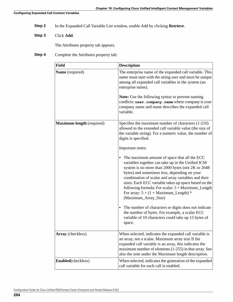
Step 2 In the Expanded Call Variable List window, enable Add by clicking Retrieve.
Step 3 Click Add.
The Attributes property tab appears.
Step 4 Complete the Attributes property tab:
DescriptionField
The enterprise name of the expanded call variable. Thisname must start with the string user and must be unique
Name (required)
among all expanded call variables in the system (anenterprise name).
Note: Use the following syntax to prevent namingconflicts: user.company.name where company is yourcompany name and name describes the expanded callvariable.
Specifies the maximum number of characters (1-210)allowed in the extended call variable value (the size of
Maximum length (required)
the variable string). For a numeric value, the number ofdigits is specified.
Important notes:
• The maximum amount of space that all the ECCvariables together can take up in the Unified ICMsystem is no more than 2000 bytes (not 2K or 2048bytes) and sometimes less, depending on yourcombination of scalar and array variables and theirsizes. Each ECC variable takes up space based on thefollowing formula: For scalar: 5 + Maximum_LengthFor array: 5 + (1 + Maximum_Length) *(Maximum_Array_Size)
• The number of characters or digits does not indicatethe number of bytes. For example, a scalar ECCvariable of 10 characters could take up 15 bytes ofspace.
When selected, indicates the expanded call variable isan array, not a scalar. Maximum array size If the
Array (checkbox)
expanded call variable is an array, this indicates themaximum number of elements (1-255) in that array. Seealso the note under the Maximum length description.
When selected, indicates the generation of the expandedcall variable for each call is enabled.
Enabled(checkbox)
Configuration Guide for Cisco Unified ICM/Contact Center Enterprise and Hosted Release 8.5(2)
204
Chapter 10: Configuring Cisco Unified Intelligent Contact Management Variables
Configuring Expanded Call Context Variables
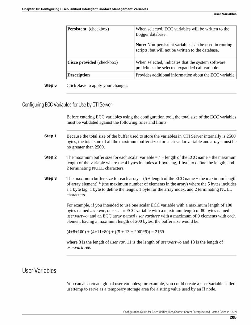
When selected, ECC variables will be written to theLogger database.
Persistent (checkbox)
Note: Non-persistent variables can be used in routingscripts, but will not be written to the database.
When selected, indicates that the system softwarepredefines the selected expanded call variable.
Cisco provided (checkbox)
Provides additional information about the ECC variable.Description
Step 5 Click Save to apply your changes.
Configuring ECC Variables for Use by CTI Server
Before entering ECC variables using the configuration tool, the total size of the ECC variablesmust be validated against the following rules and limits.
Step 1 Because the total size of the buffer used to store the variables in CTI Server internally is 2500bytes, the total sum of all the maximum buffer sizes for each scalar variable and arrays must beno greater than 2500.
Step 2 The maximum buffer size for each scalar variable = 4 + length of the ECC name + the maximumlength of the variable where the 4 bytes includes a 1 byte tag, 1 byte to define the length, and2 terminating NULL characters.
Step 3 The maximum buffer size for each array = (5 + length of the ECC name + the maximum lengthof array element) * (the maximum number of elements in the array) where the 5 bytes includesa 1 byte tag, 1 byte to define the length, 1 byte for the array index, and 2 terminating NULLcharacters.
For example, if you intended to use one scalar ECC variable with a maximum length of 100bytes named user.var, one scalar ECC variable with a maximum length of 80 bytes nameduser.vartwo, and an ECC array named user.varthree with a maximum of 9 elements with eachelement having a maximum length of 200 bytes, the buffer size would be:
(4+8+100) + (4+11+80) + ((5 + 13 + 200)*9)) = 2169
where 8 is the length of user.var, 11 is the length of user.vartwo and 13 is the length ofuser.varthree.
User Variables
You can also create global user variables; for example, you could create a user variable calledusertemp to serve as a temporary storage area for a string value used by an If node.
Configuration Guide for Cisco Unified ICM/Contact Center Enterprise and Hosted Release 8.5(2)
205
Chapter 10: Configuring Cisco Unified Intelligent Contact Management Variables
User Variables
Each user variable must:
• Have a name that begins with user.
Note: This name cannot contain the dot/period (.) character.
• Be associated with an object type, for example, Service. (This enables the system softwareto maintain an instance of that variable for each object of that type in the system.)
• Be identified as a persistent (retains value across CallRouter restarts) or non-persistent (doesnot retain value across CallRouter restarts) variable.
Note: A user variable can store a value up to 40 characters long.
After you have defined a variable, you can then use the Script Editor Formula Editor to accessthe variable and reference it in expressions, just as you would with a “built-in” variable
How to Define a User Variable
Step 1 Within the Configuration Manager, select Tools > List Tools > User Variable List.
The User Variable List window appears.
Step 2 In the User Variable List window, enable Add by clicking Retrieve.
Step 3 Click Add.
The Attributes property tab appears.
Step 4 Complete the Attributes property tab.
Note: The Variable name, Object type, and Data type fields are required. All other fields areoptional. For additional information see the online Help.
Step 5 Click Save to apply your changes.
Configuration Guide for Cisco Unified ICM/Contact Center Enterprise and Hosted Release 8.5(2)
206
Chapter 10: Configuring Cisco Unified Intelligent Contact Management Variables
User Variables
Network IVRs/VRUsThis chapter discusses the Network IVR/VRU feature that lets you divert a call to an interactivevoice response unit for additional processing.
It includes:
• An introduction to IVR/VRUs
• Information about how to configure IVR/VRUs
• A discussion on how to access IVR/VRUs in scripts
• Instructions on how to queue calls at IVR/VRUs
This chapter contains the following topics:
• Introducing Network IVRs/VRUs, page 207• VRU Configuration Tools, page 208• Configuring Network VRUs and VRU Scripts, page 215• Accessing VRUs in Cisco Unified Intelligent Contact Management Scripts, page 220• Queuing Calls at VRUs, page 221
Introducing Network IVRs/VRUs
Each routing client can have one or more associated Network Voice Response Units (VRUs).A VRU is a telecommunications computer, also called an Interactive Voice Response (IVR)unit, that responds to caller-entered touch-tone digits.
The routing client can be a public network interexchange carrier (IXC) intelligent network, ora private network peripheral, such as an Aspect or Avaya ACD.
Configuration Guide for Cisco Unified ICM/Contact Center Enterprise and Hosted Release 8.5(2)
207
Chapter 11
Note: Network VRUs are only available for intelligent public network IXCs, not all publicnetwork IXCs.
A Network VRU supports the system software service control interface. A routing script candivert a call to a Network VRU and instruct the VRU to perform specific processing before thesystem software determines the final destination for the call.
Preparation for using the VRU feature includes:
• Setting up Network VRU targets with the Configuration Manager
• Inserting VRU nodes in the routing script
This chapter describes how to perform these tasks.
Note: For the remainder of this chapter, the term VRU will be used exclusively to be consistentwith the on-screen prompts.
VRU Configuration Tools
Network VRU Explorer Tool
This tool allows a Network Applications Manager (NAM) to view, edit, or define networkVRUs, labels, and their associations. The system software can send a customer call to a networkVRU.
Note: The Network VRU Explorer is not available on a Limited (single Instance) Administration& Data Server.
To begin, select the filters you want and click Retrieve.
The changes you make in the Network VRU Explorer window are not applied to the databaseuntil you click Save.
Select Filter Data Box
Use the Select filter data box (see the “Accessing Database Records (page 32)” section inChapter 3 for additional information) to select and retrieve data from the database. Until youretrieve database data, no data is displayed.
Network VRU Label Tree
Hide/Show legend
This button toggles between Hide and Show. Click it to hide or show a diagram identifying allthe objects that can be displayed in the tree list box and showing their hierarchy.
Configuration Guide for Cisco Unified ICM/Contact Center Enterprise and Hosted Release 8.5(2)
208
Chapter 11: Network IVRs/VRUs
VRU Configuration Tools
Tree list box
The tree list box displays the names of the retrieved Network VRUs and, when expanded, thelabels associated with them.
When you select an item within the tree, details about that item appear in the tabbed propertyfields to the right of the tree list box.
Tree list box Properties
• Expanding (+)/contracting (-) the tree (+ and – buttons)
• Displaying option menu (right mouse button clicking)
• Making tree connections (drag and drop)
With the mouse, you can select an object and then move it to another part of the tree, as longas its object type belongs in that tree location.
For example, to move a route to another service, select it by clicking the left mouse button,and then move the mouse to that service. When that service becomes highlighted, lift yourfinger off the mouse. You could also use the Bulk Configuration tool to take the output of aswitch and create 20 or 30 labels. Then, using one of the Explorer tools, you could attachthese UNASSIGNED labels to an appropriate location.
• Symbols indicating object state (see the “Record Status Symbol Descriptions (page 37)”table in the “Common Bulk, List, and Explorer Tool Features” section.
• UNASSIGNED tree objects
A tree object is marked UNASSIGNED if it was made by another configuration tool and wasnot assigned (mapped) to a parent object.
For example, a label might not have been assigned to a peripheral target or a route might nothave been assigned to a service.
With the mouse, you can select an UNASSIGNED object and move it to a tree branch, aslong as it is an object that belongs in that tree location. Use the window legend to see whatobjects belong where.
When you move an UNASSIGNED object to an appropriate tree-branch location, you assignthat object to the object above it in the tree. Then the object is no longer unassigned. In thisway, for example, you might assign an unassigned label to a peripheral target.
Add
When you select an object in the tree, you can add another object of the same kind or an objectimmediately below it in the tree hierarchy. The Add buttons are enabled accordingly.
Add Network VRU
Click to add a network VRU to the database.
Configuration Guide for Cisco Unified ICM/Contact Center Enterprise and Hosted Release 8.5(2)
209
Chapter 11: Network IVRs/VRUs
VRU Configuration Tools
Add Label
Click to add a label to the selected network VRU.
Delete
Click to delete the selected object in the tree. This marks the selected object for deletion. Whenyou click Save, the object is deleted from the database.
If you select a network VRU, it and the labels associated with it are marked for deletion. If youselect a label, only the record for the label is marked for deletion.
Undelete
The Delete button toggles to Undelete when you select an object marked for deletion. Toundelete an object marked for deletion, select it and click Undelete.
Security
Visible only if you have partitioning. Enabled only if you have maintenance access to thedatabase record.
Click to apply security options to the selected tree object. For a description of the securityoptions, click.
ID status box
The label in the ID box at the bottom of the screen identifies the Unified ICM system on whichyou are working.
Network VRU Tab
Allows you to view (and define or edit, if you have maintenance access) the properties of theselected network VRU.
Table 44: Network VRU Tab Field Descriptions
DescriptionField
An enterprise name for the network VRU. This name must be unique forall network VRUs in the enterprise
Name (required)
(selection list) The type of network VRU. For additional information, seethe “Voice Response Unit (VRU) Types (page 215)” table.
Type (required)
Additional information about the network VRU.Description
Network VRU Banks Tab
This tab is enabled when you select a Type 9 in the Network VRU tab.
Configuration Guide for Cisco Unified ICM/Contact Center Enterprise and Hosted Release 8.5(2)
210
Chapter 11: Network IVRs/VRUs
VRU Configuration Tools
Table 45: Network VRU Banks Tab Button Descriptions
DescriptionButton
Displays a list of Trunk Groups that are on an IPCC System Peripheral.Add
Removes the added items from the list of Trunk Groups.Remove
Label tab
Allows you to view (and create, delete, or edit, if you have maintenance access) the propertiesof the selected label.
Table 46: Label Tab Field Descriptions
DescriptionField
Specify the Network Target for the Label to be associated with.Network VRU Bank
The enterprise name of the routing client associated with the label.Routing client (required)
The label value.Label (required)
(Drop-down list) The valid types depend on the type of routing client.Select one valid type for your routing client. Check with your carrier for
Label type (required)
the latest information about supported label types. Typical types areNormal, DNIS Override, Busy, Ring, and Post-Query.
The customer associated with the label.Customer (optional)
Additional information about the label.Description
Network VRU Script List Tool
This tool allows you to list the network VRU scripts currently defined in the Unified ICMdatabase, to define new ones, and to view, edit, or delete the records of existing ones.
Network VRU scripts are created by VRU engineers for VRUs. This List tool defines thesepreviously created scripts for the system software so it can interact with the scripts.
Note: The Network VRU Script List tool is not available on a Limited (single Instance)Administration & Data Server.
Select Filter Data Box
Use the Select filter data box (see the “Accessing Database Records (page 32)” section inChapter 3 for additional information) to select and retrieve data from the database. Until youretrieve database data, no data is displayed.
Network VRU Script List Box
Lists the network VRU scripts retrieved or created in the current editing session. The tabbedfields on the right side of the window display the properties of the selected network VRU script.
Configuration Guide for Cisco Unified ICM/Contact Center Enterprise and Hosted Release 8.5(2)
211
Chapter 11: Network IVRs/VRUs
VRU Configuration Tools
Attributes Tab
Allows you to view and (if you have maintenance access) to define, edit, or delete the attributesof the selected network VRU script.
Table 47: Attributes Tab Descriptions
DescriptionField
An enterprise name for the VRU script. This name must be unique for all VRUscripts in the system.
Name (required)
(selection list) The network VRU associated with the VRU script.Network VRU (required)
The number the VRU uses to identify the script.VRU script name (required)
The number of seconds Unified ICM will wait for a response after directing therouting client to run this script. If Unified ICM does not receive a response fromthe routing client within this time, it assumes the VRU script has failed.
Timeout (seconds) (required)
A string to be passed to the VRU when the script is invoked.Configuration param
(selection list) The customer associated with the VRU script, if any.Customer
Checked, indicates the script can be interrupted (for example, if an agent becomesavailable to handle the call).
Interruptible
Checked, indicates the script can make itself interruptible or non-interruptible.Overridable
Additional information about the VRU script.Description
Security Tab
Visible only on partitioned systems and enabled only on records for which you have maintenanceaccess.
VRU Currency List Tool
This tool allows you to list the VRU currencies currently defined in the Unified ICM database,to define new ones, and to view, edit, or delete the records of existing ones.
Select Filter Data Box
Use the Select filter data box (see the “Accessing Database Records (page 32)” section foradditional information) to select and retrieve data from the database. Until you retrieve databasedata, no data is displayed.
VRU Currency List Box
Lists the VRU currencies retrieved and or created in the current editing session. The tabbedfield on the right side of the window displays the name of the selected VRU currency.
Configuration Guide for Cisco Unified ICM/Contact Center Enterprise and Hosted Release 8.5(2)
212
Chapter 11: Network IVRs/VRUs
VRU Configuration Tools
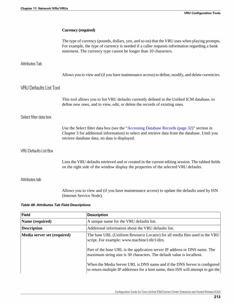
Currency (required)
The type of currency (pounds, dollars, yen, and so on) that the VRU uses when playing prompts.For example, the type of currency is needed if a caller requests information regarding a bankstatement. The currency type cannot be longer than 10 characters.
Attributes Tab
Allows you to view and (if you have maintenance access) to define, modify, and delete currencies.
VRU Defaults List Tool
This tool allows you to list VRU defaults currently defined in the Unified ICM database, todefine new ones, and to view, edit, or delete the records of existing ones.
Select filter data box
Use the Select filter data box (see the “Accessing Database Records (page 32)” section inChapter 3 for additional information) to select and retrieve data from the database. Until youretrieve database data, no data is displayed.
VRU Defaults List Box
Lists the VRU defaults retrieved and or created in the current editing session. The tabbed fieldson the right side of the window display the properties of the selected VRU defaults.
Attributes tab
Allows you to view and (if you have maintenance access) to update the defaults used by ISN(Internet Service Node).
Table 48: Attributes Tab Field Descriptions
DescriptionField
A unique name for the VRU defaults list.Name (required)
Additional information about the VRU defaults list.Description
The base URL (Uniform Resource Locator) for all media files used in the VRUscript. For example: www.machine1/dir1/dirs.
Media server set (required)
Part of the base URL is the application server IP address or DNS name. Themaximum string size is 30 characters. The default value is localhost.
When the Media Server URL is DNS name and if the DNS Server is configuredto return multiple IP addresses for a host name, then ISN will attempt to get the
Configuration Guide for Cisco Unified ICM/Contact Center Enterprise and Hosted Release 8.5(2)
213
Chapter 11: Network IVRs/VRUs
VRU Configuration Tools
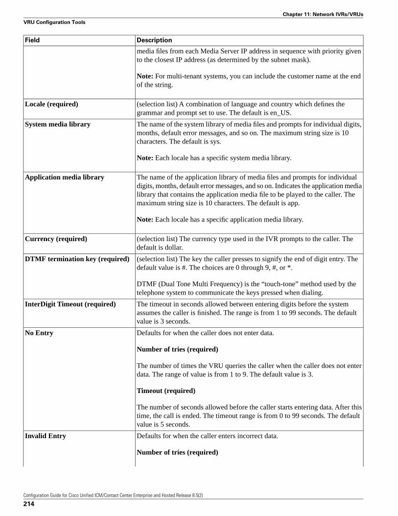
DescriptionField
media files from each Media Server IP address in sequence with priority givento the closest IP address (as determined by the subnet mask).
Note: For multi-tenant systems, you can include the customer name at the endof the string.
(selection list) A combination of language and country which defines thegrammar and prompt set to use. The default is en_US.
Locale (required)
The name of the system library of media files and prompts for individual digits,months, default error messages, and so on. The maximum string size is 10characters. The default is sys.
System media library
Note: Each locale has a specific system media library.
The name of the application library of media files and prompts for individualdigits, months, default error messages, and so on. Indicates the application media
Application media library
library that contains the application media file to be played to the caller. Themaximum string size is 10 characters. The default is app.
Note: Each locale has a specific application media library.
(selection list) The currency type used in the IVR prompts to the caller. Thedefault is dollar.
Currency (required)
(selection list) The key the caller presses to signify the end of digit entry. Thedefault value is #. The choices are 0 through 9, #, or *.
DTMF termination key (required)
DTMF (Dual Tone Multi Frequency) is the “touch-tone” method used by thetelephone system to communicate the keys pressed when dialing.
The timeout in seconds allowed between entering digits before the systemassumes the caller is finished. The range is from 1 to 99 seconds. The defaultvalue is 3 seconds.
InterDigit Timeout (required)
Defaults for when the caller does not enter data.No Entry
Number of tries (required)
The number of times the VRU queries the caller when the caller does not enterdata. The range of value is from 1 to 9. The default value is 3.
Timeout (required)
The number of seconds allowed before the caller starts entering data. After thistime, the call is ended. The timeout range is from 0 to 99 seconds. The defaultvalue is 5 seconds.
Defaults for when the caller enters incorrect data.Invalid Entry
Number of tries (required)
Configuration Guide for Cisco Unified ICM/Contact Center Enterprise and Hosted Release 8.5(2)
214
Chapter 11: Network IVRs/VRUs
VRU Configuration Tools
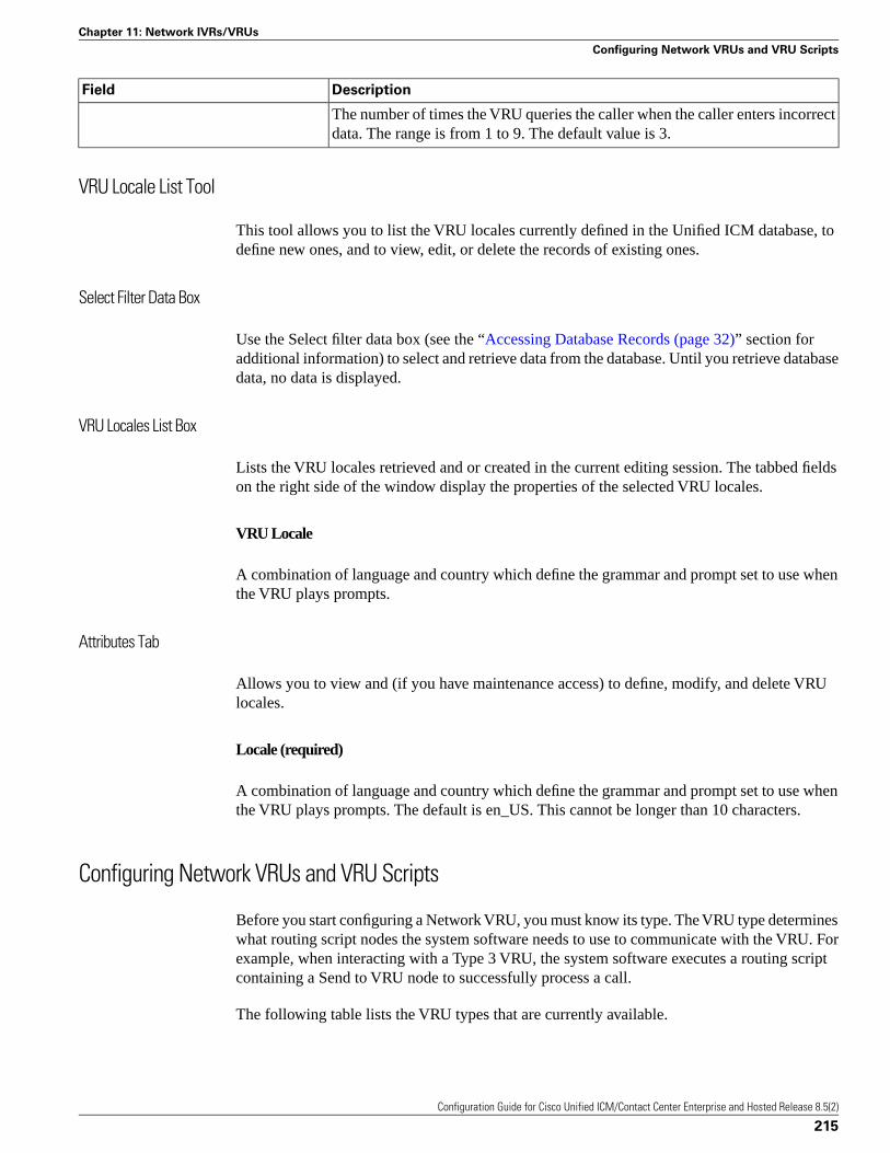
DescriptionField
The number of times the VRU queries the caller when the caller enters incorrectdata. The range is from 1 to 9. The default value is 3.
VRU Locale List Tool
This tool allows you to list the VRU locales currently defined in the Unified ICM database, todefine new ones, and to view, edit, or delete the records of existing ones.
Select Filter Data Box
Use the Select filter data box (see the “Accessing Database Records (page 32)” section foradditional information) to select and retrieve data from the database. Until you retrieve databasedata, no data is displayed.
VRU Locales List Box
Lists the VRU locales retrieved and or created in the current editing session. The tabbed fieldson the right side of the window display the properties of the selected VRU locales.
VRU Locale
A combination of language and country which define the grammar and prompt set to use whenthe VRU plays prompts.
Attributes Tab
Allows you to view and (if you have maintenance access) to define, modify, and delete VRUlocales.
Locale (required)
A combination of language and country which define the grammar and prompt set to use whenthe VRU plays prompts. The default is en_US. This cannot be longer than 10 characters.
Configuring Network VRUs and VRU Scripts
Before you start configuring a Network VRU, you must know its type. The VRU type determineswhat routing script nodes the system software needs to use to communicate with the VRU. Forexample, when interacting with a Type 3 VRU, the system software executes a routing scriptcontaining a Send to VRU node to successfully process a call.
The following table lists the VRU types that are currently available.
Configuration Guide for Cisco Unified ICM/Contact Center Enterprise and Hosted Release 8.5(2)
215
Chapter 11: Network IVRs/VRUs
Configuring Network VRUs and VRU Scripts
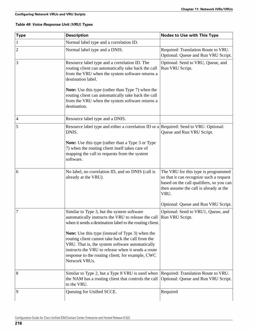
Table 49: Voice Response Unit (VRU) Types
Nodes to Use with This TypeDescriptionType
Normal label type and a correlation ID.1
Required: Translation Route to VRU.Optional: Queue and Run VRU Script.
Normal label type and a DNIS.2
Optional: Send to VRU, Queue, andRun VRU Script.
Resource label type and a correlation ID. Therouting client can automatically take back the call
3
from the VRU when the system software returns adestination label.
Note: Use this type (rather than Type 7) when therouting client can automatically take back the callfrom the VRU when the system software returns adestination.
Resource label type and a DNIS.4
Required: Send to VRU. Optional:Queue and Run VRU Script.
Resource label type and either a correlation ID or aDNIS.
5
Note: Use this type (rather than a Type 3 or Type7) when the routing client itself takes care ofmapping the call to requests from the systemsoftware.
The VRU for this type is programmedso that it can recognize such a request
No label, no correlation ID, and no DNIS (call isalready at the VRU).
6
based on the call qualifiers, so you canthen assume the call is already at theVRU.
Optional: Queue and Run VRU Script.
Optional: Send to VRU1, Queue, andRun VRU Script.
Similar to Type 3, but the system softwareautomatically instructs the VRU to release the callwhen it sends a destination label to the routing client.
7
Note: Use this type (instead of Type 3) when therouting client cannot take back the call from theVRU. That is, the system software automaticallyinstructs the VRU to release when it sends a routeresponse to the routing client; for example, CWCNetwork VRUs.
Required: Translation Route to VRU.Optional: Queue and Run VRU Script.
Similar to Type 2, but a Type 8 VRU is used whenthe NAM has a routing client that controls the callto the VRU.
8
RequiredQueuing for Unified SCCE.9
Configuration Guide for Cisco Unified ICM/Contact Center Enterprise and Hosted Release 8.5(2)
216
Chapter 11: Network IVRs/VRUs
Configuring Network VRUs and VRU Scripts
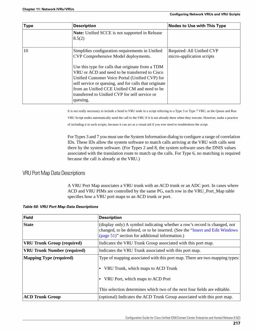
Nodes to Use with This TypeDescriptionType
Note: Unified SCCE is not supported in Release8.5(2)
Required: All Unified CVPmicro-application scripts
Simplifies configuration requirements in UnifiedCVP Comprehensive Model deployments.
10
Use this type for calls that originate from a TDMVRU or ACD and need to be transferred to CiscoUnified Customer Voice Portal (Unified CVP) forself service or queuing, and for calls that originatefrom an Unified CCE Unified CM and need to betransferred to Unified CVP for self service orqueuing.
It is not really necessary to include a Send to VRU node in a script referring to a Type 3 or Type 7 VRU, as the Queue and Run
VRU Script nodes automatically send the call to the VRU if it is not already there when they execute. However, make a practice
of including it in such scripts, because it can act as a visual aid if you ever need to troubleshoot the script.
For Types 3 and 7 you must use the System Information dialog to configure a range of correlationIDs. These IDs allow the system software to match calls arriving at the VRU with calls sentthere by the system software. (For Types 2 and 8, the system software uses the DNIS valuesassociated with the translation route to match up the calls. For Type 6, no matching is requiredbecause the call is already at the VRU.)
VRU Port Map Data Descriptions
A VRU Port Map associates a VRU trunk with an ACD trunk or an ADC port. In cases whereACD and VRU PIMs are controlled by the same PG, each row in the VRU_Port_Map tablespecifies how a VRU port maps to an ACD trunk or port.
Table 50: VRU Port Map Data Descriptions
DescriptionField
(display only) A symbol indicating whether a row’s record is changed, notchanged, to be deleted, or to be inserted. (See the “Insert and Edit Windows(page 51)” section for additional information.)
State
Indicates the VRU Trunk Group associated with this port map.VRU Trunk Group (required)
Indicates the VRU Trunk associated with this port map.VRU Trunk Number (required)
Type of mapping associated with this port map. There are two mapping types:Mapping Type (required)
• VRU Trunk, which maps to ACD Trunk
• VRU Port, which maps to ACD Port
This selection determines which two of the next four fields are editable.
(optional) Indicates the ACD Trunk Group associated with this port map.ACD Trunk Group
Configuration Guide for Cisco Unified ICM/Contact Center Enterprise and Hosted Release 8.5(2)
217
Chapter 11: Network IVRs/VRUs
Configuring Network VRUs and VRU Scripts
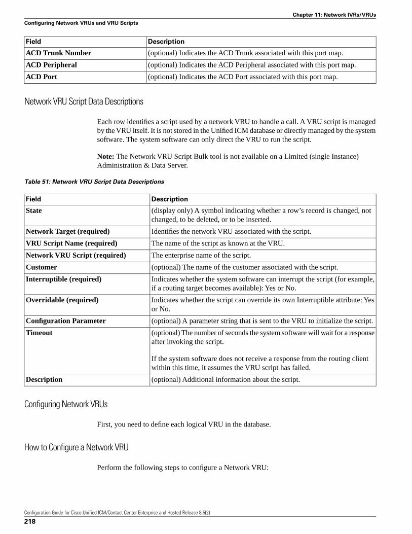
DescriptionField
(optional) Indicates the ACD Trunk associated with this port map.ACD Trunk Number
(optional) Indicates the ACD Peripheral associated with this port map.ACD Peripheral
(optional) Indicates the ACD Port associated with this port map.ACD Port
Network VRU Script Data Descriptions
Each row identifies a script used by a network VRU to handle a call. A VRU script is managedby the VRU itself. It is not stored in the Unified ICM database or directly managed by the systemsoftware. The system software can only direct the VRU to run the script.
Note: The Network VRU Script Bulk tool is not available on a Limited (single Instance)Administration & Data Server.
Table 51: Network VRU Script Data Descriptions
DescriptionField
(display only) A symbol indicating whether a row’s record is changed, notchanged, to be deleted, or to be inserted.
State
Identifies the network VRU associated with the script.Network Target (required)
The name of the script as known at the VRU.VRU Script Name (required)
The enterprise name of the script.Network VRU Script (required)
(optional) The name of the customer associated with the script.Customer
Indicates whether the system software can interrupt the script (for example,if a routing target becomes available): Yes or No.
Interruptible (required)
Indicates whether the script can override its own Interruptible attribute: Yesor No.
Overridable (required)
(optional) A parameter string that is sent to the VRU to initialize the script.Configuration Parameter
(optional) The number of seconds the system software will wait for a responseafter invoking the script.
Timeout
If the system software does not receive a response from the routing clientwithin this time, it assumes the VRU script has failed.
(optional) Additional information about the script.Description
Configuring Network VRUs
First, you need to define each logical VRU in the database.
How to Configure a Network VRU
Perform the following steps to configure a Network VRU:
Configuration Guide for Cisco Unified ICM/Contact Center Enterprise and Hosted Release 8.5(2)
218
Chapter 11: Network IVRs/VRUs
Configuring Network VRUs and VRU Scripts
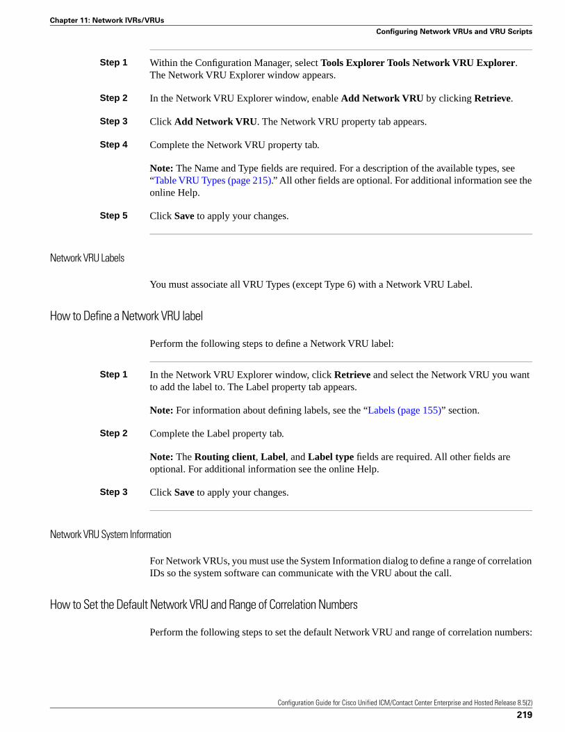
Step 1 Within the Configuration Manager, select Tools Explorer Tools Network VRU Explorer.The Network VRU Explorer window appears.
Step 2 In the Network VRU Explorer window, enable Add Network VRU by clicking Retrieve.
Step 3 Click Add Network VRU. The Network VRU property tab appears.
Step 4 Complete the Network VRU property tab.
Note: The Name and Type fields are required. For a description of the available types, see“Table VRU Types (page 215).” All other fields are optional. For additional information see theonline Help.
Step 5 Click Save to apply your changes.
Network VRU Labels
You must associate all VRU Types (except Type 6) with a Network VRU Label.
How to Define a Network VRU label
Perform the following steps to define a Network VRU label:
Step 1 In the Network VRU Explorer window, click Retrieve and select the Network VRU you wantto add the label to. The Label property tab appears.
Note: For information about defining labels, see the “Labels (page 155)” section.
Step 2 Complete the Label property tab.
Note: The Routing client, Label, and Label type fields are required. All other fields areoptional. For additional information see the online Help.
Step 3 Click Save to apply your changes.
Network VRU System Information
For Network VRUs, you must use the System Information dialog to define a range of correlationIDs so the system software can communicate with the VRU about the call.
How to Set the Default Network VRU and Range of Correlation Numbers
Perform the following steps to set the default Network VRU and range of correlation numbers:
Configuration Guide for Cisco Unified ICM/Contact Center Enterprise and Hosted Release 8.5(2)
219
Chapter 11: Network IVRs/VRUs
Configuring Network VRUs and VRU Scripts
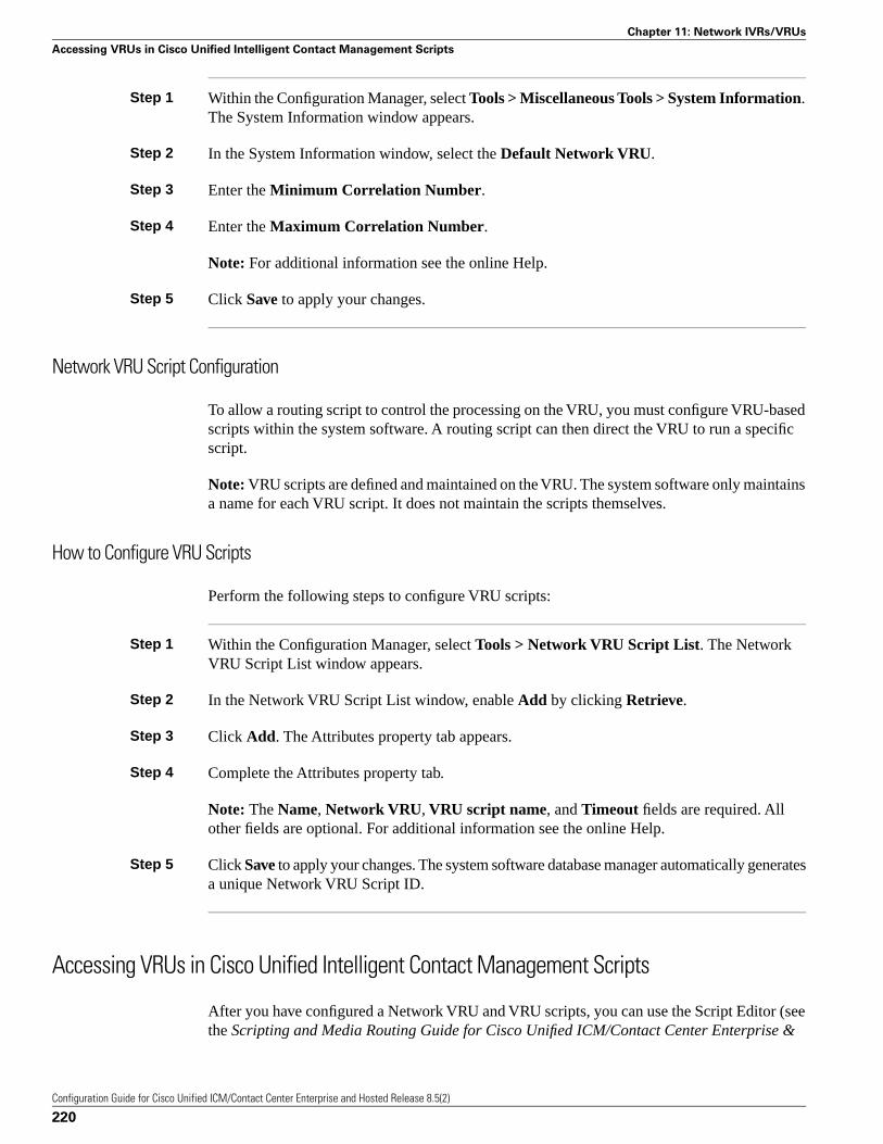
Step 1 Within the Configuration Manager, select Tools > Miscellaneous Tools > System Information.The System Information window appears.
Step 2 In the System Information window, select the Default Network VRU.
Step 3 Enter the Minimum Correlation Number.
Step 4 Enter the Maximum Correlation Number.
Note: For additional information see the online Help.
Step 5 Click Save to apply your changes.
Network VRU Script Configuration
To allow a routing script to control the processing on the VRU, you must configure VRU-basedscripts within the system software. A routing script can then direct the VRU to run a specificscript.
Note: VRU scripts are defined and maintained on the VRU. The system software only maintainsa name for each VRU script. It does not maintain the scripts themselves.
How to Configure VRU Scripts
Perform the following steps to configure VRU scripts:
Step 1 Within the Configuration Manager, select Tools > Network VRU Script List. The NetworkVRU Script List window appears.
Step 2 In the Network VRU Script List window, enable Add by clicking Retrieve.
Step 3 Click Add. The Attributes property tab appears.
Step 4 Complete the Attributes property tab.
Note: The Name, Network VRU, VRU script name, and Timeout fields are required. Allother fields are optional. For additional information see the online Help.
Step 5 Click Save to apply your changes. The system software database manager automatically generatesa unique Network VRU Script ID.
Accessing VRUs in Cisco Unified Intelligent Contact Management Scripts
After you have configured a Network VRU and VRU scripts, you can use the Script Editor (seethe Scripting and Media Routing Guide for Cisco Unified ICM/Contact Center Enterprise &
Configuration Guide for Cisco Unified ICM/Contact Center Enterprise and Hosted Release 8.5(2)
220
Chapter 11: Network IVRs/VRUs
Accessing VRUs in Cisco Unified Intelligent Contact Management Scripts

Hosted for additional information) to write a routing script to send a call to the VRU and invokea specific VRU script.
Queuing Calls at VRUs
You can queue a call at a Network VRU until a specific resource becomes available. A call canbe queued for one or more skill groups, an enterprise skill group, or one or more scheduledtargets. As soon as an agent becomes available at one of the specified targets, the call is removedfrom queue and sent to the target.
Configuration Guide for Cisco Unified ICM/Contact Center Enterprise and Hosted Release 8.5(2)
221
Chapter 11: Network IVRs/VRUs
Queuing Calls at VRUs

Configuration Guide for Cisco Unified ICM/Contact Center Enterprise and Hosted Release 8.5(2)
222
Chapter 11: Network IVRs/VRUs
Queuing Calls at VRUs

Peripheral Terminology
Overview
Different peripheral manufacturers use different terminology for agents, skill groups, andservices. For example, a service might be called an application, split, or gate. A skill groupmight be called an agent group or hunt group.
For example, note the following about using peripherals with Unified ICM:
1. The Aspect contact center maps a trunk group and DNIS to a Call Control Table (CCT).The DEFINITY ECS uses the trunk group and DNIS for incoming calls.
2. Without Customer Controlled Routing (CCR), one or more services map to an ACD DN.With CCR, one or more services map to an ACD CDN.
3. If an ECS is running in Expert Agent Selection (EAS) mode, a skill group maps to an ECSskill group; otherwise, it maps to a hunt group.
4. A contact center instrument can be a trunk, a teleset, or a workstation.
5. Define one network trunk group and one associated trunk group for each DMS-100,DMS-500, and SL-100.
Mapping Cisco Unified Intelligent Contact Management Terminology to ACD-specificTerminology
The following table summarizes the mapping of Unified ICM terminology to ACD-specificterminology.
Configuration Guide for Cisco Unified ICM/Contact Center Enterprise and Hosted Release 8.5(2)
223
Appendix A
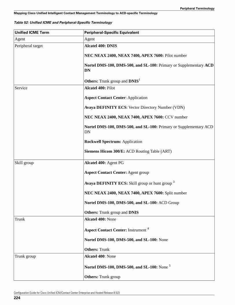
Table 52: Unified ICME and Peripheral-Specific Terminology
Peripheral-Specific EquivalentUnified ICME Term
AgentAgent
Alcatel 400: DNISPeripheral target
NEC NEAX 2400, NEAX 7400, APEX 7600: Pilot number
Nortel DMS-100, DMS-500, and SL-100: Primary or Supplementary ACDDN
Others: Trunk group and DNIS1
Alcatel 400: PilotService
Aspect Contact Center: Application
Avaya DEFINITY ECS: Vector Directory Number (VDN)
NEC NEAX 2400, NEAX 7400, APEX 7600: CCV number
Nortel DMS-100, DMS-500, and SL-100: Primary or Supplementary ACDDN
Rockwell Spectrum: Application
Siemens Hicom 300/E: ACD Routing Table (ART)
Alcatel 400: Agent PGSkill group
Aspect Contact Center: Agent group
Avaya DEFINITY ECS: Skill group or hunt group 3
NEC NEAX 2400, NEAX 7400, APEX 7600: Split number
Nortel DMS-100, DMS-500, and SL-100: ACD Group
Others: Trunk group and DNIS
Alcatel 400: NoneTrunk
Aspect Contact Center: Instrument 4
Nortel DMS-100, DMS-500, and SL-100: None
Others: Trunk
Alcatel 400: NoneTrunk group
Nortel DMS-100, DMS-500, and SL-100: None 5
Others: Trunk group
Configuration Guide for Cisco Unified ICM/Contact Center Enterprise and Hosted Release 8.5(2)
224
Peripheral Terminology
Mapping Cisco Unified Intelligent Contact Management Terminology to ACD-specific Terminology

Note: Multi-channel applications function as application instances. See Chapter 9, “ConfiguringCisco Unified Intelligent Contact Management Software for Integrated Applications (page 177),”for more information about these applications.
In some cases the Unified ICM concept is very close to the corresponding ACD feature. Forexample, the Unified ICM concept of a service is very similar to the Aspect concept of anapplication. In other cases, the ACD does not have a feature that maps exactly to the UnifiedICM feature. In these cases, you might choose a different mapping than shown in the “CiscoUnified Intelligent Contact Management Software and Peripheral-Specific Terminology (page223)” table. For example, although it might make sense to associate each VDN on a DEFINITYECS with a Unified ICM service, you could also map each hunt group to a service.
On an Avaya DEFINITY ECS running in EAS mode, each skill group has primary and secondarysubgroups. The system software emulates this by automatically creating additional skill groupsfor these peripheral types. For example, when you configure the Sales skill group for an AvayaDEFINITY ECS ACD, the system software automatically creates the Sales.pri and Sales.secskill groups in addition to the base Sales group. In monitoring and scripts, you can referencethe .pri and .sec skill groups directly or you can refer to the base skill group.
Some ACDs have limitations that prevent them from making full use of specific features of thesystem software.
See Also
See the Pre-installation Planning Guide for Cisco Unified ICM Enterprise and Hosted for thecurrent list of supported peripherals with peripheral-specific limitations.
Configuration Guide for Cisco Unified ICM/Contact Center Enterprise and Hosted Release 8.5(2)
225
Peripheral Terminology
Mapping Cisco Unified Intelligent Contact Management Terminology to ACD-specific Terminology

Configuration Guide for Cisco Unified ICM/Contact Center Enterprise and Hosted Release 8.5(2)
226
Peripheral Terminology
Mapping Cisco Unified Intelligent Contact Management Terminology to ACD-specific Terminology
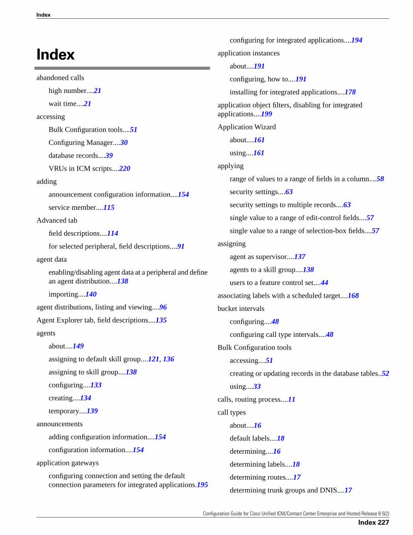
Index
abandoned calls
high number....21
wait time....21
accessing
Bulk Configuration tools....51
Configuring Manager....30
database records....39
VRUs in ICM scripts....220
adding
announcement configuration information....154
service member....115
Advanced tab
field descriptions....114
for selected peripheral, field descriptions....91
agent data
enabling/disabling agent data at a peripheral and definean agent distribution....138
importing....140
agent distributions, listing and viewing....96
Agent Explorer tab, field descriptions....135
agents
about....149
assigning to default skill group....121, 136
assigning to skill group....138
configuring....133
creating....134
temporary....139
announcements
adding configuration information....154
configuration information....154
application gateways
configuring connection and setting the defaultconnection parameters for integrated applications.195
configuring for integrated applications....194
application instances
about....191
configuring, how to....191
installing for integrated applications....178
application object filters, disabling for integratedapplications....199
Application Wizard
about....161
using....161
applying
range of values to a range of fields in a column....58
security settings....63
security settings to multiple records....63
single value to a range of edit-control fields....57
single value to a range of selection-box fields....57
assigning
agent as supervisor....137
agents to a skill group....138
users to a feature control set....44
associating labels with a scheduled target....168
bucket intervals
configuring....48
configuring call type intervals....48
Bulk Configuration tools
accessing....51
creating or updating records in the database tables..52
using....33
calls, routing process....11
call types
about....16
default labels....18
determining....16
determining labels....18
determining routes....17
determining trunk groups and DNIS....17
Configuration Guide for Cisco Unified ICM/Contact Center Enterprise and Hosted Release 8.5(2)
Index 227
Index
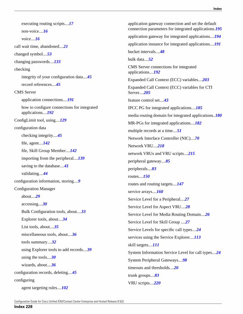
executing routing scripts....17
non-voice....16
voice....16
call wait time, abandoned....21
changed symbol....53
changing passwords....133
checking
integrity of your configuration data....45
record references....45
CMS Server
application connections....191
how to configure connections for integratedapplications....192
ConfigLimit tool, using....129
configuration data
checking integrity....45
file, agent....142
file, Skill Group Member....142
importing from the peripheral....139
saving to the database....41
validating....44
configuration information, storing....9
Configuration Manager
about....29
accessing....30
Bulk Configuration tools, about....33
Explorer tools, about....34
List tools, about....35
miscellaneous tools, about....36
tools summary....32
using Explorer tools to add records....39
using the tools....30
wizards, about....36
configuration records, deleting....45
configuring
agent targeting rules....102
application gateway connection and set the defaultconnection parameters for integrated applications.195
application gateway for integrated applications....194
application instance for integrated applications....191
bucket intervals....48
bulk data....52
CMS Server connections for integratedapplications....192
Expanded Call Context (ECC) variables....203
Expanded Call Context (ECC) variables for CTIServer....205
feature control set....43
IPCC PG for integrated applications....185
media routing domain for integrated applications..180
MR-PGs for integrated applications....182
multiple records at a time....51
Network Interface Controller (NIC)....70
Network VRU....218
network VRUs and VRU scripts....215
peripheral gateway....85
peripherals....83
routes....150
routes and routing targets....147
service arrays....160
Service Level for a Peripheral....27
Service Level for Aspect VRU....28
Service Level for Media Routing Domain....26
Service Level for Skill Group ....27
Service Levels for specific call types....24
services using the Service Explorer....113
skill targets....111
System Information Service Level for call types....24
System Peripheral Gateways....98
timeouts and thresholds....20
trunk groups....83
VRU scripts....220
Configuration Guide for Cisco Unified ICM/Contact Center Enterprise and Hosted Release 8.5(2)
Index 228
Index
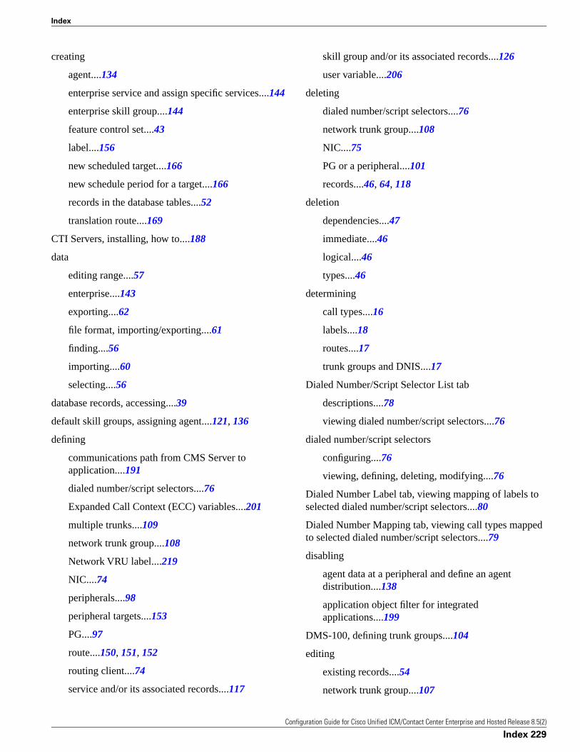
creating
agent....134
enterprise service and assign specific services....144
enterprise skill group....144
feature control set....43
label....156
new scheduled target....166
new schedule period for a target....166
records in the database tables....52
translation route....169
CTI Servers, installing, how to....188
data
editing range....57
enterprise....143
exporting....62
file format, importing/exporting....61
finding....56
importing....60
selecting....56
database records, accessing....39
default skill groups, assigning agent....121, 136
defining
communications path from CMS Server toapplication....191
dialed number/script selectors....76
Expanded Call Context (ECC) variables....201
multiple trunks....109
network trunk group....108
Network VRU label....219
NIC....74
peripherals....98
peripheral targets....153
PG....97
route....150, 151, 152
routing client....74
service and/or its associated records....117
skill group and/or its associated records....126
user variable....206
deleting
dialed number/script selectors....76
network trunk group....108
NIC....75
PG or a peripheral....101
records....46, 64, 118
deletion
dependencies....47
immediate....46
logical....46
types....46
determining
call types....16
labels....18
routes....17
trunk groups and DNIS....17
Dialed Number/Script Selector List tab
descriptions....78
viewing dialed number/script selectors....76
dialed number/script selectors
configuring....76
viewing, defining, deleting, modifying....76
Dialed Number Label tab, viewing mapping of labels toselected dialed number/script selectors....80
Dialed Number Mapping tab, viewing call types mappedto selected dialed number/script selectors....79
disabling
agent data at a peripheral and define an agentdistribution....138
application object filter for integratedapplications....199
DMS-100, defining trunk groups....104
editing
existing records....54
network trunk group....107
Configuration Guide for Cisco Unified ICM/Contact Center Enterprise and Hosted Release 8.5(2)
Index 229
Index
records....54
enabling agent data at a peripheral and defining an agentdistribution....138
enterprise services, creating and assigning specificservices....144
enterprise skill groups, creating....144
executing scripts....17
expanded call context
defining variable....203
setting Enabled option....203
Expanded Call Context (ECC) variables
configuring....203
configuring for CTI Server....205
with Collaboration....202
Explorer tools, using....34
exporting data....62
feature control
node control table....42
restricting users or classes of users....41
script node control....42
feature control set
assigning users....44
configuring....43
creating....43
selecting script nodes....44
features
bulk configuration....53
common bulk, list, and explorer tool....37
network IVRs/VRUs....207
finding data....56
importing
agent data....140
data....60
inserting new records....59
installing
application instances for integrated applications....178
CTI Server for integrated applications....188
IPCC PGs for integrated applications....186
Intelligent Call Processing subsystems....69
IPCC PGs
configuring for integrated applications....185
installing for integrated applications....186
labels
associating with a scheduled target....168
creating....156
default....18
defining....155
internal mappings....18
mapping....158
mapping specific labels to a dialed number/scriptselector....158
setting default label for a dialed number/scriptselector....159
special Sprint....156
types....155
Label tab
field descriptions....116, 125
late thresholds....21
limit, skill groups....128
List tools, using....34
Logical Controller tab field descriptions....86
logical interface controller....69
Logical Interface Controller tab, configuring NIC androuting client(s), field descriptions....70
mapping
skill groups to services....128
specific labels to a dialed number/script selector...158
media routing domains
configuring for integrated applications....180
creating a default route....95
miscellaneous tools, using....36
modifying
Configuration Guide for Cisco Unified ICM/Contact Center Enterprise and Hosted Release 8.5(2)
Index 230
Index
agent record....133
dialed number/script selectors....76
NIC or its routing client(s)....73
PG or peripheral....100
route....151, 152
service....117
skill group....125
MR-PGs
configuring for integrated applications....182
setting up for integrated applications....183
network interface controllers, about....68
network trunk groups
defining....108
deleting....108
editing....107
viewing....104
Network Trunk Group tab descriptions....105
Network VRU Banks tab....210
Network VRU Explorer
Network Applications Manager....208
Network VRU Label Tree....208
Network VRU Explorer tool....208
Network VRU Label Tree
Add....209
Add Label....210
Add Network VRU ....209
Delete....210
Hide/Show legend....208
ID status box....210
Security....210
Tree list box....209
Undelete....210
Network VRUs
configuring....218
defining a label....219
labels....219
script configuration....220
script data descriptions....218
setting default Network VRU and range of correlationnumbers....219
Network VRU Script List tool
about....211
Attributes tab....212
Network VRU Script List box....211
Security tab....212
Network VRU tab....210
NICs
defining....74
deleting....75
modifying....73
viewing....70
not changed symbol....53
object control, prohibiting access to configuration data.41
online help, Configuration Manager....31
passwords, changing....133
peripheral gateways
about....68
configuring....85
configuring agent targeting rules....102
deleting a PG....101
viewing records....85
peripherals
Advanced tab field descriptions....91
calls to skill targets....103
configuring agent targeting rules....102
Default Route tab field descriptions....95
defining....98
defining PGs....97
deleting....101
gateways, about....84
modifying records....100
Configuration Guide for Cisco Unified ICM/Contact Center Enterprise and Hosted Release 8.5(2)
Index 231
Index
overview....84
Peripheral Monitor tab field descriptions....93
Peripheral tab field descriptions....89
processing....19
subsystem....84
Peripheral tab, field descriptions....89
peripheral targets, defining....153
Peripheral Target tab, field descriptions....115, 124
peripheral terminology
ACD routing table....224
agent....224
application....224
peripheral targets....224
service....224
skill group....224
terminology overview....223
trunk....224
trunk group....224
vector directory number....224
Person List tool, storing person records....130
Person List tool tab, field descriptions....132
PG Explorer tool, tab descriptions....86
PGs
configuring agent targeting rules....102
defining....97
deleting....101
Physical Interface Controller tab, viewing selected NIC'sphysical interface controller properties, fielddescriptions....71
private network peripherals, routing clients....67
public network interexchange carriers, routing clients...67
queuing calls at VRUs....221
receiving routing responses....20
record references, checking....45
records
administering deleted....47
applying security settings to multiple....63
configuring multiple....51
deleting....46, 118
deleting and undeleting....64
finding data....56
inserting new....59
modifying a PG and peripheral....100
Peripheral Monitor....93
retrieving and editing existing....54
selecting....56
selecting one field in multiple....56
sorting....55
sorting by multiple columns....55
viewing deleted....47
viewing or modifying agent....133
viewing PG....85
Record State....53
removing service member....115
reporting
call type configuration....24
retrieving
data from the database....131
existing records....54
records....54
route requests, how system software processes....15
routes
configuration overview....150
defining and updating....150
defining or modifying....151, 152
determining....17
how to select multiple skill groups and routes fordifferent media by agent expression for integratedapplications....197
how to select multiple skill groups and routes fordifferent media by agent for integratedapplications....196
translation....168
Configuration Guide for Cisco Unified ICM/Contact Center Enterprise and Hosted Release 8.5(2)
Index 232
Index
Route tab
field descriptions....115, 123
routing
creating a default route for each Media RoutingDomain....95
how it works....11
process....11
process steps....12
requests, about....13
targets, Unified ICM....149
routing clients
CRSP....75
defining....74
examples....68
processing....18
receiving routing responses....20
Routing Client tab field descriptions....92
Sprint....75
subsystem....67
viewing a NIC....70
working with trunk groups....104
Routing Client tab, viewing selected routing clientproperties....72
routing requests
about....13
Caller-Entered Digits (CED)....13
Calling Line ID (CLID)....13
Dialed Number (DN)....13
Post-Routing....13
Pre-Routing....13
route and target subsystem....148
saving configuration data to the database....41
scheduled targets
about....165
associating labels....168
creating a new....166
creating a new schedule period....166
scripts
administrative....9
executing....17
managing....9
routing....9
security settings, applying to multiple records....63
selecting
data from the database....131
multiple skill groups and routes for different media byagent expression for integrated applications....197
multiple skill groups and routes for different media byagent for integrated applications....196
one field in multiple records....56
records....56
script nodes for a feature control set....44
service arrays
about....159
configuring....160
Service Explorer tool, viewing and configuring aservice....113
service levels
about....22
configuring....23
threshold....22
types....22
Service Members tab, field descriptions....115
services
about....112, 149
defining....117
enterprise....143
modifying....117
viewing....113
Service tab, field descriptions....113
setting
default label for a dialed number/script selector....159
Configuration Guide for Cisco Unified ICM/Contact Center Enterprise and Hosted Release 8.5(2)
Index 233
Index
default Network VRU and range of correlationnumbers....219
expanded call context Enabled option....203
expanded call context variable....203
setting up MR-PGs for integrated applications....183
Skill Group Explorer tool, viewing and configuring skillgroups....119
Skill Group Mask tab
field descriptions....122
viewing default number of subskill groups....91
Skill Group Membership tab
assigning agent to default skill group....136
field descriptions....136
Skill Group Members tab
assigning agent to default skill group....121
field descriptions....121
skill groups
about....149
assigning agent to default....121, 136
defining....126
enterprise....144
how to select multiple skill groups and routes fordifferent media by agent expression for integratedapplications....197
how to select multiple skill groups and routes fordifferent media by agent for integratedapplications....196
mapping to services....128
modifying....125
viewing....119
skill groups, limit....128
Skill Group tab, field descriptions....119
Skill Group table....46
skill targets
configuring....111
subsystem....112
sorting records by multiple columns....55
Sub Skill Groups tab, field descriptions....123
Supervisor tab, field descriptions....137
symbols
changed....53
not changed....53
record status....37
to be deleted....53
to be inserted....53
System Peripheral Gateways, configuring....98
system software overview....7
tabs
Advanced tab field descriptions....91
Agent Distribution tab field descriptions....96
Default Route tab field descriptions....95
Label tab field descriptions....211
Logical Controller tab field descriptions....86
Logical Interface Controller field descriptions....70
Network Trunk Group tab descriptions....105
Network VRU Banks tab field descriptions....210
Network VRU Script List tool Attributes tab fielddescriptions....212
Network VRU Script List tool Security tab....212
Network VRU tab field descriptions....210
Peripheral Monitor tab field descriptions....93
Peripheral tab field descriptions....89
Physical Interface Controller field descriptions....71
Routing Client field descriptions....72
Routing Client tab field descriptions....92
Service Explorer tab field descriptions....113
Skill Group Explorer tab field descriptions....119
Skill Group Mask....91
Trunk Group tab descriptions....106
Trunk tab descriptions....107
targets
about....13
network....152
Configuration Guide for Cisco Unified ICM/Contact Center Enterprise and Hosted Release 8.5(2)
Index 234
Index
peripheral target....14
skill target....13
tasks
how to access the Bulk Configuration tools....51
how to add announcement configurationinformation....154
how to apply a range of values to a range of fields ina column....58
how to apply a single value to a range of edit-controlfields....57
how to apply a single value to a range of selection-boxfields....57
how to assign agents to a skill group....138
how to assign users to a feature control set....44
how to associate labels with a scheduled target....168
how to change your password....133
how to check record references....45
how to check the integrity of your configurationdata....45
how to configure agent targeting rules....102
how to configure an application gateway....194
how to configure an application gateway connectionand set the default connection parameters....195
how to configure a Network VRU....218
how to configure bucket intervals....48
how to configure CMS Server connections....192
how to configure service arrays....160
how to configure the application instance for integratedapplications....191
how to configure the IPCC PG....185
how to configure the media routing domain....180
how to configure the MR-PG....182
how to configure VRU scripts....220
how to create a feature control set....43
how to create a label....156
how to create an agent....134
how to create a new scheduled target....166
how to create a new schedule period for a target....166
how to create a translation route....169
how to create enterprise service and assign specificservices....144
how to create enterprise skill group....144
how to define and update a route....150
how to define a network trunk group....108
how to define a Network VRU label....219
how to define a NIC....74
how to define a peripheral....98
how to define a PG....97
how to define a routing client....74
how to define a service and/or its associatedrecords....117
how to define a skill group and/or its associatedrecordds....126
how to define a user variable....206
how to define multiple trunks....109
how to define or modify a route....151, 152
how to define peripheral targets....153
how to define the expanded call context variable...203
how to delete a network trunk group....108
how to delete a NIC....75
how to delete a PG or a peripheral....101
how to delete a record....46, 118
how to delete records....64
how to disable an application object filter....199
how to edit a network trunk group....107
how to enable/disable agent data at a peripheral anddefine an agent distribution....138
how to export data....62
how to find data....56
how to import agent data....140
how to import data....60
how to insert new records....59
how to install CTI Server for integratedapplications....188
Configuration Guide for Cisco Unified ICM/Contact Center Enterprise and Hosted Release 8.5(2)
Index 235
Index
how to install the application instance....178
how to install the IPCC PG....186
how to map skill groups to services....128
how to map specific labels to a dialed number/scriptselector....158
how to modify a NIC or its routing client(s)....73
how to modify a PG and peripheral records....100
how to modify a service....117
how to modify a skill group....125
how to retrieve and edit existing records....54
how to select multiple skill groups and routes fordifferent media by agent....196
how to select multiple skill groups and routes fordifferent media by agent expression....197
how to select one field in multiple records....56
how to select records....56
how to select script nodes for a feature control set...44
how to set a default label for a dialed number/scriptselector....159
how to set the default Network VRU and range ofcorrelation numbers....219
how to set the expanded call context Enabledoption....203
how to set up the MR-PG....183
how to sort records by multiple columns....55
how to undelete records....65
how to use the Application Wizard....161
how to view, define, delete, or modify dialednumber/script selectors....76
how to view a network trunk group....104
how to view a NIC and its routing client(s)....70
how to view a service....113
how to view a skill group....119
how to view deleted records....47
how to view or apply security settings....63
how to view or modify agent record....133
thresholds
about....20
late....21
timeout....20
Timeout limit....72
timeouts
about....20
limit....21
threshold....20
Timeout threshold....72
to be deleted symbol....53
to be inserted symbol....53
tools
Bulk Configuration....33
ConfigLimit....129
Explorer....34
List....34
miscellaneous....36
wizards....36
tracking agent states....139
translation routes
about....19
creating....169
Translation Route Wizard, about....169
Trunk Group tab, descriptions....106
trunks, defining multiple....109
Trunk tab
descriptions....107
trunk types....107
types of deletions
immediate deletion....46
logical deletion....46
undeleting records....65
Unified CCE, overview....8
Unified ICM
overview....7
Configuration Guide for Cisco Unified ICM/Contact Center Enterprise and Hosted Release 8.5(2)
Index 236
Index
routing targets....149
updating
records in the database tables....52
route....150
user variables
about....205
defining....206
using
Application Wizard....161
Bulk Configuration tools....33
Configuration Manager....29, 30
Explorer tools....34
List tools....34
miscellaneous tools....36
wizards....36
variables
Expanded Call Context (ECC)....201
user....205
viewing
agent distributions....96
agent record....133
deleted records....47
dialed number/script selectors....76
network trunk group....104
NIC and its routing client(s)....70
PG records....85
security settings....63
selected NIC's physical interface controllerproperties....71
selected routing client properties....72
service....113
skill group....119
VRU configuration tools, about....208
VRU Currency List tool....212
Attributes tab....213
VRU Currency List box....212
VRU Defaults List tool
about....213
Attributes tab....213
VRU Currency List box....213
VRU Locale....215
VRU Locale List tool
about....215
Attributes tab....215
VRU Locales List box....215
VRU port maps, data description....217
VRU scripts, configuring....220
windows, Insert and Edit....52
wizards, using....36
Configuration Guide for Cisco Unified ICM/Contact Center Enterprise and Hosted Release 8.5(2)
Index 237
Index