Embed Size (px)
Citation preview
Configurable SDR Operation for Cognitive Radio
Applications using GNU Radio and the Universal Software Radio Peripheral
David A. Scaperoth
Thesis submitted to the faculty of the Virginia Polytechnic Institute and State University in partial fulfillment of the requirements for the degree of
Master of Science
In Electrical Engineering
Dr. Charles W. Bostian, Chair Dr. Allen B. MacKenzie
Dr. Scott F. Midkiff
May 4, 2007 Blacksburg, Virginia
Keywords: Wireless, Cognitive Radio, Software Radio, Software Defined Radio, GNU
Radio, USRP
Configurable SDR Operation for Cognitive Radio Applications using GNU Radio and the Universal Software
Radio Peripheral
David A. Scaperoth
Dr. Charles W. Bostian, Chairman
Electrical Engineering
(ABSTRACT)
With interoperability issues plaguing emergency responders throughout the country,
Cognitive Radio (CR) offers a unique solution to streamline communication between
police, Emergency Medical Technicians (EMT), and military officers. Using Software
Defined Radio (SDR) technology, a flexible radio platform can be potentially configured
using a Cognitive Engine (CE) to transmit and receive many different incompatible radio
standards. In this thesis, an interface between a Cognitive Engine and an SDR platform
is described which modifies (i.e., configures) the radio’s operation. The interface is
based upon communicating information via eXtensible Markup Language (XML) data
files that contain the radio’s Physical (PHY) parameters. The XML data files have been
designed such that more development can be made to its structure as this research
develops. The GNU Radio and the Universal Software Radio Peripheral (USRP) serve as
the SDR platform for an example implementation. The example implementation involves
importing XML data files into the SDR for quick configuration. Three configuration
examples are used to describe this process.

For Paige
You give meaning to it all.
David A. Scaperoth Acknowledgments iv
Acknowledgements
I would first like to thank my savior Jesus Christ. Whose presence in my life has lead me
here and now more than ever I realize how amazing His timing is.
I would like to thank my parents for their unceasing love for me and their faith that I
could accomplish anything that I put my mind to.
I would like to thank my loving wife Paige for not only her understanding, but for her
continuous love and encouragement. Because of her presence in the midst of this work,
this journey has been a pleasure and a time in my life I will never forget.
I would also like to thank my advisor, Dr. Bostian, who has done nothing but challenge
and encourage me from the day I have gotten here. From the beginning, he has made me
feel apart of the CWT family. I am grateful for the unity that he has fostered throughout
our group, and the wisdom he has shown as an advisor and a mentor will be something
that I will never forget.
I would like to thank my committee members, Dr. Allen MacKenzie and Dr. Scott
Midkiff for their contribution to this world-wind-tour of a Master’s Thesis.
To Tom Rondeau and Bin Le, YOU GUYS ROCK! Your patience, commitment, and
most importantly your passion for your work has truly been infectious. You always made
me feel like I made a difference while I was here.
Thank you to all those at the Wireless at VT team, especially: Judy Hood, David
Maldonado, Daniel Friend, Akilah Hugine, Scott Brock, Jacob DePriest, Chen Chen,
Jody Neal, Joeseph Gaeddert, Terry Brisebois, and Mark Silvius. You have all been great
to work with but also good friends in the midst of it all.
David A. Scaperoth Grant Information v
Grant Information
This project is supported by Award No. 2005-IJ-CX-K017 awarded by the
National Institute of Justice, Office of Justice Programs, US Department
of Justice. The opinions, findings, and conclusions or recommendations
expressed in this publication/program/exhibition are those of the
author(s) and do not necessarily reflect the views of the Department of
Justice.
This material is based upon work supported by the National Science
Foundation under Grants No. 9983463, DGE-9987586, and CNS-0519959. Any
opinions, findings and conclusions or recommendations expressed in this
material are those of the author(s) and do not necessarily reflect the
views of the National Science Foundation (NSF).
David A. Scaperoth Contents vi
Contents
1 Introduction...............................................................................................................1
1.1 Motivations: Cognitive Radio as an Interoperability Solution .............................1
1.2 Contributions......................................................................................................2
1.3 Thesis Organization............................................................................................2
2 Background ...............................................................................................................4
2.1 Introduction........................................................................................................4
2.2 Software Defined Radio (SDR)...........................................................................4
2.3 Cognitive Radio (CR) .........................................................................................4
2.4 Universal Software Radio Peripheral (USRP) .....................................................5
2.4.1 Introduction .................................................................................................5
2.4.2 Limitations of the USRP ..............................................................................7
2.5 GNU Radio.........................................................................................................8
2.5.1 Introduction .................................................................................................8
2.5.2 GNU Radio Flow Graphs.............................................................................9
2.5.3 GNU Radio Example Flow Graph: AM Transmitter................................... 10
2.5.4 Limitations of GNU Radio......................................................................... 13
2.6 Related Work for GNU Radio and the USRP.................................................... 13
2.7 Related Work in Cognitive Radio ..................................................................... 14
3 The Configuration Interface of a Software Defined Radio (SDR) and a Cognitive
Engine (CE) .................................................................................................................. 15
David A. Scaperoth Contents vii
3.1 Software Defined Radio (SDR) XML files........................................................ 17
3.1.1 SDR XML Framework............................................................................... 18
3.1.2 Additional Features of the SDR XML Structure ......................................... 21
3.2 The SDR Definition XML File ......................................................................... 23
3.3 The SDR Behavior XML File ........................................................................... 27
3.4 Passing the Behavior Data to the SDR .............................................................. 28
4 Implementing the SDR XML using GNU Radio and the USRP............................... 29
4.1 The Python XML Parser ................................................................................... 30
4.2 The GNU Radio Translator............................................................................... 34
4.3 Example Implementation.................................................................................. 36
4.3.1 Wideband FM VHF Rx / Narrowband FM VHF Tx ................................... 37
4.3.2 Narrowband FM UHF Rx / Wideband FM VHF Tx ................................... 37
4.3.3 Narrowband FM UHF Rx / Narrowband FM VHF Tx................................ 38
5 Conclusions and Future Work.................................................................................. 40
Appendix A: SDR Behavior XML Demo Files.............................................................. 42
A.1 Wideband FM VHF Signal Reception.............................................................. 42
A.2 Narrowband FM UHF Signal Reception .......................................................... 43
A.3 Wideband FM VHF Transmission ................................................................... 43
A.4 Narrowband VHF FM Transmission ................................................................ 44
Bibliography ................................................................................................................. 45
Vita............................................................................................................................... 48
David A. Scaperoth List of Figures viii
List of Figures
Figure 2-1: USRP and a Host Device...............................................................................6
Figure 2-2: USRP Motherboard Block Diagram [6].........................................................7
Figure 2-3: Software Organization of Flow Graphs in GNU Radio................................ 10
Figure 2-4: GNU Radio flow graph blocks for an AM Transmitter ................................ 11
Figure 2-5: Example Flow Graph for an AM DSB Transmitter...................................... 11
Figure 3-1: Simple Diagram of a Cognitive Engine Configuring a Software Defined
Radio (emphasizing the interface components in grey) ......................................... 16
Figure 3-2: Simple Diagram of the Flow of XML Data to Configure an SDR................ 18
Figure 4-1: Modulation Order from an SDR Behavior File ............................................ 32
Figure 4-2: Path Describing DAC Rate Unites from an SDR Behavior XML File.......... 33
Figure 4-3: Relationship Between SDR XML and GNU Radio Template Flow Graphs . 34
Figure 4-4: Demonstration Configuration VHF Wideband Rx / VHF Narrowband Tx with
the USRP............................................................................................................... 37
Figure 4-5: Demonstation Configuration UHF Narrowband Rx / VHF Wideband Tx with
the USRP............................................................................................................... 38
Figure 4-6: Demonstation Configuration UHF Narrowband Rx / VHF Narrowband Tx
with the USRP....................................................................................................... 39
David A. Scaperoth List of Tables ix
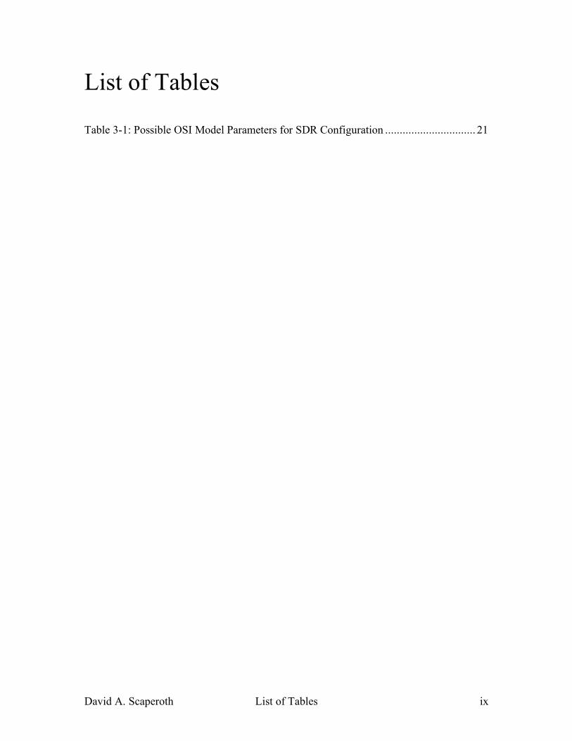
List of Tables
Table 3-1: Possible OSI Model Parameters for SDR Configuration ............................... 21
David A. Scaperoth List of Abbreviations x
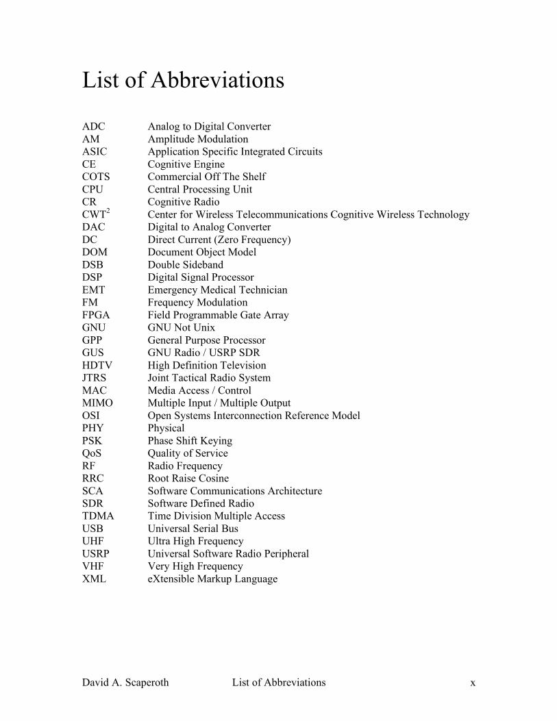
List of Abbreviations
ADC Analog to Digital Converter AM Amplitude Modulation ASIC Application Specific Integrated Circuits CE Cognitive Engine COTS Commercial Off The Shelf CPU Central Processing Unit CR Cognitive Radio CWT2 Center for Wireless Telecommunications Cognitive Wireless Technology DAC Digital to Analog Converter DC Direct Current (Zero Frequency) DOM Document Object Model DSB Double Sideband DSP Digital Signal Processor EMT Emergency Medical Technician FM Frequency Modulation FPGA Field Programmable Gate Array GNU GNU Not Unix GPP General Purpose Processor GUS GNU Radio / USRP SDR HDTV High Definition Television JTRS Joint Tactical Radio System MAC Media Access / Control MIMO Multiple Input / Multiple Output OSI Open Systems Interconnection Reference Model PHY Physical PSK Phase Shift Keying QoS Quality of Service RF Radio Frequency RRC Root Raise Cosine SCA Software Communications Architecture SDR Software Defined Radio TDMA Time Division Multiple Access USB Universal Serial Bus UHF Ultra High Frequency USRP Universal Software Radio Peripheral VHF Very High Frequency XML eXtensible Markup Language
David A. Scaperoth Chapter 1: Introduction 1
1 Introduction
1.1 Motivations: Cognitive Radio as an Interoperability Solution
For years, emergency responders (fire, police, EMT, etc.) and the armed forces
have battled with the problem of using wireless communication to interoperate between
each group. Software defined radios (SDRs) are the next technology to allow new levels
of flexibility within a single radio. One software defined radio could potentially support
the capabilities of many (if not all of) the radio’s in use by emergency responders. Even
with a flexible SDR, the ability to communicate with many different emergency
responders still becomes a difficult task. It is not uncommon for emergency responders to
encounter many problematic scenarios that are a fixture in the world of disaster relief: “If
I am in trouble, how do I know who is out there (e.g., what channel are the police on and
are they using P25 [26] or another type of radio)?” These kinds of problems have spurred
a variety of research topics including intelligent radio design, which allows not only for
signal detection capabilities, but also optimization of radio parameters (e.g., bandwidth,
bit error rates, filtering, etc.). The optimization can be done by a Cognitive Engine (CE),
which uses sophisticated learning algorithms to improve the Quality of Service (QoS)
provided by the radio to the user. The SDR, together with a CE, creates a Cognitive
Radio (CR) that could allow emergency responders to connect to each other seamlessly,
instead of worrying about radio details such as channel selection and waveform protocol.
David A. Scaperoth Chapter 1: Introduction 2
1.2 Contributions
In this paper, a cognitive radio implementation is developed. The Cognitive
Engine referenced in this paper is the Center for Wireless Telecommunications Cognitive
Wireless Technology’s (CWT)2 Cognitive Engine, and the prototype SDR platform is a
combination of the GNU Radio software package and the Universal Software Radio
Peripheral (USRP). Using XML files generated by a CE, the GNU Radio and USRP
SDR (GUS) is quickly configured for different analog waveforms. In this paper, only a
limited set of Physical Layer (PHY) SDR parameters are configurable, however, the
XML format introduced here allows for additional SDR parameters to be added as
research and development of the CR progresses. The framework of this XML format is
intended to allow a CE to interface and configure any SDR platform at potentially all
levels of the OSI stack. Three example waveforms will be used with the GUS
(narrowband FM, wideband FM, and AM DSB) as a proof-of-concept example of how to
configure an SDR with information that could be provided by a CE.
1.3 Thesis Organization
First, the background of a configurable radio (i.e. an SDR), and how it relates to a
Cognitive Radio will be discussed. Background will also be given on the GNU Radio
Project and the USRP and their contributions to the SDR community. Also to be
reviewed is work related to developing a standard interface between the SDR and a
Cognitive Engine for the purposes of configuring the radio . Chapter 3 discusses the
structural format of the XML files developed for communicating between the CE and the
David A. Scaperoth Chapter 1: Introduction 3
SDR. Chapter 4 elaborates on configuring multiple waveforms in the GUS using the
XML mentioned in Chapter 3. This discussion includes a description of a limited set of
SDR parameters that are controlled by the CE. Chapter 5 contains concluding remarks
and the current and future work being done in relation to the progress of the XML format
described in this paper.
David A. Scaperoth Chapter 2: Background 4
2 Background
2.1 Introduction
In this chapter, the basic characteristics of an SDR and a Cognitive Radio are
reviewed. Also, background is given on the GNU Radio Project and the Universal
Software Radio Peripheral (USRP), and related work done using the GNU Radio and the
USRP in the SDR community. Finally, there will be a brief look at related work being
done to interface cognitive functions to an SDR.
2.2 Software Defined Radio (SDR)
This section is a short description of the important features of the SDR (the terms
software radio and software defined radio are used interchangeably in this section). The
term software radio was first coined by Joseph Mitola in 1991 as a “class of
reprogrammable or reconfigurable radios [1].” According to Dr. Jeffrey Reed, a
professor at Virginia Tech and author of “Software Radio: A Modern Approach to Radio
Engineering” (2002), a software radio is a flexible radio that can accommodate formats
and protocols yet to be determined [2].
2.3 Cognitive Radio (CR)
Cognitive Radio (CR) was formally introduced to the radio community in 1999 by
Joseph Mitola and Gerald Q. Maguire, Jr. in [3] as an extension of an SDR, which served
David A. Scaperoth Chapter 2: Background 5
to improve the overall performance of the radio in relation to its interaction with the
spectrum using a cognition cycle. In [4], Mitola describes that a CR “is a goal-driven
framework in which the radio autonomously observes the radio environment, infers
context, assesses alternatives, generates plans, supervises multimedia services, and learns
from its mistakes.” While other definitions have been developed from research groups
across the SDR community, the two components that are most often considered core
features of the CR involve awareness of the RF environment and adaptation and/or
learning algorithms to improve the performance of the radio.
2.4 Universal Software Radio Peripheral (USRP)
2.4.1 Introduction
The USRP1 is an RF device with a simple design that allows for a wide range of
SDR related uses [5]. Since the USRP is not a stand-alone SDR, the USRP’s architecture
requires signal processing functions to be done on another host device via USB2.0.
Figure 2-1 shows the general setup of the USRP interacting with a host device to make an
SDR. The host device is primarily intended to be a personal computer with at least one
USB 2.0 connection, but the host device can be any kind of signal processing device that
can be connected via USB 2.0 (e.g., any kind of signal processing system that includes
components like General Purpose Processors (GPP), Digital Signal Processors (DSP),
Field Programmable Gate Arrays (FPGA), or Application Specific Integrated Circuits
(ASIC), etc.). 1 Reference to the USRP in context refers specifically to the USRP version 4
David A. Scaperoth Chapter 2: Background 6
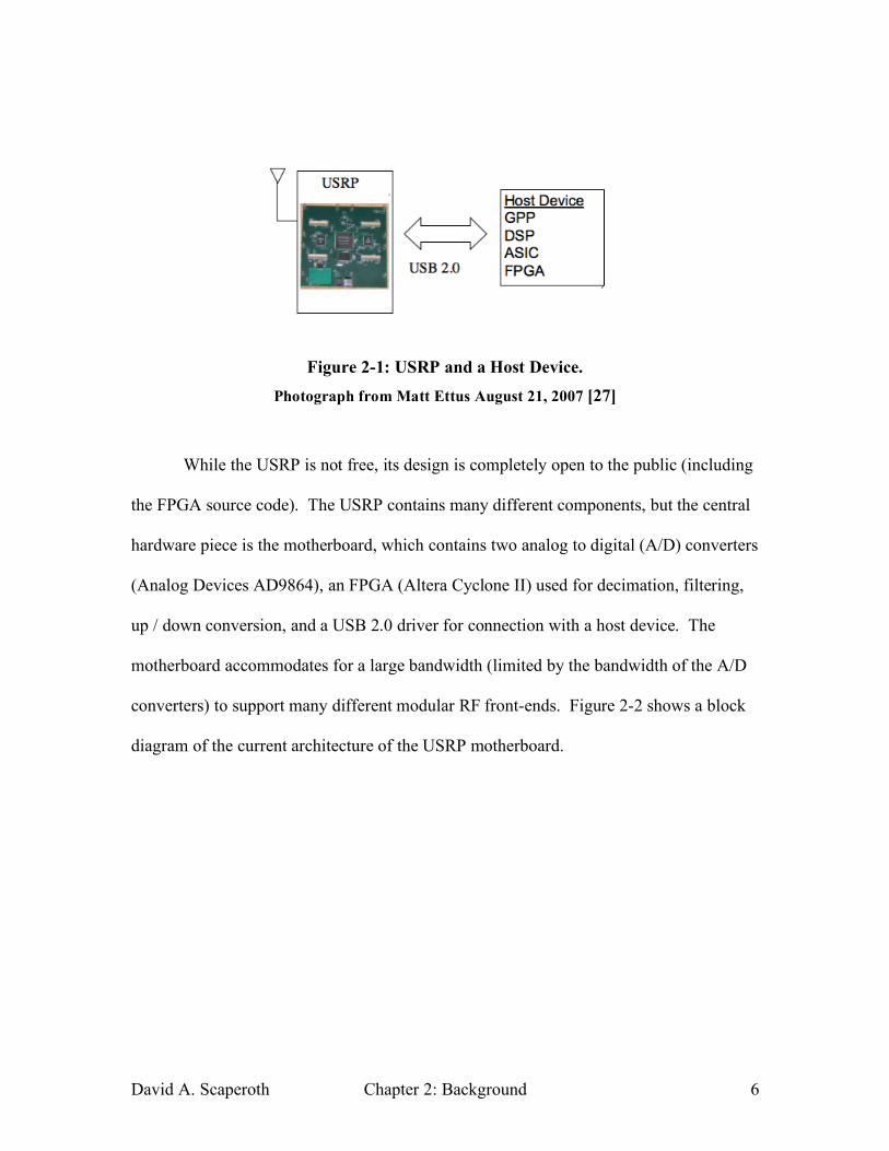
Figure 2-1: USRP and a Host Device. Photograph from Matt Ettus August 21, 2007 [27]
While the USRP is not free, its design is completely open to the public (including
the FPGA source code). The USRP contains many different components, but the central
hardware piece is the motherboard, which contains two analog to digital (A/D) converters
(Analog Devices AD9864), an FPGA (Altera Cyclone II) used for decimation, filtering,
up / down conversion, and a USB 2.0 driver for connection with a host device. The
motherboard accommodates for a large bandwidth (limited by the bandwidth of the A/D
converters) to support many different modular RF front-ends. Figure 2-2 shows a block
diagram of the current architecture of the USRP motherboard.

David A. Scaperoth Chapter 2: Background 7
Figure 2-2: USRP Motherboard Block Diagram Diagram from Lee Patton, August 18, 2007 [6]
Currently, 10 RF Front-ends (daughterboard’s) are available with frequency
ranges from DC to 2900MHz [7]. For each motherboard, multiple RF Front-ends can be
attached to the USRP (up to a maximum of four daughterboard’s – two transmit and two
receive). Because the USRP has a USB 2.0 interface, it is compatible with almost all
recently manufactured personal computers.
2.4.2 Limitations of the USRP
While the USRP is certainly a flexible SDR, limitations are inherent within any
radio design. The maximum throughput from the USRP to the host device is a well-
known limitation of the USRP. Some have reported the USB 2.0 interface can support
data rates around 32MS/s and an approximate bandwidth of about 6MHz of I/Q data and
12MHz of real data [8]. Because of this limitation, standards like the 802.11b/g (i.e.
David A. Scaperoth Chapter 2: Background 8
20MHz channels) are not feasible using the USRP. On the other hand, because most of
the signal processing is being done in the host device, the CPU’s processing power often
becomes an issue before the USB 2.0 device reaches its maximum throughput
boundaries. For example, HDTV reception is one of the early proof-of-concept
applications of the USRP. Because of HDTV’s 6MHz channel bandwidth, the
application was an ideal candidate to illustrate the USRP’s abilities. Although the USRP
can successfully down-convert HDTV frames, the time to process the frames is
significantly slower than real-time (40 seconds of processing for 1 second of data) using a
personal computer running Linux as the host device [9].
2.5 GNU Radio
2.5.1 Introduction
GNU Radio2 is a free collection of signal processing blocks that can be used for
RF real-time applications [10]. GNU Radio can act as a stand-alone software package or
as a backend to a hardware device. GNU Radio is written in both C++ and Python, and
programs are compiled and run on most general purpose processors (GPP’s) and
operating systems (e.g. Linux, Mac OSX, and Windows XP). Typically, the highest
level of programming done in GNU Radio is written in Python (i.e. initialization and
2 Because the GNU Radio architecture is often being improved to allow for a more robust
communications architecture, changes occur often that may deprecate the background material
done in this section. In order to clarify this work’s relation to GNU Radio, this thesis references
GNU Radio 3.0 when discussing GNU Radio in context.
David A. Scaperoth Chapter 2: Background 9
control for the signal processing components), and any time sensitive processing is done
in C++.
Currently, GNU Radio is the primary software platform supporting the drivers for
the USRP on a personal computer. The USRP’s software defined parameters (e.g. center
frequency, PGA gain, interpolation factor, decimation factor, and some transmit and
receive path multiplex options) can only be controlled using Python.
2.5.2 GNU Radio Flow Graphs
A GNU Radio flow graph is a group of signal processing blocks that are
connected together to make a communications system. When the flow graph blocks are
connected together, a GNU Radio flow graph, like an FFT plot of data from a file, an
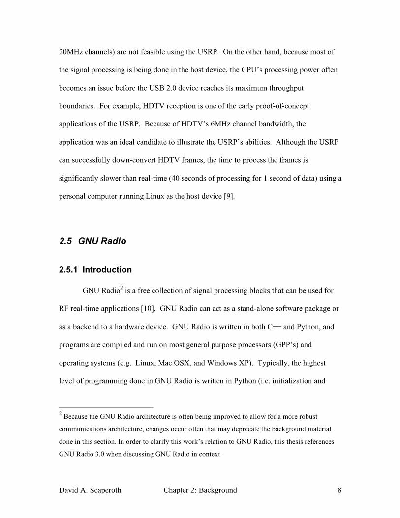
FM modulator, or a TDMA waveform, can be created. In Figure 2-3, the software
organization of the GNU Radio flow graphs is described (with emphasis on the
programming threads). The GNU Radio flow graphs are initialized within the primary
Python thread, and the control portion of the primary Python thread refers to any
modifications to the flow graph (e.g. multiplier, squelch level, etc.) while the program is
being executed. Any information (i.e. samples or bits) passed through a flow graph block
is done in the signal processing thread.
David A. Scaperoth Chapter 2: Background 10
Figure 2-3: Software Organization of Flow Graphs in GNU Radio
In order to start the flow graph, each of the blocks must be connected together using the
input and output ports of the flow graph block. The first block in the flow graph is called
a source block and only contains output connections. The source block can be a sine
wave, a set of samples stored in a file, a vector, or the USRP (for receiving), etc. The last
block in the flow graph is called the sink block and only contains input connections. The
sink block can be an output to a file, or a vector, or the USRP (for transmitting), etc. All
other blocks contain both input and output connections. In the following section, an
example using GNU Radio flow graphs and the flow graph blocks can be used to create a
simple AM transmitter will be presented.
2.5.3 GNU Radio Example Flow Graph: AM Transmitter
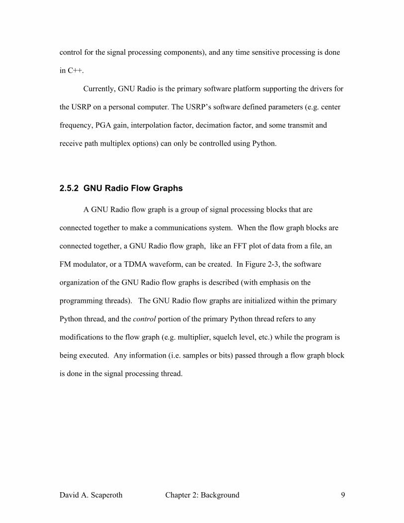
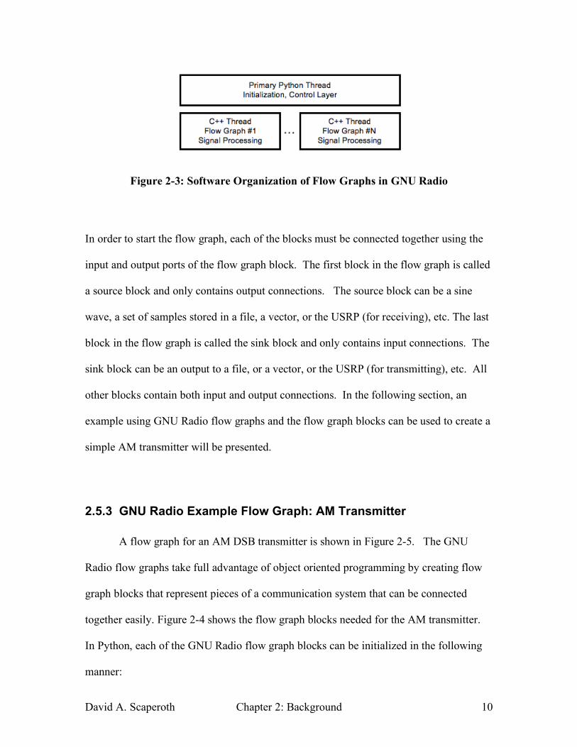
A flow graph for an AM DSB transmitter is shown in Figure 2-5. The GNU
Radio flow graphs take full advantage of object oriented programming by creating flow
graph blocks that represent pieces of a communication system that can be connected
together easily. Figure 2-4 shows the flow graph blocks needed for the AM transmitter.
In Python, each of the GNU Radio flow graph blocks can be initialized in the following
manner:
David A. Scaperoth Chapter 2: Background 11
audio_source = audio.source(complex_type, sampling_rate)
sum_by_one = gr.add_const_cc( 1 )
lowpass_filter = gr.interp_fir_filter_ccc(audio_interpolation, fir_taps)
usrp_sink = usrp.sink_c()
multiply_by_a = gr.multiply_const_ccc( a )
Figure 2-4: GNU Radio Flow Graph Blocks for an AM Transmitter Photograph from Matt Ettus, August 21, 2007 [27]
GNU Radio provides the capability to easily connect all of the blocks together as shown
in Figure 2-4 to form the working system. Figure 2-5 shows each of the GNU Radio flow
graph blocks connected to make a flow graph, and each arrow is a reference to a flow
graph block input / output port.
Figure 2-5: Example Flow Graph for an AM DSB Transmitter Photograph from Matt Ettus August 21, 2007 [27]
David A. Scaperoth Chapter 2: Background 12
In Python, the GNU Radio connection process might look something like this (spacing
and text alignment added for ease of reading):
fg = gr.flow_graph()
fg.connect (audio_source , lowpass_filter)
fg.connect (lowpass_filter , multiply_by_a)
fg.connect (multiply_by_a , sum_by_one)
fg.connect (sum_by_1 , usrp_sink)
The input arguments of the connect() method are flow graph blocks. In the connect
function, each argument is a flow graph block, and flow graph blocks that are adjacent to
each other in the connect function will be connected appropriately. For example, the
audio_source connects its output port to the input port of the lowpass_ filter block, and
likewise, the output port of the lowpass filter block is connected to the multiply_by_a
block. If a GNU FFT block is used to plot the signal in the frequency domain, another
connection could be made in the following way:
fg.connect(sum_by_1, fft_sink)
The connection could actually be made to any non-sink GNU Radio flow graph block.
This example is given to show the flexibility of the GNU Radio flow graph blocks and
their ability to easily connect together.
David A. Scaperoth Chapter 2: Background 13
2.5.4 Limitations of GNU Radio
The most significant limitation to GNU Radio is the continuous flow of
information through the software’s core framework (for more information see [11]).
Currently, the signal processing done using GNU Radio flow graphs must be done using
a continuous flow of samples from one block to the next3, and if a block does not
continue to receive data, the flow graph block stalls until more information is ready to be
processed. This becomes a great limitation for developers who are interested in
developing MAC layer functionality for GNU Radio that does not inherently send data
through the system continuously. The developers of GNU Radio have proposed
extensions to the current architecture called message blocks (m-blocks) that will allow for
asynchronous use of data while still allowing users to continue to design and develop the
classic GNU Radio blocks [11].
Another limitation of the current GNU Radio package is the driver support for the
USRP. The USRP drivers that are compatible with GNU Radio are written in Python,
which is a limiting factor for the USRP because the C++ portion of GNU Radio flow
graph blocks do not have access to the USRP’s configurable parameters.
2.6 Related Work for GNU Radio and the USRP
GNU Radio and the USRP were initially adopted by amateur radio enthusiasts, but
the popularity of the open-source hardware/software has stretched to universities as well.
3 The message queue blocks in GNU Radio 3.0 one block are an exception to the continuous flow of information through the flow graph. These blocks have been recently added as a way of detecting digital data. The message queue blocks are inspired by the Click Modular Router Project [15].
David A. Scaperoth Chapter 2: Background 14
The University of Utah’s Emulab is using the USRP as single SDR nodes in networking
experiments [12]. Balister has reported success using the USRP as an SCA compliant
radio[13]. Also, GNU Radio and the USRP have been used as a PHY layer platform for
Carnegie Mellon’s Click Modular Router [14].
2.7 Related Work in Cognitive Radio
Interfacing a CE to an SDR is not a new concept to the CR community. In the
initial writings by Joe Mitola, he included a clear distinction between the SDR
functionality and the cognitive functionality of a Cognitive Radio [4]. And other work
done by Ginsberg, Poston, Home, addresses the same need for an “Abstraction Layer”
between the cognitive portion of the radio and the SDR itself [16].
Recently, work has been done to close the gap between theoretical approaches to
CE interface applications and an implementation that takes advantage of the control a CE
can give to an SDR. A couple of examples including a joint effort by Trinity College and
Virginia Tech, which discusses a framework that is capable of modifying all layers of the
OSI stack using a Cognitive Engine [17], and recent work done by Stuntebeck discusses
an example CR architecture and simulation that uses a CE to configure SCA compliant
radios [18].
David A. Scaperoth Chapter 3: Configuration Interface 15
3 The Configuration Interface of a
Software Defined Radio (SDR) and a
Cognitive Engine (CE)
In this chapter, a prototype software interface between a CE and a SDR will be
discussed. This interface allows the Cognitive Engine to configure the SDR’s to perform
a particular set of operations (e.g., waveform parameters or parameters of the SDR-like
center frequency). Configuring an SDR (i.e., turning the radio’s knobs) can simply
change the output power of a programmable amplifier, change the radio to receive on a
different frequency, or even use a different modulation for transmission of information.
Once the CE has determined the appropriate configuration for the SDR, the
information must be passed to the SDR in a format that is SDR parsable (i.e., readable).
The eXtensible Markup Language (XML) is used to structure the configuration
information because XML is inherently flexible in its form, it is widely available to
software developers, and information within XML files is easily parsed using most
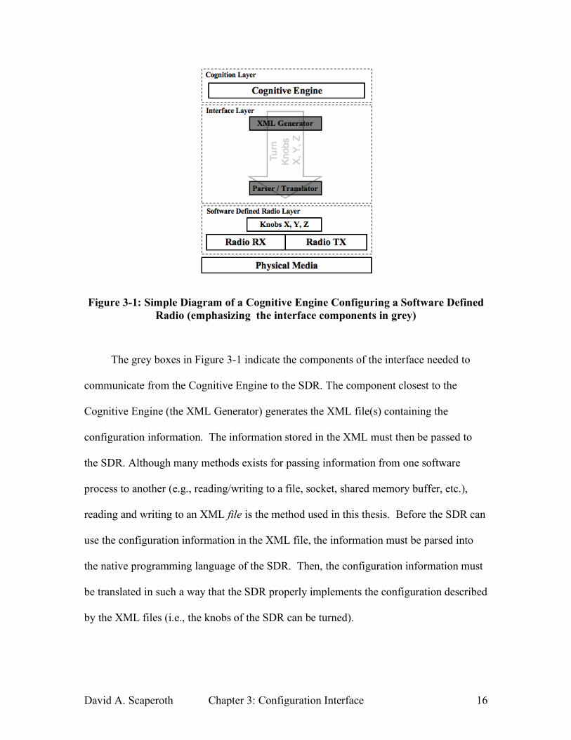
programming languages [19]. Figure 3-1 shows a CE communicating configuration
information for arbitrary SDR knobs (X, Y, Z) via XML to the SDR.
David A. Scaperoth Chapter 3: Configuration Interface 16
Figure 3-1: Simple Diagram of a Cognitive Engine Configuring a Software Defined Radio (emphasizing the interface components in grey)
The grey boxes in Figure 3-1 indicate the components of the interface needed to
communicate from the Cognitive Engine to the SDR. The component closest to the
Cognitive Engine (the XML Generator) generates the XML file(s) containing the
configuration information. The information stored in the XML must then be passed to
the SDR. Although many methods exists for passing information from one software
process to another (e.g., reading/writing to a file, socket, shared memory buffer, etc.),
reading and writing to an XML file is the method used in this thesis. Before the SDR can
use the configuration information in the XML file, the information must be parsed into
the native programming language of the SDR. Then, the configuration information must
be translated in such a way that the SDR properly implements the configuration described
by the XML files (i.e., the knobs of the SDR can be turned).
David A. Scaperoth Chapter 3: Configuration Interface 17
The purpose of this section is to explain the specific functions of the SDR XML
and how this SDR XML format could eventually be used for almost any SDR platform
that is communicating with the Cognitive Engine. Because this prototype is the first of its
kind, the initial format is limited and primitive; however, the structure of the SDR XML
is organized to allow for modifications and improvements to eventually make the design
a more general solution.
3.1 Software Defined Radio (SDR) XML files
Two types of SDR XML files are used to configure the SDR: SDR Definition XML
and SDR Behavior XML. The SDR Definition XML file describes all of the possible
configuration combinations that are capable within a specific SDR, and the SDR
Behavior XML file is a specific instance of one possible SDR configuration.
The SDR Definition XML file essentially limits the solution search space for the
CE. All SDR’s have limitations to their ability to change their configuration. Whether
the limitation is a finite set of center frequency bands (VHF or UHF), or an upper limit on
the power level of a transmitter, limitations exist in every radio. In order for the CE to
make reasonable choices about the configuration of the radio, information about the
SDR’s limitations must be given to the Cognitive Engine before the decision-making
process begins. The SDR Definition XML file(s) is generated and sent to the CE before
the decision-making process begins.
When the CE makes a decision about how to configure the radio, the SDR
Behavior XML is sent to the SDR. The SDR Behavior XML file(s) contain the values to
which the knobs will be turned in the radio.
David A. Scaperoth Chapter 3: Configuration Interface 18
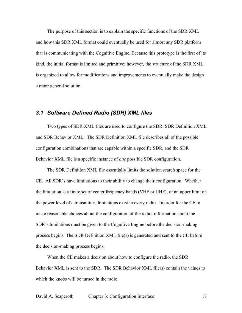
Figure 3-2: Simple Diagram of the Flow of XML Data to Configure an SDR
Figure 3-2 shows the relationship between the two types of SDR XML files and
the sequence where the two types of files are passed between the CE and the SDR. The
numbers (1) and (2) indicate their sequence of operation during the operation of the CR.
The SDR Behavior XML cannot be generated until the SDR Definition XML file(s) (in
Figure 3-2 it is abbreviated SDR Def. XML) has been given to the Cognitive Engine.
3.1.1 SDR XML Framework
Because the SDR Behavior XML file is a subset of the SDR Definition XML file,
making the two file types have a similar format/structure would be intuitive. This section
discusses the framework that is common to both types of SDR XML.
David A. Scaperoth Chapter 3: Configuration Interface 19
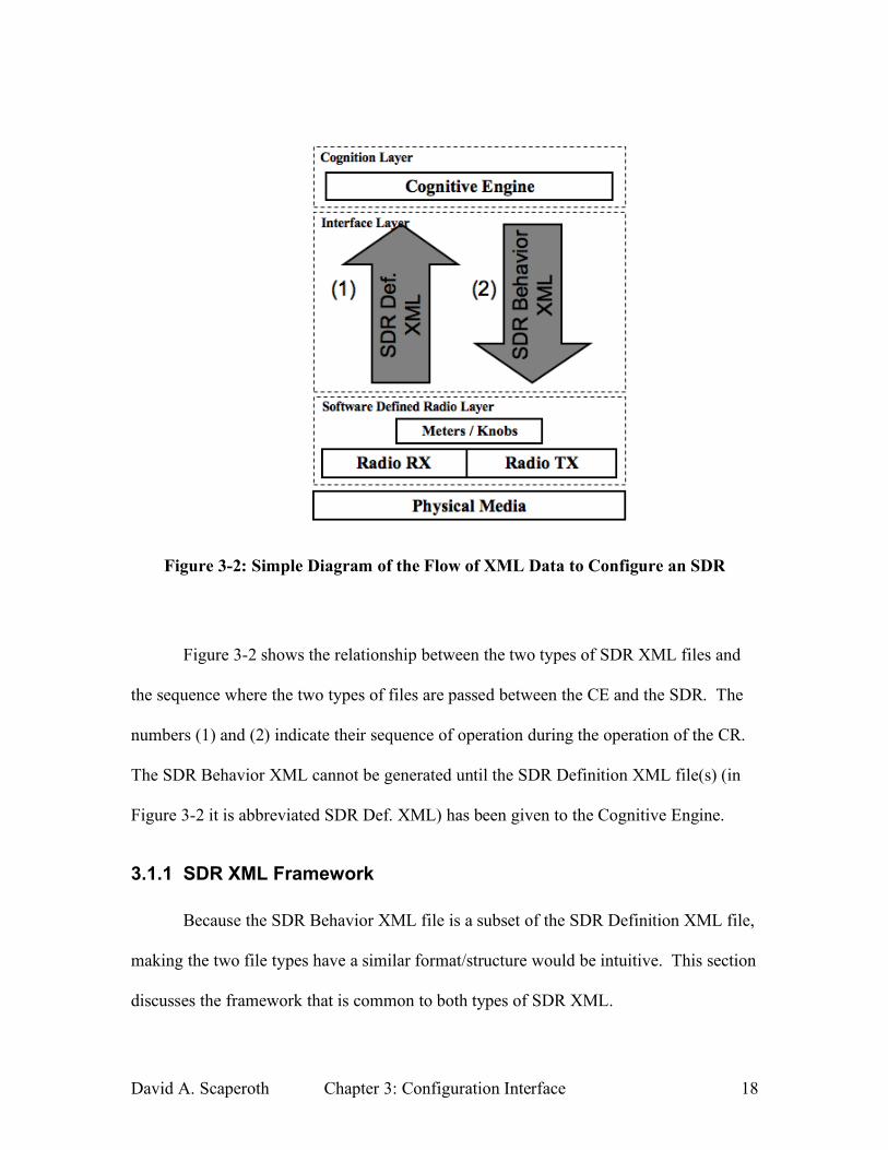
Since XML follows a hierarchical structure, the organization of the parameters of
the radio is composed of layers. The highest layer is called the radio layer, and it simply
contains any information about a specific SDR. In XML, the radio layer looks like the
following.
<radio>
(radio related information here)
</radio>
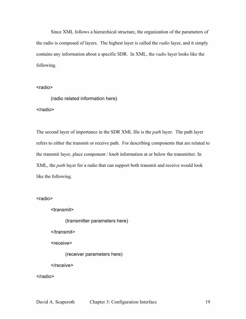
The second layer of importance in the SDR XML file is the path layer. The path layer
refers to either the transmit or receive path. For describing components that are related to
the transmit layer, place component / knob information at or below the transmitter. In
XML, the path layer for a radio that can support both transmit and receive would look
like the following.
<radio>
<transmit>
(transmitter parameters here)
</transmit>
<receive>
(receiver parameters here)
</receive>
</radio>
David A. Scaperoth Chapter 3: Configuration Interface 20
Some examples of transmit-specific information could be D/A sampling rate, transmit
power, transmit center frequency, etc. And a few examples of receiver-specific
information could be signal bandwidth, receiver gain, A/D rate, etc.
In the third layer, the Open Systems Interconnection (OSI) Model is used for
further organization of the transmitter and receiver information. For a system that used
components from the Physical (PHY) and Media Access Control (MAC) layers, the
structure may look like the following.
<radio>
<transmit>
<PHY>
(transmitter PHY parameters here)
</PHY>
<MAC>
(transmitter MAC parameters here)
</MAC>
</transmit>
<receive>
<PHY>
(receiver PHY parameters here)
</PHY>
<MAC>
David A. Scaperoth Chapter 3: Configuration Interface 21
(receiver MAC parameters here)
</MAC>
</receive>
</radio>
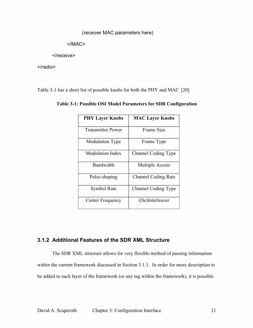
Table 3-1 has a short list of possible knobs for both the PHY and MAC [20].
Table 3-1: Possible OSI Model Parameters for SDR Configuration
PHY Layer Knobs MAC Layer Knobs
Transmitter Power Frame Size
Modulation Type Frame Type
Modulation Index Channel Coding Type
Bandwidth Multiple Access
Pulse-shaping Channel Coding Rate
Symbol Rate Channel Coding Type
Center Frequency (De)Interleaver
3.1.2 Additional Features of the SDR XML Structure
The SDR XML structure allows for very flexible method of passing information
within the current framework discussed in Section 3.1.1. In order for more description to
be added to each layer of the framework (or any tag within the framework), it is possible
David A. Scaperoth Chapter 3: Configuration Interface 22
to include XML attributes in the tags to provide more information about each layer. For
example, in the radio layer, it is possible to add information about the radio itself.
<radio name=”RF name here” other_info=”some numbers here”>
(radio related information here)
</radio>
In the above example, a tag is added to the radio name to provide information that could
be related to the RF Front-end, or a software package used, etc. The purpose of using the
XML attributes is to make each layer more descriptive.
The same could be true for the path layer. Additional attributes could be useful for
the path layer when using an SDR that has more than one transmit/receive path (in
MIMO devices) so that the transmit/receive paths would have to be distinguished by
some sort of identifier. For example, a device that used two independent transmit paths
could have the following form.
<radio>
<transmit id=”#1”>
(transmit #1 parameters here)
</transmit>
<transmit id=”#2”>
(transmit #2 parameters here)
David A. Scaperoth Chapter 3: Configuration Interface 23
</receive>
</radio>
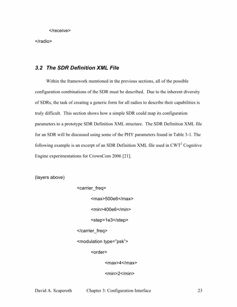
3.2 The SDR Definition XML File
Within the framework mentioned in the previous sections, all of the possible
configuration combinations of the SDR must be described. Due to the inherent diversity
of SDRs, the task of creating a generic form for all radios to describe their capabilities is
truly difficult. This section shows how a simple SDR could map its configuration
parameters to a prototype SDR Definition XML structure. The SDR Definition XML file
for an SDR will be discussed using some of the PHY parameters found in Table 3-1. The
following example is an excerpt of an SDR Definition XML file used in CWT2 Cognitive
Engine experimentations for CrownCom 2006 [21].
(layers above)
<carrier_freq>
<max>500e6</max>
<min>400e6</min>
<step>1e3</step>
</carrier_freq>
<modulation type=”psk”>
<order>
<max>4</max>
<min>2</min>
David A. Scaperoth Chapter 3: Configuration Interface 24
<step>pow(2,x)</step>
</order>
</modulation>
<filter type=”rrc”>
<factor>
<max>1.0</max>
<min>0.01</min>
<step>0.01</step>
</factor>
</filter>
(layers below)
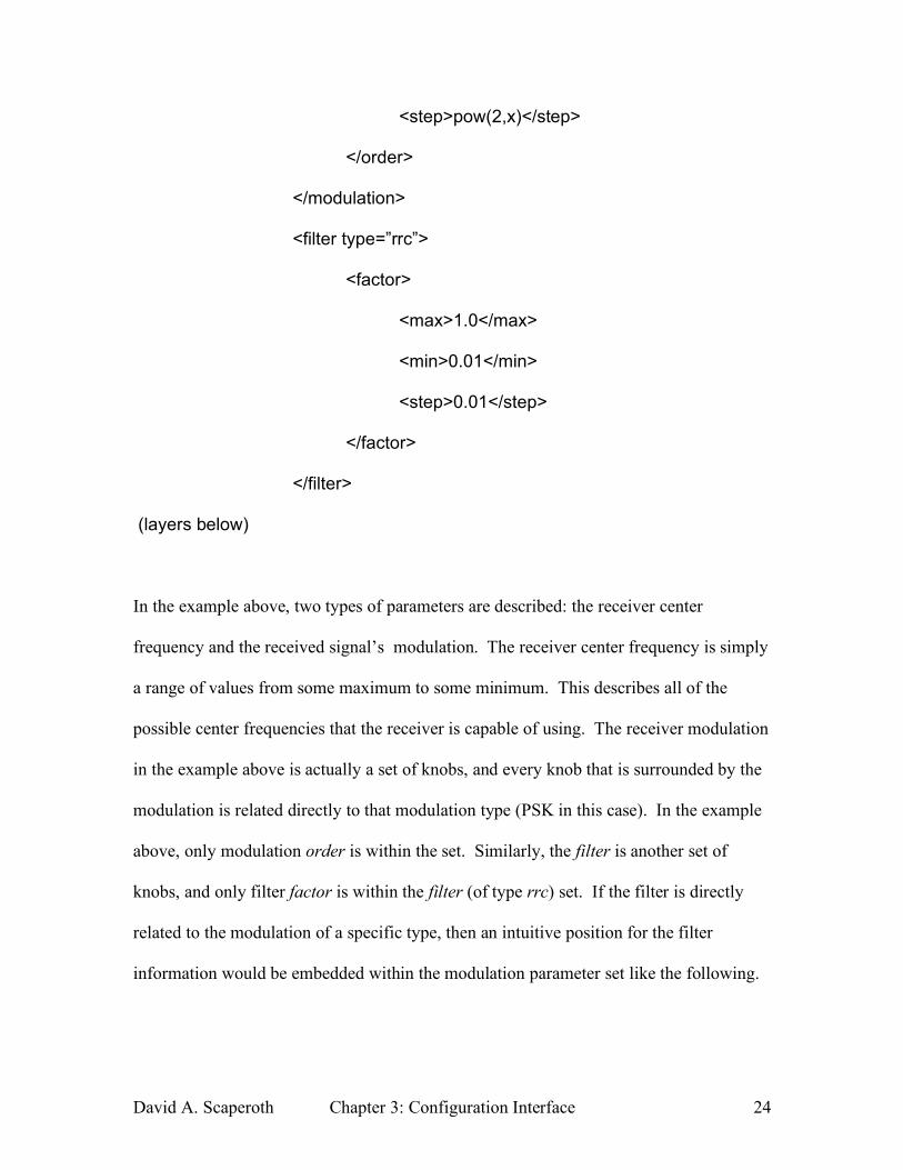
In the example above, two types of parameters are described: the receiver center
frequency and the received signal’s modulation. The receiver center frequency is simply
a range of values from some maximum to some minimum. This describes all of the
possible center frequencies that the receiver is capable of using. The receiver modulation
in the example above is actually a set of knobs, and every knob that is surrounded by the
modulation is related directly to that modulation type (PSK in this case). In the example
above, only modulation order is within the set. Similarly, the filter is another set of
knobs, and only filter factor is within the filter (of type rrc) set. If the filter is directly
related to the modulation of a specific type, then an intuitive position for the filter
information would be embedded within the modulation parameter set like the following.
David A. Scaperoth Chapter 3: Configuration Interface 25
(layers above)
<modulation type=”psk”>
<order>
<max>4</max>
<min>2</min>
<step>pow(2,x)</step>
</order>
<filter type=”rrc”>
<factor>
<max>1.0</max>
<min>0.01</min>
<step>0.01</step>
</factor>
</filter>
</modulation>
(layers below)
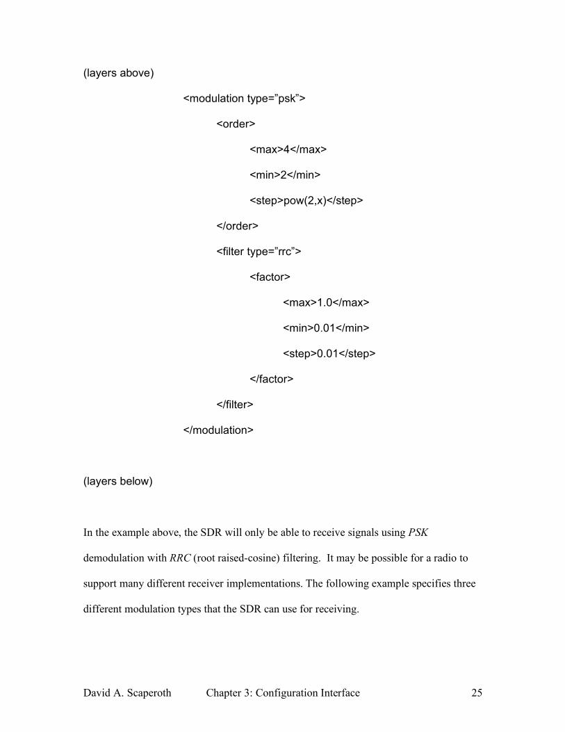
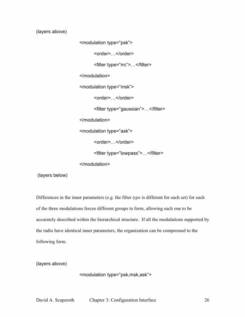
In the example above, the SDR will only be able to receive signals using PSK
demodulation with RRC (root raised-cosine) filtering. It may be possible for a radio to
support many different receiver implementations. The following example specifies three
different modulation types that the SDR can use for receiving.
David A. Scaperoth Chapter 3: Configuration Interface 26
(layers above)
<modulation type=”psk”>
<order>…</order>
<filter type=”rrc”>…</filter>
</modulation>
<modulation type=”msk”>
<order>…</order>
<filter type=”gaussian”>…</filter>
</modulation>
<modulation type=”ask”>
<order>…</order>
<filter type=”lowpass”>…</filter>
</modulation>
(layers below)
Differences in the inner parameters (e.g. the filter type is different for each set) for each
of the three modulations forces different groups to form, allowing each one to be
accurately described within the hierarchical structure. If all the modulations supported by
the radio have identical inner parameters, the organization can be compressed to the
following form.
(layers above)
<modulation type=”psk,msk,ask”>
David A. Scaperoth Chapter 3: Configuration Interface 27
<order>…</order>
<filter type=”rrc,gaussian,lowpass”>…</filter>
</modulation>
(layers below)
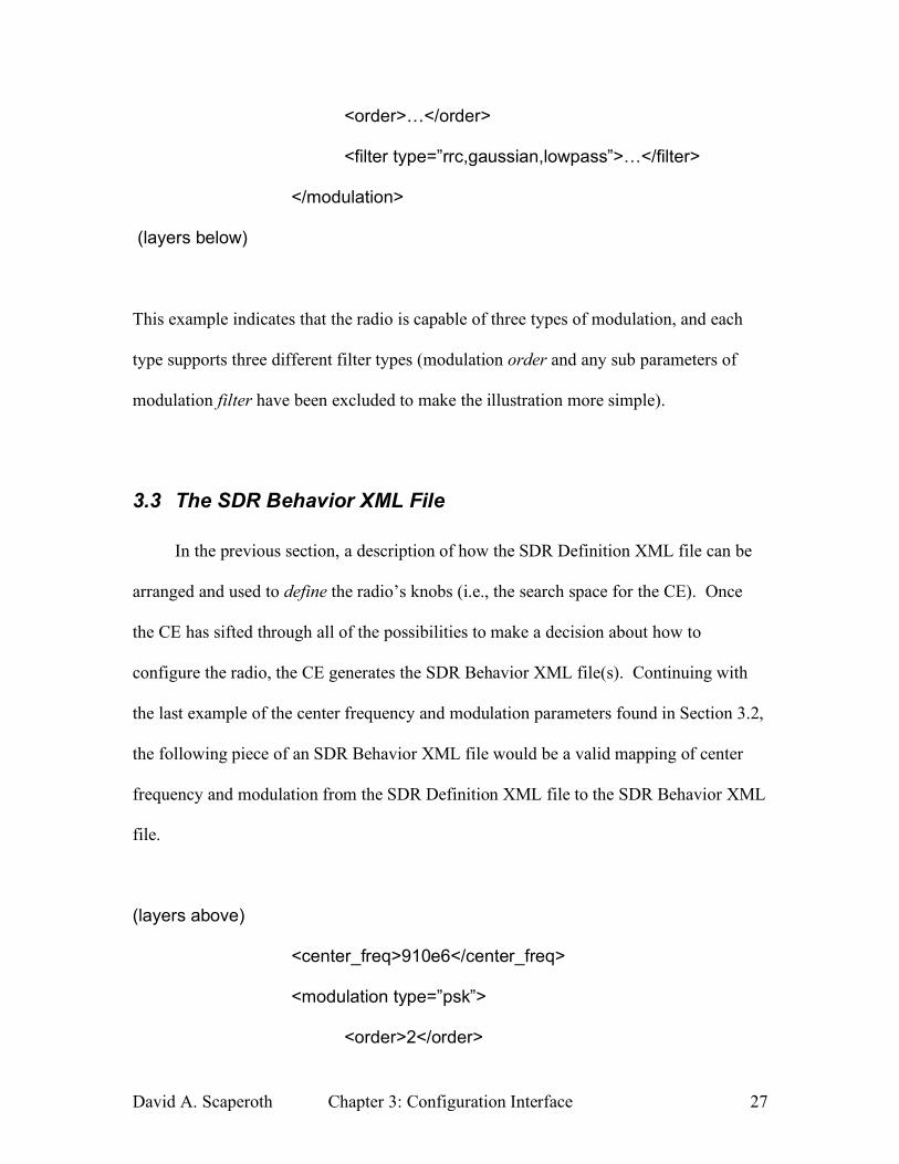
This example indicates that the radio is capable of three types of modulation, and each
type supports three different filter types (modulation order and any sub parameters of
modulation filter have been excluded to make the illustration more simple).
3.3 The SDR Behavior XML File
In the previous section, a description of how the SDR Definition XML file can be
arranged and used to define the radio’s knobs (i.e., the search space for the CE). Once
the CE has sifted through all of the possibilities to make a decision about how to
configure the radio, the CE generates the SDR Behavior XML file(s). Continuing with
the last example of the center frequency and modulation parameters found in Section 3.2,
the following piece of an SDR Behavior XML file would be a valid mapping of center
frequency and modulation from the SDR Definition XML file to the SDR Behavior XML
file.
(layers above)
<center_freq>910e6</center_freq>
<modulation type=”psk”>
<order>2</order>
David A. Scaperoth Chapter 3: Configuration Interface 28
<filter type=”rrc”>
<factor>0.25</factor>
</filter>
</modulation>
(layers below)
3.4 Passing the Behavior Data to the SDR
Once the SDR Behavior XML Data has been generated, the information must be
interpreted correctly by the SDR in order for the decisions of the CE to be effectively
utilized. Figure 3-1 shows the components in the translation process that are used to map
the knobs of the CE to drivers and/or modules that the SDR uses to control the arbitrary
knobs X, Y, Z.
One limitation of this interface is the SDR XML translator. The SDR XML
translator is transforming the information in the SDR Behavior XML file(s) into
information that the drivers and modules of the SDR can use. Unfortunately, the SDR
XML translator is inherently SDR dependent because of the diversity in the design of RF
architectures. Currently, RF hardware uses any number of devices (ASIC, FPGA, DSP,
etc.) to do signal processing, and this is an indication that peripheral control of any
software components within these signal processing devices will be different from radio
to radio.
David A. Scaperoth Chapter 4: Implementing the SDR XML Files 29
4 Implementing the SDR XML using
GNU Radio and the USRP
In Section 4, a system level description of how a CE can communicate with an SDR
is discussed; the GNU Radio and the USRP are used as the SDR platform for a proof-of-
concept example. To illustrate configuring the SDR, SDR XML files following the
framework discussed in Section 3 will be used to change the operation of the radio into
three specific implementations. These SDR XML files have been generated manually
instead of being generated in the CE. In order to focus on how an SDR can be configured
quickly using this interface, the operation of the Cognitive Engine and how its algorithms
are used to determine a configuration for a radio will not be discussed here; however,
Thomas Rondeau has done work to address how a CE can generate results similar to the
ones that follow in this chapter [21].
Based on the system level view of the interface from the CE to the SDR in Figure 3-
1, the Parser/Translator components are described for the GNU Radio and USRP
platform. The Parser reads the SDR Behavior XML into Python, and the Translator
maps the SDR Behavior XML parameters to GNU Radio Flow graphs. Finally, the three
example configurations and their test setup are discussed, along with some results of the
experiments.
David A. Scaperoth Chapter 4: Implementing the SDR XML Files 30
4.1 The Python XML Parser
The Python XML Parser component reads the XML into a Document Object
Model (DOM), which is formatted into a single Python object that describes the entire
SDR Behavior XML file(s). The parsing of the XML files into Python is done using a
standard Python XML package PyXML, which utilizes eXpat, a widely used open-source
XML parser [22]. The XML parsing that is done here is similar to the work done in the
Amara open-source software package [23].
The Python programming language is the native language of GNU Radio, and
thus, any and all information that is formatted into XML must be converted to Python
[24]. Python is an interpretive language that uses objects to manipulate data [25].
Depending on the type of object and its content, Python objects also have attributes. The
relationship between Python objects and their attributes is discussed further in order to
emphasize the similarities with XML’s hierarchical structure.
For example, a Python object might simply be called object_a, and object_a has
an attribute named attribute_of_object_a. This attribute can be a number, a string, a list,
etc. attribute_of_object_a can be accessed in Python using the following syntax.
object_a . attribute_of_object_a
An attribute can also contain attributes. For example attribute_of_object_a could have an
attribute named attribute_within_an_attribute, which could be accessed using the form.
object_a . attribute_of_object_a . attribute_within_an_attribute
David A. Scaperoth Chapter 4: Implementing the SDR XML Files 31
Clearly, Python objects and their Python attributes follow a structured,
hierarchical form, which can make mapping (or translating) XML information into
Python intuitive. In this paper, two different types of information are extracted from the
SDR Behavior XML files: XML text nodes and XML attributes. The following two
sections show the method for accessing both the XML text nodes and the XML attributes
from the SDR behavior XML file.
The XML text nodes are always enclosed between XML tags
(<tag>textnode</tag>), and in the case of the SDR Behavior XML files, XML text nodes
contain the value for each knob. The XML attributes are within the tag itself. For
example, the XML tag below has the attribute XMLattribute, and its value is
some_attribute_value (notice that this is all defined within the start tag (<tag>).
<tag XMLattribute = ”some_attribute_value”> </tag>)
In the SDR XML files, the XML attributes usually give secondary information about the
knobs or information about the general makeup of the radio.
An excerpt from an example SDR Behavior XML file is used in this section to
illustrate parsing both XML text nodes and XML attributes. Each of the parameters
within the SDR Behavior XML is contained within one Python object (in this case, the
base Python object will be called radio_obj), and each value found in the SDR Behavior
XML can be found as an attribute of radio_obj. For example, if the parameter desired is
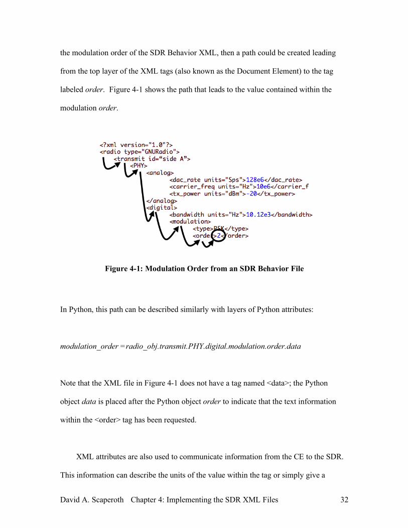
David A. Scaperoth Chapter 4: Implementing the SDR XML Files 32
the modulation order of the SDR Behavior XML, then a path could be created leading
from the top layer of the XML tags (also known as the Document Element) to the tag
labeled order. Figure 4-1 shows the path that leads to the value contained within the
modulation order.
Figure 4-1: Modulation Order from an SDR Behavior File
In Python, this path can be described similarly with layers of Python attributes:
modulation_order =radio_obj.transmit.PHY.digital.modulation.order.data
Note that the XML file in Figure 4-1 does not have a tag named <data>; the Python
object data is placed after the Python object order to indicate that the text information
within the <order> tag has been requested.
XML attributes are also used to communicate information from the CE to the SDR.
This information can describe the units of the value within the tag or simply give a
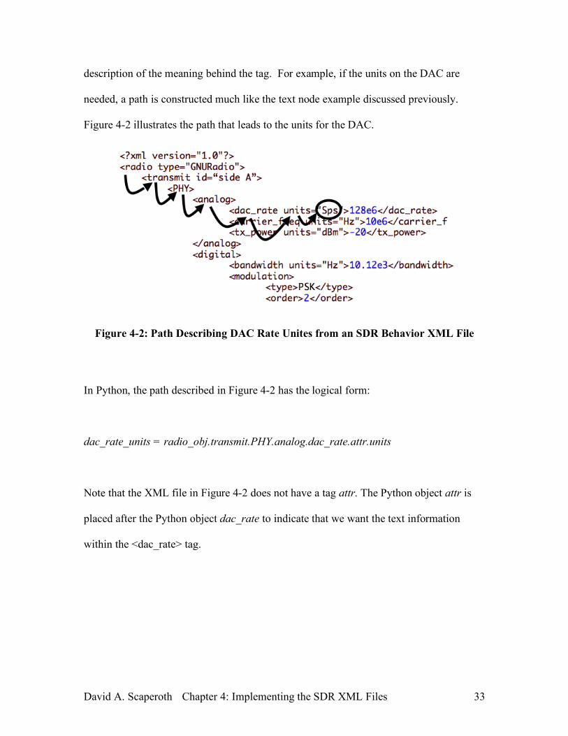
David A. Scaperoth Chapter 4: Implementing the SDR XML Files 33
description of the meaning behind the tag. For example, if the units on the DAC are
needed, a path is constructed much like the text node example discussed previously.
Figure 4-2 illustrates the path that leads to the units for the DAC.
Figure 4-2: Path Describing DAC Rate Unites from an SDR Behavior XML File
In Python, the path described in Figure 4-2 has the logical form:
dac_rate_units = radio_obj.transmit.PHY.analog.dac_rate.attr.units
Note that the XML file in Figure 4-2 does not have a tag attr. The Python object attr is
placed after the Python object dac_rate to indicate that we want the text information
within the <dac_rate> tag.
David A. Scaperoth Chapter 4: Implementing the SDR XML Files 34
4.2 The GNU Radio Translator
Once the SDR Behavior XML file information has been parsed into Python, the
information must be formatted to control the GNU Radio software and the USRP. Flow
graphs are the elements that are changed or modified based on the SDR Behavior XML
file. The GNU Radio flow graphs used in this paper are referred to as template flow
graphs because a single flow graph may handle many different configurations based upon
the content of the SDR Behavior XML file.
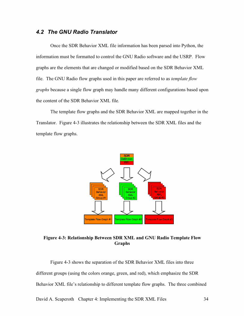
The template flow graphs and the SDR Behavior XML are mapped together in the
Translator. Figure 4-3 illustrates the relationship between the SDR XML files and the
template flow graphs.
Figure 4-3: Relationship Between SDR XML and GNU Radio Template Flow Graphs
Figure 4-3 shows the separation of the SDR Behavior XML files into three
different groups (using the colors orange, green, and red), which emphasize the SDR
Behavior XML file’s relationship to different template flow graphs. The three combined
David A. Scaperoth Chapter 4: Implementing the SDR XML Files 35
groups represent all of the possible SDR Behavior XML files that could be generated
using the SDR Definition file (for more information, see Section 3). Multiple SDR
Behavior XML files may be related to the same template flow graph because often the
SDR Behavior XML files are similar in content (e.g., if only the center frequency is
different between two SDR Behavior XML files, or the PGA gain is changed); however,
each SDR Behavior XML file cannot be related to more than one template flow graph
because the SDR Behavior XML file corresponds to a single implementation of the SDR.
If two template flow graphs are compatible with a single SDR Behavior XML file, then
one of the template flow graphs becomes redundant.
Although, Figure 4-3 illustrates a system with multiple template flow graphs
related to groups of SDR Behavior XML, it is conceivable that one template flow graph
could handle all of the possible configurations generated by the CE. The template flow
graph itself, however, would become significantly more complicated (depending on the
number of SDR Behavior XML files that are possible).
Instead, this discussion separates the template flow graphs based on two criteria
(occupied bandwidth and modulation) in order to simplify the design of the template flow
graphs. For example, a narrowband FM receiver would be a different template flow
graph than a wideband FM receiver, and an AM receiver/FM transmitter would be a
different template flow graph than an AM receiver/AM transmitter.
Each possible SDR Behavior XML file is mapped to a specific flow graph
template. Although, this mapping allows for easy configurability when the system is
running (the CE’s abilities are modified to allow for more expansive optimization that
involves controlling more parameters in the SDR) the template flow graphs would have
David A. Scaperoth Chapter 4: Implementing the SDR XML Files 36
to be changed to support the additional parameters. A remapping of the SDR XML
parameters to the flow graphs would have to be done to assure that all SDR Behavior
XML combinations would be accounted for in a unique template flow graph.
For example, if the CE was not previously capable of controlling the taps of the
filters within each GNU Radio flow graph, the template flow graph would assume the
values of the taps based upon other information about the system (e.g., bandwidth of a
modulated signal, sampling rate going to an audio card, etc.). If the CE, however, is
modified to control the exact values of the filter taps within the flow graph, the template
flow graph would have to be modified to be able to use the tap values that are given.
4.3 Example Implementation
In Chapter 3, the framework for the SDR XML files is discussed, and the example
in this section shows an implementation of the framework for use with simple radio
configurations designed for the GNU Radio & the USRP. Three configurations have
been created: wideband VHF FM receiver/narrowband VHF FM transmitter, narrowband
UHF FM receiver/wideband VHF FM transmitter, and narrowband UHF FM
receiver/narrowband VHF FM transmitter. Each of these configurations
transmits/receives analog voice, and the configurations can be quickly changed based
largely on the time to parse the SDR Behavior XML file. In each case, the voice/music
signal is demodulated to baseband before being upconverted. By separating the
demodulation and modulation operations, GNU Radio and the USRP are able to illustrate
an elementary interoperability solution.
David A. Scaperoth Chapter 4: Implementing the SDR XML Files 37
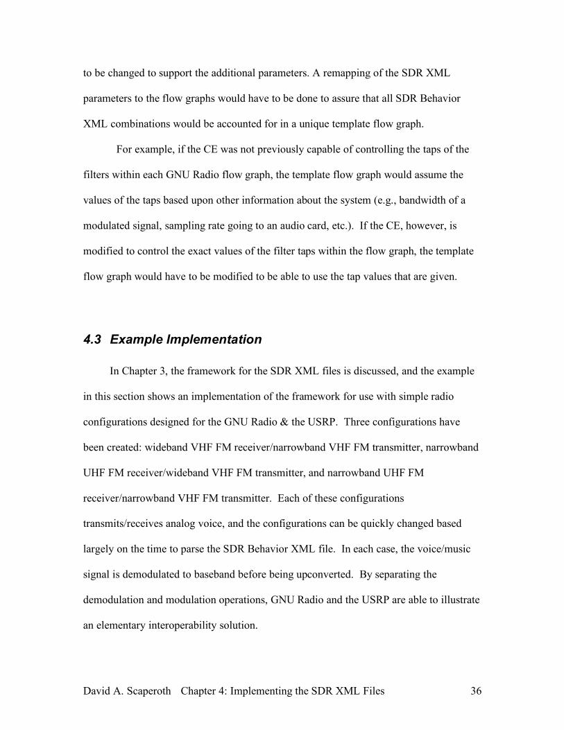
4.3.1 Wideband FM VHF Rx / Narrowband FM VHF Tx
The configuring the GNU Radio and the USRP for a wideband FM VHF signal
reception and narrowband FM VHF transmission is done with two the SDR Behavior
XML files (one for receiving and one for transmission). See Appendix A.1 and
Appendix A.4 for SDR Behavior XML files. In order to demonstrate the configuration
process, the wideband VHF FM receiver is tuned to a local radio station (105.3MHz), and
the narrowband VHF transmitter is tuned to a public safety radio channel (154MHz).
Figure 4-4 shows the test setup.
Figure 4-4: Demonstration Configuration VHF Wideband Rx / VHF Narrowband Tx with the USRP.
Photograph from Matt Ettus August 21, 2007 [27]
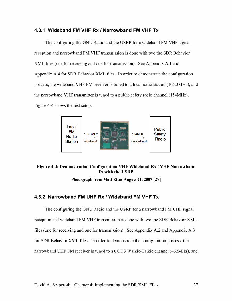
4.3.2 Narrowband FM UHF Rx / Wideband FM VHF Tx
The configuring the GNU Radio and the USRP for a narrowband FM UHF signal
reception and wideband FM VHF transmission is done with two the SDR Behavior XML
files (one for receiving and one for transmission). See Appendix A.2 and Appendix A.3
for SDR Behavior XML files. In order to demonstrate the configuration process, the
narrowband UHF FM receiver is tuned to a COTS Walkie-Talkie channel (462MHz), and
David A. Scaperoth Chapter 4: Implementing the SDR XML Files 38
the narrowband VHF transmitter is tuned to a broadcast FM channel (88MHz). Figure 4-5
shows the test setup.
Figure 4-5: Demonstration Configuration UHF Narrowband Rx / VHF Wideband Tx with the USRP.
Photograph from Matt Ettus August 21, 2007 [27]
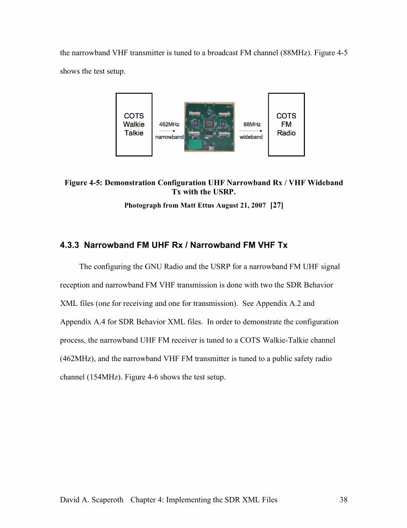
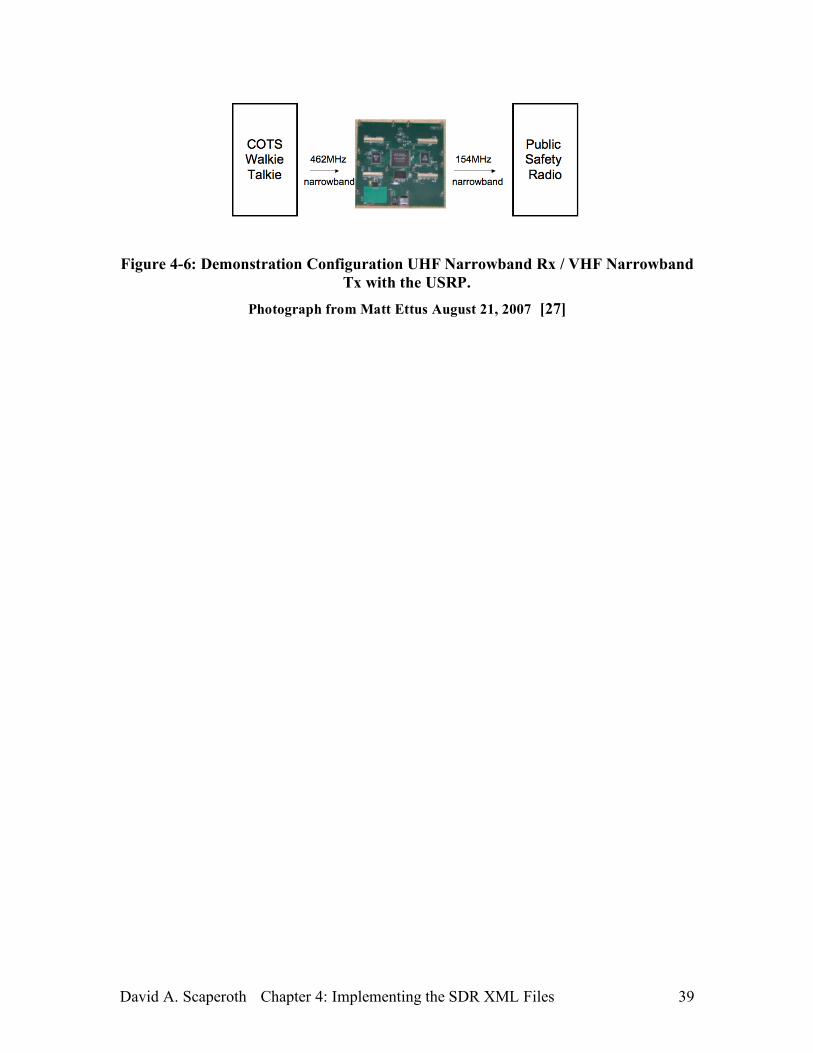
4.3.3 Narrowband FM UHF Rx / Narrowband FM VHF Tx
The configuring the GNU Radio and the USRP for a narrowband FM UHF signal
reception and narrowband FM VHF transmission is done with two the SDR Behavior
XML files (one for receiving and one for transmission). See Appendix A.2 and
Appendix A.4 for SDR Behavior XML files. In order to demonstrate the configuration
process, the narrowband UHF FM receiver is tuned to a COTS Walkie-Talkie channel
(462MHz), and the narrowband VHF FM transmitter is tuned to a public safety radio
channel (154MHz). Figure 4-6 shows the test setup.
David A. Scaperoth Chapter 4: Implementing the SDR XML Files 39
Figure 4-6: Demonstration Configuration UHF Narrowband Rx / VHF Narrowband Tx with the USRP.
Photograph from Matt Ettus August 21, 2007 [27]
David A. Scaperoth Chapter 5: Conclusions and Future Work 40
5 Conclusions and Future Work
A Cognitive Radio can be a powerful tool for configuring an SDR to interoperate
with many different types of radios (old and new). The Cognitive Engine and the SDR
are the most important components of the CR, and creating an effective method for
passing information between the two components is essential for cognitive control of the
SDR.
This thesis has begun the development of an XML format to allow a Cognitive
Engine to pass information to an SDR. Along with an XML format, a translator software
package has been created for the GNU Radio and the USRP SDR platform in order to
configure the radio using the XML passed in from a CE.
In the demonstrations described in sections 4.3.1, 4.3.2, 4.3.3, the GNU Radio and
USRP SDR are configured using the SDR XML files described in this thesis. The time to
configure the GUS is measured from the moment the XML is read, to the time the signal
appears in the spectrum. Over several iterations, the time to configure is approximately
0.7 seconds. Although the benchmark proves to configure the radio at push-to-talk
speeds, significant optimization could be done to improve its performance by two or three
fold. The process of reading in an XML file is the largest source of latency, and many
options can replace the computationally expensive task of opening and reading a file.
For example, the DOM could be sent over a TCP socket or shared memory.
David A. Scaperoth Chapter 5: Conclusions and Future Work 41
This thesis primarily focuses on only passing configuration information from the
CE to the SDR, however, a fully operable CR must be able to pass many different types
of information in both directions continuously because of the real-time nature of the
system. Also, the expensive process of reading and writing XML files can lead to
significant latency, which should be improved in order for the system to operate more
efficiently in real-time.
Another area of future work includes development of the SDR XML examples.
Some of the work that is still yet to be done to fully realize this Cognitive Radio system
includes creating an SDR XML format that includes a more complete set of SDR
parameters from all layers of the OSI stack.
David A. Scaperoth Appendix A: SDR XML Demo Files 42
Appendix A: SDR Behavior XML Demo
Files
This appendix shows examples of the four SDR Behavior XML files used for
demonstrations in Sections 4.3.1, 4.3.2, and 4.3.3.
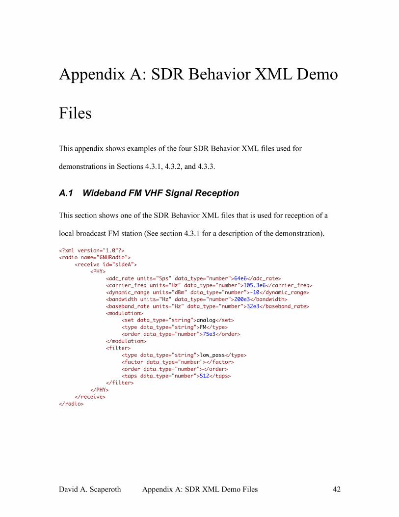
A.1 Wideband FM VHF Signal Reception
This section shows one of the SDR Behavior XML files that is used for reception of a
local broadcast FM station (See section 4.3.1 for a description of the demonstration).
<?xml version="1.0"?> <radio name="GNURadio"> <receive id="sideA"> <PHY> <adc_rate units="Sps" data_type="number">64e6</adc_rate> <carrier_freq units="Hz" data_type="number">105.3e6</carrier_freq> <dynamic_range units="dBm" data_type="number">-10</dynamic_range> <bandwidth units="Hz" data_type="number">200e3</bandwidth> <baseband_rate units="Hz" data_type="number">32e3</baseband_rate> <modulation> <set data_type="string">analog</set> <type data_type="string">FM</type> <order data_type="number">75e3</order> </modulation> <filter> <type data_type="string">low_pass</type> <factor data_type="number"></factor> <order data_type="number"></order> <taps data_type="number">512</taps> </filter> </PHY> </receive> </radio>
David A. Scaperoth Appendix A: SDR XML Demo Files 43
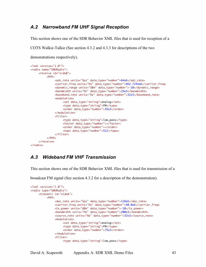
A.2 Narrowband FM UHF Signal Reception
This section shows one of the SDR Behavior XML files that is used for reception of a
COTS Walkie-Talkie (See section 4.3.2 and 4.3.3 for descriptions of the two
demonstrations respectively).
<?xml version="1.0"?> <radio name="GNURadio"> <receive id="sideB"> <PHY> <adc_rate units="Sps" data_type="number">64e6</adc_rate> <carrier_freq units="Hz" data_type="number">462.7244e6</carrier_freq> <dynamic_range units="dBm" data_type="number">-10</dynamic_range> <bandwidth units="Hz" data_type="number">25e3</bandwidth> <baseband_rate units="Hz" data_type="number">32e3</baseband_rate> <modulation> <set data_type="string">analog</set> <type data_type="string">FM</type> <order data_type="number">35e3</order> </modulation> <filter> <type data_type="string">low_pass</type> <factor data_type="number"></factor> <order data_type="number"></order> <taps data_type="number">512</taps> </filter> </PHY> </receive> </radio>
A.3 Wideband FM VHF Transmission
This section shows one of the SDR Behavior XML files that is used for transmission of a
broadcast FM signal (See section 4.3.2 for a description of the demonstration).
<?xml version="1.0"?> <radio type="GNURadio"> <transmit id="sideA"> <PHY> <dac_rate units="Sps" data_type="number">128e6</dac_rate> <carrier_freq units="Hz" data_type="number">40.0e6</carrier_freq> <tx_power units="dBm" data_type="number">-10</tx_power> <bandwidth units="Hz" data_type="number">200e3</bandwidth> <source_rate units="Hz" data_type="number">32e3</source_rate> <modulation> <set data_type="string">analog</set> <type data_type="string">FM</type> <order data_type="number">75e3</order> </modulation> <filter> <type data_type="string">low_pass</type>
David A. Scaperoth Appendix A: SDR XML Demo Files 44
<factor data_type="number"></factor> <order data_type="number"></order> <taps data_type="number">512</taps> </filter> </PHY> </transmit> </radio>
A.4 Narrowband VHF FM Transmission
This section shows one of the SDR Behavior XML files that is used for transmission of a
public safety FM signal (See section 4.3.1 and 4.3.3 for descriptions of the two
demonstrations respectively).
<?xml version="1.0"?> <radio name="GNURadio"> <transmit id="sideA"> <PHY> <dac_rate units="Sps" data_type="number">128e6</dac_rate> <carrier_freq units="Hz" data_type="number">26.265e6</carrier_freq> <tx_power units="dBm" data_type="number">-10</tx_power> <bandwidth units="Hz" data_type="number">55e3</bandwidth> <source_rate units="Hz" data_type="number">32e3</source_rate> <modulation> <set data_type="string">analog</set> <type data_type="string">FM</type> <order data_type="number">25e3</order> </modulation> <filter> <type data_type="string">low_pass</type> <factor data_type="number"></factor> <order data_type="number"></order> <taps data_type="number">512</taps> </filter> </PHY> </transmit> </radio>
David A. Scaperoth Bibliography 45
Bibliography [1]. J. Mitola, G. Maguire, Telesystems Conference, 1992, NTC-92, Washington D.C.
19-20 May 1992, pp. 13/15 – 13/25.
[2]. J. Reed, Software Radio: A Modern Approach to Radio Engineering. Prentice Hall,
2002.
[3]. J. Mitola and G. Maguire, “Cognitive radio: Making software radios more
personal,” IEEE Personal Commun. Mag., vol. 6, no. 4, pp. 13–18, Aug. 1999.
[4]. J. Mitola III, "Cognitive radio: an integrated agent architecture for software defined
radio," Ph.D. dissertation, Computer Communication System Laboratory,
Department of Teleinformatics, Royal Institute of Technology (KTH), Stockholm,
Sweden, May 2000.
[5]. Ettus Research LLC, Homepage, [Online]. Available: http://www.ettus.com.
[Accessed September 7, 2007].
[6]. L. Patton, “A GNU Radio Based Software Defined Radar”. Master’s Thesis. Wright
State University, 2007. [Online]. Permission for use given by Lee Patton on August
18, 2007. Available: http://www.pattoncentral.org/gnuradio/diagram/. [Accessed
September 7, 2007].
[7]. Edgewall Software, “USRP FPGA”, GNU Radio, Free Software Foundation, 2007.
[Online]. Available: http://gnuradio.org/trac/wiki/UsrpFPGA. [Accessed September
7, 2007].
[8]. E. Blossom, “Exploring GNU Radio”, Free Software Foundation, 2007. [Online].
Available: http://www.gnu.org/software/gnuradio/doc/exploring-
David A. Scaperoth Bibliography 46
gnuradio.html#usrp. [Accessed September 7, 2007].
[9]. J. Gilmore, “HDTV and the USRP,” list.gnu.org, Free Software Foundation, 2007.
[Online]. Available: http://lists.gnu.org/archive/html/discuss-gnuradio/2004-
07/msg00034.html. [Accessed September 7, 2007].
[10]. E. Blossom, “GNU Radio – The GNU Software Radio,” Free Software Foundation,
2007. [Online]. Available: http://www.gnu.org/software/gnuradio. [Accessed
September 7, 2007].
[11]. BBN Technologies Group, “GNU Radio Architectural Changes,” BBN
Technologies, 2006. [Online]. Available:
http://acert.ir.bbn.com/downloads/adroit/gnuradio-architectural-enhancements-
3.pdf. [Accessed September 7, 2007].
[12]. Testbed Operations, “Emulab – Network Emulation,” The University of Utah,
2007. [Online]. Available: http://www.emulab.net. [Accessed September 7, 2007]
[13]. Balister, P., M. Robert, J. Reed, ''Impact of the use of CORBA for Inter-Component
Communication in SCA Based Radio,'' SDR Forum Technical Conference, Orlando
FL, Nov. 13-17, 2006. Session 1.1-4.
[14]. Dhar, Rahul; Steenkiste, Peter, “Supporting Integrated MAC and PHY Software
Development for the USRP SDR”. IEEE Workshop on Networking Technologies
for Software Defined Radio (SDR) Networks. Restin, VA, Sept. 25, 2006. Session
3-3.
[15]. Kohler, “The Click Modular Router Project”. [Online]. Available:
http://pdos.csail.mit.edu/click/. [Accessed September 7, 2007].
[16]. Ginsberg, A., Poston, J., and Horne, W., '' Toward a Cognitive Radio Architecture:
David A. Scaperoth Bibliography 47
Integrating Knowledge Representation with Software Defined Radio Technologies,''
MILCOM 2006, Washington DC, Oct. 23-25, 2006. Session US-T-U.
[17]. Nolan, K., Rondeau, T.W., Sutton, P.D., Bostian, C.W., Doyle, L.E., “A
Framework for Implementing Cognitive Functionality”, SDR Forum Technical
Conference, Orlando FL, Nov. 13-17, 2006. Session 3.5-5.
[18]. Stuntebeck, E., O’Shea, T., Hecker J., Clancy, T. Charles, “Architecture for an
Open-Source Cognitive Radio”, SDR Forum Technical Conference, Orlando FL,
Nov. 13-17, 2006. Session 3.6-5.
[19]. O’Reilly Media Inc., “XML Parsers,” 2007. [Online]. Available:
http://www.xml.com/pub/rg/XML_Parsers. [Accessed September 7, 2007].
[20]. The information for this table was taken from a document updated by Tom
Rondeau, the Center for Wireless Telecommunications at Virginia Tech, for a
meeting with Innovative Wireless Technologies (IWT) in a discussion about the
potential knobs and meters controlled by the CWT3 Cognitive Radio.
[21]. T. W. Rondeau, B. Le, D. Maldonado, D. Scaperoth, and C. W. Bostian, “Cognitive
Radio Formulation and Implementation,” IEEE Proc. CROWNCOM, Mykonos,
Greece, 2006. Invited Paper.
[22]. Sourceforge, Inc., “The Expat XML Parser”, 2007. [Online]. Available:
http://expat.sourceforge.net/. [Accessed September 7, 2007].
[23]. U. Ogbuji, “Amara XML Toolkit”, Creative Common License. [Online]. Available:
http://uche.ogbuji.net/tech/4suite/amara/. [Accessed September 7, 2007].
[24]. Python Software Foundation, Homepage. [Online]. Available:
http://www.python.org/. [Accessed September 7, 2007].
David A. Scaperoth Bibliography 48
[25]. M. Pilgrim, “Dive Into Python: Python from Novice to Pro”, May 4, 2004. [Online].
Available:
http://diveintopython.org/getting_to_know_python/everything_is_an_object.html.
[Accessed September 7, 2007].
[26]. Project 25, “What Is Project 25?”, Frequently Asked Questions, Jelsoft Enterprises
Ltd. 2000. [Online]. Available:
http://project25.org/Forum/faq.php?faq=faq_ptig#faq_p25_what_is. [Accessed
September 7, 2007].
[27]. Ettus Research LLC, Homepage, The figure’s objects are used with permission
given by Matt Ettus on August 21, 2007. [Online]. Available:
http://www.ettus.com/,. [Accessed September 7, 2007].
David A. Scaperoth Vita 48
Vita David Scaperoth grew up in Knoxville, TN, and attended the University of Tennessee,
Knoxville in the fall of 2000. David was active in the campus IEEE organization, and
became treasurer in the fall of 2004. As the treasurer, David help to organize and fund a
rebuilding project of the ECE student lounge in Ferris Hall, which was complete in the
spring of 2005. While he was at the University of Tennessee, David took part in a 3-term
co-op in Clearwater, Florida with the Guidance and Navigation group at Honeywell Corp.
There, David was apart of a group working on the Joint Strike Fighter (JSF) project.
During his three terms at Honeywell, David receive three commodations for his work on
the job. In May of 2005, David graduated from the University of Tennessee with a
Bachelor of Science in Electrical Engineering. After graduation, David attended Virginia
Tech as a Master’s student under Dr. Charles Bostian. As a GRA, David and the Center
for Wireless Telecommunications published four conference papers from the fall of 2005
to summer of 2006 on topics including cognitive radio, software defined radio, and GNU
Radio and the USRP. His areas of interest include software defined radio, cognitive
radio, and wireless technology.