Embed Size (px)
Citation preview
975-0717-01-01 Revision A04-2014 1
Contact Informationwww.schneider-electric.comPlease contact your local Schneider Electric Sales Representative or visit the Schneider Electric website at:http://www.SEsolar.com
www.SEsolar.comConext System Control Panel Installation Guide865-1050-01
Installer Provided Tools and Materials:• Phillips head screwdriver• Jigsaw or small keyhole saw• Cable clamps or hardware fasteners• Power drill with 1/8" bit (optional)
Xanbus cable
This Guide is intended for anyone who needs to operate, configure, and troubleshoot the Conext System Control Panel (SCP). Certain configuration tasks should only be performed by qualified personnel in consultation with your local utility and/or an authorized dealer. Electrical equipment should be installed, operated, serviced, and maintained only by qualified personnel. Servicing of batteries must only be performed or supervised by qualified personnel with knowledge of batteries and their required precautions. Qualified personnel have training, knowledge, and experience in:• Installing electrical equipment• Applying applicable installation codes• Analyzing and reducing the hazards involved in performing electrical work• Installing and configuring batteries• Selecting and using Personal Protective Equipment (PPE)No responsibility is assumed by Schneider Electric for any consequences arising out of the use of this material.
B Materials List
Mounting template sticker
Mounting plate forflush mounting
Network terminator
4 x #6 (M3) self-tapping screws
2 x #8 (M4) self-tapping screws
Mounting bracket for surface mounting
StandbyEvent/Warning
Conext SCP
System Control Panel (SCP)
MOUNTING TEMPLATE
FOR SURFACE MOUNTING:A) MARK LOCATIONS FOR MOUNTING SCREWSB) DRILL 1.375" (35mm) HOLE FOR COMMUNICATION CABLES
FOR FLUSH MOUNTING, CUT ALONG DASHED LINESCUTOUT SIZE: 6" X 4" (152.4mm x 101.3mm)
StandbyEvent/Warning
Conext SCP
• Selects a menu item• Displays the next screen
Standby
• Scrolls up a line of text• Increases a selected value• Displays the previous device home screen
• Scrolls down a line of text• Decreases a selected value• Displays the next device home screen
• Cancels selection of a menu item• Displays the previous screen
• Disables inverting and charging on all inverter/chargers in the system when pressed for one to two seconds.
To configure device settings
To display device statusIn the System Status screen, press down arrow to display device Home screens. The inverter/charger is the first Home screen by default.
Select Device
System Settings
XW-MPPT60-150
XW SCP
XW6848 00
setup system
XW6848 00:HomeStatusBatteryLoadAC1
Invert-26.4A 51.9V
1250W0.0V 0W
In the System Status screen, press Enter to display the Select Device screen.
HAZARD OF ELECTRIC SHOCK, EXPLOSION, OR ARC FLASH• Apply appropriate personal protective equipment (PPE) and follow safe electrical work practices. See NFPA 70E
or CSA Z462.• This equipment must only be installed and serviced by qualified electrical personnel. • Never operate energized with covers removed• Energized from multiple sources. Before removing covers identify all sources, de-energize, lock-out, and tag-out
and wait 2 minutes for circuits to discharge• Always use a properly rated voltage sensing device to confirm all circuits are de-energized.Failure to follow these instructions will result in death or serious injury.
DANGER
HAZARD OF ELECTRIC SHOCK, EXPLOSION, OR ARC FLASHBatteries can present a risk of electric shock and high short-circuit current. The following precautions must be observed when working with batteries:• Remove watches, rings or other metal objects.• Use tools with insulated handles.• Wear protective glasses, gloves and boots.• Do not lay tools or other metal parts on top of batteries.• Disconnect the charging source prior to connecting or disconnecting battery terminals.Failure to follow these instructions will result in death or serious injury.HAZARD OF ELECTRIC SHOCK, EXPLOSION, OR ARC FLASH• Battery Circuit Breakers must be installed according to the specifications and requirements specified by
Schneider Electric.• Servicing of batteries must only be performed by qualified personnel and the required precautions. Keep
unqualified personnel away from batteries.Failure to follow these instructions will result in death or serious injury.
A Important Safety Information
1. Before using the SCP, read all instructions and cautionary markings on the unit and all appropriate sections of this manual.
2. Use of accessories not recommended or sold by the manufacturer may result in a risk of fire, electric shock, or injury to persons.
3. The SCP is designed to be permanently connected to the Xanbus network. The manufacturer recommends that all wiring be done by a certified technician or electrician to ensure adherence to the local and national electrical codes applicable in your jurisdiction.
4. To avoid a risk of fire and electric shock, make sure that existing wiring is in good condition and that wire is not undersized. Do not operate the SCP with damaged or substandard wiring.
5. Do not operate the SCP if it has been damaged in any way.6. This unit does not have any user-serviceable parts. Do not disassemble the SCP except where noted for
connecting wiring and cabling. See your warranty for instructions on obtaining service. Attempting to service the unit yourself may result in a risk of electrical shock or fire. Internal capacitors remain charged after all power is disconnected.
7. To reduce the risk of electrical shock, disconnect connections from the SCP before attempting any maintenance or cleaning or working on any components connected to the SCP. Putting the unit in Standby mode will not reduce this risk.
8. Do not expose this unit to rain, snow, or liquids of any type. This product is designed for indoor use only. Damp environments will significantly shorten the life of this product and corrosion caused by dampness will not be covered by the product warranty.
9. To reduce the chance of short-circuits, always use insulated tools when installing or working with this equipment.10. Remove personal metal items such as rings, bracelets, necklaces, and watches when working with electrical
equipment.
DANGER indicates a hazardous situation which, if not avoided, will result in death or serious injury.
DANGER
WARNING indicates a hazardous situation which, if not avoided, could result in death or serious injury.
WARNING
CAUTION indicates a hazardous situation which, if not avoided, could result in minor or moderate injury.
CAUTION
NOTICE is used to address practices not related to physical injury.. The safety alert symbol shall not be used with this signal word.
NOTICE
A Important Safety InformationRead and Save These Instructions - Do Not DiscardThis guide contains important safety instructions for the Conext System Control Panel that must be followed during installation procedures. Read and keep this Quick Start Guide for future reference. Read these instructions carefully and look at the equipment to become familiar with the device before trying to install, operate, service or maintain it. The following special messages may appear throughout this bulletin or on the equipment to warn of potential hazards or to call attention to information that clarifies or simplifies a procedure.
The addition of either symbol to a “Danger” or “Warning” safety label indicates that an electrical hazard exists which will result in personal injury if the instructions are not followed.
This is the safety alert symbol. It is used to alert you to potential personal injury hazards. Obey all safety messages that follow this symbol to avoid possible injury or death.
Exclusion for DocumentationUNLESS SPECIFICALLY AGREED TO IN WRITING, SELLER
(A) MAKES NO WARRANTY AS TO THE ACCURACY, SUFFICIENCY OR SUITABILITY OF ANY TECHNICAL OR OTHER INFORMATION PROVIDED IN ITS MANUALS OR OTHER DOCUMENTATION;
(B) ASSUMES NO RESPONSIBILITY OR LIABILITY FOR LOSSES, DAMAGES, COSTS, OR EXPENSES, WHETHER SPECIAL, DIRECT, INDIRECT, CONSEQUENTIAL OR INCIDENTAL, WHICH MIGHT ARISE OUT OF THE USE OF SUCH INFORMATION. THE USE OF ANY SUCH INFORMATION WILL BE ENTIRELY AT THE USER’S RISK, AND
(C) REMINDS YOU THAT IF THIS MANUAL IS IN ANY LANGUAGE OTHER THAN ENGLISH, ALTHOUGH STEPS HAVE BEEN TAKEN TO MAINTAIN THE ACCURACY OF THE TRANSLATION, THE ACCURACY CANNOT BE GUARANTEED, APPROVED CONTENT IS CONTAINED WITH THE ENGLISH LANGUAGE VERSION WHICH IS POSTED AT WWW.SCHNEIDER-ELECTRIC.COM.
StandbyEvent/Warning
Conext SCP
C Using the System Control Panel – Basics
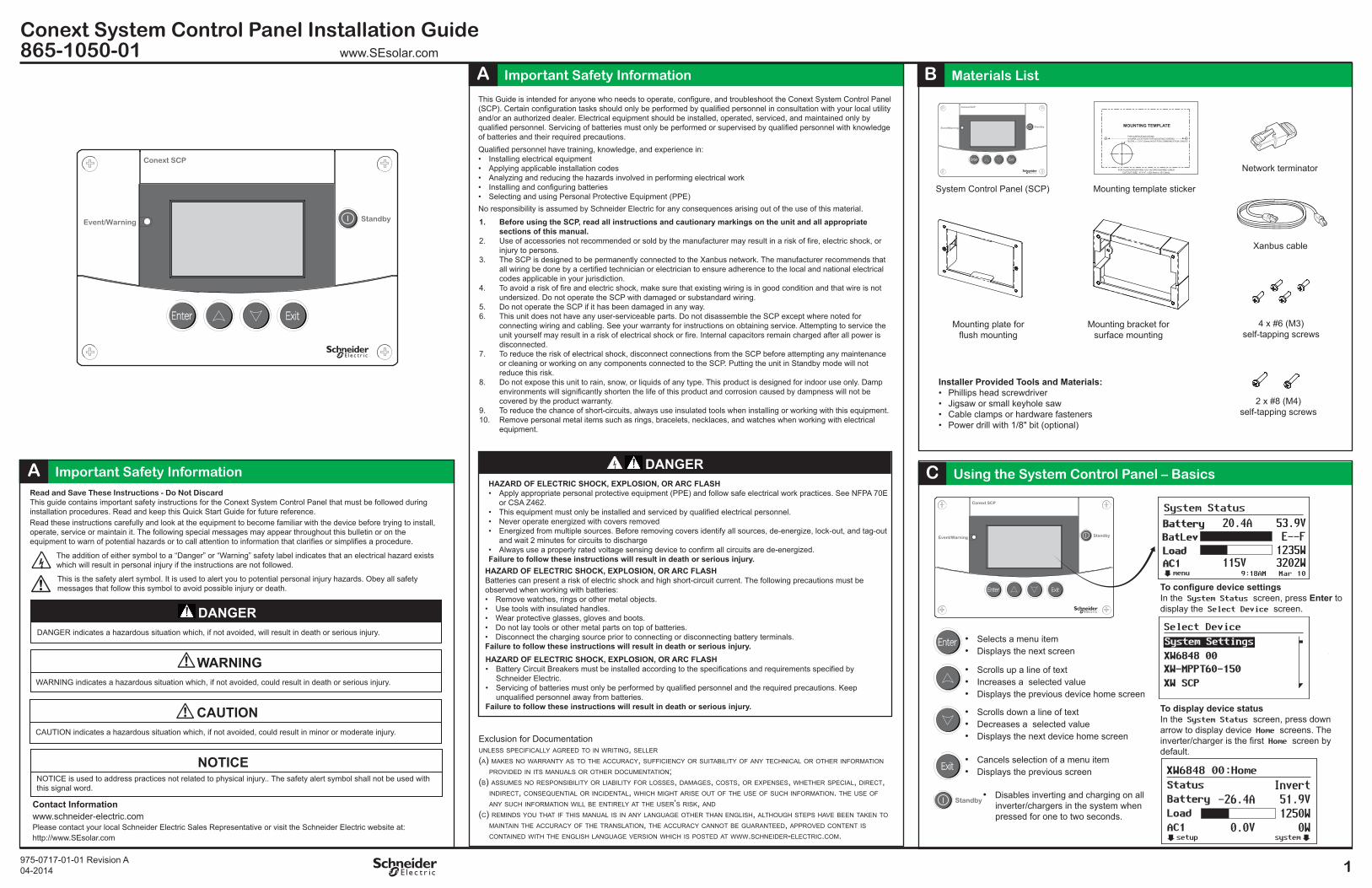
System Status
menu
Battery 20.4A 53.9V
AC1 115V 3202W
BatLev E--FLoad 1235W
9:18AM Mar 10

2Copyright © 2014 Schneider Electric. All Rights Reserved. All trademarks are owned by Schneider Electric Industries SAS or its affiliated companies.
www.SESolar.comConext System Control Panel Installation Guide
865-1050-01D Connecting Xanbus Cables
SHORT CIRCUIT OF NETWORK COMPONENTS• This network is not an ethernet system. Only connect Xanbus-enabled devices to other Xanbus-enabled devices.
Do not attempt to connect Xanbus-enabled devices to other networks or systems.• Ethernet crossover cables are not compatible with the Xanbus system. Use Category 5 (CAT 5 or CAT 5e) cables
to connect Xanbus-enabled devices.• Do not install network terminators in an AC Sync port. Failure to follow these instructions can result in damage to equipment.
NOTICE
XANBUS SHOCK HAZARDXanbus cables in contact with DC or AC power can transmit an electric shock.Do not route the Xanbus cables in the same conduit or panel as the AC and DC power cabling.Failure to follow these instructions can result in death or serious injury.
WARNING
Xanbus cables are connected to the SCP at the time the SCP is mounted.
Connecting Xanbus cables to the SCP1. Connect the Xanbus cable (or two Xanbus cables if the SCP is located between two
Xanbus-enabled devices) to a Xanbus network input in the SCP.2. Route and connect the cable(s) to the nearest Xanbus-enabled device(s).3. For additional devices, continue connecting cable as described above.4. Ensure the factory-supplied male network terminators are inserted into the empty inputs
in the Xanbus-enabled devices at the beginning and end of the network. When the network is completely connected, there should be no empty network inputs in any Xanbus-enabled device.
IGNITION AND FIRE HAZARD• This equipment is not ignition protected. To prevent fire or explosion, do not install this product in locations that
require ignition-protected equipment. This includes any confined space containing vented batteries, or flammable chemicals such as, natural gas (NG), liquid petroleum gas (LPG) or gasoline (Benzine/Petrol).
• Do not install in a confined space with machinery powered by flammable chemicals, or storage tanks, fittings, or other connections between components of fuel or flammable chemical systems.
• Do not install the SCP near readily flammable materials such as cloth, paper, straw, or plastic sheeting. Keep flammable materials a minimum distance of 600 cm (24 in.) from the top surface and 30 cm (12 in.) from either side surface and the front of the SCP.
Failure to follow these instructions can result in death or serious injury.
WARNING
For detailed instructions on installing the Xanbus network, see the Conext System Control Panel Owner’s Guide.
E Wall Mounting the System Control Panel
Flush mount the SCP using the mounting plate
1. Using a jigsaw and the supplied template sticker as a guide, cut out the hole for the mounting plate. The mount-ing plate fastens to walls up to 19 mm thick.
2. Route the Xanbus cable(s) inside the wall and through the opening.
4. Secure the mounting plate. Tighten the two screws to rotate the tabs to the horizontal position and pull the tabs tight against the inner surface of the wall. Be careful not to overtighten the screws and damage the wall.
5. Connect the Xanbus cable(s) (and terminator if necessary) to either network input on the back of the SCP. Connect a network terminator to the SCP if it is the last device at the end of a daisy chain network layout.
Important: To ensure communication signal quality, the network must be terminated at each end with a terminator.
6. Place the unit into the mounting plate and secure it with four #6 screws.
7. Peel off the protective plastic coating covering the screen and indicator light.
Flush mount the SCP with no mounting plate
Surface mount the SCP using the mounting bracket
1. Using the template sticker as a guide, mark the location for the area to be cut out.2. Pilot-drill the mounting holes (if necessary), and use a jigsaw to cut out the hole in
which the SCP will be inserted.3. Route the Xanbus cable(s) from other Xanbus-enabled devices inside the wall and
through the opening.4. Connect the Xanbus cables to either network input on the back of the SCP. Connect a
network terminator to the SCP if it is the last device at the end of a daisy chain network layout.
5. Place the unit in the opening and secure it with four #6 screws. Peel off the protective plastic coating covering the screen and indicator light.
1. Using the supplied template sticker as a guide, mark the locations for two mounting screws and the access hole for the Xanbus cables.
2. Using a hole saw, cut out the access hole for the Xanbus cable(s).3. Route the Xanbus cable(s) from other Xanbus-enabled devices inside the wall and
through the access hole.
Important: To ensure communication signal quality, the network must be terminated at each end with a terminator.
3. Insert the mounting plate with the two tabs in a vertical position into the hole.
4. Attach the mounting bracket with two #8 screws.
5. Connect the Xanbus cable(s) to either network input on the back of the SCP. Connect a network terminator to the SCP if it is the last device at the end of a daisy chain network layout.
7. Peel off the protective plastic coating covering the screen and indicator light.
If network power is present, the SCP displays the Startup Screen briefly, and then either the clock setup warning (the first time only), or the System Status screen.
Set the system clock to the correct timeXanbus Network LayoutIf the SCP is the last device on the network, the open port on the SCP must be termi-nated.
Solar Charge Controller
Inverter/Charger
Automatic Generator Start SCP
Xanbus Cable
Network Terminator Network Terminator
Startup Screen System Status Screen
Access hole must be large enough to easily fit the network wire connectors
For more information about configuring the Conext system using the SCP, see the Conext System Control Panel Owner’s Guide.
System Status
menu
Battery 20.4A 53.9V
AC1 115V 3202W
BatLev E--FLoad 1235W
9:18AM Mar 10
Warning: W255
XW SCPSystem clock not set.Set correct time.
continue cancel
Clock Setup Warning
Tabs in vertical position
Rotate tabs to horizontal position
1. From the clock setup Warning screen, press Enter to display the Clock menu withSet Time highlighted. Or, from the System Status screen, press Enter, highlight Clock, and then press Enter. Press Enter again with Set Time highlighted.
2. Press Enter to select the hour value. Use the up and down arrow buttons to change the hour, and then press Enter.
3. Repeat to set the minute value and the AM/PM value (if using the 12-hour clock).4. Press Exit to return to the previous value, or press Exit several times to return to the
previous screen.
Note: If a Conext ComBox is installed, the ComBox network time overrides the time settings on the SCP and other Conext devices.
AC1
AC2
Event
Equalize
kW
ACharging
!
Inverting
StandbyEvent/Warning
Conext XW SCP