Embed Size (px)
Citation preview
Thomas Jefferson National Accelerator Facility - Offi ce of Science Education
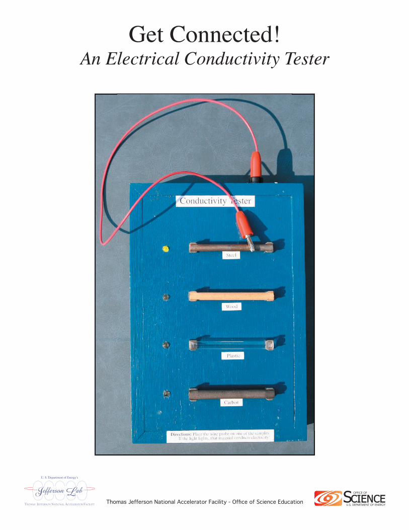
Get Connected!An Electrical Conductivity Tester
An Electrical Conductivity Tester http://education.jlab.org/workbench/
An Electrical Conductivity TesterBackground
Materials can be classifi ed according to their ability to allow electricity to fl ow through them. Materials which do little to impede the fl ow of electricity are classifi ed as conductors while materials which strongly resist the fl ow of electricity are classifi ed as insulators. By attempting to pass a small electrical current through a material, a material's electrical conductance can be tested.
OverviewThe Electrical Conductivity Tester is a simple device that allows students to test different materials to
see whether or not they conduct electricity. The material to be tested is clipped into a pair of quarter inch fuse holders. A probe wire is then used to attempt to pass electricity through the material. If the material conducts electricity, a small light emitting diode (LED) turns on. If the material is non-conductive, the LED remains off.
The main body of the Electrical Conductivity Tester is constructed from sections of 1 × 2 white pine and 1⁄4" plywood. While this set of instructions describes a device which can accommodate four test materials, the design can easily be changed to handle any number of test materials. The Electrical Conductivity Tester is powered by two AAA batteries. A small ballast resistor is used to limit the current provided to the LED.
Component List1 × 2 plank of white pine (roughly 30 inches needed)1⁄4" thick plywood (roughly 1⁄2 square foot needed)1" brads (roughly 12 needed)20 gauge hook-up wire (roughly 1 foot needed)18" long, 22 gauge patch cord, standard banana plug to standard banana plug (1 needed)banana jack, panel mount (1 needed)39 ohm, 1⁄4 Watt resistor (1 needed)green LEDs (T-1 3⁄4 package, 4 needed)1⁄4" diameter printed circuit board fuse clips (8 needed)AAA battery holder, 2 cell capacity (1 needed)AAA batteries (2 needed)4-40 × 3⁄4" machine screws (8 needed)4-40 hex nuts (12 needed)#4 washers (8 needed)adhesive feet (4 needed)5 minute epoxy (1 packet needed)wood glue1⁄4" diameter by 2 3⁄4" long items to test (copper, aluminum, wood, plastic... knock yourself out)

An Electrical Conductivity Tester http://education.jlab.org/workbench/
All of the components have been gathered. All of the wood has been cut and holes for the hardware have been drilled.
An Electrical Conductivity Tester http://education.jlab.org/workbench/
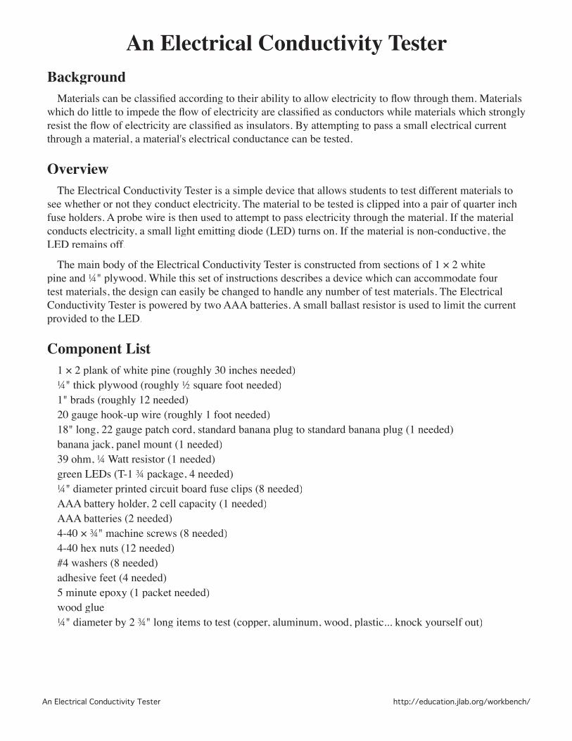
Base Construction 1. Cut two 8 3/4" long pieces from the 1 × 2 white pine board. Miter cut both ends of both pieces to a
45˚ angle. These pieces will form the right and left sides of the base. 2. Cut two 5 7/8" long pieces from the 1 × 2 white pine board. Miter cut both ends of both pieces to a
45˚ angle. These pieces will form the front and back of the base. 3. Use a router to cut a groove 1/4" deep by 7/16" wide on the section of each of the four pieces that
will eventually become the top, inside portion of the base.
The four sides of the base have been cut and a 1/4" deep by 7/16" wide grooves havebeen made in the sections which will become the top, inside portion of the base.
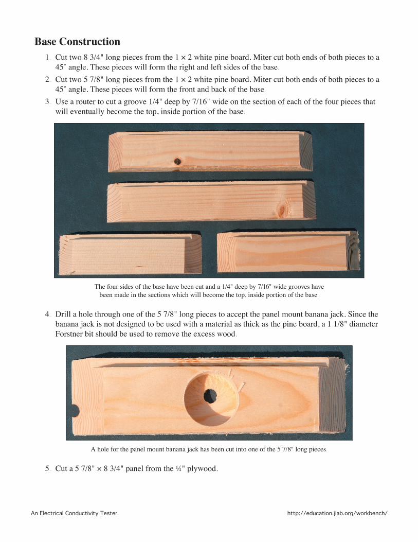
4. Drill a hole through one of the 5 7/8" long pieces to accept the panel mount banana jack. Since the banana jack is not designed to be used with a material as thick as the pine board, a 1 1/8" diameter Forstner bit should be used to remove the excess wood.
A hole for the panel mount banana jack has been cut into one of the 5 7/8" long pieces.
5. Cut a 5 7/8" × 8 3/4" panel from the 1⁄4" plywood.

An Electrical Conductivity Tester http://education.jlab.org/workbench/
6. Use the drill pattern found in Appendix A to drill the appropriate holes in the plywood panel.
Holes for the LEDs and fuse clips have been drilled in the plywood panel.

An Electrical Conductivity Tester http://education.jlab.org/workbench/
7. Join the four sections of the base together. Use wood glue and brads to secure the joints.
The base pieces have been joined together.
8. Use wood glue to attach the plywood panel to the base.
The plywood panel has been glued to the base.

An Electrical Conductivity Tester http://education.jlab.org/workbench/
9. Paint the base, if desired. 10. The base is now complete. It's time to install the hardware!
Assembly 1. Attach the 8 fuse clips to the top of the base using the 4-40 × 3⁄4" machine screws, 4-40 hex nuts and
#4 washers. Align the fuse clips so that the test materials can be clipped between them.
The fuse clips have been attached to the top of the base.
2. Flipping the base over so that you can access its interior, insert the LEDs into their holes. If the leads of the LEDs are long enough, you can save yourself a bit of wiring by rotating the LEDs so that their cathodes are closest to their respective 4-40 × 3⁄4" machine screw. With luck, you will be able to bend the cathodes over and make contact with the 4-40 × 3⁄4" machine screw. You can then secure the cathode to the 4-40 × 3⁄4" machine screw by using another 4-40 hex nut to make a kind of cathode sandwich. If this method is used, make certain the cathode makes contact with the 4-40 × 3⁄4" machine screw at the 6 o'clock position. That way, tightening the upper 4-40 hex nut will tend to draw the cathode in.
Trapping the cathode between a pair of hex nuts can save some soldering!

An Electrical Conductivity Tester http://education.jlab.org/workbench/
3. Insert the panel mount banana jack into the hole that was created in one of the 5 7/8" long pieces. The jack portion of the piece should be on the base's outer surface and the electrical hook-up portion should be in the base's interior.
4. Use the Point to Point Wiring Guide, found in Appendix B, or the Circuit Diagram, found in Appendix C, to complete the wiring. Again, if the leads of the LEDs are long enough, you may be able to bend the anodes of neighboring LEDs together and solder them together directly.
5. Once the wiring is complete, secure the battery pack and the LEDs to the base with dabs of epoxy.
All wiring is complete and the LEDs and battery pack are secured to the base with epoxy.
6. Insert two AAA batteries into the battery holder. 7. Attach four adhesive feet to the bottom of the base and fl ip the contraption over. It's now more or
less ready to go!
OperationSnap the items you wish to test into the fuse holders and plug one end of the 18" long patch cord
into the panel mount banana jack. Touching the free end of the patch cord to one of the test items will determine whether or not that item conducts electricity. If the material is a conductor, the circuit is completed and the corresponding LED lights up. Otherwise, the circuit remains open and the corresponding LED stays off.

An Electrical Conductivity Tester http://education.jlab.org/workbench/
Appendix A - Top Plate Drill Pattern
3/16" 1/8" 1/8"
1.000"
2.5"
0.971"
1.6"

An Electrical Conductivity Tester http://education.jlab.org/workbench/
Appendix B - Point to Point Wiring GuideThis diagram shows the components as seen from inside the base. Resistors are represented by rounded
rectangles. The fl at end of the LED is the cathode. Small, dark circles indicate a soldered connection.
Banana Jack
39
Battery PackNegative (black)
Positive (red)
Green LED
Green LED
Green LED4-40 Screw
Green LED
Green LED
4-40 Screw
4-40 Screw
4-40 Screw

An Electrical Conductivity Tester http://education.jlab.org/workbench/
Appendix C - Circuit Diagram
39�