Embed Size (px)
Citation preview

VITA 20-199x Draft Standard
Do not specify or claim conformance to this draft standard Conduction Cooled PMC, VITA 20-199x/D1.1011 1
Conduction Cooled PCI Mezzanine Card (CCPMC) Draft Standard
VITA 20 - 199x
Draft 1.1011
OctoberNovember, 1999
This draft standard is being prepared by the VITA Standards Organization (VSO) and is unapproved.
Do not specify or claim conformance to this draft standard.
VSO is the Public Domain Administrator of this draft standard and guards the contents from change
except by sanctioned meetings of the task group under due process.
VITA Standards Organization 7825 East Gelding Drive, Suite 104
Scottsdale, AZ 85260 Ph: 602-951-8866 Fx: 602-951-0720
Hp: http://www.vita.com/

VITA 20-199x Draft Standard
Do not specify or claim conformance to this draft standard 2 Conduction Cooled PMC, VITA 20-199x/D1.1011
Table of Contents
1 Introduction.................................................................................................................7
1.1 Terminology, Definitions and Abbreviations...............................................................87 1.2 References.............................................................................................................109 1.3 Standard Terminology............................................................................................109
2 CCPMC Specification...........................................................................................1211
2.1 Requirements.......................................................................................................1211 2.2 Compatibility........................................................................................................1312 2.3 Theory of Operation and Usage............................................................................1413
2.3.1 Component Layout ......................................................................................1413
3 Conduction Cooled PMC Mechanics ...................................................................1514
4 Conduction Cooled Host Card Mechanics...........................................................1716
5 Thermal Interface Mechanics ..............................................................................1918
List of Figures
FIGURE 2-1 DIAGRAM OF SINGLE CCPMC FITTED ONTO A HOST CARD.......1211 FIGURE 3-1 CCPMC MEZZANINE MODULE ...........................................................1615 FIGURE 4-1 CCPMC HOST MODULE........................................................................1817 FIGURE 5-1 THERMAL INTERFACE DEFINITIONS ................................................2120
List of Tables
TABLE 2-1 COMPATIBILITY MATRIX......................................................................1312
VITA 20-199x Draft Standard
Do not specify or claim conformance to this draft standard Conduction Cooled PMC, VITA 20-199x/D1.1011 3
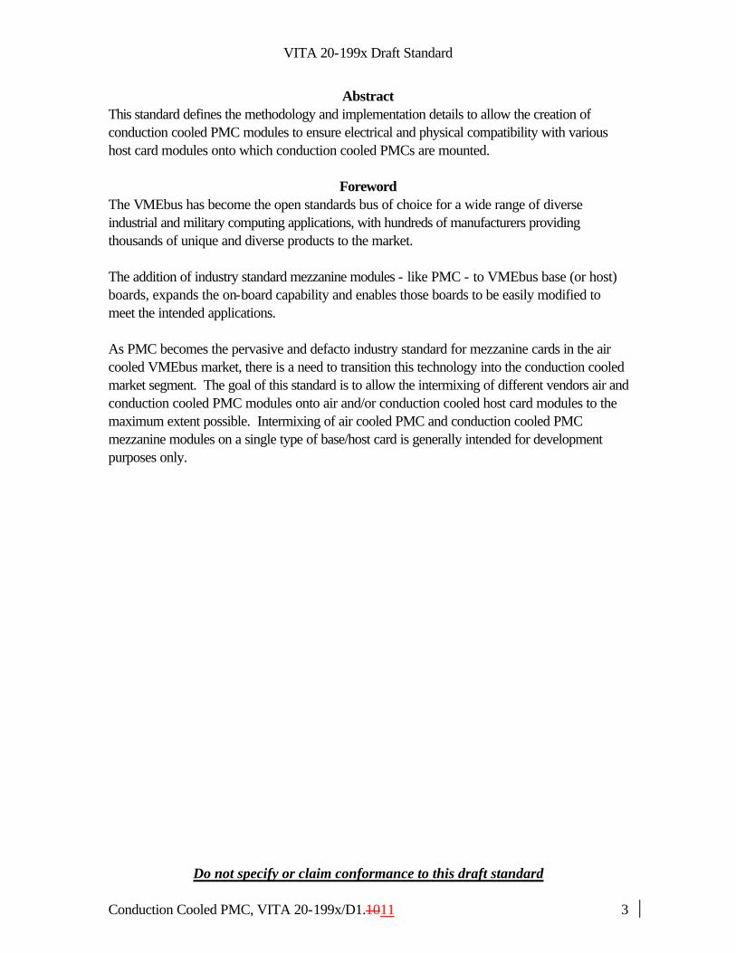
Abstract This standard defines the methodology and implementation details to allow the creation of conduction cooled PMC modules to ensure electrical and physical compatibility with various host card modules onto which conduction cooled PMCs are mounted.
Foreword The VMEbus has become the open standards bus of choice for a wide range of diverse industrial and military computing applications, with hundreds of manufacturers providing thousands of unique and diverse products to the market. The addition of industry standard mezzanine modules - like PMC - to VMEbus base (or host) boards, expands the on-board capability and enables those boards to be easily modified to meet the intended applications. As PMC becomes the pervasive and defacto industry standard for mezzanine cards in the air cooled VMEbus market, there is a need to transition this technology into the conduction cooled market segment. The goal of this standard is to allow the intermixing of different vendors air and conduction cooled PMC modules onto air and/or conduction cooled host card modules to the maximum extent possible. Intermixing of air cooled PMC and conduction cooled PMC mezzanine modules on a single type of base/host card is generally intended for development purposes only.
VITA 20-199x Draft Standard
Do not specify or claim conformance to this draft standard 4 Conduction Cooled PMC, VITA 20-199x/D1.1011
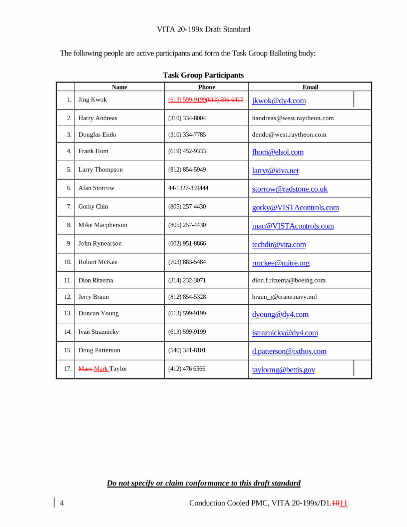
The following people are active participants and form the Task Group Balloting body:
Task Group Participants Name Phone Email
1. Jing Kwok (613) 599-9199(613) 596-6417 [email protected]
2. Harry Andreas (310) 334-8004 [email protected]
3. Douglas Endo (310) 334-7785 [email protected]
4. Frank Hom (619) 452-9333 [email protected]
5. Larry Thompson (812) 854-5949 [email protected]
6. Alan Storrow 44-1327-359444 [email protected]
7. Gorky Chin (805) 257-4430 [email protected]
8. Mike Macpherson (805) 257-4430 [email protected]
9. John Rynearson (602) 951-8866 [email protected]
10. Robert McKee (703) 883-5484 [email protected]
11. Dion Ritzema (314) 232-3071 [email protected]
12. Jerry Braun (812) 854-5328 [email protected]
13. Duncan Young (613) 599-9199 [email protected]
14. Ivan Straznicky (613) 599-9199 [email protected]
15. Doug Patterson (540) 341-8101 [email protected]
17. Marc Mark Taylor (412) 476 6566 [email protected]

VITA 20-199x Draft Standard
Do not specify or claim conformance to this draft standard Conduction Cooled PMC, VITA 20-199x/D1.1011 5
-- The following 7 sections will not be included in the final standard --
Comments, Corrections and/or Additions
Anyone wishing to provide comments, corrections and/or additions to this proposed draft standard, please direct them to the Task Group chair:
Mike Macpherson VITA 20 Chair & Draft Editor VISTA Controls
27825 Fremont Court Santa Clarita, CA 91355
Phone: 661-257-4430 Fax: 661-257-4782 Email: [email protected] Web site: http://www.VISTAcontrols.com
The best method to provide corrections and small additions is via marking up the specific pages and faxing them to the chair. For longer additions, please provide textual information via email. This draft standard has been prepared and is being edited in Microsoft Word 2000, under Windows 98.
VSO and Other Standards
Should anyone want information on other standards being developed by VSO, VME Product Directories, VME Handbooks, or general information on the VME market, please contact the VITA office at the address or phone number given on the front cover. Copies of the VSO minutes plus VSO meeting announcements and agenda can be retrieved from VITA Home Page listed on the front cover. Copies of various draft standards can also be downloaded from VITA Home Page.
Change Bars
All paragraphs changed in this draft from draft 1.9 are marked with a change bar on the right side of the paragraph. Any table entry that was changed will have a double bar on the right side of changed entry.
Draft Summary
Draft 1.10 represents minor changes to draft 1.9. Specifically, figure 4-1 was accidentally deleted and the footers did not reflect the correct draft revision. Additionally, the Task Group Chair and draft editor has changed from Hans Ohman of DY4 to Mike Macpherson of VISTA Controls.
VITA 20-199x Draft Standard
Do not specify or claim conformance to this draft standard 6 Conduction Cooled PMC, VITA 20-199x/D1.1011
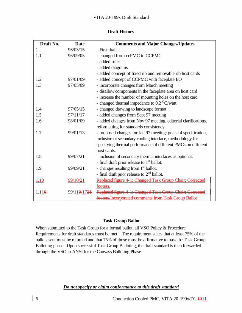
Draft History
Draft No. Date Comments and Major Changes/Updates 1 96/03/15 - First draft 1.1 96/09/05 - changed from ccPMC to CCPMC
- added rules - added diagrams - added concept of fixed rib and removable rib host cards
1.2 97/01/09 - added concept of CCPMC with faceplate I/O 1.3 97/05/09 - incorporate changes from March meeting
- disallow components in the faceplate area on host card - increase the number of mounting holes on the host card - changed thermal impedance to 0.2 OC/watt
1.4 97/05/15 - changed drawing to landscape format 1.5 97/11/17 - added changes from Sept 97 meeting 1.6
98/01/09 - added changes from Nov 97 meeting, editorial clarifications, reformatting for standards consistency
1.7 1.8 1.9
99/01/13 99/07/21 99/09/21
- proposed changes for Jan 97 meeting: goals of specification, inclusion of secondary cooling interface, methodology for specifying thermal performance of different PMCs on different host cards. - inclusion of secondary thermal interfaces as optional. - final draft prior release to 1st ballot. - changes resulting from 1st ballot. - final draft prior release to 2nd ballot.
1.10 99/10/21 Replaced figure 4-1; Changed Task Group Chair; Corrected footers.
1.110 99/110/1721 Replaced figure 4-1; Changed Task Group Chair; Corrected footers.Incorporated comments from Task Group Ballot
Task Group Ballot
When submitted to the Task Group for a formal ballot, all VSO Policy & Procedure Requirements for draft standards must be met. The requirement states that at least 75% of the ballots sent must be returned and that 75% of those must be affirmative to pass the Task Group Balloting phase. Upon successful Task Group Balloting, the draft standard is then forwarded through the VSO to ANSI for the Canvass Balloting Phase.
VITA 20-199x Draft Standard
Do not specify or claim conformance to this draft standard Conduction Cooled PMC, VITA 20-199x/D1.1011 7
1 Introduction This standard defines the mechanical and thermal interface for a conduction cooled PCI mezzanine card (CCPMC) to allow compatible intermatability of products. This standard is based on the physical (mechanical) layers defined in IEEE P1386/P1386.1 (CMC/PMC) draft standard, however provision has been made for increased mechanical support for enhanced shock and vibration performance. Typical usage would be for a CCPMC module to be fitted on top of a host VMEbus card that conforms to IEEE 1101.2-1992, Standard for Mechanical Core Specifications for Conduction-Cooled Eurocards. However, it is possible for a CCPMC card to be fitted to any other host card as long as that host card presents a mechanical and thermal interface that conforms to this specification. The thermal interfaces to the host has been achieved with minimum restriction to the mezzanine component area by utilizing the front panel and central stiffening bar areas, normally associated with a conduction cooled assembly. Additional thermal interfaces are optional for enhanced thermal performance, however these thermal interfaces further reduce available component area. The CMC/PMC standard defines a printed circuit board (PCB) profile that extends beyond the component boundary of the VME base card. Therefore, the PCB length must be reduced from 149.0 mm to 143.75 mmthe PCB length must be reduced to be compliant with IEEE 1101.2. The reduction in length does not impact the bezel holes and therefore compatibility with air-cooled assemblies is maintained. Similarly, the base card zero-component-height and mezzanine card component I/O boundary areas are maintained so that the mezzanine card artwork can accommodate front panel I/O as well as increased component heights. The front panel I/O connectors would not normally be fitted on conduction cooled assemblies, the I/O being mapped to the motherboard J2 or P0 via the Pn4 mezzanine card connector. The position of the CCPMC front edge and connectors Pn1 to Pn4 are unchanged with respect to the front edge of the base card.
VITA 20-199x Draft Standard
Do not specify or claim conformance to this draft standard 8 Conduction Cooled PMC, VITA 20-199x/D1.1011
1.1 Terminology, Definitions and Abbreviations
The following terminology, definitions and abbreviations are utilized throughout this document and are stated here for clarification. Air cooled
A methodology of cooling active and passive components on a CCA by utilizing either natural free, or forced air convection from an area of higher temperature to lower temperature.
CCA Abbreviation for Circuit Card Assembly
CCPMC Abbreviation for Conduction Cooled PCI Mezzanine Card
Conduction cooled A methodology of cooling active and passive components on a CCA by utilizing direct heat conduction from an area of higher temperature to lower temperature.
Host Card A module that inserts into a mother board (or backplane) which holds a mezzanine card.
Mezzanine Card An add-on printed circuit board (PCB) which is mounted parallel to a host (or base) computer board module.
PCI Peripheral Component Interconnect
VITA 20-199x Draft Standard
Do not specify or claim conformance to this draft standard Conduction Cooled PMC, VITA 20-199x/D1.1011 9
PMC Abbreviation for PCI Mezzanine Card
CMC Abbreviation for Common Mezzanine Card
Thermal Interface Physical area specifically allocated for direct mechanical contact for the conduction of heat from a lower level assembly to a higher level assembly.
VITA 20-199x Draft Standard
Do not specify or claim conformance to this draft standard 10 Conduction Cooled PMC, VITA 20-199x/D1.1011
1.2 References
IEEE 1101.2-1992 Mechanical Core Specifications for Conduction Cooled Eurocard ANSI/VITA 1-1994 VMEbus standard ANSI/VITA 1.1 – 1997 VME64 Extensions Standard IEEE P1386/Draft 2.0 CMC Draft Standard IEEE P1386.1/Draft 2.0 PMC Draft Standard IEEE 1101.1 -1991 Eurocard specification ISO 4527 Autocatalytic Nickel Phosphorus Coatings - Specification and Test
Methods ISO 7599
Anodizing of Aluminum and Its Alloys – General Specification for Anodic Oxide Coating on Aluminum
1.3 Standard Terminology
To avoid confusion and to make very clear what the requirements for compliance are, many of the paragraphs in this standard are labeled with keywords that indicate the type of information they contain. The keywords are listed below: Rule Recommendation Suggestion Permission Observation Any text not labeled with one of these keywords describes the structure or operation. It is written in either a descriptive or a narrative style. These keywords are used as follows: Rule <chapter>.<number>: Rules form the basic framework of this draft standard. They are sometimes expressed in the text form and sometimes in the form of figures, tables or drawings. All rules shall be followed to ensure compatibility between board and backplane designs. All rules use the words “shall” or “shall not” to emphasize the importance of the rule. The words “shall” or “shall not” are reserved exclusively for stating rules in this draft standard and are not used for any other purpose.
VITA 20-199x Draft Standard
Do not specify or claim conformance to this draft standard Conduction Cooled PMC, VITA 20-199x/D1.1011 11
Recommendation <chapter>.<number>: Wherever a recommendation appears, designers would be wise to take the advice given. Doing otherwise might result in some awkward problems or poor performance or some levels of incompatibility. While the architecture has been designed to support high-performance systems, it is possible to design a system that complies with all the rules but has abysmal performance. In many cases a designer needs a certain level of experience in order to design boards that deliver top performance. Recommendations found in this standard are based on this kind of experience and are provided to designers to speed their traversal of the learning curve. All recommendations use the words “should” or “should not” to emphasize the importance of the recommendation. The words “should” or “should not” are reserved exclusively for stating permission in this draft standard and are not used for any other purpose. Suggestion <chapter>.<number>: A suggestion contains advice which is helpful but not vital. The reader is encouraged to consider the advice before discarding it. Some design decisions that need to be made in the designing boards are difficult until experience has been gained. Suggestions are included to help a designer who has not yet gained this experience. Some suggestions have to do with designing boards that can be easily reconfigured for compatibility with other boards, or with designing the board to make the job of the system integration and debugging easier. Permission <chapter>.<number>: In some cases, a rule does not specifically prohibit a certain design approach, but the reader might be left wondering whether that approach night violate the spirit of the rule or whether it might lead to some subtle problem. Permissions reassure the reader that a certain approach is acceptable and will cause no problems. All permissions use the words “may” or “may not” to emphasize the importance of the permission. The lower-case “may” words are reserved exclusively for stating permissions in this draft standard and are not used for any other purpose. Observation <chapter>.<number>: Observations do not offer any specific advise. They usually follow naturally from what information has just been presented. They spell out the implications of certain rules and bring attention to things that might otherwise be overlooked. They also give the rationale behind certain rules so that the reader understands why the rule must be followed.

VITA 20-199x Draft Standard
Do not specify or claim conformance to this draft standard 12 Conduction Cooled PMC, VITA 20-199x/D1.1011
2 CCPMC Specification
2.1 Requirements
Mezzanine cards are generally utilized to maximize the available board surface area of a CCA mounted into a physical backplane/chassis slot. Typical applications of these would include conduction and air-cooled card cages and chassis. Figure 2-1 illustrates a single size PMC mezzanine card mounting onto a host card as defined by this standard. Host VMEbus cards can typically accommodate 1 or 2 PMC modules. Mounting and pin-outs are defined in the related CMC and PMC standards.
P0P2
CCPMC Mezzanine
Host CardCenter Rib
P1
Face Plate Rib
PMC Connectors
Figure 2-1 Diagram of single CCPMC fitted onto a host card
There can be eight (8) types of PMCs applicable to this standard:
1. Air cooled PMCs with faceplate I/O 2. Air cooled PMCs backplane I/O 3. Air cooled PMCs with both type of I/O 4. Air cooled PMCs without any I/O (e.g. memory expansion card) 5. Conduction cooled PMCs with faceplate I/O 6. Conduction cooled PMCs without faceplate I/O 7. Conduction cooled PMCs with both types of I/O 8. Conduction cooled PMCs without any I/O

VITA 20-199x Draft Standard
Do not specify or claim conformance to this draft standard Conduction Cooled PMC, VITA 20-199x/D1.1011 13
There are also three types of host cards: 1. Air cooled host cards
2. Conduction cooled host cards with fixed ribs 3. Conduction cooled host cards with removable ribs
2.2 Compatibility
The following table describes the compatibility between mezzanine cards and the host card. “Fully compatible” means that the mezzanine card can be fitted on top of that host card without interference. The goal is that all conduction cooled mezzanine cards can be fitted on both air cooled and conduction cooled host cards and air cooled mezzanine cards can be fitted on conduction cooled host cards with removable ribs for use in a development environment.
Table 2-1 Compatibility Matrix
Air cooled
mezzanine cards with faceplate
I/O
Air cooled mezzanine cards without faceplate
I/O
Conduction cooled mezzanine cards without faceplate
I/O
Conduction cooled mezzanine cards with faceplate I/O
Air cooled host card
fully compatible fully compatible fully compatible fully compatible
Conduction cooled host card (fixed rib)
not compatible not compatible (note 1)
fully compatible (note 4)
not compatible (note 4)
Conduction cooled host card (removable rib)
lab compatible (note 2)
lab compatible (note 2)
fully compatible (note 4)
fully compatible (note 3)
Notes: 1. Air cooled mezzanine cards without faceplate I/O could be compatible with conduction
cooled host cards with fixed ribs if components on the mezzanine do not interfere with the stiffening ribs on the host card.
2. Although air cooled mezzanine cards can be fitted on conduction cooled host cards with removable ribs, these mezzanine cards may not have been designed to operate in a deployable environment. It is envisioned that this combination would be used in a laboratory/prototyping environment only.
3. Conduction cooled mezzanine cards with faceplate I/O will require a modification to the faceplate rib. This will to some degree affect thermal and structural performance.
4. Conduction cooled host card may have to be configured to accept a specific conduction cooled mezzanine card, depending on use of optional thermal interfaces.

VITA 20-199x Draft Standard
Do not specify or claim conformance to this draft standard 14 Conduction Cooled PMC, VITA 20-199x/D1.1011
2.3 Theory of Operation and Usage
Conduction-cooled modules are used wherever convection cooling or forced air cooling is not possible or appropriate for the end-use application. For example, a CCA might consist of a PWB bonded to a conduction plate. The conduction plate is a metallic panel that conducts heat from CCA components to the edge of the CCA. The conduction plate is a three-dimensional part requiring small tolerances to ensure that it does not interfere with component leads and that it provides accurate location of the CCA in the chassis card slot. Conduction cooling can also be accomplished by embedding metal layers and thermal vias within the core of the PWB and/or incorporating optional metal inserts to match various component heights.
2.3.1 Component Layout
Conduction-cooled CCAs used in rugged and extended temperature environments present certain design challenges. Of prime concern is the layout of components to ensure efficient and effective heat transfer to card edge. A number of principles can be stated that help define the component layout on a conduction-cooled CCA. In general, the heat flow is from the center line of the CCA to the thermal interface (or sink) normally located at the top and bottom edges. Components with a significant dissipation should be placed such that the thermal path to the CCA edge is minimized. To ensure a robust mechanical performance, typical implementations of CCAs using this specification would incorporate stiffening ribs that run along the height axis. Depending on the end application, one, two, or three stiffening ribs could be positioned between the connector and the front edge. The best mechanical support is along the edges of the CCA with good support along the stiffening ribs. High-dissipation parts would have priority at the card edge. This specification allows for conduction cooled CCAs to have stiffening ribs that can be either fixed or removable.
VITA 20-199x Draft Standard
Do not specify or claim conformance to this draft standard Conduction Cooled PMC, VITA 20-199x/D1.1011 15
3 Conduction Cooled PMC Mechanics Rule 3.1 CCPMCs shall be designed to fit on all air cooled PMC fitted host
cards per Table 2-1. See Figure 3-1 CCPMC Mezzanine Module.
Rule 3.2 Components on a CCPMC shall conform to the envelope specifications as defined in IEEE P1386 Common Mezzanine Card Specification Figure 4-8. The minimum stacking height of a CCPMC connector shall be 10 mm. 8 and 9 mm stacking heights are disallowed.
Permission 3.1 A CCPMC may be single width or double width.
Permission 3.2 A CCPMC may use fewer screw fastening locations than defined in Figure 3-1 as long as specified thermal and vibration specifications are met.
Permission 3.3 Observation 3.1
CCPMC may not have front panel bracket fitted. However standard mounting holes are provided. Optimal mechanical and thermal performance is obtained when all screw fastening locations are utilized.
Rule 3.3 CCPMC shall provide all features as per Figure 3-1. Rule 3.4 Electrical ground returns shall not be made through the thermal interface.
VITA 20-199x Draft Standard
Do not specify or claim conformance to this draft standard 16 Conduction Cooled PMC, VITA 20-199x/D1.1011
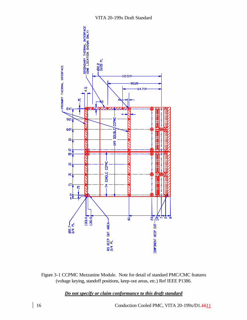
Figure 3-1 CCPMC Mezzanine Module. Note for detail of standard PMC/CMC features (voltage keying, standoff positions, keep-out areas, etc.) Ref IEEE P1386.
VITA 20-199x Draft Standard
Do not specify or claim conformance to this draft standard Conduction Cooled PMC, VITA 20-199x/D1.1011 17
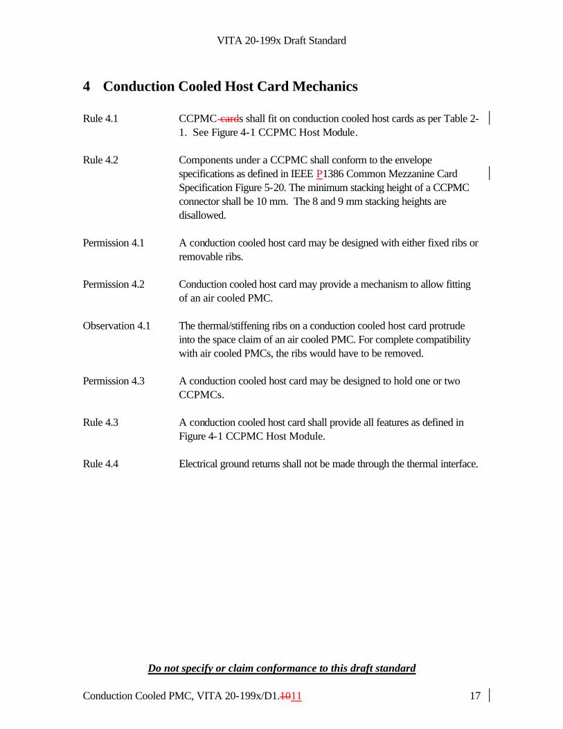
4 Conduction Cooled Host Card Mechanics
Rule 4.1 CCPMC cards shall fit on conduction cooled host cards as per Table 2-1. See Figure 4-1 CCPMC Host Module.
Rule 4.2 Components under a CCPMC shall conform to the envelope specifications as defined in IEEE P1386 Common Mezzanine Card Specification Figure 5-20. The minimum stacking height of a CCPMC connector shall be 10 mm. The 8 and 9 mm stacking heights are disallowed.
Permission 4.1 A conduction cooled host card may be designed with either fixed ribs or removable ribs.
Permission 4.2 Conduction cooled host card may provide a mechanism to allow fitting of an air cooled PMC.
Observation 4.1 The thermal/stiffening ribs on a conduction cooled host card protrude into the space claim of an air cooled PMC. For complete compatibility with air cooled PMCs, the ribs would have to be removed.
Permission 4.3 A conduction cooled host card may be designed to hold one or two CCPMCs.
Rule 4.3 A conduction cooled host card shall provide all features as defined in Figure 4-1 CCPMC Host Module.
Rule 4.4 Electrical ground returns shall not be made through the thermal interface.

VITA 20-199x Draft Standard
Do not specify or claim conformance to this draft standard 18 Conduction Cooled PMC, VITA 20-199x/D1.1011
Figure 4-1 CCPMC Host Module Note for detail of standard PMC/CMC features (voltage keying, standoff positions, keep-out areas, etc.) Ref IEEE P1386
VITA 20-199x Draft Standard
Do not specify or claim conformance to this draft standard Conduction Cooled PMC, VITA 20-199x/D1.1011 19
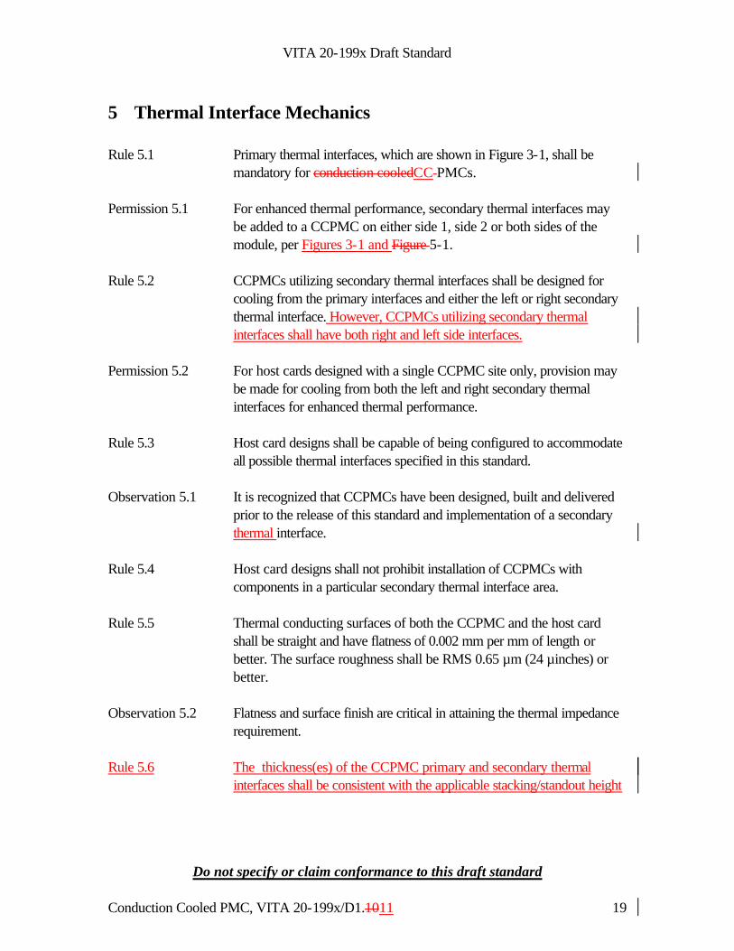
5 Thermal Interface Mechanics Rule 5.1 Primary thermal interfaces, which are shown in Figure 3-1, shall be
mandatory for conduction cooledCC PMCs. Permission 5.1 For enhanced thermal performance, secondary thermal interfaces may
be added to a CCPMC on either side 1, side 2 or both sides of the module, per Figures 3-1 and Figure 5-1.
Rule 5.2 CCPMCs utilizing secondary thermal interfaces shall be designed for cooling from the primary interfaces and either the left or right secondary thermal interface. However, CCPMCs utilizing secondary thermal interfaces shall have both right and left side interfaces.
Permission 5.2 For host cards designed with a single CCPMC site only, provision may be made for cooling from both the left and right secondary thermal interfaces for enhanced thermal performance.
Rule 5.3 Host card designs shall be capable of being configured to accommodate all possible thermal interfaces specified in this standard.
Observation 5.1 It is recognized that CCPMCs have been designed, built and delivered prior to the release of this standard and implementation of a secondary thermal interface.
Rule 5.4 Host card designs shall not prohibit installation of CCPMCs with components in a particular secondary thermal interface area.
Rule 5.5 Thermal conducting surfaces of both the CCPMC and the host card shall be straight and have flatness of 0.002 mm per mm of length or better. The surface roughness shall be RMS 0.65 µm (24 µinches) or better.
Observation 5.2 Flatness and surface finish are critical in attaining the thermal impedance requirement.
Rule 5.6 The thickness(es) of the CCPMC primary and secondary thermal interfaces shall be consistent with the applicable stacking/standout height
VITA 20-199x Draft Standard
Do not specify or claim conformance to this draft standard 20 Conduction Cooled PMC, VITA 20-199x/D1.1011
Rule 5.6 The thermal conducting surfaces of both the CCPMC and the host card
shall be corrosion resistant or treated to resist corrosion.
Observation 5.3 Corrosion products on conduction clamping surfaces have been shown to substantially degrade thermal performance over time.
Permission 5.3 Aluminum structure may be sulfuric anodized and sealed to meet this rule, ref: ISO 7599.
Observation 5.4 Hard anodizing is not recommended as the hard oxide case substantially inhibits heat transfer.
Permission 5.4 Aluminum structure may be electrolyses nickel plated to meet this rule, ref: ISO 4527.

VITA 20-199x Draft Standard
Do not specify or claim conformance to this draft standard Conduction Cooled PMC, VITA 20-199x/D1.1011 21
Secondary ThermalInterface Regions(on both Side 1 &Side 2)
Side 2
Side 1
Right Side
Left Side
Primary ThermalInterface Regions(on Side 1 only)
Figure 5-1 Thermal Interface Definitions