Embed Size (px)
Citation preview

APPLICATION NOTE
CONDITION MONITORING APPLICATION OF ULTRASOUND TECHNOLOGY
CHRISTIAN PROBST, PETER HOLSTEIN

2
CONDITION MONITORING - APPLICATION OF ULTRASOUND TECHNOLOGY
www.sonotec.eu
CONTENTSForeword 3
Introduction 4
Condition monitoring as a tool of condition-based maintenance 5
Ultrasound in the field of maintenance 6
The new hand-held ultrasound detector SONAPHONE 7
New broadband ultrasound sensors for condition monitoring 9
Application examples 11Wafer dicing saw 11
Ball bearing defect detection 15
Conclusions 16
SONOTEC GmbHNauendorfer Str. 206112 Halle (Saale)Deutschland+49 (0)345 / 133 17-0+49 (0)345 / 133 [email protected]
SONOTEC preserves the right to change technical specifications without further notice. (Rev. 1 / 2019-05-10)

3
CONDITION MONITORING - APPLICATION OF ULTRASOUND TECHNOLOGY
www.sonotec.eu
Foreword
Christian ProbstSensor DeveloperSONOTEC Ultraschallsensorik Halle GmbH
Christian Probst
The most important applications of vibra-tion-based measurement technologies are related to the monitoring of rotating and reciprocating machinery. Vibration analysis and technical acoustic investigations are predominantly carried out in the frequency range up to 20 kHz. However, many technical and physical processes generate sound and vibration at higher frequencies. Most current ultrasound testing instruments enable users to access relatively simple parameters, such as sound level, recorded and converted by narrowband sensors and electronics. This
limits the informative value of ultrasound measuring results, since most physical processes generate ultrasound in a broad frequency range. Therefore, an approach has been developed for broadband monitoring of processes up to frequencies of about 200 kHz.Vibration and ultrasound can be conside-red closely related to one other. Ultrasound provides early indications of bearing distress and material wear, which are useful for analy-sing the trend of machinery state. Vibration and ultrasound can be used in combination with one another. An important prerequisite for the exploitation of the complete physical-ly-based information in acoustical broadband signals is the use of proper sensors. There-fore sensors have been developed on the basis of new piezoelectric composite mate-rials. The physical and construction principles enable acoustic measurements in a wide frequency range. The frequency characte-ristic of the sensors can be linearised to a certain extent. This will be demonstrated by means of some significant applications, such as friction, process monitoring of a wafer di-cing machine and the diagnostics of bearing damage. The novel sensors are part of a new modular and scalable measurement concept that includes data acquisition and treatment, the use of algorithms in real time and impro-ved calculations and predictions.

4
CONDITION MONITORING - APPLICATION OF ULTRASOUND TECHNOLOGY
www.sonotec.eu
The increasing importance of maintenance is due to the ever-growing automation of technical processes. With the increasing le-vel of automation and complexity of machi-nes and facilities, the technical and organi-sational conjunction of plants, and thereby the cost of failures, will be enlarged. This leads to increased requirements in terms of the availability and productivity of machines and facilities. Additionally, the requirements concerning safety at work and environmen-tal protection will be increased in the same way.
Various strategies for maintenance have been developed over recent years in order to meet these requirements. At the begin-ning of maintenance evolution, a repair was only carried out after damage had occurred and downtimes were often non-critical. The machines were of a simple design and/or oversized. During the second generation of maintenance, from about 1960 to 1980, time-scheduled maintenance was establi-shed to meet the increasing requirements in productivity. During the third genera-tion of maintenance (since the 1980s) the availability and the reliability of machines and facilities have been the most important factors of production. Economic pressure constraints demand the optimisation of not only the costs associated with production but also the costs associated with mainte-nance. This has resulted in the introduction of condition-based maintenance (CBM). With CBM, a repair is only carried out if it is really necessary, depending on the actual condition of the process or machine1,2.
1 https://www.ba-leipzig.de/fileadmin/upload_ba/allgemein/Antrittsvorle-
sung_Morning_110629.pdf, 27.04.2015.
2 J Moubray, Reliability-Centered Maintenance, Second Edition, Butter-
worth Heinemann, 1997. ISBN 0-7506-3358-1
Chapter 1
Introduction
Fig. 1: Digital Ultrasonic Testing Device SONAPHONE
5
CONDITION MONITORING - APPLICATION OF ULTRASOUND TECHNOLOGY
www.sonotec.eu
Chapter 2
Condition monitoring as a tool of condition-based maintenance
The objective of condition-based mainte-nance or predictive maintenance (PdM) is to initiate a timely maintenance measure. ‘Timely’ means early enough to keep the repair expenditure as small as possible before greater damage occurs that requires increased effort, yet as late as possible to minimise the downtime of a machine and to maximise the usage of parts up to the end of their lifecycle. It is a major challenge to ensu-re the latest moment of safe use. As a result of this, the first strategy is often used in practice. The aim of condition-based strategy is therefore to minimise maintenance costs through early fault detection and repair3. The early identification of defect indications is the essential mission of ultrasound-based diagnostic methods.Condition monitoring is generally defined as the usage of appropriate technologies to ascertain the actual operating state of a machine. The operational state is the super-position of process and machine condition. In the past, the operator or service techni-cian had to carry out condition monitoring using only senses, such as hearing, seeing or feeling. Today, because many machines and processes are running unmanned and facilities are becoming more and more com-plex, a monitoring technique is needed. In
addition, such a technique could offer many new possibilities to monitor parameters 24 hours a day, without interruption. This means that unmanned machines and systems can be remotely controlled with relative ease. Various parameters, such as temperature, pressure, flow, oil quality or vibration, can be monitored in order to detect the operating state of a machine3. Said parameters can be supplemented by further parameters, such as the drive spindle current or force. The last two parameters mentioned are often made available to the operator of machine tools on the machine ex-factory. As most of the errors on machines with rotating parts lead to vibrations, most information about the state of a machine (the machine’s health) as well as the process parameters (the opera-ting characteristics) can be captured through condition monitoring by means of vibration measurement3. This means that it is possi-ble to monitor both the machine’s state and the process state with just one technology. This capability to optimise productivity and maintenance simultaneously can significan-tly improve the overall efficiency of plants.
3 C Ugechi, E Ogbonnaya, M Lilly, S Ogaji and S Probert, ‘Condition-based dia-
gnostic approach for predicting the maintenance requirements of machinery’,
Engineering, Vol 1, No 3, pp 177-187, 2009. DOI: 10.4236/eng.2009.13021

6
CONDITION MONITORING - APPLICATION OF ULTRASOUND TECHNOLOGY
www.sonotec.eu
Chapter 3
Ultrasound in the field of maintenance
Due to the previously described advantages, vibration measurement is, in practice, the first choice of means for monitoring machi-nes with rotating parts. Vibration sensors with a linear frequency response of up to 20 kHz are typically used for measuring vibra-tions. Since the acoustic processes that can be used for maintenance cover a further fre-quency range of up to 1 MHz, special sen-sors are necessary. These ultrasonic sensors are used if the frequencies to be tested are too high, but also if the deflections are too small, for vibration sensors4. Furthermore, the analysis in the ultrasound range offers the advantage that the multitude of machine noise in the audible range does not interfere with the measure-ment.The use of ultra-sound methods is classified by the authors as a complementa-ry approach to vibration analysis. The causes for the generation of
sound emissions in the ultrasound range differ from those for the generation of vibra-tions. The most important impacts that must be recorded in maintenance are ultimate-ly based on friction. Such operations are, for example, lubrication monitoring or dry running detection, leakage flows and tech-nical friction processes on plain bearings or brakes. However, other causes of sound emission, such as turbulence, cavitation or discharge processes, also extend the
Fig. 2: Overview of maintenance applications with ultrasound
4 R X Perez and A P Conkey, Is My Machine OK? A Field Guide to Asses-
sing Process Machinery, Industrial Press, 2012. ISBN 978-083113440-2

7
CONDITION MONITORING - APPLICATION OF ULTRASOUND TECHNOLOGY
www.sonotec.eu
scope to processes that do not originate in machines with rotating parts. For all of these causes, the advantages of ultraso-und methods are used to detect damage or process change as early as possible. As shown in Figure 2, the type of signal detection and thus the use of ultrasound in maintenance can be divided into the two categories of airborne sound and structure--borne sound. In the case of airborne sound, applications such as leak detection on compressed air systems, active leak testing on cabins
and containers or the detection of partial discharges are already known. Structure-borne sound applications such as steam trap testing, bearing diagnostics and valve testing are already established. Ultrasonic sensors based on piezoelectric composite materials have been developed and used for structure-borne sound applications for process monitoring. With flat frequency response and high sensitivity, these new sensors are suitable for broadband applica-tions.
Chapter 4
The new hand-held ultrasound detector SONAPHONE
In 2016, SONOTEC Ultraschallsensorik Halle GmbH launched a new testing devi-ce. The device is designed for ultrasonic inspection tasks in the field of maintenan-ce. The main differences between this and previously available devices are the wide frequency range of the sensors and the modular concept of the digital measuring device. In addition, all of the functionali-ties of established mobile devices such as smartphones and tablets are integrated in the novel hand-held ultrasound detector. With the new SONAPHONE, a frequency range of 20-100 kHz can be detected and evaluated. The device will be provided with
application-specific apps, which will assist the maintenance engineer during testing, as well as during data evaluation and test documentation.The SONAPHONE has been developed as a mobile hand-held testing device for all of the aforementioned maintenance applications. At the moment, the platform is designed for the synchronous recording and processing of two signals: ultrasound and temperature signal (implemented in the structure-borne sound sensor) can be time-synchronously recorded.

8
CONDITION MONITORING - APPLICATION OF ULTRASOUND TECHNOLOGY
www.sonotec.eu
For the airborne sound applications, such as leakage detection, tightness testing and partial discharge detection, different accessories (Figure 3, top right) have been developed for the airborne sound sensor to match the requirements. Thus, the receiving characteristics of the sensor can be modified with respect to the detection range and aperture angle. For the structu-re-borne applications, such as steam trap testing or bearing inspection, accesso-ries have also been developed (Figure 3, bottom right). The structure-borne sound sensor can be equipped with a magnetic
holder or waveguides of different lengths. It can also be screwed directly onto the test point.With regard to the application of condition monitoring, the hand-held device is to be used for a mobile, recurring test in the form of a comparison measurement or trending over many measurements. This means that the state monitoring takes place at specific predetermined times and can be described as a state estimation by a snapshot.
Fig. 3: SONAPHONE hand-held ultrasound detector (left); airborne sound sensor with accessories (top right); and structure-borne sound
sensor with waveguide (bottom right)

9
CONDITION MONITORING - APPLICATION OF ULTRASOUND TECHNOLOGY
www.sonotec.eu
Chapter 5
New broadband ultrasound sensors for condition monitoring
The motivation and background for de-veloping the new sensor technology is described in detail in several articles, for example5,6. New ultrasound transducers for condition monitoring applications have been developed on the basis of piezocomposite material, which is central to the complemen-tary use of lower and higher frequencies in an integrative application philosophy. Several benefits could be obtained through the use of the technology. The sensor frequency response curve is relatively smooth and unwanted resonances are suppressed. This means that the frequency characteristics can be linearised to a certain extent, ena-bling the exploitation of the spectral proper-ties of signals and the application of advan-ced time-frequency analysis in real time. An additional important aspect arises from the increased number of degrees of freedom in transducer design; for example, flexible or special curved transducers become possi-ble.In Figure 4, two electrical impedance curves are shown. The blue curve represents a conventional piezoceramic-type transducer and the red curve represents a new piezo-composite-type transducer. The difference between the two curves illustrates the sup-pression of unwanted resonances for the
piezocomposite transducers. In contrast, the piezoceramic type shows many resonances caused by different vibration modes of a ceramic disc such as the main part of the transducer.
5 C Probst, P Holstein, D Surek and A Tharandt, ‘Acoustic emission sen-
sors based on piezocomposites or machinery engineering applications’,
Proceedings of the International Conference on Acoustics AIA DAGA,
Meran, 2013. ISBN 978-3-939296-05-8
6 P Holstein, C Probst, H-J Münch, A Klepel and A Tharandt, ‘Application
of acoustic emission in machinery and process monitoring’, Proceedings
of the 31st Conference of the European Working Group on Acoustic
Emission (EWGAE), 2014.
Fig. 4: Impedance of a conventional sensor with a piezoceramic
disc and a new sensor with a piezocomposite disc
10
CONDITION MONITORING - APPLICATION OF ULTRASOUND TECHNOLOGY
www.sonotec.eu
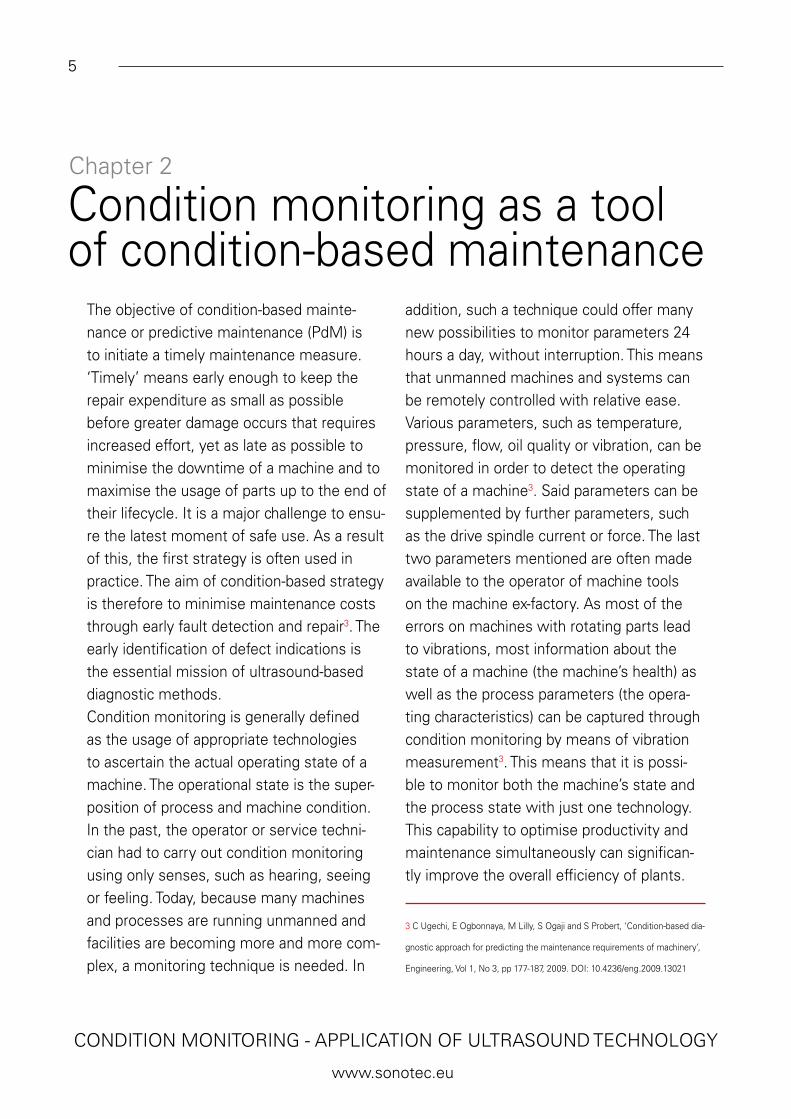
The piezocomposite material used in this work was manufactured using ‘dice-and--fill’ technology (Figure 5). This demanding manufacturing technique was established in SONOTEC in 2008. Piezoceramic plates (for example lead zirconate titanate (PZT)) are partially cut by a wafer dicing machine in two directions under an angle of 90°. The gaps are filled with polyurethane or epoxy resin. After hardening, the plate is ground to its final thickness. Finally, the composite is metallised and polarised.This manufacturing process is com-plex and features several steps with different difficul-ties. This results in a variety of possibi-lities, enabling new transducer proper-ties. Variations are possible through changes in the type of piezocera-mic, type of plastic matrix, pitch and arrangement of
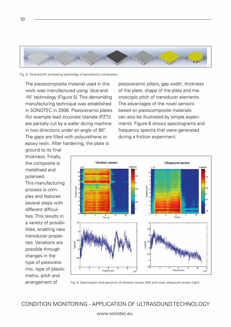
piezoceramic pillars, gap width, thickness of the plate, shape of the plate and ma-croscopic pitch of transducer elements.The advantages of the novel sensors based on piezocomposite materials can also be illustrated by simple experi-ments. Figure 6 shows spectrograms and frequency spectra that were generated during a friction experiment.
Fig. 5: ‘Dice-and-fill’ processing technology of piezoelectric composites
Fig. 6: Spectrogram and spectrum of vibration sensor (left) and novel ultrasound sensor (right)

11
CONDITION MONITORING - APPLICATION OF ULTRASOUND TECHNOLOGY
www.sonotec.eu
The experiment consisted of two dif-ferent sensors, which were fixed on a steel tube. A conventional high-frequency vibration sensor was compared with one of the new broadband ultrasonic sensors. A stimulation with sandpaper was used as the source of structure-borne sound. In the spectrograms, this reciprocation is recognisable between two and seven seconds. The frequency spectra are each calculated from a time window within this
time range. Both the spectrograms and the spectra clearly show the differences between the two types of sensor. The vi-bration sensor has significant resonances above 60 kHz, but the ultrasonic sensor does not. From the broadband excitation by friction, the relatively smooth frequen-cy characteristics of the novel sensors can be displayed particularly well. The possi-bility of linearisation of this characteristic can be derived from this.
Chapter 6
Application examplesWafer dicing saw
The aim of this example is to present the opportunity to use novel ultrasound sensors for condition monitoring of the processing of ceramic parts using pre-cision wafer dicing machines. The moti-vation is the general optimisation of the dicing processes, especially of so-called ‘hard-to-cut’ materials, or condition mo-nitoring of the processing of very expen-sive parts. The drive spindle of the dicing machine was equipped with ultrasound sensors based on piezocomposites. The thickness resonance frequency of the-se sensors is about 1 MHz. The signals were acquired with the data acquisition card DT 9847-2-2 (Data Translation) and analysed using MATLAB from Math-
works. A sampling rate of 216 kHz was applied. Figure 7 shows two of the novel sensors, as well as the drive spindle of the dicing machine equipped with the sensors.The example of the wafer dicing machi-ne is an interesting application because of the special drive spindles that are used in these machines. The high-speed spindles with a rotational speed of up to 60,000 r/min are air-bearing spindles with brushless motors. Hence, there is no direct mechanical coupling between the rotating and stationary parts within the process. Additionally, the air bearing permanently causes acoustic emission by the blowout of air.

12
CONDITION MONITORING - APPLICATION OF ULTRASOUND TECHNOLOGY
www.sonotec.eu
Fig. 7: Novel sensors for condition monitoring (left) and equipped dicing machine (right)
A standard dicing process of three ceramic discs fixed in one row was analysed (Figure 8). The process needs about six seconds for each cut line. First, the drive spindle moves down (z-axis direction). The actual cutting process follows as the second step. At first glance, the time signal does not provide any valuable information for process control.
Therefore, time-frequency signal processing has to be applied. Within the spectrogram (Figure 8, right) the whole dicing process is displayed. Some fixed low frequencies were measured constantly. These are an effect of the rotating spindle with a fixed rotational speed of 30,000 r/min and the turbulences at the air bearing outlet superpositioned by
Fig. 8: Schematic workflow and time signal (left) and frequency spectrogram (right)

13
CONDITION MONITORING - APPLICATION OF ULTRASOUND TECHNOLOGY
www.sonotec.eu
Fig. 9: Photograph of partly processed ceramic plate
by effects from cooling water spray. At the be-ginning and at the end of the cut (step 1 and step 3) the very high accelera-tion of the z-axis results in high amplitudes over a width frequency range of a maximum of 5 kHz. During the cut (step 2) the processing of the three di-scs results in reproducible changes of the spectrum at different frequencies. The highest amplitudes were generated around 20 kHz, which is a good indication that con-dition monitoring in the ultrasonic frequency range could work well. With this result it is possible to monitor changes in the proces-sing parameters – for example, the higher the feed speed, the higher the amplitude in the ultrasonic frequency range.In the following example, results are shown for a test series for feed speed optimisation. While increasing the feed speed from one cut line to the next, a ceramic plate was processed. At present, the value of spindle driving current provides the only informa-tion about the process state. Due to the very small changes in spindle drive current compared to the changes in feed speed, the monitoring results are insufficient. Much more information can be acquired with the ultrasound sensors placed at the drive spindle. Figure 9 shows a photograph of the
partly cut plate. A broken ceramic lamella is visible in the middle of the last cut line. Six cut lines prior to this, the first traces of damage can be observed at the bottom of the cutting grooves, meaning that the dicing process was already in a critical state.This raises the question of whether or not is it possible to detect this critical state of process. The following results (Figure 10) show that this will be possible with the use of a spectral time-frequency data evaluation. In the frequency spectrogram, first hints can be found at the lower frequency range, up to 5 kHz.

14
CONDITION MONITORING - APPLICATION OF ULTRASOUND TECHNOLOGY
www.sonotec.eu
Fig. 10: Time signal (top left); spectrogram (top right); and zoom of spectrogram (bottom)
The higher friction at the critical process state, and especially the breakage of the lamella, causes changes in the frequency spectrum of the signals.At the measuring time of 2.3 s, some resonance lines are interrupted. This tran-sient event was detected by the sensors and could be caused by the breakage of the ceramic lamella, as shown in Figure 9. The geometric position of the breakage can be approximately assigned to the transient event seen in the spectrogram. A precise assignment is not possible at the moment because there is no trigger signal from the
moving machine axis that can be used for synchronising the measurment time axis. Also, a detailed interpretation of the phy-sical and technical effects has to be part of further studies and will be published in future articles. In conclusion, it can be stated that the novel ultrasound sensors based on piezocomposites can be used very effectively for condition monitoring of dicing processes.

15
CONDITION MONITORING - APPLICATION OF ULTRASOUND TECHNOLOGY
www.sonotec.eu
Ball bearing defect detection
A bearing test stand was used for investi-gations of bearing diagnosis with the new SONAPHONE ultrasonic detector. Ball bearings of type 6002 were prepared with various test faults for damage simulation. Figure 11 shows an example of the hatched area in the ball raceway of the outer ring. Both the raceway of the inner ring and the balls can be prepared by laser engraving. The aim of this method is to use a reprodu-cible preparation technique. This is impor-tant so that the condition at the beginning of the intended wear can be produced as often as needed. During operation, this simulated bearing damage generates vi-brations and structure-borne sound. Figure 12 shows an up-and-down run on a new ball bearing (left) as well as on a prepared bearing (right). The defective bearing can be differentiated from the new bearing by means of the sound level difference as well as by optical evalu-ation of the spectrogram. In the case of the prepared bearing, even ultrasound is detected over the com-plete frequency range of the SONAPHONE up to 100 kHz. Figure 11 shows screen shots of the Data-Viewer software running on a PC. The sound level is displayed at the top and
the spectrograms of the measuring time are shown at the bottom.The robustness of the broadband ultrasound technology can also be shown in the present example for bearing diagno-sis. It can be seen in the spectrograms that there are frequency ranges in which almost no sound energy is emitted. Through the use of classical narrowband testing tech-nology, the result depends highly on the superposition of the frequency ranges of the maximum sensitivity of the test tech-nology and the frequency characteristics of the bearing damage. The approach of the broadband measurement technique and broadband data evaluation leads to a re-markable improvement in reliability during ultrasonic testing in the technical diagnosis.
Fig. 11: Ball bearing outer ring, test fault engraved by a laser beam

16
CONDITION MONITORING - APPLICATION OF ULTRASOUND TECHNOLOGY
www.sonotec.eu
Chapter 7
ConclusionsThe application of ultrasound in maintenance was classified within the envi-ronment of modern maintenance methods at the beginning of this article. In the area of condition monitoring in particular, the ultrasound technique makes a significant contribution to the early detection of errors. The development of a new testing device and first application examples were briefly presented. The advantages of the broadband measuring process, including the use of novel ultrasound sensors with piezocompo-site material at the heart of the transducers, were described. The broadband data analy-sis and the resulting increased robustness of the test results were highlighted.
AcknowledgementsParts of this work have been supported by the Federal Ministry of Education and Re-search UMKlaD (BMBF, programme: kMU--innovativ, project: 01IS15051A).
Fig. 12: Up-and-down run at the test bench. New bearing (left) and bearing with damage (right)