Embed Size (px)
Citation preview

Condenser Cleaning, NDE and Leak Detection Part I: Condenser Cleaning

© 2011 Conco Systems, Inc.
What is Total Condenser Performance™ ? Achieving the perfect balance of condenser efficiency and reliability is achievable through effective cleaning and testing. Implementing these strategies will maximize MW output and minimize condenser related outages during your operating cycle.
Introduction

© 2011 Conco Systems, Inc.
Three sections: Fouling and Condenser Cleaning Air and Water In-leakage Testing Eddy Current Testing
Introduction

© 2011 Conco Systems, Inc.
Condenser Fouling and Cleaning
o Fouling of tube surfaces o Tube materials and their corrosion characteristics o Prevention of tube fouling o Deposit sampling o Cleaning options for fouled tubes o Innovation of cleaning technology o Selecting a cleaning procedure o Cases

© 2011 Conco Systems, Inc.
Fouling of Tube Surfaces
Fouling of tube surfaces cause a variety of challenges for your condenser to overcome:
o Loss of heat transfer o Under-deposit corrosion

© 2011 Conco Systems, Inc.
Condenser Tube Fouling
The Fouling 5 o Deposition or Particulate o Scaling or Crystallization o Microbiological o Debris and Macrofouling o Corrosion and Corrosion Product
Let’s look closer at each fouling category

© 2011 Conco Systems, Inc.
o Particulate debris that settles on the tube surface o Natural sediment, bio-growth, solids precipitated
as particulates o Result of low flow conditions o Stimulates under-deposit corrosion
Deposition / Particulate Fouling
Fresh water silt removed from condenser

© 2011 Conco Systems, Inc.
o Saturation point of dissolved constituents in the cooling water is exceeded
o Scales form under higher temperature conditions
o Detrimental to heat transfer o Under-deposit corrosion o Removal of scale is required
Scaling / Crystallization Fouling
Scaling distributed throughout condenser
© 2011 Conco Systems, Inc.
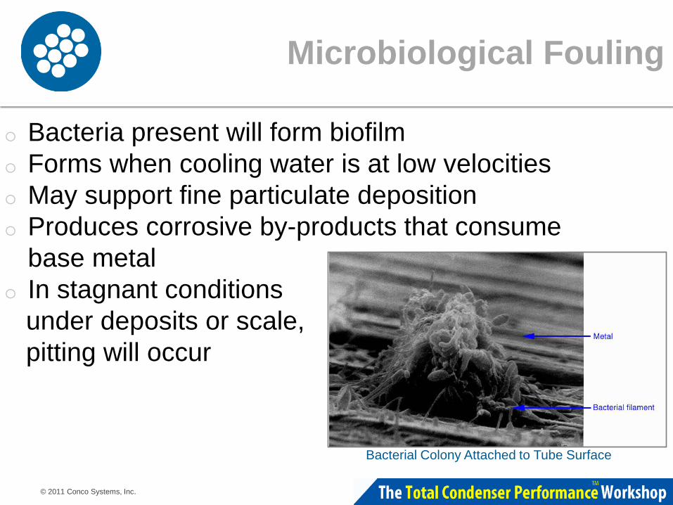
Microbiological Fouling
o Bacteria present will form biofilm o Forms when cooling water is at low velocities o May support fine particulate deposition o Produces corrosive by-products that consume
base metal o In stagnant conditions under deposits or scale, pitting will occur
Bacterial Colony Attached to Tube Surface

© 2011 Conco Systems, Inc.
Debris and Macrofouling
o Condenser inlet tubesheet and tubes • Debris • Aquatic animals, shell fish
o Partial flow blockage • Slower flow allowing particulates to accumulate • Local flow around the item may cause erosion-corrosion
Flow reduction due to macrofouling

© 2011 Conco Systems, Inc.
Corrosion Product
o Insert corrosion product description here.
Corrosion product on copper-alloy tube

© 2011 Conco Systems, Inc.
Fouling Characteristics: Copper Alloy Tubing
o Tubing • Admiralty Brass • Aluminum Brass • Copper-Nickel
o Corrosion Characteristics • Crevice corrosion, pitting • Dealloying-dezincification or
denickelification • Erosion-corrosion
• Inlet end • Down tube
• Ammonia corrosion, stress cracking corrosion
Copper & Copper Alloy Tubing

© 2011 Conco Systems, Inc.
Fouling Characteristics: Stainless Steel Tubing
o Tubing • 304 • 316
All 300 series, lean and intermediate duplexes are susceptible to:
• Crevice corrosion, under-deposit corrosion, pitting
• Microbiological influenced corrosion (MIC)
• Chloride pitting
Corrosion Resistant • SEA-CURE®
• AL6XN

© 2011 Conco Systems, Inc.
Fouling Characteristics: Titanium Tubing
o Corrosion resistant o Still must be kept clean

© 2011 Conco Systems, Inc.
o pH control o Scale inhibitors o Dispersants o Biocides o Corrosion inhibitors
Chemical Fouling Prevention

© 2011 Conco Systems, Inc.
Mechanical Fouling Prevention
o Screens o Filtration o Cleaning systems o Increasing flow

© 2011 Conco Systems, Inc.
o Back pressure deviation o Cleanliness factor o Inlet and outlet cooling water temperature
differential o Heat rate o Megawatt output
Performance Indicators

© 2011 Conco Systems, Inc.
o Increased unit heat rate o Increased losses to cooling water o Increased CO2 or NOx emissions o Reduced generation capacity o Tube failures lead to damage in other equipment
Economic Consequences

© 2011 Conco Systems, Inc.
Increased backpressure can be attributed to fouled and blocked condensers and excess air inleakage into the condenser In this section of the workshop, let’s discuss how Conco mechanical tube cleaning can restore condenser performance and reliability
Potential Causes for Performance Loss

© 2011 Conco Systems, Inc.
C4S C3X C4SS Cal-Buster H-Brush Type P XL Brush C3S C2X
Industry Standard Tube Cleaners
SSTB

© 2011 Conco Systems, Inc.
Hex Cleaner
Stainless Steel Tube Cleaning Brush
Innovations in Tube Cleaners
Cal-Buster™

© 2011 Conco Systems, Inc.
Spring-Loaded Cleaner in Action

© 2011 Conco Systems, Inc.
Element %
Manganese 10-20
Aluminum 0.1-1.0
Potassium 0.1-1.0
Iron 5-10
Phosphorus 0.1-1.0
Titanium 0.1-1.0
Silicon 5-10
Sulfur 0.1-1.0
Nickel 0.1-1.0
Calcium 1-5
Chlorine 0.1-1.0
Elements <0.01% Not Listed
Loss on ignition Not Listed
Results of Elemental Analysis

© 2011 Conco Systems, Inc.
Dry Weight g
Density g/sq.ft.
217.30 17.5945
129.89 10.5170
126.12 10.2118
111.10 8.9956
98.62 7.9851
95.56 7.7374
93.54 7.5738
36.37 2.9448
25.26 2.0452
4.95 0.4007
1.79 0.1449
Tube Sample Deposit Density

© 2011 Conco Systems, Inc.
Tube Cleaning Variables
o Cooling Water System o Tube Material o Deposit Type(s) o Corrosion o Tube Quantity and Size o Schedule o Tube Cleaning System

© 2011 Conco Systems, Inc.
Tube Quantity and Size
Quantity o How many water boxes? o How many tubes? o Main Section? o Air Removal Section?
Size o Outer Diameter (O.D.) o Gauge (BWG) or (I.D.) o Length o Other considerations oCoatings o Inserts
© 2011 Conco Systems, Inc.
Schedule
o Unit Size o Availability o Peak or off peak demand o On-line or reduced load o Time requirement for cleaning

© 2011 Conco Systems, Inc.
o Select the most effective tube cleaner.
o Insert the tube cleaners into each tube.
o Utilizing the water gun and pump system the cleaners are “shot” through the tubes.
Tube Cleaning

© 2011 Conco Systems, Inc.
Water Gun Mobile Pump System
Water Gun and Pump System

© 2011 Conco Systems, Inc.
Tube Cleaner in Action

© 2011 Conco Systems, Inc.
Expectations
o Performance improvement o Most effective deposit removal o Corrosion protection o Remove obstructions o Clean each and every tube, maintain
consistency throughout o Smooth tube surface

© 2011 Conco Systems, Inc.
o Minimizes downtime: 5000+ tubes per shift
o Cleaners are effective on all types of fouling: • Fouling Deposits (better heat transfer) • Corrosion Product (tube failure mechanism) • Physical Obstructions (improved performance) • Improved Surface Roughness (improved flow rate)
Mechanical Cleaning Summary

© 2011 Conco Systems, Inc.
Additional Benefits
o Economic Benefit • Immediate Return on Investment • Reduced Costs
o Recovery of lost megawatts or increased generation capacity
o Fuel savings o Reduction in CO2 emissions o Extended useful life of the condenser

© 2011 Conco Systems, Inc.
MW loss o 8760 hrs./yr. o Capacity Factor o Price per MWh o MW
Heat Rate o Assume the reduction of .3 hg
in condenser backpressure is equivalent to approximately 10% improvement in condenser performance
o Each 10% improvement in condenser performance correlates to a 1% improvement in heat rate (10,000 btu/kWh) or MW output
Ex: 8760 x .70 x $60.00 x 3 MW = $1,103,760.00 Ex: .6 hg = 20% CF = 2% HR = 2 MW
Ex: 8760 x .70 x $60.00 x 2 MW = $ 735,840.00
Quick Calculations

© 2011 Conco Systems, Inc.
Omaha Public Power
18,390 lbs. of CaCO3 scale removed

© 2011 Conco Systems, Inc.
River Bend Nuclear
River Bend Nuclear • 936 MW BWR • River water • 16,395 Brass tubes • Macro Fouling: Tower Fill,
Sponge Balls Results
• Recovered 2.5 MW per hour/60 MW per day
• Cleaning cost recouped in 2 weeks

© 2011 Conco Systems, Inc.
Tube Cleaning Wrap Up
o The return on investment by having deposits removed before they cause major loss of heat transfer, tube corrosion or ultimately tube failure can be significant.
o Not only are there losses in performance to consider, but major equipment repairs often follow tube failures due to cooling water contaminants in the boiler or turbine.

© 2011 Conco Systems, Inc.
Gary Fischer National Sales Manager CONCO Systems Services Industrial 1-800-345-3476 or +1-412-828-1166 [email protected]
Questions?
|

Condenser Cleaning, NDE and Leak Detection Part II: Leak Detection

© 2011 Conco Systems, Inc.
o Why perform tracer gas leak detection? o When to perform leak detection o Benefits of tracer gas leak detection o Selecting the ideal tracer o Air inleakage detection o Condenser tube leak detection
This Presentation Will Cover

© 2011 Conco Systems, Inc.
Leakage of air or water into the condenser will adversely affect plant efficiency, reliability and availability o Increased plant heat rate o Increased risk to turbine components o High levels of dissolved O2 in feedwater means
increased deterioration of boiler and feed systems
Why Plants Need to Test

© 2011 Conco Systems, Inc.
Proactive Testing o Routine inspection to understand where potential
failures will occur o Before an outage so components in need of repair are
scheduled for repair o After an outage to insure all repairs were made
successfully Reactive Testing o Emergency inspections as a result of catastrophic
failure or because inleakage has exceeded the air removal system capability
When Plants Need to Test

© 2011 Conco Systems, Inc.
Condenser backpressure climbing • Other factors such as fouled condenser tubes can
contribute to increased backpressure, however, an air inleakage inspection should be the first option as it can be performed online and for minimal cost
Dissolved O2 levels increasing Increased usage of phosphates
Condenser Leakage Indicators

© 2011 Conco Systems, Inc.
o Inleakage to shell o Rupture discs o Shaft seals o Test probe penetrations o Man ways o Vacuum pumps o Flanges o Bolt holes
Sources of Air Inleakage
Rupture Disc
Vacuum Pump Shaft Seal

© 2011 Conco Systems, Inc.
o Water box flanges o Faulty tube plugs o Leaking hotwell components o Through-wall penetrations o Tube to tubesheet joints
Sources of Water Inleakage
Through-wall penetrations
Tubesheet joints

© 2011 Conco Systems, Inc.
Condenser Penetrations

© 2011 Conco Systems, Inc.
Crossover Bellows

© 2011 Conco Systems, Inc.
Test Probe Penetrations

© 2011 Conco Systems, Inc.
LP Turbine Shaft Seal

© 2011 Conco Systems, Inc.
Heater Drain Pump Shaft Seal

© 2011 Conco Systems, Inc.
Choosing the most appropriate tracer gas for your site specific conditions is important. Some contractors may only have expertise with one type of gas, so choose wisely as a less ideal tracer will cost you time and money o Helium o Sulfur Hexafluoride (SF6)
Choosing the Ideal Tracer

© 2011 Conco Systems, Inc.
Air inleakage • Total amount of air inleakage • Characteristics of specific leakage • Leak quantification • Dissolved oxygen considerations
Condenser tube leakage
• On-line injections • Tubesheet inspections • Leak characteristics
Tracer Gas Selection Criteria

© 2011 Conco Systems, Inc.
The helium mass spectrometer was developed to find extremely small leaks in the gas diffusion process in the Manhattan Project during WWII o Quick and reliable, non-toxic, non-hazardous o Detection range, 1 part per 10 million above
background (~5ppm) o Suitable for “most” leaks
Tracer Overview: Helium

© 2011 Conco Systems, Inc.
In 1976, SF6 was used as an airborne tracer to track plume migration and EPRI explores its use as a tracer in power plant leak detection o Inert, odorless, incombustible o Detection range is 1 part per 10 billion o Non-reactive to H20 o Detection accuracies can be 40 times greater
than those obtained using helium o Suitable for small or hard to locate leaks
Tracer Overview: SF6

© 2011 Conco Systems, Inc.
System Comparisons
Fluorotracer™ Analyzer Mass Spectrometer

© 2011 Conco Systems, Inc.
Unit Operating Conditions
A minimum of 15% turbine power is required for successful leak detection to occur
Steam Flow: • Crucial to successful leak detection • Clears tracer out of condenser • Response time is quicker • Analyzer recovery time is quicker • Without Steam flow: Tracer gas background will
continue to rise, making isolation of leak virtually impossible

© 2011 Conco Systems, Inc.
Typical Leak Response
ResponseTime
InitialResponse
Rate
of R
espo
nse
ClearoutTime
Base Line
Magnitudeof Response
GasRelease

© 2011 Conco Systems, Inc.
Air Inleakage Detection

© 2011 Conco Systems, Inc.
o Detecting tube leaks o Use of plenums o Reduce size of plenum o Single tube shooter
Condenser Tube Leak Inspection
Mid-Sized Plenum
Large-Sized Plenum

© 2011 Conco Systems, Inc.
Tube Inspection Set Up
Inlet Water Box Outlet Water Box
Air Removal System Condenser Off Gas
Gas Analyzer Sample Conditioning Sampling Pump
Air Mover Technician in water box
controlling tracer gas release with plenum
Technician at analyzer monitoring gas detection
Exhaust

© 2011 Conco Systems, Inc.
SF6 allows for online injection into water boxes under full load to determine leaking bundle
• Fluorotracer™ Analyzer is sampling the off-gas • SF6 cylinder is connected to injection point below the
waterline • Gas injected into circulating water @ ~10 cfm for 30
seconds • Capable of identifying 1gpd leak
Online Injection of SF6 Tracer

© 2011 Conco Systems, Inc.
o Air and water inleakage continues to cost generators hundreds of thousands to millions of dollars annually
o Condenser tube leaks cause more than 6,000 forced outages annually and rank as one of the highest concerns among plant chemists
o In addition to reactive leak detection, a proactive regimen of testing can keep total air inleakage in check
o ROI for leak detection maintenance dollars spent are usually in the 1000% + range, so don’t wait!
In Closing

© 2011 Conco Systems, Inc.
Eric H. Fayard Director, Technical Marketing CONCO Systems Services Industrial 1-800-345-3476 or +1-412-828-1166 [email protected]
Questions?
|

Condenser Cleaning, NDE and Leak Detection Part III: NDE with Eddy Current

© 2011 Conco Systems, Inc.
Eddy Current Testing (ECT) Is a nondestructive test technique based on inducing electrical currents in the material being inspected and observing the interaction between those currents and the material.
Eddy Current Testing
Eddy currents are generated by electromagnetic coils in the test probe, and monitored simultaneously by measuring probe electrical impedance.

© 2011 Conco Systems, Inc.
What Can be Detected?
o Various defects o Pitting o Cracking o Erosion o Corrosion o Grooving o Dents

© 2011 Conco Systems, Inc.
Why Eddy Current Test?
o To decrease forced outages due to tube failure o To minimize losses associated with availability o Early detection of potential failure mechanisms o Estimate remaining useful life of the tubes o Planning and budgeting / equipment
replacement o Summary of overall unit condition o Baseline and annual trending reviews

© 2011 Conco Systems, Inc.
o Technicians certified in accordance with the American Society of Nondestructive Testing standards.
o Quality assurance program that meets your company or industry guidelines.
o Current equipment calibration. o Clean tubes.
Testing Requirements

© 2011 Conco Systems, Inc.
o Multi-frequency • Corestar Omni • Zetec MIZ 28
o Probes o Computerized Data
Interpretation
Typical Multi-Frequency Testing Equipment

© 2011 Conco Systems, Inc.
Two Modes: Absolute and Differential
o The need for testing in two modes. o Gradual Wall thinning detected in absolute
mode. • Steam erosion • Inlet end erosion
o Small defects such as pitting and cracking can
be detected in differential mode.

© 2011 Conco Systems, Inc.
Multiple Frequency Benefits
Higher Frequencies • e.g. Stainless Steels
(.028) • Near surface flaws • ID Pitting
Lower Frequencies • e.g. Brass / Copper Alloys
(.049) • Subsurface Flaws • Severe Pitting
© 2011 Conco Systems, Inc.
The Necessity of Multiple Frequencies
o Identification of ID and OD pitting simultaneously o To achieve complete depth of penetration of the
tube wall o Most accurate characterization of defects. o Allows for mixing out of signals that represent
support plates (non defects) o Allows for discrimination of metallic deposits that
may remain

© 2011 Conco Systems, Inc.
A Bit More on Depth of Penetration
Effective Depth of Penetration • “The minimum depth beyond which a test system can
no longer detect a further increase in specimen thickness.”
• The penetration potential of a frequency is limited!

© 2011 Conco Systems, Inc.
And Why Depth of Penetration is so very important
Without the benefits that multi-frequency full depth of signal penetration, this tube would have simply revealed a pit, rather than a tube that would have caused a forced outage during the next operating cycle
Cross-sectional view of cavern

© 2011 Conco Systems, Inc.
Two Primary Challenges
Surprisingly, one of the primary challenges for achieving the most accurate test results, is based on the cleanliness of the tube being tested.
“Effectively cleaned tubes allow for; o Optimal “Fill Factor” 80% or greater o Improved probe speed o Ideal centering of probe head in tube o Reduced chance of damaging probes causing
additional expense/time for plant

© 2011 Conco Systems, Inc.
Impact of Ineffective Cleaning on ECT Results
Row 16, Tube 14 Row 16, Tube 14
Tube Ineffectively cleaned on left Same tube following effective cleaning

© 2011 Conco Systems, Inc.
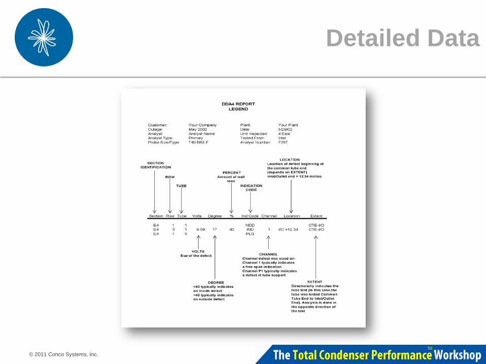
The Report
o Executive Summary of condition o Detailed data on each tube tested o Results o Color coded tubesheet map o On site analysis option
© 2011 Conco Systems, Inc.
Detailed Data

© 2011 Conco Systems, Inc.
Tubesheet Map
A color-coded tube sheet map can be produced to quickly identify problem areas Plugged Tube 80-100% Wall Loss 60-79% Wall Loss 40-59% Wall Loss 20-39% Wall Loss

© 2011 Conco Systems, Inc.
Proactive Tube Plugging
Plugging tubes before they cause an unplanned outage is the goal A good rule of thumb is to maintain enough plugs in stock equal to 2% of your tube quantity. A 10,000 tube unit should have 200 plugs on hand for new plugging as well as replacement for worn or damaged plugs

© 2011 Conco Systems, Inc.
Summary
o Reduced number of forced outages due to tube leaks
o Early detection of potential failure mechanism o Estimate remaining useful life of the tubes o Summary of overall unit condition o Improved reliability and availability

© 2011 Conco Systems, Inc.
Gary Fischer National Sales Manager CONCO Systems Services Industrial 1-800-345-3476 or +1-412-828-1166 [email protected]
Questions?
|