Embed Size (px)
Citation preview
Concurrent Active Piezoelectric Control and Energy Harvestingof Highly Flexible Multifunctional Wings
Natsuki Tsushima∗ and Weihua Su†
University of Alabama, Tuscaloosa, Alabama 35487-0280
DOI: 10.2514/1.C033846
Both active actuation and energy harvesting of highly flexible wings using piezoelectric transduction are studied in
this paper. The piezoelectric effect is included in a strain-based geometrically nonlinear beam formulation. The
resulting structural dynamic equations for multifunctional beams are then coupled with a finite-state unsteady
aerodynamic formulation, allowing for piezoelectric energy harvesting and actuation with the nonlinear aeroelastic
system. With the development, it is possible to provide an integral aeroelastic and electromechanical solution of
concurrent active piezoelectric control and energy harvesting for wing vibrations, with the consideration of the
geometrical nonlinear effects of slender multifunctional wings. In this paper, linear quadratic regulator and linear
quadratic Gaussian controllers are developed for the active control of wing vibrations. The controllers demonstrate
effective gust alleviation capabilities. Furthermore, concurrent active vibration control and energy harvesting can
also be realized for the multifunctional wings with embedded piezoelectric materials. From this numerical study, the
impact of the piezoelectric actuator and energy harvester placement on wing performance is benchmarked.
Nomenclature
A = system matrix in state-space equationA = cross-section area of piezoelectric layer, m2
a0 = local aerodynamic frame, with a0x axispointing towing tip anda0y axis alignedwithzero lift line of airfoil
a1 = local aerodynamic frame, with a1y axisaligned with airfoil motion velocity
B = body reference frameB = control matrix in state-space equationBvh, Bva = piezoelectric coupling matrix for harvester
and actuatorBcsvh = cross-sectional piezoelectric coupling ma-
trix�B = electric displacement, C∕m2
BF, BM = influence matrices for distributed forces andmoments
bc = semichord of airfoil, mbp = chordwise width of piezoelectric layer, mC = coefficient matrix for state vector in state-
space output modelCp = capacitance of energy harvesting system, FD = coefficient matrix for control input in state-
space output model�D = piezoelectric material stiffness matrixd = distance of midchord in front of beam
reference axis, mE = electric field, V∕me = piezoelectric coupling, C∕m2
e31 = transverse piezoelectric coupling, C∕m2
e36 = piezoelectric coupling for induced shearstress, C∕m2
Fi = influence matrices in inflow equations withindependent variables (with i equal to 1, 2,and 3)
Fia,Mia = piezoelectric induced force and moment inbeam coordinate (with i equal to 1, 2, and 3)
Fdist, Fpt = distributed and point forcesG = coefficient matrix for disturbance (process
noise) in state-space system modelg = gravity acceleration column vector, m∕s2H = coefficient matrix for disturbance (process
noise) in state-space output modelh = absolute positions and orientations of beam
nodesi = electric current in circuit of energy harvest-
ing system, AJ, Js, Jc = total system, state, and control cost functionsJhε, Jpε, Jθε = Jacobian matrixK = control gainlmc, mmc, dmc = aerodynamic lift, moment, and drag on
airfoil about its midchordMFF, CFF, KFF = generalized inertia, damping, and stiffness
matrices�MFF, �CFF, �KFF = linearized generalized inertia, damping, and
stiffness matricesMs, Cs, Ks = discrete inertia, damping, and stiffness
matrices of whole systemMdist,Mpt = distributed and point momentsN = influence matrix for gravity forcen = sensor noisepw = position of w frame resolved in B frameQ, R = penalty matrix for control input and state
vectorQe = total charge accumulated over electrodes, CRe = resistance of energy harvesting circuit, ΩRF = components of generalized load vectorRaero
F∕λ0 = derivative of aerodynamic load vector withrespect to inflow states
r = weighting parameter of control penaltiess = beam curvilinear coordinate, msp = spanwise length of piezoelectric layer, mTs, Te = transformation matrices of compositestp = thickness of piezoelectric layer, mU∞ = aircraft trim velocity or freestream
velocity, m∕su = control input to system plant
Presented as Paper 2016-0715 at the 57th AIAA/ASCE/AHS/ASCStructures, Structural Dynamics, and Materials Conference, San Diego, CA,04–08 January 2016; received 25 December 2015; revision received 4 July2016; accepted for publication 5 July 2016; published online 3 October 2016.Copyright © 2016 by Natsuki Tsushima and Weihua Su. Published by theAmerican Institute of Aeronautics and Astronautics, Inc., with permission.Copies of this paper may be made for personal and internal use, on conditionthat the copier pay the per-copy fee to the Copyright Clearance Center (CCC).All requests for copying and permission to reprint should be submitted toCCCat www.copyright.com; employ the ISSN 0021-8669 (print) or 1533-3868(online) to initiate your request.
*Ph.D. Student, Department of Aerospace Engineering and Mechanics;[email protected]. Student Member AIAA.
†Assistant Professor, Department of Aerospace Engineering andMechanics; [email protected]. Senior Member AIAA.
724
JOURNAL OF AIRCRAFT
Vol. 54, No. 2, March–April 2017
Dow
nloa
ded
by U
NIV
ER
SIT
Y O
F A
LA
BA
MA
on
Apr
il 19
, 201
7 | h
ttp://
arc.
aiaa
.org
| D
OI:
10.
2514
/1.C
0338
46

v = voltage of multifunctional system, VWext,W int = external and internal virtual workw = disturbance to system (process noise)w = local beam frame resolved in B framex = state vector of system plantx̂ = state vector estimate of system planty = output vector of system plant_y, _z = airfoil translational velocity components
resolved in local aerodynamic frame, m∕szp = distance between elastic axis of beam and
piezoelectric layer, m_α = airfoil angular velocity about a0x axis, rad∕sε = total beam strain vectorεx = extensional strain in beam membersε0 = initial beam strain vector�ε = material strain in piezoelectric constitutive
relationζ = permittivity, F∕mθ = rotations of beam nodes, radκx, κy, κz = torsional, flat bending, and edge bending
rates of beam members, 1∕mλ = inflow states, m∕sλ0 = inflow velocities, m∕sρ = air density, kg∕m3
�σ = material stress in piezoelectric constitutiverelation, Pa
1, 2, 3 = beam coordinate in composite material
Subscripts
eq = reference nonlinear equilibrium state inwhich linearization is performed
hε = h vector with respect to strainpε = nodal position pw with respect to strain εθε = nodal rotation θ with respect to strain ε
I. Introduction
U NMANNED aerial vehicles (UAVs) have been developed fordifferent applications for several years. For example, the U.S.
Air Force has been working on a new generation of intelligence,surveillance, and reconnaissance platform called Sensorcraft [1].On the other hand, NASA initiated the Environmental ResearchAircraft and Sensor Technology program, the aim of which was todevelop UAVs capable of very high-altitude and long-enduranceflights for atmospheric research purposes. Under this program, anevolutionary series of unmanned aircraft (Pathfinder, Pathfinder-Plus, Centurion, and Helios Prototype) was developed byAeroVironment, Inc. These high-altitude long-endurance (HALE)aircraft feature high-aspect-ratio slender wings with a lowstructural weight fraction. The slender wings may undergo largedeformations under normal operation conditions, exhibitinggeometrically nonlinear behaviors [2–5]. Therefore, geometricalnonlinearity must be properly taken into account in the aeroelasticmodeling of highly flexible vehicles [2,3,6–8].Meanwhile, different techniques have been developed and applied
to improve the aircraft performance and to facilitate the long-endurance flight, of which wing morphing has become a dynamicresearch topic. The technique is hoped to improve the flightperformance under different flight conditions, in which traditionalcontrol surfaces are less effective. It may also be possible to provideextra control authority in poor flight conditions. An early concept ofwing warping was employed in the aircraft built by the Wrightbrothers, which was later replaced by discrete control surfaces due tothe lack of the structural stiffness. In recent studies of the activeaeroelastic wing (AAW) [9,10], a set of control surfaces was used toproduce the favorable wing aeroelastic deformation so as to improvethe aircraft flight performance, instead of directly generating themaneuver loads. The studies showed promising benefits of the AAWtechnology in weight, drag, and control performance perspectives.However, for better performance of morphing wings, one needs to
apply the proper actuation mechanism and scheme, with sufficientenergy to drive the mechanism.Additionally, multifunctional structural technologies [11] are
being developed, which may bring revolutionary changes to aircraftstructures. These structures are capable of performing multipleprimary functions and can potentially improve the aircraftperformance through consolidation of subsystem materials andfunctions [11,12]. The employment of the wing morphing conceptand multifunctional structural technologies may create new aircraftplatforms with enhanced effectiveness and improved capability ofoperation. Active materials, such as anisotropic piezocompositeactuators [13,14], may be used to build multifunctional structures. Infact, onemay take advantage of piezoelectric transducers to fulfill thedual functions of both actuation and energy harvesting [15]. Actually,for HALE aircraft in which energy usually constrains their flightrange and endurance, the extra energy can be accumulated from theambient with different mechanisms, such as the piezoelectric effect[16], thermoelectric effect [17], pyroelectric effect, photovoltaiceffect, magnetostatic effect, etc. Among them, mechanical vibrationsof structural components have been considered as a major energysource [18], with piezoelectric materials embedded into wingstructures as sensors and harvesters. This is essentially an inversedapplication of the piezoelectric effect involved in the wing actuation.To explore the approaches to model the electromechanical behaviorof piezoelectric transducing, many research groups from differentfields have developed various prediction models. Early studies ofpiezoelectric transducing have modeled the piezoelectric transducerusing a simplified lumped model with bending vibrations [19,20].Even though the approach was effective, the lumped model camewith some disadvantages, such as the oversimplification of the realphysics. To improve the accuracy, some distributedmodels have beenapplied in the subsequent studies. For example, Bilgen et al. [21]modeled the cantilever beam with embedded piezoelectric materialsusing the linear Euler–Bernoulli beam theory and applied thisapproach to the piezoelectric transducing and gust alleviation of asmall UAV [22]. Sodano et al. [23] developed a model of thepiezoelectric power harvesting device based on the works of Hagoodet al. [24] and Crawley and Anderson [25]. They used energymethods to develop the constitutive equations of a bimorphpiezoelectric cantilever beam. The model was solved with theRayleigh–Ritz procedure. Erturk and Inman [26] providedcorrections and necessary clarifications for physical assumptions inpiezoelectric transducing. More recently, Anton et al. [12] presentedthe investigation of a multifunctional wing spar for small UAVs.On the other hand, the piezoelectric actuationwas implemented for
aerospace applications in many ways. For example, Bent et al. [27]developed the actuator equations for piezoelectric fiber compositeswith a conventional poling condition. They applied the ClassicalLaminated Plate Theory for the anisotropic composites forcecalculations. Wilkie et al. [28] employed this approach to find thepiezoelectric induced stress and to calculate the resultant moment ona rectangular, thin-walled, closed-section structure with thepiezoelectric twist actuation. Cesnik and Ortega-Morales [29] usedan energy approach to develop the actuation equations for acomposite wing. They compared their model capability withpreceding studies in the literature [30,31].From the discussion, it can be seen that piezoelectric materials
have successfully been integrated in aircraft structures as energyharvesters or actuators in the previous work. However, the study canbe advanced regarding how to actively and concurrently takeadvantage of both functions of piezoelectric transduction in anintegral wing structure. Such an integral structure maywork with oneor both of the two functions of piezoelectric transduction, which canbe either actuated for wing morphing and/or vibration control,replacing the traditional control surfaces, or used as an energyharvester, depending on the flight condition and mission. If such amultifunctional wing is designed to be adaptive to the flightconditions, the dual functions of the wing may help to improve theaircraft flight performance by actively controlling the wing vibrationand/or providing additional power from the harvested energy.Therefore, it is of interest to understand how such a multifunctional
TSUSHIMA AND SU 725
Dow
nloa
ded
by U
NIV
ER
SIT
Y O
F A
LA
BA
MA
on
Apr
il 19
, 201
7 | h
ttp://
arc.
aiaa
.org
| D
OI:
10.
2514
/1.C
0338
46
wing may adaptively improve the aircraft flight performance underdifferent flight conditions.Furthermore, in the current study on multifunctional wings of
HALE aircraft, the piezoelectric energy harvesting and actuationneed to be properly modeled in a suitable aeroelastic frameworkfor the highly flexible wings, with the consideration of theaforementioned geometrically nonlinear effects. The traditionalapproach of modeling the piezoelectric energy harvesting using alinear beam theory are not suitable. In a previous work [32], theauthors modeled the piezoelectric energy harvesting of a highlyflexible wing, using a strain-based geometrically nonlinearaeroelastic formulation. The advantages of the strain-basedgeometrically nonlinear beam formulation in the studies of highlyflexible structures have been discussed by Su andCesnik [33]. In thecurrent work, the piezoelectric actuation will be concurrentlymodeled with the piezoelectric energy harvesting in the nonlinearaeroelastic formulation, which enables the exploration of theaeroelastic and control characteristics of such highly flexibledual-functional wings. To carry out such studies, control algorithmsare also required to properly actuate the active wings to achievethe desired aircraft performance. In a modern aircraft controlsystem, there are multiple variables that need to be controlledsimultaneously. To satisfy the mission requirement and achieve thedesired flight performance, an optimal feedback strategy should beimplemented. In a simple control problem, a linear quadraticregulator (LQR) or more practical linear quadratic Gaussian (LQG)regulator may be selected as the starting point. These regulators arepopular due to their capability to obtain the optimal controlconfigurations. Several works [34–36] have provided detaileddiscussions on these controllers.In summary, this paper will model both active piezoelectric
actuation and energy harvesting in a strain-based geometricallynonlinear aeroelastic formulation. This new development will allowfor the study of integral piezoelectric actuation and energy harvestingof the multifunctional structure, with the consideration of thegeometrically nonlinear aeroelastic effect. Numerical studies will beperformed to explore the concurrent piezoelectric energy harvestingand wing vibration control of such a highly flexible multifunctionalwing with external gust perturbations. Specifically, the impact of thepiezoelectric actuator and energy harvester placement on the wingperformance will be benchmarked in this paper. This study laysground for the further optimal design of the onboard piezoelectricdevices and the control settings of the multifunction wing.
II. Theoretical Formulation
The theoretical formulation used in the current study is introducedin this section, where a slender wing with piezoelectric actuation ismodeled using a strain-based geometrically nonlinear beamformulation. The strain-based beam [33] and aeroelastic [4,5]formulations have been introduced in the literature. The finite-stateinflow theory [37] is incorporated for aerodynamic loads on liftingsurfaces. Piezoelectric actuation is considered as an additionalexternal load to the system.
A. Multifunctional Wing Structure
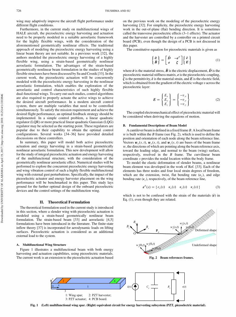
Figure 1 illustrates a multifunctional beam with both energyharvesting and actuation capabilities, using piezoelectric materials.The current work is an extension to the piezoelectric actuation based
on the previous work on the modeling of the piezoelectric energyharvesting [32]. For simplicity, the piezoelectric energy harvestingwork in the out-of-plane (flat) bending direction. It is sometimescalled the transverse piezoelectric effects (3–1 effects). The actuatorand the harvester are controlled by a controller on a printed circuitboard (PCB), even though the design of a PCB is not discussed inthis paper.The constitutive equation for piezoelectric materials is given as
��σ�B
��
��D −eTe ζ
���εE
�(1)
where �σ is the material stress, �B is the electric displacement, �D is thepiezoelectric material stiffnessmatrix, e is the piezoelectric coupling,ζ is the permittivity, �ε is the material strain, andE is the electric field,which is obtained from the gradient of the electric voltage v across thepiezoelectric layer:
E �8<:Ex
Ey
Ez
9=; �
8<:−v;x−v;y−v;z
9=; (2)
The coupled electromechanical effect of piezoelectricmaterial willbe considered when deriving the equations of motion.
B. Fundamental Descriptions of Beam Model
Acantilever beam is defined in a fixed frameB. A local beam framew is built within the B frame (see Fig. 2), which is used to define theposition and orientation of each node along the beam reference line.Vectors wx�s; t�, wy�s; t�, and wz�s; t� are bases of the beam framew, the directions of which are pointing along the beam reference axis,toward the leading edge, and normal to the beam (wing) surface,respectively, resolved in the B frame. The curvilinear beamcoordinate s provides the nodal location within the body frame.To model the elastic deformation of slender beams, a nonlinear
beam element was developed in the work of Ref. [33]. Each of theelements has three nodes and four local strain degrees of freedom,which are the extension, twist, flat bending rate (κy), and edgebending rate (κz), respectively, of the beam reference line,
εT�s� � f εx�s� κx�s� κy�s� κz�s� g (3)
which is not to be confused with the strain of the materials (�ε) inEq. (1), even though they are related.
Fig. 1 (Left) multifunctional wing spar. (Right) equivalent circuit for energy harvesting subsystem (PZT, piezoelectric material).
Fig. 2 Beam references frames.
726 TSUSHIMA AND SU
Dow
nloa
ded
by U
NIV
ER
SIT
Y O
F A
LA
BA
MA
on
Apr
il 19
, 201
7 | h
ttp://
arc.
aiaa
.org
| D
OI:
10.
2514
/1.C
0338
46
Positions and orientations of each node along the beam are
determined by a vector consisting of 12 components, which is
denoted as
hT�s� �npTw�s� wT
x �s� wTy �s� wT
z �s�oT
(4)
where pw is the nodal position resolved in the B frame and the
orientation is represented by the base vectors of thew frame (wx,wy,
and wz). The derivative and variation-dependent variable h are
derived from those of the independent variable ε using the Jacobians,given as
δh � Jhεδε dh � Jhεdε _h � Jhε _ε �h � Jhε �ε� _Jhε _ε (5)
where the Jacobians are obtained from kinematics [6,33],
Jhε �∂h∂ε
Jpε �∂pw
∂εJθε �
∂θ∂ε
(6)
with Jpε and Jθε being additional Jacobians relating the nodal
position and orientation to the elemental strain [6,33].
C. Equations of Motion
The equations of motion can be derived by following the principle
of virtual work extended to dynamic systems, which is equivalent to
Hamilton’s Principle. The detailed derivation, where the
electromechanical coupling effect was not considered, can be found
in previousworks of the Su andCesnik [4,33]. The electromechanical
coupling effect was further discussed and studied for energy
harvesting [32]. The internal virtual work will include contributions
of inertia forces, internal strains, strain rates, and the
electromechanical effects,
δW int � −δhTMs�h − δεTCs _ε − δεTKs�ε − ε0�
� δεT�Bva � Bvh�v� δv�BTvhε� Cpv�
(7)
where ε0 is the initial strain of the beam. Bva and Bvh are the
electromechanical coupling matrix for the piezoelectric actuator and
harvester, respectively. The couplingmatrixBvawill be derived in the
succeeding discussion, while Bvh is obtained from the cross-
sectional value,
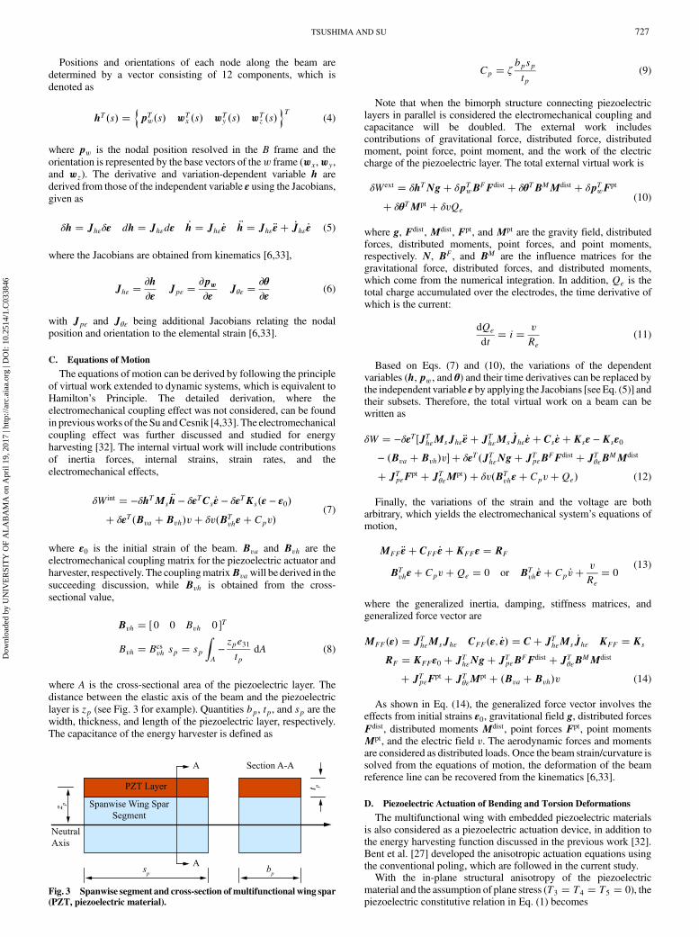
Bvh � � 0 0 Bvh 0 �T
Bvh � Bcsvh sp � sp
ZA−zpe31tp
dA (8)
where A is the cross-sectional area of the piezoelectric layer. The
distance between the elastic axis of the beam and the piezoelectric
layer is zp (see Fig. 3 for example). Quantities bp, tp, and sp are the
width, thickness, and length of the piezoelectric layer, respectively.
The capacitance of the energy harvester is defined as
Cp � ζbpsptp
(9)
Note that when the bimorph structure connecting piezoelectriclayers in parallel is considered the electromechanical coupling andcapacitance will be doubled. The external work includescontributions of gravitational force, distributed force, distributedmoment, point force, point moment, and the work of the electriccharge of the piezoelectric layer. The total external virtual work is
δWext � δhTNg� δpTwB
FFdist � δθTBMMdist � δpTwF
pt
� δθTMpt � δvQe
(10)
where g, Fdist, Mdist, Fpt, and Mpt are the gravity field, distributedforces, distributed moments, point forces, and point moments,respectively. N, BF, and BM are the influence matrices for thegravitational force, distributed forces, and distributed moments,which come from the numerical integration. In addition, Qe is thetotal charge accumulated over the electrodes, the time derivative ofwhich is the current:
dQe
dt� i � v
Re
(11)
Based on Eqs. (7) and (10), the variations of the dependentvariables (h, pw, and θ) and their time derivatives can be replaced bythe independent variable ε by applying the Jacobians [see Eq. (5)] andtheir subsets. Therefore, the total virtual work on a beam can bewritten as
δW � −δεT �JThεMsJhε �ε� JT
hεMs_Jhε _ε� Cs _ε� Ksε −Ksε0
− �Bva � Bvh�v� � δεT�JThεNg� JT
pεBFFdist � JT
θεBMMdist
� JTpεF
pt � JTθεM
pt� � δv�BTvhε� Cpv�Qe� (12)
Finally, the variations of the strain and the voltage are botharbitrary, which yields the electromechanical system’s equations ofmotion,
MFF �ε� CFF _ε� KFFε � RF
BTvhε� Cpv�Qe � 0 or BT
vh _ε� Cp _v�v
Re
� 0(13)
where the generalized inertia, damping, stiffness matrices, andgeneralized force vector are
MFF�ε� � JThεMsJhε CFF�ε; _ε� � C� JT
hεMs_Jhε KFF � Ks
RF � KFFε0 � JThεNg� JT
pεBFFdist � JT
θεBMMdist
� JTpεF
pt � JTθεM
pt � �Bva � Bvh�v (14)
As shown in Eq. (14), the generalized force vector involves theeffects from initial strains ε0, gravitational field g, distributed forcesFdist, distributed moments Mdist, point forces Fpt, point momentsMpt, and the electric field v. The aerodynamic forces and momentsare considered as distributed loads. Once the beam strain/curvature issolved from the equations of motion, the deformation of the beamreference line can be recovered from the kinematics [6,33].
D. Piezoelectric Actuation of Bending and Torsion Deformations
The multifunctional wing with embedded piezoelectric materialsis also considered as a piezoelectric actuation device, in addition tothe energy harvesting function discussed in the previous work [32].Bent et al. [27] developed the anisotropic actuation equations usingthe conventional poling, which are followed in the current study.With the in-plane structural anisotropy of the piezoelectric
material and the assumption of plane stress (T3 � T4 � T5 � 0), thepiezoelectric constitutive relation in Eq. (1) becomes
Fig. 3 Spanwise segment and cross-section ofmultifunctional wing spar(PZT, piezoelectric material).
TSUSHIMA AND SU 727
Dow
nloa
ded
by U
NIV
ER
SIT
Y O
F A
LA
BA
MA
on
Apr
il 19
, 201
7 | h
ttp://
arc.
aiaa
.org
| D
OI:
10.
2514
/1.C
0338
46

8>><>>:
�σ1�σ2�σ6�B3
9>>=>>;
�
2664
�D11�D12 0 −e31
�D12�D22 0 −e32
0 0 �D66 0
e31 e32 0 ζ33
37758>><>>:
�ε1�ε2�ε6�E3
9>>=>>;
(15)
in which (1, 2, 3) are the beam axes and ( ~1, ~2, ~3) are the piezoelectricmaterial axes (see Fig. 4).By applying the rotation of thematerial coordinate system from the
beam coordinate system by a�θ angle about the 3-axis, the matricesin the constitutive relation become
~�B � Te�B ~E � TeE ~�ε � Ts �ε ~�σ � �TT
s �−1 �σ (16)
and
��D −eTe ζ
�beam
��TTs~DTs −TT
s ~eTTe
TTe ~eTs TT
e~ζTe
�(17)
where the symbols with a tilde refer to the values in the piezoelectricmaterial axes. Ts and Te are the transformation matrices ofcomposites [38].For simplicity, the electric field and displacement are assumed to
be along the 3-direction. The reduced constitutive relation in thebeam system can be expressed as
��σ�B3
��
�TTs~DTs −Ts ~e
T
~eTTs
~ζ33
���εE3
�(18)
According to Eq. (17), the piezoelectric coupling in the beamsystem is obtained as
e � TTe ~eTs
e31 � ~e31cos2θ� ~e32sin
2θ
e32 � ~e31sin2θ� ~e32cos
2θ
e36 � cos θ sin θ� ~e31 − ~e32� (19)
where e36 is the piezoelectric coupling for the induced shear stress.The piezoelectric induced stress can be obtained from Eq. (18) as
�σpe � −TTs ~e
TE3 (20)
The resultant force and moment can be calculated from thepiezoelectric induced terms. Bent et al. [27] developed the force andmoment in thin-walled anisotropic composite structures using theClassical Laminated Plate Theory [38]. On the other hand, if thecomposite structure is a simple rectangular thin-walled section, onemay choose an approach using the piezoelectric induced stresses tocalculate the induced bending and torsional moments as in Ref. [28].The coupling matrix Bva relates the actuation voltage and the
resultant piezoelectric force and moment, given as
8>><>>:
Bva1
Bva2
Bva3
Bva4
9>>=>>;v �
8>><>>:
F1a
M1a
M2a
M3a
9>>=>>;
(21)
whereF1a is a piezoelectric induced extensional force, andM1a,M2a,andM3a are piezoelectric inducedmoments about the 1, 2, and 3 axes,respectively. In this paper, the 1, 2, and 3 axes are oriented so that thecoordinate is aligned with the wing beam coordinate axes x, y and z.
E. Unsteady Aerodynamics
The distributed loads Fdist and Mdist in Eq. (14) are divided intoaerodynamic loads and user-supplied loads. The unsteadyaerodynamic loads used in the current study are based on the two-dimensional (2D) finite-state inflow theory, provided by Peters andJohnson [37]. The theory calculates aerodynamic loads on a thinairfoil section undergoing large motions in an incompressibleinviscid subsonic flow. The lift, moment, and drag of a thin 2D airfoilsection about its midchord are given by
lmc � πρb2�−�z� _y _α−d �α� � 2πρb _y2�−_z
_y�
�1
2b − d
�_α
_y−λ0_y
�
mmc � 2πρb2�−1
2_y _z−
1
2d _y _α−
1
2_yλ0 −
1
16b2 �α
�
dmc � −2πρb�_z2 � d2 _α2 � λ20 � 2d_α _z�2d _αλ0� (22)
whereb is the semichord andd is the distance of themidchord in frontof the reference axis. The quantity − _z∕ _y is the angle of attack thatconsists of the contribution from both the steady-state angle of attackand the unsteady plunging motion of the airfoil. The differentvelocity components are shown in Fig. 5. The inflow velocity λ0accounts for induced flow due to free vorticity, which is theweightedsummation of the inflow states λ as described by Peters and Johnson[37] and governed by
_λ � F1 �ε� F2 _ε� F3λ (23)
The aerodynamic loads about the midchord center are transferredto the wing elastic axis and rotated into the fixed B frame for thesolution of equations of motion.
F. Feedback Control Algorithms
A LQR [34] (see Fig. 6) is commonly used in traditional aircraftcontrol studies. To apply the linear control theory, the linearization ofthe nonlinear aeroelastic equations about a nonlinear equilibriumstate is performed. The nonlinear aeroelastic equations of thecantilever wing are repeated here, without considering the gravity,
Fig. 4 Composite material axis and beam axis systems.
Fig. 5 Airfoil coordinate system and velocity components.
Fig. 6 LQR feedback control diagram.
728 TSUSHIMA AND SU
Dow
nloa
ded
by U
NIV
ER
SIT
Y O
F A
LA
BA
MA
on
Apr
il 19
, 201
7 | h
ttp://
arc.
aiaa
.org
| D
OI:
10.
2514
/1.C
0338
46

MFF �ε� CFF _ε� KFFε � RaeroF � Bvv _λ � F1 �ε� F2 _ε� F3λ
(24)
and
RaeroF � JT
pεBFFaero � JT
θεBMMaero (25)
whereRaeroF is the generalized aerodynamic load.Faero andMaero are
the distributed aerodynamic lift and moment, respectively. Bv is thepiezoelectric matrix, and v is electric voltage. The referencenonlinear equilibrium state where the linearization is performed is
x0 �n�εT0 ; _ε
T0 ; ε
T0 ; λ
T0
oT
(26)
The structural Jacobians are assumed to be constant when thesystem is perturbed for the linearization, while this assumption holdsfor small perturbations to the system. This assumption helps tosimplify the linearization process by making the generalized massmatrices independent of the state variables. Each equation is writtenwith the small perturbation about the nonlinear equilibrium state,which yields
�MFF �ε� �CFF _ε� �KFFε −RaeroF∕λ0λ −Bvv � 0
_λ − F1 �ε − F2 _ε − F3λ � 0(27)
where �M, �C, and �K are the linearized general inertia, damping, andstiffness matrices, respectively. Raero
F∕λ0 is the derivative of theaerodynamic load vector with respect to the inflow states.Equation (27) can be put into the state-space form
_x � Ax� Bu (28)
where
x �nεT _εT λT
oT
u � v (29)
where v is the input of piezoelectric actuation.The associated quadratic performance index for control is defined as
J �Z
∞
0
�xTQx� uTRu
dt (30)
where R andQ are positive-definite penalty matrices. The controlgainK is determined byminimizing the cost function J in Eq. (30),and the control input u (or the piezoelectric actuation voltage v) isdetermined by
u � −Kx (31)
The LQR results in a robust closed-loop control system.However, the LQR design assumes all the states of the system areavailable for the feedback, which is not always true for mostpractical cases. The LQG regulator provides the compensation tothe limitation of state variable availability. It also takes intoaccount the process and measurement noises of the system. TheLQG regulator consists of an LQR and a Kalman filter for the stateestimation (see Fig. 7). The state-space model describing theproblem is now given as
_x � Ax� Bu� Gw y � Cx�Du�Hw� n (32)
where x is the state vector, u is the control input to the system plant,y is a user-defined system output vector (wing spanwise bendingand torsion curvatures in the current study), and w is thedisturbance (process noise). Here, local strains are assumed to bemeasured by a certain sensor (e.g., strain gauges or piezoelectricsensors), withn being the possible sensor measurement noise. Thenoises w and n are zero-mean white noises. The Kalman filterprovides an estimated x̂ to the state x, such that the control input isobtained as
u � −Kx̂ (33)
G. Weighted Control Penalty
The linear quadratic controllers minimize a certain performanceindex by applying penalties on both the states and control inputs.Different combinations of penalties may result in different controlsystem performances. Therefore, it is important to establish anapproach to evaluate the tradeoff and find a cost-effective controllersetting.
Fig. 7 LQG regulator feedback control diagram.
Fig. 8 State and control cost curve for finding the cost-effective point.
Table 2 Material properties for the wing layers
Property E-Glass AFC
E1, GPa 19.3 42.2E2, GPa 19.3 17.5E3, GPa 9.8 17.5G12, GPa 4.1 5.5G13, GPa 4.1 5.5G23, GPa 3.28 4.4v12 0.148 0.354v13 0.148 0.354v23 0.207 0.496Thickness, mm 0.1143 0.127d11, pm∕V — — 309d12, pm∕V — — −129Electrode distance, mm — — 1.143
Table 1 Wing properties
Airfoil NACA0014
Span, cm 200Chord length (at root), cm 20Taper ratio 1∶2Reference axis location (from leading edge) 30% of chordCenter of gravity (from leading edge) 30% of chord
TSUSHIMA AND SU 729
Dow
nloa
ded
by U
NIV
ER
SIT
Y O
F A
LA
BA
MA
on
Apr
il 19
, 201
7 | h
ttp://
arc.
aiaa
.org
| D
OI:
10.
2514
/1.C
0338
46

A good approach to evaluate the performance is to normalize the
cost function and to split them into two components of state
variables and control inputs, respectively, which can be defined as
the state cost Js and the control cost Jc [39]. The objective cost
function defined in Eq. (30) can be rewritten with an additional
weighting term r:
J �Z
∞
0
�xTQx� ruTRu�dt (34)
This cost function has two contributors as
Js �Z
∞
0
�xTQx�dt Jc �Z
∞
0
�uTRu�dt (35)
To have the kinetic and strain energy form of the system in the
state cost, Q can be defined as
Q ��Ks 00 Ms
�(36)
The control cost is the integral of actuation energy with respect to
time. In the design process, Js and Jc are obtained by solving
Lyapunov and Riccati equations [39]. Theweighting r in Eq. (34) isto control the penalty balance between state cost and control cost.
Using this weighting value, the state and control costs can be
normalized as
JS � Js JC � Jcr
(37)
As a preliminary design, the approach used in Ref. [39] is applied
here to determine a balanced control setting between the state and
control costs. Figure 8 exemplifies the normalized cost functions to
determine a feasible preliminary design point. The balanced penalty
Fig. 9 Wing dimensions.
Fig. 11 Extensional strain and twist curvature of the active wing with static voltage actuation.
Fig. 12 Out-of-plane and edge bending curvatures of the active wing with static voltage actuation.
Fig. 10 Layups of the wing cross-section (AFC, active fiber composite).
730 TSUSHIMA AND SU
Dow
nloa
ded
by U
NIV
ER
SIT
Y O
F A
LA
BA
MA
on
Apr
il 19
, 201
7 | h
ttp://
arc.
aiaa
.org
| D
OI:
10.
2514
/1.C
0338
46

point, or cost effective point, can be found at the vertex of thehyperbolic curve.
III. Numerical Verification of Anisotropic PiezoelectricActuation
In this section, the anisotropic actuationmodel implemented in thestrain-based beam formulation is validated, while other aspects of thecomplete formulation, such as the aeroelastic formation [4,5] andpiezoelectric energy harvesting [32], have been validated or verifiedin previous studies. For this purpose, the composite wing studied inRef. [39] is modeled here. While the detailed wing properties can be
found inRef. [39], Tables 1 and 2 list the basic geometric andmaterial
properties of thewing. Figure 9 shows thewing geometry, and Fig. 10
highlights the layups of thewing cross-section. A single passivewing
spar is built at 40% chord from the leading edge within the wing
cross-section.
Although the studies in Ref. [39] covered different actuator
orientations from 0 to �45 deg, only the actuation oriented at
�22 deg is performed in the current study to have the balanced
bending and torsional actuation capability.
Figures 11 and 12 compare the extensional strain, twist, out-of-
plane, and edge bending curvatures from the current simulation and
those from Ref. [39] with a 2000 V static actuation voltage. After a
convergence study, the wing is divided into ten strain-based beam
elements in the current simulation, with three elements in the uniform
segment and seven in the tapered segment. Gravity and aerodynamic
loads are not included as Ref. [39]. Overall, there is an excellent
agreement between the two sets of results.
IV. Numerical Studies
Nonlinear active aeroelastic analysis results are presented here for
the slender wing studied in the previous section, which are obtained
by using the derived electroaeroelastic formulation. Feedback
controls of wing vibrations due to gust disturbances are also
discussed. Particularly, concurrent active piezoelectric actuation and
energy harvesting are explored with the wing model. In doing so, a
parametric study of the impact of the piezoelectric actuator and
energy harvester placement on the wing performance will be
presented, where both the effectiveness of gust alleviation and the
voltage output from the multifunctional wing will be simultaneously
explored.
Fig. 13 Gust velocity profiles and PSD function.
Fig. 14 Partition of the multifunctional wing.
Fig. 15 Wing tip deflection with gust profile 1.
Table 4 List of different multifunctional wingconfigurations
Configuration
Function 1 2 3 4
Actuator element ID 1–10 1–5 1–3 1Harvester element ID — — 6–10 7–10 2–10
Table 3 RMS bending and twist curvatures on each wing element with gust perturbation
Element
State variable 1 2 3 4 5 6 7 8 9 10
Flat bending curvature (m−1) 0.1250 0.0977 0.0742 0.0668 0.0583 0.0486 0.0376 0.0253 0.0127 0.0028Twist curvature (×10−4 m−1) 20.105 14.653 10.920 10.008 9.2634 8.5939 7.8640 6.8714 5.2754 2.3794
TSUSHIMA AND SU 731
Dow
nloa
ded
by U
NIV
ER
SIT
Y O
F A
LA
BA
MA
on
Apr
il 19
, 201
7 | h
ttp://
arc.
aiaa
.org
| D
OI:
10.
2514
/1.C
0338
46

A. Gust Model and Wing Actuator and Energy Harvester Design
To evaluate the wing behavior under stochastic gust perturbations,
two different gust signals are generated based on the power spectral
density (PSD) function of the Dryden gust model with the gust
strength of 30 m∕s, the velocity profiles of which are plotted in
Fig. 13. The freesteam velocity is 70 m∕s, and the altitude is
15,000 m. This flight condition is used in all the following studies.
Note a detailed description of implementing the Dryden gust model
was provided in Ref. [32].
The wing model studied in the previous section is used here to
design the multifunctional wing. The wing is still divided into ten
elements, all with the embedded piezoelectric material. They can
all be flexibly designated as either active actuators for the vibration
control or harvesters for the energy conversion. Figure 14
describes the conceptual multifunctional wing design. To
determine the effective actuator and energy harvester placement,
thewing vibration with the gust perturbation is first simulated with
no piezoelectric effects. A time step of 0.01 s is used in all time-
domain simulations with a cantilever boundary condition.
Figure 15 shows the uncontrolled wing tip vertical deflection over
10 s with gust profile 1 (see Fig. 13) and an 8 deg angle of attack.
Table 3 lists the rms bending and twist curvatures of each wing
element during the 10 s simulation. According to the wing
deformation, the wing portion closer to the root exhibits larger
bending and twist curvatures, compared to the tip portion.
Therefore, it is more efficient to put the controllers closer to the
wing root for a better vibration control. The rest of the wing
elements can then be used as energy harvesters. Alternatively, one
may want to use an opposite configuration to maximize the output
voltage from energy harvesters if thewing vibration is allowed and
more energy output is desired. In this paper, the priority is given to
the wing vibration control. For parametric study purposes, four
different wing configurations are considered in the current studylisted in Table 4, where element identifiers (IDs) are assigned from thewing root to the tip, ranging from 1 to 10. Lastly, the piezoelectricresistance load of the energy harvesting circuit is set to be 1 MΩ.
B. Gust Suppression Using LQR
The wing active control study starts by using the wingconfiguration with full-span actuators (configuration 1). To evaluatethe controllers’ effectiveness with different gust perturbations, bothgust profiles 1 and 2 are applied. The wing tip vertical deflectionswith the designed LQR controller under gust profiles 1 and 2,respectively, are shown in Fig. 16. As is done in traditional gustcontrol studies, one may design a controller to suppress the gustvibration as much as possible. In this case, the weighting parameter rfor the LQR controller is 5.00 × 10⁻¹⁰, resulting in an effective gustsuppression. Table 5 gives the list of the original state and controlcosts of the simulations [calculated by using Eq. (35)]. The state costreduction with respect to the uncontrolled vibration is used tomeasure the performance of thevibration control since it is essentiallya summation of thewing vibrational kinetic energy and strain energy.One can find a 98.90% and a 98.96% state cost reduction,respectively, by applying the LQR controller under the two gusts.However, this suppression is achieved at the cost of a significantamount of control effort. This can be observed from Table 6, whichlists the rms voltage inputs for each actuator during the simulation.
C. Integral Multifunctional Wing for Concurrent Active Control andEnergy Harvesting
As discussed before, for concurrent active actuation and energyharvesting of the multifunctional wing, one does not need to push tothe limit to minimize the wing vibration. If a certain magnitude ofwing vibration is allowed and it does not significantly impact wing
Fig. 16 Wing tip deflections with LQR controller under gust profiles 1 (left) and 2 (right) for wing configuration 1.
Table 5 State and control costs on wing configuration 1 under both gust profiles
Gust profile Cost, J ⋅ s No control LQR controller State cost reduction, %
1 State cost 29.78 0.33 98.90Control cost, ×108 — — 5.96 — —
2 State cost 17.04 0.18 98.96Control cost, ×108 — — 3.22 — —
Table 6 RMS voltage input (Vrms, V) along wing configuration 1
Element ID
Gust profile 1 2 3 4 5 6 7 8 9 10
1 4913.1 3810.1 2868.6 2373.0 1894.6 1433.1 994.1 593.3 261.2 50.42 3603.5 2796.9 2108.4 1746.7 1396.9 1058.5 735.6 440.0 194.1 37.6
732 TSUSHIMA AND SU
Dow
nloa
ded
by U
NIV
ER
SIT
Y O
F A
LA
BA
MA
on
Apr
il 19
, 201
7 | h
ttp://
arc.
aiaa
.org
| D
OI:
10.
2514
/1.C
0338
46
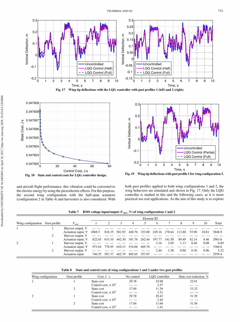
and aircraft flight performance, this vibration could be converted to
the electric energy by using the piezoelectric effects. For this purpose,
the second wing configuration with the half-span actuators
(configuration 2 in Table 4) and harvesters is also considered. With
both gust profiles applied to both wing configurations 1 and 2, the
wing behaviors are simulated and shown in Fig. 17. Only the LQG
controller is studied in this and the following cases, as it is more
practical use real applications. As the aim of this study is to explore
0 20 40 60 800.347922
0.347923
0.347924
0.347925
0.347926
0.347927
0.347928
0.347929
Control Cost, J·s
Sta
te C
ost,
J·s
Fig. 18 State and control costs for LQG controller design.
Table 7 RMS voltage input/output (Vrms, V) of wing configurations 1 and 2
Element ID
Wing configuration Gust profile Vrms 1 2 3 4 5 6 7 8 9 10 Total
1 1 Harvest output, V — — — — — — — — — — — — — — — — — — — — — —
Actuation input, V 1068.5 818.35 581.93 440.76 333.08 249.16 178.64 113.80 53.90 10.81 3848.92 Harvest output, V — — — — — — — — — — — — — — — — — — — — — —
Actuation input, V 822.65 615.10 442.30 341.76 262.44 197.77 141.50 89.49 42.14 8.46 2963.62 1 Harvest output, V — — — — — — — — — — 3.16 2.05 1.13 0.46 0.08 6.89
Actuation input, V 973.64 778.95 610.13 534.06 469.78 — — — — — — — — — — 3366.62 Harvest output, V — — — — — — — — — — 2.44 1.58 0.88 0.36 0.06 5.32
Actuation input 746.55 587.37 462.79 405.65 357.07 — — — — — — — — — — 2559.4
Table 8 State and control costs of wing configurations 1 and 2 under two gust profiles
Wing configuration Gust profile Cost, J ⋅ s No control LQG controller State cost reduction, %
1 1 State cost 29.78 19.98 32.91Control cost, × 107 — — 2.57 — —
2 State cost 17.04 11.36 33.32Control cost, × 107 — — 1.51 — —
2 1 State cost 29.78 20.43 31.39Control cost, × 107 — — 2.44 — —
2 State cost 17.04 11.66 31.56Control cost, × 107 — — 1.41 — —
Fig. 17 Wing tip deflections with the LQG controller with gust profiles 1 (left) and 2 (right).
Fig. 19 Wing tip deflectionswith gust profile 1 forwing configuration 3.
TSUSHIMA AND SU 733
Dow
nloa
ded
by U
NIV
ER
SIT
Y O
F A
LA
BA
MA
on
Apr
il 19
, 201
7 | h
ttp://
arc.
aiaa
.org
| D
OI:
10.
2514
/1.C
0338
46
the dual functions of the multifunctional wing, the controllers are
designed to have a balanced control performance with the weight
parameter r being 8.86 × 10⁻⁸ (around the vertex of the cost curve inFig. 18). Table 7 lists the rms voltage inputs/outputs on each element,
while the simple summation of the rms voltage outputs is called the
total output. Note a more accurate estimation of the total voltage
output depends on the system’s circuit, which is not discussed herein.
Over the 10 s simulation, wing configuration 2 accumulates a total
voltage output of 6.89 and 5.32 V with the two applied profiles,respectively. Additionally, the required actuation voltage input alsodrops from configuration 1 to configuration 2. Therefore, using thesecondwing configuration saves energy. One can further evaluate thevibration reduction performance of the two configurations bycomparing the states and control costs, which are listed in Table 8.Obviously, the state cost reductions of the two configurations areveryclose. Therefore, wing configuration 2 with the corresponding LQGcontroller has almost the same vibration control performance, at alower voltage input with some additional energy savings. Thisconfiguration takes advantage of the dual functions of themultifunctional wing.In the next study, the number ofwing actuators is further reduced to
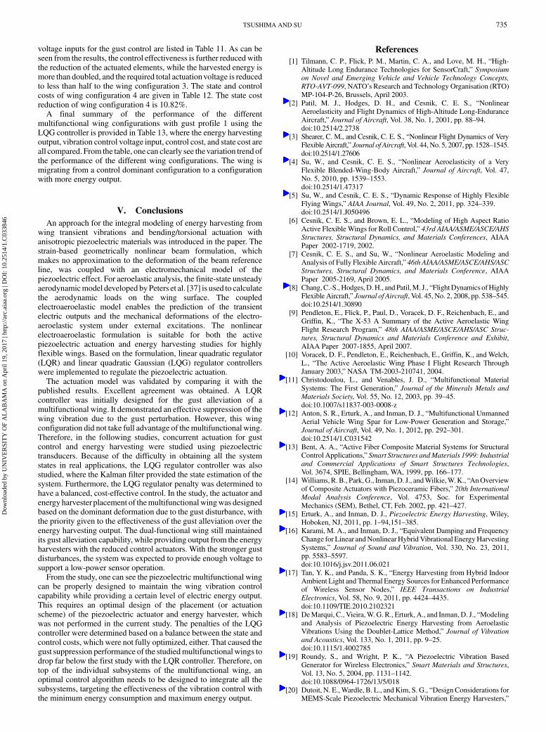
3 (see Table 4 for wing configuration 3), while the energy harvestersoccupy from 30% to the full span of the wing. Since the two gustprofiles do not introduce qualitatively different wing behaviors, onlygust profile 1 is used from now on. The wing tip deflection with thegust perturbation is plotted in Fig. 19, which is also compared withthose of the uncontrolled wing and the onewith full-span actuators. Itcan be seen that, even if the number of actuators is reduced from 10 to3, the controller still maintains the gust alleviation capability. Theoutput/input voltage from each harvester/actuator and the totalvoltage over the 10 s are listed in Table 9. The total output voltagefrom the harvesters is 17.24 V, which might be available for somelow-power sensors’ operation. However, the required controlactuation voltage is still much higher than the harvester output. Thus,an additional power supply would be required for the actuation. Thestate and control costs with the LQG controller are listed in Table 10.The state cost reduction of the wing with partial-span actuatorsis 24.83%.Finally,wing configuration 4 is applied in the study,where only the
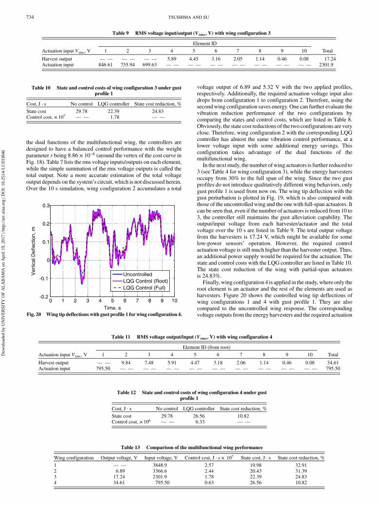
root element is an actuator and the rest of the elements are used asharvesters. Figure 20 shows the controlled wing tip deflections ofwing configurations 1 and 4 with gust profile 1. They are alsocompared to the uncontrolled wing response. The correspondingvoltage outputs from the energy harvesters and the required actuation
Table 9 RMS voltage input/output (Vrms, V) with wing configuration 3
Element ID
Actuation input Vrms, V 1 2 3 4 5 6 7 8 9 10 Total
Harvest output — — — — — — 5.89 4.45 3.16 2.05 1.14 0.46 0.08 17.24Actuation input 846.61 755.94 699.63 — — — — — — — — — — — — — — 2301.9
Table 10 State and control costs of wing configuration 3 under gustprofile 1
Cost, J ⋅ s No control LQG controller State cost reduction, %
State cost 29.78 22.39 24.83Control cost, × 107 — — 1.78 — —
Table 13 Comparison of the multifunctional wing performance
Wing configuration Output voltage, V Input voltage, V Control cost, J ⋅ s × 107 State cost, J ⋅ s State cost reduction, %
1 — — 3848.9 2.57 19.98 32.912 6.89 3366.6 2.44 20.43 31.393 17.24 2301.9 1.78 22.39 24.834 34.61 795.50 0.63 26.56 10.82
Table 12 State and control costs of wing configuration 4 under gustprofile 1
Cost, J ⋅ s No control LQG controller State cost reduction, %
State cost 29.78 26.56 10.82Control cost, × 106 — — 6.33 — —
Table 11 RMS voltage output/input (Vrms, V) with wing configuration 4
Element ID (from root)
Actuation input Vrms, V 1 2 3 4 5 6 7 8 9 10 Total
Harvest output — — 9.84 7.48 5.91 4.47 3.18 2.06 1.14 0.46 0.08 34.61Actuation input 795.50 — — — — — — — — — — — — — — — — — — 795.50
Fig. 20 Wing tip deflectionswith gust profile 1 forwing configuration 4.
734 TSUSHIMA AND SU
Dow
nloa
ded
by U
NIV
ER
SIT
Y O
F A
LA
BA
MA
on
Apr
il 19
, 201
7 | h
ttp://
arc.
aiaa
.org
| D
OI:
10.
2514
/1.C
0338
46
voltage inputs for the gust control are listed in Table 11. As can beseen from the results, the control effectiveness is further reducedwiththe reduction of the actuated elements, while the harvested energy ismore than doubled, and the required total actuationvoltage is reducedto less than half to the wing configuration 3. The state and controlcosts of wing configuration 4 are given in Table 12. The state costreduction of wing configuration 4 is 10.82%.A final summary of the performance of the different
multifunctional wing configurations with gust profile 1 using theLQG controller is provided in Table 13, where the energy harvestingoutput, vibration control voltage input, control cost, and state cost areall compared. From the table, one can clearly see thevariation trend ofthe performance of the different wing configurations. The wing ismigrating from a control dominant configuration to a configurationwith more energy output.
V. Conclusions
An approach for the integral modeling of energy harvesting fromwing transient vibrations and bending/torsional actuation withanisotropic piezoelectric materials was introduced in the paper. Thestrain-based geometrically nonlinear beam formulation, whichmakes no approximation to the deformation of the beam referenceline, was coupled with an electromechanical model of thepiezoelectric effect. For aeroelastic analysis, the finite-state unsteadyaerodynamicmodel developed byPeters et al. [37] is used to calculatethe aerodynamic loads on the wing surface. The coupledelectroaeroelastic model enables the prediction of the transientelectric outputs and the mechanical deformations of the electro-aeroelastic system under external excitations. The nonlinearelectroaeroelastic formulation is suitable for both the activepiezoelectric actuation and energy harvesting studies for highlyflexible wings. Based on the formulation, linear quadratic regulator(LQR) and linear quadratic Gaussian (LQG) regulator controllerswere implemented to regulate the piezoelectric actuation.The actuation model was validated by comparing it with the
published results. Excellent agreement was obtained. A LQRcontroller was initially designed for the gust alleviation of amultifunctional wing. It demonstrated an effective suppression of thewing vibration due to the gust perturbation. However, this wingconfiguration did not take full advantage of themultifunctional wing.Therefore, in the following studies, concurrent actuation for gustcontrol and energy harvesting were studied using piezoelectrictransducers. Because of the difficulty in obtaining all the systemstates in real applications, the LQG regulator controller was alsostudied, where the Kalman filter provided the state estimation of thesystem. Furthermore, the LQG regulator penalty was determined tohave a balanced, cost-effective control. In the study, the actuator andenergy harvester placement of themultifunctionalwingwas designedbased on the dominant deformation due to the gust disturbance, withthe priority given to the effectiveness of the gust alleviation over theenergy harvesting output. The dual-functional wing still maintainedits gust alleviation capability, while providing output from the energyharvesters with the reduced control actuators. With the stronger gustdisturbances, the system was expected to provide enough voltage tosupport a low-power sensor operation.From the study, one can see the piezoelectric multifunctional wing
can be properly designed to maintain the wing vibration controlcapability while providing a certain level of electric energy output.This requires an optimal design of the placement (or actuationscheme) of the piezoelectric actuator and energy harvester, whichwas not performed in the current study. The penalties of the LQGcontroller were determined based on a balance between the state andcontrol costs, which were not fully optimized, either. That caused thegust suppression performance of the studiedmultifunctional wings todrop far below the first study with the LQR controller. Therefore, ontop of the individual subsystems of the multifunctional wing, anoptimal control algorithm needs to be designed to integrate all thesubsystems, targeting the effectiveness of the vibration control withthe minimum energy consumption and maximum energy output.
References
[1] Tilmann, C. P., Flick, P. M., Martin, C. A., and Love, M. H., “High-Altitude Long Endurance Technologies for SensorCraft,” Symposium
on Novel and Emerging Vehicle and Vehicle Technology Concepts,
RTO-AVT-099, NATO’s Research and Technology Organisation (RTO)MP-104-P-26, Brussels, April 2003.
[2] Patil, M. J., Hodges, D. H., and Cesnik, C. E. S., “NonlinearAeroelasticity and Flight Dynamics of High-Altitude Long-EnduranceAircraft,” Journal of Aircraft, Vol. 38, No. 1, 2001, pp. 88–94.doi:10.2514/2.2738
[3] Shearer, C. M., and Cesnik, C. E. S., “Nonlinear Flight Dynamics of VeryFlexibleAircraft,” Journal of Aircraft, Vol. 44, No. 5, 2007, pp. 1528–1545.doi:10.2514/1.27606
[4] Su, W., and Cesnik, C. E. S., “Nonlinear Aeroelasticity of a VeryFlexible Blended-Wing-Body Aircraft,” Journal of Aircraft, Vol. 47,No. 5, 2010, pp. 1539–1553.doi:10.2514/1.47317
[5] Su, W., and Cesnik, C. E. S., “Dynamic Response of Highly FlexibleFlying Wings,” AIAA Journal, Vol. 49, No. 2, 2011, pp. 324–339.doi:10.2514/1.J050496
[6] Cesnik, C. E. S., and Brown, E. L., “Modeling of High Aspect RatioActive Flexible Wings for Roll Control,” 43rd AIAA/ASME/ASCE/AHS
Structures, Structural Dynamics, and Materials Conferences, AIAAPaper 2002-1719, 2002.
[7] Cesnik, C. E. S., and Su, W., “Nonlinear Aeroelastic Modeling andAnalysis of Fully Flexible Aircraft,” 46th AIAA/ASME/ASCE/AHS/ASC
Structures, Structural Dynamics, and Materials Conference, AIAAPaper 2005-2169, April 2005.
[8] Chang,C.-S., Hodges,D.H., and Patil,M. J., “FlightDynamics ofHighlyFlexible Aircraft,” Journal of Aircraft, Vol. 45, No. 2, 2008, pp. 538–545.doi:10.2514/1.30890
[9] Pendleton, E., Flick, P., Paul, D., Voracek, D. F., Reichenbach, E., andGriffin, K., “The X-53 A Summary of the Active Aeroelastic WingFlight Research Program,” 48th AIAA/ASME/ASCE/AHS/ASC Struc-
tures, Structural Dynamics and Materials Conference and Exhibit,AIAA Paper 2007-1855, April 2007.
[10] Voracek, D. F., Pendleton, E., Reichenbach, E., Griffin, K., and Welch,L., “The Active Aeroelastic Wing Phase I Flight Research ThroughJanuary 2003,” NASA TM-2003-210741, 2004.
[11] Christodoulou, L., and Venables, J. D., “Multifunctional MaterialSystems: The First Generation,” Journal of the Minerals Metals and
Materials Society, Vol. 55, No. 12, 2003, pp. 39–45.doi:10.1007/s11837-003-0008-z
[12] Anton, S. R., Erturk, A., and Inman, D. J., “Multifunctional UnmannedAerial Vehicle Wing Spar for Low-Power Generation and Storage,”Journal of Aircraft, Vol. 49, No. 1, 2012, pp. 292–301.doi:10.2514/1.C031542
[13] Bent, A. A., “Active Fiber Composite Material Systems for StructuralControl Applications,” Smart Structures andMaterials 1999: Industrial
and Commercial Applications of Smart Structures Technologies,Vol. 3674, SPIE, Bellingham, WA, 1999, pp. 166–177.
[14] Williams,R.B., Park,G., Inman,D. J., andWilkie,W.K., “AnOverviewof Composite Actuators with Piezoceramic Fibers,” 20th International
Modal Analysis Conference, Vol. 4753, Soc. for ExperimentalMechanics (SEM), Bethel, CT, Feb. 2002, pp. 421–427.
[15] Erturk, A., and Inman, D. J., Piezoelectric Energy Harvesting, Wiley,Hoboken, NJ, 2011, pp. 1–94,151–385.
[16] Karami, M. A., and Inman, D. J., “Equivalent Damping and FrequencyChange for Linear andNonlinearHybridVibrational EnergyHarvestingSystems,” Journal of Sound and Vibration, Vol. 330, No. 23, 2011,pp. 5583–5597.doi:10.1016/j.jsv.2011.06.021
[17] Tan, Y. K., and Panda, S. K., “Energy Harvesting from Hybrid IndoorAmbient Light and Thermal Energy Sources for Enhanced Performanceof Wireless Sensor Nodes,” IEEE Transactions on Industrial
Electronics, Vol. 58, No. 9, 2011, pp. 4424–4435.doi:10.1109/TIE.2010.2102321
[18] DeMarqui, C., Vieira,W.G. R., Erturk, A., and Inman, D. J., “Modelingand Analysis of Piezoelectric Energy Harvesting from AeroelasticVibrations Using the Doublet-Lattice Method,” Journal of Vibration
and Acoustics, Vol. 133, No. 1, 2011, pp. 9–25.doi:10.1115/1.4002785
[19] Roundy, S., and Wright, P. K., “A Piezoelectric Vibration BasedGenerator for Wireless Electronics,” Smart Materials and Structures,Vol. 13, No. 5, 2004, pp. 1131–1142.doi:10.1088/0964-1726/13/5/018
[20] Dutoit, N. E.,Wardle, B. L., andKim, S. G., “Design Considerations forMEMS-Scale Piezoelectric Mechanical Vibration Energy Harvesters,”
TSUSHIMA AND SU 735
Dow
nloa
ded
by U
NIV
ER
SIT
Y O
F A
LA
BA
MA
on
Apr
il 19
, 201
7 | h
ttp://
arc.
aiaa
.org
| D
OI:
10.
2514
/1.C
0338
46
Integrated Ferroelectrics, Vol. 71, No. 1, 2005, pp. 121–160.doi:10.1080/10584580590964574
[21] Bilgen,O.,Wang,Y., and Inman,D. J., “Electromechanical Comparisonof Cantilevered Beams with Multifunctional Piezoceramic Devices,”Mechanical Systems and Signal Processing, Vol. 27, No. 1, 2012,pp. 763–777.doi:10.1016/j.ymssp.2011.09.002
[22] Wang, Y., and Inman, D. J., “Simultaneous Energy Harvesting and GustAlleviation for a Multifunctional CompositeWing Spar Using ReducedEnergy Control via Piezoceramics,” Journal of Composite Materials,Vol. 47, No. 1, 2013, pp. 125–146.doi:10.1177/0021998312448677
[23] Sodano, H. A., Park, G., and Inman, D. J., “Estimation of ElectricCharge Output for Piezoelectric Energy Harvesting,” Strain, Vol. 40,No. 2, 2004, pp. 49–58.doi:10.1111/str.2004.40.issue-2
[24] Hagood, N. W., Chung, W. H., and von Flotow, A., “Modelling ofPiezoelectric Actuator Dynamics for Active Structural Control,”Journal of Intelligent Material Systems and Structures, Vol. 1, No. 3,1990, pp. 327–354.doi:10.1177/1045389X9000100305
[25] Crawley, E. F., and Anderson, E. H., “Detailed Models of PiezoceramicActuation of Beams,” Journal of Intelligent Material Systems and
Structures, Vol. 1, No. 1, 1990, pp. 4–25.doi:10.1177/1045389X9000100102
[26] Erturk, A., and Inman, D. J., “Issues in Mathematical Modeling ofPiezoelectric Energy Harvesters,” Smart Materials and Structures,Vol. 17, No. 6, 2008, pp. 1–14.doi:10.1088/0964-1726/17/6/065016
[27] Bent, A. A., Hagood, N. W., and Rodgers, J. P., “Anisotropic Actuationwith Piezoelectric Fiber Composites,” Journal of Intelligent Material
Systems and Structures, Vol. 6, No. 3, 1995, pp. 338–349.doi:10.1177/1045389X9500600305
[28] Wilkie, W. K., Belvin, W. K., and Park, K. C., “Aeroelastic Analysisof Helicopter Rotor Blades Incorporating anisotropic PiezoelectricTwist Actuation,” ASME 1996 World Congress and Exposition,
Vol. 52, American Soc. of Mechanical Engineers, New York, 1996,pp. 423–434.
[29] Cesnik, C. E. S., and Ortega-Morales, M., “Active Beam Cross-Sectional Modeling,” Journal of Intelligent Material Systems and
Structures, Vol. 12, No. 7, 2001, pp. 483–496.doi:10.1177/10453890122145285
[30] Cesnik, C. E. S., and Shin, S., “Structural Analysis for Designing RotorBlades with Integral Actuators,” 39th Structures, Structural Dynamics,and Materials Conference, AIAA Paper 1998-2107, April 1998.
[31] Du Plessis, A. J., “Modeling and Experimental Testing of TwistActuated Single Cell Composite Beams for Helicopter Blade Control,”M.S.Thesis,Massachusetts Inst. of Technology, Cambridge,MA, 1996.
[32] Tsushima, N., and Su, W., “Modeling of Highly FlexibleMultifunctional Wings for Energy Harvesting,” Journal of Aircraft,Vol. 53, No. 4, Feb. 2016, pp. 1033–1044.doi:10.2514/1.C033496
[33] Su,W., andCesnik, C. E. S., “Strain-BasedGeometricallyNonlinearBeamFormulation forModelingVery FlexibleAircraft,” International Journal ofSolids and Structures, Vol. 48, Nos. 16–17, 2011, pp. 2349–2360.doi:10.1016/j.ijsolstr.2011.04.012
[34] Lewis, F. L., and Syrmos, V. L., Optimal Control, Wiley, New York,1995, pp. 1–430.
[35] Lin, C.-F., Advanced Control Systems Design, Prentice–Hall, UpperSaddle River, NJ, 1993, pp. 1–128.
[36] Stefani, R. T.,Design of FeedbackControl Systems, OxfordUniv. Press,New York, 1993, pp. 675–709.
[37] Peters, D. A., and Johnson,M. J., “Finite-State Airloads for DeformableAirfoils on Fixed and Rotating Wings,” Symposium on Aeroelasticity
and Fluid Structure Interaction Problems, ASME Winter Annual
Meeting, Vol. 44, American Soc. of Mechanical Engineers, New York,1994, pp. 1–28.
[38] Jones, R. M., Mechanics of Composite Materials, McGraw–Hill, NewYork, 1975, pp. 55–467.
[39] Ortega-Morales, M., “Modeling and Control of the AeroelasticResponse of Highly Flexible Active Wings,” Master’s Thesis,Massachusetts Inst. of Technology, Cambridge, MA, 2000.
736 TSUSHIMA AND SU
Dow
nloa
ded
by U
NIV
ER
SIT
Y O
F A
LA
BA
MA
on
Apr
il 19
, 201
7 | h
ttp://
arc.
aiaa
.org
| D
OI:
10.
2514
/1.C
0338
46