Embed Size (px)
Citation preview

Concrete works in Highway Engineering

•Concrete has been used as a construction material in largest quantity for several decades due to its excellent engineering properties and also due to the economy of this material.
•Except for cement all the other ingredients can be used from the locally available resources.
•When properly prepared its strength is almost equal to the strength of naturally occurring hard stone.
•The properties of concrete making materials influence the properties of concrete both in the fresh state as well as in the hardened state.
INTRODUCTION TO CONCRETE

CONCRETE – Constituents
Cement 14 - 21 %
Fine Aggregate 20 – 30 %
Coarse Aggregate40 – 50 %
Water 7 - 15 %

MATERIALS
CEMENT
AGGREGATES
WATER
ADMIXTURES
PRACTICES
BATCHING
MIXING
TRANSPORTING
PLACING
COMPACTING
PROTECTING
CURING

CONCRETE – Code of Practice
Bureau of Indian Standards published the code of
practice for concrete (IS : 456) in 1953
- Fourth Revision in 2000
- Fourth Amendment in 2013

CONCRETE – Specifications
Standard Specifications for Roads and Bridges
Published by
Ministry of Road Transport and Highways
- First publication in 1973
- Fifth Revision 2013
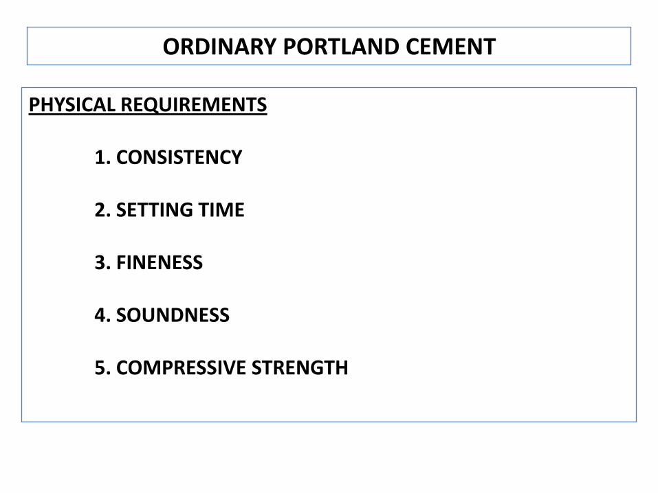
PHYSICAL REQUIREMENTS
1. CONSISTENCY
2. SETTING TIME
3. FINENESS
4. SOUNDNESS
5. COMPRESSIVE STRENGTH
ORDINARY PORTLAND CEMENT

Consistency of Cement : IS 4031 – Part 4
Aim : Determination of Quantity of Water required to produce standard cement paste
Apparatus : Vicat apparatus with Plunger
Percentage of water corresponds to aconsistency which will permit theplunger to penetrate to 5 mm – 7 mmfrom the bottom of mould
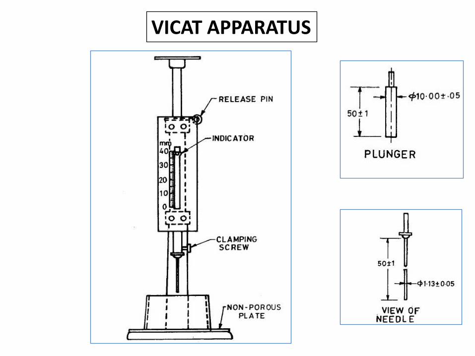
VICAT APPARATUS
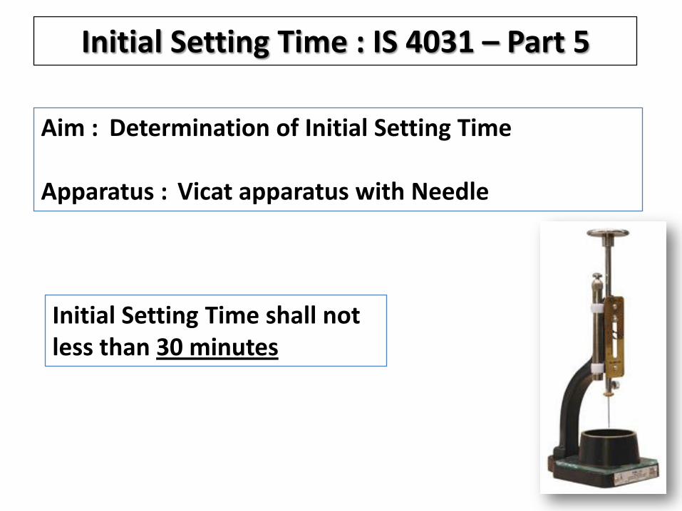
Initial Setting Time : IS 4031 – Part 5
Aim : Determination of Initial Setting Time
Apparatus : Vicat apparatus with Needle
Initial Setting Time shall not less than 30 minutes
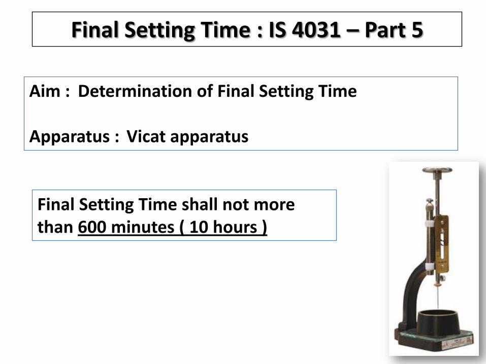
Final Setting Time : IS 4031 – Part 5
Aim : Determination of Final Setting Time
Apparatus : Vicat apparatus
Final Setting Time shall not more than 600 minutes ( 10 hours )

NEEDLE FOR FINAL SETTING TIME

Fineness of Cement
• Fineness is a measure of particle size of Cement
• Particle size between 3 to 32 microns are optimum for cement performance
• Fine Cement reacts quickly with water
• Faster setting & High early strength depends on fineness

Fineness of Cement : IS 4031 - Part 2
Aim : Determination of Specific Surface of Cement
Apparatus : Blaine Air Permeability apparatus
Specific Surface of Cement shall not be less than 225 m2/kg

Soundness of Cement : IS 4031 - Part 3
Aim : Determination of Soundness
Apparatus : Le Chatelier apparatus
Expansion not more than 10 mm

Compressive Strength : IS 4031 – Part 6
Aim : Determination of Compressive Strength
Apparatus : Compression testing machine
DAYSCOMPRESSIVE
STRENGTH (N/mm2)
3 23
7 33
28 43
43 GRADE CEMENT
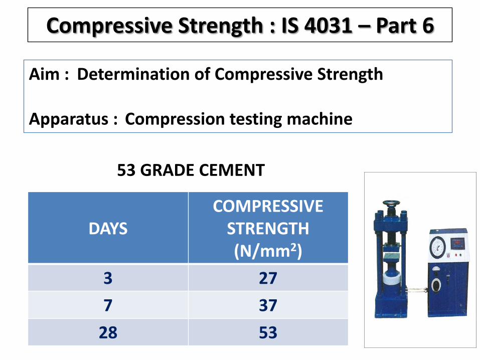
Compressive Strength : IS 4031 – Part 6
Aim : Determination of Compressive Strength
Apparatus : Compression testing machine
DAYSCOMPRESSIVE
STRENGTH (N/mm2)
3 27
7 37
28 53
53 GRADE CEMENT

AGGREGATES
COARSE AGGREGATES : AGGREGATES RETAINED ON 4.75 MM SIEVE
FINE AGGREGATES : AGGREGATES PASSING THROUGH 4.75 MM SIEVE

COARSE AGGREGATE
SPECIFICATIONS (IS : 383)
• Particle size distribution
• Crushing value
• Impact value
• Abrasion value
• Soundness
• Flakiness index
• Elongation index

GRADED COARSE AGGREGATE IS : 383 TABLE 2
IS SIEVE DESIGNATION
PERCENTAGE PASSING
40 mm 100
20 mm 90 – 100
10 mm 25 – 55
4.75 mm 0 – 10
FOR 20 mm NOMINAL SIZE

GRADED COARSE AGGREGATE IS : 383 TABLE 2
IS SIEVE DESIGNATION
PERCENTAGE PASSING
20 mm 100
12.5 mm 90 – 100
10 mm 40 – 85
4.75 mm 0 – 10
FOR 12.5 mm NOMINAL SIZE
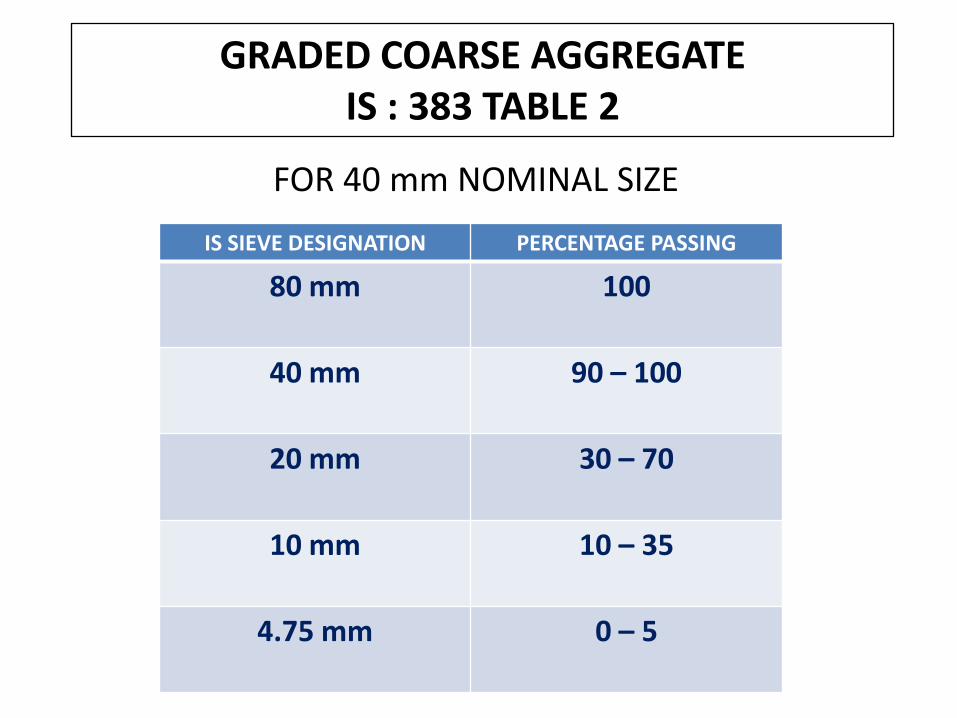
GRADED COARSE AGGREGATE IS : 383 TABLE 2
FOR 40 mm NOMINAL SIZE
IS SIEVE DESIGNATION PERCENTAGE PASSING
80 mm 100
40 mm 90 – 100
20 mm 30 – 70
10 mm 10 – 35
4.75 mm 0 – 5

AGGREGATE CRUSHING VALUEIS : 2386 PART - IV
AGGREGATE CRUSHING VALUE SHALL NOT EXCEED :
30 % FOR CONCRETE WORKS

AGGREGATE IMPACT VALUEIS : 2386 PART - IV
AGGREGATE IMPACT VALUE SHALL NOT EXCEED :
30 % FOR WEARING SURFACES SUCH AS ROADS & PAVEMENTS
45 % FOR OTHER THAN WEARING SURFACES

AGGREGATE ABRASION VALUEIS : 2386 PART - IV
AGGREGATE ABRASION VALUE SHALL NOT EXCEED :
30 % FOR WEARING SURFACES SUCH AS ROADS AND PAVEMENTS
50 % FOR OTHER THAN WEARING SURFACES

FINE AGGREGATE
GRADING REQIREMENT - IS : 383 TABLE 4
SIEVE SIZE ZONE - I ZONE - II ZONE - III ZONE - IV
10 mm 100 100 100 100
4.75 mm 90 – 100 90 – 100 90 – 100 95 – 100
2.36 mm 60 – 95 75 – 100 85 – 100 95 – 100
1.18 mm 30 – 70 55 – 90 75 – 100 90 – 100
600 micron 15 – 34 35 – 59 60 – 79 80 – 100
300 micron 5 – 20 8 – 30 12 – 40 15 – 50
150 micron 0 – 10 0 – 10 0 – 10 0 – 15
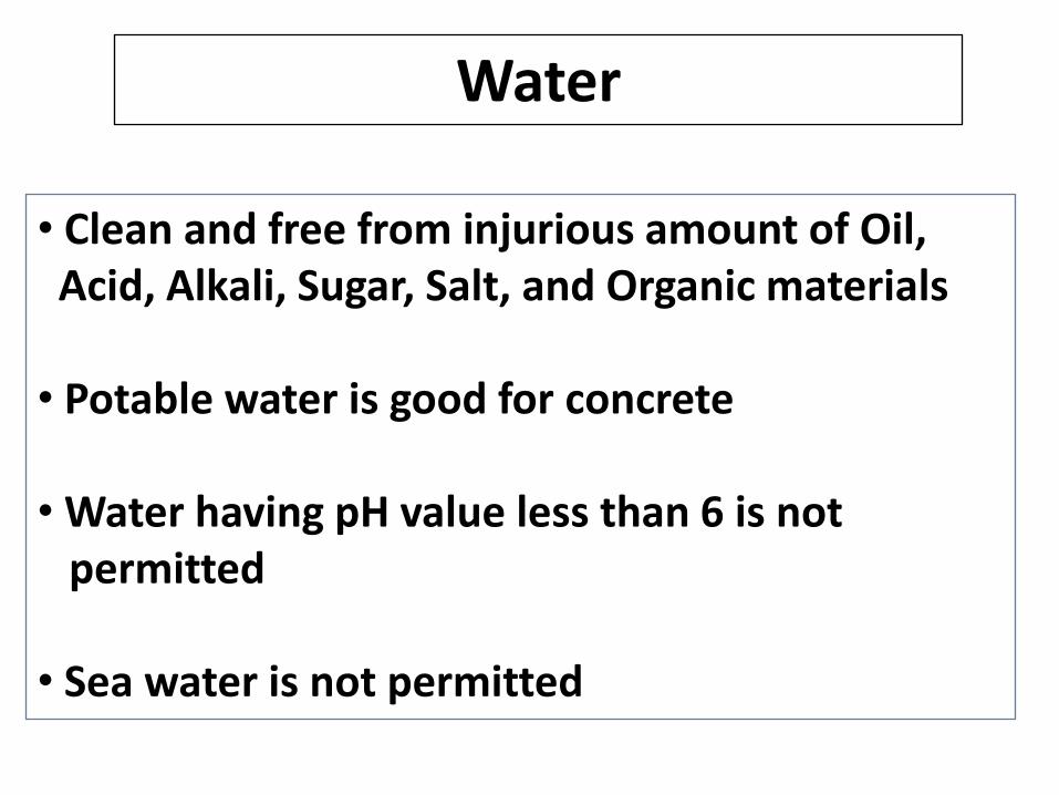
Water
• Clean and free from injurious amount of Oil, Acid, Alkali, Sugar, Salt, and Organic materials
• Potable water is good for concrete
• Water having pH value less than 6 is not permitted
• Sea water is not permitted

CONCRETE – Strength development
Fresh Stage Concrete is Plastic, workable
capable of being moulded
Transition Stage Workability reduces, process
of setting begins
Hardened Stage Concrete becomes stiff and
gains enough strength to support load

Concrete workability – Slump Test
Standard slump cone sizeTop dia = l0 cm Bottom dia = 20 cm.Height = 30 cm
Standard tamping rod Length = 0.6 m Dia = 16 mm.
Test ProcedureConcrete shall be poured in four layers - each layer
25 blows. On removing the cone slowly, the slumped concrete height has to be measured. The difference between this reading and the original height of 30 cm is the slump of concrete.
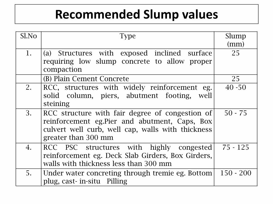
Recommended Slump values
Sl.No Type Slump (mm)
1. (a) Structures with exposed inclined surfacerequiring low slump concrete to allow propercompaction
25
(B) Plain Cement Concrete 25
2. RCC, structures with widely reinforcement eg.solid column, piers, abutment footing, wellsteining
40 -50
3. RCC structure with fair degree of congestion ofreinforcement eg.Pier and abutment, Caps, Boxculvert well curb, well cap, walls with thicknessgreater than 300 mm
50 - 75
4. RCC PSC structures with highly congestedreinforcement eg. Deck Slab Girders, Box Girders,walls with thickness less than 300 mm
75 - 125
5. Under water concreting through tremie eg. Bottomplug, cast- in-situ Pilling
150 - 200

CONCRETE – Properties
• Strength • Compression• Bending• Shear• Torsion• Bond• Fatigue
• Elastic Modulus
• Creep• Shrinkage• Durability
i) Porosityii) Impermeabilityiii) Abrasioniv) Freeze – thaw resistance

CONCRETE – Strength
Number refers to Compressive strength of 150 mm cube, cured in water for 28 days expressed in N/mm2 (Mpa)
Concrete is designated by its compressive strength only
M 30
M refers to Mix
Eg :
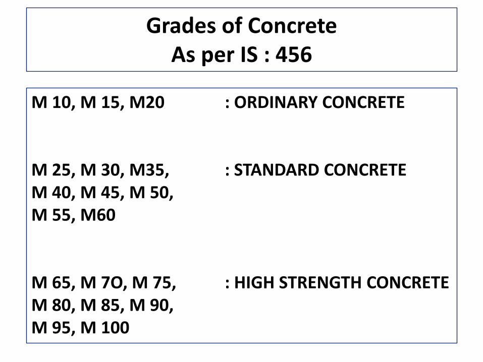
Grades of Concrete As per IS : 456
M 10, M 15, M20 : ORDINARY CONCRETE
M 25, M 30, M35, : STANDARD CONCRETE M 40, M 45, M 50, M 55, M60
M 65, M 7O, M 75, : HIGH STRENGTH CONCRETE M 80, M 85, M 90, M 95, M 100
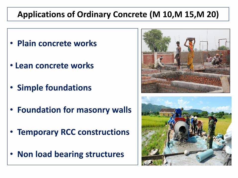
Applications of Ordinary Concrete (M 10,M 15,M 20)
• Plain concrete works
• Lean concrete works
• Simple foundations
• Foundation for masonry walls
• Temporary RCC constructions
• Non load bearing structures

Ordinary Concrete
Cement Fine Aggregate
Coarse Aggregate
Ordinary Concrete
+
+
Water
+

Applications of Standard Concrete (M 25 to M 60)
• Reinforced concrete works• Prestressed concrete works• Prefabricated concrete
elements• Load bearing structures
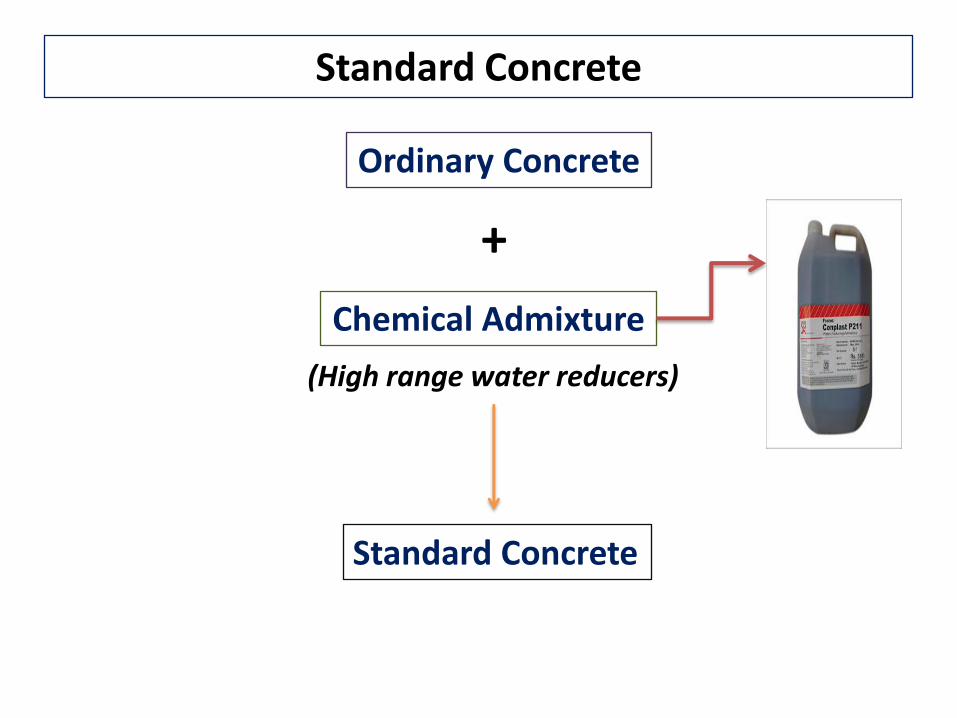
Standard Concrete
Ordinary Concrete
Chemical Admixture
Standard Concrete
+
(High range water reducers)
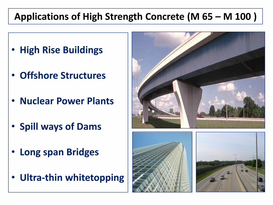
Applications of High Strength Concrete (M 65 – M 100 )
• High Rise Buildings
• Offshore Structures
• Nuclear Power Plants
• Spill ways of Dams
• Long span Bridges
• Ultra-thin whitetopping

Achieving High Strength Concrete
Conventional Concrete
Mineral Admixture
ChemicalAdmixture
High Strength Concrete
+
+

MINERAL ADMIXTURES RECOMMENDED BY IS : 456
• Fly Ash
• Silica Fume
• Ground Granulated Blast Furnace Slag
• Rice Husk Ash
• Metakaolin
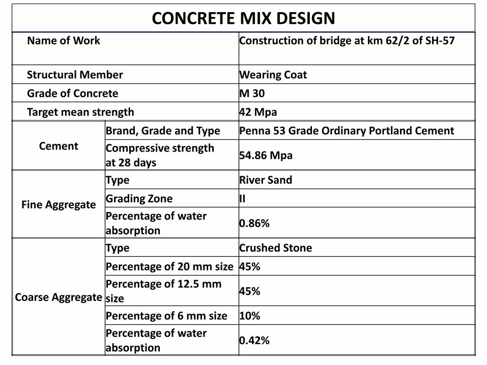
CONCRETE MIX DESIGN Name of Work Construction of bridge at km 62/2 of SH-57
Structural Member Wearing Coat
Grade of Concrete M 30
Target mean strength 42 Mpa
Cement
Brand, Grade and Type Penna 53 Grade Ordinary Portland Cement
Compressive strength at 28 days
54.86 Mpa
Fine Aggregate
Type River Sand
Grading Zone II
Percentage of water absorption
0.86%
Coarse Aggregate
Type Crushed Stone
Percentage of 20 mm size 45%
Percentage of 12.5 mm size
45%
Percentage of 6 mm size 10%
Percentage of water absorption
0.42%

CONCRETE MIX DESIGN
MaterialsQuantity required
for 1 m3 of Concrete
Quantity required for 1 bag of
Cement
CementPenna 53 Grade OPC
390.00 kg 50.00 kg
Fine Aggregate (Dry) River Sand 647.00 kg 83..00 kg
Coarse Aggregate (Dry)
20 mm size 571.95 kg 73.35 kg
12.5 mm size 571.95 kg 73.35 kg
6.0 mm size 127.10 kg 16.30 kg
Water
Free water + Water for Absorption of Fine and Coarse
Aggregates
177.81 lit 22.79 lit
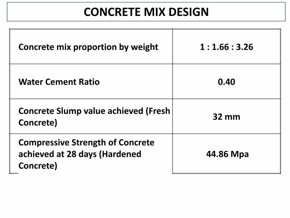
CONCRETE MIX DESIGN
Concrete mix proportion by weight 1 : 1.66 : 3.26
Water Cement Ratio 0.40
Concrete Slump value achieved (Fresh Concrete)
32 mm
Compressive Strength of Concrete achieved at 28 days (Hardened Concrete)
44.86 Mpa

Strength of Concrete Sample
Strength of Concrete in Structure
1 Sample = 3 Cubes
Acceptance Criteria for Strength of Concrete

Minimum Frequency of Sampling
Quantity of Concrete (m3) Number of Samples
1 - 5 1
6 – 15 2
16 – 30 3
31 – 50 4
51 and above4 + 1 for each additional
50 m3 or part

Sampling of Fresh Concrete
• Collect Samples from not less than 5 well-distributed positions immediately after discharge
• Quantity of sample shall not be less than 0.02 m3
• Avoid edge of the concrete mass to avoid segregation

Making and Curing Test Specimen
• Mould shall be thinly coated with oil
• Concrete shall be filled in 3 layers Each layer 5 cm deep
• Compaction with tamping barNumber of strokes per layer : 35

Making and Curing Test Specimen
• Specimen shall be stored at safe place at 220 c to 320c for 24 hours
• After 24 hours, specimen shall be stored in clean water at 270 c ± 20 c until the date of testing
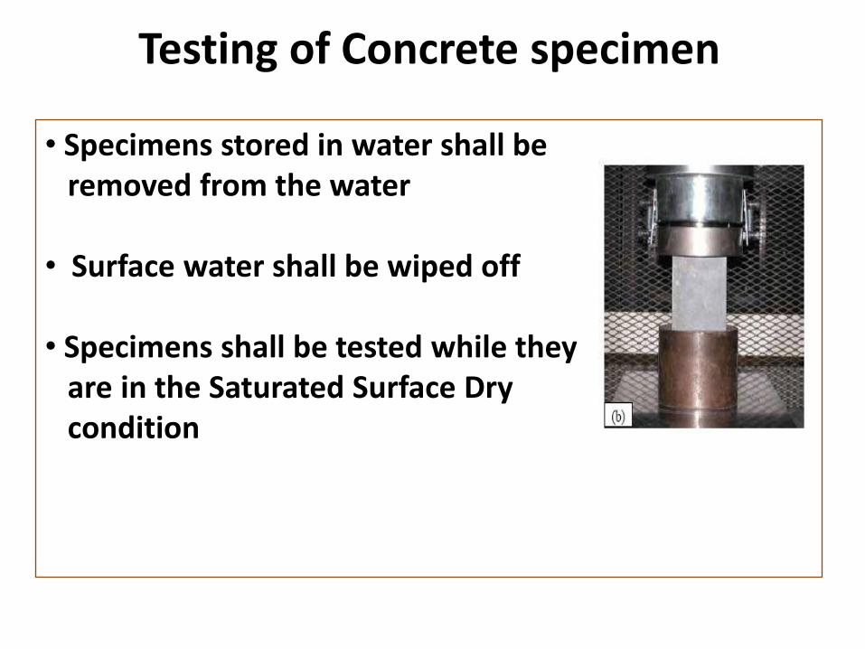
Testing of Concrete specimen
• Specimens stored in water shall be removed from the water
• Surface water shall be wiped off
• Specimens shall be tested while they are in the Saturated Surface Dry condition

Testing of Concrete specimen
• Load shall be applied perpendicular to Cast direction
•Rate of loading : 5.25 kN/sec• Load shall be applied until the specimen breaks down
Load at Failure•Compressive Strength =
Cross sectional area
Top
Top

Acceptance Criteria
Fc1 = Strength of cube 1
Fc2 = Strength of cube 2
Fc3 = Strength of cube 3
Fc1 + Fc2 + Fc3
Fc mean = -------------------3
Fc mean > (Fck + 3)
The values of Fc1 , Fc2 and Fc3 should be
within ± 15 % of Fc mean

Fc1 = Test Result of Sample 1
Fc2 = Test Result of Sample 2
Fc3 = Test Result of Sample 3
Fc4 = Test Result of Sample 4

Fc1 + Fc2 + Fc3 + Fc4
Fc mean = -------------------------4
Fc mean > (Fck + 3)
Fc1 > (Fck - 3)
Fc2 > (Fck - 3)Fc3 > (Fck - 3)Fc4 > (Fck - 3)
Mean of the Four Non - Overlapping
Consecutive Test Results
Condition 1
Condition 2
Acceptance Criteria
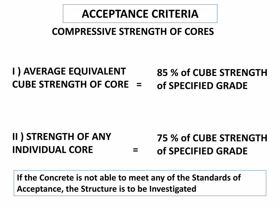
ACCEPTANCE CRITERIA
I ) AVERAGE EQUIVALENT CUBE STRENGTH OF CORE =
II ) STRENGTH OF ANY INDIVIDUAL CORE =
COMPRESSIVE STRENGTH OF CORES
85 % of CUBE STRENGTH of SPECIFIED GRADE
75 % of CUBE STRENGTH of SPECIFIED GRADE
If the Concrete is not able to meet any of the Standards of Acceptance, the Structure is to be Investigated

Factors affecting Compressive Strength
•Water/Cement Ratio
•Cement Content
•Aggregate/Cement Ratio
•Type of Aggregate
•Placing & Compaction
•Curing condition
•Age of Concrete
•Environmental Condition

Steel Reinforcement for Structures
Properties of Steel bars
Properties Fe 415 Fe 415 D Fe 500 Fe 500 D
0.2 Percent Proof StressMinimum (Mpa)
415 415 500 500
Tensile StrengthMinimum (Mpa)
485 500 545 565
ElongationPercentage Minimum(%)
14.5 18 12 16

Prestressed Concrete
Pre tensioned Concrete
•Steel tendons are stressed by Jacks anchored to fixed blocks in the casting yard, Concrete is then placed in moulds or casting beds around these tendons.
•When the concrete has hardened sufficiently, the tendons are released. As they try to return to their original length, large compressive forces are applied to the concrete.
•This process is nearly always carried out in a factory environment and is the usual way of manufacturing precast prestressed bridge girders.

Prestressed Concrete
Post tensioned Concrete
•Tensioning forces are applied to the tendons after the concrete is placed and hardened.
•Ducts are incorporated into the formwork and the concrete is placed around them. After the concrete has hardened, the stressing tendons are threaded through the ducts and are stressed using Jacks.
•A special grout is injected into the ducts around the tendons to provide bond and protection from corrosion. Pos-tensioning is mainly carried out on site although it has been used for special precast girders.

Non Destructive Tests
• Non Destructive tests are used to obtain estimation of the properties of concrete in the structure.
• Non Destructive tests provide alternative to core tests for estimating the strength of concrete in a structure, or can supplement the data obtained from a limited number of core specimens tested.
• These methods are based on measuring a concrete property that bears some relationship to strength.
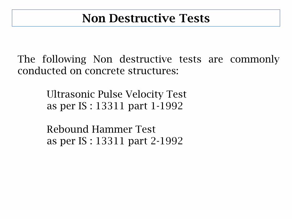
Non Destructive Tests
The following Non destructive tests are commonly conducted on concrete structures:
Ultrasonic Pulse Velocity Testas per IS : 13311 part 1-1992
Rebound Hammer Testas per IS : 13311 part 2-1992

Non Destructive Tests
Ultrasonic Pulse Velocity Test
Non Destructive Tests
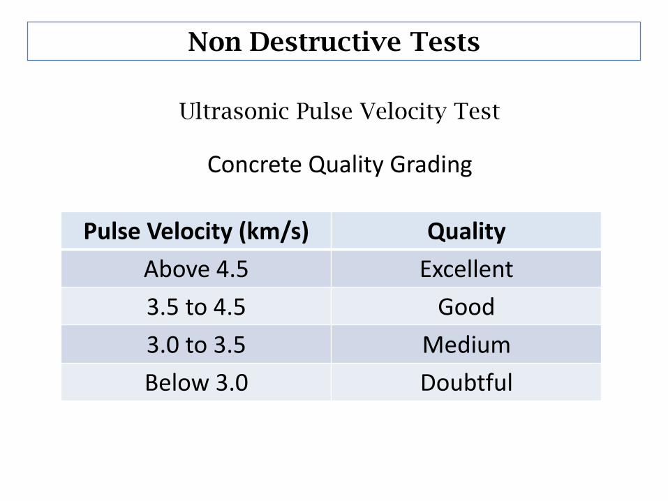
Ultrasonic Pulse Velocity Test
Concrete Quality Grading
Pulse Velocity (km/s) Quality
Above 4.5 Excellent
3.5 to 4.5 Good
3.0 to 3.5 Medium
Below 3.0 Doubtful

Non Destructive Tests
Rebound Hammer Test
POSITION OF REBOUND
HAMMER - VERTICALLY
UPWARDS
POSITION OF REBOUND
HAMMER - VERTICALLY
DOWNWARDS
Inspection of Culverts
•Check whether the vents are choked with debris, vegetable matter, etc., and clear them.
•Check for cracks, distresses in body wall and correct them.
•Check whether the roadway is level on the culvert. If there is a depression suspect failure of pipes, slab, etc., and take action to rectify it.
•Observe during monsoons whether flow of water is proper or whether there is overtopping of the culvert/breach of road adjoining the culvert in which case collect hydraulic particulars, investigate and redesign the culvert for larger discharge.

Inspection of Bridges
•Check the backfill at abutments/approaches and if settlement is seen correct it to a level surface.
•Check abutment, and wing walls for distress.
•Check the slope projection works at abutment and replace / repack loose stones.
•The foundation is to be checked before monsoon for erosion of bed exposing footing, pile cap, pier cap to a larger extent or damage of concrete, abrasion of concrete.
•Aprons / Bed protection works to be ensured to avoid erosion of footings underneath piers and abutments.

Inspection of Bridges
•The abutment and piers are to be checked for cracks, if any, at points just below bearings.
•The deck slab has to be checked for spalling of concrete/delaminating by visual observation and by tapping with a hammer for dull hollow sound. Spalling is due to corrosion of rebars and subsequent pressure caused due to swelling of bars.
•The beams of the deck may be inspected for cracks and the cracks may be identified whether due to shear, bending or otherwise (shrinkage etc.,).
•The bearings may be inspected for proper functioning. Especially, Neoprene pads may be inspected for distresses by way of squeezing out of plates in the bearing, tearing of the polymer or puncture of beam into the bearing or bearing into the concrete.

Inspection of Bridges
•Vegetation present on the structure at drainage spouts are to be removed.
•All drainage spouts are to be cleaned regularly.
•The wearing coat of bridges are to be inspected and all the joints are to be raked, cleared and joint filler board with joint sealant to be applied. Clogging of joints does not allow free movement of the slabs and result in cracks.
•Expansion joints of all bridges are to be checked for proper functioning, cleaned and filled with bitumen sealants wherever applicable.
•The deck and beams near expansion joints and drainage spouts are to be checked for corrosion of bars due to water logging

Repairs and Rehabilitation
Crack Repair
•First identify whether cracks are active or inactive.
•Active means the crack is live either expanding and contracting or extending in length. Inactive cracks are dead cracks which do not vary in size for quite a period of time.
•Inactive cracks may be filled with resins or cement grouts (non-shrink type).
•Filling may be done by simply pounding or pressure injection •
•Cracks of width > 10 mm. may be filled with single size aggregate and then with non shrink cement grouts.

Repairs and Rehabilitation
Crack Repair
•Active Crack:- Cracks to be cleared properly by water jetting, compressed air, etc.,
•Sealing with a flexible sealant or filling with a resin, providing a chase and filling it with flexible sealant.

Repairs and Rehabilitation
Repair of Spalled concrete
• Corrosion is the process of rusting of steel due to action of saline water (chlorides) . Structures near the coast (upto15 kms from sea or creek) and those on backwaters are prone to corrosion.
• The corrosion product (rust or iron oxide) is larger in volume and creates great pressure on the concrete and concrete ultimately cracks. This cover concrete separates, (called delaminating) and falls from the structure (called spalling of concrete).
Repair of Spalled Concrete
• All loose concrete should be chipped off and the spalled area should be cleaned by water jetting.
• Any damaged reinforcement to be replaced with new piece of bar by welding and placing in position. The reinforcement may be protected by applying zinc rich coating.
• Then a bonding agent may be applied, to ensure proper bond between old and new concrete. The epoxy mortar, either ready-to-use or prepared by adding admixtures to normal cement mortar may then be applied layer by layer up to a maximum thickness of 1 inch at a time.

Guniting
• Guniting is used for large scale repairing of structures (such as decks of bridges, columns, beams etc.,)which have damaged extensively.
• Mortar is applied over the area to be required by pressure from a gun. A guniting machine with compressor is required for the above work. It has to he done by skilled workmen as loss of mortar (rebound) will be high.
• For large repairs proper temporary supports, frameworks are to be provided.
Repair of Wearing Coat in Bridges
• When the wearing coat of bridges are extensively damaged, they may be replaced by a new wearing coat.
• The cracks on the wearing coat may be repaired by filling with non-shrink cement based grouts or by filling with sand mastic (a mix of bitumen and sand).