Embed Size (px)
Citation preview

European Journal of Environmental and Civil Engineering Volume 15(SI), 2011, pp. 101-140.
Concrete structures under impact Laurent Daudeville, Yann Malécot Université Joseph Fourier – Grenoble 1 / Grenoble INP / CNRS 3SR Lab Grenoble F-38041, France
[email protected] ABSTRACT. The upcoming need of concrete structures designed against impulsive loading such impact requires analytical treatments comparable to those existing for structures under static loading in spite of a poor state of knowledge of material behaviour in this range of loading. This paper first presents basic relations and empirical formulae used by civil engineers for the design of concrete structures under impacts. Experimental analyses of concrete behaviour under high triaxial stress and high strain rates show that empirical formulae have to be used with caution. Some recent numerical developments are also shown.
RESUMÉ. La demande de sécurité accrue pour les structures en béton vis-à-vis des chargements impulsifs tels les chocs requiert de développer des méthodes de conception comparables à celles qui existent pour les structures sous chargements statiques malgré une connaissance imparfaite du comportement du matériau soumis à ce type de chargement. Ce papier présente dans un premier temps les relations de base et les formules empiriques utilisées aujourd’hui pour la conception des structures en béton sous impact. L’analyse expérimentale du comportement du béton sous fort chargement triaxial ou sous fortes vitesses de solicitations montre qu’il convient d’utiliser ces formules avec précaution. Quelques exemples de travaux récents de modélisation sont montrés.
KEYWORDS: concrete, impact, triaxial stress, modelling, empirical formulae.
MOTS-CLÉS: béton, impact, contrainte triaxiale, modélisation, formules empiriques.

2 European Journal of Environmental and Civil Engineering. Volume 15(SI), 2011.
1. Introduction
The importance of impacts and impulsive loads, such as those occurring in accidental conditions (i): rock fall on a concrete shelter, vehicles or ships in collision with buildings, bridges or offshore infrastructures, aircraft impact on nuclear containments (Figure 1), or those occurring in terrorist or military conditions (ii): missile impact, blast wave due to an explosion, etc., is an increasing preoccupation in the design of reinforced concrete (RC) structures. Impacts cover a wide range of loadings; two limiting cases – hard and soft impacts – will be discussed in the next section. These two limiting cases allow deriving simplified design formulae.
Figure 1. Aircraft impact on a containment building
Nowadays, most of existing methods for the design of concrete structures under impact are based upon empirical formulae and full size experiments. Such design methods are uneconomical and, since recent accidents or terrorist events, there exists a demand for thorough analytical treatments, as carried out for concrete structures under static loading, guaranteeing safety. Impacts and impulsive loadings are mostly extreme loading cases with a very low probability of occurrence during the lifetime of a structure. Material behaviour has to be taken into account up to failure.
This paper will first give a definition of types of impacts and will give an overview of associated design approaches. The main empirical formulae used for the design of shelter concrete structures under hard impact will be given and main features of concrete constitutive behaviour when submitted to high stress states or high strain rates will be discussed. It will be shown that these empirical formulae do sometimes take insufficiently into account the complex non linear behaviour of concrete.

Concrete structures under impact 3
In the design of concrete structures submitted to an impact, the question of the modelling scale arises. For instance in the case of an aircraft impact on a containment building (Figure 1), it is possible to study the perforation of the concrete shelter at the scale of the wall thickness (hard impact due to the engine) or at the scale of the aircraft (soft impact), it is also possible to study the vibrations induced by the impact by modelling the whole building. The paper will conclude on recent advances in the modelling of containment buildings by means of a multi-scale approach coupling a discrete element and a finite element method.
2. Definitions
2.1. Hard and soft Impact
The definition of hard and soft impacts was given in Eibl (1987) and CEB (1988). The studied impact results from the collision of two bodies, one with an initial speed hitting another being at rest. The struck object is usually a building structure that has to be designed against impact. This problem may be reduced to a two colliding masses, m1 and m2, a contact spring with a stiffness k1, in between the two masses to simulate the force which is raised by the counter deforming bodies after contact, and another spring with a stiffness k2 which represents the deformation and activated resisting force of the structure. In general both springs have nonlinear force-deformation relationships (Figure 2).
Figure 2. Simple mechanical model of an impact by means of a two-mass system
The two-mass system is governed by the following differential equations:
[ ]
[ ]
=+−−
=−+
0)t(xk)t(x)t(xk)t(xm
0)t(x)t(xk)t(xm
2221122
21111
&&
&&
[1]

4 European Journal of Environmental and Civil Engineering. Volume 15(SI), 2011.
In case where x1>>x2, i.e. the deformation of the projectile is much greater than the deformation of the impacted structure, then with F(t)=k1x1(t), both equations [1] are decoupled to give:
=+
=+
)t(F)t(xk)t(xm
0)t(xk)t(xm
2222
1111
&&
&&
[2]
The first equation of [2] is now an independent equation to determine F(t), while the second gives the deformation of the structure under an independently acting force F(t).
This case, considering that the resisting structure remains undeformed, so that the kinetic energy of the striking body is completely transferred into deformation (x(t)=x1(t) and V(t)= 1x& ) of the striking body, is called soft impact (Figure 3). Different examples will be given further for the estimation of the contact force F(t).
Figure 3. Soft impact
The limiting counterpart (x1(t)<<x2(t)) is called hard impact (Figure 4) and occurs when the striking body is rigid and the kinetic energy of the striker is completely (the residual velocity V(t)=0) or partially (the residual velocity V(t)≠0) absorbed by deformation of the struck structure.
Figure 4. Hard impact
V(0) V(t)
Concrete structures under impact 5
Kœchlin and Potapov (2009) proposed a very interesting and convincing classification of soft/hard impacts based on material properties and kinetic energy of the striker.
2.2. Terminology of impact effects on a concrete slab
Kennedy (1976) has given the terminology generally used when describing local missile impact effects. He suggested that seven phenomena are associated with missile impact effects on concrete targets, as shown in Figure 5: (a) penetration, (b) cone cracking and plugging, (c) spalling - ejection of target material from the proximal face of the target - , (d) radial cracking associated to (i) proximal face and (ii) distal face, (e) scabbing - ejection of fragments from the distal face of the target - , (f) perforation, (g) overall structural responses and failures.
Figure 5. Missile impact effects on concrete target (from Li et al. 2005).
3. Reference impact tests
The methods outlined in the following sections for assessing the results of soft and hard impacts on concrete structures are based on numerous experimental and analytical studies essentially carried out by national nuclear safety agencies, subcontractors or nuclear energy companies.
6 European Journal of Environmental and Civil Engineering. Volume 15(SI), 2011.
The effect of an impact on a structure has been studied since the mid-17th century. These studies have mainly concerned military applications, i.e. the hard impact (bullets, missiles...). Recently, the safety requirements of nuclear power plants have led to significant increase of knowledge about the local effects of a structure subjected to an impact, including the case of soft impact. Laboratory tests on a small scale prototype and full scale tests were performed to study concrete behaviour and the response of structures subjected to such solicitations. Based on these experimental results, several empirical formulae have been developed to predict local effects of impact. The main series of tests conducted in the 1970s and 1980s are described below. Koechlin and Potapov (2009) have classified these tests by means of their soft/hard impact criterion.
CEA-EDF perforation tests
Gueraud et al. (1977), Fiquet et al. (1977), Goldstein et al. (1977), Berriaud et al. (1978) reported tests performed for the prediction of the ballistic limit of RC slabs, i.e. the perforation condition.
EDF soft impact tests
Dulac et al. (1981) performed tests for the analysis of the non linear response of concrete slabs submitted to soft impacts.
Meppen tests
These tests were performed in the “Wehrtechnische Dienststelle für Waffen und Munition” German army research center close to the city of Meppen. They consist in a series of 21 tests of RC slabs under the impact of highly deformable projectiles. A main objective of these tests was the improvement or the validation of methods applied to the treatment of aircraft impact load. These tests have been intensively used by different authors for the validation of numerical methods for the prediction of damage in concrete slabs submitted to soft impacts. The tests and some of their use are described in Jonas et al. (1979), Nachtsheim and Stangenberg (1981), Jonas et al. (1982), Nachtsheim and Stangenberg (1982), Rüdiger and Riech (1983).
Kojima tests (1991)
This paper describes a series of missile impact tests of RC slabs. A total of 12 tests were performed varying the targets and missile conditions. The following conclusions were obtained in the tests: (1) the degree of damage from a soft-nosed missile is less than that of a hard-nosed missile; (2) steel lining is effective in preventing scabbing; (3) the impact resistance of a double RC slab is inferior to that of a single RC slab in case of a hard-nosed missile, and almost equal in case of a soft-nosed missile; and (4) the existing formulae for evaluating critical thicknesses against perforation and scabbing give slab thicknesses on the conservative side.

Concrete structures under impact 7
Ohno et al. tests (1992)
Five types of projectiles with different magnitudes of axial strength were employed for the impact tests in order to evaluate the transition between soft and hard impacts. The aim was the study of the conservatism of empirical perforation formulae when used with soft missiles.
Sugano et al. tests (1993)
Different campaigns of tests were performed in collaboration with the Sandia National Laboratories.
- reduced scale tests: 48 deformable and 25 rigid missiles of different sizes;
- full scale tests: 1 deformable missile and 4 impacts of aircraft engines;
- a large scale crash test in which a F4-Phantom military jet with a weight of 19 tons impacted a rigid RC wall at a velocity of 774 km/h (Figure 6).
Figure 6. Full-scale aircraft impact test (Sugano et al. 1993)
These tests allowed concluding that reduced scale tests give similar results to full scale tests and that aircraft engines, as well as the fuselage, can be considered as deformable.
Turbine missile impacts
Turbine missile impact tests were performed and analysed by Romander and Slitter (1984) and Walter and Wolde-Tinsae (1984) in order to assess the empirical formulae for hard impacts.

8 European Journal of Environmental and Civil Engineering. Volume 15(SI), 2011.
4. Soft impact
In case of an aircraft impact, Riera (1968) considered that the striker (a tube representing the fuselage) could be considered as a two body system (Figure 3): a crushed tube in contact with the structure and with no velocity and a tube with a velocity V(t) and a mass m that represents the striking mass. The contact force is due to the momentum variation:
F(t) = dt
)mV(d=m
dt
dV+V
dt
dm
The first term is assumed to be equal to the elastoplastic buckling force due to the crushed tube along the length x(t): Fp(x(t)).
Considering µ(x(t)) the mass per unit length of the tube, the second term can be written:
dt
dm= µ(x(t)) V(t)
With x(t) = ∫ ττt
0
d)(V
Thus, the contact force results of a term due to elastoplastic buckling Fp and a term due to inertia:
F(t) = Fp(x(t)) + µ(x(t)) V2(t) [3]
The elastoplastic buckling force Fp may be obtained by analytical formulae or by finite element calculations. It’s value is generally considered as constant, i.e. independent of x(t).
If the target (the struck structure) of masse mt is not at rest and has a velocity Vt in the axis of the striker, the contact force becomes:
F(t) = Fp(x(t)) + µ(x(t)) (V2(t)- 2tV ) - mt
dt
dVt [4]
Arros et al. (2006) analyzed a Boeing 747-400 impact to a nuclear building using LS-DYNA software representing the loading by the Riera method and by modelling the crash of a plane to the structure (Figure 7). The authors concluded that modelling the crash with aircraft model impacting the target structure results in more high frequency content in the building response than shown by Riera force time history method (Figure 8). The results obtained with the Riera approximation are correct,

Concrete structures under impact 9
the area under the two curves match within 2%, but they are very sensitive to the assumptions associated with loading area.
Figure 7. Model of the fictitious nuclear building and of the 747-400 airliner (Arros et al., 2006)
Figure 8. The target Riera force history (thicker, smoother curve) and the reaction history at rigid target from LS-DYNA run (Arros et al., 2006)
The force given by [3] was compared to experimental results and some authors proposed to modify Eq. [3] (Sugano et al. (1993), Abbas et al. (1995)). Sugano et al. analysed results of tests performed at Sandia national laboratories and fixed the Riera formula [3] by introducing a coefficient α of “effective mass on impact” [5]. Best results were obtained with α = 0.9. The Riera formula [3] is then conservative.
F(t) = Pf(x(t)) + αµ(x(t))V2(t) [5]

10 European Journal of Environmental and Civil Engineering. Volume 15(SI), 2011.
5. Hard impact
The methods outlined in this section for assessing the results of hard impact on concrete structures are based on numerous experimental studies presented in section 3. Li et al. (2005) reviewed existing empirical formulae and Buzaud et al. (2007) assessed the relative performances of classical and more recent empirical formulae.
5.1. Penetration depth prediction
Petry formula (Kennedy, 1976) gives the penetration depth xp of a rigid missile into a semi-infinite concrete slab, it was developed in 1910 in USA:
215000
V+1logAK12=x
2
10ppp [6]
With xp (m) penetration depth; V impact velocity; Ap missile section pressure (psi), Kp concrete penetrability coefficient, it depends upon the strength of concrete and on the degree of reinforcement.
The Petry formula was modified by different authors in order to better take into account the concrete strength. See Li et al. (2005) for more details.
Based on the penetration depth, for instance calculated with [6], Amirikian (1950) suggested that the perforation thickness e and the scabbing thickness hs could be obtained from:
e = 2 xp and hs = 2.2 xp [7]
Thus Eq. [6] and [7] give, in terms of missile velocity, the perforation velocity Vp (ballistic limit) or the scabbing limit.
The Ballistic Research Laboratory developed in 1941 an improvement of Petry formula. A modified expression was given by Chelapati et al. (1972):
1.330.23
c
3p
Vdd
M
f
101.33=
d
x
− [8]
With d (m): diameter of the projectile; M (kg): mass of the projectile; fc (Pa): unconfined compressive strength of concrete.
Based on the above penetration depth, the perforation e and scabbing hs limits are given by Chelapati et al. (1972) as:
e = 1.3 xp and hs = 2 xp

Concrete structures under impact 11
Forrestal et al. (1994) proposed a model for the penetration depth into a concrete target. This model is applicable for a wide range of penetration depth. It is based upon a cavity expansion theory (Forrestal et al., 1996). Based on the model of Forrestal et al. and taking into account some experimental observations, Li and Chen (2003) have proposed a semi-analytical formulation of penetration depth which is dimensionally homogeneous and defines the nose shape factor analytically:
( )( )( )( ) I
π
4k
N/I+1
4N/kπ+1=
d
x p for k
d
x p ≤
( )( ) k+
4N/kπ+1
N/I+1lnN
π
2=
d
xp
for k>
d
x p
Where I is the impact function introduced by Haldar and Hamieh (1984) and N is the nose geometry function:
−c
3
2
0.5c fd
MV
f72
1=I and
ρ 3* d
M
N
1=N [9]
N* is the nose shape factor, the sharper the nose, the lower this coefficient. The definition and the calculation of N* are given in Li and Chen (2003). k is the penetration capacity coefficient.
=ΨΨ
−
=ΨΨ+=
Rradiusofnosecalhemispheriaford
Rwith
8
11
llengthofnoseconicaford
lwith
41
1
N
2
nn
2*
( )Ψ+0.707=k k = 0.707 corresponds to a flat nose missile.
5.2. Perforation prediction
From a series of drop-weight and air gun tests performed by CEA and EDF and for targets with symmetrical bending reinforcement meshes close to the faces of a slab, Berriaud et al. (1978) proposed a perforation limit formula:
5.1375.0c
125.0
75.0p
5.0
df
VM82.0
d
e
ρ=

12 European Journal of Environmental and Civil Engineering. Volume 15(SI), 2011.
With Vp (m/s): ballistic limit; d (m): diameter of the projectile; M (kg): mass of the projectile; e (m): thickness of the concrete wall; ρ (kg/m3): density of concrete; fc (Pa): unconfined compressive strength of concrete.
From the previous equation, the CEA-EDF ballistic limit or perforation velocity Vp (m/s) is then:
3/222/1
c6/1
p M
def3.1V
= ρ [10]
Ma is the reinforcement density. The range of variables over which formula [10] has been identified is: 20 < Vp < 200 m/s; 30 < fc < 45 MPa; 0.3 < e/d < 4 and 120 < Ma < 300 kg/m3.
Fullard et al. (1991) modified the CEA-EDF formula [10] to take into account the reinforcement quantity:
3/2
3/222/1
c6/1
p )0.3+(rM
def3.1V
= ρ [11]
Where r is the percentage of reinforcement described by the percentage each way in each face (% EWEF, Figure 9).
Figure 9. Calculation of the percentage of reinforcement (CEB, 1988)
The range of variables over which formula [11] has been identified is: 45 < Vp < 300 m/s; 15 < fc < 37 MPa; 0 < r < 0.75; 0.33 < e/d < 5.
The CEA-EDF formula [10] was improved in order to extend its validity range, in particular concerning concrete strength, the reinforcement ratio and the projectile nose (Berriaud et al. 1993):
2/1
c
c
a
a23/42
3/1c
2p
00 f
f65.0
M
M35.0N
M
def9.1V
−γ
+
ρ= [12]
e r =
ce
a
c each rebar area = a

Concrete structures under impact 13
With Vp, d, M, e, ρ, σ, Ma defined as previously; Ma0 = 200 kg/m3 reference steel reinforcement density; fc0 = 36 MPa reference compressive strength of concrete; γ a function of the number of steel layers (γ = 0.7 for 2 steel layers and γ = 0.1 for 4 steel layers); N a function of the nose geometry (Ν = 1 for a flat nose, N = 1.18 for a hemispherical nose).
The range of variables over which formula [12] has been identified is: 15 < Vp < 300 m/s; 15 < fc < 80 MPa; 0.3 < e/d < 4; 0 < Ma < 300 kg/m3.
Buzaud et al. (2007) compared empirical formulae [10]-[12] to a common database of 151 perforation tests. These authors concluded that the EDF-CEA formula [12] presents a significant advantage in terms of precision but its range of application does not concern new Ultra High Performance Concrete. He also noticed that none of the tested formulae include the effect of shear reinforcement.
6. Constitutive behaviour of concrete under high triaxial stress state
When subjected to an impact, concrete is generally submitted to both a multiaxial state of stress characterized by a high mean stress and high strain rates. According to the empirical formulae [8]-[12] presented in section 5, the only material parameter governing the impact resistance of concrete structures is the uniaxial unconfined compressive strength of concrete fc. This is a general remark, according to design codes the calculation of concrete structures is based on the unconfined compressive strength of concrete after 28 days of ageing, fc28. Based on empirical relations, the majority of other characteristics can be deduced from fc28 (tensile strength ft28, Young's modulus E, etc…). Lots of concrete 3D constitutive models also use fc28 to scale the concrete 3D strength criterion in the meridian cross section (Kang and Willam, 1999; Liu and Foster, 2000; Grassl and Jirasek, 2006; Papanikolaou and Kappos, 2007).
This section concerns the concrete behaviour under extreme loading situations (ballistic impacts, penetration). During such loadings, concrete material is subjected to high-intensity triaxial stress states. Gran and Frew (1996) have performed impact tests on concrete targets having an unconfined compressive strength of 43 MPa. The projectile was a 50mm diameter steel sharp penetrator weighting 2.3 kg and was launched at 315 m/s. These authors have measured radial stresses at various depths and radii. They have shown that the maximum radial stress was about 400 MPa and, according to analytical calculations, the mean stress was of the order of 1 GPa. In order to analyze the behaviour of concrete under such level of stresses, triaxial tests on plain concretes have been performed, using a large capacity triaxial press. Stress levels over passing one GigaPascal have been reached (Gabet et al. 2006, Gabet et al. 2008, Vu et al. 2009, Dupray et al. 2009, Poinard et al. 2010, Dupray et al. 2010, Malecot et al. 2010).

14 European Journal of Environmental and Civil Engineering. Volume 15(SI), 2011.
The purpose of this section is to present the experimental results of this program which show that fc28 is a very poor indicator of the high-pressure mechanical response of concrete. Contrary to what is observed in simple compression, when placed under high confinement, concrete behaves like a granular stacking. There is not any effect of the level of the cement matrix strength whereas the saturation ratio exerts a major influence.
6.1. Experimental set-up
6.1.1. Triaxial cell
The tests have been conducted with a high-capacity triaxial press that allows loading a cylindrical concrete specimen 7 cm in diameter and 14 cm long. This press is able to generate a maximum confining pressure of 0.85 GPa and an axial stress of 2.3 GPa. A displacement sensor located in the press is used to control the axial jack displacement, while a load sensor and pressure sensor placed inside the confinement cell display the stress state of the sample. The confining pressure and axial jack displacement are servo-controlled, which offers the possibility of creating several possible loading paths (Gabet et al. 2006, Gabet et al. 2008).
In this paper, compressive stresses and contraction strains are assumed to be positive; σx is the principal axial stress, p the pressure inside the confining cell, σm the mean stress and q the principal stress difference (deviatoric stress).
3
p2xm
+=
σσ and q = σx - p [13]
All tests have been conducted in following the same kind of loading path. The triaxial compression test begins with a hydrostatic test. Once the desired confinement has been reached, the specimen is then loaded axially while holding the confining pressure constant. Note that for most of the tests the maximum deviatoric stress reached value has not been imposed. It is a result of the test.
6.1.2. Concrete samples: fc28 and Sr
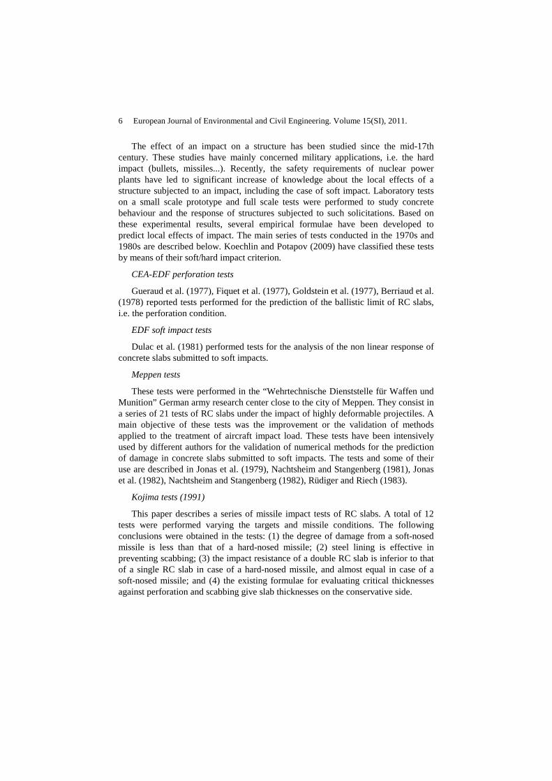
In order to study the effect of fc28, from the composition of a reference ordinary concrete (fc28=29MPa), two other concretes have been produced with fc28 equal to 21 MPa and 57 MPa, respectively. These three concretes have different water/cement ratio (W/C), but their aggregates skeletons are almost identical (see composition on Table 1).
Besides, to evaluate the effect of the saturation ratio Sr, tests have been conducted on dried, wet and saturated samples, for the C29 concrete. After some 4 months of conservation in water, the “dried” specimens are placed in a drying oven, at a temperature T of 50°C and relative humidity RH of 8%, for a period lasting between 3 and 6 months. The saturation ratio of the “dried” concrete tested in this study is approximately 11%. The “saturated” specimens are conserved in water
Concrete structures under impact 15
between 6 and 10 months, after which they are wrapped in the multilayer membrane, just prior to the triaxial test. Lastly, the “wet” specimens are conserved in water and then a few days in the ambient laboratory atmosphere (a T value near 18°C and 40% RH) during the instrumentation procedure (Vu et al. 2009a).
Strain measurements are performed by use of an LVDT (Linear Variable Differential Transformer) axial sensor, along with one axial and two circumferential gauges. Given the porous nature of concrete, this high level of confinement has necessitated developing a multilayer protective membrane around the sample; this element is composed of 8 mm of latex and 2 mm of neoprene (Vu et al. 2009b).
Concrete composition and mechanical properties C57 C29 C21 0.5/8 "D" gravel (kg/m3) 1000 1008 991 1,800 µm "D" sand (kg/m3) 832 838 824 CEM I 52.5 N PM ES CP2 cement (Vicat) (kg/m3) 349 263 226 Water (kg/m3) 136 169 181 Sikafluid Superplasticizer (kg/m3) 4.5 0 0 W/C ratio 0.39 0.64 0.80 Density (kg/m3) 2322 2278 2252 Average slump measured using the Abrams cone (cm) 7 6.9 14 Unconfined compression strength after 28 days fc28 (MPa) 57* 29 21*
Table 1. Compositions and mechanical properties of concretes C21, C29, C57; *Calculated values.
6.2. Test results
Figure 10 shows the results for the unconfined compression tests carried out on the four types of concrete samples. As it was expected, an increase in the Young's modulus E and ultimate stress of the concrete fc can be observed with a decrease in Water/Cement ratio of the concrete mixture. Figure 10 also reveals that the saturation ratio of the sample has a very slight influence in unconfined compression compare to the water/cement ratio.
Figure 11 shows the hydrostatic part of triaxial tests conducted at a confining pressure of 650MPa. This figure reveals that beyond 400 MPa of confinement, the volumetric behaviour curves of dried concretes (C21, C29 or C57) run parallel, which suggests that the difference in incremental volumetric strains of these three concretes is significant only at low confinement levels. These phenomena are more obvious on Figure 12 which focuses on the hydrostatic behaviour of the same samples beyond a confining pressure of 400 MPa.

16 European Journal of Environmental and Civil Engineering. Volume 15(SI), 2011.
Figure 10. Axial stress σx vs. strain components εx and εθ for unconfined compression tests carried out on 4 types of 8 months aged concrete samples : C57 fc28=57MPa and Sr=11% (♦); C29-11% fc28=29MPa and Sr=11% (grey diamond); C21 fc28=21MPa and Sr=11% (◊);C29-85% fc28=29MPa and Sr=85% (+); fc28 : concrete strength in uniaxial compression after 28 days of ageing.
Figure 11. Mean stress σm vs. volumetric strain εv for the hydrostatic part of triaxial tests conducted at a confining pressure of 650 MPa on four types of concrete samples: C57 fc28=57MPa and Sr=11% (♦); C29-11% fc28=29MPa and Sr=11% (grey diamond); C21 fc28=21MPa and Sr=11% (◊); C29-85% fc28=29MPa and Sr=85% (*).
85%

Concrete structures under impact 17
Figure 12. Mean stress σm vs. volumetric strain variation above 400MPa ∆εv = εv - εv400MPa for the hydrostatic part of triaxial tests conducted at a confining pressure of 650 MPa on four types of concrete samples: C57 fc28=57MPa and Sr=11% (♦); C29-11% fc28=29MPa and Sr=11% (grey diamond); C21 fc28=21MPa and Sr=11% (◊); C29-85% fc28=29MPa and Sr=85% (*).
Figure 13. Stress deviator q vs. strain components εx and εθ for deviatoric part of triaxial tests conducted at a confining pressure of 650 MPa on four types of concrete samples: C57 fc28=57MPa and Sr=11% (♦); C29-11% fc28=29MPa and Sr=11% (grey diamond); C21 fc28=21MPa and Sr=11% (◊); C29-85% fc28=29MPa and Sr=85% (*).
Figure 13 shows the deviatoric part of triaxial tests conducted at a confining pressure of 650 MPa. The results indicate that the deviatoric behaviour curves of

18 European Journal of Environmental and Civil Engineering. Volume 15(SI), 2011.
0
5
10
15
20
25
30
35
0 5 10 15 20 25 30 35
q/f
c28
σm/fc28
fc28=29MPa Sr=70%
fc28=29MPa Sr=85%
fc28=29MPa Sr=100%
fc28=21MPa Sr=11%
fc28=57MPa Sr=11%
fc28=29MPa Sr=11%
dried concretes (C21, C29 or C57) practically overlap. The strength gap between these concretes is not anymore visible. The incremental behaviour of concretes becomes then independent from their unconfined compressive strength beyond a given confining pressure.
On the contrary, the presence of free water in the sample seems to affect the volumetric stiffness only under high confinement. For a mean stress greater than around 200 MPa, the volumetric behavior of the wet concrete becomes stiffer than that of dried concrete (Figure 11). A relative difference of about 25% between the volumetric strains of dried and saturated samples at a mean stress of 650MPa can for example be noted. For these stress levels, the volumetric strains become significant in comparison with the initial air volume of the sample. The initially wet samples thus trend toward a degree of humidity close to saturation. The pore pressure developing within the material rises and exerts a significant impact on the measured stress.
The presence of free water in the sample also reduces a lot the strength capacity (Figure 13). The resistance capacity of the dried samples is clearly higher. As such, no peak deviatoric stress is reached in the tests conducted on dried concrete at these high confinements. These results may be explained by the cohesion loss of the cementitious matrix, which provides the concrete with behaviour of the non-cohesive granular material type. The increase in dried concrete shear strength with confining pressure is thus explained by the friction existing between stacking grains. Limitation of the same strength observed for saturated concrete is probably due to pore pressure, which develops similarly to what is found in undrained soils.
Figure 14. Limit states of concretes C21 (Sr=11%), C29 (Sr=11%, 70%, 85% or 100%) and C57 (Sr=11%): Deviatoric stress q/fc28 vs. the mean stress σm/fc28.

Concrete structures under impact 19
0
0.5
1
1.5
2
0 100 200 300 400 500 600 700
q/q
C29
-11%
p [Mpa]
C29-100%
C29-85%
C29-70%
C21-11%
C57-11%
Figure 14 summarizes the strain limit state of concretes C21, C29 and C57, within the (σm/fc28,q/fc28) deviatoric plane for all tests performed. It can be observed that beyond a mean stress of around 5fc28, the loading capacity of dried concrete strongly increases in a quasi-linear manner with respect to the mean stress whereas the ones of wet or saturated concretes almost remain constant. Figure 14 also shows, on the one hand, that at low mean stress level (below 5fc28) all the concretes are following the same curve whatever Sr or fc28 values are. On the other hand, beyond this critical mean stress (over 5fc28), one can observe that the limit states are very scattered depending on Sr or fc28 values. This last point shows that fc28 is poorly link to the loading capacity of concrete under high confinement.
Figure 15. Relative limit states of concretes C21 (Sr=11%), C29 (Sr=70%, 85% or 100%) and C57 (Sr=11%): Relative deviator q/q29-11% vs. the confining pressure p, where q29-11% is the deviatoric stress associated with the limit state of reference concrete C29 for Sr=11%.
Figure 15 shows the relative limit state of concretes C21, C57, C29-70%, C29-85% and C29-100% to that of the reference concrete C29-11% in the (p,q/qC29-11%) plane. qC29-11% is the limit deviator obtained for the reference concrete C29-11% at an identical confining pressure. This presentation in terms of deviator relative to that of the reference concrete provides a better perception of the both the effect of the simple compressive strength at low confinement and the effect of the saturation ratio at high confinement. For low mean stress levels, the limit state of the concrete is heavily dependent on the cement matrix strength. This result was obviously the expected one. In contrast, the same figure also shows that this dependence of concrete limit state on fc28 decreases rapidly as mean stress rises. Beyond a critical confining pressure, the limit state curve actually becomes independent of fc28.
Conversely, at a low level confining pressure, it is found that the limit states of the dried, wet and saturated samples all lie very close to one another (Figure 15).

20 European Journal of Environmental and Civil Engineering. Volume 15(SI), 2011.
This result should come as no surprise since at such stress levels, concrete behaviour is governed by a still cohesive character. The presence of water in the sample does not exert therefore a very significant effect on the limit state. For higher confinement levels, the effect of water becomes predominant. The increase in peak deviatoric stress with respect to mean stress remains very low for the saturated samples. The shear strength of the dried concrete is then equal to 4 times the one of the saturated concrete for a confining pressure of 650MPa, whereas their unconfined compressive strength is almost the same. Again, this phenomenon is likely explained by a pore pressure effect similar to that observed for an undrained granular material.
6.3. Conclusion
The context of this study has focused on identifying concrete behaviour under severe triaxial loadings. In order to reproduce high stress levels with well-controlled loading paths, static tests were carried out on concrete samples through the use of a very high-capacity triaxial press. The test results presented in this article relate more specifically to the effect of the uniaxial compression strength, fc28, on concrete behaviour under high confinement. Based on an ordinary reference concrete (fc28=29MPa), two other concretes with fc28 equal to 21 MPa and 57 MPa respectively were produced. Besides, to evaluate the effect of the saturation ratio, Sr, tests have been conducted on both dried, wet and saturated samples, for the C29 concrete.
As expected, the concrete behaviour is strongly dependent on the unconfined compression strength at low confinement levels whereas it is only slightly dependent on its saturation ratio. On the contrary, under high confinement, once the cement matrix has been strongly damaged, the volumetric behaviour and deviatoric behaviour of the concrete both become insensitive to fc28. Hence, concrete which have unconfined compression strength equal to 21MPa or 57MPa have limit-states curve that tend to be identical beyond a critical mean stress. Conversely, the saturation ratio of concrete takes on major importance under such confinements. The hydrostatic behaviour of very wet or saturated concrete clearly becomes stiffer than that of dried concrete. Moreover, the limit shear strength value is directly correlated with the concrete saturation ratio. The more the concrete is dried, the more its shear strength is important. For a confining pressure of 650 MPa, the shear strength of dried concrete is thus divided by a factor of 4 when the concrete is saturated, dropping from 900 MPa to just 230 MPa.
In summary, the test results provided in this article show that under high confinement, the concrete behaves like a non-cohesive granular stacking, on which the cement matrix strength of the fresh concrete no longer exerts any influence. It becomes insensitive with fc28 whereas the saturation ratio exerts a major influence, particularly on both the concrete strength capacity and the volumetric stiffness. According to this new result, the range of application of penetration formulae [10]-[12] presented in the previous section must be examined with caution.

Concrete structures under impact 21
From an application standpoint, on the one hand, these results highlight the very small advantages to be gained by increasing the cement concentration in concretes for the purpose of raising their strength capacity to resist to extreme loadings. One the other hand it seems necessary to evaluate and to take into account the saturation ratio to evaluate precisely the vulnerability under impact of massive concrete infrastructures.
In the future, it will be necessary to evaluate the effect of the concrete porosity on the validity of these results. More specifically, do the above conclusions remain valid for very low porosity and/or high performance concretes ?
7. Constitutive behaviour of concrete under high strain states
When subjected to a dynamic loading such an impact, concrete is submitted to strain rates depending on the kind of loading and the location into the structure (from rest far from the impact location to high strain rates close to the impact). Figure 16 gives some very crude estimates of strain rates which occur during various types of loading. A reliable prediction of the structural response of concrete under impact requires the knowledge of the strain rate dependency of concrete constitutive behaviour. Since most investigations are based upon laboratory tests of concrete samples under compression or tension at constant strain rate and since test results strongly depend on the concrete mix design or the presence of free water in the material, the state of knowledge is still incomplete and research is still in progress.
Figure 16. Typical strain rates for various types of loading (Bischoff and Perry, 1991).
7.1. Experimental background
Various experimental devices have been used to explore a wide range of strain rates, as described in (Bischoff and Perry, 1991 ; Gopalaratnam et al. 1996). Compression and direct tension tests have been performed, from static loading up to strain rates of 10-1 s-1 with a hydraulic testing machine, whose displacement control capabilities or stiffness are limiting. Charpy impact tests were commonly used, and
22 European Journal of Environmental and Civil Engineering. Volume 15(SI), 2011.
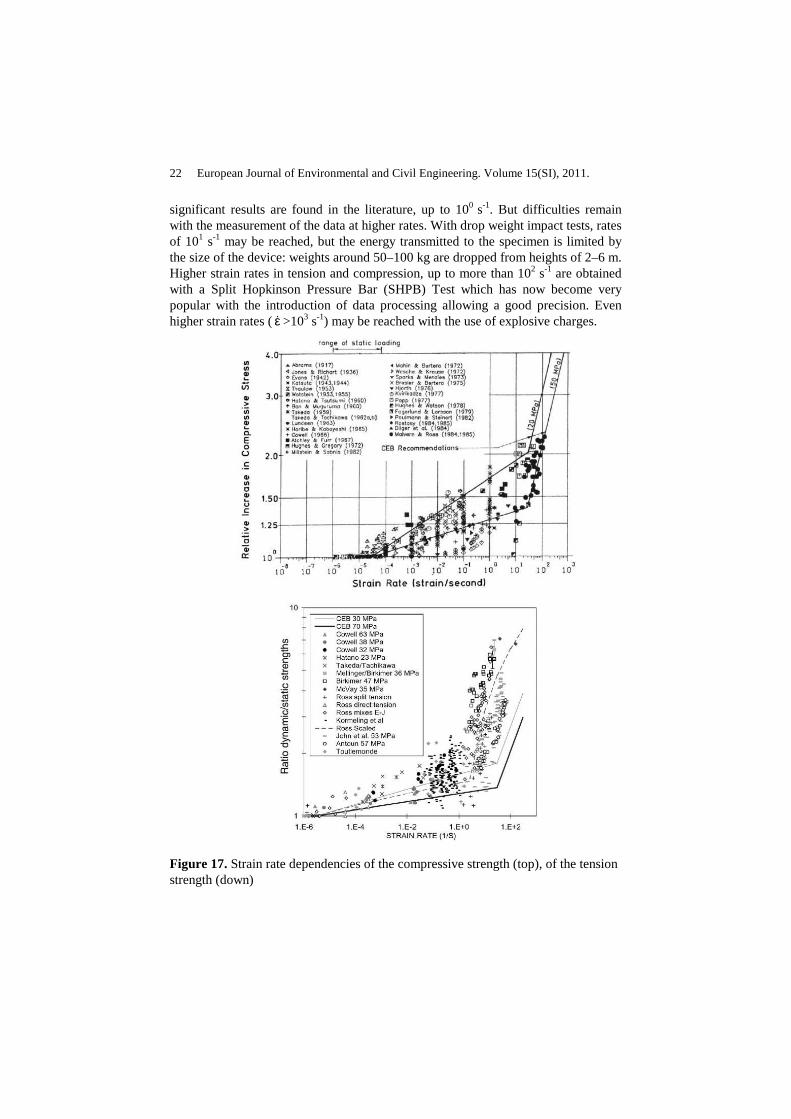
significant results are found in the literature, up to 100 s-1. But difficulties remain with the measurement of the data at higher rates. With drop weight impact tests, rates of 101 s-1 may be reached, but the energy transmitted to the specimen is limited by the size of the device: weights around 50–100 kg are dropped from heights of 2–6 m. Higher strain rates in tension and compression, up to more than 102 s-1 are obtained with a Split Hopkinson Pressure Bar (SHPB) Test which has now become very popular with the introduction of data processing allowing a good precision. Even higher strain rates (ε& >103 s-1) may be reached with the use of explosive charges.
Figure 17. Strain rate dependencies of the compressive strength (top), of the tension strength (down)

Concrete structures under impact 23
The strain rate effect has been studied on different characteristics of concrete: Young’s modulus, Poisson’s ratio, energy-absorption capacity and axial strain at maximum strength are rate-sensitive quantities, but at a much lower intensity than the compressive and tensile strengths (Bischoff and Perry, 1995). Finally, a large part of the results is compiled in Figure 17, in terms of the ratio dynamic strength over static strength. Two distinct types of behaviour can be observed: The first one shows a linear dependence of the ratio with log(ε& ). The second one is a sharp rise in the rate dependence. The limit between the two is around ε& ≈3 101 s-1 in compression and around ε& ≈100 s-1 in tension.
To fully understand the rate effect, it is important to be able to answer the following question: is it a material-intrinsic effect, or rather a structural effect, the state of stress and strain not being homogeneous in the specimen ? To do so, it is necessary to look at some results concerning the influence of different parameters on this ratio: ratio water/cement = W/C, boundary conditions and presence of free water (Bischoff and Perry, 1995; Gopalaratnam et al. 1996; Rossi et al. 1994). It first appears that W/C and boundary conditions are secondary parameters, as they have only a slight influence (nevertheless, it seems that the strain dependence is higher for concretes with lower strengths). Moreover, the ratio dynamic strength over static strength seems to be rather more rate-sensitive in tension than in compression. On the other hand, it now seems clear that the strain rate effect at least when ε& <101 s-1 is explained by the presence of free water in concrete. For higher strain rates, the situation is much less clear: in tension, some insights were proposed by Hild et al. (2003) and in compression, Donzé et al. (1999) and Hentz et al. (2004a) have shown numerically that most of the rate dependency observed in SHPB compressive tests is due to inertia phenomena: in this range of strain rates, the increase of load-carrying capacity of concrete under compression comes from the transition from a state of uniaxial strain to a state of uniaxial stress, associated with bulking; it is a structure effect. These two different conclusions are now discussed.
7.2. Recommendations of CEB
The CEB (Comité Euro-international du Béton, 1988) recommends to take into account rate effects on tensile strength according to the following equations:
>ε
εεθ
≤ε<ε
εε
ε≤ε
=σσ
−
−
13/1
stat
1stat
0168.1
stat
stat
ts
td
s30for
s30for
for1
&&
&
&&&
&
&&
[14]

24 European Journal of Environmental and Civil Engineering. Volume 15(SI), 2011.
Where σtd is the dynamic tensile strength at ε& , σts is the static tensile strength at 16
stat s103 −−=ε& , ε& is the strain rate in the range of 3·10-6 to 300 s-1, σcs is the compressive static strength and σc0 = 10 MPa is a reference value, log(θ) = 7.11δ - 2.33, )/610/(1 0ccs σσ+=δ ,
Similar equations exist for compression. The strain rate effects of various concrete materials were identified from test results shown Figure 17.
According to Hentz et al. (2004a), the strain rate in tension is due to the influence of flaws and a macroscopic modelling of concrete, i.e. with no explicit modelling of these flaws, must account for an expression similar as Eq. [14].
The real material strain rate effect in compression is much less important than observed in tension and the apparent strain rate sensitivity observed on Figure 17 is due to inertia effects. Thus, combining the inertia effect inherent to a 3D analysis in transient dynamics with CEB recommendations (Eq. [14]) may lead to an overestimation of material strength.
In order to assess these assumptions, Hentz et al. (2004a) have modelled Split Hopkinson Pressure Bar (SHPB) tests performed on mortar specimens by means of the Discrete Element Model (DEM) presented in the last section of this paper, some results are presented.
7.3. Rate effect in tension
7.3.1. Probabilistic-deterministic transition involved in the fragmentation process of brittle materials
According to the authors of the present paper, Hild et al. (2003) have given the best explanation of rate effects observed in brittle materials (rocks, concrete, ceramics, glass…).
Brittle materials are characterized by important flaw sensitivity. In 1939 Weibull applied the “weakest link theory” to the interpretation of the variability of fracture stress of nominally identical brittle specimens; the famous probabilistic Weibull model has derived from this analysis. Under quasi-static loading, the use of a probabilistic model for the prediction of brittle material failure is now common, the fragmentation regime corresponds to a single fragmentation (one critical flaw is activated up to failure). Dynamic loadings produce high stress waves leading to the fragmentation of brittle materials. Therefore, depending on the local strain or stress rate, different fragmentation regimes are observed. One regime corresponds to single fragmentation for which a probabilistic approach is needed. Conversely, the multiple fragmentation regime may be described by a deterministic approach as proved by Hild et al. 2003. These authors assumed a random distribution of defects and a damage kinetics. They show that under impact, a stress wave propagates; some defects are activated and propagate whereas some others can not be activated because of the propagation of previously activated defects. There is “obscuration” of some defects (Figure 18). Thus, the weakest link theory does not hold any more, a
Concrete structures under impact 25
multiple fragmentation regime occurs; it may be described by a deterministic approach since it much less depends on the probabilistic distribution of defects.
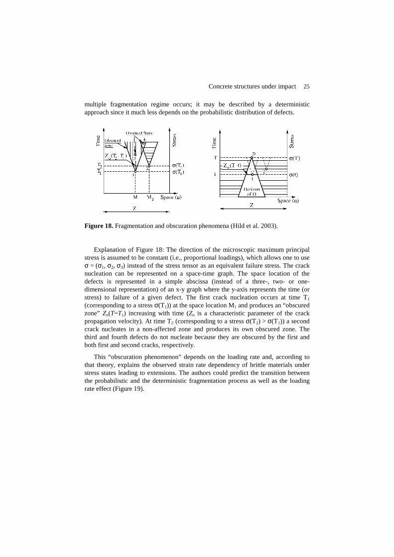
Figure 18. Fragmentation and obscuration phenomena (Hild et al. 2003).
Explanation of Figure 18: The direction of the microscopic maximum principal stress is assumed to be constant (i.e., proportional loadings), which allows one to use σ = (σ1, σ2, σ3) instead of the stress tensor as an equivalent failure stress. The crack nucleation can be represented on a space-time graph. The space location of the defects is represented in a simple abscissa (instead of a three-, two- or one-dimensional representation) of an x-y graph where the y-axis represents the time (or stress) to failure of a given defect. The first crack nucleation occurs at time T1 (corresponding to a stress σ(T1)) at the space location M1 and produces an “obscured zone” Zo(T−T1) increasing with time (Zo is a characteristic parameter of the crack propagation velocity). At time T2 (corresponding to a stress σ(T2) > σ(T1)) a second crack nucleates in a non-affected zone and produces its own obscured zone. The third and fourth defects do not nucleate because they are obscured by the first and both first and second cracks, respectively.
This “obscuration phenomenon” depends on the loading rate and, according to that theory, explains the observed strain rate dependency of brittle materials under stress states leading to extensions. The authors could predict the transition between the probabilistic and the deterministic fragmentation process as well as the loading rate effect (Figure 19).

26 European Journal of Environmental and Civil Engineering. Volume 15(SI), 2011.
Figure 19. Ultimate strength vs. stress rate for a SiC-100 ceramic (from Hild et al. 2003).
7.3.2. Discrete element modelling of tensile tests at high strain rates
Tensile SHPB tests were carried out by Klepaczko and Brara (2001) to explore higher strain rates (20 s-1< ε& <130 s-1) than was available in the literature (Figure 20).Tested concrete has the following quasi-static characteristics: Young’s modulus E = 35 GPa, density ρ = 2350 kgm-3, compressive strength σc = 42 MPa and tensile strength σt = 4 MPa. Constraints listed above led to the following parameters: specimen diameter is equal to 40 mm, its length is 120 mm.
Figure 20. Setup for SHPB experiment in tension.
Hentz et al. (2004a) have simulated two tests at two different rates of loading (36 and 70 s-1). Two series of calculations were carried out for each test: (i) with no rate dependency in the tensile strength between the discrete elements, (ii) with a rate dependency similar to Eq. [14], identified with the test results.

Concrete structures under impact 27
The authors were not able to reproduce the tests with no rate dependency in the tensile strength (i). But, for both tests and by introducing a rate dependency in the tensile strength (ii), they could predict the ejection velocity of fragments as well as the locations of fractures and the number of fragments observed in the two tests.
Figure 21. Discrete element modelling of SHPB tensile tests (Hentz et al. 2004a).
7.4. Rate effect in compression
A SHPB compression tests allows the knowledge of both force and velocity on each face of the specimen. The authors prescribed the velocities and calculated the forces (Figure 22). From these data they could calculate “apparent” axial stress (with the assumption of a specimen in equilibrium) and “apparent” strain rate with Eq. [15] as proceeded with data coming from tests (ls is the specimen length).
Figure 22. Setup for SHPB experiment and boundary conditions (prescribed velocities and measured forces).
s
inputoutputs
s
inputoutput
S2
)t(F)t(F)t(
l
)t(V)t(V)t(
+=σ
−=ε&
[15]
After having identified the rate dependency in tension, Hentz et al. (2004a) have simulated three SHPB tests in compression performed at 350, 500 and 700 s-1 and for the same material by Gary (Zhao and Gary, 1996). As explained before, they
28 European Journal of Environmental and Civil Engineering. Volume 15(SI), 2011.
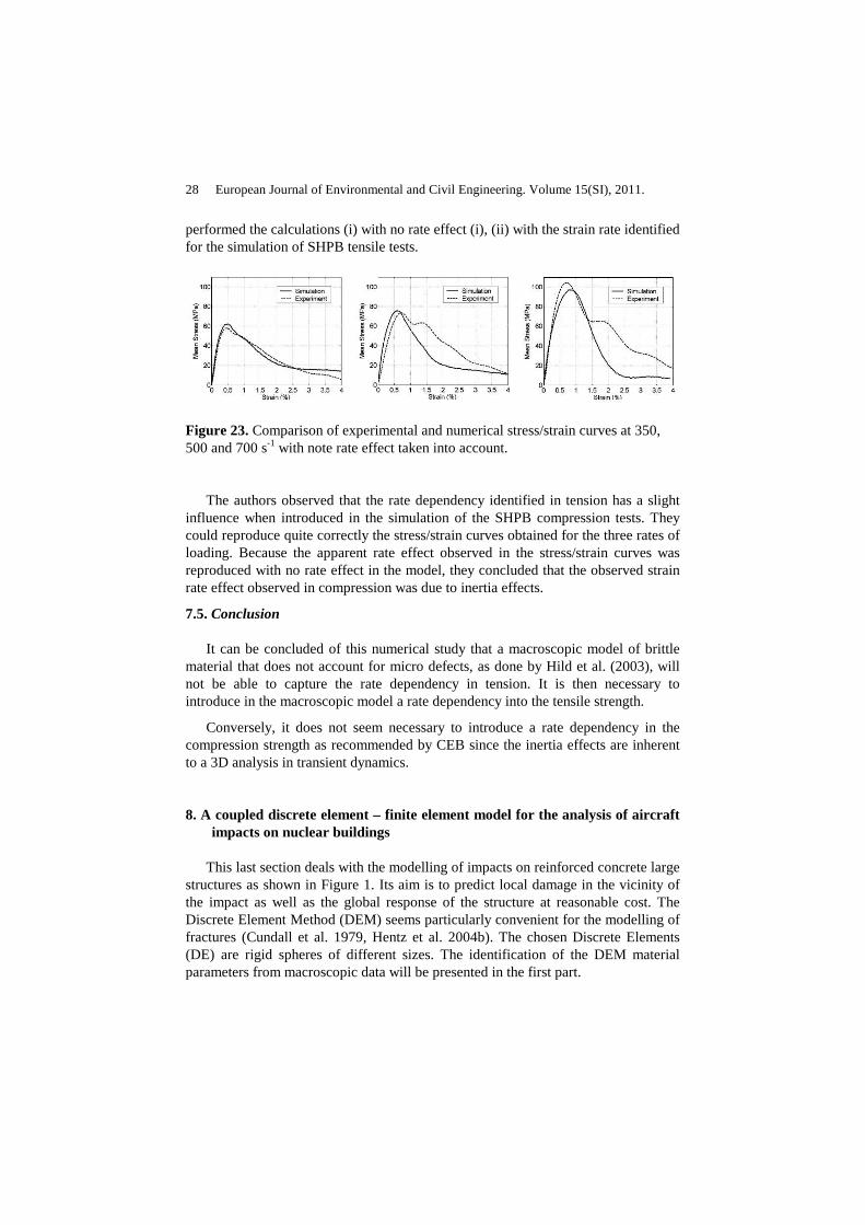
performed the calculations (i) with no rate effect (i), (ii) with the strain rate identified for the simulation of SHPB tensile tests.
Figure 23. Comparison of experimental and numerical stress/strain curves at 350, 500 and 700 s-1 with note rate effect taken into account.
The authors observed that the rate dependency identified in tension has a slight influence when introduced in the simulation of the SHPB compression tests. They could reproduce quite correctly the stress/strain curves obtained for the three rates of loading. Because the apparent rate effect observed in the stress/strain curves was reproduced with no rate effect in the model, they concluded that the observed strain rate effect observed in compression was due to inertia effects.
7.5. Conclusion
It can be concluded of this numerical study that a macroscopic model of brittle material that does not account for micro defects, as done by Hild et al. (2003), will not be able to capture the rate dependency in tension. It is then necessary to introduce in the macroscopic model a rate dependency into the tensile strength.
Conversely, it does not seem necessary to introduce a rate dependency in the compression strength as recommended by CEB since the inertia effects are inherent to a 3D analysis in transient dynamics.
8. A coupled discrete element – finite element model for the analysis of aircraft impacts on nuclear buildings
This last section deals with the modelling of impacts on reinforced concrete large structures as shown in Figure 1. Its aim is to predict local damage in the vicinity of the impact as well as the global response of the structure at reasonable cost. The Discrete Element Method (DEM) seems particularly convenient for the modelling of fractures (Cundall et al. 1979, Hentz et al. 2004b). The chosen Discrete Elements (DE) are rigid spheres of different sizes. The identification of the DEM material parameters from macroscopic data will be presented in the first part.

Concrete structures under impact 29
The modelling of large structures by means of DEM may lead to prohibitive calculation durations because a refined model is required in the vicinity of the impact. In the same time, the structure can be modelled with a coarse finite element (FE) mesh far away from the impact area, because the material behaves elastically. Thus a coupled discrete-finite element approach is proposed: the impact zone is modelled by means of DE and FE are used for the rest of the structure. The proposed approach will be described.
The coupling algorithm has been first developed to couple DEM with 3D Finite Elements (Frangin et al. 2006, Rousseau et al. 2009). Because the shell elements are more widely used to model large thin structures, we propose an adaptation of the coupling procedure to connect Discrete Element model with shell-type Finite Elements. Finally, this coupled approach is applied to calculate the response of a concrete slab impacted by a metallic tubular striker.
8.1. Discrete element model
The fundamentals of the used Discrete Element method are fully described in (Hentz et al. 2004b). The elements are rigid spheres of different sizes. Two types of interactions are defined. The initial interactions between two elements are of a bond-type even if the two elements are not necessarily in contact. During the simulation, additional interactions of contact type can be added. Interactions between two spheres are defined by means of normal Kn and tangential Ks stiffnesses characterizing the elastic behaviour of concrete. "Micro-macro" relations [16] give the local stiffnesses Kn and Ks from the Young's modulus and Poisson's. All details about parameters identification are given in (Rousseau et al. 2008).
[16]
A modified Mohr-Coulomb criterion including both tensile failure and sliding (Eq. [17]) associated with softening is used to model the non-linear behaviour of the material. Local parameters, such as local tensile strength T, cohesion Co and softening factor ξ need to be identified from global parameters such as compressive and tensile strength σc and σt and fracture energy Gf. A classical friction constitutive behaviour is used between elements in contact (Figure 24).
[17]
( ),
1
1 (1 )
1
1
intn a b
init
s n
SK E
D
K K
αβ ν γ αν
ανν
+ = + + −
− = +
1
2
( , ) tan( )
( , )n s s i n int o
n s int n
f F F F F S C
f F F S T F
= − Φ − = −

30 European Journal of Environmental and Civil Engineering. Volume 15(SI), 2011.
Figure 24. DE interaction laws
Figure 25 ,shows the flowchart of the identification procedure allowing to obtain local parameters (local tensile strength T, softening parameter ζ and cohesion Co) using uniaxial and quasi-static tensile and compressive tests (Hentz et al., 2004b). This procedure was applied in order to identify local parameters for a concrete sample extensively studied (Gabet et al. 2006, Vu et al. 2009) and presented in section 6. Results of tensile and compressive tests are shown on Figure 26.
Figure 25. The identification procedure

Concrete structures under impact 31
Figure 26. Identification of the model: Tension (left) and compression (right)
8.2. Coupled model
The coupling procedure between continuum and discrete domains is presented. Discrete element method is convenient for modelling discontinuities and fracture but it may lead to prohibitive costs of calculation for large structures. To optimize the numerical model, we choose to couple discrete elements in the vicinity of the impact with elastic finite elements in the rest of the structure.
Many methods have been already developed for multi-scaled problems Xiao et al. (2004), Ben Dhia et al. (2005) proposed to use a bridging domain where the Hamiltonian is a linear combination of discrete and finite ones. We have chosen to use the bridging domain method to couple DE and FE models. Eq. [18] shows that DE and FE Hamiltonians are weighted by a parameter α whose value is 1 in the FE domain and 0 in the DE domain.
The DE displacements dr are linked in the bridging domain with FE displacements ur [19]. The solution is obtained by minimizing the Hamiltonian with introduction of the kinematic constraints by means of Lagrange multipliers. Details of the method are explained in (Frangin et al. 2006, Rousseau et al. 2009).
H = α HFE + (1 - α) HDE [18]
dr = k ur [19]
For shells, the same coupling method is applied. The problem is to find the appropriate kinematic constraints between shell nodes displacements and discrete elements displacements. Figure 27 shows an example of projection of the DE along the shell normal directions. Tow of four discrete elements cannot be easily located:
32 European Journal of Environmental and Civil Engineering. Volume 15(SI), 2011.
one of them is out of all the two shell elements whereas another one belongs to both shells.
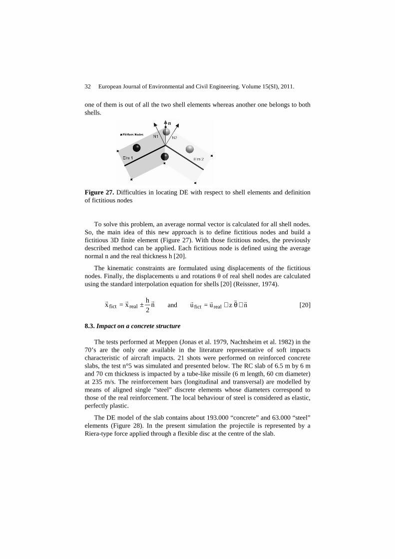
Figure 27. Difficulties in locating DE with respect to shell elements and definition of fictitious nodes
To solve this problem, an average normal vector is calculated for all shell nodes. So, the main idea of this new approach is to define fictitious nodes and build a fictitious 3D finite element (Figure 27). With those fictitious nodes, the previously described method can be applied. Each fictitious node is defined using the average normal n and the real thickness h [20].
The kinematic constraints are formulated using displacements of the fictitious nodes. Finally, the displacements u and rotations θ of real shell nodes are calculated using the standard interpolation equation for shells [20] (Reissner, 1974).
n2
h±x=x realfict
rrr and nzu=u realfict
rrrr∧θ+ [20]
8.3. Impact on a concrete structure
The tests performed at Meppen (Jonas et al. 1979, Nachtsheim et al. 1982) in the 70’s are the only one available in the literature representative of soft impacts characteristic of aircraft impacts. 21 shots were performed on reinforced concrete slabs, the test n°5 was simulated and presented below. The RC slab of 6.5 m by 6 m and 70 cm thickness is impacted by a tube-like missile (6 m length, 60 cm diameter) at 235 m/s. The reinforcement bars (longitudinal and transversal) are modelled by means of aligned single “steel” discrete elements whose diameters correspond to those of the real reinforcement. The local behaviour of steel is considered as elastic, perfectly plastic.
The DE model of the slab contains about 193.000 “concrete” and 63.000 “steel” elements (Figure 28). In the present simulation the projectile is represented by a Riera-type force applied through a flexible disc at the centre of the slab.

Concrete structures under impact 33
Figure 28. DE model of the MEPPEN slab: concrete and loading disc (left), reinforcement (right).
Figure 29. Damage obtained in the RC slab after the test: simulation (left), test (right)
Figure 29 allows a visualization of calculated and experimental damage patterns in the slab. Qualitatively, the results of the numerical simulation are satisfying: one can observe formation of a the typical conical shape of damage corresponding to a particular perforation mode in the form of a conical shear plug delimited by oblique cracks, as observed on the real slab under soft impact.
To quantify the efficiency of this method in terms of calculation times, an “industrial” application is now studied. It consists in a reinforced concrete protection shell loaded by a force representing an aircraft impact. This example is not representative of a real case. The DE zone is located at the top of the building and the load is assumed to be vertical (Figure 30). The loading applied to the DE zone is the same as previously.
The comparison of calculation times given in Table 1 confirms, as expected, the modelling of the non linear constitutive behaviour is expensive (case 1 vs. case 2 and case 2 vs. case 3). Note that the modelling of the whole building by DEM is very expensive justifying the proposed approach. The three calculations give slightly identical results in terms of damage of the top slab modelled by DEM.

34 European Journal of Environmental and Civil Engineering. Volume 15(SI), 2011.
FE shells
DE
Figure 30. Shell FE model coupled with a DE zone at the top
Case 1 Only the DE concrete slab 9 days
Case 2 DE concrete slab + linear shell FE 9 days
Case 3 DE concrete slab + non linear shell FE 20 days
Case 4 Full structure modelled by DE estimated at 360 days
Table 2. Comparison of calculation times
8.4. Conclusion
The proposed approach based on a robust identification procedure and an efficient coupling method opens the way to simulate large reinforced concrete structures under impact.

Concrete structures under impact 35
9. General conclusion
Even if the experimental study and numerical analysis of the response of concrete structures is quite complex and is still an open subject of research, it is important to summarise the main questions discussed in this paper:
a) Impact loads on concrete structures may lead to various rates of loading and levels of damage into the target. Two extreme cases are generally distinguished: the soft impact, for which the target is considered as rigid with reference to the striker, and the hard impact, for which the striker is considered as rigid with reference to the target.
b) Numerous experimental studies were performed in the 70’s and 80’s, mainly by the national nuclear safety agencies, for characterizing the effect of hard impacts (e.g. aircraft engine) or soft impacts (e.g. aircraft fuselage) on concrete barriers.
c) From the previous test results, empirical formulae were proposed for the design of reinforced concrete barriers submitted to hard impacts but their range of validity may be limited and these empirical formulae do not concern new Ultra High Performance Concrete.
A simplified model was proposed for the evaluation of the contact force due to pipe-like impact (e.g. aircraft fuselage). This simplified model was improved by means of experimental results discussed earlier.
d) The constitutive modelling of concrete when submitted to an impact has to reproduce two main features: the behaviour of concrete under high triaxial stress state (including tension) and the behaviour of concrete under high loading rates.
e) Triaxial compression tests performed on ordinary concrete show that the unconfined compressive strength is a poor indicator of the high-pressure mechanical response of concrete. Thus, the validity of empirical penetration formulae has to be considered with caution. These triaxial tests have also shown that the water saturation ratio is an important parameter governing the triaxial compressive strength of concrete.
f) The modelling of high strain rate compression or tension tests performed on concrete specimens by means of Split Hopkinson Pressure Bars (SHPB) shows that the apparent rate effect in compression is due to inertia phenomena in a 3D transient state of stresses. Thus, it is incorrect to affect to the compressive strength a dependency with the strain rate identified with SHPB tests. Conversely, the phenomena are different in tension, concrete behaviour is a brittle material sensitive to micro-defects that are activated or not, depending on the spatial propagation of the loading. Because this loading rate effect depends on micro-defects, a macroscopic modelling of concrete considered as a homogeneous uncracked material must include a loading rate effect.
g) The modelling of impacts on large reinforced concrete structures is still a challenge in terms of complexity and computational costs. A coupled DE/FE method was presented; it allows predicting severe damage such as perforation in the vicinity

36 European Journal of Environmental and Civil Engineering. Volume 15(SI), 2011.
of the impact as well as predicting the global response of the reinforced concrete structure.
10. References
Abbas H., Paul D.K., Godbole P.N. and Nayak G.C., « Reaction-time response of aircraft crash », Computers & Structures, vol. 55, n°5, 1995, p. 809-817
Amirikian A., Design of protective structures. Report NT-3726, 1950, Bureau of Yards and Docks, Department of the US Navy.
Arros J., Doumbalski N., « Analysis of aircraft impact to concrete structures », Nuclear Engineering and Design, vol. 237, n° 12-13, 2007, p. 1241-1249.
Ben Dhia H., Rateau G., « The Arlequin method as a flexible engineering design tool », International Journal of Numerical Methods in Engineering, vol. 62, 2005, p. 1442–1462.
Berriaud C., Dulac J., Sokolovsky A., Labrot R., Gueraud R., Avet-Flancard R., « Local behaviour of reinforced concrete walls under missile impact », Nuclear Engineering and Design, vol. 45, n°2, 1978, p. 457-469.
Berriaud C, Perforation des enceintes en béton par un projectile dur – Rapport de synthèse. Rapport CEA/DMT/93-299, 1993.
Bischoff P.H., Perry S.H., « Compression behaviour of concrete at high strain rates », Materials and structures, vol. 24, n°6, 1991, p. 425-450.
Bischoff P.H., Perry S.H., « Impact behavior of plain concrete loaded in uniaxial compression », Journal of Engineering Mechanics, vol. 121, n°6, 1995, p.685-693.
Buzaud E., Cazaubon C., Chauvel D., « Assessment of empirical formulae for local response of concrete structures to hard projectile impact », Proc. CONSEC 07, Tours, France, 2007, p. 1365-1372.
CEB, « Concrete structures under impact and impulsive loading », Comité Euro-International du Béton, Bulletin d’Information, n°87, 1988, Lausanne, Switzerland.
Cundall P.A., Strack O.D.L., « A discrete numerical model for granular assemblies », Géotechnique, vol. 29, n°1, 1979, p. 47–65.
Donzé F., Magnier S.A., Daudeville L., Mariotti C., Davenne L., « Numerical study of compressive behavior of concrete at high strain rates. Journal of Engineering Mechanics, vol. 125, n°10, 1999, p. 1154-1163.
Dulac J., Giraud J.P., « Impact Testing of Reinforced Concrete Slabs », Proc. 6th SMiRT Conference, Berlin, Germany, 1981, J7/1.
Dupray F, Malecot Y, Daudeville L, Buzaud E, « A mesoscopic model for the behaviour of concrete under high confinement », International Journal for Numerical and Analytical Methods in Geomechanics, vol. 33, n°11, 2009, p. 1407-1423.
Dupray F, Malecot Y, Daudeville L, « Experimental behaviour of high-performance concrete in confined tension », Materials and Structures, vol. 43, n°5, 2010, p. 699-707

Concrete structures under impact 37
Eibl J., « Soft and Hard Impact. Concrete for Hazard Protection », Concrete Society, Edinburgh, UK, 1987, p. 175-186.
Fiquet G., Dacquet S., « Study of the perforation of reinforced concrete slabs by rigid missiles – Experimental study, part II », Nuclear Engineering and Design, vol. 41, n°1, 1977, p. 103-120.
Forrestal M.J., Altman B.S., Cargile J.D., Hanchak S.J., « An empirical equation for penetration depth of ogive-nose projectiles into concrete targets », International Journal of Impact Engineering, vol. 15, n°4, 1994, p. 395–405.
Forrestal M.J., Frew D.J., Hanchak S.J., Brar N.S., « Penetration of grout and concrete targets with ogive-nose steel projectiles », International Journal of Impact Engineering, vol. 18, n°5, 1996, p. 465-476.
Frangin E., Marin P., Daudeville L., « On the use of combined finite/discrete element method for impacted concrete structures », Journal de Physique IV, vol. 134, 2006, p. 461–466.
Fullard K., Baum M.R., P. Barr P., « The assessment of impact nuclear power plant structures in the UK », Nuclear Engineering and Design, vol. 130, n°2, 1991, p. 113-120.
Gabet T, Vu X.H., Malecot Y, Daudeville L., « A new experimental technique for the analysis of concrete under high triaxial loading », Journal de Physique IV, vol. 134, 2006, p. 635-644.
Gabet T, Malecot Y, Daudeville L., « Triaxial behavior of concrete under high stresses: Influence of the loading path on compaction and limit states », Cement and Concrete Research, vol. 38, n°3, 2008, p. 403-412.
Gopalaratnam V., Gerstle W., Isenberg J., Mindess S., State-of-the-art report on dynamic fracture. ACI Committee 446. 1996.
Goldstein S., Berriaud R., Labrot R., « Study of the perforation of reinforced concrete slabs by rigid missiles – experimental study, part III », Nuclear Engineering and Design, vol. 41, n°1, 1977, p. 103-120.
Gran J. K., Frew D. J., « In-target radial stress measurements from penetration experiments into concrete by ogive-nose steel projectiles », International Journal of Impact Engineering, vol. 19, n°8, 1997, p. 715-726.
Grassl P., Jirasek M., « Damage-plastic model for concrete failure », International Journal of Solids and Structures, 43, n°22-23, 2006, p. 7166-7196.
Gueraud R., Sokolovsky A., Kavyrchine M., Astruc M., « Study of the perforation of reinforced concrete slabs by rigid missiles – General introduction and experimental study, part I », Nuclear Engineering and Design, vol. 41, n°1, 1977, p. 91-102.
Haldar A., Hamieh H., « Local effect of solid missiles on concrete structures », ASCE Journal of the Structural Division. vol. 110, n°5, 1984, p. 948-960.
Hentz S., Daudeville L., Donzé F., « Discrete element modelling of concrete submitted to dynamic loading at high strain rates », Computers and Structures, vol. 82, n°29-30, 2004a, p. 2509-2524.

38 European Journal of Environmental and Civil Engineering. Volume 15(SI), 2011.
Hentz S., Daudeville L., Donzé F., « Identification and validation of a discrete element model for concrete », Journal of Engineering Mechanics, vol. 130, n°6, 2004b, p. 709-719.
Jonas W., Meschkat R., Riech H., Rüdiger E., « Experimental investigations to determine the kinetic ultimate bearing capacity of reinforced concrete slabs subject to deformable missiles », Proc. 5th SMiRT, Berlin, Germany, 1979, J8/3.
Jonas W., Rüdiger E., Gries M., Riech H., Rützel H., « Kinetische Grenztragfähigkeit von Stahlbetonplatten », RS 165, Technischer Bericht, Hochtief AG. 1982.
Kang H. D., Willam K. J., « Localization characteristics of triaxial concrete model », Journal of Engineering Mechanics-Asce, vol. 125, 1999, p. 941-950.
Kennedy R.P., « A review of procedures for the analysis and design of concrete structures to resist missile impact effects », Nuclear Engineering and Design, vol. 37, n° 2, 1976, p. 183-203.
Klepaczko J.R, Brara A., « An experimental method for dynamic tensile testing of concrete by spalling », International Journal of Impact Engineering, vol. 25, n°4, 2001, p. 387-409.
Kœchlin P., Potapov S., « Classification of soft and hard impacts—Application to aircraft crash », Nuclear Engineering and Design, vol. 239, n° 4, 2009, p. 613-618.
Kojima I., « An experimental study on local behaviour of reinforced concrete slabs to missile impact », Nuclear Engineering and Design, vol. 130, n°2, 1991, p. 121-132.
Li Q.M., Chen X.W., « Dimensionless formulae for penetration depth of concrete target impacted by a non-deformable projectile », International Journal of Impact Engineering, vol. 28, n°1, 2003, p. 93-116.
Li Q.M., Reid S.R., Wen H.M., Telford A.R., « Local impact effects of hard missiles on concrete targets », International Journal of Impact Engineering, vol. 32, n°1-4, 2005, p. 224-284.
Liu J., Foster S. J., « A three-dimensional finite element model for confined concrete structures », Computers & Structures, vol. 77, n°5, 2000, p. 441-451.
Malecot Y, Daudeville L, Dupray F, Poinard C, Buzaud E, « Strength and damage of concrete under high triaxial loading », European Journal of Environmental and Civil Engineering, vol. 14, n°6-7, 2010, p. 777-803.
Nachtsheim W., Stangenberg F., « Interpretation of results of Meppen slab tests – Comparison with parametric investigations », Nuclear Engineering and Design, vol. 75, n°2, 1982, p. 283-290.
Nachtsheim W., Stangenberg F., « Impact of deformable missiles on reinforced concrete plates – Comparisonal calculations of Meppen tests », Proc. 6th SMiRT, Berlin, Germany, 1981, J7/3.
Ohno T., Uchida T., Matsumoto N., Takahashi Y., « Local damage of reinforced concrete slabs by impact of deformable projectiles », Nuclear Engineering and Design. vol. 138, n°1, 1992, p. 45-52.
Concrete structures under impact 39
Papanikolaou V. K., Kappos A. J., « Confinement-sensitive plasticity constitutive model for concrete in triaxial compression », International Journal of Solids and Structures, vol. 44, n° 21, 2007, p. 7021-7048.
Poinard C, Malecot Y, Daudeville L, « Damage of concrete in a very high stress state: Experimental investigation », Materials and Structures, vol. 43, n°1-2, 2010, p. 15-29.
Reissner E., Linear and nonlinear theory of shells. Thin Shell Structures, Fung and Sechler Eds., Prentice Hall, 1974, 29-44.
Riera J.D., « On the stress analysis of structures subjected to aircraft impact forces », Nuclear Engineering and Design, vol. 8, n° 4, 1968, p. 415-426.
Romander C.M., Sliter G. E., « Model tests of turbine missile impact on reinforced concrete », Nuclear Engineering and Design, vol. 77, n°3, 1984, p. 331-342.
Rossi P., Van Mier J.G.M., Toutlemonde F., Le Maou F., Boulay C., « Effect of loading rate on the strength of concrete subjected to uniaxial tension », Materials and Structures, vol. 27, n°5, 1994, p. 260-264.
Rousseau J., Frangin E., Marin P., Daudeville L., « Damage prediction in the vicinity of an impact on a concrete structure: a combined FEM/DEM approach », Computers and Concrete, vol. 5, n°4, 2008, p. 343- 358.
Rousseau J., Frangin E., Marin P., Daudeville L., « Multidomain finite and discrete elements method for impact analysis of a concrete structure », Engineering Structures, vol. 31, n°11, 2009, p. 2735-2743.
Rüdiger E., Riech H., « Experimental and theoretical investigations on the impact of deformable missiles onto reinforced concrete slabs », Proc. 7th SMiRT, Chicago, USA, 1983, J8/3.
Sugano T., Tsubota H., Kasai Y., Koshika N., Itoh C., Shirai K., Von Risemann W.A., Bickel D.C., Parks M.B., « Full-scale aircraft impact test for evaluation of impact force », Nuclear Engineering and Design, vol. 140, n°3, 1993, p. 373-385.
Sugano T., Tsubota H., Kasai Y., Koshika N., Itoh C., Shirai K., Von Risemann W.A., Bickel D.C., Parks M.B., « Local damage to reinforced concrete structures caused by impact of aircraft engine missiles – Part 2. Evaluation of test results, Nuclear Engineering and Design, vol. 140, n°3, 1993, p. 407-423.
Sugano T., Tsubota H., Kasai Y., Koshika N., Ohnuma H., Von Risemann W.A., Bickel D.C., Parks M.B., « Local damage to reinforced concrete structures caused by impact of aircraft engine missiles – Part 1. Test program, method and results », Nuclear Engineering and Design, vol. 140, n°3, 1993, p. 387-405.
Vu X.H., Malecot Y, Daudeville L, Buzaud E., « Experimental analysis of concrete behavior under high confinement: Effect of the saturation ratio », International Journal of Solids and Structures, vol. 46, n°5, 2009a, p. 1105-1120.
Vu X.H., Malecot Y, Daudeville L., « Strain measurements on porous concrete samples for triaxial compression and extension tests under very high confinement », Journal of Strain Analysis for Engineering Design, vol. 44, n°8, 2009b, p. 633-657.

40 European Journal of Environmental and Civil Engineering. Volume 15(SI), 2011.
Vu X.H., Malecot Y, Daudeville L, Buzaud E, « Effect of the water/cement ratio on concrete behavior under extreme loading », International Journal for Numerical and Analytical Methods in Geomechanics, vol. 33, n°17, 2009c, p. 1867-1888.
Walter T.A., Wolde-Tinsae A.M., « Turbine missile perforation of reinforced concrete », Journal of Structural Engineering, vol. 110, n°10, 1984, p. 2439-2455.
Xiao S., Belytschko T., « A bridging domain method for coupling continua with molecular dynamics », Computer Methods in Applied Mechanics and Engineering, vol. 193, 2004, p. 1645-1669.
Zhao H., Gary G., « On the use of SHPB techniques to determine the dynamic behavior of materials in the range of small strains», International Journal of Solids and Structures, vol. 33, n°23, 1996, p. 3363–3375.