Embed Size (px)
Citation preview

032-
1704
-121
e-06
a
A4Tekst start
AALBORG WHITE®
Concrete HardeningAugust 2006

AALBORG WHITE®
Concrete Hardening
COWI A/S Parallelvej 2 DK-2800 Kongens Lyngby Denmark Tel +45 45 97 22 11 Fax +45 45 97 22 12 www.cowi.dk
Table of Contents 1 Introduction 1 2 Conclusion 2 3 General concrete hardening problems due to
hydration heat 2 3.1 Internal restraint 2 3.2 External restraint 3 3.3 Maximum temperature 3 4 The State-of-the-art situation 4 4.1 Temperature requirements 4 4.2 Stress requirement 4 4.3 Measures to reduce thermal stresses 5 5 Comparisons between white and grey concretes 5 5.1 Internal restraint 8 5.2 External restraint 9 5.3 Maximum temperature 11 5.4 The influence of shrinkage 11 6 References 13 7 Appendix 14
1 Introduction The white concrete is attractive aesthetically. As white concrete also has a higher compressive strength potential than the grey concrete, this adds new per-spectives to the use of white concrete.
White cement develops considerately more heat during hydration than tradi-tional grey cement. This could lead to a conclusion that there is a higher risk for cracks developing when white concrete is used compared to when grey con-crete is used. Calculations however indicate that this is not the case, maybe on the contrary. The present note describes considerations regarding thermal cracking and presents results from thermal and stress simulations supporting the above statements.
Document no. P-54631-A-4
Issue no. 0
Date of issue 15-08-2006
P:\54631A\PDOC\Hærdeberegninger\HEJ0007059_rev0.DOC
Prepared HEJ
Checked BBU
Approved BBU

Concrete Hardening 2 / 14
2 Conclusion
White cement concrete develops more heat during hydration and hence in-duces higher temperatures differences during hardening than the grey cement concrete.
The investigated white concrete can however endure larger temperature differ-ence than the grey reference concrete.
This means that the risk of cracks forming during hydration is comparable for white and grey concrete, respectively
As demonstrated in this memo using only temperature requirements in planning against cracks forming are misleading for grey as well as for white concrete
The use of white cement concrete would - as is often also the situation for grey concrete - require documentation for the hardening requirements (crack control) depending on the geographical traditions in relation to crack and temperature control.
3 General concrete hardening problems due to hydration heat
During hardening concrete develops heat due to the hydration of the cement.
Under adiabatic and unrestrained conditions the concrete will expand as a result of the heat development. During this condition without interaction to the sur-rounding environment the concrete is in a state without internal stresses.
In a real construction situation a cast concrete will however loose heat to the surroundings and the cast concrete will often be joined to other previously cast structural elements. Stresses are therefore generated.
3.1 Internal restraint During hardening the concrete temperature will raise. Loosing heat to the sur-roundings will result in a temperature difference between the surface (cold) and the core (warm) of the concrete. Due to the coefficient of expansion and the temperature difference, internal stresses will occur. The stresses will develop following the development of the stiffness (E-modulus) of the concrete; the higher stiffness the higher stress. This situation is defined as internal restraint.
A colder surface results in tensile stresses developing in the surface of the sec-tion and compression in the core. As long as the tensile stresses in the surface do not exceed the tensile strength of the concrete, no cracking will take place.
P:\54631A\PDOC\Hærdeberegninger\HEJ0007059_rev0.DOC .

Concrete Hardening 3 / 14
When the cast concrete has reached thermal equilibrium with the surrounding environment the stresses will disappear.
If the tensile stresses generated in the surface exceed the tensile strength of the concrete cracks will form. As the core is in compression the cracks will only become surface cracks. When thermal equilibrium is reached the core contracts too and the surface cracks will be closed.
3.2 External restraint The increase in temperature will cause the entire cast section to expand. If the casting is joined to a previously cast structure, the expansion will be restrained by the joining structure as the joining structure is in or closer to a thermal equi-librium with the surroundings than the newly cast structure. This restraint will cause tensile stresses in the older structure and compressive stresses in the newly cast concrete structure. During expansion the new concrete is "soft" as the E-modulus is not yet fully developed and the compressive stresses will be small.
When the new concrete cools to thermal equilibrium it contracts. The concrete has now become stiffer due to the continuously development of the E-modulus. The tensile stresses developed during contraction are larger than the stresses developed during the expansion. The final state will be tensile stresses in the newly cast concrete and compressive stresses in the joining structure. These stresses are permanent stresses and they reach maximum when the new con-crete is in thermal equilibrium with the surroundings.
If the permanent tensile stresses exceed the tensile strength of the concrete then permanent cracks will develop. These cracks will form through the entire cross-section.
3.3 Maximum temperature Massive bulk structures can experience maximum hardening temperatures ex-ceeding 70 0C. Hardening temperatures above approx. this level can result in a future risk of delayed ettringite formation. The ettringite formation depends not only on temperature but also on the composition of the cement. Tests can be carried out to document a specific cement behaviour upon hardening at high temperatures.
While the temperature problems in relation to internal and external restraint are relative problems, the maximum temperature reached in a concrete structure depends not only on the heat development, but also the casting concrete tem-perature and the ambient temperature.
P:\54631A\PDOC\Hærdeberegninger\HEJ0007059_rev0.DOC .

Concrete Hardening 4 / 14
4 The State-of-the-art situation The problems related to internal restraint, external restraint and maximum tem-perature are traditionally dealt with by means of average temperature require-ments based on experience or finite element computer simulations.
4.1 Temperature requirements It is common practice that one would expect no problems in relation to internal restraint as long as the difference between the average sectional temperature and the minimum concrete temperature (typically the surface temperature) does not exceed 15 0C.
For external restraint it is generally recommended (e.g. in Danish Code DS 411) that the temperature difference between the average temperatures of the newly and previous cast structures does not exceed 15 0C in order not to cause problems.
The two temperature requirements and the maximum temperature can be calcu-lated before casting based on information of the adiabatic heat development of the concrete. Measurements on site are performed to document that the re-quirements are met. In this situation the stress situation is unknown.
4.2 Stress requirement Some specifications, typically for larger infrastructure projects, require that the stresses are calculated in order to demonstrate that a planned hardening regime effectively reduces the stresses and hence the risk of cracking to a sufficiently low level.
To be able to calculate the stresses the following concrete parameters as a func-tion of the concrete maturity are required:
• Structural geometry
• Adiabatic heat development
• Tensile strength development
• E-modulus development
• Shrinkage
• Creep
Other input parameters, e.g. poisons ratio are required to perform a realistic cal-culation, but these can be found in the literature.
Shrinkage is a contraction of the concrete. In relation to internal stresses the structure can not distinguish between thermally induced contraction or shrink-
P:\54631A\PDOC\Hærdeberegninger\HEJ0007059_rev0.DOC .

Concrete Hardening 5 / 14
age induced contraction. Furthermore the structure cannot distinguish between autogeneous, chemical and drying shrinkage.
Creep is a time-dependent deformation induced by stresses. Creep reduces the internal stresses and for that reason it is important to include creep to achieve a realistic simulation of the hardening stresses.
4.3 Measures to reduce thermal stresses There are a number of measures to take into consideration in order to reduce stresses induced by heat development e.g.
• Cooling pipes embedded in the concrete
• Heat wires in the older structure
• Chilled fresh concrete e.g. by Nitrogen or ice
• The choice of formwork e.g. steel vs. wood. Insulation using mats or sheets etc.
• Time between two castings (reduction will reduce temperature differ-ence and hence stresses formed)
By these measures the temperature difference due to heat development can be reduced or theoretically removed.
Assuming that the temperature difference is reduced to zero, shrinkage still in-troduces stresses. While the temperature difference contributes to the stresses within the first 2-7 day, shrinkage will contribute to the stresses for decades, relieved only by creep.
From a structural point of view there is no difference whether a structure cracks within a week or within a year. A crack is a crack and it is impossible to distin-guish between a crack induced by primary heat development or shrinkage. In both cases the crack can have a detrimental effect on the overall durability of the structure.
5 Comparisons between white and grey concretes Aalborg Portland has conducted various tests on different mixes using low-alkali-sulphate-resistant as well as Aalborg White Portland cement. The test results are presented in [1] and the mix compositions shown in Table 1.
In the following, the results of investigations using a reference grey concrete (Ref. A) compared to a batch using Aalborg White (mix B1) cement has been investigated in relation to temperature development, stress induction and meas-ures to reduce thermal stresses. The Ref. A concrete is a high performance con-
P:\54631A\PDOC\Hærdeberegninger\HEJ0007059_rev0.DOC .

Concrete Hardening 6 / 14
crete similar to the concrete used on The Great Belt Bridge. The cement used for Ref. A is a low heat cement. The input parameters are reported in [1].
Ref. A Mix B1 Aalborg White cement kg/m3 371 Low-alkali sulphate cement kg/m3 312 Microsilica kg/m3 20 20 Fly ash kg/m3 59 - Zinc Stearate kg/m3 w/p-ratio - 0.36 Table 1 Mix-design of the binder phase of the concretes investigated. Further information about aggregate and additives used can be found in [1].
In the calculations below a beam (or wall) cast against an existing slab is con-sidered. Temperature and stresses have been estimated using a finite element (FEM) analysis using the program 4CTemp & Stress [2], ref. Appendix.
In Figure 1 a principal sketch of the structure considered is shown, together with the physical assumptions for the calculations.
wall shutter existing slab
Assumptions: Dimensions on wall: b = 0.2; 0.4; 0.6 and 1.0 m h = 3 m Casting temperature: 18°C Temperature for existing concrete slab: 20°C Temperature air: 20°C Shutter material: 19 mm plywood with thermal conductivity 20 kJ/m2/h/°C 1 m
Figure 1. Principal sketch of the structure used for calculations
The calculations are based on an assumed casting temperature of 18 0C and en-vironmental temperature of 20 0C.
P:\54631A\PDOC\Hærdeberegninger\HEJ0007059_rev0.DOC .

Concrete Hardening 7 / 14
The following definitions are used when evaluating the test results:
The utilization ratio in the following is defined as the ratio between tensile stresses and tensile strength. A utilization ratio larger than 1 means that the tensile stress is larger than the tensile strength, and theoretically the concrete will crack. The utilization ratio combines the influence of shrinkage, heat development, the development of the E-modules and the subsequent stresses and the devel-opment of tensile strength into one parameter, which tells whether the concrete cracks or not.
Geometrical restraint ratio is in the following defined as the ratio between the cross section of the new and the old structure.
The white concrete Mix B1 is compared to the reference concrete (Ref.A) at different wall thickness and form stripping time. Hereby the risk of crack in-duction can be assessed, among other as a result of internal restraint and exter-nal restraint. Calculations for different wall thickness and geometrical restraint ratios have been conducted as shown in Table 2. Results are given in Appendix.
The thicker the wall the less heat can leave the structure and as a consequence the temperature rise is larger for thicker walls than for thinner walls. The con-clusion of the present investigations is that the thickness of the casting has the same effect for white concretes as for grey concretes. This means that that the white concrete showed no different behaviour than the grey in relation to the utilization ratio. A wall thickness of 400 mm corresponds to the in practise most common struc-tural size in relation to the behaviour investigated.
P:\54631A\PDOC\Hærdeberegninger\HEJ0007059_rev0.DOC .

Concrete Hardening 8 / 14
Calculation no. Mix no. Geometrical restraint ratio 3)
Wall thickness (mm)
a_200 Ref. A 6.67 200 a_400 Ref. A 3.33 400
b1_400 Mix B1 3.33 400 a_600 Ref. A 2.22 600
b1_600 Mix B1 2.22 600 a_1000 Ref. A 1.33 1000
b1_1000 Mix B1 1.33 1000 a_400s Ref. A 0.4 400
b1_400s Mix B1 0.4 400 a_400_cooled 1) Ref. A 3.33 400
b1_400_cooled 1) Mix B1 3.33 400 a_400_no_heat 2) Ref. A 3.33 400 b1_400_no_heat2) Mix B1 3.33 400 1) Contains 6 nos. of Ø20 mm cooling pipes with 150C cooling water. 2) No heat development only shrinkage. 3) Ratio between cross section of new and old structure, ref. Figure 1 Table 2. Survey of calculations conducted. Results are given in Appendix
5.1 Internal restraint Stripping the formwork after 32 hours will cause utilization-ratio of 1.10 for the grey concrete (Ref. A) and 1.05 for the white (Mix B1). In this situation there is no practical difference between the two concretes concerning stresses. The tem-perature difference between the average and the minimum temperature is 190C for the grey and 250C for the white. It is noted that both the temperature differ-ence and the utilization ratio indicate that there is a risk that cracks may de-velop in both the grey and the white mix.
Stripping the formwork after 72 hours will cause a temperature difference of 150C for both concretes as common practice would allow as maximum tem-perature difference. At that stripping time the utilization ratio is 0.5 and 0.4 for the grey and the white concrete, respectively, hence no risk of cracks forming.
The above findings are presented in Figure 2. Figure 2 indicates that the maxi-mum temperature difference resulting in internal restraint cracking (utilization ratio exceeding 1) is 180C for the grey concrete (Ref. A) and 240C for the white (Mix B1).
P:\54631A\PDOC\Hærdeberegninger\HEJ0007059_rev0.DOC .

Concrete Hardening 9 / 14
The internal restraint for concrete mixes using white cement is not higher than for traditional grey concretes. The amount of internal restraint has to be investigated each time for both grey and white concretes if a realistic evalua-tion of crack formation is required.
The investigated white concrete can endure larger temperature difference than the grey reference concrete.
15
19
15
25
0
0.2
0.4
0.6
0.8
1
1.2
10 15 20 25 30
Temperature difference (Deg. C)
Util
izat
ion
ratio
Ref. A (Grey)B1 (White)
Figure 2 Utilization ratio vs. temperature difference for concretes based on grey and white cement, respectively.
5.2 External restraint Comparing Ref. A concrete and Mix B1 concrete for different wall thicknesses in relation to external restraint it is found that the external restraint results in approximately the same utilization ratio for both the white (Mix B1) and the grey concrete. However the white concrete develops a maximum utilization ratio faster than the grey concrete, but 28 days after casting the ratio is ap-proximately the same. This is illustrated in Figure 3.
In the case where the maximum utilization ratio is 1.7, the white concrete ex-ceeds a utilization ratio of 1.0 (crack criterion) after 50 hours while the grey concrete exceeds the utilization ratio of 1.0 after 139 hours. The maximum tem-perature difference is 220C for the grey and 340C for the white concrete. This situation is related to a geometrical restraint ratio (the ratio between the cross section of the new and the old structure) of 3.3. Reducing the geometrical re-straint ratio to 0.4 will result in a reduced utilization ratio from 1.7 to 0.7. The
P:\54631A\PDOC\Hærdeberegninger\HEJ0007059_rev0.DOC .

Concrete Hardening 10 / 14
maximum temperature difference for the white and grey concretes, respectively remains the same.
Despite the significantly higher temperature of the white concrete there is no impact on the utilization ratio (stress/strength ratio), compared to that devel-oped in the grey concrete. In other words that there is not a higher risk of cracks forming for the white concrete than the grey concrete despite the higher tem-perature.
The stress/strength development is illustrated in figure 3. The abbreviations are:
• a_400: Ref. A (grey) concrete. Wall thickness 400 mm and geometrical restraint ratio 3.33
• b1_400: White concrete, Mix B1. Wall thickness 400 mm and geomet-rical restraint ratio 3.33
• a_400_s: Ref. A (grey) concrete. Wall thickness 400 mm and geomet-rical restraint ratio 0.4
• b1_400_s: White concrete, Mix B1. Wall thickness 400 mm and geo-metrical restraint ratio 0.4
50 139
0.0
0.2
0.4
0.6
0.8
1.0
1.2
1.4
1.6
1.8
2.0
30 130 230 330 430 530 630Time (h)
Stre
ss/s
tren
gth
ratio
a_400 b1_400 a_400s b1_400s
Figure 3. Stress/strength ratio vs. time of grey and white cement concrete walls, thickness 400 mm, at geometrical restraint ratios 0.4 and 3.33 respectively. The external restraint for concrete mixes using white cement is not higher than for traditional grey concretes. The amount of external restraint has to be investigated each time for both grey and white concretes if a realistic evalua-tion is required.
The investigated white concrete can endure larger temperature difference than the grey reference concrete.
P:\54631A\PDOC\Hærdeberegninger\HEJ0007059_rev0.DOC .
Concrete Hardening 11 / 14
5.3 Maximum temperature Under adiabatic conditions the grey concrete will reach a maximum tempera-ture of 680C while the white (Mix B1) concrete will reach 780C, when the cast-ing temperature is 180C. Adiabatic conditions are only prevailing in bulk mas-sive concrete structures.
Casting at 180C and for ambient temperatures of 200C the grey concrete will reach a maximum temperature of 560C while the white will reach 700C for a wall thickness of 1000 mm.
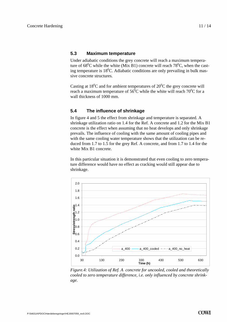
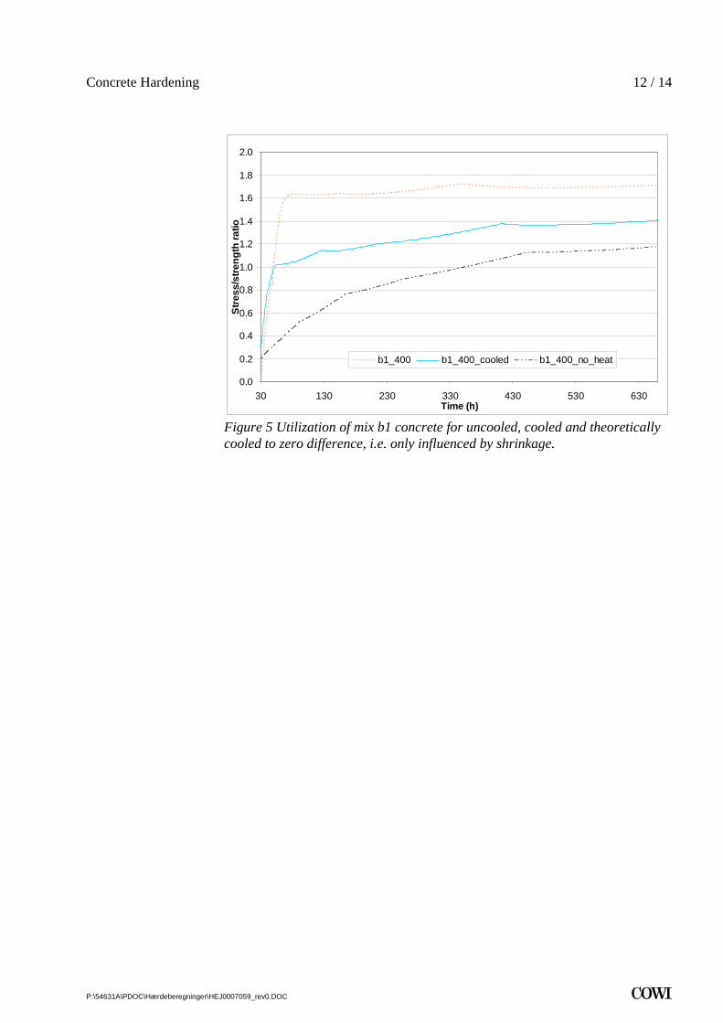
5.4 The influence of shrinkage In figure 4 and 5 the effect from shrinkage and temperature is separated. A shrinkage utilization ratio on 1.4 for the Ref. A concrete and 1.2 for the Mix B1 concrete is the effect when assuming that no heat develops and only shrinkage prevails. The influence of cooling with the same amount of cooling pipes and with the same cooling water temperature shows that the utilization can be re-duced from 1.7 to 1.5 for the grey Ref. A concrete, and from 1.7 to 1.4 for the white Mix B1 concrete.
In this particular situation it is demonstrated that even cooling to zero tempera-ture difference would have no effect as cracking would still appear due to shrinkage.
0.0
0.2
0.4
0.6
0.8
1.0
1.2
1.4
1.6
1.8
2.0
30 130 230 330 430 530 630Time (h)
Stre
ss/s
treng
th ra
tio
a_400 a_400_cooled a_400_no_heat
Figure.4: Utilization of Ref. A concrete for uncooled, cooled and theoretically cooled to zero temperature difference, i.e. only influenced by concrete shrink-age.
P:\54631A\PDOC\Hærdeberegninger\HEJ0007059_rev0.DOC .
Concrete Hardening 12 / 14
0.0
0.2
0.4
0.6
0.8
1.0
1.2
1.4
1.6
1.8
2.0
30 130 230 330 430 530 630Time (h)
Stre
ss/s
treng
th ra
tio
b1_400 b1_400_cooled b1_400_no_heat
Figure 5 Utilization of mix b1 concrete for uncooled, cooled and theoretically cooled to zero difference, i.e. only influenced by shrinkage.
P:\54631A\PDOC\Hærdeberegninger\HEJ0007059_rev0.DOC .

Concrete Hardening 13 / 14
6 References [1] . "White Concrete for Aggressive Environment" Aalborg White®; Aalborg Portland; September 2003
[2] 4CTemp&Stress
P:\54631A\PDOC\Hærdeberegninger\HEJ0007059_rev0.DOC .

Concrete Hardening 14 / 14
7 Appendix Selected calculation results
P:\54631A\PDOC\Hærdeberegninger\HEJ0007059_rev0.DOC .


![Untitled-2 [] Industries.pdfI Floor Screeds, Cement Base OR Concrete Surface Hardening Compound OR Dry Shake Hardener 125 KgsBag I Most ideal for de-watering concrete flooring systems](https://img.dokumen.tips/doc/110x75/5f13e13d20d9973c315d6ed2/untitled-2-industriespdf-i-floor-screeds-cement-base-or-concrete-surface-hardening.jpg)