Embed Size (px)
Citation preview

/--LEGAL N O T I C E
. t
V
I
Contract No a W-7405-eng-26
REACTOR DIVISION
CONCEF”U& SYSTEM DESIGN DESCRIPTION of the
SALT PUMP TEST STANI) for the
Molten Salt Breeder Drperiment
A. G . Grindell C. K, McGlothlan
AUGUST 1969
OAK RIDGE NATIONAL LABORATORY Oak Ridge, Tennessee
Operated by UNION CARBIDE CORPORATION
for the U . S . ATOMIC EPJERGY COMMISSIOrJ
ORNL -TM- 26 43


iii
Contents
.
-.
V
List of Figures ................................................. List of Tables .................................................. List of Contributors ............................................ Abstract ........................................................ 1.0 Introduction ...............................................
1.1 System Function ....................................... 1.2 Summary Description of the System .....................
1.2.1 Salt Circulating System ........................ 1.2.2 Heat Removal System ............................ 1.2.3 Utility Systems ................................ 1.2.4 Instrumentation and Controls ................... 1.2.5 Safety Features ................................
1.3 System Design Requirements ............................ 1.3.1 Function ....................................... 1.3.2 Pump Size ...................................... 1.3.3 Allowable Stress for Ni-Mo-Cr Alloy ............ 1.3.4 Instrumentation and Controls ................... 1.3.5 Engineered Safety Features ..................... 1.3.6 Control of Effluents ........................... 1.3.7 Quality Standards and Assurance ................ 1.3.8 Test Stand Parameters .......................... 1.3.9 Thermal Transients ............................. 1.3.10 Codes and Standards ............................
2.0 Detailed Description of System ............................. 2-1 Test Section .......................................... 2.2 Salt System ...........................................
2.2.1 Function ....................................... 2.2.2 Description ....................................
2.2.2.2 Salt Storage Tank and Transfer Line ... 2.2.2.3 Salt Selection ........................ 2.2.2.4 Material for Construction .............
2.2.2.1 Salt Piping ...........................
Page
vii
viii
ix
.
X
1
1
5 5 6 6 6 7 7 7 7 8 8 8 9 9 9 10
11
11
11 12
12
12
12
14 15 1.5

i v
2.2.2.5 Elec t r i c Heaters ...................... 2.3 Heat Removal System ...................................
2.3.1 Function ....................................... 2.3.2 Description ....................................
2.3.2.1 Heat Exchangers ....................... 2.3.2.2 Blowers ...............................
2.4 U t i l i t y Systems ....................................... 2.4.1 I n e r t Gas ...................................... 2.4.2 Instrument A i r ................................. 2.4.3 E l e c t r i c a l .....................................
2.4.3.1 2400 Volt System ...................... 2.4.3.2 480/240/120 Volt System ...............
2.5 S i t e Location ......................................... 2.6 Instrumentation and Controls ..........................
2.6.1 Temperature Measurement and Control ............
2.6.3 Flow Measurement ...............................
2.6.5 Alarms and In te r locks ..........................
2.6.2 Pressure Measurement and Control ...............
2.6.4 Level Measurement ..............................
2.6.6 Data Acquisit ion Computer System ............... 3.0 Pr inc ip les of Operation ....................................
3.1 Sta r tup ............................................... 3.2 Test Operation ........................................
3.2.1 Prototype Pump ................................. 3.2.2 ETU and MSBE Pumps .............................
3.3 Shutdown .............................................. 3.4 Specia l or Infrequent Operation .......................
4.0 Saf tey Precautions .........................................
4.2 Incor rec t Operating Procedure .........................
3.5 Equipment Safety ......................................
4.1 Lost of Normal E l e c t r i c a l Power .......................
4.3 Leak o r Rupture i n S a l t Containing Piping and Equipment .............................................
Page . 1.5 18 18 18 18 21
22
22
22
22
22
23
23 25 25
25 26 26 26 27 28 28 29 29 30 30 31- 31 33 33 33
34
.

V
Page
5.0 Maintenance ................................................. 35 5 .1 Maintenance Philosophy ................................. 35 5.2 Freventive Maintenance ................................. 35
6.0 Standards and Quality Assurance ............................. 36 6.1 Codes and Standards .................................... 36
6.1.2 Materials ....................................... 36
6 . l L . 4 Operations ...................................... 36
6.1.1 Design .......................................... 36
6,1.3 Fabrication and Installation .................... 36
6 # 2 Quality Assurance ...................................... 37 6.3 Quality Assurance Program .............................. 37 6.4 Qdality Assurance Organization ......................... 39
6.5.1 Fabrication and Assembly Work Plan .............. 39 6.5.2 Quality Assurance Program Plan .................. 39 6.5.3 Evaluation of Updating of Plans ................. 40
6.6 Quality Assurarice Requirements ......................... 40 6,6.1 Document Understanding .......................... 40 6.6 -2 Document Control ................................ 41
6.5 Quality Assurance Planning ............................. 39
6.6.3 Records ......................................... 41 6.6.4 Audit ........................................... 42
6.7 Quality Control Requiyements ........................... 42 6.7.1 Off-Site Inspection *ocedures .................. 42
6.7.3 Interface Control ............................... 43 6.7.2 Nonconformance Control .......................... 43
6.7.4 Inspection and Test Equipment ................... 43 6.7.5 Special Precautions ............................. 43 6.7.6 Corrective Action and Feedback .................. 44
6.7.7 Procedures Relating to System Operation ......... 44 APPENDICES
A Applicable Specifications, Standards, and Other Publications ........................................... 46
B Pipe Line Schedule ..................................... 48

Vi
C
D
Page - Valve List ............................................. 50 Instrument and Piping Schematic Diagram ................ 51
Y
W

v i i
Figure
1
2
3
4
5
6
7
L i s t of Figures
Pump Test Stand, Elevation V i e w
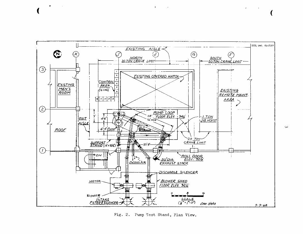
Pump Test Stand, Plan V i e w
MSBE Primary S a l t Pump, Conceptual Configuration
Pump Test Stand S a l t Piping, Pressure P r o f i l e
Pump T e s t Stand, Typical Section of Heat Ekehanger
Pump Test Stand, S i t e Location
Qua l i ty Assurance Program Organization
Page
2
3
4
1 3
20
24
-
3 8

vili.
List of Tables
Table
1 MSBE Pump Design Requirements
2 MSBE Reactor Design Parameters Pertinent to Salt Pumps
3 Salt Pump Test Stand Design Requirements
4 Composition and Properties of Tentative MSBE Primary Salt
5 Composition and Properties of Tentative MSBE Secondary Salt
6 Composition and Properties of Ni-Cr-Mo Alloy
7 Parameters and Variables f o r Pump Test Stand Heat Removal System
8 Data for Main Blowers, Heat Removal System
9 Alarms, Emergencies, and Safety Actions for Salt Pump Test Stand
Page
8
9
10
16
16
-
17
19
21
32
I

ix
L i s t of Contributors
The Oak Ridge National Laboratory cont r ibu tors t o t h i s r epor t i n -
clude :
A. H. Anderson
A. G . Grindel l
R. F. Hyland
R. E. MacPherson
C. K. McGlothlan
H. J. Metz
P. G. Smith
R. D. S t u l t i n g

Ab s t rac t J
A s t a d LE required t o t e s t t h e salt pumps f o r the Molten S a l t
Breeder Experimect (%BE) . It w i l l be designed t c x c o m s d e t e pumps
having capac i t ies ranging from 3000 t o 7000 gpm and operat ing with
salt cf s p e c i f i c g r a v i t i e s t o 3.5 ai, discharge pressures t o 400 ps ig
and temperatures t o 1300°F norrrally and t o 1400°F f o r sho r t periods
cf t i m e .
system f o r t h e loop w i l l be designed for 1500 hp.
t o pro tec t personnel and equipmefit I'rom t h e de l e t e r ious e f f e c t s of a
salt l eak w i l l be taken.
Both t h e dr ive motor e l e c x i c a l supply and t h e hea t removal
Preventive measures
Tne primary end secondary salt pumps f o r t h e MSBE w i l l be operated
i n the s tand using a deplete6 uranium, na tu ra l l i t h ium f luo r ide salt t o
simulate t h e MSBE p r i m r y s a l t . A prototype sal t pump, procured from
the U . S . p u p i n d m t r y , w i l l be subJected a t representa t ive operat ing
c m d i t i o n s t o perfornance and endurmce t e s t i n g of i t s hydraul ic ,
mechanical, and e l e c t r i c a l desigz f ea tu res . ??le EISBE sa l t pump ro ta ry
elernents w i l l bc scbJc:%c& tz k z t shakedowr, t e s t i n g i n t h c stand t o pro-
vide f i n a l confirmation of performa;.ce p r i e r t o i n s t a l l a t i o n i n t h e re -
ac to r systern. The Xencn-rexovai de7rice afid rrolten sa l t instrumentat ion
t o fleasure pressare , flow, L i q u i C l eve l , c t c . w i l l be tes ted a t design
conditions I n molten selt as they becoze ava i lab le , and t h e s tand w i l l
be aodi f ied , as reqklred, t o s2corlxodzte these t e s t s .
The conceptual desigr, of t k e t es t s tand Fs presented. The descr ip-
t i o n , funct ion, arid design requirenimts f o r componen5s and subsystems
are provided. Ti?e p r inc ip l e s of operat ioa of t h e t e s t s tand and t h e
sa fe ty precautions are discussed. %e xaintenance philosophy i s de-
scri'ced and t n e q u a l i t j assurance pi-ogrm i s oukl ined.
Keywords: pump, molten sal t p?mp, high temperature pump, pump testo
s tand, component developnent, molter1 sal t r eac to r , nuclear r eac to r ,
prototype pump, primary szl t p u ~ p ~ coolant s a l t pump.

1.0 Introduction
1.1 Svstem Function
V
Reliable salt pumps are necessary to the satisfactory operation of the Molten Salt Breeder Experiment (MSBE), and efforts to obtain them
will include operating the salt pump with molten salt in a test stand
to prove performance and endurance characteristics.
The salt pump test stand, shown schematically in Figs. 1 and 2, will be utilized to provide design evaluation and endurance testing in molten
salt at essentially isothermal test conditions of a prototype primary
fuel salt pump for the MSBE and to prooftest the primary and secondary
salt pumps for the Engineering Test Unit (Em) and the MSBE. The salt
circulating system will be designed to contain the maximum pump discharge
pressure of 400 psig at 1300°F and for short periods of time at 1400°F. The salt flow can be varied from 3000 to 7000 gpm. ‘his document dis-
cusses the salt pump test stand.
Figure 3 presents a practical configuration for the MSBE primary
salt pump. We presently envision that the hydraulic designs of the
primary and secondary salt pumps will be very similar if not idectical.
The similarities in thermal transport properties of the two salts and in the hydraulic requirements of the primary and secondary salt systems
support this approach. The use of similar hydraulic designs permits
the developmental testing of both salt pumps in this single test stand with one test salt. The salt pumps, described briefly in Sect. 2.1,
Test Section, will be obtained from the United States pump industry and
installed into the test stand in sequence.
of these pumps, and their drive motors and auxiliary equipment, are not
parts of this salt pump test stand activity, but all these activities will be coordinated.
The design and procurement
The primary salt pump is expected to be located at the reactor core
outlet in the MSBE and thus will operate in the highest temperature salt, approximately 1300°F, in the primary salt system. The secondary salt
p m p will be located at the outlet of the intermediate heat exchanger and thus will operate in the highest temperature salt, approximately i150°F,

2
1
t .
3
V
t
I I
I

4
A ORNL DWG. 69-8558
4. '.
' A ,
. -MOTOR
/ M O T O R CWTAINMENT Y€SSEL
-COUPLING
PEN€ TR ATtON
II
UPPER SHAFT SEAL
BEARING #OUS/NG
L O d € R SHAFT SERL
NUCLEAR SHIELD PLUG
CON TANM&N T
SALT LEVEL
PUMP TANK
Fig. 3 . MSBE Primary Salt Pump, Conceptual Configuration.

5
v
W
in the secondary salt system. m e primary salt pump tank will be located
in an oven, which will enclose the primary system, and portions of the
pump w i l l be subjected to a high ambient temperature, estimated to be
1100°F. In addition, it will be subjected to intense nuclear radiation
from components in the primary system, the circulating fuel in the pump
tank, and from gas-borne fission products in the pump tank gas space.
The prototype MSBE primary salt pump will be operated in the test
stand in molten salt over the full range of MSBE conditions of tempera-
ture, pressure, flow, and speed to prove the mechanical, structural, End
hydraulic designs of the pump and to provide cavitation inception char- acteristics at design and off-design operating conditions. However, no
attempt will be made to simulate all features of the high-temperature
oven or to impose nuclear radiation on components in the test stand.
Rotary elements of the primary and secondary salt pumps of the E 2 U
and the MSBE will be subjected to a high temperature, non-nuclear proof- test in the test stand in molten salt prior to installation into their respective systems. At other times the stand will be used to subject
the prototype pump to endurance operation in molten salt. It is impor- tant to the economy of the MSBE program to demonstrate that the pump has
the capability for uninterrupted operation in molten salt f o r periods of
one year and longer. Subsequently, the stand w i l l be used to study un-
anticipated problems that may arise during the operation of the ETU add the MSBE. The proposed test program is discussed in Sect. 3.2.
1.2 Summarv DescriDtion of the Svstem
1.2.1 Salt Circulating System
Figure 1 presents the approximate configurational relationship of
the principal components of the test stand. The stand will be located
in Building 9201-3, Y-12 Area of Oak Ridge Operations. The salt circulating system consists of the circulating pump (test
section), a throttling valve, two salt-to-air heat exchangers, and the connecting piping.
from the pump discharge to the pump suctioll.
vided to contain the quantity of salt necessary to fill the circulating
It provides a closed piping loop for the molten salt
A salt storage tank is pro-
r
b
system.
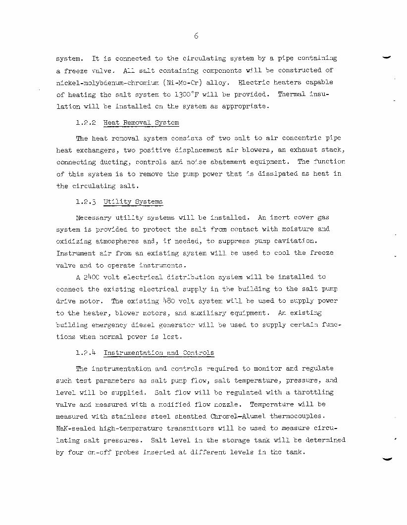
a f reeze vslve. AlL s< containing components w i l l be constructed of
nickel-molybdenum-chromium (Ni-Mo-Cr) a l loy . E l e c t r i c hea te r s capable
of heat ing t h e sal t system t o i3OO"F w i i i be provided.
l a t i o n w i l l be i n s t a l l e d on t h e system as appropriate .
It i s connected t o t h e c i r cu la t ing system by a pipe containing
Thermal insu-
1.2.2 Heat Removal System
The hea t removal system consis1;s of two sal t t o a i r concentr ic pipe
hea t exchangers, two pos i t i ve displacement a i r blowers, an exhaust s tack,
connecting ducting, cont ro ls and noise abatement equipment. The funct ion
of t h i s system i s t o remove the pump power t h a t i s d i s s ipa t ed as hea t i n
%he c i r cu la t ing sa l t .
1 .2 .3 U t i l i t y Systems
Necessary u t i l i t y systems w i l l be i n s t a l l e d . An i n e r t cover gas
system i s provided t o p ro tec t t h e sal t from contact with moisture and
oxidizing atmospheres and, i f needed, t o suppress pump cav i t a t ion .
Instrument a i r from an ex i s t ing system w i l l be used t o cool t h e freeze
valve and t o operate in s t ruqen t s .
A 2400 v o l t e l e c t r i c a l d i s t r i b d t i o n system w i l l be i n s t a l l e d t o
comec t t h e e x i s t i n g e l e c t r i c a l supply i n t h e bui ld ing t o t h e sal t pump
dr ive motor. The e x i s t i n g 480 v o l t system w i l l be used t o supply power
t o t h e hea ter , blower motors, and a u x i l i a r y equipment. An ex i s t ing
bui ld ing emergency d i e s e l generator w i l l be used t o supply c e r t a i n func-
t- ions when normal power i s l o s t .
1 .2 .4 Instrumentation and Controls
I
The ins t runenta t ion and contro1.s required t o monitor and regula te
such tes t p a r m e t e r s as sal t p u ~ p flow, sal t temperature, pressure, and
l e v e l w i l l be suppl ied.
valve and measured with a xodi f ied flow nozzle. Temperature will be
measured with s t a i n l e s s s t ee l sheatked Chromel-Alumel thermocouples.
NaK-sealed high-temperature t ransmit . ters w i l l be used t o measure c i rcu-
l a t i n g sal t pressures .
by four on-off probes in se r t ed a t d i f f e r e n t l e v e l s i n t h e tank.
S a l t flow w i l l be regula ted with a t h r o t t l i n g
S a l t l e v e l i n t h e s torage tank w i l l be determined

7
An existing Beckman DEXTIR data acquisition system will be used to
log the more important salt temperatures and pressures and the pump salt
flow, power, and speed.
Other test stand temperatures and pressures will be monitored and
controlled with conventional equipment.
1.2.5 Safety Features
The test stand will be enclosed in a sheetmetal structure which will
cover the top and sides and will have pans to catch salt spills and leaks.
The enclosure will be provided with a ventilation system.
1.3 System DesigE Requirements
Criteria have been established to obtain a test stand that will pro-
vide maximum performance and endurance information for the MSBE salt pumps
in a safe and economical manner. The criteria include:
1.3.1 Function
The pump test stand will be designed to (1) accommodate full-size
salt pumps for the MSBE primary or secondary systems, (2) provide a non- nuclear test environment, and (3) yield performance and endurance data to assure maximum capability and reliability of the pumps in the MSBE.
1.3.2 Pump Size
The design of the test stand is centered on the pump sizes required for a 200 Mw(t) MSBE, as shown in Table 1. cations, it will be capable of accommodating pumps ranging in flow
capacity fron 50% smaller to 50% larger than the MSBE pumps.
removal, salt flow, and electric power capabilities will be oversized
to provide this flexibility. Adequate structural allowances will also
be provided to obtain this flexibility.
However, with minor modifi-
The heat

8
Table 1. MSBE Pump Design Requirements
Cover
Pressure ODE r a t i n g Pumping Motor Gas
Head Eff ic iency Size rn Flow
(gpm) ( f t ) (%) lemp . ( OF) (hp) ( p s i g )
1300 5 7 0 ~ 150 80 1000 -50
Secondary S a l t Pump 1150 7000 300 80 900 -150
Primary S a l t Pump
*Includes 500 gpm bypass flow through gas separa tor .
1.3.3
The allowable design stress for. high temperature operat ion of t h e
Allowable S t r e s s f o r Ni-Mo-Cr Alloy
a l l o y w i l l be based on t h e creep rate c r i t e r i o n , 0.1% elongat ion i n
10,000 h r , a t t h e design temperature. See Table 6.
1.3.4 Instrumentation and Controls
Instrumentation end cont ro ls w i l l be provided t o monitor t e s t s tand
cperat ion, t o maintain t e s t parameters within prescr ibed ranges, and t o
obta in required p m p t e s t da ta .
which safe operat ion of t h e t e s t s t m d can be maintained.
A cont ro l area w i l l be provided from
I. 3 e 5
Engineered sa fe ty features w L L be provided.
Engineered Safe ty Fea tmes - A s a minimum, they
w i l l be designed t o cope with any s i z e pressGre boundary break, up $0
and including t h e c i rcumferent ia l r'iipture of any pipe i n %he t e s t s tand
with unobstructed discharge f r o x both ends.
An independent emergency power system will be provided, designed
with adequate capaci ty and t e s t a b i l l t y t o insure t h e funct ioning of a l l
engineered sa fe ty f ez tu res . The containment design b a s i s i:; t o contain t h e pressure and tempera-
ture r e s u l t i n g from the l a r g e s t c red ib le elzergy release following an
accident without exceeding the design sal t vapor leakage ra te . Appropri-
a t e features vi11 be provided t o p rc t ec t personcel i n case of an acciden-
t a l rupture .

9
1.3.6 Control of Effluents
The design of the test stand will provide the means necessary to
maintain control over toxic and radioactive effluents, whether gaseous,
liquid, or solid, to protect personnel. The low level radioactivity is
associated with z3eU and 232Th components in the test salt.
will be maintained during normal operation and accident conditions to
preclude the release of unsafe amounts of these effluents.
Control
1.3.7 Quality Standards and Assurance
A quality assurance program will be written and implemented to en- hance the certainty of achieving the pump test operation objectives.
Systems and components that are essential to prevent accidents that
could affect personnel safety or to mitigate their consequences will be
identified and designed, fabricated, and erected to quality standards
that reflect their safety importance.
or standards on design, materials, fabrication, and inspection are used, they will be identified. Where adherence to such codes or standards
does not assure a quality level necessary to the safety function, they
will be supplemented or modified, as necessary.
Where generally recognized codes
1.3.8 Test Stand Parameters
Table 2 presents the MSBE design parameters which affect salt pump
The principal hydraulic and thermal design requirements for design. the sal t pumps, based on these MSBE design parameters, have been shown
in Table 1.
stand, as deduced from the MSBE requirements, are shown in Table 3. The principal design requirements for the salt pump test
Table 2. MSBE Reactor Design Parameters Pertinent to Salt Pumps
Reactor size, Mw(t) 200 Quantity of primary salt pumps, ea 1 Quantityof secondary salt pumps, ea 1
250 Secondary salt circuit AT, "F 300 Reactor pressure drop (estimated), ps i 34 Heat exchanger pressure drop (estimated), psi 1-35
Primary salt circuit AT, "F

Table 3. S a l t Pmp Test Stand Design Requirements
S a l t
Heat
-P
piping
Operating temperature
Operating tempere5ur-e ( m a x i m u m )
Pressure See Fig. 4
1 3 0 0 ' ~ f o r 5 years
1400'F f o r 1000 h r
Primary s d t flow, gpm 3000-7000
removal c a p a b i l i t y ( m a x i m u m ) 1.12 Mw
motor capaci ty (maximum) 1500 hp
1.3.9 Thermal Transients
The t e s t s tand has a l imi ted c a p a b i l i t y f o r performing thermal
t r a n s i e n t t e s t s .
t he pump of 8 t o 10°F per ninute for a 20 ninute period can be obtained
u t i l i z i n g maxirrum s d t system cooling and reducing p u ~ p speed t o give
approximately lO$ design flow.
ta ined &iring c p e r a t i z i a t desig;n p ~ r p speed with the sal t cooling sys-
tem o f f .
A cooling t r a n s i e n t i n t h e salt c i r c u l a t i n g through
A s i m i l a r heat ing t r a n s i e n t can be ob-
A l a rge cooling thermal shock e l s o can be appl ied t o the pump i n
the t e s t loop as follows: with the pmp motor stopped, t he temperature
Gf t h e pump inipeller and casing and sal t i n the pmp tank can, for i:istsr,ce, 52 ncin%ained et approximately 1300"~, while the sal t i n t he
icsp pipEng i; i3wered t o z k o A 1990°F.
~p t o design speed wlthin 2 t o 3 seconds, acd the c o d sal t from t h e
piping would displace the hot salt i n the f u l l y loaded pump impeller
and casing.
Tile salt pump would be brought
Prellmicary ana lys i s of t he YEBE systems i nd ica t e s t h a t t he p lan t
can be designed t o operste without I-arge fast temperature t r a n s i e n t s .
If analysis of t t e d e t a i l e d design x d i c a t e s t h a t t r a n s i e n t s outs ide
the c a p a b i l i t y of the t e s t s tand a r e l i k e l y to be experienced, t h e t e s t
s tand can be modified.
t h e ternperatwe of the c i r c u l a t i n g sal t through the pump by mixing with
a s t r e m of sa l t a t a s c b s t a n t i a l l y d i f f e r e n t temper8ture.
Additional equipmen? would be provided t o change

11
L 1.3.10 Codes and Standards
Section 6 .O outlines the codes, standards, specifications, procedures, reviews and inspections, and the quality assurance program that will be
used to design, construct, and operate the test stand. The design of the
salt containing system will be based on Section 111, Nuclear Vessels, for
Class C Vessels of the ASME Boiler and Pressure Vessel Code and on the
Pressure Piping Code, USAS B3l.l. Approved RDT Standards will be used for all systems and subsystems as applicable and available.
2.0 Detailed Description of System
The test stand consists principally of piping, a pump heat removal
system, utility systems, and instrumentation and controls which are
described below.
of the stand are described in Section 4. The salt pump is described also. The safety featues
2.1 Test Section
The test section w i l l consist of a salt pump with its drive motor
and controls and the auxiliary lubricating and cooling systems.
conceptual configuration, Fig. 3, the salt pump is a vertical, single stage, centrifugal sump pump with an in-line electric drive motor. This
vertical pump configuration has been used satisfactorily to pump molten salt in many component test stands, the Aircraft Reactor Ecperiment (ARE),
and the MSRE. It is expected that the MSBE pumps will have a similar configuration and will be larger in size. The primary salt pump will be
designed for service with highly radioactive, high temperature, fission-
able and fertile, molten salt. The secondary salt pump will be designed
for service at high temperature with a molten heat transfer salt. The
tentative design conditions for the MSBE primary and secondary salt pumps are given in Table 1.
In the
The design and procurement of the salt pumps and associated variable
speed drive motors are not part of this pump test stand activity.
procurement from the U. S . pump industry is directed and funded in
another portion of the MSBE program.
Their
This procurement activity will be

12
c lose ly coordinated with t h e design, f ak r i ca t ion , and operat ion of t he
t e s t s tand.
2.2 S a l t System
2.2.1 Function
The sal t c i r cu la t ing system provides a closed piping loop f o r t h e
molten salt from t h e pump discharge t o t h e pump suc t ion .
s t o r e sal t while t h e pump i s inoperat ive and equipment t o t r a n s f e r sa l t
between t h e s torage tank and t h e c i r cu la t ing system w i l l be provided.
A tank t o
2.2.2 Description
2.2.2.1 S a l t Piping. The pumped sa l t leaves t h e discharge nozzle
of t h e pump and en te r s t he piping which contains f ixed r e s t r i c t o r s t o
simulate t h e pressure drop i n t h e MSBE primary hea t exchanger (FR-1)
and the r eac to r ves se l (FR-2), and a var i ab le r e s t r i c t o r ( t h r o t t l i n g
valve, HCV 100) .
t he Schematic Diagram, Appendix D . )
s t r i c t o r s , two concentr ic pipe sal t - to -a i r heat exchangers (HX-1 and 2 ) ,
a flow s t r a igh tene r , a nozzle f o r measuring flow, and a simulated r eac to r
o u t l e t before re turn ing t o the p u p a t t h e suc t ion nozzle.
(Component designat ions, e .g., FR-1, are presented i n
The sal t passes through these re-
The p r e s s u e l e v e l s i n t h e sal$ c i r c u l a t i n g system are es tab l i shed
by t n e head developed by t h e sal t pimp and t h e cover gas pressure required
to suppress cav i t a t ion i n t h e p u ~ p . 2 e l a t i v e l y s m a l l f r i c t i o n pressure
drops w i l l occur i n t h e sal t flow-measuring nozzle and t h e piping loop,
and r e l a t i v e l y l a r g e p r e s s w e drops i n t h e sa l t t h r o t t l i n g valve and t h e
f ixed r e s t r i c t o r s . The piping pressure p r o f i l e f o r t h r e e primary sal t
flow rates i s given ill Fig. 4. The t h r o t t l i n g valve i s used t o vary salt
flows from 3000 t o 7000 gprn, t h e latf,er flow rate at t h e wide-open pos i t ion .
The sal t pump w i l l be operated from t h e high t o t h e low l i m i t s of flow
t o obtain pump d a t a a t design and off-design condi t ions.
I.@, o r 500 gpm, of t he primary pump design flow of 5700 gpm i s bypassed
through a gas s t r i p p e r and gas i n j e c t o r system and returned t o t h e pump
suct ion. This flow does not t r ave r se t h e main sal t c i r c u l a t i n g system.
Approximately
A pipe d iaqe ter of 12 i n . w a s s e l ec t ed f o r t h e c i r c u l a t i n g salt loop W
as t h e r e s u l t of s tud ie s requi r ing (1) a spec i f i ed m a x i m u n salt v e l o c i t y

13
ORNL DWG. G-8559
r- L- SALT FLOW -
7000 GPM
I I---,
5200 4PM I \ \
I
L -- ------y- 3000 GPJ
-PIPING TRAVERSE -
Fig. 4. Pump Test Stand Salt Piping, Pressure Profile.

i n t he pipe of 30 f t / s e c , ( 2 ) minimization of sa l t inventory, and ( 3 ) s a t i s f a c t o r y heat t r m c f e r . i n t h e s a l t - t o - a i r heat removal system. The
design pressure f o r t he piping i s 200 psig. A sho r t sec t ion of 10-in.-
diam pipe, containing the flow r e s t r i c t o r (FR-i) which siniuiates the p r i -
mary heat exchanger, connects t he pimp discharge t o the t h r o t t l i n g valve.
The design pressure f o r t h i s s e c t i o n of piping i s 340 ps ig which w i l l
accommodate pressures up t o 400 ps ig f o r sho r t periods of t i m e . Location
of t h i s f ixed r e s t r i c t o r and t h r o t t i i n g valve c lose t o t h e pump discharge
provides a lower pressure downstream of t h e valve t o permit t h e use of
th inner w a l l pipe f o r tl?e major port,ion of t h e sa l t piping.
s t r e s s ana lys i s i nd ica t e s t h a t t h e w a l l th ickness of 0.500 i n . f o r t he
10-in. pipe and 0.375 i n . f o r t he 12-in. pipe w i l l be adequate.
A preliminary
Tne t h r o t t l i n g valve w i l l be a manually operated valve very similar
t o one t h a t w a s developed severa l years ago f o r molten sal t use a t Oak
Fidge National Laboratory (ORNL).
i s present ly i n use i n a molten sal t t e s t s tand at ORNL, and it has been
operated more than 40,030 h r .
t o 25,009 h r .
1-0 i n . ) f o r use i n the t e s t s tand. The design pressure of 300 ps ig f o r
t he - alve body w i l l be based on t h e allowable s t r e s s values f o r long term
crzep, Sect ion 1.3.3, however, t h i s pressure can s a f e l y be exceeded f o r
s h o r t periods of time t o obtain t h e required range of pump head vs flow
data D
One of these valves ( 3 1 /2 in. in size)
Four o+,her valves have operated from 10,000
Tois vaive design w i l l be “scaled up” i n s i z e (probably t o
P02*2.2 S a l t Storage Tank 2nd Trsnsfer Line. The salt s torage tank
w i l l be designed t o contain the q m n t i t y of sa l t required t o f i l l t h e
pump tank, a l l t he piping i n t h e c i r c u l a t i n g system, and t h e t r a n s f e r
l i n e . Tke salt i n the tank can be In l i q u i d o r s o l i d form. The tank
w i l l be equipped with e l e c t r i c hea te rs capable of heat ing t h e tank and
contents t o 1200’F. The tank, which i s t e n t a t i v e l y s i z e d 4 f t i n diam
5y 12 1/2 f t long, w i l l contain the estimated system sa l t volume of
100 cu f t and provide f o r a gas space, t h e thermally expanded salt , and
a h e e l i n the tank. A preliminary ana lys i s i nd ica t e s t h a t f o r a design
texperature Gf 1200°F and design pressure of 75 psig, a tank w a l l th ick-
ness of 3/8 iz. w i l l s u f f i c e .
The sal t t r a n s f e r l i n e connecting the salt s torage tank t o t h e c i r -
cu la t ing sal t piping loop w i l l be 1 1/2 i n . sched 40 piping.
a i r -cooled f reeze valve, i d e n t i c a l t o f reeze valves used i n the MSRE,
w i l l be used t o e s t a b l i s h a plug of s o l i d sal t i n the dra in l i n e and thus
maintain the appropriate salt inventory i n the sal t piping. Auxiliary
heating w i l l be applied, when required, t o melt t he frozen sal t plug and
permit molten sal t t o flow through the t r a n s f e r l i n e from the sal t piping
i n t o the s torage tank.
A 1 1/2-in.
Based on experience a t the MSRE, it i s estimated t h a t t he f reeze
valve can be frozen or thawed i n less than 15 minutes, and the piping
loop can be drained by gravi ty i n 45 t o 70 minutes.
2.2.2.3 S a l t Select ion. Present ly , t he hydraul ic designs f o r t he
primary and secondary sal t pu~mp a r e p r a c t i c a l l y iden t i ca l ; therefore ,
it i s planned t o operate the r o t a r y elements of both t h e primary and
coolant sa l t pumps i n the t e s t s tand using a s ing le sal t i d e n t i c a l t o
t h e r e a c t o r primary ( f u e l ) sa l t , except t h a t depleted 238U ins tead of
enriched 235U and na tu ra l l i th ium ins tead of l i thium-7 w i l l be used.
The cos t of t h e t e s t sal t i s s i g n i f i c a n t l y l e s s than t h a t of t he r e a c t o r
primary salt , and t h e chemical and physical p roper t ies of both salts a r e
i d e n t i c a l .
Chemical composition and physical p roper t ies of t he pr inary sal t
and secondary salts a r e given i n Tables 4 and 5 . 2.2.2.4 Material for Construction. The m a t e r i a l chosen for t h e
sa l t -conta in ing piping and a l l sa l t wetted p a r t s i s t h e Ni-Cr-Mo a l l o y
used t o construct t h e salt system i n t h e MSRE and s e l e c t e d for t h e MSBE.
The composition and proper t ies of t h i s a l loy are given i n Table 6.
2.2.2.5 E l e c t r i c Heaters. E lec t r i c hea te rs , capable of heat ing
a l l sa l t -conta in ing piping and equipment t o 1200"F, w i l l be provided.
The hea ters w i l l be 230 v tubular type, and ceramic hea ters , i n which
the heat ing element i s t o t a l l y enclosed i n ceramic.
hea te rs w i l l be derated by applying a m a x i m u m of 140 v. In general , t he
Manually operated var iab le vol tage c i r c u i t s w i l l be provided f o r
cont ro l of the hea ter power.
of each h e a t e r c i r c u i t .
Amme+,ers w i l l be provided f o r supervision
Operatiol: of t he hea ters w i l l be monitored by

Table 4. Composition and Properties of Tentative MSBE Primary Salt
Density :
Viscosity:
Salt Mole % LiF 71.7 BeF2 16
- Composition :
ThF, 12
m4 0.3 a(lb/ft3) = 235.11 - 0.02328 t ( OF) 204.9 lb/ft3 at 1300°F 210.7 lb/ft3 at 1050°F
n( centipoisej = 0.080 exp 4340/T ( OK) +25% 16.4 lb/ft/hr at 1300°F, 34.18 lb/ft/hr at 1050°F
Heat Capacity : Tnermal Conductivity:
0.324 Btu/lb O F , -1r0.006
0.58 to 0.75 Btu/hr "F ft
Melting Point: 930 "F
Table 5. Composition and Properties of Tentative MSBE Secondary Salt
Composition: Salt
Density :
NaBF4 NaF
Mole $ 92 8
116 lb/ft" at 1050°F (centipoise) = 0.04 exp 3OOO/T ( OK), +SO%
11.4 lb/ft/hr at 1050 "F Viscosity:
Hest Capacity: 0.360 Btu/lb OF, ?2$ Thermal Conductivity:
Melting Point: 725 "F
0.289 Btu/hr/ft OF, -Ir50%
V

Table 6. Composition and Properties of Ni-Cr-Mo Alloy"
Chemical Properties:
Ni 66 -71% Mn, rnax
Mo 15 -18 Si, max
Cr 6-8 Cu, m a x
Fe, m a x 5 B, m a x
C 0.04-0.08 W, max
Ti + A l , rnax 0.50 P, max
S, max 0.02 Co, max
Physical Properties:
Density, lb/ir~.~
Melting Point, "F Thermal conductivity, Btu/hr-ft2 - "F/ft at 1300°F Modulus of elasticity at -1300°F, psi
Specific heat, Btu/lb-"F at 1300°F
Mean coefficient of thermal expansion, 70-1300°F range, in./in.-"F
Mechanical Properties: b Maximum allowable stress, ps i : at 1000°F
1100 "F 1200 "F
1300 OF
1 .o% 1.0
0.35 0.010
0.50
0.015
0.20
0.317
2470-2555 12.7
24.8 x 10⁶
0.135
8.0 x
17, ooo 13,000 6,000
3,500
a Commercially available as "Hastelloy N" from Haynes Stellite Company, and from International Nickel Company, and All Vac Metals Company.
bASME Boiler and Pressure Vessel Code, Case 1315-3.

temperatures o’ctair;ed from thermocozples mounted on the surface of all
heated conpocerrLs.
2.3 Xeat Rern~val S y s t e n
2.3 .1 Puction
The power s:;pplied by the pump to the circulating salt is dissipated
in heating the salt.
move this heat from the circulattng salt, and thus prevent the salt piping
from reaching excessively high temperatures.
The function of the heat removal system is to re-
2 3.2 Description
Without heat removal the anticlpated pumping power of 1000 hp for
the primary salt pump would raise the temperature of the approximately
100 ft3 of circulating salt nearly 6’F per minute. an open cycle system designed to remove 3.82 X lo6 Btu/hr, that is, to accommodate 1530 hp pm-ping power.
A study was made of
Several different heat removal systems were investigated to provide
a tolerable ncise levz1, reasonable physical size, safety, economical
and sixrle construction and operation, and minimum maintenance. Systems
investigated included (1) thermal convectLon salt-to-air radiator, (2)
foxed circulatioz salt-tc-2ir radiator, (3) salt-to-steam heat exchanger, azd (k ) salt-to-ciir heat exchenger with and without water mist. sustz31e heat ri.zov;l, netbod z-d rht. m e sdopted consists of two conce~?-
Tric 3ir cool izg Jackets moixted one on enc‘n of two straight pipe runs
in the loop and supplied with air 5y positive displacement blowers.
(See FLg. 1 aizu the Schenatic Di%grD, Appendix D e )
The most
2.3.2.5 Heat Exchangers. TLb2-e 7 presents important parameters and resxlts of the study of tke sal:;-to-air eoncentric pipe heat ex-
changers,
air is in the concentric annuiar flow passage. A typical cross section
through the heat exchanger is shown in Fig. 5. Two separate, identical heat exchangers (.3X-S and -2) are used to reduce the size of the air
b l G w e r s and the resulting noise level, simplify heat exchanger design,
and provide flexikility in the operation of the test stand.
‘he salt is in the 12-h- pipe (OD 12.75 in.) and the blown

Table 7. Parameters and Variables f o r Pump Test Stand Heat Removal System
The following parameters were used i n t h e heat removal study:
Pump capaci ty , gpm
Pump head, f t
Design hea t load, hp
A i r i n l e t temperature, OF A i r o u t l e t temperature, O F
Log mean AT, OF S a l t pipe OD
Total air flow, scfm
S a l t temperature, "F
5200
15 0 1500 hp = 3.82 x lo6 Btu/hr
200
600
885
8656 1300
12.75-in. = annulus I D
The following va r i ab le s are given f o r t h ree cases using d i f f e r e n t ou ts ide annulus diameters:
Annulus OD ( i n . )
14.25* 14 .O 13.75
Overall HT coe f f i c i en t ,
Air i n l e t ve loc i ty , f t / s e c
A i r o u t l e t ve loc i ty , f t / s e c
Btu/hr-ft2 - "F 43.9 50.7 60.0 407 49 3 622
653 791 998 A i r pressure drop t h r u annulus, p s i 2.49 3.78 6.35 Required t o t a l pipe length, f t 29.5 25 -5 21.5 Required length each** annulus, f t 14.7 12.7 10.8
*Size se l ec t ed f o r hea t exchanger. **Each of two.

20
J
ORNL DWG. 69-8560
INCONEL SHIMSTOCK SLEEVE r
PlOT T O SCALE
Fig. 5. Pump Test Stand, Typical Section of Heat Exchanger.

21
2.3.2.2 Blowers. Air is used as the cooling medium and is forced
through appropriate ducting and the annulus of each of the two salt-to-
air concentric pipe exchangers by a separate positive displacement blower.
After the air leaves the heat-exchangers it is discharged through a stack
into the atmosphere at approximately 600"~.
Positive displacement blowers were selected because of their reli-
ability, economy, and capability to move large quantities of atmospheric
air against a relatively high pressure drop. Blower data are shown in
Table 8. The blowers ( B - 1 and B-2) and drive motors w i l l be installed out-
side the main test building (Bldg. 9201-3) to reduce the noise level in
the area around the test stand. They will be housed in a sound-proof
shed to reduce noise in the area adjacent to the test building. In
addition, blower intake and discharge silencers will be installed to reduce the noise level.
Table 8. Data for Main Blowers, Heat Removal System
Type Gas handled
Inlet volume, acfm
Inlet temperature, OF Discharge temperature, OF
Inlet pressure, psia
Pressure rise, psi
BHP required
Approximate weight, lb
Mot or, hp
Motor speed, rpm
Sound level, db
Positive displacement
Atmospheric air
5 300 85 145 14.7 5 138 11,000
150
900
8 0

22
2.4 U t i l i t y Systems
The t e s t s tand w i l l be provided with the necessary i n e r t gas, i n s t r c -
ment air, and e l e c t r i c i t y f o r t he operation of t h e s tand and the salt pump.
Argon, helium, and instrument a i r of appropriate q u a l i t y and s u f f i c i e n t
quant i ty a re ava i lab le i n the t e s t bui lding.
ava i lab le i n the bui lding i s s u f f i c i e n t t o supply a l l t he t e s t s tand and
sal t pump requirements.
The e l e c t r i c a l capaci ty
2.4.1 I n e r t Gas
A n i n e r t cover gas i s used t o pro tec t t he primary sal t from contact
with moisture and oxidizing atmospheres.
pump t o prevent cavi ta t ion , t o pressurize the salt s torage tank and
thereby t r a n s f e r t h e sal t i n t o the sa l t c i r c u l a t i n g system, and t o re-
duce t h e pressure d i f f e r e n t i a l across the bellows of t h e sal t t h r o t t l i n g
valve. An 80 ps ig supply w i l l
provide i n e r t gas f o r most appl ica t ions . A 200 ps ig supply s t a t i o n
u t i l i z i n g high-pressure cyl inders of e i t h e r argon or helium w i l l be made
ava i lab le . Necessary piping, valves, and instrumentation w i l l be pro-
vided t o conduct i n e r t gas t o t he appropriate l oca t ions .
It i s used t o pressurize the
I n e r t gas f r o g two sources w i l l be used.
2.4.2 Instrument A i r
Dry instrumen+, a i r w i l l be used as a coolant f o r t he f reeze valve
(FV-200) i n t h e s d t t r a n s f e r l i n e ( l i n e 200) and f o r operat ing i n s t r u -
ments. This air vi11 'ce obtained from t h e Y-12 instrument a i r supply.
2.4.3 E l e c t r i c a l
The p r i n c i p a l e l e c t r i c a l systems f o r t he experiment a r e shown on
the at tached Instrument and Piping Schematic Diagram, Appendix D. Ek- i s t i n g bui lding f a c i l i t i e s include a 13.8 kv bus of s u f f i c i e n t capaci ty
t o supply a 1500 hp dr ive motor, a 480 v bus duct a v a i l a b l e t o supply
the preheaters and a l l t h e a u x i l i a r y equipment, and a 480 v d i e se l -
driven generator system ava i lab le t o provide emergency power during
normal power outages.
2.4.3.1 2400 Volt Systen. A new 2400 v o l t e l e c t r i c a l d i s t r i b u t i o n
system w i l l be i n s t a l l e d ins ide t h e bui ld ing t o connect, tshe e x i s t i n g

power supply t o t h e pump dr ive motor and w i l l provide f o r a motor as l a r g e
as 1500 hp.
and w i l l cons is t of ( a ) one 1200a, 13.8 kv o i l c i r c u i t breaker, ( b ) 350
MCM, 15 kv cable, ( c ) 1500 kva, 13.8/2.4 kv 3$ transformer, (d) 1200a,
2.4 kv reduced vol tage starter equipment, and ( e ) 300 MCM, 5 kv cable
connected t o t h e pump motor.
The new system w i l l be connected t o t h e ex i s t ing 13.8 kv bus
The ex i s t ing 13.8 kv bus i s loca ted i n t h e southeast corner of t h e
bui ld ing . The transformer and starter equipment w i l l be outdoor type
and w i l l be loca ted a t t h e w e s t s ide of t h e bui ld ing . Connecti-ng cables
w i l l be run i n conduit .
2.4.3.2 480/240/120 Volt System. All hea te r s and aux i l i a ry equip-
ment w i l l be f ed from tine ex i s t ing 480 v system.
provided t o supply 240 v and 120 v where necessary.
Transformers w i l l be
The heat exchanger blower motors ( B - 1 and B-2) and pump lube o i l
equipment w i l l be supplied d i r e c t l y from t h e 480 v bus through combination
motor starters.
w i l l supply power t o t h e sal t piping and equipment hea te r s .
c i r c u i t s w i l l supply 120 v power t o instrument c i r c u i t s and miscellaneous
equipment.
Five 480 v c i r c u i t s feeding 380 - 120/240 v transformers
Additions1
Supply power t o t h e pump lube o i l equipment, sa l t freeze valve
(FV 200), and pump sh ie ld plug cooling system w i l l be automatical ly
switched t o t h e bui lding emergency d i e s e l generator i n the event normal
power i s lost. Return t o normal power w i l l be by manual operat ion.
2.5 S i t e Location
The t e s t s tand containing t h e salt c i r c u i t w i l l be loca ted a t t h e
w e s t end of t h e second f l o o r of Building 9201-3 i n t h e Y-12 Plant , Oak
Ridge, Tennessee. The cooling air blowers and a u x i l i a r i e s are loca ted
on the ground l e v e l cu ts ide t h e w e s t end of t h e bui ld ing .
2, and 6 for e leva t ion , plan, and p l an t loca t ions , respec t ive ly . This
l oca t ion i n t h e bui ld ing w a s chosen because it (1) i s su i t ab le , ( 2 ) pro-
vides convenient access t o e x i s t i n g pump maintenance f a c i l i t i e s , ( 3 ) permits i n s t a l l a t i o n of l a r g e blowers (B-1 and 2 ) outs ide t h e t e s t
bui lding, and ( 4 ) i s ava i lab le with minimum renovation and dis turbance
See Figs . I,

c-l I
,

25
to existing test
An existing
serves the area.
stands ar,d shcps.
traveling bridge crane, with 20-ton and 5-ton hoists,
In addition a 1-ton jib hoist is available to provide
additional hoisting capability, when needed.
Additional second floor support columns under the area of the test
stand will be required to support the estimated test stand weight of
approximately 80,900 lb.
2.6 Instrumentation and Controls
See AppendLx D, Preliminary Instrument and Piping Schematic Diagram for a detalled presentation of instrumentztion end controls.
2.6.1 Temperature Measurement and Control
Approximately 200 stainless steel sheathed, insulated junction,
Chromel-Alumel thermocouples will be used to monitor temperatures on the
pump test section, on heat exchangers, in air systems, and for loop
heater control., The thermocouples will be connected to the reference
junctions at the control cabinets by dogble shielded Chromel-Alixnel ex-
tension lead wire, with the shield being grounded at the thermocouple
end only.
chart recorders and irdicating contrdlers. The more important tempera-
tures will also be read out on the DEXTIR data logging system (described
in Sect. 2.6.6), and 02 an existing 100 cycle per second oscillographic
recording system.
Temperatwes will be yead out on available multipoint strip
2.602 Pressure Measurement and Control
NaK sealed high-temperature transmitters will be used to measure loop pressures at the pump inlet (E-201), pump oatlet (pT-2-2), and at
the outlet of throttle valve HCJ--100 (m-206). PE-206, which will be rated at 400 psig, will have to be developed and will be long delivery items, possibly up to two years. PE-201 will see
a pressure of less than 100 psig during loop operation, and transmitters
are on hand of this rating; however, the transmitter would have to be
isolated while the 400 psig units were being calibrated. possibly be done by freezing the NaK in the capillary. If this is not
Sensing heads PE-202 and
This could

26
J f eas ib l e , then a d i f f e r e n t i a l pressure t r ansmi t t e r (wi th two sensing hesds)
w i l l be used t c g e t t he des i red accuracy a t t h e lower pressure reading.
PT-201 and FT-202 w i l l be read out on e x i s t i n g s ingle-point s t r i p
char t recorders and un DEXTIR. S t r a i n gauge power suppl ies PX-201 and
PX-202 w i l l be purchased.
PT-59, cont ro l l ing t h e gas pressure t o t h e bellows of t h r o t t l e valve
FT-206 feeds a pneumatic s i g n a l t o PC-59 and
HCV-100.
Buffer gas pressure, lube o i l pressure, and a i r pressures w i l l be
read on conventional gauges and cont ro l led as required by pressure switches,
solenoid valves, and hand valves . D i f f e ren t i a l pressure across IFS-1 and
IFS-2 w i l l be measured by l o c a l l y mounted gauges PdI-10 and PdI-20.
2.6.3 Flow Measurement
Mzin loop flow i n t h e range of 3000 t o 7000 gpm w i l l be determined
by measuring t h e d i f f e r e n t i a l pressure across the modified flow nozzle.
The 0 t o 600 i n . W . C . d i f f e r e n t i a l pressure t r ansmi t t e r (PdT-203) w i l l
be high-temperature NaK-seal with s-?nsing heads PE-203 and PE-204 r a t ed
t o withstand 400 ps ig . "he t r ansmi t t e r pneumatic output w i l l be converted
and read out on an e x i s t i n g s ingle-point s t r i p cha r t recorder .
Instrument a i r flow t o the f reeze valve (FV-200) w i l l be read on
panel mounted rotameter FI-7OC. The measurement of lube o i l flow t o t h e
sal t pump w i l l be included i n the L U L ~ o i l package. Flow measurements
are not planned f o r tke enclosure zxkaust sir or t h e cooling air t o t h e
hea t exchangers €E-1 a d HX-2.
2.6 .lc Level Measurements
S a l t l e v e l ir, t h e s torage tank (SST) w i l l be determined by t h e
i n s e r t i o n of four on-off probes at d i f f e r e n t l e v e l s i n t h e tank. Tank
l e v e l would be ind ica ted ky t h e on-off pos i t ion of four ind ica t ing l i g h t s .
2.6.5 Alarms and In te r locks
The s t r i p char t recorders , i nd ica t ing con t ro l l e r s , and pressure
switches w i l l have low and high s i g n a l switch contacts f o r cont ro l and
alarm ( s e e Sect ion 3.5) purposes.
and e x i s t i n g annunciator pafiels witk l i g h t e d windows t h a t show abnormal
conditions before and after acknowledgment and normal zord i t ions t e f o r e
Alarms w i l l be ind ica t ed by a b e l l

27
and after reset. Scram action will be provided as appropriate, either
simultaneously with the alarm or at a desired increment above or below the alarm setting.
2.6.6 Data Acquisition Computer System
This system consists of a Beckman DEXTIR data acquisition system
interfaced to a Digital Equipment Corporation PDP-8 computer which has
a core memory of 4096 twelve-bit words. of the data is done on-line, and all data are digitized and recorded on
magnetic tape for further processing by the ORNL IBM 360/75 computer. A large library of programs is available to process these tapes.
Engineering units conversion
The data acquisition computer system can provide a listing of data
in engineering units at the test stand. It has a capacity of 2500 analog
and 2500 digital inpu%s and has a speed of 8 channels per second. accuracy is ?O.O7'$ of full scale, resolution is one part in 10,000, and
the input signal range is 0-10 millivolts full scale to 0-1 volt full scale in three programmable steps.
Overall
Data gathering boxes, each with 25 analog and 25 digital channel
capacity, can be plugged into the "party line" cable at any point in the
network. Digital input capability is provided by both thumbwheel switch
and contact input modules. The modules can accept decimal or binary coded decimal contact closures from counters, clocks, frequency meters,
digital voltmeters, and other devices that have digital outputs. Tnermo- couple reference junction compensation is provided for all thermocouple
inputs . The PDP-8 computer software consists of a real time multiple task
executive system, with four levels of priority interrupt. The highest
priority level is assigned to protection of the operating system in case
of power failure. The second priority is assigned to the processing of
data, the third to keyboard input, and the fourth to printer output.
Another package of computer programs performs the engineering units
conversion tasks and such utility functions as punching tape, reading
tape, entering data into memory, listing the contents of specified
memory locations, clearing specified memory locations, etc.

28
A disk file is on order which will provide an additional 32,000
words of bulk storage and will permit the individual experimenter to
have his own program for on-line calculations and teletype plots.
3.0 Principles of Operation
A l l the salt pumps will be operated in a depleted uranium, natural
lithium version of the MSBE primary salt.
salt pump at its design head and flow conditions with the denser primary
salt would overload the pump drive motor and overpressurize the salt sys-
tem piping. Therefore, we plan to operate the secondary pump at its
design speed and temperature, but with a slightly reduced diameter im-
peller (about 80% design diatceter) which w i l l load its motor to rated
power and will stress the pump casing, shaft, and impeller to their res- pective design levels without overstressing the sa l t piping system. This
general philosophy was used to proof test the fuel and coolant salt pmps
for the Molten Salt Reactor Experiment (MSRE). The hydraulic performance characteristics for the salt pumps w i l l be obtained during water tests
conducted by the pump manufacturer.
Operation of the secondary
3.1 Startup
All the facillty and test conponents, assemblies, and systems will be insp%cted individually and co’lectively prior to startup. These
inspectiors w l l l be made to check conformance to approved drawings,
specifications, arid standzrds.
While at room temperature the salt system will be purged with inert
gas, evacuated to remove oxygen and moisture, and refilled with inert
gas.
be observed during operation with inert gas. The salt system will be
preheated to the desired temperature (r,ormally 1200°F). the salt system will be evacuated to further reduce moisture and oxygen
and ther, refilled with inert gas several times. The salt pump will again
be rota5ed briefly to check the running clearances at temperature.
Tne mechmical performance of the salt pump and drive motor w i l l
During preheating,
The salt storage tank, previously filled with molten salt, will be

29
L slowly pressurized with i n e r t gas t o t r a n s f e r s a l t i n t o the salt system.
The f reeze valve w i l l be frozen t o hold the sal t i n the system. The r e -
quired flow r a t e s of t he i n e r t purge gas will be es tab l i shed and t h e
appropriate pressure on t h e surface of t h e system salt will be obtained.
F i n a l l y the salt pump w i l l be s t a r t e d and funct ional checks w i l l be made
on a l l systems f o r proper performance.
3.2 Test Operation
When t h e salt pump and a l l t e s t s tand systems are performing satis-
f a c t o r i l y , t he following salt pump t e s t program w i l l be i n i t i a t e d :
3.2.1 Prototype Pump
1.
be observed.
The mechanical performance of t h e salt pump and dr ive motor w i l l
2. The design of t h e dr ive motor and cooling system and the dr ive
motor support system w i l l be proven.
3. The l u b r i c a t i o n system f o r the salt pump and the provisions f o r
handling sha f t s e a l o i l leakage w i l l be checked.
The t r a n s i e n t cha rac t e r i s t i c s of pump speed and sal t flow during 4. s t a r t u p and coastdown w i l l be determined.
5. The hydraulic performance and cavi ta t ion incept ion c h a r a c t e r i s t i c s
of the sal t pump w i l l be obtained over a range of pump speeds and sal t flow
r a t e s and temperatures.
6. The c h a r a c t e r i s t i c s of t he purge gas flow, which i s introduced
i n t o an annulus around t h e pump sha f t t o cont ro l f i s s i o n product d i f fus ion
up the s h a f t i n t o the gas s e a l region, w i l l be determined.
7. The c h a r a c t e r i s t i c s of t he pump with the helium bubble i n g e s t e r
and removal devices, which w i l l be used t o remove Xenon 135 from c i rcu-
l a t i n g salt , w i l l be v e r i f i e d i n sal t .
8. The m a x i m u m sal t void f r a c t i o n t h a t t he pump w i l l t o l e r a t e w i l l
be determined. Measurements w i l l be made of t he void f r a c t i o n i n t h e
c i r cu la t ing sal t due t o gas entrained from the gas space by the sal t by-
pass flows within t h e pump.

9. The production of aerosols of salt in the prototype pump tank during pump operation will be checked as will any aerosol removal device
needed to protect the off-gas lines and components from plugging by aero- s o l deposition.
10. Tne effect of operating the purnp with insufficient salt, to the
point of the start of ingassing, will be studied.
11. The pump bowl cooling system will be evaluated.
12. Demonstration tests of Incipient Failure Detection ( IF'D) devices Pump manufackurers will be requested to recom- and system will be made.
mend IFD devices and systems to indicate a substantial change in a pump operating characteristic that might point to an impending failure of some pump component. Parameters that may yield significant reliability infor-
mation include pump power and speed, shaft vibration and displacement, and
noise signatures of the p-mp at various operating conditions. 13. After all specific short term tests have been completed, long
term endurame test runs will be performed.
3.2.2 ETU and MSEE Pumps
Rotary elenents of the primary acqd secondary salt pumps of the ETU and the YSEE will be sGbjected to a high temperature, non-nuclear proof-
test prior to installation into their respective systems.
3 .3 Shii.tdam
Shutdurn of %he systeK will bo iritiated by burning off the salt
p u ~ p an4 t'ie air blowers. The salt will be drained into its storage tank
by thawing the freeze valve and equalizing the gas pressures in the pump
and storage tarics. After the sait is drained from the system, the pump
will be roteted for a short time to sling off any salt clinging to the
impeller. The electric heaters will be turned off and the system per-
mitted to cool to room temperature. The lubrication system will be turned
off as pump temperature is reduced to near room temperature. An inert gas
atmosphere will be maintained in the loop. When the system is cool it
will be ready for maintenance of components o r for removal of the salt
Pump *

3.4 Spec ia l or Infrequent Operation
In addi t ion t o t h e previously out l ined pump t e s t operation, t h e t e s t
s tand w i l l be operated t o :
1. Obtain t h e c h a r a c t e r i s t i c s of instrumentation f o r measuring sal t
flow and pressure as required.
2. Study problems which may arise during t h e operating l i f e of t h e
ETU o r MSBE.
3.5 Equipment Safety
To provide f o r t h e sa fe ty of t h e salt pump, t e s t stand, and t e s t
personnel, severa l pump and t e s t s tand operating parameters w i l l be
monitored continuously. These parameters will include pump power, speed,
and lub r i can t flow; salt temperature, flow, and l i q u i d l eve l ; pump and
t e s t s tand v ibra t ion ; a i r blower power and o i l pressure, and s h i e l d plug
and dr ive motor coolant flow. Table 9 presents a l i s t i n g of t h e emergency
conditions and t h e ac t ions t o be taken.

Table 9 . Alarms, Emergencies, Safety Actions for S a l t Pump Test Stand
Action t o be Taken
Aut omat i c Manual Emergency and A l a r m
Loss of normal e l e c t r i c power
High pump power
High l i q u i d l e v e l i n p u ~ p
Low l i q u i d l e v e l i n pump
S a l t l eak (lowest l i q u i d l e v e l )
Low salt piping tempera- t u r e
High sal t piping tempera- t u r d
Eigh temperature a t f reeze valve
Low sal t flow
Righ miplitude vibra5lon
hnlp r o t o r s tops
Blr,wer Totar s tops
Encloswe extaus t blower s top
Blcwer low o i l pressure
Loss of pmp l u b r i c a n t
Loss of s h i e l d plug
Loss of dr ive rnctor
flow
coolant flrJw
coolant flow
S t a r t emergency power
Stop pump and blower
Stop pump and blower
Stop pmp and blower
Stop blower
Stop pump and blower
Stop punp and blower
Step blDwer
s t o p p-dxp
Standby pump switched
Standby pump switched
Standby pump switched
on
on
on
Drain sal t t o s torage tank.
a Schedule A.
Drain salt t o s torage . Adjust preheaters .
Schedule A .
Stop pump and blower. Drain sal t t o s torage . Schedule A.
Schedule A.
Reduce preheater power. Increase cooling a i r flow.
Reduce heat power. Increase cooling a i r
Schedule A.
Schedule A.
Schedule A.
Schedule A.
s t o p pump.
flow
Stop blower. Schedule A.
a Schedule A: 1. Close the exhxdst valves i n the cooling a i r s tack . 2. Adjust system preheaters .

33
4.0 Safety Precautions
A preliminary s a f e t y ana lys i s of t h e pump t e s t s tand w a s made t o
i d e n t i f y p o t e n t i a l accidents and t h e consequences and t o deduce methods
t o prevent accidents and minimize t h e consequences.
4 . 1 Loss of Normal E l e c t r i c a l Power
Loss of e l e c t r i c a l power w i l l cause t h e salt pump motor, cooling a i r
blower motors, and preheaters on t h e sa l t piping and equipment t o cease
operat ion. S a l t i n t h e sal t c i r cu la t ing system w i l l become stagnant and
w i l l cool from t h e normal operating temperature of 1300°F. salt from f reez ing (930°F mp) i n t h e piping and t h e pump, it must be
drained i n t o t h e salt s torage tank. Since s o l i d salt i n t h e f reeze valve
can be thawed most quickly with e l e c t r i c hea te r s , a r e l i a b l e , emergency
source of e l e c t r i c power i s required. The ex i s t ing emergency power source
cons is t s of a diesel-dr iven 300 kw e l e c t r i c generator loca ted i n Building
9201-3, which has been i n backup duty f o r 12 years . It i s operated once
each week t o maintain readiness and it has never f a i l e d t o s tar t .
To prevent
During power f a i l u r e t h e emergency power supply w i l l a l s o be used t o
operate t h e sal t pump lub r i ca t ion and t h e s h i e l d plug cooling systems t o
p ro tec t pump s h a f t bearings and seals from overheating.
4-2 Incor rec t Operating Procedure
Instrumentation, including alarms, in t e r locks , and other s a f e t y de-
v ices , w i l l be i n s t a l l e d t o minimize operat ing e r r o r s t h a t could a f f e c t
personnel s a f e t y o r r e s u l t i n damage t o equipment. I n order t o f u r t h e r
minimize such e r r o r s t h e operation of t h e t es t s tand w i l l be under t h e
supervis ion of t echn ica l personnel experienced i n t h e operat ion of molten
salt systems. They w i l l use step-by-step in s t ruc t ions contained i n care-
f u l l y w r i t t e n procedures t o start up, operate, and shutdown the t e s t s tand .
Assistance i n t e s t s tand operat ion and i n t h e execution of t h e salt pump
t e s t program i s expected from engineers assigned by pump manufacturers who
p a r t i c i p a t e i n t h e MSBE salt pump program.

34
4.3 Leak or Rcpture i n S a l t Containing Piping and Equipment
Conseauences
a. Leak. High pressure could je t a s m a l l stream of molten sal t a
dis tance I n excess of 10 f t .
b . Rupture. Large quan t i t i e s of molten sal t could flow onto t h e
f l o o r i n t h e immediate v i c i n i t y of t h e t e s t s tand.
c . S a l t vapors and p a r t i c l e s could be picked up by cooling air and
released from t h e exhaust s tack , i f t h e salt pipe ruptures in s ide t h e
heat exchanger a i r cooling jacke t .
d. Cooling a i r could blow vapors and p a r t i c l e s over a l a r g e area
ins ide the bui lding, i f t h e sa l t pipe and t h e heat exchanger a i r cooling
jacke t are ruptured.
Protect ion Required
a. Pro tec t personnel from t ox ic e f fec ts of beryll ium.
b . Pro tec t personnel i n t h e v i c i n i t y of t h e t es t s tand from high
temFerature burns.
c . Prevent high-tenperature molten sal t from s t a r t i n g f i r e i n com-
bust ible material and equipment i n t h e surrounding area.
Preventive Mezsures
a,. Sal t -containing equipment w i l l be designed, procured, and f a b r i -
cated according t o appl icable high-qual i ty s tandards.
b . The s-31~ containing eqiiipxent w i l l be enclosed within a sheet-
metal strrccture bzving s, t o p and s ides t o contain molten sal t je ts .
port ions of the t e s t s tand enclosure i n l i n e with t h e d i r e c t i o n of flow
i n t h e salt piping w l l l bc= desigced t o withstand t h e momentum e f f e c t s of
a double-ended sal t piping rupture .
A l l
c . One or nore metal p2ns w i l l be placed under t h e salt piping loop
t o contain a l l molten s a l t s p i l l s .
d. An exhaxst system, operating continuously, w i l l be provided t o
exhaust t h e t e s t s tand enclosure. The a i r w i l l be f i l t e r e d before it i s discharged i n t o t h e outs ide atmosphere.
e . A minimum of 7 a i r sm-plicg s t a t i o n s w i l l be provided in s ide t h e
enclosure, in t h e exhaust s tacks, and i n t h e immediate area around t h e
t e s t s tand. The air sampling s t a t i o n s w i l l . be monitored d a i l y f o r t h e
35
presence of beryllium by the Industrial Hygiene Department. Air in the
Y-12 general area is also monitored for beryllium and other materials. f. In the event of a molten salt leak, interlocks and alarms will
be provided in the control system to shut off the circulating salt pump
and the cooling air blowers. Salt will be drained from the system piping
into the salt storage tank by manual control. The low liquid level indi-
cator in the pump tank will be used to detect large salt leaks, and smaller
leaks will be detected by air sampling, as indicated in Item e above.
g. The salt spill cleanup procedure, developed previously for use
in Building 9201-3, will be followed in case of a salt leak.
5 .O Maintenance
5.1 Maintenance Philosophy
One of the major requirements of Molten Salt Reactors is that com-
ponents, systems, and subsystems perform for long periods of time without
malfunction or failure because of the difficulty and expense of maintain-
ing highly radioactive egiipment. As a result design, fabrication, equip-
ment selection, and installation work will be directed toward the goal of
obtaining maintenance-free equipment. Therefore, high quality equipment
will be installed in the salt pump test stand with critical equipment
monitored continuously and shut down for maintenance when failure is
impending. Symptoms of impending failure can be detected by visual and audio observations and by pressure, temperature, flow, vibration, and
other diagnostic instrumentation. Experience has indicated that symptoms
of impending equipment failure usually develop sufficiently far in advance
to permit the schedding of maintenance activities without excessive out-
ages or equipment damage.
5.2 Preventive Maintenance
Certain instruments, and in particular the ones with moving parts,
will be checked and serviced on a routine basis. A l l instrumentation
will be checked and recalibrated between test runs.

6.0 Standards and Quzlitv Assurance V
6.1 Codes and Standards
6 ~ 1 Design
Spec i f ic requirenents have been determined f o r t he sal t pump t e s t
stand, as s t a t e d i n Sect ion 1.3. by the Molten S a l t Reactor Project and Laboratory Management.
enced and q u a l i f i e d designers w i l l be assigned t o the task , and when
d e t a i l drawings a r e completed, they w i l l be reviewed f o r function,
s a fe ty , and construct ion. Engiceering standards and procedures i n the
area of design have been establishsd and a r e given i n Appendix A.
general , t he requiremects spec i f ied i n Sect ion I11 f o r Class C vesse ls
of t h e ASME Boiler and Pressure Vessel Code and i n t h e Pressure Piping
Code USAS B3l.l wi;l be used In the design of the salt containing s y s t e m .
A conplete piping s t r e s s and f l e x i b i l i t y ana lys i s w i l l be made.
These requirements have been approved
Experi-
In
6.1.2 Materials
T.e N i - M G - C r a l l oy se lec ted f o r t he sal t containment w i l l be pur-
chased with e x i s t i n g ORLZ M I mater ia l s s p e c i f i c a t i o n s developed f o r
the MSFS and with RM' standards &s appl icable . Other mater ia l w i l l be
purchased with ORKG ME?', R E , and AS24 standards and spec i f i ca t ions , as
appl icable .
Appecdix
The proposed materia1 s p e c i f i c a t i o n s a r e given i n the
6 .l. 3 High q u a l i t y welding, qua l i ty control , inspect ion procedures, and a
record system, as defined by !SF% Qaality Assurance Standards, and modi-
f i e d where necessary, w i l l be used t o f ab r i ca t e and i n s t a l l a l l the salt-
contsining equipment. Other f a b r i c a t i o n and i n s t a l l a t i o n procedures
developed by Oek Eidge PJatioxal Labmatory w i l l be used as required.
appl icable procedures a r e given i n the Appendix.
Fabricat ion ar,d Ins- tz l la t ion
The
6.1.4 Operations
Step-by-step i n s t r u c t i o n s contained i n c a r e f u l l y planned procedures,
developed by engineers experienced i n molten sa l t pump operat ion a t ORNL, w i l l be used during s t a r t u p , operation, and shutdown of t h e pump t e s t s tand. *
37
6.2 Quality Assurance
V
A qgality assurance program w i l l be devised and enforced to provide
confidence that the test stand will operate satisfactorily in service. It will provide assurance that the design is adequate to meet defined and agreed-upon requirements, that construction is carried out in accordance
with the design through the use of written procedures to guide trained craft personnel, and that the stand will be operated and maintained
according to written procedures to provide reliable performance.
The quality assurance program for the test stand will be essentially
the program developed between 1961 and 1965 for the MSRE and modified as
required. This integrated quality assurance program utilizing procedural
documents for the procurement of materials, fabrication, installation, cleanliness, inspection and testing, and record keeping, was a pioneering
successful effort in the field of quality assurance. These procedural documents were devised so that they would be enforceable and auditable. As a result, all of these MSRE quality assurance documents, complete in
detail, are filed and available for auditing.
The MSRE quality assurance program is a proven program that produces
high-quality components and systems for nuclear applications at a reason- able cost. It is a practical program where good judgment in the appli-
cation of quality assurance eliminated many unneeded and costly require-
ment s . Since there is no other quality assurance program of proven value
for molten salt systems, it appears prudent to utilize this available
knowledge and experience for design and construction of the pump test stand.
6.3 Quality Assurance Program A discussion of the various elements of the quality assurance pro-
gram is presented, including system management, the requirements for
quality assurance and control during design, fabrication, assembly,
testing operation and maintenance, and the plans for quality assurance
records and system audit. Figure 7 presents briefly the roles and res- ponsibilities of the various groups who w i l l provide the quality assurance
program for the pump test stand.

1. 2 . 3. 4. 5. 6 . 7. 8. 9 .
10.
1. 2. 3. 4.
Figure 7. Quality Assurance Program Organization for the
MSBE Salt Pump Test Stand
O K RIDGE NATIONAL LABORATORY Ruality Assurance Program
Reactor Division Quality Assurance Nonconformance
I Task Engineer
Qualtty Assurance Program Plan 1. Design Review 2 ' . Specification Review 3. Fabrication and Assembly Work Plan Fabrication Inspection Startup Procedure Operating Procedure Maintenance Procedure Engineering Evaluation of Vendor
and Subcontract o r Submissions Nonconformance Control
4.
Reactor ' Dlvislori Design kpt.
React or ' Divi s ion Engineering Services
Codes Application I 1. Fabrication Quality Control 1. Standards Applicnt ton Design Review Pressure Vessel Decign Review (SPP-12)
X-10 Shops Y-12 Shops Outside Shops.
2 .
3. 4. 5.
6.
I ORNL Inspection Engineering
Design Review - Code Conformance Engineering Evaluation of Vendor
and Subcontractor Facilities and Submissions
Standards Preparation Procedures Preparation Inspection of Product at Vendor's
File Point -Reports, Records, and Plant
Fabrication History
w co
I UCNC Purchasing Dept.
Y-12 Nondestructive I . Testing
I Y-12 Instrument Calibration Dept .
I Y-12 Shipping and Receiving
I Apprentice Training Welder Gpalification
Procurement Document Reviews 1. Material and Fabrication 1. Instrument Calibration 1. Quality Control on 1. Training of Qualified Vendor Quality Control Inspection (x-ray, dy- 2. Test Equipment Maintenance Material shipped Craftsmen Subcontractor Quality Control chek, etc.) 3. Reports and Records Nonconformance Control 2. Reports and Records 2. Receiving Inspection
and received
3. Reports and Records

39
6.4 Quality Assurance Organization
The personnel performing quality assurance functions w i l l be in-
dependent of direct control of fabrication and assembly forces. The
authority and responsibility of the personnel performing quality con-
trol functions will be clearly defined. The organizational freedom
will be provided to permit examination of materials and workmanship;
to identify and evaluate problems affecting quality; and to initiate,
recommend, or provide solutions to these problems. Those in charge
will have authority to prohibit the start of work when conditions pre-
vent attaining the required quality and to stop work if it is not in
accordance with approved plans, procedures, and requirements.
6.5 Quality Assurance Planning
Prior to purchasing material and beginning fabrication and assembly
activities, program plans will be prepared to include the following items
as a minimum.
6.5.1
This work plan will, in general, Provide--through the use of
Fabrication and Assembly Work Plan
charts, diagrams, or other appropriate presentations--the fabrication
and assembly program in a systematic sequential progression of work
activities. The work plan will identify and provide for the timely
preparation of (1) material purchase, assembly and installation pro- cedures necessary to perform the work required by the design drawings,
and (2) procedures and instructions, as necessary, for such functions
as inspecting; testing; repairing; reworking or modifying; cleaning;
identifying and operating equipment, systems or facilities; and re-
porting o
6.5.2 Quality Assurance Program Plan
This program plan will provide for implementation of the quality
assurance requirements in all phases of the fabrication and assembly
work affecting quality. This plan w i l l be developed to parallel the
fabrication and assembly work plan and will clearly set forth the codes,

40
standards, procedures, and practices that are to be used in fulfilling
the quality requirements of the design drawings and specifications.
This plan w i l l provide information in the following areas as a minimum.
a. A description of the various elements of the quality assurance organization.
b. Tine definition of quality levels to be employed in keeping with
the overall levels of quality defined for the project.
itemized listing of equipment, systems, or fabrication and assembly activities to receive attention, along with check lists of applicable
quality control activities.
This includes
c. Control procedures necessary to implement the required sur-
veillance of the fabrication and assembly.
d. Control procedures to assure that only qualified personnel per-
form activities requiring special skills, that is, welding, nondestruc-
tive examination, etc.
e. Procedures to maintain a current evaluation of the quality and
status of the cocstruction work.
6.5.3
The initial planning will recognize the need and provide the means
Evaluation and Updating of P' Lans
to review and update the program plans along with their procedures, as
necessary, to assure compatibility and effectiveness of all operations and services during the fabrication, assembly, and test program.
6.6 9ualitv Assurance ReauirerneRts
6.6.1 Document Understanding
Before the start of the fabrication and assembly program, a review
of the drawings and specifications w i l l be made. As necessary, partici-
pants in the review will be representatives of ORNL, the fabrication and
assembly organization, the design organization, and the quality assurance
system.
organization is cognizact of the significant or critical requirements in
a design and their portrayal wit'nin the drawings and specifications.
The review will also serve to unify the understanding of the quality
This review is to assure t.hat the fabrication and assembly
J

control activities necessary to assure fabrication and assembly to the requirements of the design drawings.
6.6.2 Document Control
As necessary, written procedures shall be prepared and become a part
of the quality assurance system to ensure control of all documents affect-
ing the quality program and for the incorporation of authorized changes
on a timely basis. These documents include the drawings and specifications,
quality control procedures, inspection and testing procedures, and other
similar documents. The system will provide for distribution to or removd
from the proper points at the proper times, so that all work and all quality system requirements are accomplished in accordance with the latest
applicable documents. Responsibility for implementation and control of
this activity will be clearly defined.
Procedures w i l l be established to provide for necessary review of
procurement documents by appropriate personnel of the quality assurance
system to assure that all pertinent requirements for quality materials
and workmanship are passed on to the vendor or from a contractor to his subcontractors ( suppliers, vendors, etc . ) .
Procedures will be established to provide for engineering evaluation
of field- o r supplier-issued drawings, specifications, instructions, etc.,
and for review by appropriate personnel of the quality assurance system
to ensure that the quality of supplies or work performance is in keeping with the project requirements for quality. Responsibility for implemen-
tation and control of this activity will be clearly defined.
6.6.3 Records
A records system will be established to assemble and maintain the data generated throughout the fabrication and assembly program. These
records will include such items as material certification, identification,
application, and traceability; special process and personnel certifications
and test reports; inspection and examination reports; test and analysis of
resultant data generated; etc. The records will include the drawings,
specifications, procedures, and reports including deviations and their
resolutions. These records will correctly identify the as-built project

42
and furnish objective evidence of quality.
filed, and maintained in a manner that will allow access for extraction and review of information.
records from deterioration or damage. The record file will be assembled
with the assistance of the quality assurance organization and maintained
by the Reactor Division for the life of the project.
The records will be indexed,
The system will provide for protection of all
6.6.4 Audit
An audit of the quality assurance system will be performed from
time-to-time to determine the adequacy of the quality assurance imple-
mentation. The audit will include examinations of quality operations
and documentations, comparison with established requirements, notification
of required corrective action, and follow-up to assess results of cor-
rective action.
6.7 Quality Control Requirements
Quality control procedures will be established to insure that mate-
rials and equipment purchased from outside vendors or fabricators meet
specified standards, to monitor work in progress in order to insure the quality of assemblies, to examine all instances where standards are not
met and insure that appropriate cction is taken,and to maintain necessary
inspection m d test equipnent.
6.7.1 Off-Site Inspection Procedures
An inspection procedure will be established within the framework of a laboratory inspection system that will assure control of performance
of work in accordance with the quality plans and procedures. This pro- cedure shall have the following minimum requirements.
a. Source Inspection. The prccedure will provide for a plan of
inspection to be utilized at the source of materials and equipment. As
necessary, this procedure will provide for the evaluation of the supplier's
facilities and his production and qcality control plans f o r conformance
with the quality requirements for the job. Inspection will be made on a
timely basis, as necessary, to assure the quality of materials and equip-
ment required by the applicable codes, standards, and contract drawings
and specifications.

43
b. Receiving Inspection. Definite procedures w i l l be applied for
inspection of materials and equipment upon arrival at the Laboratory.
The procedures shall require a report of the inspection and indicate the
quality status of the item being received.
c. Assembly Inspection. The procedure shall provide for a plan of
inspection at the assembly site with adequate personnel and clearly de-
fined procedures and/or instructions to assure quality of materials,
work in process, and completed fabrication and assembly. The inspection
procedures or instructions will include criteria for acceptance or re- jection of the item or effort to be inspected.
6.7.2 Nonconforamce Control
Any and all items of materials and/or workmanship that are different from the specified requirements will be considered nonconforming. The
procedure will provide for identifying, segregating, and resolving all
nonconformance. These controls will be exercised to resolve items of
nonconformance on a timely basis to reduce or prevent delays in the fabri-
cation and assembly process.
6.7.3 Interface Control
As necessary, written procedures will be prepared to identify pro-
ject interfaces to establish controls to avoid, and methods to resolve,
conflicts and to assure compatibility at the interfaces.
6.7.4 Inspection and Test Equipment
Suitable inspection, and test equipment of measuring range and
accuracy, and type necessary to ensure conformance of items to control
document requirements will be provided. An equipment control system
which includes provisions for calibration, usage, and maintenance of
equipment, as well as a system for detection and disposition of items
that may have been inspected with faulty equipment, will be maintained.
6.7.5 Special Precautions
Controls will be established to assure that special precautions to
be exercised at installation and/or initial operation of equipment or systems are given due consideration. The attention of craft supervision

44
will be focused upon the following:
ings and specifications; (b) precautions pointed out by manufacturers,
suppliers, or irendors in their submittal data; ( c) ultimate importance within the project cibjective of the activity to be performed.
(a) precautions identified on draw- J
6.7.6 Corrective Action and Feeaback
The procedure will provide fer the identification and evaluation of
significant or recurring nonconformances and for implementing timely and
positive corrective action.
appropriate representatives of the design or fabrication and assembly organization and by the quality assurance personnel for effectiveness
and the need for further action.
Corrective action w i l l be reviewed by the
a. Repair or Rework. The procedure will ensure that repair or re-
work of nonconforming items is by specific authorization and by the use of autnorized and documented. procedzes .
bo Deviations. A procedure will be maintained by which deviations from the prescribed design, materials, or workmanship may be evaluated and controlled,
fabrication and assembly and shall be initiated by the appropriate
participant seeking the action.
The procedures shall be applicable to all phases of
6.7.7 Procedures Rel%t,ing to 3ystern Operation
Proce6ures will be establisheci to insure that operation and main-
tenance of t2?e test system meet reqdired quality control specifications.
a. StartLp of Equipmefit and System. The quality assurance pro-
gram plan will assure that, as a minimum, the following items are
evaluatcrd prior to stertup operations.
1. Completeness of fzbrication ana assembly activities leading up
to the point of startup as outlined by the work plan.
2.
3. b. TestiDg. The testing procedures will be reviewed to ensure
Cleaning and the assurance of cleanliness control.
Preparation znd use of startup procedures.
adherence to safety stmdards, prevention of self-damage or destruction of the item being tested, and to assure fulfillment of any special test-
ing requirements
45
c. Maintenance. All maintenance operations will be carried out according to specific prepared procedures detailing operations to be
performed and standards to be maintained. Performance will be monitored
by quality control personnel and technical personnel assigned to operation
of the system. d. Housekeeping. Adequate standards of housekeeping and cleanliness
will be imposed during operation to insure satisfactory completion of re-
quired tests, to protect test equipment, and to guarantee a safe environ-
ment for personnel.

J

47
V
Appendix A
Applicable Spec i f ica t ions , Standards, and Other Publ icat ions
Design Standards ( including a l l referenced s tandards)
ASME Boi le r and Pressure Vessel Code: Sect ion 111, f o r Class C
Vessels, plus Addenda and ASME Case In t e rp re t a t ions 1315-3 ORNL Standard Prac t ice Procedures: SPP 16 (Safe ty Standards) and
SPP-12 (Design and Inspeetion of Pressure Vessels)
USAS B 3 l . l - 1967 Code f o r Pressure Piping
Material Standards ( including a l l referenced s tandards)
RDT M 2-11 (Draft) (4/69) Ni-Mo-Cr Alloy Forgings
RDT M 3-17 (Draft) (4/69) Mi-Mo-Cr Alloy Welded Pipe
(Modified ASTM A358) RDT M 2-12 (Draft) (4/69) Ni-Mo-Cr Alloy Factory-Made Wrought
Welding F i t t i n g s (Modified ASWi ~ 3 6 6 ) RDT M 3-18 (Draft) (4/69) Ni-Mo-Cr Alloy Seamless Tubes
(Modified ASTM ~ 1 6 3 ) RDT M 3-10 (Draft) (4/69) Ni-Mo-Cr Alloy Seamless Pipe and Tubes
(Modified ASTM ~ 1 6 7 ) RDT M 1-15 (Draft) (4/69) Ni-Mo-Cr Alloy Bare Welding F i l l e r Metal
(Modified ASTM B304)
RDT M 5-8 ( D r a f t ) (4/69) Ni-Mo-Cr Alloy Sheet and P la t e
(Modified ASTM B434) RDT M 7-11 (Draf t ) (4/69) Ni-Mo-Cr Alloy Rod and B a r
(Modified ASTM ~ 3 6 6 )
Fabricat ion and I n s t a l l a t i o n Standards ( inc luding a l l referenced s tandards)
MSR-62-3, Rev. A - Fabricat ion Spec i f ica t ions , Procedures, and Records
f o r MSRE Components
Note: This s tandard will be modified f o r use i n constru- c t i n g t h e pump t e s t s tand.
- Welding of Nickel Molybdenum, Chromium Alloy PQS - 1402 )
WE-1402)
MET -wR-200 - Bocedure f o r Inspect ion of Welding of High Nickel
Alloys

48
RMI F 2-2 T (6/69) Quality-Assurance Program Requirements RDT F 3-6 T ( 3 / 6 9 ) Nondestructive Examination RDT F 5-1 T (3/69) Cleaning and Cleanliness Requirements f o r
Nuclear Reactor Components
RDT F 6-1 T (2/69) Welding - with Addendum f o r Welding Ni-Mo-Cr
J

Appendix B
Pipe Line Schedule
Line Designationa Operating Conditions Extent of Line
Description Pressure Temperature No. S ize ( w i g ) ( 'F) Fluid Origin Termination
( in . ) 'Ode Max. Max.
100
101
102
103
200
201
202
203
204
205
206
10
11
12
13 14 20
21
22
23 24
300
301
302
303
304
305
306 307
308
309
10
12 1 2
1 2
1 112
16 12
12
-14 8 16 12
12
-1 4 a
pump Outlet
Heat Exchanger 1 I n l e t
Heat Exchanger 2 I n l e t
Fump In le t
Fill and Drain
Pressure Measuring Tap
Pressure Measuring Tap
$Tow Nozzle Tap
Flow Nozzle Tap
Storage Tank F i l l
Pressure Measuring Tap
Cooling Air Blower No. 1 I n l e t
Blower Discharge Silencer No. 1 Inlet
Heat Mchanger No. 1 In le t
Heat Exchanger No. 1 Outlet
Blower No. 1 Pressure Unloading & Relief
Cooling Air Blower No. 2 Inlet
Blower Discharge Silencer No. 2 In le t
Heat Mchanger No. 2 In l e t
Heat Mchanger No. 2 Outlet
Blower No. 2 Pressure Unloading & Relief
Area Air Sampler Header
Enclosure Air Sampler
Area Air Sampler
Area Air Sampler
Enclosure A i r Sampler
Stack No. 1 Air Sampler (ASH-1)
Stack No. 1 Air Sampler (ASH-1) Stack No. 2 Air Sampler (ASH-2)
Enclosure Exhaust
Enclosure Exhaust
400
150
150
150
150 50
400
150
150 0
200
0
5 5
-2
5 0
5 5
-2
5 Vacuum
Vacuum
Vacuum
Vacuum
Vacuum
Vacuum
Vacuum
Vacuum
Vacuum
-1
13Wb
13Wb l3OOb
13OOb
1300b
13OOb
13OOb
13OOb
l3OOb 13OOb
l30Ob
a5 200
200
600 200
85 200
200
600 200
-150
-150
85 a5
-150 -600
-150
-150
-150
-150
Sa l tC
Sa l tC
Sa l tC
:altc
saltc Sa l tC
Sa l tC
Sa l tC
Sa l tC
sal t S a l e
A i r
A i r
Air
Air
A i r
A i r
Air
Air
A i r
A i r A i r
A i r
Air
Air
Air
Air
Air
A i r
Air
A i r
pump Outlet (P)
Thrott l ing Valve (HCV-100)
Heat Exchanger (HX-1)
Heat Exchanger (€E-2)
S a l t Storage Tank (S ST)
Line No. 103
Line No. 100
Upstream Flow Nozzle Tap ( l i n e 103)
Downstream Flow Nozzle Tap ( l i n e 103)
Portable S a l t Tank
Throttl ing Valve (m-100)
Blower Intake F i l t e r & Silencer (IFS-1) Blower ( B - 1 )
Blower Discharge Silencer (DS-1) Heat Mchanger Outlet (HX-1)
Line 12
Blower Intake F i l t e r & Silencer (IFS-2)
Blower (B-2)
Blower Discharge Silencer (DS-2) Heat Exchanger Outlet (HX-2)
Line 22
Air Sampler Head (ASH-3)
A i r Sampler Head (ASH-4)
Air Sampler Head (ASH-6) Air Sampler Head (ASH-?)
Air Sampler Head (ASH-5) Exhaust Stack No. 1
Heat Exchanger (HX-3)
Exhaust Stack No. 2
Test Stand Ecnlosure
Mhaust Blower (B-3)
Throttl ing Valve (HCV-100)
Heat Exchanger (Ax-1)
Heat Exchanger (HX-2)
Fump In le t (P)
Line No. 103
Pressure Detector (PE-201) Pressure Detector (PE-202)
Pressure Detector (PE-203)
Pressure Detector (PE-204)
Storage Tank ( S ST)
Pressure Detector (PE-206) Blower (B-1) F-
\o Blower Discharge Silencer (IS-1) Heat Excbaiger (Ax-1: 'It
Exhaust stac (c-1)
Valves W-14A and E V - 1 4 A Blower (B-2)
Blower Discharge Silencer (IS-2)
Heat Exchanger (HX-2) In l e t
Exhaust Stack (S-1)
Valves W-24A and FSV-24A
Exhaust Blower (B-4)
Line 300
Line 300
Line 300
Line 300
Heat Exchanger (HX-3)
Exhaust Blower (B-5) Exhaust Blower (B-5)
Exhaust Blower (B-3)
CWS F i l t e r and Exhaust Stack (5-2)

Appendix €3
Pipe Line Schedule
Extent of Line Line Designationa Operating Conditions
Description Pressure Temperature NO. St::, code (PSi8) ( O F ) Fluid Origin Termination
Max. Max.
1
2
50 51 52 53 54 55 56 59 70
Air Sampler Heat Exchanger Inlet -5 0 100 Water Bldg. Cooling Water Header
Air Sampler Heat Exchanger Outlet 200 Water Heat Exchanger (HX-3) Pump Cover Gas Supply Lube Oil System Cover Gas Supply
60 -70 Argon B l d g . Supply Header 60 70 Argon Line No. 50
Pump H i g h Pressure Cover Gns Supply 200 'TO Argon Gas Cylinder Station Salt Storage Tank Gas Supply 60 70 Argon Line No. 50 Gas Equalizing Line 60 1300 Argon Salt Storage Tank ( S ST) Pump Vent Salt Storage Tank Vent
6011 1300 Argon Salt pump (P)
Argon Line No. 53 6011 1300 Valve HI.??-100 Bellows Gas Control 200 '70 Argon Gas Cylinder Station Freeze Valve Cooling Inlet 8 70 Inst. Air Instrument Air Bldg. Header
Heat &changer HX-3 Drain Salt pump (P) Pump Lube O i l Package Line No. 50
Salt Storage Tank (S ST) Line No. 50 Line 308 Line 308 Valve HCV-100 Bellows Gas Control Freeze Valve ( FV-200)
71 Freeze Valve Cooling Outlet 0 +00 Inst. Air Freeze Valve (FV-200) Atmosphere 60 Vacuum Line Salt Storage Tank ( S ST) Vacuum Pump
%efer to Instrument and Piping Schematic Dingram in Appendix. bPlus loo0 hr at 1400°F. 'primary Salt.
Ll 0

8 10
8 10
14 10 14 10 8 10
8 10
150 eo 60 60
75 200 200
Appendix C
Valve List
Size Pressure Location Manufacturer's Data BoaY Eod
(in.) Type Material Connection Senrice Equip.
maew Spec. N ~ I E and Valve
( w i d cat. No. mg. NO.
ORM, Special
O m D-GG-C-55509
Wottliog Hastelloy N Butt Weld sdt Freeze Hastelloy N Butt Weld sslt
Inst A i r
Throttling mr0ttling Pressure Relief
Throttling Pressure Relief
Thrott 1 iw
Inst. Air Bolted &r Steel
Steel Bolted p,ir
Air Stainless
Steel Bolted fir Steel Bolted Air
Air Stainless
Brass Screwed Water Argon Argon Argon Argon Argon Argon Argon Areon Argon Argon Argon Argon Argon Prgon Argon Argon Argon Argon Air Air Air Air Air
Air'
ORNL Special
0% Special
Air

I T
b S-8J ) p I T I I I
I I I
I

53
I n t e r n a l D i s t r ibu t ion
ORNL -TM- 26 4 3
w
a
1. A. H. Anderson 2 . J. L. Anderson 3. C. F. Baes 4. S . E. Beall 5 . M. Bender 6. E. S. B e t t i s 7. R . Blumberg 8. A. L. Boch 9 . E. G . Bohlmann
10. R . B . Briggs 11. C . J. Claffey 12 . D. L. Clark 13. C. W . Col l ins 14. W . B. C o t t r e l l 1 5 . F. L. Culler 16. S. J. D i t t o 17. W . P. Eather ly 18. D. E. Ferguson 19. L. M. F e r r i s 20. A. P. Fraas 21. R. M. F u l l e r 22. W . R . G r i m e s - G. M. Watson
23-27. A. G. Gr inde l l 28. P. N. Haubenreich 29. R. E. H e l m s 30. P. R. Kasten 31. R. B. Korsmeyer 32. M. I. Lundin 33. R. N. Lyon 34. H. G. MacPherson 35. R. E. MacPherson 36. H. E. McCoy
37.
43. 44. 45 - 46. 47. 48. 49 0
50.
53. 54.
38-42.
51-52.
55. 56 57 0
58. 59 60. 61. 62. 63" 64 65 0
66. 67.
68-69 e
7-71 - 72-74 -
75 *
H . C. McCurdy C . I(. McGlothlan J. R . McWherter H . J. Metz A. J. Miller E. C . Miller R . L. Moore J. F. Morehead E. L. Nicholson A. M . Perry M. W . Rosenthal Dunlap S c o t t M. J. Skinner P. G. Smith I. Spiewak R. D. S t u l t i n g R . E. Thoma D. B. Trauger R. S. Ware (Y-12) A. M. Weinberg J. R . Weir M . E. Whatley J. C . White - A. S. Meyer G. D . Whitrnan L. V. Wilson H . C . Young Cent ra l Research Library (CRL) Y-12 Document Reference Sec t ion
Laboratory Records Department
Laboratory Records Department -
(DRS )
( LRD 1 Record Copy (LRD-RC)
76-90 ' 91 * 92 93
94-95 96. 97 - 98.
Externa l D i s t r ibu t ion
Divis ion of Technical Information Extension (DTIE) Laboratory and Univers i ty Divis ion, OR0 C. B. Deering, RDT-OSR, ORNL D. F. Cope, RDT-OSR, ORNL T. W. McIntosh, USAEC, Washington, D . C . H. M. Roth, AEC, OR0 M. Shaw, USAEC, Washington, D.C. M. A. Rosen, USAEC, Washington, D . C .