Embed Size (px)
Citation preview

Vol.:(0123456789)1 3
CEAS Aeronautical Journal (2021) 12:907–922 https://doi.org/10.1007/s13272-021-00536-4
REVIEW PAPER
Conceptual design and comparison of hybrid electric propulsion systems for small aircraft
Jo Köhler1 · Peter Jeschke1
Received: 29 January 2021 / Revised: 7 June 2021 / Accepted: 22 July 2021 / Published online: 16 August 2021 © The Author(s) 2021
AbstractThis paper presents a novel conceptual design method for electric and hybrid electric propulsion systems in small aircraft. The effects of key design parameters on the propulsion system performance are analyzed and the advantages and drawbacks of the investigated propulsion systems are discussed on the basis of two sets of thrust requirements. First, the general con-ceptual design algorithm is outlined. This is followed by a description of the three propulsion systems investigated: the fully electric; the parallel hybrid; and the conventional internal combustion engine. Scalable models of all required propulsion system components are presented, including weight estimation and operating characteristics. Afterwards, the conceptual design algorithm is exemplified for a reference two-seater motorized glider with a cruising speed of 140 kt and a maximum take-off mass of 1000 kg. Key design parameters are identified and their impact on propulsion system mass and cruise efficiency discussed. This study suggests that the parallel hybrid propulsion system is advantageous for high power ratios between take-off and cruise. For a power ratio of 4.5, either a relative cruise efficiency advantage of 12% or a maximum system mass advantage of 10% can be expected, depending on the propeller design. For the chosen cruise range of 300 km, the system mass of the fully electric propulsion system is at least 2.37 times higher when compared to the conventional propulsion system. In summary, a design method for hybrid electric propulsion systems is presented here which may be used for conceptual design. Furthermore, the suitability of the propulsion systems under investigation for different sets of thrust requirements is assessed, which may be helpful for aircraft designers.
Keywords Hybrid · Electric · Propulsion · Conceptual design · General aviation
List of symbols
AbbreviationsEM Electric motorEPS Electric propulsion systemIC Internal combustion engineIPS Internal combustion engine prop. systemMTOM Maximum take-off massPHPS Parallel hybrid propulsion system
Indices� Air gaps Phase
S Slotmech Mechanicalp p Axisq q Axismax Maximummin Minimumt TimeProp PropellerDC Direct currentTO Take-off
SymbolsMTip Tip mach-numberD DiameterTc Power Electronic casing temp.pme Effective mean pressureP PowerVD Discharge volumeN Rotational speedcm Mean piston speeds Combustion engine stroke
* Jo Köhler [email protected]
Peter Jeschke [email protected]
1 Institute of Jet Propulsion and Turbomachinery, RWTH Aachen University, Templergraben 55, 52062 Aachen, Germany

908 J. Köhler, P. Jeschke
1 3
b Combustion engine borez Number of combustion engine cylindersS Apparent powerkw Winding factorA Electric loadingB̂ Peak magnetic flux densityB Magnetic flux densityl LengthI CurrentU Voltage� Efficiencycos (�) Power factorTrq TorqueAS Slot area�S Slot pitch�S Copper fill factor�Fe Iron fill factorbt Tooth width�p Flux linkage� Electric angular speedC C-ratefAF Activity factorcDL Design lift coefficienti Gear ratiop Number of pole PairsHP Degree of hybridisationm MassJ Current densitySOC State of charge
1 Introduction
In recent times, interest in electric and hybrid electric pro-pulsion concepts has increased significantly. These new con-cepts have been investigated for all aviation sectors, from twin aisle aircraft to urban air transport with vertical take-off and landing capabilities. Due to the new propulsion system components, the conceptual design methods for conventional aircraft propulsion systems are no longer applicable. In order to make an adequate evaluation of the advantages and disad-vantages of electric and hybrid electric propulsion concepts, a consistent conceptual design method is necessary.
Previous studies have shown that electric and hybrid elec-tric propulsion systems using today’s technology are most appropriate for small aircraft, the main reason being the low battery energy and power density. Battery mass mainly depends on two factors. First, it is highly dependent on the operating strategy, as stated by Juretzkok et al. [16]. Sec-ondly, it depends on absolute power demand. A lower power demand accumulates less energy over a specific time period, so a smaller battery can be used. As such, small aircraft will suffer fewer drawbacks in respect of battery mass. The study
conducted in this paper will therefore concentrate on the small aircraft sector in the range of 1000-2000 kg maximum take-off mass (MTOM).
For this class of aircraft several scientific and industrial development projects involving hybrid electric propulsion systems are currently being advanced. Among them are the NASA X-57 project [10], the Silent Air Taxi [9] and Ampaire [1], to name but a few. These projects have gone beyond the conceptual design phase, which only goes to highlight the relevance of hybrid electric propulsion in this class of aircraft.
On a conceptual design level, several studies have already been conducted for small aircraft. Kreimeier and Stumpf [18] compared series and parallel hybrid electric configura-tions with a baseline internal combustion engine propulsion system. The propulsion system was modeled with constant efficiencies and power-to-mass ratios and the aircraft was operated with a constant energy split between conventional hydrocarbon energy and electric energy of 20%. The cruise range was varied and propulsion system mass and operating costs were investigated. The results showed that hybrid elec-tric propulsion systems are much heavier when compared to the conventional baseline, especially for high cruise ranges. Strathoff et al. [31] conducted a similar study, reaching the same conclusion. In this study, however, the propulsion sys-tem was modeled in more detail, including operating char-acteristics of the propulsion system components. In all of the studies mentioned, the thrust ratios between different operating points, e.g. cruise and take-off, were held constant. Nevertheless, one propulsion system may be more effec-tive for one specific set of thrust ratios than the other. For a reasonable comparison this parameter should therefore be varied, to identify possible fields of application for each propulsion system.
Rings et al. [25] varied the thrust ratios and compared a parallel hybrid propulsion system to a conventional combus-tion engine baseline. The electric system was utilized as a boost during take-off and constant efficiencies and power densities were employed. This study indicates no mass dif-ference between the two propulsion systems, independent of the mission and thrust requirements. Additionally, a fuel advantage for the parallel hybrid system was identified, stemming from a changed aircraft design.
All of these studies are based on the aircraft level. Other than varying the power split between the electric and hydrocarbon energy sources, the design space for the pro-pulsion systems of small aircraft incorporating a internal combustion engine has so far not been investigated. Like in the small aircraft sector, most available studies for bigger aircraft (MTOM > 2000 kg) are also based on the aircraft level. Some publications examine the propulsion system in detail, varying key design parameters (e.g. [11, 33]). Propul-sion systems for this type of aircraft incorporate turboprop

909Conceptual design and comparison of hybrid electric propulsion systems for small aircraft
1 3
engines or turbofans instead of internal combustion engines and propellers, which results in a different operating behav-ior and design space altogether.
The authors’ aim here is to present a conceptual design method for electric and hybrid electric propulsion systems for small aircraft incorporating combustion engines and pro-pellers. Furthermore, the impact of key design parameters of the propulsion system on mass and cruise efficiency are discussed, by applying the conceptual design method to an exemplary use case. Specifically a fully electric and a paral-lel hybrid propulsion system are chosen for the exemplary study, to highlight the different design trades present for different kind of propulsion systems. For the hybrid elec-tric propulsion system, the parallel hybrid was chosen. In contrast to the series hybrid propulsion system, the parallel hybrid propulsion system does not require the consideration of aerodynamic integration effects (which are out of scope for this paper) to yield advantages over the conventional propulsion system assuming current technology [31]. The investigated propulsion system concepts are compared to a conventional reference propulsion system with respect to two sets of thrust requirements in order to highlight the advan-tages and drawbacks of each propulsion system respectively.
This paper is structured as follows: First, the methodology used in this paper is detailed. Chapter 3 gives a presentation of the employed component models and propulsion systems under investigation. In chapter 4, a design space exploration is conducted, highlighting the impact of the main design variables on each propulsion system. Finally in chapter 5, the thrust requirements are altered and the propulsion systems compared in terms of overall mass and cruise efficiency for each set of thrust requirements. With this approach, favora-ble thrust requirements for the investigated propulsion sys-tems are identified.
2 Methodology
The conceptual design of an aircraft propulsion system is primarily determined by the thrust requirements and addi-tional boundary conditions, e.g. ambient conditions and maximum propeller diameter. To identify areas of applica-tion which will benefit from the propulsion systems under investigation, scalable thrust requirements, as well as a con-sistent conceptual design method are needed.
2.1 Definition of thrust requirements
To design the propulsion systems a set of thrust require-ments is necessary, which was selected arbitrarily. These requirements are defined by an aircraft design constraint analysis according to Mattingly et al. [21]. The thrust requirements can be estimated by solving the equations
of motion for an exemplary aircraft, assuming a drag polar. Thrust requirement scaling is achieved by varying either the wing loading, or the maximum take-off mass of the aircraft. This will change the required thrust ratios between different mission points or the absolute thrust val-ues respectively. This approach ensures that the scaling of thrust ratios is limited to a realistic range. At the pro-pulsion system design stage, it is assumed that a heavier propulsion system will lead to a reduced payload, leaving the MTOM and thrust requirements unchanged.
This study evaluates only those constraints which are most relevant for the propulsion system. The aircraft requirements and assumptions on the drag polar are sum-marized in Table 1. The parameters of the drag polar have been chosen to resemble a motorized glider. A motorized glider type aircraft was chosen, to facilitate the application of a fully electric propulsion system. This type of aircraft typically requires lower propulsion power and hence less energy, minimizing the battery mass. As will be shown later, the battery mass poses a serious disadvantage for fully electric propulsion systems.
Figure 1 shows the constraint analysis used to gener-ate the thrust requirements. For simplicity only standard day conditions are considered. Two different wing load-ings with low and high thrust ratios between take-off and cruise are designated. In chapter 4 the design algorithm is exemplified for the thrust requirements with a high thrust ratio and in chapter 5 the propulsion systems are compared for each set of thrust requirements. The required thrust loading for each mission segment can be evaluated at the intersection of the dotted black line with the mission seg-ment constraint.
Table 1 Assumed requirements and drag polar parameters
Requirements Cruising speed 140 kt Cruising altitude 10000 ft Stall speed 51 kt Take-off ground run 690 ft Initial climb rate 14.7 ft/s Speed at initial climb 62 kt Climb rate at mid-climb 9.8 ft/s Speed at mid-climb 70 kt
Drag polar parameters Oswald factor 0.9 – Aspect ratio 31.0 – Minimum drag coefficient 0.009 – Lift coefficient at minimum drag 0.1 – Maximum lift coefficient 1.8 –

910 J. Köhler, P. Jeschke
1 3
2.2 Propulsion system conceptual design algorithm
Inspired by the GasTurb software [12], the conceptual design of the propulsion system is divided into the design and off-design task for the propulsion system and each of its components. A description of the propulsion system mod-els is given in chapter 3. First, a single design point must be chosen for the propulsion system. With a suitable set of design variables, each component is sized according to the required thrust or power. Calculated parameters of interest are the mass and dimensions. The design is followed by off-design calculations. At this stage the component geometry and mass remain fixed, and the operating characteristic is modelled, e.g. the efficiency in the operating range. All specified mission operating points are calculated. By adopt-ing this approach, it is possible to investigate the impact of design variables on the performance during different operat-ing points in the mission. In the last step of the conceptual design algorithm, the energy source is sized according to the power demand and operating time at each mission operating point. As a result the propulsion system mass and perfor-mance for all mission operating points is known for the ini-tially defined design variables. The algorithm is visualized in Fig. 2. The design and off-design task will be described briefly in the subsequent paragraphs.
Design: All propulsion system components described in chapter 3.2 are sized for maximum power. The take-off operating point, which usually requires the highest power throughout the mission, has therefore been chosen as the design point for all propulsion systems. The design starts with the propeller. Rotational speed and torque input is iter-ated to generate the required take-off thrust. The resulting torque and rotational speed of the propeller shaft are used to size the subsequent components, e.g. the gear box and the
internal combustion engine, one after the other. Only the main propulsion system components are considered in the design method and this study, auxiliary components like the thermal management system are not included.
Off-design: After all components have been sized, the operating points defined by the mission are evaluated in off-design calculations. To calculate an off-design operating point, the power provided by the energy source is iterated such that the propeller can deliver the required thrust. This approach ensures, that the operating ranges of each compo-nent are not exceeded. The propeller can deliver the required thrust for different rotational speeds, since a variable pitch propeller is used. The rotational speed of the propeller is numerically optimized for lowest energy consumption, while keeping the blade tip Mach number below a maximum limit.
The algorithm described above is used for the fully elec-tric and internal combustion engine propulsion systems. For the parallel hybrid system, the design algorithm is expanded. Two independent energy sources are incorporated in the parallel hybrid propulsion system (see Fig. 3c), hence an additional degree of freedom for the operation of such a propulsion system is present. The required propeller power can be supplied by the internal combustion engine or the electric motor. To define the operating strategy, the degree of hybridization HP is defined as
This variable is a control variable that defines the power split between the electric motor and the internal combus-tion engine and has a significant influence on the overall design. In the conceptual design algorithm, the degree of hybridization can be chosen arbitrarily within the component operating limits and for all mission points. With the prede-fined degree of hybridization, at first, only the subsystem containing the propeller, gear box and internal combustion engine (see Fig. 3c) is sized at the design point. Afterwards
(1)HP =PEM
PIC + PEM
.
Fig. 1 Constraint analysis with thrust requirements used in this study
Fig. 2 Conceptual design algorithm

911Conceptual design and comparison of hybrid electric propulsion systems for small aircraft
1 3
off-design calculations are conducted with the predefined degree of hybridization. The power demand from the electric subsystem containing electric motor, inverter and DC cables is evaluated for all mission points and the electric compo-nents are sized for the highest power demand.
All free design variables for the propulsion systems under investigation have been chosen to minimize cruise energy consumption and propulsion system overall mass. As is described in chapter 3, many different component models with numerous free design variables are used as part of the calculation. A variation of all variables is not feasible. This means that only those variables with the highest impact on overall mass and efficiency are considered. These design variables are summarized in chapter 4 for each individual propulsion system and were determined using sensitivity studies. Additional design constraints which are used in this study are summarized in Table 2.
3 Propulsion system models
The following section describes in brief the propulsion sys-tems under investigation along with their individual compo-nents. In addition, the physical models used for each com-ponent are presented.
3.1 Propulsion systems investigated
Figure 3 displays the propulsion systems under investiga-tion, along with their respective components. The first pro-pulsion system (Fig. 3a) consists of a propeller, gear box, internal combustion engine and fuel tank and will hereafter be referred to as the internal combustion engine propulsion system (IPS). The second propulsion system (Fig. 3b) is a fully electric propulsion system (EPS). The propeller is driven by a single electric motor via a gear box. The electric motor power is supplied by an inverter which is connected to a single battery pack via DC cables. The third propul-sion system (Fig. 3c) is a parallel hybrid propulsion system (PHPS) combining the first two propulsion systems. The two power sources are mechanically connected by means of a gear box. In the electric systems, the connection between inverter and the subsequent component is realized via a DC cable of an arbitrary length. As stated in chapter 2.2 models for the conceptual design of other required auxiliary compo-nents like the thermal management system are not included. However, inputs are chosen and temperature boundary con-ditions for the electric components enforced to enable a real-istic thermal management system. The relevant inputs and temperature calculations are highlighted in the description of the corresponding models below.
3.2 Component models
The following section describes the models used for the design and off-design task for each propulsion system component.
Propeller: During the design calculation, the geometry of the propeller is defined by the diameter, number of blades, activity factor and the integrated design lift coefficient. The activity factor is a dimensionless parameter related to the propeller blade width. The dimensionless integrated design lift coefficient in turn relates to the camber of the propeller blades. The mass of the propeller is calculated according to [19].
The off-design propeller performance is estimated using the Hamilton-Standard method [30], which is based on a collection of propeller maps. These propeller maps are independent of the propeller diameter, but dependent on number of blades, activity factor and integrated design lift coefficient. The propeller performance for a given number of blades, activity factor and design lift coefficient can be estimated using linear interpolation between the individual propeller maps. In [30] propeller maps are available for three to four propeller blades, activity factors from 80 to 220 and design lift coefficients from 0.15 to 0.7.
For all studies presented here, a three bladed variable pitch propeller is assumed and the diameter, activity factor and design lift coefficient are independent design variables.
Table 2 Design constraints for all propulsion systems
Design constraint Value
Name Symbol
Max. prop. tip mach number Mtip 0.7 –Max. prop. diameter Dprop 1.65 mMax. casing temp. power el. Tc 363.15 KMaximum take-off mass 1000 kg
(a)
(b)
(c)
Fig. 3 Propulsion systems investigated: a internal combustion engine propulsion system (IPS), b fully electric propulsion system (EPS), c parallel hybrid propulsion system (PHPS)

912 J. Köhler, P. Jeschke
1 3
Gear box: The main design variable of a gear box is the gear ratio. It is an independent variable during design calcu-lations, but fixed during off-design calculations. This study assumes a constant efficiency of 0.975 during design and off-design. The mass of the gear box is determined empiri-cally as a function of power as well as input and output speed according to Brown et al. [5].
For the parallel hybrid propulsion system a gear box with two input shafts and one output shaft is required. The mass of the additional input shaft, housing etc. is approximated by the following assumption. For the parallel hybrid propulsion system, temporary gear box masses for both power paths are calculated. It is then assumed that the total gear box mass equals the higher mass, plus half of the lower mass. The latter mass then represents the additionally required input shaft. This is only a rough estimate. However, since the gear box mass is small compared to the other propulsion system components, the possible error introduced by this assump-tion is small on the system level.
Internal combustion engine: Current scaling methods for internal combustion engines, as described by Balazs [2], Huß [15] or Seibel [28], depend on an extensive database of different engine characteristics and measurements. These are not generally available to the public. In this study therefore, a modified approach based on Rizzoni et al. [26] is taken. This method defines the operational characteristics of the internal combustion engine by means of an efficiency map based on the mean effective pressure pme and the mean pis-ton speed cm . These parameters do not vary much for one specific type of motor (e.g. turbocharged gasoline engine) and are defined for a four-stroke engine as
and
At the design stage, a scaling reference point in a given effi-ciency map is defined. For this point, the mean effective pressure and mean piston speed and efficiency are fixed. Assuming a constant bore to stroke ratio b/s and number of cylinders z, the power delivered by the internal combustion engine is only a function of the displacement volume VD
The displacement volume is then iterated to match the required design power. The torque, rotational speed, and fuel flow of the internal combustion engine are results of the design calculation. The mass of the internal combustion
(2)pme =2P
VDN
(3)cm = 2Ns .
(4)P =
cm
4
[
VD
z�
4
b2
s2
]1
3
VDpme .
engine is estimated on the basis of a constant power-to-weight ratio of 1.0 kW/kg, which is a mean value for engines currently operated in aircraft.
During off-design, the basic geometric properties dis-placement volume, bore and stroke are fixed. This means that the resultant torque, rotational speed and fuel flow are known for every operating point in the efficiency map. The efficiency map used in this study was extracted from [6].
Electric machines: For the conversion from electric to mechanical power, three phase synchronous machines with permanent magnets are used. For the design, the dimensions and mass of the electric machine are determined. In cur-rent literature relating to hybrid aircraft propulsion systems, this is frequently done by assuming a constant power-to-weight ratio. This is a valid approach if the motor is always designed for the same rotational speed. However, if a vari-ation in the design speed is necessary, a different approach must be taken. The torque which an electric machine can deliver depends on the volume of the machine. The volume in turn, strongly correlates with the mass of the machine. At the design stage, the volume of the machine is estimated first. According to Müller and Vogt [22], the apparent power S is used to determine the basic rotor dimensions with
Except for the volume of the electric machine, all properties on the right-hand side of (5) are assumed constant through-out the design calculation and this study, since their variation with motor size is small within a certain range. Estimates for these values, depending on motor type and cooling, can be extracted from Müller and Vogt [22]. Assuming a constant rotor diameter-to-length ratio of D/l, we can solve (5) for the required rotor diameter and length. The apparent power is linked to the required mechanical power through the power factor cos (�) and the efficiency of the machine �EM accord-ing to
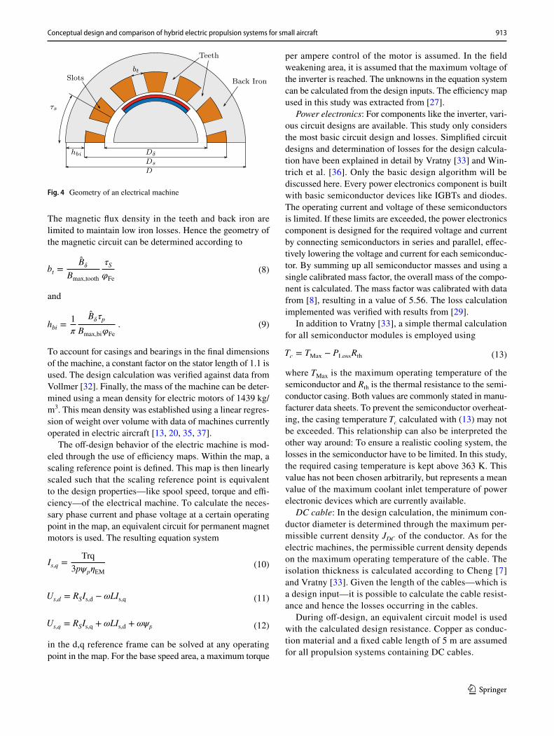
The power factor and the efficiency are estimated inputs of the design calculation. Once the rotor dimensions are known, the stator dimensions can be calculated. The sta-tor consists of ferromagnetic iron sheets with slots for the winding (see Fig. 4). The minimum area necessary for the conductors can be calculated with the maximum allowable current density JS , which depends on the conductor material and cooling of the machine
(5)S =𝜋2
√
2kWAB̂𝛿D
2𝛿lN .
(6)PEM,mech = 3UsIs cos (�)�EM = S cos (�)�EM .
(7)AS =A
JS
�S
�S
.
913Conceptual design and comparison of hybrid electric propulsion systems for small aircraft
1 3
The magnetic flux density in the teeth and back iron are limited to maintain low iron losses. Hence the geometry of the magnetic circuit can be determined according to
and
To account for casings and bearings in the final dimensions of the machine, a constant factor on the stator length of 1.1 is used. The design calculation was verified against data from Vollmer [32]. Finally, the mass of the machine can be deter-mined using a mean density for electric motors of 1439 kg/m3. This mean density was established using a linear regres-sion of weight over volume with data of machines currently operated in electric aircraft [13, 20, 35, 37].
The off-design behavior of the electric machine is mod-eled through the use of efficiency maps. Within the map, a scaling reference point is defined. This map is then linearly scaled such that the scaling reference point is equivalent to the design properties—like spool speed, torque and effi-ciency—of the electrical machine. To calculate the neces-sary phase current and phase voltage at a certain operating point in the map, an equivalent circuit for permanent magnet motors is used. The resulting equation system
in the d,q reference frame can be solved at any operating point in the map. For the base speed area, a maximum torque
(8)bt =B̂𝛿
Bmax,tooth
𝜏S
𝜑Fe
(9)hbi =1
𝜋
B̂𝛿𝜏p
Bmax,bi𝜑Fe
.
(10)Is,q =Trq
3p�p�EM
(11)Us,d = RSIs,d − �LIs,q
(12)Us,q = RSIs,q + �LIs,d + ��p
per ampere control of the motor is assumed. In the field weakening area, it is assumed that the maximum voltage of the inverter is reached. The unknowns in the equation system can be calculated from the design inputs. The efficiency map used in this study was extracted from [27].
Power electronics: For components like the inverter, vari-ous circuit designs are available. This study only considers the most basic circuit design and losses. Simplified circuit designs and determination of losses for the design calcula-tion have been explained in detail by Vratny [33] and Win-trich et al. [36]. Only the basic design algorithm will be discussed here. Every power electronics component is built with basic semiconductor devices like IGBTs and diodes. The operating current and voltage of these semiconductors is limited. If these limits are exceeded, the power electronics component is designed for the required voltage and current by connecting semiconductors in series and parallel, effec-tively lowering the voltage and current for each semiconduc-tor. By summing up all semiconductor masses and using a single calibrated mass factor, the overall mass of the compo-nent is calculated. The mass factor was calibrated with data from [8], resulting in a value of 5.56. The loss calculation implemented was verified with results from [29].
In addition to Vratny [33], a simple thermal calculation for all semiconductor modules is employed using
where TMax is the maximum operating temperature of the semiconductor and Rth is the thermal resistance to the semi-conductor casing. Both values are commonly stated in manu-facturer data sheets. To prevent the semiconductor overheat-ing, the casing temperature Tc calculated with (13) may not be exceeded. This relationship can also be interpreted the other way around: To ensure a realistic cooling system, the losses in the semiconductor have to be limited. In this study, the required casing temperature is kept above 363 K. This value has not been chosen arbitrarily, but represents a mean value of the maximum coolant inlet temperature of power electronic devices which are currently available.
DC cable: In the design calculation, the minimum con-ductor diameter is determined through the maximum per-missible current density JDC of the conductor. As for the electric machines, the permissible current density depends on the maximum operating temperature of the cable. The isolation thickness is calculated according to Cheng [7] and Vratny [33]. Given the length of the cables—which is a design input—it is possible to calculate the cable resist-ance and hence the losses occurring in the cables.
During off-design, an equivalent circuit model is used with the calculated design resistance. Copper as conduc-tion material and a fixed cable length of 5 m are assumed for all propulsion systems containing DC cables.
(13)Tc = TMax − PLossRth
Fig. 4 Geometry of an electrical machine

914 J. Köhler, P. Jeschke
1 3
Battery pack: A battery pack consists of several bat-tery cells connected in series and parallel. Compared to a single cell, multiple cells connected in series can deliver a higher pack voltage, while cells connected in parallel can provide a higher current and higher capacity. Battery packs are therefore inherently scalable depending on the num-ber of battery cells used. However, each cell has specific properties, such as nominal capacity, maximum C-Rate, cell voltage, mass and volume. Additionally, the operat-ing characteristic may vary considerably depending on the cell design and chemistry, as described by Beard [3]. The modeling of a single cell and the pack design is extended from Vratny et al. [34]. The operating characteristics of the cells are modeled through tabulated discharge curves usually provided by the manufacturer. The other proper-ties mentioned above are also provided on the basis of the manufacturer data.
To design the battery pack, mission power demand is inte-grated over time. First, the total required energy, the maxi-mum voltage and the maximum power throughout the mis-sion are calculated. Together with the nominal capacity and maximum C-Rate of a single cell, this gives a first estimate of the required cells in parallel (required capacity and maxi-mum power) and series (required voltage). Subsequently, a discharge cycle over the mission is simulated. With the given discharge characteristic, if any of the conditions
at mission time t are not met, the number of cells in series or parallel are adapted accordingly. If all requirements are met, the number of cells is known and the total cell mass and volume can be calculated. To account for additional mass of the structure, battery management system, cooling system, fuse box and power cabling within the battery pack, factors on mass and volume are used. Based on Nordmann [23], the factor on cell mass is estimated to be 1.25. To determine the battery pack volume, no factor on cell volume could be extracted from the literature, therefore it was estimated at 1.3.
Two different cells and their respective properties are considered during this study. For the parallel hybrid pro-pulsion system, a cell optimized for high power demand [17] is used, since the electric system will only be utilized as a boost during take-off. For the fully electric system, a cell optimized for high gravimetric energy density [24] is employed.
Tank: The fuel demand of the internal combustion engine is integrated over time to calculate the required fuel mass.
(14)Cmax > Ct
(15)Umin < Ut
(16)SOCmin < SOCt
The additional mass of the fuel system is considered accord-ing to Gudmundsson [14].
4 Design space exploration
This chapter analyzes the effects of the most important design variables on system mass and cruise efficiency. The optimum set of design variables for each propulsion system is first summarized. It is on the basis of these optimum val-ues that parametric studies are conducted to highlight the impact of the design variables on mission performance and overall mass of the propulsion system. If a design variable is not changed during a parametric study, it is kept constant at the final value indicated in the respective table.
All propulsion systems in this chapter are optimized for the high thrust ratio requirements in Fig. 1. A MTOM of 1000 kg result in the thrust requirements summarized in Table 3. Since the propeller is the only component affected by the ambient conditions and the propulsion systems are only compared relative to each other, standard day condi-tions are assumed for simplicity. The cruise range is assumed to be 300 km. This value was chosen arbitrarily, to enable a battery sizing. A variation of this requirement will be briefly discussed in chapter 5. For the sake of simplicity, additional mission phases like descend or an alternate route are not considered in this study.
4.1 Internal combustion engine propulsion system
The most important design variables for the IPS were extracted from a sensitivity study and are summarized in Table 4. The propeller design has the biggest impact on the required take-off power and maximum cruise efficiency. The gear ratio would usually be a free design variable as well.
Table 3 Thrust requirements at various operating points
Op.-point Thrust-req.
Take-off 2500 NInit. climb 1600 NMid-climb 825 NCruise 320 N
Table 4 Design variables for the internal combustion engine propul-sion system
Design variables Final value
Name Symbol
Propeller diameter DProp 1.65 mPropeller activity factor fAF 110 –Propeller design lift coef. cDL 0.525 –

915Conceptual design and comparison of hybrid electric propulsion systems for small aircraft
1 3
During this study, however, it is iterated in such a way that the maximum power of the internal combustion engine is reached at take-off without violating the maximum tip Mach number constraint of the propeller (see Table 2).
During the conceptual design of the IPS, the diameter and the design lift coefficient are first optimized. For the given mission requirements, these two design variables have the biggest impact on propulsion system weight and cruise effi-ciency, while the activity factor is less important and hence optimized last.
The effect of propeller diameter and design lift coef-ficient on the propulsion system mass—excluding fuel mass—is shown in Fig. 5. Small propellers lead to a high power requirement during take-off, since the propulsive efficiency declines and the propeller has to be operated at high incidence angles. The mass of the propulsion system components grows in proportion to this power requirement. Assuming a constant propeller diameter, a high design lift coefficient will lead to a better take-off performance, since the propeller can be operated at low incidence while gen-erating the required thrust, resulting in a higher propeller efficiency. These observations correspond to the recommen-dations of Borst [4], that is, the use of high design lift coef-ficients to achieve the smallest propeller diameter and mass.
The influence on system cruise efficiency can be seen in Fig. 6. As already discussed, high take-off power is required for small propeller diameters and design lift coefficients. Therefore a big combustion engine is necessary, which has to operate in deep part load during cruise conditions. This results in low cruise efficiencies. Big propeller diameters and design lift coefficients on the other hand, require small take-off powers and hence a small combustion engine. To efficiently operate big propellers with high design lift coef-ficients during cruise, low rotational speeds are required. Yet the small combustion engine can only provide the cruise power with high rotational speeds, again resulting in
a decreasing system cruise efficiency. Thus for each propel-ler diameter an optimal design lift coefficient can be chosen.
Since a bigger propeller diameter leads to better cruise efficiency and lower propulsion system mass, a maximum permissible diameter of 1.65 m (see Table 2) has been chosen.
Finally, the activity factor is optimized together with the design lift coefficient for the given propeller diameter. The impact on the propulsion system mass and cruise efficiency is much smaller and an activity factor of 110 was chosen for optimum cruise efficiency. The final set of design variables is summarized in Table 4.
4.2 Fully electric propulsion system
The most important design variables of the EPS were extracted from a sensitivity study and are summarized in Table 5. Analogous to the IPS, the propeller geometry is first optimized. This fixes the power demand in each mis-sion point. The gear box and electric components are sub-sequently optimized for the propeller power requirements.
Figure 7 shows the influence of propeller diameter and design lift coefficient on the EPS mass, excluding the bat-tery mass. In comparison to the IPS in Fig. 5, the total mass
Fig. 5 Influence of propeller diameter DProp and design lift coefficient cDL on IPS mass
Fig. 6 Influence of propeller diameter DProp and design lift coefficient cDL on IPS system cruise efficiency
Table 5 Design variables for the fully electric propulsion system
Design variables Value
Name Symbol
Propeller diameter DProp 1.65 mPropeller activity factor fAF 110 –Propeller design lift coef. cDL 0.6 –Gear ratio iEM 5.0 –EM number of pole pairs p 3 –DC voltage level UDC 400.0 V

916 J. Köhler, P. Jeschke
1 3
is significantly lower, since the mass specific power of the electric components is almost twice that of a conventional internal combustion engine. This relationship is also the reason for the rather low sensitivity of the EPS mass to the propeller design, indicating that the EPS has an advantage over the IPS if the propeller diameter is restricted.
This advantage, however, is evened out if the battery is included and the total EPS mass mEPS,total is considered as shown in Fig. 8. Since the target cruise range is 300 km, the battery only has a nominal energy content of roughly 58 kWh, limiting the maximum power of the battery due to the maximum C-rate of the cells. Yet the power requirement at take-off quickly rises with small design lift coefficients and propeller diameters. The battery has to be sized for power and not for energy demand, resulting in very high bat-tery masses. It must be emphasized that this effect depends on the energy content of the battery.
The trend towards high battery masses can be weak-ened if an additional high power battery is considered. The
additional battery mass of the power battery however, will not be compensated by propeller mass savings.
An operational advantage of the EPS over the IPS is shown in Fig. 9. The system cruise efficiency which can be attained is almost independent of the propeller diameter. This can be explained through the off-design characteristic of the electric motor. If necessary, electric motors can be operated at zero rotational speed while still producing a sig-nificant amount of torque. The minimum speed where the electric motor is able to produce the required power is only limited by the maximum torque the motor can produce. In contrast to the electric motor, the internal combustion engine has a minimum speed limit at which a significant torque can be produced. By using an electric motor, the propeller can therefore be operated at low rotational speeds and high effi-ciencies in cruise conditions. Furthermore, the efficiency of the electric motor is much less dependent on speed variation compared to the internal combustion engine.
For the EPS, the propeller design variables have not been chosen for the highest cruise efficiency, but rather the low-est total mass, including all propulsion system components and the battery. Taking into account Fig. 8 and a parametric study of activity factor and design lift coefficient analogue to the IPS, the propeller variables are fixed according to Table 5. In the next conceptual design step, the electric sys-tem is optimized.
Two of the three main design variables considered in this study are the gear ratio iEM and the number of pole pairs p of the electric motor. Since the motor mass primar-ily scales with torque, a high gear ratio and low torque are advantageous. A high number of pole pairs also decreases the electric motor weight, since the required back iron height hbi will be smaller (see Eq. (9)). High rotational speed and a high number of pole pairs will result however, in high electric frequencies, increasing the losses in the
Fig. 7 Influence of propeller diameter DProp and design lift coefficient cDL on EPS mass, excluding battery
Fig. 8 Influence of propeller diameter DProp and design lift coefficient cDL on EPS total mass, including battery
Fig. 9 Influence of propeller diameter DProp and design lift coefficient cDL on EPS system cruise efficiency
917Conceptual design and comparison of hybrid electric propulsion systems for small aircraft
1 3
inverter. For this reason they have to be chosen carefully and cannot be optimized separately.
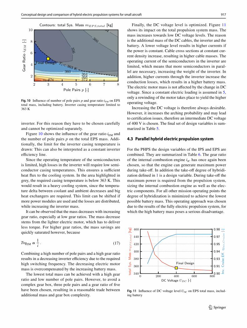
Figure 10 shows the influence of the gear ratio iEM and the number of pole pairs p on the total EPS mass. Addi-tionally, the limit for the inverter casing temperature is drawn: This can also be interpreted as a constant inverter efficiency line.
Since the operating temperature of the semiconductors is limited, high losses in the inverter will require low semi-conductor casing temperatures. This ensures a sufficient heat flux to the cooling system. In the area highlighted in grey, the required casing temperature is below 363 K. This would result in a heavy cooling system, since the tempera-ture delta between coolant and ambient decreases and big heat exchangers are required. This limit can be shifted if more power modules are used and the losses are distributed, while increasing the inverter mass.
It can be observed that the mass decreases with increasing gear ratio, especially at low gear ratios. The mass decrease stems from the lighter electric motor, which has to deliver less torque. For higher gear ratios, the mass savings are quickly saturated however, because
Combining a high number of pole pairs and a high gear ratio results in a decreasing inverter efficiency due to the required high switching frequency. The decreasing electric motor mass is overcompensated by the increasing battery mass.
The lowest total mass can be achieved with a high gear ratio and low number of pole pairs. However, to avoid a complex gear box, three pole pairs and a gear ratio of five have been chosen, resulting in a reasonable trade between additional mass and gear box complexity.
(17)TrqEM ∝1
i.
Finally, the DC voltage level is optimized. Figure 11 shows its impact on the total propulsion system mass. The mass increases towards low DC voltage levels. The reason is the additional mass of the DC cables, the inverter and the battery. A lower voltage level results in higher currents if the power is constant. Cable cross sections at constant cur-rent density increase, resulting in higher cable masses. The operating current of the semiconductors in the inverter are limited, which means that more semiconductors in paral-lel are necessary, increasing the weight of the inverter. In addition, higher currents through the inverter increase the conduction losses, which results in a higher battery mass. The electric motor mass is not affected by the change in DC voltage. Since a constant electric loading is assumed in 5, only a rewinding of the motor takes place to yield the higher operating voltage.
Increasing the DC voltage is therefore always desirable. However, it increases the arching probability and may lead to certification issues, therefore an intermediate DC voltage of 400 V is chosen. The final set of design variables is sum-marized in Table 5.
4.3 Parallel hybrid electric propulsion system
For the PHPS the design variables of the IPS and EPS are combined. They are summarized in Table 6. The gear ratio of the internal combustion engine iIC has once again been chosen, so that the engine can generate maximum power during take-off. In addition the take-off degree of hybridi-zation defined in 1 is a design variable. During take-off the maximum power is required from the propulsion system, sizing the internal combustion engine as well as the elec-tric components. For all other mission operating points the degree of hybridization is minimized to achieve the lowest possible battery mass. This operating approach was chosen due to the results of the fully electric propulsion system, for which the high battery mass poses a serious disadvantage.
Fig. 10 Influence of number of pole pairs p and gear ratio iEM on EPS total mass, including battery. Inverter casing temperature limited to 363 K
Fig. 11 Influence of DC voltage level UDC on EPS total mass, includ-ing battery

918 J. Köhler, P. Jeschke
1 3
For the following study, the electric system will be used to assist the internal combustion engine during the high power demands (in this particular case during take-off and init. climb conditions). This enables a downsizing of the combustion engine, which may be beneficial if power demands differ strongly between take-off and cruise condi-tions. The downsizing process of the combustion engine not only influences the efficiency during low power demands, but also the operating range of the combustion engine. This relationship shall be explained in the following and is quali-tatively illustrated in Fig. 12, where the power demands at take-off and cruise are shown as well as the operating limits of a reference motor and a downsized motor. For the sake of simplicity, it is assumed that the combustion engine is down-sized by eliminating cylinders, keeping all other geometric parameters constant. Therefore the maximum and minimum speed limits of the motor are constant as well. Furthermore it is assumed that the propeller design and therefore the power demands for take-off and cruise remain constant. The fol-lowing discussion therefore only incorporates changes to the combustion engine.
Due to the downsizing, the maximum torque produced by the engine decreases. The downsized motor can-not provide the take-off power any more. The power gap between required take-off power and maximum power of
the combustion engine is filled by the electric motor. The downsized motor can then operate at optimum efficiency during cruise, while the bigger motor has to be operated at part load with a lower efficiency.
At the same time, the rotational speed range in which the motor can provide the cruise power, is much smaller for the downsized motor. Assuming a constant gear ratio chosen at take-off, this will result in a high rotational speed of the pro-peller at cruise conditions and, depending on the propeller design, low propeller efficiencies. We can deduce from this relationship that the degree of hybridization and the propel-ler geometry cannot be chosen independently.
Apart from choosing an appropriate propeller design, another option may remedy this problem: Instead of using a conventional spur gear box, a planetary gear box – sum-ming the rotational speeds of the electric motor and combus-tion engine – can be employed. This will give an additional degree of freedom, since the gear ratio of the combustion engine can be chosen freely, while still using the engine to its full potential during take-off. However, this option is outside the scope of this study.
Figure 13 shows the influence of the three design vari-ables – propeller diameter, design lift coefficient and degree of hybridization – on system cruise efficiency and the pro-pulsion system mass. In the system mass, only the mass of the power converting components and the battery mass are included. Fuel mass is not included. Three parametric studies at three different take-off degrees of hybridization between 0 and 0.5 were conducted. Zero hybridization is equal to the IPS. In each study, the propeller diameter was varied between 1.45 and 1.65 m and the design lift coef-ficient between 0.36 and 0.6.
With an increasing degree of hybridization, the propul-sion system mass decreases, since the mean power density of all the electric components is higher than the power density of the internal combustion engine. In this case the optimum degree of hybridization regarding mass and cruise efficiency is close to 0.5. With significantly higher degrees of hybridization the combustion engine can no longer pro-vide the required mid-climb power. As a result the battery mass would increase significantly. In addition, the cruise efficiency of the combustion engine could only be improved marginally.
The aforementioned downsizing effect on propeller effi-ciency during cruise is visible for high degrees of hybridi-zation. The propeller efficiency decreases quickly for big propeller diameters and design lift coefficients, overcompen-sating the efficiency gains in the internal combustion engine and resulting in a lower overall system cruise efficiency.
A comparison of the PHPS ( HP,TO = 0.5) and the IPS ( HP,TO = 0) enables a discussion on the potential mass sav-ings and efficiency gains between the two propulsion sys-tems. The propeller of the PHPS can either be designed for
Table 6 Design variables for the parallel hybrid propulsion system
Design variables Value
Name Symbol
Propeller diameter DProp 1.65 mPropeller activity factor fAF 110 –Propeller design lift coef. cDL 0.36 –Degree of hybridization HP,TO 0.46 –EM gear ratio iEM 4.0 –EM number of pole pairs p 4 –DC voltage level UDC 400.0 V
Fig. 12 Effect of downsizing the internal combustion engine

919Conceptual design and comparison of hybrid electric propulsion systems for small aircraft
1 3
lowest propulsion system mass, resulting in a low cruise effi-ciency, or the highest cruise efficiency, resulting in a higher propulsion system mass. Compared to the IPS, at the most, 10% of propulsion system weight can be saved. In terms of cruise efficiency, at the most 2.5 percentage points can be gained, corresponding to 11% in fuel savings during cruise. The propulsion mass saving potential should be interpreted as a maximum potential, since the thermal management is not included in the mass. If liquid cooling is used, two sepa-rate cooling systems for the electric components and com-bustion engine might be necessary, since the temperature levels are very different. These circumstances will lead to a lower mass saving potential.
During this study, the PHPS is optimized for cruise effi-ciency, bearing in mind the trade-off between efficiency and mass previously discussed. After fixing the propeller geometry and degree of hybridization, the electric system is optimized by adopting the same approach presented in chap-ter 4.2. Since the underlying design trades are the same and are already explained in chapter 4.2, they are not detailed again. The final set of design variables is summarized in Table 6.
5 Propulsion system comparison under varying mission requirements
This section compares the propulsion systems investigated under varying thrust requirements. Each propulsion system was designed according to the method described in chap-ter 4. To vary the mission thrust requirements, considera-tion is given to the two sets of thrust requirements shown in Fig. 1. For the low thrust ratio requirement, the take-off to cruise thrust ratio is roughly 4.5 while the same ratio for the high thrust ratio requirement is 7.8. As metrics for comparison, the cruise efficiency and the total propulsion
system mass, including energy storage, were chosen. The final values are shown in Table 7. In addition, values nor-malized to the IPS are given to facilitate comparison. The absolute results stated are depending on the specific use case. Due to the power and energy dependency of the bat-tery, the relative comparison between the IPS and the EPS are also depending on the specific use case. Especially it is dependent on the relation between mission energy and take-off power demand, as will be shown later. However the relative comparison of mass and efficiency between the IPS and PHPS mainly depends on the thrust and power ratios and is therefore independent of the specific use case investigated in this paper.
For low thrust ratios between take-off and cruise, the PHPS is slightly heavier than the IPS. Nevertheless, it does offer a small improvement in cruise efficiency by 2%. How-ever, this marginal advantage does not justify the additional complexity of the PHPS. For high thrust ratios between take-off and cruise, again, the total mass of the PHPS and IPS are comparable. However, the PHPS has a cruise efficiency advantage of 12%.
Fig. 13 Influence of propel-ler diameter DProp , design lift coefficient cDL and take-off degree of hybridization HP,TO on PHPS mass and system cruise efficiency
Table 7 Comparison of propulsion systems for varying thrust requirements
Low thrust ratio IPS EPS PHPS
mtotal 117 kg 400 kg 119 kg�Cruise 0.253 0.825 0.259Mass rel. to IPS 1.00 3.42 1.02Eff. rel. to IPS 1.00 – 1.02
High thrust ratio IPS EPS PHPS
mtotal 150 kg 355 kg 148 kg�Cruise 0.230 0.81 0.257Mass rel. to IPS 1.00 2.37 0.99Eff. rel. to IPS 1.00 – 1.12

920 J. Köhler, P. Jeschke
1 3
The efficiency advantage for high thrust ratios stems from the widely spread propeller power requirements in the dif-ferent mission points. Converting the thrust requirements via the propeller to power requirements, the low thrust ratio requirement results in a take-off to cruise power ratio of roughly 2.2 while the same ratio for the high thrust ratio requirement is 4.5. A big power ratio results in a poor cruise efficiency for the IPS, since the internal combustion engine is operated in deep part load. By using an additional power source during take-off, the internal combustion engine can be downsized and a better cruise efficiency reached (see also Fig. 12).
The efficiency advantage therefore, depends on the power ratios between the different mission points. In turn, the power ratios depend on the trust ratios in conjunction with the propeller efficiencies at the respective operating condi-tions, since
Hence for a given thrust ratio, the use of a PHPS may be particularly advantageous if the propeller design is limited by additional constraints. This may be a maximum diam-eter limit or a lower tip Mach number requirement during take-off in order to limit noise. Both lead to low propeller efficiencies during take-off and therefore to a bigger power ratio between take-off and cruise. The increasing advantages of the PHPS for a limited propeller diameter can also be observed in Fig. 13.
Compared to the IPS, the EPS is much heavier for both sets of thrust requirements. The reason is the heavy battery, although the required cruise range was only set to 300 km. Increasing the cruise range would also increase the battery mass. Not surprisingly, a fully electric propulsion system is therefore only feasible for short cruise ranges.
For high thrust ratios between take-off and cruise how-ever, the factor between IPS and EPS total mass is much smaller. The difference can be explained as follows: The increased take-off power results in a mass increase from 117 to 150 kg for the IPS. Excluding the battery, the mass of the electric components of the EPS only increases from 47 to 59 kg, reducing the mass difference. The battery mass however is the predominant reason. It decreases from 352 to 296 kg. While the (short) take-off power requirement increases with wing loading, all other power requirements (e.g. mid-climb, cruise) decrease. This results in a much lower energy demand during the mission and consequently in a smaller battery. While the design for low thrust ratios requires a battery with a nominal energy of 70 kWh, the design for high thrust ratios only requires 59 kWh.
The conclusion might be made that—ignoring the stall speed limit—a higher wing loading than the highest one
(18)PProp =Fc0
�Prop.
chosen (see Fig. 1) is even better for the EPS, since the cruise thrust required then decreases even further. However, this is not the case. The reduced capacity of the battery also limits the maximum power output of the battery due to the maximum C-rate of the used cells. A further increase in the wing loading, and therefore the take-off power requirement, will quickly increase the battery mass, since it has to be sized by power and not by energy demand.
The optimum ratio between maximum power demand and mission energy can be estimated by calculating the maxi-mum battery power according to
with EBat being the nominal energy stored in the battery and Cmax the maximum C-rate of the used cells. This minimum mass criterion is only valid if a single battery is used. It may be feasible to use an additional high power battery pack to reduce the power requirement for the high energy battery pack during take-off.
In terms of cruise efficiency, the EPS has one major advantage, since it is not limited by the Carnot efficiency. A direct comparison is therefore not feasible.
In conclusion, with today’s technology, the EPS has a severe mass disadvantage when compared to the IPS, even for short ranges. This disadvantage is minimized by balanc-ing the energy and power demand throughout the mission. Nevertheless, it remains significant even for the aerodynami-cally very efficient aircraft type that was assumed and at a small cruise range of 300 km.
6 Summary and outlook
In this paper, a conceptual design method for hybrid elec-tric propulsion systems in small aircraft is proposed and exemplified. Three propulsion systems are investigated, namely the internal combustion engine, parallel hybrid and the fully electric propulsion system. For each of these propulsion systems, the most important design variables are varied and their impact on the overall mission perfor-mance and system mass is investigated. The conducted studies highlight the importance of a profound system knowledge paired with a suitable tool during the con-ceptual design stage. Only if both aspects are satisfied, an optimal system design is possible. For instance it is shown, that for a parallel hybrid propulsion system the degree of hybridization and the propeller geometry can-not be optimized independently. The propeller geometry has an impact on the optimum spool speed during cruise, while high degrees of hybridization may limit the operat-ing speed range of the internal combustion engine. Finally, the hybrid and electric propulsion system are compared
(19)PBat,max = EBatCmax ,

921Conceptual design and comparison of hybrid electric propulsion systems for small aircraft
1 3
to the conventional internal combustion engine system. Potential fields of application are highlighted by varying the thrust requirements.
It is shown that for specific power requirements the parallel hybrid propulsion system may offer advantages in terms of system mass and cruise efficiency over the conventional internal combustion engine system. The pro-peller design is decisive if either efficiency or system mass advantages are to be fully exploited. The key parameter in determining whether a parallel hybrid is a beneficial solu-tion is the maximum power ratio required throughout the mission, that is, the highest power demand in relation to the lowest power demand. This study suggests that advan-tages can be expected if the power ratio is bigger than 2.2. For the systems investigated here, at a power ratio of 4.5, the cruise efficiency could be improved by 12 % in relation to the internal combustion engine system.
For the fully electric propulsion system, one advantage over the internal combustion engine system in terms of operability is shown. The spool speed range of the electric motor which drives the propeller is much wider, compared to the internal combustion engine. In addition, the effi-ciency changes of the electric motor are small. Through-out the mission, the propeller can therefore be operated at maximum efficiency for the required thrust. However, the battery is responsible for a severe mass disadvantage. It is shown, that the battery mass can be minimized if the power and energy requirements throughout the mission are carefully balanced. Nevertheless, for the specific use case with a target cruise range of 300 km at 260 km/h, the fully electric system mass is higher by a factor of three in com-parison to the lightest internal combustion engine system. This mass disadvantage may decrease with future battery developments, but given today’s battery technology, the fully electric propulsion system would not seem feasible, especially for long cruise ranges. However, additional design targets, like minimum CO2 emissions or low oper-ating costs may be a driver in implementing the heavier fully electric system with future battery technology.
Subsequent publications will investigate the series propulsion system. So far, only preliminary data is avail-able. Compared to a simple combustion engine, efficiency is much lower, although the efficiency of the individual electric components connecting propeller and combustion engine is rather high. The reason for this is the high num-ber of components necessary for the dual power conver-sion. In addition, more components have to be sized for the total power required, resulting in a heavier system. Nevertheless, the series propulsion system offers new pos-sibilities of propulsion system integration, which may be desirable.
Funding Open Access funding enabled and organized by Projekt DEAL.
Open Access This article is licensed under a Creative Commons Attri-bution 4.0 International License, which permits use, sharing, adapta-tion, distribution and reproduction in any medium or format, as long as you give appropriate credit to the original author(s) and the source, provide a link to the Creative Commons licence, and indicate if changes were made. The images or other third party material in this article are included in the article's Creative Commons licence, unless indicated otherwise in a credit line to the material. If material is not included in the article's Creative Commons licence and your intended use is not permitted by statutory regulation or exceeds the permitted use, you will need to obtain permission directly from the copyright holder. To view a copy of this licence, visit http:// creat iveco mmons. org/ licen ses/ by/4. 0/.
References
1. AMPAIRE INC.: Ampaire (2020). https:// www. ampai re. com/. Retrieved 17 Aug 2020
2. Balazs, A.: Optimierte Auslegung von ottomotorischen Hybri-dantriebssträngen unter realen Fahrbedingungen. PhD thesis, RWTH Aachen, Aachen (2015)
3. Beard, K.: Linden’s handbook of batteries. McGraw-Hill Educa-tion, New York (2019)
4. Borst, H.: Summary of propeller design procedures and data. Volume 1. aerodynamic design and installation. Tech. rep., Borst H. and Associates (1973)
5. Brown, G.V., Kascak, A.F., Ebihara, B., Johnson, D., Choi, B., Siebert, M., Buccieri, C.: NASA Glenn Research Center pro-gram in high power density motors for aeropropulsion. Tech. rep, NASA, Glenn Research Center (2005)
6. BRP-Rotax GmbH & Co. KG: Operators Manual for Rotax Engine Type 915 i A Series. Ed.0, Rev.1, June 1, 2019
7. Cheng, F.: Insulation thickness determination of polymeric power cables. IEEE Trans. Dielectr. Electr. Insul. 1(4), 624–629 (1994)
8. Dvorský, G.: HBC—SERIES V7 300400-3, 400400-3, Operat-ing manual (2020)
9. e.SAT GmbH: Silent Air Taxi (2020). https://e- sat. de/ de/ silent- air- taxi/. Retrieved 17 Aug 2020
10. Falck, R., Chin, J., Schnulo, S., Burt, J., Gray, J.: Trajectory optimization of electric aircraft subject to subsystem thermal constraints. Presented at the (2017)
11. Filipenko, M., Biser, S., Boll, M., Corduan, M., Noe, M., Ros-tek, P.: Comparative analysis and optimization of technical and weight parameters of turbo-electric propulsion systems. Aero-space 7, 107 (2020)
12. GasTurb GmbH: Gas turbine performance software (2020). https:// gastu rb. de/. Retrieved 19 Aug 2020
13. Geiger, J.: Handbuch, Elektrisches Antriebssystem (2019) 14. Gudmundsson, S.: General aviation aircraft design: applied meth-
ods and procedures. Butterworth-Heinemann, Oxford (2013) 15. Huß, M.: Übertragung von Motoreigenschaften mit Hilfe charak-
teristischer Skalierfunktionen zur Simulation verschiedener Vari-anten von Ottomotoren. Ph.D. thesis, Universität München (2013)
16. Juretzko, P., Immer, M., Wildi, J.: Performance analysis of a hybrid-electric retrofit of a RUAG Dornier Do 228NG. CEAS Aeronaut. J. 11(1), 263–275 (2019)
17. Kokam Co., Ltd.: Specification for SLPB8643128H5 (2010) 18. Kreimeier, M., Stumpf, E.: Benefit evaluation of hybrid electric
propulsion concepts for CS-23 aircraft. CEAS Aeronaut. J. 8(4), 691–704 (2017)

922 J. Köhler, P. Jeschke
1 3
19. LTH Koordinierungsstelle: Luftfahrttechnisches Handbuch (2006). https:// www. lth- online. de/
20. MAGicALL, Inc.: Magidrive electric motors (2020). https:// www. magic all. biz/ produ cts/ integ rated- motor- contr oller- magid rive/. Retrieved 19 May 2021
21. Mattingly, J., Heiser, W., Pratt, D.: Aircraft engine design. Ameri-can Institute of Aeronautics and Astronautics, Reston (2002)
22. Müller, G., Vogt, K., Ponick, B.: Grundlagen elektrischer maschinen, vol. 2. Wiley, Amsterdam (2014)
23. Nordmann, J.: Batterietechnologie für Flugantriebe—Methoden und Umsetzung in der Praxis (2019). Lecture presentation
24. Panasonic Corporation: Specifications NCR18650B (2018) 25. Rings, R., Ludowicy, J., Finger, D., Braun, C.: Sizing studies
of light aircraft with parallel hybrid propulsion systems. 67. Deutscher Luft-und Raumfahrtkongress DLRK 2018 (2018)
26. Rizzoni, G., Guzzella, L., Baumann, B.: Unified modeling of hybrid electric vehicle drivetrains. IEEE/ASME Trans. Mecha-tron. 4(3), 246–257 (1999)
27. SciMo GmbH: SciMo Sy43 (2020). https:// sci- mo. de/ motor en/. Retrieved 17 Aug 2020
28. Seibel, J.: Optimierte Auslegung von Ottomotoren in Hybrid-Antriebssträngen. Ph.D. thesis, RWTH Aachen, Aachen (2008)
29. Semikron International GmbH: Semisel v5 (2020). https:// semis el. semik ron. com/#/ home. Retrieved 17 Aug 2020
30. Standard, H.: Generalized method for propeller performance esti-mation. Hamilton Standard, Windsor Locks, CT, Standard No. PDB 6101 (1963)
31. Strathoff, P., Savic, H.A., Stumpf, E.: Performance comparison of conventional, hybrid-electric, and all-electric powertrains for small aircraft. Presented at the (2020)
32. Vollmer, U.: Entwurf,: Auslegung und Realisierung eines ver-lustoptimierten elektrischen Antriebs für Hybridfahrzeuge. Ph.D. thesis, Technische Universität Berlin (2012)
33. Vratny, P.: Conceptual design methods of electric power architec-tures for hybrid energy aircraft. Ph.D. thesis, Technische Univer-sität München, München (2019)
34. Vratny, P., Gologan, C., Pornet, C., Isikveren, A., Hornung, M.: Battery pack modeling methods for universally-electric aircraft, pp. 525–535. Linköping Univ. Electronic Press, Linköping (2013)
35. Willi, T., Andrey Alekseevich, S.: Specifications of Siemens Motors: SP260D, SP55D. Taken from “World Directory of Light Aviation, Issue of 2018–2019” (2018)
36. Wintrich, A., Nicolai, U., Tursky, W., Reimann, T.: Application manual power. Semiconductors (2011)
37. Yuneec International Ltd: Power systems (2012). https:// web. archi ve. org/ web/ 20120 71211 5804/ http:// www. yuneec. com/ Power Motor_ Tech_ spec. html. Retrieved 19 May 2021
Publisher's Note Springer Nature remains neutral with regard to jurisdictional claims in published maps and institutional affiliations.