Embed Size (px)
Citation preview

Concept Development of an
Electromechanical Cylinder – With a Cascade Gear Unit
KARL BERGQVIST LINN SEVEFJORD
Master of Science Thesis
Stockholm, Sweden 2014


Concept Development of an Electromechanical Cylinder
-With a Cascade Gear Unit
Karl Bergqvist Linn Sevefjord
Master of Science Thesis MMK 2014:46 MPI03
KTH Industrial Engineering and Management
Machine Design
SE-100 44 STOCKHOLM


Master of Science Thesis MMK 2014:46 MPI 03
Concept Development of an Electromechanical Cylinder
- With a Cascade Gear Unit
Karl Bergqvist
Linn Sevefjord
Approved
2014-06-18
Examiner
Gunilla Ölundh Sandström
Supervisor
Stefan Björklund
Commissioner
CorPower Ocean
Contact person
Patrik Möller
Abstract A new invention has been developed by CorPower Ocean; a mechanical rack and pinion solution
called a cascade gearbox. The primary function of the gearbox is transforming a linear motion
into a rotational motion. The novelty is its unique properties; it is capable of combining heavy
loads and high velocities, and at a high efficiency. CorPower Ocean is aiming at finding
applications where the gearbox’s unique properties can be of use. If the gearbox is combined
with a motor it forms an electromechanical actuator. Therefore, an investigation of applications
using actuators has been targeted. More specifically, the master thesis assignment was to
examine in which applications the transition of a cascade electromechanical actuator was
technically viable. Research questions that derived was to answer if an implementation of an
cascade electromechanical cylinder is technically feasible and if it implicates improved results
regarding environmental related goals.
The methodology executed to finalize the project included several stages. The first stage was the
background study which consisted of reviewing trends and gathering technical data for case
studies of targeted applications. The targeted applications were heavy lifting equipment and
injection molding machines. With the help of CorPower software, gearbox dimensioning
examples were drafted and could be evaluated from a size and weight perspective. To further
evaluate potential applications, interviews were conducted with targeted equipment
manufacturers. The selection of applications was completed by evaluating the interview
responses and the drafted gearbox examples.
Chosen applications were ultimately a nine tonnes forklift and an empty container handler,
mainly due to good customer response, integration ability and potential of performance
enhancement. An optimisation was performed to achieve a concept solution that satisfied
customer needs such as low cost and a slim design. In order review the business cases in each
application, energy savings and performance cases were conducted, benchmarking against the
hydraulic solution. In the ECH case, the energy saved was 54% and the productivity increased
with 9.6%. In the forklift case, the energy saved was 52% and the productivity increased with
1%. Both of applications have great potential of a transition from hydraulic cylinders to
electromechanical cylinders in terms of implementation and technical feasibility. The final
concept solutions exceeded the hydraulics in performance, retaining a slim and acceptable size
and design. Furthermore, this sector of heavy lifting equipment had high potential for
electrification which can contribute to reduced emissions and fuel savings.
Keywords: electromechanical cylinders, concept development, cascade gearbox


Examensarbete MMK 2014:46 MPI 03
Konceptutveckling av elektromekanisk cylinder
-med en kaskadväxelenhet
Karl Bergqvist
Linn Sevefjord
Godkänt
2014-06-18
Examinator
Gunilla Ölundh Sandström
Handledare
Stefan Björklund
Uppdragsgivare
CorPower Ocean
Kontaktperson
Patrik Möller
Sammanfattning En ny innovation har utvecklats av CorPower Ocean; en mekanisk rack och pinjonglösning
kallad kaskadväxel. Dess primära funktion är att transformera en linjär rörelse till en roterande
rörelse och vice versa. Nyhetsvärdet är växellådans unika prestanda; den kan hantera
kombinationen av höga laster och höga hastigheter till en hög verkningsgrad. Nu önskar
CorPower Ocean att hitta applikationer där kaskadväxelns unika prestanda kommer till
användning. Om kaskadväxeln kombineras med en motor bildas en elektromekanisk aktuator,
och därför har en utredning av applikationer som använder aktuatorer utsetts som en marknad att
undersöka närmare. Mer specifikt var examensuppdraget att undersöka i vilka applikationer en
sådan övergång skulle vara genomförbar ur ett tekniskt perspektiv. Forskningsfrågor som
önskades besvaras var huruvida en sådan övergång är genomförbar ur ett tekniskt perspektiv och
om en sådan implementation innebär förbättringar vad gäller miljörelaterade mål.
Metodologin som användes för att slutföra projektet utgjordes av flera steg. Första steget var att
genomföra en bakgrundsstudie om elektrifiering och produkttrender samt samla teknisk data på
utsedda applikationer. De utsedda övergångsområdena var maskiner för tunga lyft samt
plastformssprutningsmaskiner. Med CorPowers mjukvara kunde dimensioneringsexempel göras
för kaskadväxellådor och utvärderas utifrån sin storlek och vikt. För en fortsatt utvärdering av
applikationer genomfördes intervjuer med tillverkare av de utsedda applikationerna. Val av
applikationer slutfördes genom att utvärdera svar från målkunder samt dimensioneringsexempel
av växellådorna.
De valda applikationerna blev slutligen en nio tons gaffeltruck och en tomcontainertruck. Valet
baserades huvudsakligen på bra respons från kunder, bra integrationsmöjligheter samt potentiella
prestandaförbättringar. Fokus låg på att byta ut lyftcylindrarna och bortse från övriga mindre
cylindrar. Lösningarna optimerades för att matcha kundkrav så som kostnad och passform.
Ett energibesparingscase utfördes för att jämföra kaskadlösningen med nuvarande hydrauliska
lösning. I tomcontainertruckens fall sänktes energiförbrukningen med 54 % och produktiviteten
ökade med 9.6%. I gaffeltruckens fall sjönk energiförbrukningen med 52 % och produktiviteten
ökade med 1 %. Båda applikationerna uppvisade stor potential för ett byte från hydraulcylindrar
till elektromekaniska cylindrar. De slutgiltiga koncepten överträffade hydraulikens prestanda
medan de bibehöll en acceptabel storlek. Vidare fanns det en stor potential inom lyftindustrin att
genom elektrifiering kunna minska utsläpp och bränsleförbrukning.
Nyckelord: elektromekanisk cylinder, konceptutveckling, kaskadväxel


Acknowledgements
We, the authors of this master thesis, are students of the master program Product Innovation
Management at the Royal Institute of Technology in Stockholm. There are many that we
would like to acknowledge in this work that took place during spring 2014.
First of all, appreciation is directed to the CorPower Office for assigning us this thesis, it has
been truly inspiring to be a part of a technology intense and innovative company.
A special thanks to Patrik Möller for the encouragement, the entrusted confidence, and the
ever great support.
We would like to direct thanks to Stefan Svensson and André Hellestig for all helpful advice
and design support.
A thanks goes to Hans Hansson at SwePart for providing great “outside-the-box-thinking”,
useful contacts and introducing the candidate workers Simon Andersson and Sebastian
Gunnarsson who also deserves a thanks for consulting and sharing of ideas.
Further we would like to thank our interviewees and company contacts for their time, the
interest shown and the essential and valuable information received from questionnaires and
during meetings.
Finally we would like to thank our supervisor Stefan Björklund for valuable meetings.
Karl Bergqvist and Linn Sevefjord
Stockholm, June 2014


Table of Contents
1 INTRODUCTION 1
1.1 Project Background and Problem Description 1
1.2 Purpose and Definition 2
1.3 Nomenclature 3
1.4 Abbreviations 3
2 FRAME OF REFERENCE 4
2.1 The CEMC concept 4
2.2 Existing linear actuator solutions 5
2.3 Driving factors towards electrification 7
2.4 Product trends 9
3 IMPLEMENTATION 13
3.1 Methodology 13
3.2 Methods 14
4 PRODUCT CASE STUDIES 17
4.1 Reachstackers 17
4.2 Forklifts 18
4.3 Container Lift Trucks 19
4.4 Injection Molding Machines 20
5 EVALUATION 22
5.1 Evaluation of Case Studies 22
5.2 Evaluation of CEMC concept alternatives 26
6 FINAL CONCEPTS 32
6.1 Lifetime and load case 32
6.2 Final concept: ECH 34
6.3 Final concept: Electric forklift 38
7 BUSINESS CASE 41
7.1 Business case: ECH 41
7.2 Business case: Forklift 42
7.3 Benchmarking 44

8 ANALYSIS 45
8.1 ECH 45
8.2 Forklift 46
8.3 Environmental goals 46
9 DISCUSSION 48
10 CONCLUSIONS 49
11 FUTURE WORK 50
12 REFERENCES 52
INTERVIEW MATERIAL - 1 - APPENDIX A
QUESTIONNARE - 4 - APPENDIX B
CASE STUDY: REACH STACKERS - 8 - APPENDIX C
CASE STUDY: FORKLIFTS - 13 - APPENDIX D
CASE STUDY: LIFT TRUCKS - 14 - APPENDIX E
QUESTIONNAIRE RESPONSES - 15 - APPENDIX F


1
1 Introduction
This chapter describes the goal and purpose of the master thesis along with the background
and delimitations.
1.1 Project Background and Problem Description
A new innovative type of gearbox has been developed by a wave energy company. It is a
mechanical rack and pinion solution called a cascade gear. The basic function of the gearbox
is transforming a vertical motion into a rotational motion and vice versa. The novelty value of
the gearbox is the geometry of how the pinions and the gears work together along with flexing
units. Eight pinions shares the force from the rack which is evenly distributed. The invention
enables unique capabilities; it can handle high forces and high velocities at the same time. The
high velocity is transferred to high rotational speeds of the pinions, without scaling the size of
them. Another important benefit of the cascade gear is its high efficiency.
The cascade gear technology is today a critical component in the powertrain of a wave energy
converter for use in harsh oceanic environments. It transforms an oscillating vertical motion
of the waves into a rotating motion which powers two generators.
The innovation is developed and patented by CorPower Ocean AB which is aiming to
broaden the use of the cascade gear, and several markets have already been identified. The
cascade gear is suitable for integration with electrical motors to create electromechanical
cylinders (EMC), which are electrical actuators. Having an EMC with a cascade gear unit
enables the combination of heavy loads with high linear velocities. This is typically hard to
achieve with hydraulic cylinders.
Hydraulic cylinders are widely used in many different applications where high forces are
required. Heavy lifting and construction equipment are targeted applications where hydraulic
actuators are used extensively. Considering trends in the actuator market, many manufacturers
are marketing EMCs as the successor of hydraulics. In comparison the cascade EMC (CEMC)
is more energy efficient, has higher controllability, is faster and is reversible, which means
that when going backwards it can generate power using its electric motor as a generator. This
can be used, for example, when a forklift lowers its load. What differentiates the CEMC from
other EMCs on the market is that they all use ball screws or worm gears to transform the
torque to a linear force. Ball screws and worm gears have limitations regarding the
combination of speed and load, as well as stroke.
The environmental advantages of electro mechanics are several, mainly considering oil
leakage and recycling as well as energy consumption. During a lifecycle of a machine the
energy efficiency is tremendous in comparison with hydraulics. Besides the efficiency an
electric machine consists of less components and the downtime and required maintenance
hours are greatly reduced. (Beijer Electronics, 2012)
Considering the lack of actuators in the market delivering high forces at a high speed with a
good efficiency, this is a particular interesting solution to investigate. Not only to investigate
the technical feasibility, but also study the potential of improvement regarding environmental
aspects.

2
CorPower Ocean is working together with SwePart Transmission which is a company
specialised in manufacturing gears and gear applications. SwePart, with their knowledge in
transmissions, will help review the design and manufacture the complete gearbox.
1.2 Purpose and Definition
The project task is to investigate the viability of replacing hydraulic cylinders with
electromechanical cylinders based on the cascade gear units. Also examine in which
applications the transition is technically viable and economically promising. Viability
concerns among others the required space for switching a fairly slim hydraulic cylinder with a
gearbox, a rack and a motor and the gains or losses in energy consumption.
To provide a solid basis for evaluation of the application cases, a review of trends in heavy
lifting and industrial machines was first made, as a background study.
The deliverables of the concept development should be two final concepts including CAD
models, integration in customer equipment and business case reviews.
Research Questions
Two research questions can be formed considering purpose and aim of the study.
1. Is the CEMC concept technically viable in selected applications?
2. Does the concept of CEMC contribute to improvement in environmental related
goals?
Delimitations
The project was planned to be carried out during twenty weeks excluding holidays, starting
January 27. Limitations were made towards the number of applications that would be
investigated based on available time.
Customer contact was only established with Swedish manufacturers, which had an impact on
the selection of equipment.
Regarding the details in the final concept, the main components were discussed and evaluated,
but final decisions of motor and motor drives was left out, as well as smaller components.

3
1.3 Nomenclature
N Newton
W Watts
V Volt
J Joule
m meter
g gram
t tonne
rpm revolutions per minute
m/s meter per second
Nm Newton meter
bar bar
Pa Pascal
ft feet
1.4 Abbreviations
EMC Electromechanical cylinder
CEMC Cascade electromechanical cylinder
CO2 Carbon dioxide
SEC Specific energy consumption
ECH Empty container handler
IMM Injection molding machine

4
2 Frame of Reference
The background study consists of information regarding trends in electrification and different
applications; it should identify possibilities of a CEMC solution. First an introduction to the
CEMC concept and other existing solutions of linear actuators is presented.
2.1 The CEMC concept
The CEMC is a linear actuator, which means a powered linear axle, which in this case is a
rack that is powered in and out through the cascade gear box. The gear house is fixed and its
stroke represents the maximum extended length of the rack while still being enclosed by the
gearbox.
The dimensions and performance parameters can be adjusted for the cascade gearbox.
Depending on requirements and situation, the gearbox can be dimensioned to fit different
purposes. This implies that applications can range from smaller solutions where low force
handling is required, up to loads of several hundreds of tonnes. The main components of the
CEMC concept are described briefly below.
Gearbox
The gearbox is a cascade gear unit containing eight pinions and two gear steps allowing a
total gear ratio of 25, five per each gear step. It allows rack speeds of up to 5 m/s. The
gearbox will be dimensioned for specific applications and operating conditions.
Cylinder
The cylinder that covers the rack below the gearbox is used to protect the rack and can be
used as a pressure vessel if a gas spring is used. The cylinder also works as mounting of the
EMC.
Gas spring
A gas spring is optional and could be used for compensating weight of the rack and lifting
assembly. A gas spring puts a pressure on the rack, and the correspondent force applied is
considered constant due to a big gas reservoir, typically 10 times the stroke volume of the
cylinder allowing a maximum of 10% compression. This reduces compression related heat
and heat associated energy losses.
Bellow
There are different options of how to protect the extending rack from the surrounding
environment. Bellows typically have a high compression ratio which minimises the stroke
reserved by the height of the retracted protection.
Mechanical brake
A mechanical normally closed brake is implemented to secure the load and serve as an
emergency brake in case of power loss. Normally closed means it is closed if not powered and
kept open.

5
Motor
An electrical motor powers the EMC. The motor will vary depending on application and
dimensioning of the gearbox. Several integration options enable different types of motors.
Applying an external planetary gear is a possibility to modify the gear ratio. There is also a
motor drive included in the concept.
Figure 2:1 shows a design example of a CEMC in extended position with the included main
components.
Figure 2:1. A design example of a CEMC in extended position.
2.2 Existing linear actuator solutions
There are several solutions for achieving an axial force and a linear motion. An introduction
to hydraulic, pneumatic and electromechanical actuators is presented here.
Motor
Cylinder
Bellow
Cascade
gearbox

6
Hydraulic actuators
Hydraulic cylinders are vastly used in a wide range of areas, such as energy, industry, marine
and mobile equipment. Its major advantage is the amount of axial force that can be retrieved
from a very slim cylinder. It can have a power stroke in one or both directions.
The hydraulic cylinder solution has a limitation in speed. The piston cannot move too fast
with large forces, if so the seals are burned. Other disadvantage is the required service and oil
exchange and the possibilities of leakage. Leakage is highly undesired in hygienic industries,
like food and medicine.
A hydraulic system includes several components. The linear actuator consist of a cylinder and
a piston which is moved by pumping in oil in the cylinder and releasing back oil controlled by
a directional control valve. A reservoir tank holds the amount of oil active in the system, and
the pump is powered by an engine or a motor. A schematic illustration is shown in Figure 2:2.
If a machine uses several hydraulic actuators, they are usually all linked to the same reservoir.
(NPTEL, 2014)
Figure 2:2. A schematic view of a hydraulic system.
Pneumatic actuators
A pneumatic cylinder transforms air pressure into mechanical energy, similar to hydraulic
cylinders utilization of hydraulic pressure. These solutions are favourable when a lighter load
is moving between two positions, the end stops. This does not require any position control and
enables a low initial cost while offering high speed. The motion profile of both hydraulic and
pneumatic cylinders is expensive to control. (Marek, 2013)
Electromechanical cylinders
The mechanics of existing mechanical cylinders uses a ball screw, worm gear or planetary
systems to transform the torque from the motor into an axial force. Figure 2:3 shows an
example of an electromechanical cylinder.

7
Figure 2:3. An electromechanical actuator.
The manufacturers often describe their solutions as customizable; stroke, force and speed can
be freely parameterized by the user. The cylinders may be offered as either a single
mechanical axle or a complete system, including matched gears, motors and controllers.
(PMCgroup, 2014)
2.3 Driving factors towards electrification
Why non-recyclable fuels are not good for the environment nor the population is today well
documented and comprehended. Meanwhile, the demand for energy resources is increasing
and especially petroleum, which has several uses besides fuel. The petroleum assets are
diminishing and the extraction is becoming more difficult and more dangerous. (Boulanger,
Chu, Maxx, & Waltz, 2011)
Environmental goals
There are several environmental goals concerning reduced emissions that put new constraints
and requirements on transportation vehicles and heavy machinery. WSP Sverige AB (2012)
conducted a report on the environmental impact of working machinery. They report that the
EU has many environmentally related goals regarding the transportation sector, and a lot of
effort is spent on these objectives. However, WSP Sverige AB emphasized the importance of
that working machinery as well have a great part in the environmental impact and that it
should not be overlooked because of the intense focus at the transportation sector.
Working machinery are frequent users of fossil fuel and they are part of most sectors in
society. Furthermore there were findings suggesting that greatest emissions and greatest
improvement could be found within construction. This conclusion was related to the fact that
the same sector has the greatest potential of electrification. (WSP Sverige AB, 2012)
Electro mechanics vs. hydraulics/pneumatics
A technology shift towards electromechanical machines and entire systems and lines is an
evident trend today. For a long time the main arguments towards electrification has been
performance, precision and repetition. A servo/motion powered machine enables a more
precise and controlled movement and it provides an end product of higher quality. The
outcome is also more predictable and reduces changeover time. (Marek, 2013)

8
A drawback of electromechanical cylinders with a worm gear is that the allowed applied force
decreases with an increasing stroke, otherwise it will break because of buckling. A graph from
PMC Swedrive (2012) shows this in Figure 2:4.
Figure 2:4. The maximum force allowed on the actuator depending on the stroke.
Reversibility and Regeneration
Reversibility is the term used to describe the regeneration of energy spent on accelerating or
lifting something, increasing its kinetic or potential energy. A reversible system can use this
energy to generate power from decelerating a motion or lowering an object. In, e.g., the case
of a hydraulic excavator, there are two motions apart from transportation where energy in
today’s solutions is wasted. This occurs when the raised boom is lowered and the potential
energy has to be dissipated. The other case occurs when the swing body of the excavator
decelerates after turning and its kinetic energy has to be braked, and mainly converted to heat.
The energy that goes wasted could, by the implementation of an electrical motor, be
converted to electricity and stored in a battery or a capacitor. Jo et. al. (2011) studied
electrification of construction equipment and Figure 2:5 and Figure 2:6 shows the energy
usage and the potentially regenerative energy in the two cases.

9
Figure 2:5 Potential energy of the boom as a source of regenerative energy.
Figure 2:6 Kinetic energy of the swing body as a source of regenerative energy.
The regenerated energy and the total fuel consumption can be lowered. An example of this
was a Japanese construction equipment maker, Kobleco Kenki, which presented a hybrid
excavator using a 20 kW generator, a 288 V lithium battery and an electric swing motor. This
excavator, according to a press release, lowered the fuel consumption and the CO2 emissions
by 40%, by regenerating the energy used when turning the swing body.
2.4 Product trends
Different product trends were examined to see where potential resides for electrification and a
transition to electromechanical cylinders capable of high forces and high speed.

10
Injection Molding Machines
Injection molding is one of the most widespread manufacturing processes in use today
(Thierrez, 2006) and a small increase in the efficiency would mean a great relief on the
environment. Today’s machines are of type all-electric, hybrid or hydraulic, where the hybrid
uses both hydraulic and electromechanical actuators. Considering energy consumption there is
a big difference between the different types.
The specific energy consumption (SEC) shows the energy used per kg of processed polymer.
Thierrez (2009) found in his environmental analysis of injection molding machines (IMMs)
the following SEC values for the different types: 19.0, 13.2 and 12.6 MJ/kg, corresponding to
hydraulic, hybrid and all-electric. This represents an energy saving of approximately 30%
comparing the hydraulic with the all-electric. Many factors affect the result of the energy that
can be saved, such as product type, size and material. A different study by Kanungo and Swan
(2008) suggests that the energy savings are closer to 60 %.
Below, are some of the summarised benefits of an all-electric injection molding machine
listed. (Thierrez, 2006)
Having servos for every function shortens the cycle time as they can be run
simultaneously, it also increases the flexibility.
The entire process is cleaner as there is no need of oil. This is particularly desirable in
industries requiring clean products, such as healthcare. No disposals of fluids either.
The need cooling is reduced and less energy is consumed in the process; this
implicates a less extensive air conditioning system.
The noise is greatly reduced because there are no pumps.
Productivity is increased because of a quick start-up, setup and repeatability, and an
operator’s attention is not required during the process.
The initial cost is higher, but it yields cost savings because of the energy savings.
Although the electricity cost might be high at certain locations. Looking at
productivity the cost per part of an electric machine, the savings are dramatic.
The switching cost involves operators to learn about the new equipment and its
operation.
An electrical press requires no consumables such as oil and filter.
The down time is reduced.
There are many factors pointing to the benefits, but the performance of an all-electric machine
is sometimes limited; one example is when a part requires a high injection speed or high
clamping pressure, in such cases the all-electric machines are sometimes insufficient. It is also
possible for servomotors to get overheated when holding larger parts which require a longer
stall for cooling. (Kanungo & Swan, 2008)
Terminals and Harbours
The container traffic is growing worldwide and so does the desire for productivity. Terminals
have to cope with logistic challenges and also consider the environmental aspects. This put
strain on performance and energy efficiency of the systems. The productivity is directly
connected to working speeds and handling rates and efficient use of resources. The container
handling equipment varies from entire cranes to vehicles capable of lifting entire containers.
Most operators use reachstackers because of their range and flexibility. (Brinkmann, 2011)

11
Container handling equipment
Some of the container handling equipment uses hydraulic cylinders for a lifting function
which includes among others; reachstackers, forklifts and container lift trucks. A container lift
truck can be seen in Figure 2:7.
Figure 2:7. Container lift truck.
Reachstackers can be used for stacking containers in the yard, loading and unloading of
several different units because of its flexibility, see Figure 2:8. Reachstackers can also be used
for short distance transportation, so that no additional equipment is required on smaller
terminals. (Brinkmann, 2011)
Figure 2:8. A reachstacker.
The lifting equipment company Konecranes has developed a reachstacker with a
diesel/electric driveline that uses an electric hydraulic lifting system. It uses super capacitors
to store the regenerated energy from breaking and lowering its boom. This solution has
proven that fuel consumption can be significantly reduced by electrifying heavy lifting
equipment. (Konecranes AB, 2013)
Forklifts
Forklifts are used in several industries, both indoors and outdoors. Today it exists many
electric forklifts and these are often in the lighter categories, meaning handling lighter

12
weights. SKF has developed a fully electrified concept forklift, where not only the hydraulic
lifting mechanism was replaced but all hydraulic cylinders. By eliminating hydraulics the
energy consumption along with the environmental impact is minimized. However for the
lifting device SKF used ball screws thus limiting the possible max load and lifting height.
(Langer, 2002)

13
3 Implementation
This section describes the outline for the project, but also the tools and methods that were
used to complete the different tasks involved in the project. The choices of methodology and
tools are discussed as well.
3.1 Methodology
The process of the project in whole consists of six phases which included different tasks and
methods. Besides the scheduled tasks, there was constant documentation and report writing.
Phases
The design of the six phases and the different tools are presented as well as a process
description. An overview of the project work can be seen in Table 3:1.
Table 3:1 An overview of the methodology, including six phases.
Phase Process description Method, Tools
Review of
trends Background study Internet research
Case Studies
Documentation of four different
product cases
Drafting implementation examples
Preparing interview material
Internet research
MATLAB
Engineering calculations
Interview Material
Evaluation
Evaluating case studies
Developing questionnaire
Evaluation of concept solutions
Interview responses
Evaluation Matrix
Questionnaire
Questionnaire responses
CorPower software
Implementation examples
Concept
development Detailed concept development
Questionnaire responses
SolidWorks
Benchmarking
and Business
case
Benchmarking and customer value
review
Energy consumption calculations
Productivity comparison
Final report Writing report and conducting analysis
and discussions of the results.
Analysis
Discussion
Conclusion

14
Review of trends
The background study consisted to a large part of reviewing trends concerning possible
applications of a CEMC and driving factors of such a transition.
Case Studies
Case studies were performed on four applications with the primary specifications: load, stroke
and velocity. This data was collected mainly from the internet.
For each case study, implementation examples were drafted in order to evaluate viability. This
was achieved by using the CorPower dimensioning software to roughly calculate the size,
weight and requirements of the cascade gearbox.
Customer meetings were planned with manufacturers of lifting equipment and interview
material was prepared.
Evaluation
The first evaluation was performed on the case studies, with a focus on factors such as:
integration ability, customer response, transition cost, cycle time and weight. The case studies
were evaluated and narrowed down to two applications.
A questionnaire was developed to achieve technical specifications of the lift cylinders.
The next step was evaluation of concept solutions. Different component combinations and
performance examples were drafted based on technical specifications given by respondents.
This enabled a foundation to select the most promising concept solutions for both cases.
Concept Development
Detailed concept development was made for two promising applications. The concepts
included technical data of the main components and CAD of complete CEMC integrated with
target customer equipment.
Benchmarking and Business Case
Benchmarking was performed on the new CEMC solution and the old solution regarding
energy consumption and productivity. This was translated to economic and customer values to
provide a business case. A benchmarking against other EMCs was performed as well.
Final Report
The final stage consisted of compiling the documentation in a report and conducting analysis
and discussions of the results.
3.2 Methods
The methods used varied for the different phases in the project, but a greater part of the
methodology for the project consisted of a comprehensive search for information.

15
Information retrieval
The information search progressed over the entire project and consisted of different
information retrieval methods. The background study and trend review involved searching on
internet using Google scholar and Google web search. Some of the more frequently used key
words were:
Electromechanical cylinders, injection molding equipment, heavy lifting equipment, hydraulic
cylinders, container terminals, dump truck, excavator, forklift, reachstacker, electrification,
environmental analysis
The sources used during the background study consisted of many data specifications sheets of
different products and these were found on manufacturers’ websites. The data sheets are
considered to be reliable as they are product specifications, of which the data is
verifiable. Other sources were used, such as previous studies and investigations on energy
savings and environmental analyses. These were chosen with consideration to its publication
date and where it was published.
Interviews
Another part of information retrieval was interviews with targeted manufacturers. Why
interviews were chosen as method was to provide a solid and in-depth information retrieval
for the different applications. The concept development required a direct dialogue to avoid
misinterpretation and acquiring reliable information, which was fundamental for the
development of proper final concepts. The base of questions for the interviews was developed
continuously during research phase, primarily regarding load cases, customer needs and
promising applications. The interview material can be viewed in Appendix A.
The interviews were conducted with respondents from three different companies, some were
specialised in specific technical areas and some were project managers. The interviews varied
to a larger degree between the respondents, and can be considered as unstructured interviews.
The answers were not directly compared, but rather viewed upon as rich contextual
knowledge, where the answers could not be misinterpreted. To complement and as a follow
up of the interviews, a CEMC product sheet was sent to the respondents along with a
questionnaire.
Questionnaire
A lot of data regarding performance of linear actuators were required for engineering
calculations and dimensioning of the cascade gear. Therefore a questionnaire containing
specifications of these data was compiled and sent to the previous interviewees. This form can
be found in Appendix B. The main objective of the form was to collect the technical
specifications needed for customizing the CEMC concept solutions.
Analytical calculations
The case studies consist of different loads and load cases, which required engineering
calculations in order to retrieve force specifications and dimensional possibilities for a
CEMC. These were executed in the software MATLAB.

16
Other analytical calculations performed during concept development were on buckling and
durability. The retrieved analytical results were evaluated in terms of plausibility and
discussed with interviewees.
Energy calculations were performed for the business case and benchmarking, which was
based on the potential energy consumed for lifting a mass.
Tools
The primary tools used were MATLAB and SolidWorks.
MATLAB
The tool for dimensioning the gearbox is a MATLAB code programmed for CorPower Ocean
AB, mentioned in report as CorPower Software. The main input data is an excel file that
represents the different load cases of the gearbox during its lifetime. The input data of the
excel file is force, stroke, velocity, cycle time and fraction of year. A load case example can be
seen in Figure 3:1, where four load cases are represented.
Figure 3:1. The load case used for dimensioning the gearbox in MATLAB. Only yellow cells are used.
Other input parameters such as safety factors, material properties and lifetime are adjusted in
the MATLAB code. Running the software, several data can be adjusted, such as rack height,
modules, ratio between diameter and width of gears and input speed. These are adjusted in
order to achieve a gearbox that meets the requirements of the load case and safety factors.
The output of the MATLAB code is gearbox geometry, gear results and gear calculations
factors; all required data for the active components of the gearbox.
SolidWorks
The final visualisation of the CEMC was modelled with SolidWorks. It was also used for
integrating the CEMC with target customer equipment. CAD models received from target
customers were not used because of confidentiality; therefore own models were designed in
SolidWorks using main dimensions from customer CAD models.

17
4 Product Case Studies
The case studies were performed on four different applications as well as different models
found to have good potential. The applications were reachstackers, container lift trucks,
forklifts and injection molding machines.
The four applications were selected because contact could be established with Swedish
manufacturers and because potential was found to improve products’ performance. The case
studies examine functions, dimensions and performance parameters on current solutions. It
provides a foundation for examination of viability of replacing the hydraulic cylinders with
the CEMC.
4.1 Reachstackers
Reachstackers lifting capabilities ranges up to around 45 ton, equal to a fully loaded ISO
container. The lifting capability varies depending on the distance from the vehicle and the size
of the container. The standard lifting height covers five large ISO containers and six smaller
ISO containers at the first row and around 15 tonnes at the third row. Figure 4:1 illustrates an
example of this. The normal and most frequently handled load for a 45 ton model is around 30
tonnes; it is unusual to handle max loads.
Figure 4:1. An example of lifting and ranging capabilities of two reachstackers.
Reachstackers are designed for different purposes, such as empty containers, fully loaded
containers, other type of load and different ranges. Regarding the location of the cabin on a
reachstacker, it can be moved forward and backwards. (Konecranes Lifttrucks AB, 2012)
A reachstacker has several hydraulic actuators, the largest are the one extending and retracting
the boom, and the two cylinders lifting the entire boom. There are also hydraulic cylinders to
extend the spreader as well as tilt the spreader.

18
By examining the geometry and loads of different reachstacker models and manufacturers, the
performance specifications of the actuators were calculated. A summary of the data used for
the calculations can be seen in Appendix C. The speed and forces of the cylinders lifting the
boom can be seen in Table 4:1. (Konecranes Lifttrucks AB, 2012)
Table 4:1. Specifications of currently used actuators in models from Konecranes.
Lift cylinders Unit Model 45 tonnes Model 10 tonnes
Force at full load/unloaded kN 1200/330 360/180
Stroke (approx) mm 3400 2500
Peak cylinder speed (full load) m/s 0,06 0,11
Pump pressure MPa 24 23
4.2 Forklifts
Forklifts work in different industries and are often categorized as light, medium and heavy,
depending on the loading capability which is from a few up to 65 tonnes.
Forklifts use two hydraulic cylinders to raise the fork. The hydraulic system in these
applications can either be powered by an electrical motor or a combustion engine. Forklifts
with up to 9 tonnes load capacity could be found using electrical motors and batteries as
power source (Cargotec Sweden AB, 2010). Forklifts with higher load capacities use
combustion engines to power their drivelines. Forklifts use hydraulics to power the:
Lift cylinders - long stroke and high forces
Tilt cylinders - very short stroke and lower force
Sideshift and fork positioning cylinders - optional
Steering cylinders
The cylinder stroke used in forklifts depends on model, and the fork reaches the double lift
height due to the pulley function of the mast. This also affects the lifting speed, which is twice
the cylinder speed. To reach even higher, masts with more steps are used. The masts range
from simplex, e.g. one stage, one cylinder pair, to quad with four stages. (CAT Lift Trucks,
2014)

19
In Appendix D, specifications of performance of different forklifts are presented. The speed
of which forklifts lift their load is in almost all cases lower than 0.5 m/s. The lowering speed
only reaches about 0.5 m/s too, partly because of the limitations of hydraulics, partly because
of safety issues with higher speeds. Performance specifications of current lifting actuators in
smaller electric forklifts can be seen in Table 4:2. (CAT Lift Trucks, 2014)
Table 4:2. Performance specifications of current hydraulic lifting actuators in light forklifts
Lift cylinders Unit 3 tonnes 9 tonnes 16 tonnes
Force at full load kN 40 110 200
Stroke mm 1600 2475 2000
Peak cylinder speed (full load) m/s 0.36 0.435 0.35
Pump pressure MPa 15,5 23,5 20,6
4.3 Container Lift Trucks
The container lift trucks are used to move containers in container ports and terminals. The
container lift trucks are split into two segments, both shown in Figure 4:2, empty container
handlers (ECHs) and laden container handlers. Both trucks use the same lifting mechanism as
forklifts; however, instead of a fork they use spreaders.
Figure 4:2. ECH (left) and laden container handler (right).
For ECHs, these spreaders are able of attaching and lifting one or two containers to a weight
of about 10 tonnes, depending on model. The laden container handlers can lift one container
at up to 45 ton. The spreaders extend from 20 feet to 40 feet using hydraulics fitting the ISO
standard of containers. (Konecranes Lifttrucks AB, 2012)
Container lift trucks use hydraulics for same functions as forklifts, which is to power the:
Lift cylinders - long stroke and high forces.
Tilt cylinders - very short stroke and lower forces.
Spreader sideshift and positioning cylinders
Steering cylinders

20
Again, the lifting speed is the double cylinder speed because of a pulley function in the mast.
In Appendix E, specifications of performance of different container lift trucks are presented.
The data of speed and forces for the lifting hydraulic actuators can be seen in Table 4:3.
(Konecranes Lifttrucks AB, 2012)
Table 4:3. Technical data of mast actuators in container lift trucks.
Type - Empty Laden
Load kg 10000 45000
Lift speed (full load) m/s 0.46 0.21
Stroke mm 9500 8500
Hydraulic pressure (mast) MPa 19.5 24
4.4 Injection Molding Machines
An injection molding machine can be of different types, hydraulic, hybrid or all-electric.
Mainly there are two axial movements that use either hydraulic or mechanical actuators which
is the injection unit and the clamping unit. They have several functions which all requires a
power source: (Thierrez, 2006)
1) Clamp open and close
2) Screw forward and retract (injection and screw decompression)
3) Screw rotation (screw recharge)
4) Ejection pins forward and retract (Part eject)
5) Any side pull mold movement
The clamping cylinder and the injection cylinder can be seen in Figure 4:3.
Figure 4:3. A schematic view of an injection molding machine.

21
Examples of the speed and forces of both units are of different types are presented in Table
4:4 on the next page. The forces are extremely high and the examples are the heaviest
categories of machines found in each type by manufacturer Milacron. (Milacron, 2014)
Table 4:4. Speed and forces of injection unit and clamping unit of three different types of IMM’s.
Model Maxima MG Electron PowerPak
Injection Unit Hydraulic Electric Electric
Injection rate (theoretical) cm3/sec 1147-1507 946 2500
Plunger/Screw stroke mm 800-800 400 340
Clamping Unit Hydraulic Electric Hydraulic
force kN 39000 6500 11000
mold opening stroke mm 3400 1000 1320
clamp speed mm/sec 762 - 510

22
5 Evaluation
The evaluation of the different applications ended in a selection of two cases. A second
evaluation was made regarding the final solution and component selections.
5.1 Evaluation of Case Studies
The evaluation on case studies was partly based on the drafted CEMC implementation
examples. These gave an indication of the size, performance and cost. Other evaluation was
based on technical and cost benefits, and these were related to a possible pilot project, such as
easy integration, so far retrieved information and responses from customers.
Evaluation: Reachstackers
A reachstacker is the investigated container handling equipment that uses the largest hydraulic
forces. Companies that have been contacted produce and sell more of the 45 tonnes model
than of the 10 tonnes model. The main reason for this is that the 10 tonnes capacity regards
empty containers and there is specific equipment handling these, which is the ECH.
The performance of reachstackers today is capable of very heavy loads and the hydraulic
solution is more than sufficient considering power. However, the velocities are limited, and an
increase in speed is a selling argument for productivity. A transition to a CEMC solution will
definitely provide a great improvement in the cycle time.
Regarding efficiency, a lot of energy is wasted as heat in the hydraulic actuators and the fuel
consumption is large. The situation of today is that the customers of these products prioritize
productivity over fuel consumption. Still, there is always an interest in saving costs.
The overall complication of the cascade gearbox design for a 45 tonnes reachstacker is the
size and particularly the length, around 1 meter, which consumes too much stroke and renders
a non-feasible solution when positioned with current attachment points of body and boom.
Different attachment points were investigated which resulted in slimmer gearboxes and a
more feasible solution. Nevertheless, this requires a complete reconstruction of attachment
points and it is undesirable for a pilot test and first generation of CEMCs, considering the
extra costs. A positive aspect of the allowed cost of such a transition is that reachstackers are
expensive and high performance equipment; they cost around 3 million SEK, and contain a
budget which can hold possible transaction costs.
The example designs of cascade gearboxes are bulky in comparison to hydraulics, which is an
aspect that needs to be investigated further. There are regulations of how the sight of the
driver is allowed to be impaired.
Finally, customer contact has been established with Swedish manufacturers, and there is a
desire in electrification of this equipment.

23
Evaluation: Forklifts
Forklifts are present in many industries and they handle loads in a very broad spectrum.
Higher velocities and precision of electrical forklifts could be desired in warehouses where all
shelves are at a standardized height and the trucks work almost nonstop loading and retrieving
items. The cycle time can indeed be improved, but not dramatically, because of a relative
short lifting height and restricted lowering speed due to safety. Still, an increase in the lifting
speed is desired.
There is already ongoing development for electrification of forklifts. A desired performance is
a longer operating time of the batteries. Regeneration of energy and higher efficiency could
enhance the operating time capacity. The existing electrical forklifts exist in categories lifting
up to 9 tonnes. Therefore a selection of focus was made towards this specific segment, mainly
because it exist developed technology on electrification and the necessary components in
addition to the gear box. This facilitates the process for a pilot project.
A customer contact in several stages has been established and also an interest was shown for
the CEMC solution enabling the combination of heavy loads and high speeds.
The size of the gearbox does not necessarily need to be large in either of the dimensional
directions. However, the sight is a determinant aspect, if it hinders the sight, it is a non-
acceptable solution. The gearbox is considered to be optimized so that it only affects the sight
within reasonable boundaries, which is also confirmed by respondents. Another size related
aspect is the weight of the CEMC; there should not be any exceedingly large additional
weight because then it would require an additional load to be added at the rear of the forklift
in order to acquire a correct centre of mass.
As manufacturers have researched and tested all-electric drivelines for these forklifts a
transition cost for a pilot test could be promising. All-electric forklifts are battery powered
and have a limited operating time. A transition to CEMC could extend this operating time
because of the higher efficiency and energy regeneration when lowering the load.
Evaluation: Container Lift Trucks
The container lift trucks handle loads of empty container and full containers. One of the main
sales arguments of the ECH’s, according to the respondents, are the speed and efficiency they
provide. Their lifting speed is indeed higher than the laden container handlers because of
lifting lighter loads.
Responses from interviews suggests that the container lift truck handling empty containers up
to 10 tonnes is the most frequent used/purchased equipment, which is the empty container
handler. The main advantage with a CEMC solution in this case, is the reduced cycle time
and possible energy savings, which is due to the lifting height of 20 meters .The cycle time
could be reduced greatly and further strengthen the competitive argument about speed and
productivity for this equipment. There is not any desire for higher or heavier lifts, as heights
and weights are standardized.
The hydraulic cylinders are positioned at a distance from the mast and could easily be
replaced with a different solution. The gearboxes are placed at the top, and to some degree, is
insensitive to the size, regarding sight. However, the aspect of weight has to be considered in

24
terms of both centre of mass and the robustness of the mast. This is a weighing element that is
fundamental in further studies.
Customer contact is established and there is a good response towards improvement in cycle
time and fuel savings of this equipment.
Evaluation: Injection Molding Machines
Injection molding machine manufacturers are scattered around the world and several are
located in Germany, America and Asia and has a broad range of all-electric and hybrid
machines. There are a few manufacturers in Sweden, but they do not develop all-electric
machines, which is the most interesting machine to consider for an integration of CEMC. The
customer contact established was not as fruitful as others, mainly because of the
overweighting interest in hydraulics. The impression from interviews is that the performance
of ball screw solutions are satisfactory and that hydraulics, can offer the required high forces
and that the hygiene is not an issue. What was found in the case studies was that there is a gap
in performance between all-electric and hydraulic machines. The forces achieved in
hydraulics are unmatched. Today there is a wide range of all-electric machines, but hydraulics
are still dominant in the heavier categories, offering big parts molding and high clamping
pressures.
The main advantage of hydraulics in this application is the required constant pressure,
sometimes reaching a force of 39 000 kN, causing the size of the gearbox to become very
large.
Considering the clamping force of 6500 kN in the all-electric type, an CEMC concept in that
case would not be adequate. Further research in to the clamping unit needs to be done.
However, the injection unit could provide faster injection rates if the CEMC is implemented.
Due to lack of customer interest established from Swedish manufacturers, this application is
considered to be a possible future target, perhaps when the market desires all-electric
machines in the larger machine range.
Selection of applications
An evaluation matrix was used to score the different cases, based on a selection of important
elements that were considered important for the first generation of CEMC implementations,
such as in a pilot project. These elements were weighted on a scale of ten steps from 0 to 1,
where 0 has no effect and 1 has the greatest effect. Then each case is graded from 1-5 in each
element, where 1 signifies to poor and 5 signifies to great. Each element score is multiplied
with the weighting factor and then summarised, which is the weighted score. This will show
the potential for a pilot project. The elements and its weighting factor are described below.
Integration ability
Integration ability refers to the feasibility of a first transition in a pilot project, where a
ranking of 5 indicates a transition that is very easily integrated.

25
Customer response
The customer response is the established customer contact and correspondent response to a
CEMC, where a 5 indicates a very good customer response.
Transition cost
The transition cost includes partly the complexity of the integration but also in relation to the
cost of the equipment, some equipment is segmented as premium products. A score of 5
means the cost of transition is low in relation to the application equipment cost.
Cycle time
If the cycle time for s lifting cycle is decreased, i.e. an increased productivity, the score is
high.
Size
The size of the gearbox has different impact on different applications; a higher score means
that the equipment is insensitive to the size regarding both space and sight.
Weight
The weight is particularly sensitive in some applications, due to an affected centre of mass. A
score of 5 means the weight does not have any negative effect on the equipment.
Weighting factors
The weighting factors are set to a value between 0-1and are shown below. The weighting
factors are set considering introduction of a pilot project.
Integration Ability 0.8
Customer response 0.9
Transition cost 0.5
Cycle time 0.6
Size 0.5
Weight 0.4

26
The weighting factors and scores for each case can be seen in the evaluation matrix in Table
5:1.
Table 5:1. Evaluation matrix for CEMC solution for the different applications.
Weight
(0.0-1.0)
Reachstacker
45 tonnes
Forklift
9 tonnes
ECH
10 tonnes IMM
Integration
ability 0,8 1 3 4 3
Customer
response 0,9 5 5 5 2
Transition cost 0,5 2 4 3 3
Cycle time 0,6 5 3 5 1
Size 0,5 3 3 5 3
Weight 0,4 4 2 2 5
Weighted score
12,4 13 15,5 9,8
As seen in the evaluation matrix, the most promising case was the ECH 10 tonnes with a
score of 15.5, and the forklift as second with a score of 13. The reachstacker closely follows
on a third place with a score of 12.4. The IMM has the lowest score, mainly due to limited
customer response and implementation examples.
The applications chosen to be most interesting by respondents of models were an electrical
forklift and an empty container handler. This together with the evaluation made the selection
of these two equipment; ECH 10 tonnes and forklift 9 tonnes.
5.2 Evaluation of CEMC concept alternatives
There are many options to consider when designing the concept solutions. The gearbox design
and components are to be selected so that the final concept in the best way to meet customer
desires, such as low cost and slim design. The questionnaire response acquired of technical
data can be found in Appendix F. A smaller set of the responses used for gearbox
dimensioning is presented in Table 5:2.
Table 5:2. Specified data of lifting cylinders by respondents.
Lifting cylinders ECH 10 ton Forklift 9 ton
Forces (max/min) kN 230/70 110/30
Stroke m 9,5 2,475
Cylinder speed m/s 0.25 0.2
Future desired lifting speed m/s 0.8 0.6

27
Concept Optimisation
By altering the input speed and thus altering the gear ratio, the size and weight of the gearbox
was affected. A different way of impacting the size of the gearbox was adding a gas spring.
By having a gas spring to add a certain amount of pressure on the rack, the forces required of
the motor and gearbox could be decreased greatly, making the gearbox slimmer.
The gear ratio of the gearbox shifts down the torque and shifts up the speed required from the
power source. High speed motors with a lower torque are desirable as they are less costly and
weigh less. Therefore a higher gear ratio is desired in either of the concepts solutions.
Planetary gearbox option
There are two alternatives to consider when selecting a motor suitable to the power
requirements of the gearbox. Either the motor is connected directly to the outgoing shaft of
the cascade gearbox or a planetary gear is added to gear up the torque from the motor. When
choosing planetary gearboxes three aspects were dimensioning, the input speed, the output
torque and the gear ratio. These aspects had to match the requirements of the cascade gearbox.
The planetary gears investigated had limits towards the output speed and torques in order not
to get overheated. Therefore they were not able of handling all sorts of load cases. A
determinant aspect was the cost of the planetary gears. Planetary gear manufacturers said that
if the gears was standard and a frequent purchase, it could be found at a cost of 10 000 SEK,
if they were uncommon the price was closer to 45 000 SEK.
Gas spring option
Using a gas spring to work as an actuator on the rack can relieve the gearbox and power
source of correspondent applied force. This option can immediately reduce the size of the
gearbox and reduce the power requirements. Such a system requires a pressure vessel (gas
cylinder), a reservoir tank and potentially a compressor refilling leakage. Standard pressures
in these systems range from 10 bar up to 300 bar. An increase in pressure does not necessarily
increase cost, rather the dimensions of the cylinders are price-setting. The rack measures will
be dimensioning the bore diameter of cylinders.
Another benefit of a gas spring is that it works as energy storage; it maintains a constant
pressure due to the reservoir tank. A gas reservoir with a volume of 10 times the stroke
volume of the pneumatic cylinder ensures a maximum of 10% pressure change during stroke.
Buckling of the rack
Although a gas spring is used and consumes some of the force received by the gearbox, the
rack still receives force from the gas spring as well as the applied load case. The max forces
of 230 kN and 110 kN in respective case, is always the maximum load received by the rack.
This aspect is not calculated in the MATLAB code for dimensioning of gearbox. Therefore,
buckling of the rack had to be calculated that allows a minimum cross section of a certain
safety factor, which is 2.5. This is evaluated by the output of “rack height”.
The formula for the calculation was in this case the fourth buckling case of Euler, meaning
assuming a column fixed in both ends. The calculations are performed on the maximum
extended position for both cases, corresponding to 9.5 m and 2.5 m.

28
Protection of the rack
To protect the extending rack and hinder dust and particles from entering and damaging the
gearbox an enclosing protection was required. The protection needs to cover the rack during
the entire motion, be able to handle the speed and have a high compression ratio.
Bellows have several advantages and can be customised for a specific surrounding. Some of
the advantages are the high compression ratio of up to 1:15 and the resistance to water, moist
and oil. Bellows also has a low weight and a low cost and can be extended enough to cover
the entire rack. The material options are many, but a plastic such as polyurethane is adequate
for outdoor environment. Furthermore, the material is a good dust and dirt protection and it is
highly resistant to ozone.

29
ECH: Concept solution alternatives
In order to choose concept, several alternatives were generated with two variables. One
variable was the gas cylinder forces and the other was input speed. The gas spring force was
set to two different forces, either the weight of the spreader and mast (70 kN) or to 150 kN.
The latter one in this specific application implicates that the required lifting force equals to the
lowering force when fully loaded, eliminating the peak forces and giving a uniform load case.
This alternative originates from that an ECH only handles a certain load of 10 tonnes, which
makes the load case predictable. An alternative of no gas spring was also included. The
variable of input speed was set to a lower (300/500 rpm) and a higher (3000 rpm). In this way
the difference between gearbox sizes could be evaluated, as well as a medium speed was
considered undesired because of motor options. Three different load cases and two different
speeds generated six alternatives, which is presented in Table 5:3.
Table 5:3. Six alternatives of gearboxes with different gas spring forces and input speeds.
Alternative - 1 2 3 4 5 6
Input
Gas spring
force kN 0 0 70 70 150 150
Speed rpm 500 3000 300 3000 500 3000
Min-Max
force
gearbox
kN 70-230 70-230 0-160 0-160 -80-80 -80-80
Rack speed m/s 0.4 0.4 0.4 0.4 0.4 0.4
Output
Peak effect kW 92 92 64 64 32 32
Gear ratio
(u) - 4.3 25 2 22 2.9 18
Motor
Torque Nm 1850 308 2140 214 643 107
Gear and
rack weight
(rack)
kg 100
(510)
150
(1150)
54
(220)
120
(680)
25
(175) 43
(515)
Gear box
dimensions
HxWxD
mm
600 x
400 x
160
1000 x
620 x
120
420 x
270 x
170
760 x
480 x
100
365 x
235 x
120
695 x
454 x
158
Evaluation
Buckling
Rack height
(module) mm 77 (3.5) 168 (3.5) 42 (3) 126 (3) 80 (2.5) 115 (2.5)
Cross
section
Too
small OK
Too
small OK
Too
small OK

30
Of the generated alternatives, only three suggestions were viable in terms of rack height and
buckling. These alternatives have a high input speed, a high gear ratio and bigger gearbox,
which also imply a space for a larger rack height. Naturally it follows that a high gear ratio
could exclude the need for a planetary gear, cutting extra costs. Of the three viable
alternatives, the one with a gas pressure equivalent of 150 kN was chosen as final concept
gearbox. This alternative requires a smaller and less costly motor and a gear weight which is
much lower. Regarding size it is one of the smaller options as well.
Forklift: Concept solution alternatives
In this case, alternatives were generated from having no gas spring or a gas spring force of 30
kN, which is the force equal to the own weight of the lifting system. The input speeds were
set to a 300, 1000 and 3000 rpm and this combination generated four alternatives which can
be seen in Table 5:4.
Table 5:4 . Four alternatives of gearboxes with different gas spring forces and input speeds
Alternative
1 2 3 4
Input
Gas spring force kN 30 30 0 0
Speed rpm 300 3000 1000 3000
Min-Max force kN 0-80 0-80 30-110 30-110
Rack speed m/s 0.4 0.4 0.4 0.4
Output
Peak effect kW 32 32 44 44
Gear ratio (u) - 1.5 15 5.9 17
Motor Torque Nm 1070 107 442 147
Gear and rack
weight kg 36 (20) 105 (80) 98 (67) 165 (120)
Gear box
dimensions
HxWxD
mm 260 x 170
x 140
480 x 310 x
73
430 x 275
x 100
600 x 375
x 85
Evaluation
Buckling
Rack height
(module) mm 20 (2) 76 (2) 55 (2.5) 95 (2.5)
Cross Section Too small OK OK OK
Of the generated alternatives, three out of four suggestions were viable in terms of rack height
and buckling. Alternative number four was excluded due to its size and weight. Option
number two has a much lower power source requirement than number three, and was
considered the best alternative. Moreover, in alternative number two, which has a gas spring
force corresponding the own weight, very low or no energy is required to raise or lower an

31
empty fork, which implicates a great energy saving. Furthermore, the input speed of 3000 rpm
and a high gear ratio makes it unnecessary to add a planetary gear. The gearbox umber two
was chosen for final concept generation.

32
6 Final Concepts Two final concepts were derived from the evaluation of gearboxes. The concepts are
presented here along with the other components. First an introduction of the lifetime and load
case requirements for each concept.
6.1 Lifetime and load case
The lifetime set for the CEMC is 30 000 hours. This lifetime derives from the entire
equipment’s lifetime of 30 000 hours, where the driveline normally breaks after 15 000 hours
and is replaced with a new one. This is common for both ECH’s and forklifts. Considering the
dimensioning lifetime of the cascade gear box, the total 30 000 hours are divided over 10
years, resulting in an operating state of 3000 hours/year.
From the questionnaire responses (seen in Appendix F), load cases for the two concepts were
designed. These load cases were used in the CorPower Software to generate the gear
configuration of the CEMCs.
The ECH designed with a gas cylinder reducing the forces with 150 kN and the load cases can
be seen in Table 6:1. Four load cases were appropriate as the load is either lifting a 10 tonnes
load or nothing.
Table 6:1. Load cases for dimensioning of ECH cascade gearbox.
Load Case F [kN] Stroke [m] Peak vel.
[m/s]
Cycle
Time [s]
Fraction of
year
Hours per
year
1 80 10.0 0.4 60 5% 405
2 80 10.0 0.4 60 6% 494
3 80 5.0 0.4 60 11% 944
4 80 5.0 0.4 60 13% 1155

33
For the 9 ton forklift, a gas cylinder reducing the forces with 30 kN was used, eliminating the
own weight of the system. Four load cases were designed to represent the actual load case
given by respondents. The load case for the forklift can be seen in Table 6:2.
Table 6:2. Load cases for dimensioning of forklift cascade gearbox.
Load Case F [kN] Stroke [m] Peak vel.
[m/s]
Cycle
Time [s]
Fraction of
year
Hours per
year
1 29 1.3 0.4 30 22% 1890
2 80 1.3 0.4 30 2% 210
3 29 2.5 0.4 30 10% 840
4 80 2.5 0.4 30 1% 90

34
6.2 Final concept: ECH
The specification of the CEMC is presented in Table 6:3. The input speed is 3000 rpm, which
allows a high gear ratio keeping the required torque and the motor requirements down. The
rack weighs 515 kg and is 10 metres long. It has a gas cylinder applying a force of 150 kN
reducing the forces needed from the gearbox to 80 kN. Whether lifting or lowering with or
without load the forces remain the same. The gearbox is 695 mm high, 454 mm wide and has
a depth of 158 mm. Apart from the gas cylinder the CEMCs approximated weight is 858 kg.
Table 6:3. Specifications of the CEMC for ECH.
Input speed rpm 3000
Min-Max force kN -80-80
Gas cylinder force kN 150
CEMC stroke m 9.5
Lifting speed (loaded) m/s 0.8
CEMC speed m/s 0.4
Peak effect out kW 32
Motor power (peak) kW 34
Gear ratio (u) - 18
Input Torque Nm 107
Gears and rack weight kg 43 (515)
Lifetime years 10
Rack height (module) mm 115 (2.5)
Gearbox dimension HxWxD mm 695 x 454 x 158
Gear house weight kg 300
Component selection
The main components for the CEMC besides the gearbox are a pneumatic cylinder system, a
bellow, a motor and a motor drive.
Pneumatic cylinder system
The desired lifting force from the pneumatic cylinder is 150 kN. The rack height is 115 mm
and the face width is 45 mm. The minimum diameter of the pneumatic cylinder is set by the
diagonal between the face width and the rack height, which was 123.5 mm.

35
A standard cylinder with a bore diameter of 125 mm was chosen, which resulted in a piston
area of 12272 mm2. The pressure required to achieve a force of 150 kN was 122 bar. The pipe
used as pneumatic cylinder can handle pressures up to 300 bar. The stroke volume of the
cylinder is 0.117 m3, and requires ten times this volume of reservoir gas to ensure a maximum
of 10% pressure raise. Furthermore, two CEMC implicates that the double volume is needed.
The volume can be achieved by different shapes of containers, and according to the target
customers it would be possible to integrate a gas reservoir in the chassis.
Table 6:4.Specifications of pneumatic cylinder system.
Unit Cylinder
Pressure bar 300 (122)
Bore diameter mm 125
Outer diameter mm 145
Weight kg 330 (33,29*10)
Volume m3 0.117
Motor Requirements
The motor for the CEMC needs an output power of 34 kW. It needs to be able to deliver a
torque of 107 Nm at a speed of 3000 rpm. These are the requirements for lifting or lowering at
0.8 m/s. The motor specifications presented in Table 6:5 is only an example of a motor
fulfilling these requirements. It requires 650 Volt which can be attained from a standard
generator used by the target customers today. It is light and fairly small, allowing easy
integration and minimum visual impact.
Table 6:5 Motor specifications.
Motor example Type Synchronous motor
Power kW 38
Voltage Volt 650
Speed max rpm 3300
Maximum torque Nm 110
Weight kg 28,3
Dimensions WxHxD mm 434 x 262 x 192

36
Visualisation and Integration
A CAD model with the right dimensions of the CEMC integrated in the ECH mast is shown
in Figure 6:1. The pneumatic cylinder is of the same dimensions as the hydraulic cylinder
used in today’s solution, and therfore an integration is easily achieved. The gearbox as well
has a size that do not interfere with the mast.
Figure 6:1. The CEMC integrated in the mast.
The mast in extended position can be seen in Figure 6:2.

37
Figure 6:2. The ECH mast in extended position.

38
6.3 Final concept: Electric forklift
The performance specifications of the CEMC for the 9 ton forklift are presented in Table 6:6.
The input speed is 3000 rpm and as in the ECH case it was most efficient to use a high
internal gear ratio instead of applying a planetary gear. The pneumatic cylinder applies a force
of 30 kN, which eliminates the own weight of the system and reduces the maximum force to
80 kN. The gearbox is 486 mm high, 319 mm wide and got a depth of 154 mm. Apart from
the gas cylinder the CEMCs approximated weight is 355 kg.
Table 6:6. Specifications of CEMC for 9 tonnes forklift.
Input speed rpm 3000
Min-Max force kN 0-80
Gas cylinder force kN 30
CEMC stroke m 2.5
Lifting speed (loaded) m/s 0.8
CEMC speed m/s 0.4
Peak effect out kW 32
Motor power (peak) kW 34
Gear ratio (u) - 15
Torque Nm 107
Gear dimensions HxWxD mm 480 x 310 x 73
Gear and rack weight kg 25 (80)
Lifetime years 10
Rack height (module) mm 76 (2)
Gearbox dimensions HxWxD mm 486 x 319 x 154
Gear house weight kg 250
Component selection
The included components in the forklift concept, is the same as for the ECH, a pneumatic
cylinder system, a bellow protecting the rack, a motor and motor drive.
Pneumatic cylinder system
The pneumatic cylinder for the forklift eliminates the own weight of the lifting system, which
is 30 kN. In this case the rack height is 76 mm and the face width is 38 mm. This diagonal

39
setting the minimum inner diameter of the gas cylinder is 85 mm. The cylinder chosen had a
bore diameter of 90 mm giving a piston area of 6362 mm2. The required pneumatic pressure
to achieve a force of 30 kN was 47 bar. Compared to the ECH, the pneumatic cylinder for the
forklift is both thinner and significantly shorter, thus the volume becomes much smaller. In
this case the stroke volume is only 16 liters which requires a tank of 160 liters, 0.16 m3, to
cover one cylinder. The data set representing the pneumatic cylinder can be seen in Table 6:7.
Table 6:7. Specifications of pneumatic cylinder.
Unit Cylinder
Pressure bar 47
Bore diameter mm 90
Outer diameter mm 105
Weight kg 45.75 (18.03*2.5)
Volume liters 16
Price SEK 1885.75 (754.3*2.5)
Motor Requirements
The required motor needs to be able to deliver a torque at 107 Nm at a speed of 3000 rpm, and
be able to run on 120 volt from the battery. The example motor in Table 6:8 need 650 Volt;
however, this is still possible provided that the voltage from the battery is transformed.
Table 6:8. Motor specifications of an example motor.
Motor example Type Synchronous
Power kW 38
Voltage Volt 750
Speed max rpm 3300
Maximum torque Nm 110
Weight kg 28,3
Dimension WxHxD mm 434 x 262 x 192
40
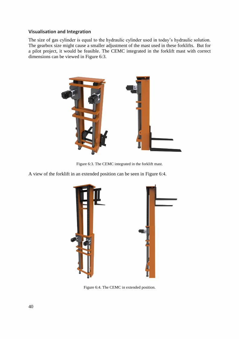
Visualisation and Integration
The size of gas cylinder is equal to the hydraulic cylinder used in today’s hydraulic solution.
The gearbox size might cause a smaller adjustment of the mast used in these forklifts. But for
a pilot project, it would be feasible. The CEMC integrated in the forklift mast with correct
dimensions can be viewed in Figure 6:3.
Figure 6:3. The CEMC integrated in the forklift mast.
A view of the forklift in an extended position can be seen in Figure 6:4.
Figure 6:4. The CEMC in extended position.

41
7 Business Case
The business case of the final concept involves the improvements that implies with a transition
from a hydraulic solution to the CEMC solution. The improvements regards savings in fuel,
emissions and time.
In order to evaluate the energy consumption and productivity, a lift case was designed for
both cases based on their load cases. According to manufacturers, a good approximation for
the time to break-even is after 2-3 years or 100 000 lifting cycles, which is what their
customers commonly accept. Therefore the energy consumption case was calculated for
100 000 lifting cycles.
7.1 Business case: ECH
The business case of the ECH mentions some of the different customer values that can be
translated from the enhanced performance. A comparison is made on the performance of the
hydraulic solution and the CEMC solution.
Lift Case
The loads for the hydraulic ECH were 230 kN when lifting containers, and 70 kN for an
empty lift. All loads for the CEMC ECH were 80 kN. Table 7:1 shows the load case for the
ECH.
Table 7:1. Load case used for energy and productivity calculations of the ECH concept.
Lift height (% of max) Lifting containers Lifting empty Lifting share
50% 25 000 25 000 50%
100% 25 000 25 000 50%
Besides the load case, the respective efficiency of the hydraulic system and the CEMC system
was included. The approximated efficiency of the hydraulic system was set to 70% while the
efficiency of the CEMC system was calculated as the product of the CEMC internal
efficiency, electric motor efficiency and generator efficiency. The CEMC system efficiency
was calculated to 85 %.
To calculate the productivity improvement, the interval time between lifting cycles was
needed. According to the information received from the customer meetings an average
interval for the ECH was approximately three minutes, meaning the time interval of the start
of a lifting cycle to the start of the next lifting cycle.
Performance Case
The ECH has an intense load case with a lift every three minutes, often lifting high and heavy.
In Table 7:2 the improvements in productivity and efficiency made by the CEMC are shown
in relation to the standard hydraulic ECH.

42
Table 7:2. Hydraulics and CEMC energy consumption, lifting time and fuel cost comparisons.
Hydraulic ECH CEMC ECH Improvements and savings
Energy consumed kWh 42411 19493 22918 (54%)
CO2 emission tonnes 23 10 13 (54 %)
Time required hours 943 495 448 (47.5%)
Cost of fuel SEK 112 000 51 000 60 (54%)
The fuel costs saved during the first 100 000 lifts was 60 000 SEK and the time saved was
448 hours. This time is equivalent to 9593 extra cycles (counting 3 minutes between lifting
cycle), and thus having its productivity raised with almost 9.6%. The lowered fuel
consumption of 54 % corresponds to 13 tonnes of reduced CO2 emissions.
Economical savings
The time saved could be translated in employee cost or a number of containers that have been
transported. Considering employee cost, the median salary of harbour workers is 26 800 SEK
(Lönestatistik, 2014), which is equal to 167 SEK per hour. The actual cost, with employment
costs included, is approximately 50% more. This increases the hourly cost of one harbour
worker to 251 SEK. Multiplied with the time saved from lifting, 448 hours, the money
generated from the productivity increase is 112 224 SEK.
Considering the other aspect of productivity, several thousands of containers could have been
moved with the CEMC solution during the time of existing solution with hydraulic cylinders.
The lifting cycles saved are 9593, and the ECH lifting cycle corresponds to two empty
containers, resulting in 19186 containers. These savings are seen in Table 7:3.
Table 7:3. The fuel and time savings of using a CEMC for 100 000 lifting cycles.
Fuel cost savings SEK 159 776
Time savings SEK (employee) 112 224
Containers (lifting 2/cycle) 19186
Total savings SEK 172 000
7.2 Business case: Forklift
The business case of the forklift investigates some of the customer values that are attached
with the enhanced performance. A specific lift case was designed for forklifts for calculating
the energy consumption.

43
Lift Case
The max load of the hydraulic forklift was 110 kN while the CEMC forklift had a max load of
80 kN. The respective minimum loads were 30 kN and 0 kN. The load case designed to
measure the increased productivity and energy efficiency for the forklift can be seen in Table
7:4.
Table 7:4 Load case used for energy and productivity calculations of the forklift concept
Lift height
(% of max)
Lift with max
load
Lift with 50% of
max load
Lift with no load Lifting share
50% 7 000 31 500 31 500 70%
100% 3 000 13 500 13 500 30%
The calculations followed the same logic as in the ECH case. The respective efficiency of the
hydraulic system and the CEMC system was included, as in the ECH case. The efficiencies
were the same; 70% for the hydraulic system and 85% for the CEMC system. Yet again, an
average cycle was needed for the productivity calculation. However, considering forklifts the
load cycle was harder to estimate since forklifts are used in many different industries and
applications.
Performance case
The load case of the forklift is different from that of the ECH, mainly due to many various
lifting heights and loads as previously mentioned. The interval between lifting cycles was six
minutes instead of three according to manufacturers. In Table 7:5 the improvements in
productivity and energy consumption are shown.
Table 7:5. Hydraulics and CEMC energy consumption, lifting time and fuel cost comparisons
Hydraulic forklift CEMC forklift Improvement s and savings
Energy consumed kWh 4316 2052 2264 (52%)
CO2 emissions tonnes 2.3 1.1 1.2 (52 %)
Time required hours 215 112,85 102.1 (47.5%)
Cost of fuel SEK 11369 5406 5963 (52%)
The time required for lifting saved was 47.5 %, which is equivalent to 102 hours
corresponding to 1032 extra cycles. The productivity change ended up at 1%. The energy
saved is 52 % and corresponds to 1.2 tonnes reduced CO2 emissions.

44
Economical savings
The money saved on fuel is 5 963 SEK. Furthermore, the median salary of a forklift driver in
Sweden is 21 600 SEK (Lönestatistik, 2014) which corresponds to 135 SEK per hour. When
considering employment costs this equals to 202 SEK per hour. The time saved is 102 hours
and the economical savings due to improved productivity are 20 675 SEK. The 102 hours
saved corresponds to 1023 lifting cycles, which means this many loads have been gathered
and transported during that time. The savings implicated by having CEMC solution in a 9 ton
forklift is displayed in Table 7:6.
Table 7:6. The economic result of using a CEMC in a forklift for 100 000 lifting cycles.
Fuel cost savings SEK 5 963
Time cost savings SEK 20 675
Number of loads 1023
Total cost savings SEK 26 620
The total savings are in this case 26 620 SEK.
7.3 Benchmarking
There are other parameters to compare than efficiency and energy savings, such as the
capabilities and limitations of different solutions.
Both concepts have a peak force of 80 kN. Therefore benchmarking was conducted on other
solutions delivering the same force. Parameters that were compared were speed and stroke.
The benchmarking included hydraulic cylinders and other EMC solutions form different
manufacturers, the performance parameters can be seen in Table 7:7.
Table 7:7. Benchmarking of CEMC against other solutions EMC’s and hydraulics cylinders
Solution Cascade
EMC
Hydraulic
cylinder PMC EMC
Enerpac Ball
Screw Actuators
Parker
XFC
Force 80 kN 80 kN 80 kN 100 kN 80 kN
Max velocity < 5 m/s <0.5 m/s 0.022 m/s < 0.045 m/s < 0.4 m/s
Stroke -unlimited -unlimited <1.5 m 0.6 m 2 m (1 m
unsupported)
None of the other solutions can compete with the up to 5 m/s velocity of the CEMC.
Furthermore it’s only the CEMC and the hydraulic cylinder that can handle more or less
unlimited strokes. The stroke of the ball screw EMCs are highly limited and the same goes for
the speed. The maximum velocity of the parker XFC reaches 0.4 meter per second which is
the fastest of the three ball screw EMCs, though still slower than hydraulics and about ten
times slower than the CEMC.

45
8 Analysis
The analysis is performed on findings in the frame of reference and the two final concepts.
The concepts are evaluated considering performance, electrification and business case.
There are several aspects that are improved with electromechanics. One of the main
arguments towards electrification is the improved precision and controllability mentioned by
Marek (2013). By having a mechanical break the load will be held at the same height, without
slowly sinking downwards due to oil seeping through vents. The hybrid reach stacker
developed by Konecranes AB (2014) showed that the user comfort was improved along with
performance and reliability.
Further interesting aspect is the predictability of electromechanics which is correlated with
reliability. The lifetime expectancy is easily predicted which allows for strategic and
facilitated planning regarding lifetime and exchange of components, cutting unnecessary and
unexpected maintenance costs.
8.1 ECH
Since the EMC only moves empty containers the main value creating property is at which
speed it can complete each cycle. By replacing the hydraulic cylinders with CEMCs, the limit
in speed caused by the slow hydraulics is greatly raised. The CEMCs can handle speeds up to
5 m/s which would result in a lifting speed of 10 m/s. The new limiting factor becomes the
effect needed from the electric motors. The reason why todays ECHs are lifting with only
about 0.5 m/s is due to the limitation in the hydraulic systems. It is not possible to lift faster
without overheating.
Furthermore, the amount of oil needed for the hydraulic system can be reduced significantly
due to the lifting cylinders that by far, have the largest volume of the cylinders in the system.
This implicates less oil is consumed by the system, cutting reservoir tank volume and
maintenance cost of exchanging and cleaning hydraulic oil.
By allowing electrification of heavier lifts than previously, it is possible that a step towards
all-electric ECHs is made. Even though a diesel powered generator will be used to start with,
the efficiency is higher and the force requirements much lower, resulting in large energy
savings.
The ECH consumes a lot of energy during a lifting cycle compared to a forklift, and the
savings of 54 % corresponds to great amounts of time and fuel saved by the CEMC solution.
The CO2 emissions are also lowered which could be related to a cost concerning emission
permits. Today the average price of CO2 emissions is about 5 euro per ton. Lowering
emissions and fuel consumption is an argument that can be used to create a green, and
environmentally friendly policy for the companies investing in CEMC equipped machines.
When the cycle time is shortened, productivity is increased. The main sell arguments of the
ECH are efficiency and a fast container handling rate, and the CEMC improves these two
most crucial aspects. The 9.5% productivity increase means that a fleet of ten ECHs could be

46
cut to nine still doing the same amount of work, saving the cost of an entire ECH and the
operator.
8.2 Forklift
Regarding the 9 tonnes forklift the performance of the lifting system can be enhanced by the
CEMC. In this category, lifting speed is higher and efficiency of the lifting system is
increased. Higher efficiency means lowered fuel consumption and less CO2 emissions
compared to hydraulics.
Since the 9 tonnes forklift has an electrical powered driveline, the CEMC solution is a
promising solution to implement due to the existing technology, considering both energy
regeneration and battery powered units. The battery time could be improved due to
eliminating the lifting systems own weight and improving the efficiency of the lifts. Battery
driven forklifts with CEMCs could enable electrical forklifts in the heavier classes.
The fully electrified forklift developed by SKF and mentioned by Langer (2002),
demonstrates a good example of battery driven forklifts operating entirely without hydraulic
cylinders. The performance capabilities is however quite low, with regard to the lifting height
and lifting capability. It could be due to the use of ball screw units in this case. A CEMC in
this case could allow higher loads, longer strokes and higher speeds.
Furthermore by using fully electrified forklifts and removing all the oil the risk of leakage is
eliminated. This will greatly improve the hygiene of the machine and guarantee oil and
emission free operating. In some industries where cleanliness is very important, such as
medical, food and paper, the event of oil leaking could have devastating effects such as
ruining merchandise.
The lifting speed is doubled and productivity is increased with about 1%. This is a result of
the fairly low lifting height and the frequency time between lifts. The CEMC has bigger
impact at long strokes and intense lifting frequencies.
8.3 Environmental goals
Taking a step towards becoming independent of petroleum by choosing alternative energy
resources is a vital step considering the diminishing assets which is pointed out by Boulanger
et al. (2011). An important part of this step is electrification of vehicles and machines. Having
components with higher efficiency will reduce the total energy consumption for the
equivalent output, regardless of energy source.
The lifting equipment industry is a dominant user of hydraulics, which means a lot of energy
is wasted because of the low efficiency. It resides a great potential for fuel savings if the
hydraulic cylinders are replaced with mechanical cylinders. This study suggests fuel savings
in both concepts to be close to 50 %. This achievement has been seen in other studies, such as
the one by Jo et al. (2011), who found that the fuel consumption was lowered by 40% by
regenerating energy in a swing body. Konecranes AB (2014) has also developed a hybrid
reach stacker where significant results had been noticed on the fuel savings.

47
Furthermore, WSP Sverige AB (2012) underscores the importance of finding new sectors that
can reduce fuel consumption and reduce CO2 emissions other than within the transport sector,
in order to meet future environmental goals. Obviously, there is great potential within the
heavy lifting equipment industry as well.

48
9 Discussion
Regarding the interval between lifting cycles, both forklift and ECH intervals were validated
by manufacturers. The ECH lifting cycle interval was considered reasonable with intense and
short cycles. The forklift lifting cycle interval was according to manufacturers, very hard to
predict because forklifts are used in various ways. Though six minutes was agreed a good
average for the energy consumption calculations.
The load cases used in both concept solutions are calculated average values and represent a
typical industry setting. In the ECH case, the load cases presented are considered relevant as
the loads and heights are standardised and have a fairly repeated load case. Forklifts however,
are present in many industries and it operates different in different settings. Sometimes it only
moves loads in the horizontal plane rather than in the vertical plane, which means that the
lifting energy consumed would be very similar in the case of hydraulics and in the case of
CEMC’s. Therefore, it should be noted that the forklift energy consumption calculations
represents a very general case.
The forklift CEMC solution drafted in this report, eliminates the own weight of the system,
which means the energy consumed by every small adjustment of raising or lowering the fork
to get it at an accurate position, is practically none. According to manufacturers, these small
adjustments are very common and also require full motor power, which implicates a very
unnecessary waste of energy for a very small movement of the fork.
The protection for the extended rack is a bellow mainly because of its high compressibility.
This is especially desirable in the ECH where the stroke is 9.5 meters. If the compressibility
should be too low too much of the stroke would be consumed by the compressed bellow. The
compression ratio is commonly around 1:15 thus only 0.6 meters of the rack is consumed.
Regeneration of energy is a possibility in both cases. However it depends somewhat on the
properties of the gas cylinder. In the ECH case energy could be regenerated when lifting with
no load or when lowering with load. In the first case, lifting with no load, it’s actually the
energy stored in the gas cylinder that could be used to generating electricity when breaking
the lifting motion. When lowering with load the same forces will be applied and electricity
could be generated when breaking. However in the forklift case the regeneration would work
more traditionally, generating energy when lowering its load.

49
10 Conclusions
The CEMC solutions are in both cases viable in terms of a technical perspective. The
performance is in both cases enhanced regarding speed and efficiency and the integration is
possible with minor modifications of attachments and geometry. This answers the first
research question if CEMC integration is technically viable.
Regarding the second research question if implementing the CEMC system would implicate
improvement towards environmental related goals, many of the results supports this as both
energy and fuel consumption is lowered together with CO2 emissions.
The targeted sector of heavy lifting equipment has a high potential for electrification which
can contribute to reduced emissions and fuel savings and further help reaching environmental
goals. There is a trend of electrification in this particular segment and the ECH concept seems
promising and customers have shown great interest, mainly because of increased productivity
and lowered fuel consumption.
The segment of all-electrical forklifts can be further broadened with CEMC’s allowing lifting
heights and load capabilities to increase. CEMC’s can also provide better regenerative
functions than hydraulics and together with higher efficiency extend operating time of
batteries.
In comparison to other EMC’s on the market none of these are close to the CEMC
considering performance. The CEMC can handle speeds commonly more than ten times faster
than the other solutions. Furthermore, none of these can support long strokes and are at a
maximum able to reach two meter.

50
11 Future Work
Both cases have been shown promising, but there is detailed engineering work left. Aspects
that have not been considered during this project work are suggested.
Only four applications were examined in this study but there are many different equipment
containing actuators of different sorts. Some interesting suggestions found during this study
but has not been presented are: aircraft, mobile cranes and industrial elevators.
A different interesting approach of the CEMC is to develop a customisable concept that is not
designed to fit a certain application, but rather be offered as a product with a range of standard
performances. This is a typical approach by other manufacturers of EMC’s.
It has been proven that using electric drivelines of heavy machinery cuts the energy
consumption. An interesting study would be to investigate the energy savings and potential
productivity increments from replacing all hydraulic cylinders with electromechanical
actuators.
In case of the forklift, it has been mentioned that it has very different industry settings. It
would benefit the development of CEMC forklift to identify a certain industry for
dimensioning and calculating energy consumption. Perhaps where heights and loads are
standardized or in the paper industry where there is a desire for hygienic solutions. The
energy consumption calculations performed in this study provide an indication of how much
can be saved from only the lifting.
To safely operate the machines the center of mass needs to be adjusted to prevent the machine
from tipping. Since the CEMC is heavier than the hydraulic cylinders and have a larger
portion of its mass at the top, the center of mass will be offset. However, no calculations on
this have been made, but effort has been put into minimising the weight of the CEMC system.
The gearboxes for the two CEMCs are only at a conceptual stage and the strength and solidity
of every component needs to be calculated to secure the right lifetime and safety factors. The
gears however, are dimensioned by calculations in MATLAB and have the right sizes and
strengths. The racks are not only exposed to buckling but also deflection, mainly in the ECH
case. What also needs to be reviewed is the moment of inertia of the components to ensure
stability.
There are different possibilities for integration of the CEMC. The easiest way would be to use
the same attachment means as used for the hydraulic cylinders. These attachments could be
installed at the end of the rack and the gas cylinder. Thus integration with no need of
modification could be achieved. This relative simple integration is particular promising in the
ECH where the cylinders are big and are placed on the outside of the mast and with more than
enough space to fit the gearbox. Concerning the forklift, the mast would need a slight
modification to make room for the CEMC. This makes a possible pilot version more
expensive. A possibility that should be investigated is redesigning the forklift mast to
incorporate the CEMC in the mast itself.

51
The lubrication of the gearbox has not been designed. The choices available are fat or oil.
Since the load cases aren’t that intense the lubrication system doesn’t have to be very
complex, rather a nipple where oil or fat can be refilled at a certain interval.

52
12 References
Boulanger, A., Chu, A., Maxx, S., & Waltz, D. (2011). Vehicle Elictrification: Status and
Issues. Proceedings of the IEEE, 99.
Brinkmann, B. (2011). Chapter 2 Operations Systems of Container Terminals: A
Compendious Overview. In J. W. Böse, Handbook of Terminal Planning. Springer.
Cargotec Sweden AB. (2010). Kalmar 5 – 9 tonnes For Operations Beyond the Ordinary.
Cargotec Sweden AB.
Jo, D.-Y., Kwak, S., & Kim, N. (2011). Development of Fuel-Efficient Construction
Equipment. Doosan Infracore Co.
Kanungo, A., & Swan, E. (2008). All Electric Injection Molding Machines: How Much
Energy Can You Save? Energy Systems Laboratory.
Konecranes Lifttrucks AB. (2012). 10 – 80 tons Reachstackers with heart. Konecranes
Lifttrucks AB.
Langer, S. (2002). E-Truck revolutionises the future of industrial vehicles. Evolution.
Marek, J. (2013). Choosing Between Electromechanical and Fluid Power Linear Actuators in
Industrial Systems Design. Thomson Industries, Inc.
Thierrez, A. (2006). An environmental analysis of injection molding equipment.
Massachusetts Institute of Technology.
WSP Sverige AB. (2012). Arbetsmaskiners klimatpåverkan och hur den kan minska. Ett
underlag till 2050-arbetet. Trafikverket.
Web pages
CAT Lift Trucks, (2014). FAQ. Available from: <http://www.catlifttruck.com/FAQ-
materials-handling-equipment> [2014-06-07]
Konecranes AB, (2013). Media Releases. Available from:
<http://www.konecranes.com/resources/media/releases/2013/konecranes-presents-the-worlds-
first-hybrid-reach-stacker >[2014-06-02]
Lönestatistik, (2014). Hamnarbetare löner. Available from:
<http://www.lonestatistik.se/loner.asp/yrke/Hamnarbetare-3063> [2014 -06-06]
Lönestatistik, (2014). Truckförare löner. Available from:
<http://www.lonestatistik.se/loner.asp/yrke/Truckforare-1159> [2014-06-06]

53
Milacron, (2014). Injection Molding Machines. Avialable from:
<http://www.milacron.com/plastics/products-services/injection-molding-machines> [2014-
06-07]
NPTEL, (2014). Hydraulic Actuation Systems. Available from:
<http://nptel.ac.in/courses/Webcourse-
contents/IIT%20Kharagpur/Industrial%20Automation%20control/pdf/L-
26(SM)%20(IA&C)%20((EE)NPTEL).pdf> [2014-06-05]
PMCgroup, (2014). PMC Swedrive, Products. Available from:
http://www.pmcgroup.se/en/About-PMC/Our-Operations/PMC-Swedrive/Products/ [2014-06-
04]


- 1 -
Interview material Appendix A
Cascade EMC development form (Interview material)
Cycle time
Load case

- 2 -
Energy consumption
Electrification
Hydraulic oils

- 3 -
Safety factors
Hydraulics
Model choice for development of an EMC

- 4 -
Questionnare Appendix B
Modell Fyll i modell
Fyll i modell
Antal som tillverkas/år
Tillverkning efter beställning?
Antalet hydrauliska axlar?
Vad kostar det kompletta
hydraulsystemet?
För vilket serviceintervall dimensioneras
modellens komponenter
Lyfthastighet
Vilken lyfthastighet efterfrågas till
framtida versioner
Vilken livstid beräknas modellen ha?
Lastfall och energiförbrukning
Vad är modellens maxlast?
Vad väger lyftanordning utan last?
Dimensioneringslastfall
För vilka lastfall dimensioneras
modellen?
Hur många lyftcykler per år?

- 5 -
Hur ser fördelningen ut mellan högsta och
lägsta lyfthöjd?
Hur varierer maxlyfthastigheten från
ingen till full last?
Genomsnittling cykeltid
Livstid (antal lyft eller driftstimmar)
Standardanvändare
Hur ser lastfallen ut för en
standardanvändare?
Hur ser lastfördelningen ut mellan min-
och maxlast
Hur ser fördelningen ut mellan högsta och
lägsta lyfthöjd?
Hur varierer maxlyfthastigheten från
ingen till full last?
Genomsnittling cykeltid
Hur många lyftcykler görs årligen?
Energiförbrukning
Finns ett specifikt enrgiförbrukningstest?
Ungefärlig energiåtgång för detta test?
Med vilka laster utförst testet?
Total verkningsgrad för modellen

- 6 -
Cylindrar
Krafter (Max / min) / / / /
Slaglängd
Cylinderlängd
Ytterdiameter
Kolvdiameter
Infästningsmodul
Cylinderhastighet
Livstid (antal lyft eller driftstimmar)
Total verkningsgrad för lyftsystemet
Inköpspris hydraulcylindrar
Elektrifiering
Lyftkapacitet
Lyfthöjd
Lyfthastighet
Vad begränsar lyftkapaciteten?
Önskemål
Vilka laster vill man lyfta?

- 7 -
Vilka hastigheter vill man uppnå?
Vilken verkningsgrad vill man uppnå?
Vad begränsar för batteridrift?

- 8 -
Case Study: Reach Stackers Appendix C
The data collected and used for implementation of a cascade gear box is presented here, for
both a 10 tonnes and a 45 tonnes model. Design examples of the gear boxes are presented for
both models, and also designs with new attachment points for the CEMC.
Collected data of reachstackers by different manufacturers.
Unit Hyster Konecranes Liebherr Konecranes
Model - 45-31-16 45-31-16 45-35-18 10-8-5
Max load first row tonnes 45 45 45 10
Lifting height mm 15260 15300 16000 15300
Lifting speed
loaded/unloaded m/s 0,25 /0,48 0.23/0.38 0.3 0.55 / 0.40
Lowering speed m/s 0,46/ 0,45 0.4/0.35 0.5 0.45 / 0.45
CEMC gearbox design example
Cascade gear unit specifications for a 10 ton reachstacker.
Cascade gear box Input 1500 rpm 1000 rpm 500 rpm 200 rpm
Max force kN 365 365 365 365
EMC stroke mm 2400 2400 2400 2400
Cylinder speed m/s 0.4 0.4 0,12 0,12
Peak effect kW 146 146 44 44
Gear ratio (u) - 18 13 22 8
Gear and rack weight(rack) kg 964(487) 771(372) 1100(540) 688(306)
Gear box dimensions HxW mm 1100x650 950x650 1100x700x 900x550
Lifetime years 10 10 10 10
Rack height (module) mm 160(5) 127.8(4.5) 168.3 (5.5) 108(4.5)

- 9 -
Cascade gear unit specifications for a 45 tonnes model.
Cascade gear box Input 200 rpm
Max force kN 1200
EMC stroke mm 2400
Lifting speed (loaded) m/s 0,23
Cylinder speed m/s 0,07
Peak effect kW 84
Gear ratio (u) - 13
Gear and rack weight (rack) kg 4300 (1200)
Gear box dimensions HxW mm 1700x900
Lifetime years 10
Rack height (module) mm 216(9)
New attachment points for both models
By moving the upper attachment points further towards the spreader along the boom closer to
the load, a lower lifting force is required. By changing the lower attachment points, different
strokes can be achieved as well as the force direction.
A code was written in Matlab that calculated the required force for a complete lifting cycle
with each possible composition of boom and body attachment points. About 5700 different
compositions were generated and nine were sorted out representing a specific percentage
position of the boom. Then the configuration requiring the lowest maximum cylinder force
was selected as the optimum. The most optimal position where lowest force required can be
viewed in Figure 12:1.
Figure 12:1. A new position for the EMC which requires a lower lifting force.
The new position for the EMC requires a lifting force of 720 kN for the 45 tonnes model and
a lifting force of 260 kN for the 10 tonnes model. The results of the different positions for 10
tonnes model and 45 tonnes model can be seen in tables.

- 10 -
45 ton reachstacker - calculated data of different attachments for one cylinder/EMC
Percentage of boom allowed % 10 20 30 40 50 60 70 80 90
Attachment body m 2.2 2.9 4.9 6.6 7.0 1.6 2.0 2.4 2.8
Attachment boom m 0.8 1.5 2.3 3.1 3.3 4.8 5.6 6.4 7.2
Max lift force MN 3.15 1.68 1.38 1.23 1.20 1.16 0.97 0.83 0.72
Min lift force MN 2.73 1.45 0.95 0.70 0.66 0.75 0.69 0.64 0.59
Lift force at start MN 3.14 1.67 1.38 1.23 1.20 0.75 0.69 0.65 0.62
Max cylinder speed m/s 0.02 0.04 0.06 0.07 0.07 0.08 0.09 0.10 0.10
Mean cylinder speed m/s 0.01 0.02 0.04 0.05 0.05 0.04 0.05 0.05 0.06
Cylinder length m 2.82 2.82 3.57 4.27 4.44 4.03 4.35 4.69 5.04
Extension ratio n/a 1.28 1.53 1.63 1.68 1.70 1.65 1.69 1.71 1.73
Gear house space m 2.02 1.32 1.34 1.35 1.34 1.41 1.40 1.35 1.36
Cylinder stroke m 0.8 1.5 2.23 2.92 3.1 2.62 2.95 3.34 3.68
Cascade gearbox design example, 45 tonnes reachstacker.
Attachment point (boom,car) m (7.2, 2.8)
Lifting speed (max load) m/s 0.4
Cylinder speed m/s 0.2
Cylinder length m 5,0
Stroke m 3,7
Max force kN 800
Peak effect kW 160
Speed in rpm 200
Gear ratio (u) - 6.25
Gear and rack weight kg 1100 (660)
Gearbox dim HxW mm 1200x700
Lifetime years 10
Rack height (module) mm 126 (7)

- 11 -
10 ton reachstacker - calculated data of different attachments for one cylinder/EMC
Percentage of boom allowed % 10.00 20.00 30.00 40.00 50.00 60.00 70.00 80.00 90.00
Attachment body m 2.10 3.30 4.90 0.80 1.20 1.60 2.00 2.40 2.80
Attachment boom m 0.80 1.50 2.20 3.10 3.90 4.80 5.60 6.40 7.20
Max lifting force MN 1.11 0.66 0.55 0.68 0.52 0.41 0.34 0.29 0.26
Min lifting force MN 0.96 0.51 0.35 0.36 0.31 0.28 0.26 0.24 0.22
Lift force at start MN 1.11 0.66 0.55 0.36 0.31 0.28 0.26 0.25 0.24
Max cylinder speed m/s 0.04 0.07 0.09 0.11 0.12 0.14 0.15 0.16 0.17
Mean cylinder speed m/s 0.02 0.04 0.06 0.05 0.06 0.07 0.08 0.09 0.10
Cylinder length m 2.56 2.84 3.48 3.18 3.48 3.88 4.22 4.57 4.92
Extension ratio n/a 1.31 1.53 1.61 1.55 1.62 1.65 1.68 1.71 1.73
Gear house space m 1.75 1.35 1.36 1.42 1.33 1.35 1.33 1.33 1.35
Cylinder stroke m 0.80 1.49 2.12 1.76 2.15 2.53 2.89 3.23 3.57
Cascade gearbox design example, 10 ton reachstacker
Attachment point (boom, car) m 2.2,4.9 2.2,4.9 7.2,2.8 7.2,2.8 7.2,2.8
Lifting speed (max load) m/s 0,4 0.9 0,4 0,4 1
Cylinder speed m/s 0.09 0.5 0.17 0.17 0,4
Cylinder length m 3.5 3.5 4.9 4.9 4.9
Stroke m 2,1 2,1 3.6 3.6 3.6
Max force kN 550 550 260 260 260
Peak effect kW 50 275 44 44 104
Input speed rpm 200 500 200 500 1000
Gear ratio (u) - 13 6 5 13 10
Gear and (rack) weight kg 1200
(529)
937
(357)
433
(222)
618
(369)
600
(340)
Gearbox dim HxW mm 1200x
700
1000x
600
700x
400
900x
500
900x
500
Lifetime years 10 10 10 10 10
Rack height (module) mm 156
(6)
110
(5.5)
70
(3.5)
112.5
(3.5)
102
(3.5)

- 12 -
Calculation assumptions and possible errors
The force and position of the cylinders has only been calculated in a two dimensional plane,
in reality the cylinders have a tilt in the z plane, which will require the cylinder forces to be
even higher. The boom attachment point is not in line with the attachment points of the
cylinders along the boom, which has been assumed in the calculations. This might also
require higher lifting forces at a lowered boom. The calculations are based on a vertical lift
where the reachstackers boom is extended so that the container has the same x position during
the entire lift. Thus the forces, during a lift, mainly vary due to the changing angle between
boom and cylinder.
The dimensions set are assumed based on product catalogues and geometry. The dimensions
vary among the different manufacturers, but they all have a similar design regarding the
positioning of cylinders.

- 13 -
Case Study: Forklifts Appendix D
The collected data for forklifts are presented below, which were used for drafting design
examples of the gear boxes.
Collected data of forklifts in the range of 1.5-16 tonnes.
Company
CAT CAT Volvo Volvo
Type
Electric Powered Diesel Diesel Diesel
Load Capacity kg 3000 16000 6000 9000
Mast lowered
height mm 2110 2500 2835
Mast extended
height mm 3265
4340 4375
Lifting speed
(loaded/unloaded) m/s 0.36 / 0.55 0.35 / 0.37 0.49 / 0.53 0.43 / 0.47
Lowering speed
(loaded/unloaded) m/s 0.50 / 0.45 0.44 / 0.47 0.5 / 0.45 0.5 / 0.45
CEMC gearbox design example
Load cases and gear box dimensions of the EMC.
Load kg 16000 16000 5000 5000
Max force kN 160 160 50 50
CEMC stroke m 2 2 2 2
Cylinder speed m/s 0.5 0.5 0.5 0.5
Peak effect kW 80 80 25 25
Gear ratio (u) - 2.46 18.51 2.9 10.8
Weight (rack) kg 147 (75) 274(152) 42(26) 61(41)
Gearbox dim HxW mm 500x350 700x450 300x200 400x240
Lifetime years 10 10 10 10
Rack height mm 55 40 40 55

- 14 -
Case Study: Lift Trucks Appendix E
The collected data for container lift trucks are presented below, which were used for drafting
design examples of the gear boxes.
Collected data of container lift trucks.
Type - Empty (ECH) Laden
Load kg 10000 45000
Lifting height mm 2310 - 19070 2300 - 15300
Mast extension (from/to) mm 10490 / 19710 9220 / 17200
Lift/lower speed (loaded) m/s 0.61 / 0.60 0.21 / 0.40
Lift/lower speed (unloaded) m/s 0.68 / 0.60 0.26 / 0.40
CEMC gearbox design example
The container handlers don’t only lift the weight of the container but also the weight of the
mast and spreader. The spreader for laden containers got a weight of 10 tonnes and for the
empty handlers about 5 tonnes.
Cascade gear box design example, container lift truck 10 and 45 tonnes model.
Type - Empty Laden
Force kN 20000 60000
CEMC stroke mm 10000 10000
Cylinder speed m/s 0.5 0.5
Peak effect kW 100 300
Input Speed rpm 3000 2100
Gear ratio (u) - 24 25
Gear and rack weight kg 1400 (1100) 3300 (2500)
Gear box dimensions HxW mm 1000 x 600 1400 x 900
Lifetime years 10 10

- 15 -
Questionnaire Responses Appendix F
Modell Ange modell här Ange modell
här
Antal som tillverkas/år? ca 150 ca 150
Tillverkning efter beställning? Ja Ja
Antalet hydrauliska axlar? 7 st 7st
Vad kostar det kompletta hydraulsystemet för lyftmekanismen?
100000SEK 50000SEK
För vilket serviceintervall dimensioneras modellens komponenter?
1000h 1000h
Vilken livstid beräknas modellen ha?
30000h motsvarande
Lastfall och energiförbrukning
Vad är modellens maxlast? 10ton 9ton
Vad väger lyftanordning utan last?
ca 6 ton ca 2 ton
Standardlastfall
Hur ser standardlastfallet ut? % av lyft % av lyft
0-20 % av maxlast 45 45
20-80 % av maxlast 45 45
80-100 % av maxlast 10 10
Hur ser fördelningen ut mellan lyfthöjder?
% av lyft % av lyft

- 16 -
0-50 % av maxhöjd 70 70
50-100 % av maxhöjd 30 30
Hur varierer maxlyfthastigheten från ingen till full last?
lyfthastighet lyfthastighet
0-20 % av maxlast 0.5m/s 0.45m/s
20-80 % av maxlast 0.48m/s 0.4m/s
80-100 % av maxlast 0.46m/s 0.39m/s
Vilken lyfthastighet vid maxlast efterfrågas till framtida versioner?
0.8m/s 0.6m/s
Energiförbrukning
Hur stor är den totala energiförbrukning vid normaldrift?
ca 10-15l diesel/h ca 7-10kW
Hur stor del av energiförbrukningen utgörs av lyftsystemet?
ca 20% ca 20%
Cylindrar Lyftcylinder Lyftcylinder
Krafter (Max / min) ca230kN/70kN 110kN/30kN
Slaglängd 9500mm 2475
Cylinderlängd 10345mm 3065
Ytterdiameter 140mm 95
Kolvdiameter 110mm 70
Cylinderhastighet 0.25m/s 0.2m/s
Inköpspris hydraulcylindrar ca40000/st ca 8000/st