Embed Size (px)
Citation preview

TNO-IMARESInstitute for Marine Resources and Ecosystem Studies
Mathijs G.D. Smit
Concept development and Literature research
ERMS final-WS Bryne

EIF Drilling Discharges 2
Objectives concept development & literature research
• Concept development: Approaches will be explored and elaborated to serve as a basis for the calculation of EIF(s) for drilling discharges, taking account of relevant regulatory frameworks
• Literature review and data:Surveys through existing literature and field data in order to arrive at the parameters to be used in the EIFcalculations for drilling discharges. Attention will be paid to both physical/chemical processes and exposure/effect assessment. The outcome of the literature survey should define the gaps in data/knowledge to be filled in with laboratory and field work
EIF Drilling Discharges 3
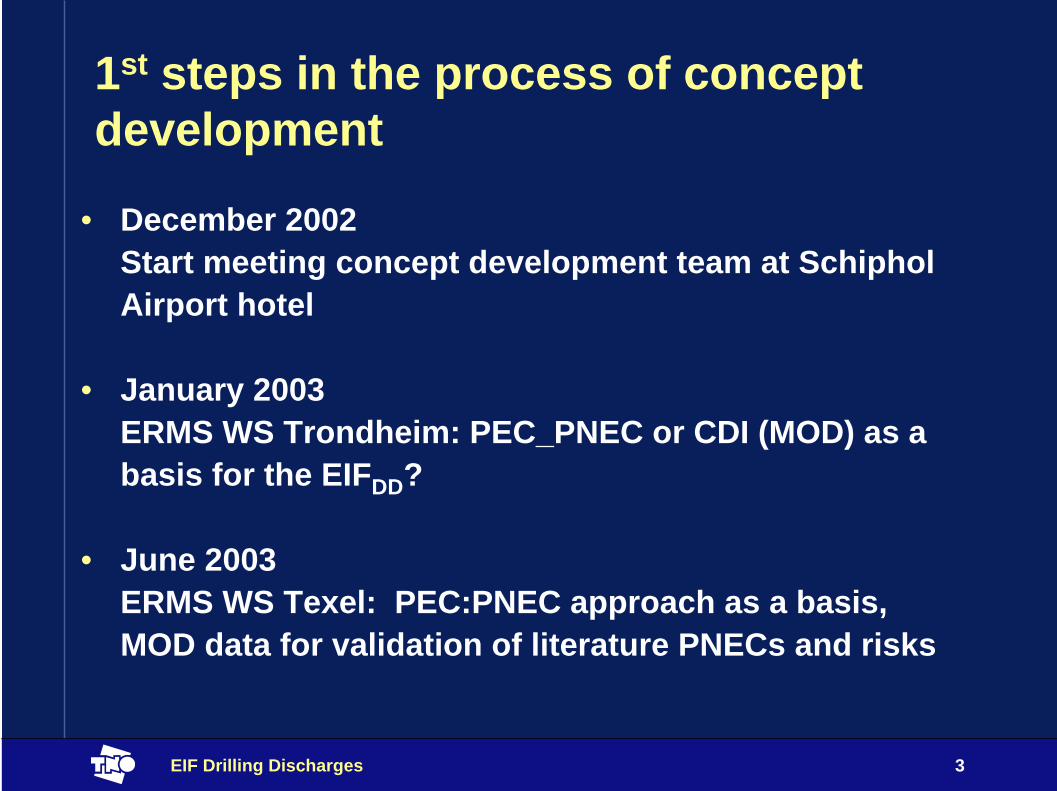
1st steps in the process of concept development
• December 2002Start meeting concept development team at SchipholAirport hotel
• January 2003 ERMS WS Trondheim: PEC_PNEC or CDI (MOD) as a basis for the EIFDD?
• June 2003ERMS WS Texel: PEC:PNEC approach as a basis, MOD data for validation of literature PNECs and risks

EIF Drilling Discharges 4
Internationally agreed principles for risk assessment
1 Hazard identification2 Exposure assessment3 Effect assessment4 Risk assessment5 Validation

EIF Drilling Discharges 5
Exposure modeling
Hazard identification
Biological indices
Risk assessment
2nd stepThresholds based on monitoring data
Field specific
comparison
1st step Thresholds based on most sensitive species
Release information
Literature information
monitoring information
monitoring information
Frame work for the concept development

EIF Drilling Discharges 6
Two Steps in Risk Assessment
• STEP 1:RA following the ‘most sensitive species’approach based on literature information
• STEP 2:RA using thresholds derived from MOD information
• Sediment “validation” (bridge between monitoring and RA)• Water validation; PROOF Validation project (NFR)

EIF Drilling Discharges 7
Elaboration of the concept 1. Hazard identification
• Stressors in the water column• Toxicity• Suspended matter
• Stressors in the sediment• Toxicity• Oxygen depletion• Change in grain size• Burial

EIF Drilling Discharges 8
Elaboration of the concept 2. Exposure assessment
• The exposures of the different stressors will all be assessed by the DREAM/PARTRACK model (ERMS model report no. 18)

EIF Drilling Discharges 9
Elaboration of the concept 2. Exposure assessment
• Exposure in the water column• Chemicals (metals / natural organics / added chemicals) as
prescribed by EU-TGD (toxicity report no 4)• Weighting agents in mud (treated as additional compound
(ERMS report no 4)
• Exposure in the sediment (diagnetic equations)• Chemicals as prescribed by TGD (toxicity report no 4)• Burial expressed as thickness of the added layer (model report no 18)• Change in median grain size upper 3cm (model report no 18)• Change in oxygen content upper 10 cm (model report no 18)

EIF Drilling Discharges 10
Definition of the PECs for toxicants-2
0
2
4
6
8
10
120 1 2 3 4 5 6 7 8 9
toxicant concentration (mg/kg)
dept
h (c
m)
toxicant concentrationmixing depth
PEC = average concentration over upper 3 centimeter

EIF Drilling Discharges 11
Definition of the PEC for burial-4
-2
0
2
4
6
8
10
12
deposited layer thickness
dept
h (c
m)
layer thickness at time = 1layer thickness at time = 2layer thickness at time = 3layer thickness at time = 4 mixing depth
PEC = momentary layer thicknessPEC burial = layer thickness cumulative over time

EIF Drilling Discharges 12
Definition of the PEC for change in grain size
-2
0
2
4
6
8
10
120 1 2 3 4 5 6 7 8 9
median grain size (um)
dept
h
changed median grainsizeoriginal grain sizemixing depth
PEC = percentage of change in average median grain size over upper 3 centimeter

EIF Drilling Discharges 13
Definition of the PEC for change in integrated oxygen concentration over RPD (Redox Potential Discontinuity)
-2
0
2
4
6
8
10
120 1 2 3 4 5 6 7 8 9
oxygen concentration (mg/kg)
dept
h
normal oxygen profilereduced oxygen profileRDP depth
PEC = reduction of total oxygenover RDP-layer

EIF Drilling Discharges 14
Elaboration of the concept 3. Effect assessment
• Effects in the water column• PNEC for chemicals (metals / natural organics / added chemicals)
(ERMS toxicity report no 4)• PNEC suspended matter from SSDs for weighting material in muds)
(ERMS suspended matter report no 6)
• Effects in the sediment• PNEC for chemicals (ERMS toxicity report no 4)• PNEC for burial from an SSD (ERMS non-toxic stressors report no 9)• PNEC for grain size changes from an SSD based on monitoring data
(ERMS non-toxic stressors report no 9)• PNEC for oxygen depletion (ERMS non-toxic stressors report no 9)
PNECs for non toxic stressors are to be discussed later today

EIF Drilling Discharges 15
Elaboration of the concept4. Risk assessment
• Risk assessment includes comparison of exposure and effect levels
• Combination of PEC:PNEC approach and an estimate for the variation in sensitivity between species (probabilistic risk assessment like in the EIFPW)
• For each stressor the PAF is calculated (Potentially Affected Fraction of Species)
• The PAFs for different stressors are combined in a msPAF (multi stressor PAF) assuming additivity
• The EIF is a function of the sediment area (or water volume) where msPAF > 5%

EIF Drilling Discharges 16
From PEC to risk for toxicants in water• Calculate PECwater for all components• Compare PECwater with PNECwater• Translate PEC:PNEC ratio to % risk (PAF) using SSDs
• Combine risks (PAFs) of different toxicants by adding probabilities (same as for produced water EIF)
• Calculate area with msPAF > 5% for the mixture of components
• Result:Water volume with msPAF > 5% for exposure to mixture of toxic substances

EIF Drilling Discharges 17
From PEC to risk for particulate matter in water
• Calculate PECwater for weighting agent• Compare PECwater with PNECwater• Translate PEC:PNEC ratio to % risk (PAF) using SSDs
• Combine risks (PAFs) of weighting material and toxicants by adding probabilities (same as for produced water EIF)
• Calculate volume with msPAF > 5% for the mixture
• Result:Water volume with msPAF > 5% for exposure to mixture
EIF Drilling Discharges 18
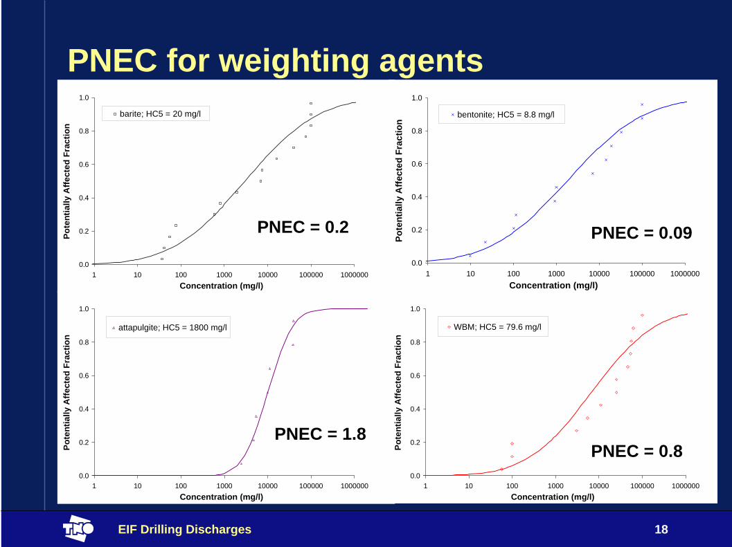
PNEC for weighting agents
0.0
0.2
0.4
0.6
0.8
1.0
1 10 100 1000 10000 100000 1000000Concentration (mg/l)
Pote
ntia
lly A
ffect
ed F
ract
ion
barite; HC5 = 20 mg/l
0.0
0.2
0.4
0.6
0.8
1.0
1 10 100 1000 10000 100000 1000000Concentration (mg/l)
Pote
ntia
lly A
ffect
ed F
ract
ion
bentonite; HC5 = 8.8 mg/l
0.0
0.2
0.4
0.6
0.8
1.0
1 10 100 1000 10000 100000 1000000Concentration (mg/l)
Pote
ntia
lly A
ffect
ed F
ract
ion
attapulgite; HC5 = 1800 mg/l
0.0
0.2
0.4
0.6
0.8
1.0
1 10 100 1000 10000 100000 1000000Concentration (mg/l)
Pote
ntia
lly A
ffect
ed F
ract
ion
WBM; HC5 = 79.6 mg/l
PNEC = 0.2 PNEC = 0.09
PNEC = 1.8PNEC = 0.8
EIF Drilling Discharges 19
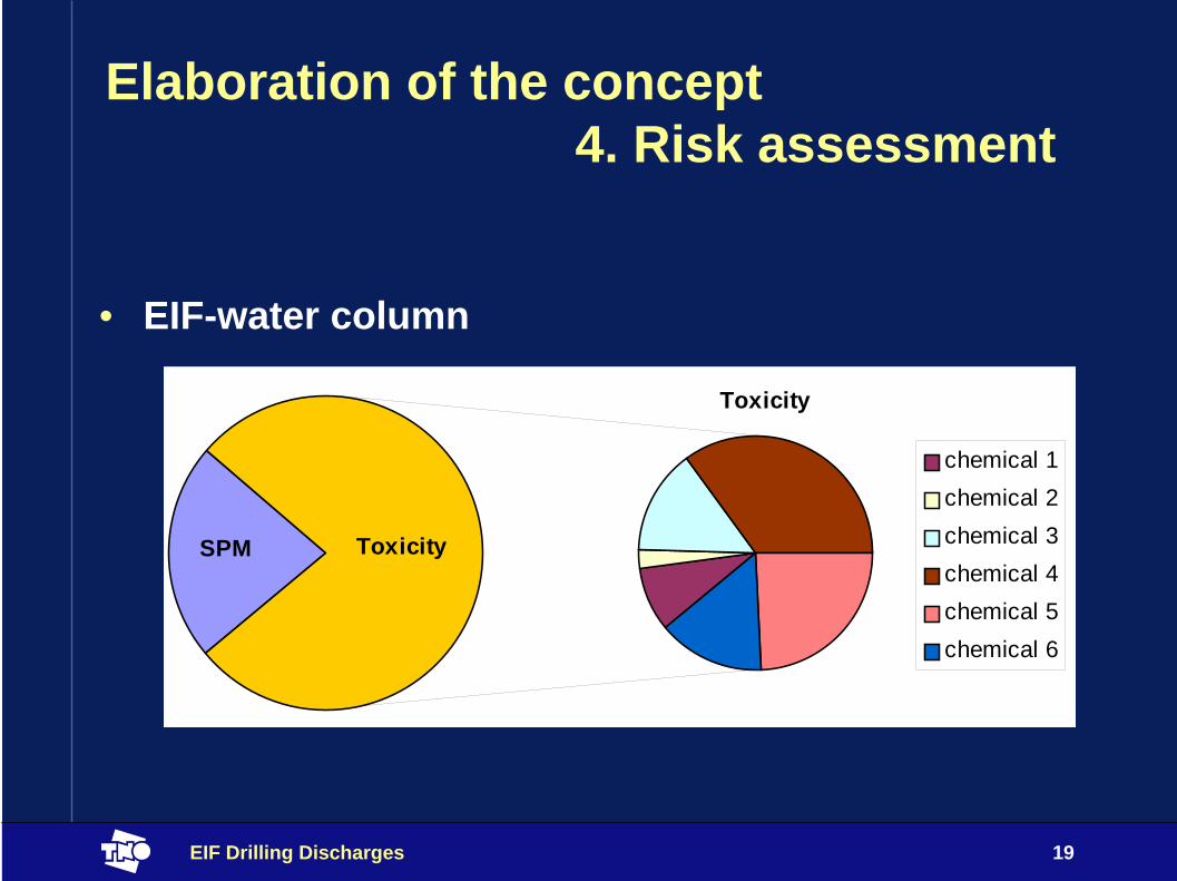
Elaboration of the concept4. Risk assessment
• EIF-water column
chemical 1chemical 2chemical 3chemical 4chemical 5chemical 6
SPM Toxicity
Toxicity

EIF Drilling Discharges 20
From PEC to risk for toxicants in sediment• Calculate PECsediment for all components• Compare PECsediment with PNECsediment• Translate PEC:PNEC ratio to % risk (PAF) using sediment SSDs
(variation in species sensitivity for aquatic species = variation in species sensitivity for sediment biota, when the Equilibrium partitioning is assumed, Posthuma et al., 2002)
• Combine risks (PAFs) of different toxicants by adding probabilities (same as for produced water EIF)
• Calculate area with msPAF > 5% for the mixture of components
• Result:Sediment Surface Area with msPAF > 5% for exposure to mixture of toxic substances

EIF Drilling Discharges 21
From PEC to risk for burial• Calculate thickness of deposited layer • zero–level is defined at the beginning of the drilling
process• PEC = layer thickness above this zero-level• Compare thickness with thickness threshold (0.65 cm)• Present the area where this threshold is exceeded
(PAF > 5%)
• Result:Sediment surface area with PAF > 5% (PEC:PNEC > 1) for exposure to sedimentation
EIF Drilling Discharges 22
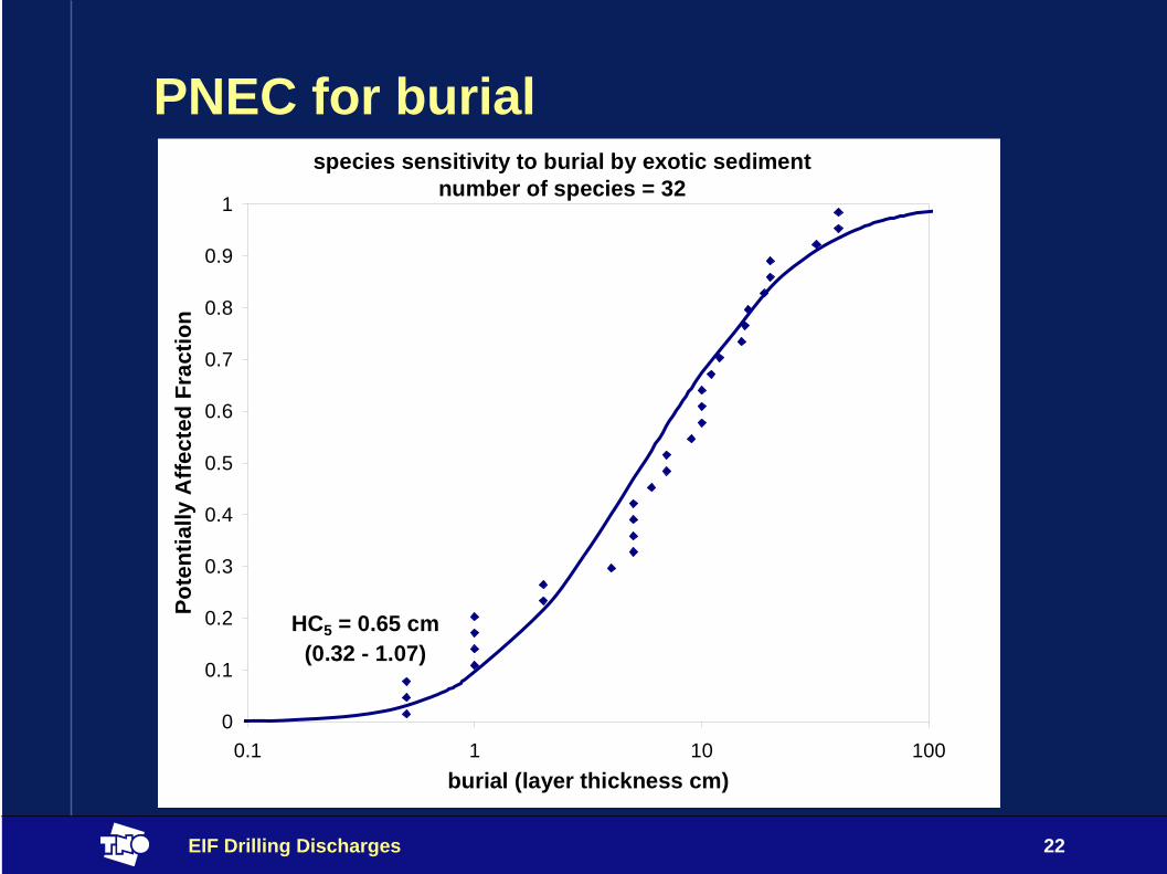
PNEC for burialspecies sensitivity to burial by exotic sediment
number of species = 32
0
0.1
0.2
0.3
0.4
0.5
0.6
0.7
0.8
0.9
1
0.1 1 10 100burial (layer thickness cm)
Pote
ntia
lly A
ffect
ed F
ract
ion
HC5 = 0.65 cm(0.32 - 1.07)

EIF Drilling Discharges 23
From PEC to risk for changes in grain size
• Calculate change in median grain size (%)• Compare change in grain size with maximum
allowable change in grain size (threshold = 52.7 µm)• Calculate area where this threshold is exceeded
(PEC:PNEC > 1, PAF > 5%)
• Result:Sediment Area with PAF > 5% (PEC:PNEC > 1) caused by altered grain size
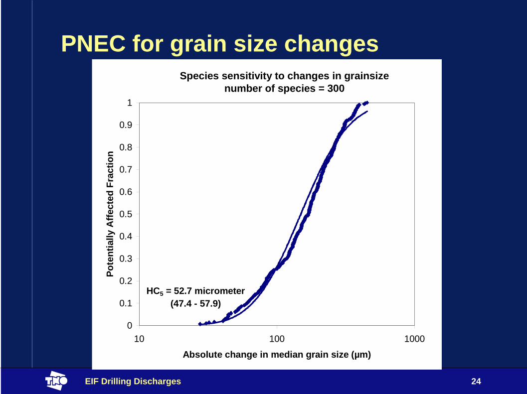
EIF Drilling Discharges 24
PNEC for grain size changesSpecies sensitivity to changes in grainsize
number of species = 300
0
0.1
0.2
0.3
0.4
0.5
0.6
0.7
0.8
0.9
1
10 100 1000
Absolute change in median grain size (µm)
Pote
ntia
lly A
ffect
ed F
ract
ion
HC5 = 52.7 micrometer(47.4 - 57.9)

EIF Drilling Discharges 25
From PEC to risk for change in oxygen• Calculate integrated oxygen conc. in normal (undisturbed)
situation
• Calculate integrated oxygen conc. in disturbed situation
• Allowable change in oxygen concentration is 20%
• Calculate the area where the change in integrated oxygen conc exceeds this level.
• Sediment Area with PAF > 5% (PEC:PNEC > 1) for exposure to reduced oxygen concentrations

EIF Drilling Discharges 26
PNEC for oxygen depletionPredicted community changes related to oxygen depletion
0.0
0.1
0.2
0.3
0.4
0.5
0.6
0.7
0.8
0.9
1.0
10% 100%reduction of the integrated oxygen concentration
Prob
abili
ty o
f str
uctu
ral c
hang
es
HC5 = 20%

EIF Drilling Discharges 27
Chemical stress (toxicity)
Oxygen depletion
Change in grain size
Burial
Area at Risk = area where Integrated risk > 5%
INTEGRATED RISK > 5%

EIF Drilling Discharges 28
EIF Sediment = Area at Risk / 100m x100m
chemical 1chemical 2chemical 3chemical 4chemical 5chemical 6
toxicity
burial
oxygendepletion
change grain size Contribution to risk
based on probabilitiesContribution to risk based on surface with PEC:PNEC>1

EIF Drilling Discharges 29
Elaboration of the concept4. Risk assessment
Time development of the EIF sediment
0
0.5
1
1.5
2
2.5
3
3.5
4
4.5
0 1 2 4 8 16 32 24 32 64 128
256
512
1024
2048
4096
time in days
EIF
-Sed
imen
t
GrainsizeOxygenToxicityBurial

EIF Drilling Discharges 30
Elaboration of the concept5. Validation
• Validation of PNECs• Moving window approach (ERMS report no 13 &14)• UiO approach (ERMS report 15)
• Validation of risks• Risk areas vs disturbed areas

EIF Drilling Discharges 31
Comments V. Forbes to the concept (1)
• The proposed procedures are broadly consistent with the European Union practices for risk assessment of new and existing chemicals, which should facilitate acceptance of the overall approach
• The EIF concept, by relating levels of exposure to drilling-based stressors to likelihood of effects in biota, provides a scientifically sound basis for risk assessment and risk management
• The approach described in the TNO report provides an important step toward addressing complex multi-stressor risks in a scientifically sound way

EIF Drilling Discharges 32
Comments V. Forbes to the concept (2)
• The present report (v01/06) does not provide enough detail to allow the validity of the predicted exposure concentrations to be evaluated. The extent to which the fate model has been validated in the field is not reported
• Although different aspects of the exposure and effects assessments have apparently been addressed in detail in other reports, further details are needed in this TNO report to allow proper evaluation and understanding of the overall approach
EIF Drilling Discharges 33
Comments V. Forbes to the concept (3)• The effects assessment is based on the construction SSDs.
Although a widely accepted approach in chemical risk assessment, the assumptions and limitations of the resulting output values should be more explicitly recognized. The interpretation of SSD results needs particular care. More attention should be given to the uncertainties associated with the SSD output (conf. lim)
• It is important to note that the method for combining risk measures proposed in the report assumes that the severity of effects used to construct the SSDs for different stressors is similar across all stressors being combined (in other words that the relationship between PAF and actual risk is similar across stressors). This assumption should be made more explicit

EIF Drilling Discharges 34
Comments V. Forbes to the concept (4)
• Validation of the EIFDD using field monitoring data will be an important step in its further development, and on the basis of the present TNO report, it would seem that more attention needs to be given to this step
• There are a number of areas in which additional data, testing and/or field monitoring could be used to further refine the EIFDD approach, and inclusion of a prioritized list of these could be a useful addition to the report

EIF Drilling Discharges 35
Recommendations V.Forbes to the concept (1)• The EIF, by combining the essential elements of hazard
and exposure, is a good basis for risk assessment of drilling discharges. It is recommended that, as much as possible, the approach attempts to be consistent with EU guidance for chemical risk assessment
• Although many of the detailed procedures for PEC and PNEC estimation have been described elsewhere, the present report should include enough information so that the elements going into the EIF calculation can be evaluated without reference to these other reports.

EIF Drilling Discharges 36
Recommendations V.Forbes to the concept (2)• In deriving SSDs, a number of decisions have to be
made, i.e., on the shape of the distribution to fit, on the type of data going into the distribution, on the percentile that will be used as an effects threshold (i.e., the HCx), and on the confidence limits around the HCx. These decisions should be made as consistently and transparently as possible
• Care needs to be taken in extrapolating toxicity data from water column exposures to sediment exposures. In the first instance an equilibrium partitioning approach may be used, but the assumptions and limitations of this method should be clearly articulated

EIF Drilling Discharges 37
Recommendations V.Forbes to the concept (3)• It is recommended to keep the EIFwater and
EIFsediment as separate elements of risk as suggested in the report. Both because the time scale of effects differs and the units of the measures differ, it does not seem that there is any added value in combining these into a single EIF
• As the EIFDD is defined (the volume or area over which the PAF exceeds 5%), it neglects differences in the relative magnitudes of impacts. An improvement would be to map the actual PAF for each stressor in space.

EIF Drilling Discharges 38
Recommendations V.Forbes to the concept (4)• Further clarification is needed on the validation step.
• The EIF for drilling discharges assumes that the effects of the different stressors are additive. It should be considered the extent to which the additivity assumption is likely to be ‘worst-case’, whether there are situations for which it may lead to underestimates of risk, and whether there could be a way to refine the assumption.
• Given that the number of stressors to be considered in the EIFDD is relatively small, it is recommended that effort be devoted to collecting further test data on relevant marine species so that uncertainties associated with the SSDs can be reduced

EIF Drilling Discharges 39
Actions towards finalisation• Final report is prepared 01/05/06 by TNO
• Manuscript preparation concept development