Embed Size (px)
Citation preview
Concentric Dual-tubing Steam Injection: A New
Model for Predicting Steam Pressure in the
Annulus
Hao Gu, Linsong Cheng, Shijun Huang, Shuang Ai, and Shaolei Wei
Department of Petroleum Engineering, China University of Petroleum, Beijing, China
Email: [email protected], {guhao110110, fengyun7407, aishuang4415, leisurewin}@163.com
Abstract—It is not always easy to accurately predict
bottomhole steam pressure, temperature and quality when
we design concentric dual-tubing steam injection schemes
due to the complexity of two-phase flow in the annulus, also,
previous methods for estimating pressure gradient in annuli
are time-consuming. In this study, a new model is
established based on mass and energy balances to calculate
steam pressure in the annulus. A more rigorous
thermodynamic behavior of steam/water mixture is also
taken into account. More importantly, one-to-one
correspondence between pressure gradient and temperature
gradient of saturated steam is reasonably developed and
applied in further derivation. The results indicate that the
proposed model is more accurate and convenient in
predicting steam pressure than previous methods. Moreover,
the steam pressure in the inner tubing drops faster than that
of in the annulus even the wellhead mass flow rate of the
former is lower. The variation law of steam quality in the
inner tubing is different from that of in the annulus,
depending on the net heat losses of mixture fluid in each
tubing.
Index Terms—new model, steam pressure, concentric dual-
tubing, annulus, heat transfer
I. INTRODUCTION
Heavy oil reserves are widely distributed in the world
and they play an important role in today’s energy supplies
[1]. However, it is not always easy to efficiently develop
high-viscosity oil due to low mobility under initial
formation temperature. At present, thermal recovery
methods, especially for steam injection techniques, are
extensively used in the process of heavy oil production.
Injecting steam into wellbore would inevitably result in
heat exchange between the wellbore fluid and its
surrounding formation [2]. In addition, the steam pressure,
temperature and quality would change as fluid flows
down the wellbore. Therefore, predicting wellbore heat
losses and bottomhole steam properties are two major
tasks when we design steam injection projects. However,
there are always many difficulties in designing concentric
dual-tubing steam injection schemes because two-phase
flow in the annulus is much more complex than that of in
pipes, so is the estimation of pressure gradient.
Manuscript received December 4, 2013; revised April 15, 2014.
The calculation methods for pressure gradient in annuli
can be divided into two categories: empirical correlations
and mechanistic models [3]. Many researchers have
established different mechanistic models for two-phase
flow in annuli based on flow-patterns, such as Caetano [4]
(1985) model, Antonio et al. [5] (2002) model and Yu et
al. [3] model (2010). However, the definitions of flow
patterns, the transition criteria and the process of
calculating flow-parameters are very complicated and
time-consuming. Griston et al. [6] treated the annuli as
pipes on the bases of hydraulic diameter concept, while it
is just an approximation and will be discussed later.
For heat transfer between the wellbore fluid and its
surrounding formation, Ramey [7] proposed the
expression of fluid temperature in wellbores. His work
laid the foundation for later researchers though he only
considered single phase (ideal gas and incompressible
liquid) flow. Satter [8] took into account the effect of
condensation and presented a method for calculating
steam quality, but he ignored frictional losses and kinetic
energy effects. Holst and Flock [9] studied the effect of
friction on wellbore heat losses. Willhite [10] explicitly
analyzed three mechanisms (conduction, natural
convection and radiation) of heat transfer in the wellbores
and suggested a method for determining over-all heat
transfer coefficient.
Recently, more and more researchers combined heat
transfer model with two-phase flow model , such as
Fontanilla and Aziz [11] (1982), Alves et al.[12](1992),
Hasan . [13]-[16](1994,2007,2009),Bahonar et al.
[17](2010) and Mahdy et al.[18](2012).However, these
models are all about sing-tubing steam injection. Barua
[19] and Hight [20] mentioned concentric dual-tubing
steam injection, but neither set up concrete mathematical
models.
In this work, we propose a new model which is more
accurate and convenient to predict steam pressure in the
annulus. In addition, the characteristics of heat transfer in
concentric dual-tubing are also analyzed in detail.
II. MODELING FLUID PRESSURE
Fig. 1 shows the schematic diagram of concentric dual-
tubing steam injection well over the differential length of
zd .After steam reaches the wellhead along surface
245
Journal of Industrial and Intelligent Information Vol. 2, No. 4, December 2014
©2014 Engineering and Technology Publishingdoi: 10.12720/jiii.2.4.245-251
et al

pipelines, it would be simultaneously enter into the inner
tubing and the annulus between the inner and outer tubing.
Figure 1. Concentric dual-tubing steam injection well.
A. Pressure Gradient in the Inner Tubing
For two-phase flow in the inner tubing, the pressure
calculation model proposed by Beggs and Brill [21] is
adopted. The governing equations for mixture fluid over a
differential length of zd yield to the following equations:
Mass balance equation
0ininin
zz
W (1)
Momentum balance equation
zD
gz
p
d
d
2sin
d
d ininin
in
2
ininin
in (2)
where inW and in are the mass flow rate and the velocity
of mixture fluid in the inner tubing, respectively; in and
inp are the density and the pressure of mixture fluid,
respectively; is the two-phase friction factor; inD is the
diameter of inner tubing; g is the gravitational
acceleration; is the well angle from horizontal. The
third term of the right side in (2) can be given by
z
p
pz d
d
d
d in
in
sginininininin
(3)
where sgin is the superficial velocity of gas phase in the
inner tubing.
Substituting (3) into (2), an expression for the pressure
gradient in the inner tubing can be obtained,
insgininin
in
2
ininin
in
/1
2sin
d
d
p
Dg
z
p
(4)
B. Pressure Gradient in the Annulus
Griston et al. [6] treated the annuli as pipes based on
hydraulic diameter concept, however, hydraulic diameter
is not always a suitable representative characteristic
dimension for two-phase flow in the annulus [4]. In this
study, a new semi-analytical model for estimating
pressure gradient in the annulus is formulated.
The heat changes of mixture fluid in the annulus result
from two parts: heat losses to the formation, heat losses to
the inner tubing or heat absorption from the inner tubing.
A general energy balance on the fluid can be written as
sin2d
d
d
d
d
d
d
d12
outoutinout
out
gv
zz
h
z
Q
z
Q
W
(5)
where outW and out are the mass flow rate and the
velocity of mixture fluid in the outer tubing,
respectively; outh are the specific enthalpy of mixture
fluid; zQ d/d out is the rate of heat transfer from the
annulus to the formation; zQ d/d in is the rate of heat
transfer from the inner tubing to the annulus, but if the
value of zQ d/d in is negative, it indicates the annulus
absorbs heat from the inner tubing.
In (5), the kinetic energy change for per unit mass of
mixture fluid over the differential length of zd can be
similarly obtained from (3)
z
p
pz
v
z d
d
d
d
2d
d out
out
sgoutoutoutout
2
out
(6)
where sgout is the superficial velocity of gas phase in the
annulus.
Using basic thermodynamic principles, the enthalpy
gradient can be written in terms of the temperature and
pressure gradients [12]:
z
pCC
z
TC
z
p
p
h
z
T
T
h
z
h
Tp
d
d
d
d
d
d
d
d
d
d
outpmJm
outpm
out
out
outout
out
outout
(7)
where pmC is the heat capacity of mixture fluid at
constant pressure; JmC is the Joule-Thompson coefficient.
Substituting (6) and (7) into (5)yields,
sindz
d
d
d
d
d
d
d
d
d1
out
out
sgoutoutpm
outpmJm
inout
out
gp
pz
TC
z
pCC
z
Q
z
Q
W
(8)
The relationship between temperature gradient and
pressure gradient can be further created. Ejiogu and Fiori
[22], Tortlke and Farouq Ali [23] proposed different
correlations between temperature and pressure of
saturated steam based on steam table. In this study, the
Tortlke and Farouq Ali’s correlation is adopted due to its
high accuracy and validation throughout almost the entire
steam-saturation envelope, which is given by
432ln019017.0ln101806.0ln
38075.1ln085.14034.280
ppp
ppfT
(9)
246
Journal of Industrial and Intelligent Information Vol. 2, No. 4, December 2014
©2014 Engineering and Technology Publishing
The relationship between temperature gradient and
pressure gradient of saturated steam can be expressed as
z
p
p
pf
z
T
d
d
d
d
d
d (10)
Substituting (10) into (8) reduces to the pressure
gradient in the annulus
out
sgout
pm
out
outpmJm
inout
outout
d
d
sind
d
d
d1
d
d
pC
p
pfCC
gz
Q
z
Q
W
z
p
(11)
In (11), the heat capacity and the Joule-Thompson
coefficient of two-phase flow system can be estimated by
referring to the method suggested by Alves et al. [12].
Therefore, it is easy to calculate the pressure drop in the
annulus without using mechanistic models or empirical
correlations, which depend on complicated flow-patterns
or approximate treatment. But before (11) can be used, it
is necessary to estimate zQ d/d in and zQ d/d out
.
III. MODELING WELLBORE HEAT TRANSFER
As fluid flows both in the inner tubing and in the
annulus, heat transmission can be separated into three
parts: (a).Heat exchange between the fluid in the inner
tubing and in the annulus. (b).Heat transfer from the fluid
in the annulus to the cement sheath. (c).Heat transfer in
the formation. If the wellhead injection conditions remain
constant, heat transfer inside the wellbore can be assumed
steady-state while heat transfer in the formation can be
assumed transient, Holst and Flock [9] discussed the
assumption in detail.
A. Heat Exchange between the Fluid in the Inner
Tubing and in the Annulus
There would be heat exchange between the fluid in the
inner tubing and in the annulus if the fluid temperature is
not equal. The rate of heat flow over the differential
length of zd can be given based on Fourier law
)(2d
doutintoto
in TTUrz
Q (12)
where tor is the outside radius of inner tubing; inT and
outT are the temperature of fluid in the inner tubing and in
the annulus, respectively; toU is the over-all heat transfer
coefficient for inner tubing, which can be written as
follows:
1
ftoti
to
tub
to
tifti
toto
1ln
hr
rr
rh
rU
(13)
where, ftih and ftoh are the forced-convection heat transfer
coefficient on inside and outside of inner tubing,
respectively; tub is the thermal conductivity of tubing
wall; tir is the inside radius of inner tubing.
Because the forced-convection heat transfer coefficient
( ftih and ftoh ) and the thermal conductivity of tubing wall
( tub ) are very high, the rate of heat exchange between
the fluid in the inner tubing and in the annulus would be
very fast even the temperature difference is small.
B. Heat Transfer from the Fluid in the Annulus to the
Cement Sheath
Similarly, for steady-state heat transfer from the fluid
in the annulus to the cement sheath, the rate of heat flow
can be expressed as
)(2d
dhoutdodo
out TTUrz
Q (14)
where, dor is the outside radius of outer tubing; hT is the
wellbore/formation interface temperature ; doU is the
over-all heat transfer coefficient between the outer tubing
and the cement sheath. Willhite [10] proposed the method
for calculating doU , which can be given by
1
co
h
cem
do
ci
co
cas
do
rcdi
do
tub
do
difdi
do
do
lnln
1ln
r
rr
r
rr
hhr
rr
rh
r
U
(15)
where, fdih is the forced-convection heat transfer
coefficient on inside of outer tubing; dir is the inside
radius of outer tubing; cir and cor are the inside radius and
outside radius of casing, respectively; hr is the outside
radius of the wellbore; cas and cem are the thermal
conductivity of casing and cement, respectively; ch and
rh are the convective heat transfer coefficient and the
radiative heat transfer coefficient, respectively, which can
also be estimated by referring to the correlations
suggested by Willhite [10].
Also, because fdih , tub and cas are large compared
with other terms in (15), the expression of doU can be
reduced to (16)
1
co
h
cem
do
rc
do ln1
r
rr
hhU
(16)
C. Heat Transfer in the Formation
For the transient heat transfer in the formation, the rate
of heat flow is the function of injection time and
temperature difference, the general expression is
tf
TT
z
Q eiheout 2
d
d
(17)
where, e is the thermal conductivity of the formation;
eiT is the initial temperature of the formation at any given
247
Journal of Industrial and Intelligent Information Vol. 2, No. 4, December 2014
©2014 Engineering and Technology Publishing
depth, sin0ei azTT ,0T is the surface temperature of
the formation, a is the geothermal gradient; )(tf is the
transient heat-conduction time function. Ramey [7],
[24] and Hasan et al. [25] proposed different
empirical expressions, however, Hasan et al. method is
adopted due to its accuracy, which is given by
5.1)6.0
1(ln5.04063.0)(
5.1)3.01(1281.1)(
D
D
D
DDD
tf
tf
,
, (18)
Combing (14), and (17) yields,
edodo
dodoouteieh
)(
)(
tfUr
tfUrTTT (19)
eiout
edodo
edodoout -)(
2
d
dTT
tfUr
Ur
z
Q
(20)
The method for predicting steam quality is presented in
Ref. [26]. Equations (4), (11), (12), (20) and steam
quality model need to be coupled and solved iteratively
for each segment.
IV. RESULTS AND DISCUSSIONS
A. Comparison with Field Data
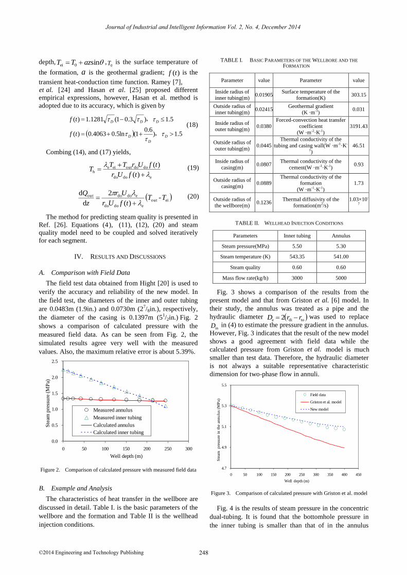
The field test data obtained from Hight [20] is used to
verify the accuracy and reliability of the new model. In
the field test, the diameters of the inner and outer tubing
are 0.0483m (1.9in.) and 0.0730m (27/8in.), respectively,
the diameter of the casing is 0.1397m (51/2in.) Fig. 2
shows a comparison of calculated pressure with the
measured field data. As can be seen from Fig. 2, the
simulated results agree very well with the measured
values. Also, the maximum relative error is about 5.39%.
0.0
0.5
1.0
1.5
2.0
2.5
0 50 100 150 200 250 300
Measured annulus
Measured inner tubing
Calculated annulus
Calculated inner tubing
Ste
am p
ress
ure
(M
Pa)
Well depth (m)
Figure 2. Comparison of calculated pressure with measured field data
B. Example and Analysis
The characteristics of heat transfer in the wellbore are
discussed in detail. Table I. is the basic parameters of the
wellbore and the formation and Table II is the wellhead
injection conditions.
TABLE I. BASIC PARAMETERS OF THE WELLBORE AND THE
FORMATION
Parameter value Parameter value
Inside radius of inner tubing(m)
0.01905 Surface temperature of the
formation(K) 303.15
Outside radius of inner tubing(m)
0.02415 Geothermal gradient
(K ·m-1) 0.031
Inside radius of outer tubing(m)
0.0380 Forced-convection heat transfer
coefficient
(W ·m-2·K-1)
3191.43
Outside radius of
outer tubing(m) 0.0445
Thermal conductivity of the
tubing and casing wall(W ·m-1·K-
1) 46.51
Inside radius of
casing(m) 0.0807
Thermal conductivity of the
cement(W ·m-1·K-1) 0.93
Outside radius of
casing(m) 0.0889
Thermal conductivity of the formation
(W ·m-1·K-1)
1.73
Outside radius of the wellbore(m)
0.1236 Thermal diffusivity of the
formation(m2/s) 1.03×10-
7
TABLE II. WELLHEAD INJECTION CONDITIONS
Parameters Inner tubing Annulus
Steam pressure(MPa) 5.50 5.30
Steam temperature (K) 543.35 541.00
Steam quality 0.60 0.60
Mass flow rate(kg/h) 3000 5000
Fig. 3 shows a comparison of the results from the
present model and that from Griston et al. [6] model. In
their study, the annulus was treated as a pipe and the
hydraulic diameter todie 2 rrD was used to replace
inD in (4) to estimate the pressure gradient in the annulus.
However, Fig. 3 indicates that the result of the new model
shows a good agreement with field data while the
calculated pressure from Griston model is much
smaller than test data. Therefore, the hydraulic diameter
is not always a suitable representative characteristic
dimension for two-phase flow in annuli.
4.7
4.9
5.1
5.3
5.5
0 50 100 150 200 250 300 350 400 450
Field data
Griston et al. model
New model
Ste
am
pre
ssu
re i
n t
he
ann
ulu
s (M
Pa)
Well depth (m)
Figure 3. Comparison of calculated pressure with Griston et al. model
Fig. 4 is the results of steam pressure in the concentric
dual-tubing. It is found that the bottomhole pressure in
the inner tubing is smaller than that of in the annulus
248
Journal of Industrial and Intelligent Information Vol. 2, No. 4, December 2014
©2014 Engineering and Technology Publishing
et al.
et al.

though the wellhead injection pressure is not the case.
Moreover, the wellhead mass flow rate in the inner tubing
is 3000kg/h, which is lower than that of in the annulus
(5000 kg/h), but the pressure in the inner tubing drops
faster than that of in the annulus. The reason may be that
the radius of inner tubing is much smaller and the fluid in
the inner tubing needs to overcome larger friction. The
variation law of temperature is the same with that of
pressure (Fig. 5). From the entire steam injection, the
average pressure gradient and temperature gradient in the
inner tubing are 0.0018MPa/m and 0.0221K/m,
respectively, while the corresponding values in the
annulus are 0.0010 MPa/m and 0.0125 K/m, respectively.
4.6
4.8
5.0
5.2
5.4
5.6
0 50 100 150 200 250 300 350 400 450
Annulus
Inner tubing
Ste
am p
ress
ure
(M
Pa)
Well depth (m)
Figure 4. Pressure in concentric dual-tubing steam injection well
534
536
538
540
542
544
0 50 100 150 200 250 300 350 400 450
Annulus
Inner tubing
Ste
am te
mp
erat
ure
(K
)
Well depth (m)
Figure 5. Temperature in concentric dual-tubing steam injection well
Fig. 6 is the variation law of heat transfer inside the
wellbore. It is observed that from the wellhead to about
320m, heat is transferred from the inner tubing to the
annulus and the rate of heat flow decreases with well
depth. This is because the temperature of fluid in the
inner tubing is higher than that of in the annulus and the
temperature difference also decreases with well depth.
But when the well depth exceeds 320m, the fluid in the
annulus begins to release heat to the inner tubing. In
addition, since the temperature of fluid in the annulus is
much higher than formation temperature, heat is always
transferred from the annulus to surrounding formation
and the net heat losses in the annulus are positive.
Fig. 7 is the results of steam quality in the concentric
dual-tubing. The steam quality in the annulus decreases
sharply with well depth because the net heat losses are
large. However, the steam quality in the inner tubing
decreases slowly from the wellhead to about 190m, from
190m to the bottom, it increases with well depth. The
possible explanation for inflection point is 190m rather
than 320m is as follows: from 190m to 320m, though the
fluid in the inner tubing still loses heat to the annulus, the
temperature difference is lower and the heat losses are not
large enough to result in quality drop, on the contrary, the
increased energy transformed from potential energy
makes the specific enthalpy of mixture fluid increase
slowly from 190m to 320m(Fig. 8).When the well depth
exceeds 320m, the steam quality increase sharply since
the fluid in the inner tubing begins to absorb heat from
the annulus.
-600
-400
-200
0
200
400
600
800
1000
0 50 100 150 200 250 300 350 400 450
From inner tubing to annulus
From annulus to formation
Net heat losses in the annulus
Rat
e o
f h
eat
flo
w (W
/m)
Well depth (m)
Figure 6. Rate of heat flow in the wellbore
0.40
0.45
0.50
0.55
0.60
0.65
0.70
0 50 100 150 200 250 300 350 400 450
Annulus
Inner tubing
Ste
am q
ual
ity
Well depth (m)
Figure 7. Steam quality in concentric dual-tubing steam injection well
2080
2120
2160
2200
2240
2280
2320
0 50 100 150 200 250 300 350 400 450
Sp
ecif
ic e
nth
alp
y o
f w
et s
team
(k
J/k
g)
Well depth (m)
Figure 8. Specific enthalpy of wet steam in the inner tubing
249
Journal of Industrial and Intelligent Information Vol. 2, No. 4, December 2014
©2014 Engineering and Technology Publishing

V. CONCLUSION
In this paper, a new model is proposed to predict steam
pressure in the annulus. The one-to-one correspondence
between pressure gradient and temperature gradient of
saturated steam is reasonably developed and applied in
further derivation. It is because of the improvement that
we can avoid using mechanistic models or empirical
correlations to separately calculate the pressure drop in
the annulus when simultaneously solving wellbore heat
transfer model. The characteristics of heat transfer in
concentric dual-tubing are also analyzed in detail. The
method suggested by this paper provides a reference for
the design of steam injection projects.
ACKNOWLEDGMENT
The authors wish to thank the Research Institute of
Petroleum Exploration & Development, Liaohe Oilfield
Company, Petro China. This work was supported in part
by a grant from National Science and Technology Major
Projects of China (2011ZX05012-004).
REFERENCES
[2] W. L. Cheng, Y. H. Huang, D. T. Lu, and H. R. Yin, “A novel analytical transient heat-conduction time function for heat transfer
in steam injection wells considering the wellbore heat capacity,”
Energy, pp. 4080-4088, May 2011.
[3] T. T. Yu, M. X. Li, and C. Sarica, “A mechanistic model for
gas/liquid flow in upward vertical annuli,” SPE Production & Operation, pp. 285-295, August 2010.
[4] E. F. Caetano, “Upward two-phase flow through an annulus,” Ph.D. dissertation, U. of Tulsa (1985).
[5] C. V. M. Antonio and W. T. Rune, “An experimental and
theoretical investigation of upward two-phase flow in annuli,” SPE Journal, pp. 325-336, September 2002.
[6] S. Griston and G. P. Willhite, “Numerical model for evaluating concentric steam injection wells,” in Proc. SPE California Region
Meeting, 8-10 April 1987, pp. 127-139.
[7] H. J. JR. Ramey, “Wellbore heat transmission,” JPT, pp. 427-435, April 1962.
[8] A. Satter, “Heat losses during flow of steam down a wellbore,” JPT, pp. 845- 851, July 1965.
[9] P. H. Holst and D. L. Flock, “Wellbore behavior during saturated
steam injection,” The Journal of Canadian Petroleum, pp. 184-
192, May, 1966.
[10] G. P. Willhite, “Overal heat transfer coefficients in steam and hot water injection wells,” JPT, pp. 607-615, May 1967.
[11] J. P. Fontanilla and K. Aziz, “Prediction of bottom-hole conditions
for wet steam injection wells,” The Journal of Canadian Petroleum, pp. 82-88, 1982.
[12] I. N. Alves, F. J. S. Alhanatl, and O. Shoham, “A unified model for predicting flowing temperature distribution in wellbores and
pipelines,” SPE Production Engineering, pp. 363-367, November
1992. [13] A. R. Hasan and C. S. Kabir, “Aspects of wellbore heat transfer
during two-phase flow,” SPE Production & Facilities, pp. 211-216, August 1994.
[14] A. R. Hasan and C. S. Kabir, “A basic approach to wellbore two-
phase flow modeling,” in Proc. SPE Annual Technical Conference and Exhibition, 11-14 November 2007, SPE 109868.
[15] A. R. Hasan, C. S. Kabir, and X. Wang, “A robust steady-state model for flowing-fluid temperature in complex wells,” in Proc.
SPE Annual Technical Conference and Exhibition, 11-14
November 2007, SPE 109765.
[16] A. R. Hasan, C. S. Kabir, and X. Wang, “Modeling two-phase fluid and heat flows in geothermal wells,” in Proc. SPE Western
Region Meeting, 24-26 March 2009.
[17] M. Bahonar, J. Azaiez, and Z. Chen, “A semi-unsteady–state wellbore steam/water flow model for prediction of sandface
conditions in steam injection wells,” JCPT, pp. 13-21, September 2010.
[18] S. Mahdy and S. Kamy, “Development of a transient mechanistic
two-phase flow model for wellbores,” SPE Journal, pp. 942-955, September 2012.
[19] S. Barua, “Computation of heat transfer in wellbores with single and dual copletions,” in Proc. SPE the 66th Annual Technical
Conference and Exhibition, 6-9 October 1991.
[20] M. A. Hight, C. L. Redus, and J. K. Lehrmann, “Evaluation of dual-injection methods for multiple-zone steamflooding,” SPE
Reservoir Engineering, pp. 45-51, February 1992. [21] H. D. Beggs and J. P. Brill, “A study of two-phase flow in inclined
pipes,” Journal of Petroleum Technology, pp. 607-617, May 1973.
[22] G. C. Ejiogu and M. Fiori, “Hight-pressure saturated steam correlations,” Journal of Petroleum Technology, pp. 1585-1590,
December 1987. [23] W. S. Tortlke and S. M. F. Ali, “Saturated-steam property
functional correlations for fully implicit thermal reservoir
simulation,” SPE Reservoir Engineering, pp. 471-474, November,1989.
[24] K. Chiu and S. C. Thakur, “Modeling of wellbore heat losses in directional wells under changing injection conditions,” in Proc.
SPE the 66th Annual Technical Conference and Exhibition, 6-9
October 1991. [25] A. R. Hasan and C. S. Kabir, “Heat transfer during two-phase flow
in wellbores: Part I -formation temperature,” in Proc. SPE the 66th Annual Technical Conference and Exhibition, 6-9 October
1991.
[26] S. M. F. Ali, “A comprehensive wellbore steam/water flow model for steam injection and geothermal applications,” in Proc. SPE
California Region Meeting, 18-20 April 1979.
Hao Gu was born in the city of Huanggang, Hubei, China in 1989.Mr.Gu received his
Bachelor degree in Petroleum Engineering at
Yangtze University in 2011.In 2013, he received his master degree from China
University of Petroleum, Beijing. At present, he is pursing Ph.D in Oil and Gas Development
Engineering from China University of
Petroleum, Beijing. His research interest includes thermal recovery
and numerical simulation.
Linsong Cheng was born in the city of Yingcheng, Hubei, China in 1965.Mr.Cheng
received his doctor degree from China
University of Petroleum, Beijing in 1994.Now he is the professor and vice president at the
Department of Petroleum Engineering, China University of Petroleum, Beijing. His research
direction includes thermal recovery, mechanics
of flow through porous media, the recovery method for low-permeability reservoir.
Shijun Huang was born in the city of Zhengzhou, Henan, China in 1974.Mr. Huang
received his doctor degree from China
University of Petroleum, Beijing in 2006. He has been a visiting scholar in A&M University.
Now he is a vice professor at Department of
Petroleum Engineering, China University of Petroleum, Beijing. His research direction
includes heavy oil production and numerical simulation.
250
Journal of Industrial and Intelligent Information Vol. 2, No. 4, December 2014
©2014 Engineering and Technology Publishing
[1] W. S. Huang, H. P. Chen, and Z. Meng, “Evaluation techniques of reserves for heavy oil and oil sands,” in Proc. International
Petroleum Technology Conference, 26-28 March 2013, pp. 1-8.

Shuang Ai was born in Xian Ning city, Hu Bei, China in 1986. Mr. Ai holds a BS degree in
2009 a MS degree in 2012 in Petroleum
Engineering from China University of Petroleum (Beijing), China. He is PhD student
in Oil and Gas Development in China University of Petroleum (Beijing), China. He
has a strong inclination for transient flow and
numerical simulation of unconventional gas reservoirs.
Shaolei Wei, earned her Master Degree in Oil-Gas Field Development Engineering from
China University of Petroleum (East China) in
Qingdao, China, in 2012. At present, she is pursuing her ph.D in Oil-Gas Field
Development Engineering in China University of Petroleum – Beijing. Her areas of interest
include reservoir numerical simulation,
production optimization, and thermal recovery of heavy oil.
251
Journal of Industrial and Intelligent Information Vol. 2, No. 4, December 2014
©2014 Engineering and Technology Publishing