Embed Size (px)
Citation preview

Leading in Welded Bellows Technology
List of components
www.comvat.com
Welded Bellows
Material 316L
Material AM350
Noncircular membrane bellows (special shapes)
Technical Manual
Bellows movements (axial, lateral, angular)
Construction of the bellows: rotations points Angular
Premachining of the end piece N-15000
Standard End Pieces
End pieces, one-part
End pieces, two-part
Standard CF Flanges
CF flange, fixed
CF flange, rotating
Standard ISO Flanges
ISO-KF flanges (DIN 28403)
ISO-K flanges (DIN 28404)
Issue 0617. Technical specifications are subject to change.
Contents

www.comvat.com
DNID
[mm]OD
[mm]ID
[inch]OD
[inch]lc
[mm]lf
[mm]z
[mm]t
[mm]EA
[cm2]SRCz
[N/mm] Gr10 4.8 12.7 0.189 0.500 0.27 0.53 0.36 0.08 0.7 80.0 1 S
6 13 0.236 0.512 0.27 0.50 0.32 0.08 0.8 105.0 1 S8 16 0.315 0.630 0.27 0.65 0.48 0.08 1.3 60.0 1 S
8.6 16.2 0.339 0.638 0.20 0.55 0.55 0.05 1.3 38.0 1 S9 20 0.354 0.787 0.35 0.80 0.60 0.08 1.9 55.0 1 S9 31.5 0.354 1.240 0.36 1.35 1.18 0.10 4.3 55.0 3 S
10 20 0.394 0.787 0.33 0.60 0.50 0.10 2.0 45.0 1 G16 13 26 0.512 1.024 0.32 0.90 0.80 0.08 3.4 55.0 3 S
16 31.5 0.630 1.240 0.45 1.20 1.15 0.13 5.0 95.0 3 S16 35 0.630 1.378 0.43 1.15 1.35 0.13 5.9 49.0 3 Z
25 18.5 31.5 0.728 1.240 0.37 0.90 0.85 0.10 5.3 95.0 3 S19 37 0.748 1.457 0.40 1.60 1.55 0.13 6.9 70.0 3 S21 39 0.827 1.535 0.43 1.10 1.40 0.13 7.8 49.0 3 Z21 41 0.827 1.614 0.50 1.85 1.90 0.13 8.4 75.0 3 S21 49 0.827 1.929 0.55 2.30 2.10 0.15 11.3 65.0 3 S
21.1 34.9 0.831 1.374 0.35 1.05 1.10 0.10 6.6 75.0 3 S22 40.7 0.866 1.602 0.43 1.25 1.40 0.13 8.5 50.0 3 S24 35 0.945 1.378 0.33 0.70 0.70 0.10 7.2 82.0 3 G26 41 1.024 1.614 0.44 1.25 1.40 0.13 9.4 135.0 3 S26 46 1.024 1.811 0.45 1.80 1.90 0.13 11.1 75.0 3 S
40 31 49 1.220 1.929 0.43 1.10 1.40 0.13 13.4 48.0 3 Z31 51 1.220 2.008 0.50 1.80 1.90 0.13 14.2 65.0 4 S35 48 1.378 1.890 0.33 0.90 0.80 0.10 14.0 90.0 1 G35 49 1.378 1.929 0.33 0.90 0.90 0.10 14.4 90.0 3 G
35.6 56 1.402 2.205 0.43 1.20 1.45 0.13 17.5 60.0 3 Z36 56 1.417 2.205 0.50 1.80 2.00 0.13 17.6 65.0 4 S36 72 1.417 2.835 0.75 2.50 3.43 0.20 25.8 90.0 4 S38 51 1.496 2.008 0.35 1.10 1.05 0.10 16.1 85.0 3 S39 59 1.535 2.323 0.50 2.00 2.00 0.13 19.9 65.0 4 S
Material 316LFor higher operating temperatures | up to 500.000 load alternation | not magnetic | extremely corrosion-resistant | max. temperature 450°C
Analysis
Characteristics
Types
Sizes, technical data, materials
All stated values refer to the following conditions of use:Differential pressure: Pi=0, Pa=1 barOperating temperature: OT=RaumtemperaturBaking temperature: HT=80°CNumber of cyclesl: Nz=10'000 cycles
For other operating conditions please use our "Checklist for bellows inquiries". Other sizes, shapes (racetrack or rectangular) and materials available on request.
For sizes above DN 40 see next pages.
Issue 0617. Technical specifications are subject to change.
COMVAT AG (Switzerland)
Metal Fe C Si Mn P S Cr Mo Ni
[%] Rest ≤0.03 ≤1.0 ≤2.0 ≤0.045 ≤0.03 16.0–18.0 2.0–3.0 10.0–14.0
Rp 0.2[N/mm2]
Rm[N/mm2]
E-Module[N/mm2]
Density[kg/dm3]
Temp.[°C]
Permeab.[μr]
300 600 200 000 8.0 -250/+3501.003-1.005
Welded Bellows
Insi
de
diam
eter
Out
side
di
amet
er
Insi
de
diam
eter
Out
side
di
amet
er
Com
pres
sed
be
llow
s le
ngth
Free
be
llow
s le
ngth
Axi
al s
trok
e
Wal
l thi
ckne
ss
of m
ebra
nes
Effe
vtiv
e ar
eaS
prin
g co
nsta
nt
(axi
al d
irect
ion)
Wel
ding
lip
Form

www.comvat.com
DNID
[mm]OD
[mm]ID
[inch]OD
[inch]lc
[mm]lf
[mm]z
[mm]t
[mm]EA
[cm2]SRCz
[N/mm] Gr50 46 62.5 1.811 2.461 0.50 1.45 1.50 0.13 24.0 130.0 3 S
46 71 1.811 2.795 0.50 2.30 2.40 0.13 28.5 60.0 4 S46 72 1.811 2.835 0.43 1.50 1.75 0.13 29.1 49.0 4 Z46 88 1.811 3.465 0.70 3.30 3.00 0.20 39.2 96.0 4 S51 76 2.008 2.992 0.50 2.40 2.60 0.15 33.3 85.0 4 S
63 52 62 2.047 2.441 0.33 0.85 0.60 0.10 26.1 120.0 1 G52 95 2.047 3.740 0.75 3.60 3.40 0.20 46.7 75.0 4 S60 88 2.362 3.465 0.55 2.70 2.80 0.15 45.1 80.0 5 S65 90 2.559 3.543 0.50 2.40 2.80 0.15 49.0 95.0 4 S65 108 2.559 4.252 0.80 2.65 2.75 0.20 63.2 35.0 5 Z
100 70 94 2.756 3.701 0.55 2.35 2.65 0.15 54.7 95.0 4 S75 100 2.953 3.937 0.60 2.40 2.90 0.15 62.2 95.0 4 S
77.5 120 3.051 4.724 0.75 3.50 3.60 0.20 81.2 85.0 5 S80 108 3.150 4.252 0.55 2.25 2.50 0.15 71.9 80.0 5 S82 125 3.228 4.921 0.75 3.70 3.80 0.20 88.9 80.0 5 S90 110 3.543 4.331 0.50 1.45 1.40 0.15 80.4 145.0 5 Z90 120 3.543 4.724 0.60 2.80 2.80 0.15 89.5 70.0 5 S
90.5 135 3.563 5.315 0.70 4.20 4.20 0.20 105.1 80.0 5 S92 149 3.622 5.866 0.85 4.75 4.60 0.25 122.0 95.0 6 S
100 150 3.937 5.906 0.66 2.20 2.50 0.20 129.3 66.0 5 G102 128 4.016 5.039 0.50 1.50 1.90 0.15 106.6 145.0 5 G102 132 4.016 5.197 0.60 2.60 3.10 0.15 110.7 75.0 5 S
102.5 150 4.035 5.906 0.90 4.40 4.60 0.25 131.4 135.0 5 S160 110 140 4.331 5.512 0.50 1.50 2.00 0.15 126.2 115.0 5 Z
110 160 4.331 6.299 0.80 4.25 3.00 0.20 150.0 40.0 5 S115 145 4.528 5.709 0.55 2.60 3.10 0.15 136.3 75.0 5 S120 140 4.724 5.512 0.50 1.25 1.70 0.15 135.3 125.0 5 Z127 157 5.000 6.181 0.70 2.60 3.20 0.20 162.3 100.0 5 S135 165 5.315 6.496 0.66 1.90 2.00 0.20 180.9 140.0 5 Z150 180 5.906 7.087 0.66 1.75 2.00 0.20 218.5 175.0 5 Z150 185 5.906 7.283 0.75 2.60 3.40 0.20 225.7 140.0 5 S156 186 6.142 7.323 0.75 2.60 3.30 0.20 234.5 200.0 5 S
Issue 0814. Technical specifications are subject to change.
For sizes below DN 50 see previous page, for sizes above DN 160 see next page.
Material 316LFor higher operating temperatures | up to 500.000 load alternation | not magnetic | extremely corrosion-resistant | max. temperature 450°C
Analysis
Characteristics
Types
COMVAT AG (Switzerland)
Metal Fe C Si Mn P S Cr Mo Ni
[%] Rest ≤0.03 ≤1.0 ≤2.0 ≤0.045 ≤0.03 16.0–18.0 2.0–3.0 10.0–14.0
Rp 0.2[N/mm2]
Rm[N/mm2]
E-Module[N/mm2]
Density[kg/dm3]
Temp.[°C]
Permeab.[μr]
300 600 200 000 8.0 -250/+3501.003-1.005
Welded Bellows
Insi
de
diam
eter
Out
side
di
amet
er
Insi
de
diam
eter
Out
side
di
amet
er
Com
pres
sed
be
llow
s le
ngth
Free
be
llow
s le
ngth
Axi
al s
trok
e
Wal
l thi
ckne
ss
of m
ebra
nes
Effe
vtiv
e ar
eaS
prin
g co
nsta
nt
(axi
al d
irect
ion)
Wel
ding
lip
Form
Sizes, technical data, materials
All stated values refer to the following conditions of use:Differential pressure: Pi=0, Pa=1 barOperating temperature: OT=RaumtemperaturBaking temperature: HT=80°CNumber of cyclesl: Nz=10'000 cycles
For other operating conditions please use our "Checklist for bellows inquiries". Other sizes, shapes (racetrack or rectangular) and materials available on request.

www.comvat.com
DNID
[mm]OD
[mm]ID
[inch]OD
[inch]lc
[mm]lf
[mm]z
[mm]t
[mm]EA
[cm2]SRCz
[N/mm] Gr200 170 210 6.693 8.268 0.66 2.00 2.25 0.20 290.5 120.0 5 Z
173 203 6.811 7.992 0.65 2.50 3.20 0.15 283.1 100.0 5 S180 209 7.087 8.228 0.65 2.15 3.10 0.15 302.8 95.0 5 S180 215 7.087 8.465 0.75 2.80 3.40 0.20 312.9 148.0 5 S200 235 7.874 9.252 0.75 3.00 3.50 0.20 379.0 160.0 5 S
250 230 265 9.055 10.433 0.70 2.80 3.50 0.20 490.0 160.0 5 S250 280 9.843 11.024 0.66 2.00 2.00 0.20 560.7 333.0 5 Z250 285 9.843 11.220 0.80 3.20 3.20 0.20 572.0 200.0 5 S
300 280 330 11.024 12.992 0.90 3.30 3.50 0.20 745.4 150.0 5 S300 340 11.811 13.386 0.80 3.20 3.60 0.20 818.2 200.0 5 S
400 360 440 14.173 17.323 2.00 7.50 6.00 0.30 1286.2 150.0 6 S400 480 15.748 18.898 1.45 5.00 4.50 0.40 1553.6 350.0 6 Z
Issue 0814. Technical specifications are subject to change.
For sizes below DN 200 see previous pages.
Material 316LFor higher operating temperatures | up to 500.000 load alternation | not magnetic | extremely corrosion-resistant | max. temperature 450°C
Analysis
Characteristics
Types
COMVAT AG (Switzerland)
Metal Fe C Si Mn P S Cr Mo Ni
[%] Rest ≤0.03 ≤1.0 ≤2.0 ≤0.045 ≤0.03 16.0–18.0 2.0–3.0 10.0–14.0
Rp 0.2[N/mm2]
Rm[N/mm2]
E-Module[N/mm2]
Density[kg/dm3]
Temp.[°C]
Permeab.[μr]
300 600 200 000 8.0 -250/+3501.003-1.005
Welded Bellows
Insi
de
diam
eter
Out
side
di
amet
er
Insi
de
diam
eter
Out
side
di
amet
er
Com
pres
sed
be
llow
s le
ngth
Free
be
llow
s le
ngth
Axi
al s
trok
e
Wal
l thi
ckne
ss
of m
ebra
nes
Effe
vtiv
e ar
eaS
prin
g co
nsta
nt
(axi
al d
irect
ion)
Wel
ding
lip
Form
Sizes, technical data, materials
All stated values refer to the following conditions of use:Differential pressure: Pi=0, Pa=1 barOperating temperature: OT=RaumtemperaturBaking temperature: HT=80°CNumber of cyclesl: Nz=10'000 cycles
For other operating conditions please use our "Checklist for bellows inquiries". Other sizes, shapes (racetrack or rectangular) and materials available on request.

www.comvat.com
DNID
[mm]OD
[mm]ID
[inch]OD
[inch]lc
[mm]lf
[mm]z
[mm]t
[mm]EA
[cm2]SRCz
[N/mm] Gr10 6 13 0.236 0.512 0.30 0.65 0.50 0.06 0.8 75.0 1 S
8 20 0.315 0.787 0.30 1.20 1.10 0.08 1.8 49.0 1 S8.6 16.2 0.339 0.638 0.27 0.75 0.65 0.06 1.3 34.0 1 S
9 19.05 0.354 0.750 0.27 1.05 1.00 0.06 1.8 37.0 1 S9 20 0.354 0.787 0.32 1.10 1.15 0.08 1.9 65.0 1 S9 31.5 0.354 1.240 0.40 1.75 1.80 0.10 4.3 60.0 3 S
9.4 23 0.370 0.906 0.27 1.35 1.40 0.06 2.5 25.0 1 S16 13 26 0.512 1.024 0.32 1.35 1.60 0.08 3.4 52.0 3 S
16 31.5 0.630 1.240 0.45 1.65 1.70 0.10 5.0 60.0 3 S25 18.5 31.5 0.728 1.240 0.32 1.30 1.60 0.08 5.3 55.0 3 S
19 37 0.748 1.457 0.45 1.90 2.15 0.10 6.9 52.0 3 S21 41 0.827 1.614 0.50 2.40 2.60 0.10 8.4 52.0 3 S21 49 0.827 1.929 0.50 3.10 3.50 0.13 11.3 52.0 3 S23 43 0.906 1.693 0.45 2.40 2.65 0.10 9.5 47.0 3 S26 41 1.024 1.614 0.40 1.70 1.90 0.10 9.4 90.0 3 S26 46 1.024 1.811 0.45 2.15 2.60 0.10 11.1 65.0 3 S
40 31 51 1.220 2.008 0.50 2.40 2.80 0.10 14.2 45.0 4 S36 56 1.417 2.205 0.50 2.50 3.00 0.10 17.6 40.0 4 S38 51 1.496 2.008 0.40 1.50 1.85 0.10 16.1 100.0 3 S39 59 1.535 2.323 0.50 2.50 3.00 0.10 19.9 40.0 4 S
50 46 62.5 1.811 2.461 0.40 1.75 2.25 0.10 24.0 90.0 3 S46 71 1.811 2.795 0.50 2.85 3.60 0.13 28.5 60.0 4 S46 88 1.811 3.465 0.65 4.00 4.00 0.15 39.2 65.0 5 S51 76 2.008 2.992 0.50 2.95 3.80 0.13 33.3 65.0 4 S
63 60 88 2.362 3.465 0.50 3.20 4.20 0.13 45.1 60.0 5 S63.5 77 2.500 3.031 0.35 1.40 2.00 0.10 39.6 120.0 3 S
65 90 2.559 3.543 0.54 2.80 3.80 0.13 49.0 65.0 4 S
Issue 0814. Technical specifications are subject to change.
For sizes above DN 63 see next page.
Material AM350Smallest installation dimension | up to 10 million load alternation | slightly magnetic | corrosion-resistant | max. temperature 250°C
Analysis
Characteristics
Types
COMVAT AG (Switzerland)
Metal Fe C Si Mn P S Cr Mo Ni N
[%] Rest 0.07-0.11 ≤0.5 0.5–1.25 ≤0.04 ≤0.03 16.0–17.0 2.5–3.25 4.0–5.0 0.07–0.13
Rp 0.2[N/mm2]
Rm[N/mm2]
E-Module[N/mm2]
Density[kg/dm3]
Temp.[°C]
Permeab.[μr]
500 1 150 200 000 8.0 +20/+200 10-15
Welded Bellows
Insi
de
diam
eter
Out
side
di
amet
er
Insi
de
diam
eter
Out
side
di
amet
er
Com
pres
sed
be
llow
s le
ngth
Free
be
llow
s le
ngth
Axi
al s
trok
e
Wal
l thi
ckne
ss
of m
ebra
nes
Effe
vtiv
e ar
eaS
prin
g co
nsta
nt
(axi
al d
irect
ion)
Wel
ding
lip
Form
Sizes, technical data, materials
All stated values refer to the following conditions of use:Differential pressure: Pi=0, Pa=1 barOperating temperature: OT=RaumtemperaturBaking temperature: HT=80°CNumber of cyclesl: Nz=10'000 cycles
For other operating conditions please use our "Checklist for bellows inquiries". Other sizes, shapes (racetrack or rectangular) and materials available on request.

www.comvat.com
DNID
[mm]OD
[mm]ID
[inch]OD
[inch]lc
[mm]lf
[mm]z
[mm]t
[mm]EA
[cm2]SRCz
[N/mm] Gr100 70 94 2.756 3.701 0.50 2.70 3.50 0.13 54.7 70.0 4 S
71.4 84.1 2.811 3.311 0.37 1.25 1.75 0.10 48.4 155.0 3 S75 100 2.953 3.937 0.54 2.80 3.80 0.13 62.2 65.0 4 S80 108 3.150 4.252 0.60 2.70 3.60 0.15 71.9 77.0 5 S
89.6 133.4 3.528 5.252 0.85 4.50 5.00 0.20 102.8 85.0 6 S90 120 3.543 4.724 0.60 3.00 4.20 0.13 89.5 55.0 5 S
90.5 135 3.563 5.315 0.85 4.90 5.20 0.20 105.1 80.0 5 S101.6 139.7 4.000 5.500 0.55 3.25 4.30 0.15 118.7 43.0 6 S
102 132 4.016 5.197 0.70 3.00 4.40 0.15 110.7 80.0 5 S102.5 150 4.035 5.906 0.85 5.10 6.00 0.20 131.4 90.0 5 S
160 115 145 4.528 5.709 0.70 2.85 3.50 0.15 136.3 80.0 5 S127 157 5.000 6.181 0.75 2.95 4.20 0.15 162.3 85.0 5 S150 185 5.906 7.283 0.90 3.20 4.00 0.20 225.7 166.0 5 S160 185 6.299 7.283 0.65 2.65 3.80 0.13 238.1 87.0 4 S160 210 6.299 8.268 1.10 5.15 5.80 0.25 277.4 120.0 6 S
200 180 215 7.087 8.465 0.70 2.75 4.10 0.15 312.9 80.0 5 S200 235 7.874 9.252 0.70 3.20 4.30 0.15 379.0 74.0 5 S
250 250 285 9.843 11.220 0.70 3.20 4.20 0.15 572.0 74.0 5 S320 270 310 10.630 12.205 0.80 3.30 4.00 0.20 672.6 140.0 5 S
300 340 11.811 13.386 0.80 3.50 4.60 0.20 818.2 90.0 5 S400 430 480 16.929 18.898 1.10 4.50 5.60 0.25 1652.7 280.0 6 S
Issue 0814. Technical specifications are subject to change.
For sizes below DN 100 see previous page.
Material AM350Smallest installation dimension | up to 10 million load alternation | slightly magnetic | corrosion-resistant | max. temperature 250°C
Analysis
Characteristics
Types
COMVAT AG (Switzerland)
Metal Fe C Si Mn P S Cr Mo Ni N
[%] Rest 0.07-0.11 ≤0.5 0.5–1.25 ≤0.04 ≤0.03 16.0–17.0 2.5–3.25 4.0–5.0 0.07–0.13
Rp 0.2[N/mm2]
Rm[N/mm2]
E-Module[N/mm2]
Density[kg/dm3]
Temp.[°C]
Permeab.[μr]
500 1 150 200 000 8.0 +20/+200 10-15
Welded Bellows
Insi
de
diam
eter
Out
side
di
amet
er
Insi
de
diam
eter
Out
side
di
amet
er
Com
pres
sed
be
llow
s le
ngth
Free
be
llow
s le
ngth
Axi
al s
trok
e
Wal
l thi
ckne
ss
of m
ebra
nes
Effe
vtiv
e ar
eaS
prin
g co
nsta
nt
(axi
al d
irect
ion)
Wel
ding
lip
Form
Sizes, technical data, materials
All stated values refer to the following conditions of use:Differential pressure: Pi=0, Pa=1 barOperating temperature: OT=RaumtemperaturBaking temperature: HT=80°CNumber of cyclesl: Nz=10'000 cycles
For other operating conditions please use our "Checklist for bellows inquiries". Other sizes, shapes (racetrack or rectangular) and materials available on request.

www.comvat.com
Lq
Ll
b
r
Ll
bLq
Ll
Lq
Issue 0613. Technical specifications are subject to change.
Noncircular membrane bellows (special shapes)
Leng
th
(leng
thw
ise)
Leng
th
(cro
ssw
ays)
Pro
file
wid
th
Mat
eria
l
Type Ll Lq b150-80-RS 150 80 9 316L210-30-RS 210 30 15 316L240-120-RS 240 120 15 316L292-38-RS 292 38 12,5 AM350959-138-RZ 959 138 28 316L
Leng
th
(leng
thw
ise)
Leng
th
(cro
ssw
ays)
Pro
file
wid
th
Cor
ner
radi
us
Mat
eria
l
Type Ll Lq b r300-190 300 190 19,5 20 316L836-231 836 231 35 60 316L
Leng
th
(leng
thw
ise)
Leng
th
(cro
ssw
ays)
Pro
file
wid
th
Mat
eria
l
Type Ll Lq b127-57,2 127 57,16 12,7 316L
Racetrack profile
Rectangle profile
Elliptical profile
Welded Bellows
COMVAT AG (Switzerland)
www.comvat.com
EA
ODID
If
Le
Lf
LcZc
Ze
Z
Lmax
Lmin
Rz (+)
Ry
Ley
ZyLc
y
Lmin
Lmax
Yc / Ye
R
RP
Issue 0613. Technical specifications are subject to change.
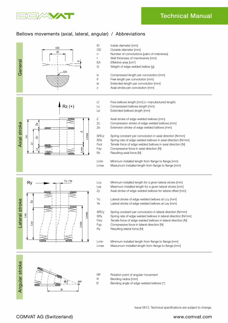
Bellows movements (axial, lateral, angular) / Abbreviations
ID Inside diameter [mm]OD Outside diameter [mm]n Number of convolutions [pairs of mebranes]t Wall thickness of membranes [mm]EA Effektive area [cm2]G Weight of edge welded bellow [g]
Ic Compressed length per convolution [mm]If Free length per convolution [mm]le Extended length per convolution [mm]z Axial stroke per convolution [mm]
Lf Free bellows length [mm] (= manufactured length)Lc Compressed bellows length [mm]Le Extended bellows length [mm]
Z Axial stroke of edge welded bellows [mm]Zc Compression stroke of edge welded bellows [mm]Ze Extension stroke of edge welded bellows [mm]
SRCz Spring constant per convolution in axial direction [N/mm]SRz Spring rate of edge welded bellows in axial direction [N/mm]Fsrz Tensile force of edge welded bellows in axial direction [N]Fzp Compressive force in axial direction [N]Rz Resulting axial force [N]
Lmin Minimum installed length from flange to flange [mm]Lmax Maxiumum installed length from flange to flange [mm]
Lcy Minimum installed length for a given lateral stroke [mm]Ley Maximum installed length for a given lateral stroke [mm]Zy Axial stroke of edge welded bellows for lateral offset [mm]
Yc Lateral stroke of edge welded bellows at Lcy [mm]Ye Lateral stroke of edge welded bellows at Ley [mm]
SRCy Spring constant per convolution in lateral direction [N/mm]SRy Spring rate of edge welded bellows in lateral direction [N/mm]Fsry Tensile force of edge welded bellows in lateral direction [N]Fyp Compressive force in lateral direction [N]Ry Resulting lateral force [N]
Lmin Minimum installed length from flange to flange [mm]Lmax Maxiumum installed length from flange to flange [mm]
RP Rotation point of angular movementR Bending radius [mm]Φ Bending angle of edge welded bellows [°]
Late
ral s
tro
keA
ngul
ar s
tro
keA
xial
str
oke
Gen
eral
Technical Manual
COMVAT AG (Switzerland)

www.comvat.com
RP= RotationspunktR= Radius (Technisches Handbuch)Y= LateralversatzL-RP= Distanz vom Endstück zum RP
Mitte Endstück
In Balgradius Mitte des Balges
Ausserhalb des Balges
Φ
R
RP
Φ
R
L-RPL-RP
RP
Φ
RY
L-RP
RP Φ
L-RP
L-RP
L-RP
R
Y
RP
RP= RotationspunktR= Radius (Technisches Handbuch)Y= LateralversatzL-RP= Distanz vom Endstück zum RP
Mitte Endstück
In Balgradius Mitte des Balges
Ausserhalb des Balges
Φ
R
RP
Φ
R
L-RPL-RP
RP
Φ
RY
L-RP
RP Φ
L-RP
L-RP
L-RP
R
Y
RP
Issue 0613. Technical specifications are subject to change.
Construction of the bellows: rotations points Angular
Technical Manual
COMVAT AG (Switzerland)
In bellows radius (standard acc. to data sheet)
Middle of end piece
RP: Rotations pointR: Radius (Technical Manual)Y: Lateral movementL-RP: Displacement from end piece to rotations point RP
Middle of the bellows
Outside of the bellows

www.comvat.com
*
b
D
OD
D-O
D
2
*
15 < 2D-OD b 3>_
60 2D-OD b 7>_>
15 < 2
D-OD b 5>_ 60
>_ >_
Issue 0613. Technical specifications are subject to change.
Premachining of the end piece N-15000
Technical Manual
COMVAT AG (Switzerland)
Minimum lip distance Customer end piece
Customer end pieceWelded bellows
Welded bellows
* Premachining the end pieces according to drawing with 0.5+0.2mm overmeasure.0

www.comvat.com
DNID
[mm]OD
[mm]ID
[Inch]OD
[Inch]Di
[mm]Da
[mm] S [mm]L CF [mm]
L ISO-K [mm]
A CF [mm]
A ISO-K [mm]
10 8 16 0.315 0.630 8,0 10,0 4,0 15,0 - 18,0 -16 16 31.5 0.630 1.240 16,0 18,0 4,0 15.8 - 20,0 -25 26 46 1.024 1.811 24,0 28,0 4,0 23.2 - 29,0 -40 39 59 1.535 2.323 38,0 41.3 4,0 23.5 34.5 29,0 40,050 51 76 2.008 2.992 53,0 57,0 4,0 28.3 34.5 34,0 40,0
DNID
[mm]OD
[mm]ID
[Inch]OD
[Inch]Di
[mm]Da
[mm] S [mm]L CF [mm]
L ISO-K [mm]
A CF [mm]
A ISO-K [mm]
63 65 90 2.559 3.543 66.0 70.0 5.0 26.5 33.0 36.0 40.075 75 100 2.953 3.937 72.1 76.1 5.0 26.5 33.0 36.0 40.0100 102 132 4.016 5.197 104.0 108.0 5.0 30.0 33.0 41.0 40.0130 127 157 5.000 6.181 123.0 129.0 5.0 30.5 37.0 42.0 44.0160 150 185 5.906 7.283 150.0 156.0 5.0 31.0 37.0 43.0 44.0200 200 235 7.874 9.252 200.0 206.0 6.0 38.0 37.0 50.5 44.0250 250 285 9.843 11.22 250.0 256.0 6.0 38.5 37.0 51.0 44.0300 300 340 11.811 13.386 300.0 306.0 6.0 42.3 44.0 55.0 54.0350 360 440 14.173 17.323 350.0 356.0 10.0 47.3 - 60.0 -400 400 480 15.748 18.898 400.0 406.0 10.0 44.0 48.0 60.0 58.0500 520 640 20.472 25.197 500.0 506.0 15.0 - 52.0 - 62.0630 690 810 27.165 31.89 650.0 662.0 15.0 - 55.5 - 68.0
Issue 0613. Technical specifications are subject to change.
End piece, one-part
End piece, two-part
Other end piece lengths, pipe diameters and materials available on request. Two-part end pieces are also available as one-part end pieces.
*) All linear measures refer to the COMVAT-"A-Dimension".
Standard material one-piece: 316LStandard material two-piece: 316L (bellows connection), 304 (pipe)
Standard End Pieces
COMVAT AG (Switzerland)

www.comvat.com
10* 25.4 1" 9.0 18.0 6.0 3.016 34.0 1 1/3" 16.0 27.0 7.5 4.225 54.0 2 1/8" 24.0 41.3 12.0 4.840 69.5 2 3/4" 38.0 58.7 13.0 5.550 85.6 3 3/8" 47.6 72.4 15.7 5.763 113.5 4 1/2" 66.0 92.2 17.5 9.575 117.5 4 5/8" 72.1 76.4 17.5 9.5100 152.0 6" 104.0 130.3 20.0 11.0130 171.4 6 3/4" 123.0 129.0 21.0 11.5160 202.5 8" 150.0 181.0 22.0 12.0200 253.0 10" 200.0 231.8 24.5 12.5250 305.0 12" 250.0 284.0 24.5 12.5300 355.6 14 1/2" 300.0 325.4 28.5 12.7350 419.1 16 1/2" 350.0 388.9 28.5 12.7400 457.0 18" 400.0 431.8 28.5 16.0
Issue 0613. Technical specifications are subject to change.
CF flange, fixed
*Flange DN10 is only available as fixed flange.Standard material: 304L / on request 316LN also available
All CF flanges can be delivered both with threaded bolt holes and as blind flange.
.
CF flange, rotating
Standard CF Flanges
COMVAT AG (Switzerland)
DN
ØB Flange
[mm]
ØB Flange
[inch]Di
[mm]Da
[mm]G
[mm]k
[mm]

www.comvat.com
DNd4
[mm]d3
[mm]Di
[mm]OD
[mm]S
[mm]
f3 +0.2/0
[mm]L
[mm]10 30.0 12.2 10.0 20.0 4.0 2.5 14.016 30.0 17.2 16.0 31.5 4.0 2.5 14.020 40.0 22.2 20.0 41.0 4.0 2.5 14.025 40.0 26.2 25.0 46.0 4.0 2.5 14.032 55.0 34.2 31.0 51.0 4.0 2.5 15.040 55.0 41.2 39.0 59.0 4.0 2.5 15.050 75.0 52.4 50.0 76.0 4.0 2.5 18.5
DNØD
[mm]Di
[mm]Da
[mm]k
[mm]b2
[mm]d7
[mm]f3
[mm]40 65.0 38.0 41.3 5.5 10.0 41.2 2.550 75.0 53.0 57.0 5.5 10.0 52.2 2.563 95.0 66.0 70.0 7.0 10.0 70.0 4.580 110.0 72.1 76.1 7.0 10.0 83.0 4.5100 130.0 104.0 108.0 7.0 10.0 102.0 4.5125 155.0 123.0 129.0 7.0 10.0 127.0 4.5160 180.0 150.0 156.0 7.0 10.0 153.0 4.5200 240.0 200.0 206.0 7.0 10.0 213.0 4.5250 290.0 250.0 256.0 7.0 10.0 261.0 4.5320 370.0 300.0 306.0 10.0 15.0 318.0 4.5400 450.0 400.0 406.0 10.0 15.0 400.0 4.5500 550.0 500.0 506.0 10.0 15.0 501.0 4.5630 690.0 600.0 608.0 12.0 20.0 651.0 4.5
Issue 0613. Technical specifications are subject to change.
ISO-KF flange (DIN 28403)
ISO-K flange (DIN 28404)
DIN 28403 / Standard material: 316LOther lengths available on request
DIN 28404 / Standard material: 304Membrane bellow mounting with one-part or two-part end piece.
Standard ISO Flanges
COMVAT AG (Switzerland)

www.comvat.com
Notes
COMVAT AG (Switzerland)

Contact us.
COMVAT AGScharastrasse 1CH-9469 Haag / Switzerland
Phone +41 81 771 60 62Fax +41 81 771 10 49Mail [email protected]
More information can be found on www.comvat.com