Embed Size (px)
Citation preview

COMSOL
V E R S I O N 3 . 2
C AD Imp o r t M o d u l e U s e r ’ s G u i d e
™

How to contact COMSOL:
BeneluxCOMSOL BV Röntgenlaan 19 2719 DX Zoetermeer The Netherlands Phone: +31 (0) 79 363 4230 Fax: +31 (0) 79 361 [email protected] www.femlab.nl
Denmark COMSOL A/S Diplomvej 376 2800 Kgs. Lyngby Phone: +45 88 70 82 00 Fax: +45 88 70 80 90 [email protected] www.comsol.dk
Finland COMSOL OY Lauttasaarentie 52 FIN-00200 Helsinki Phone: +358 9 2510 400 Fax: +358 9 2510 4010 [email protected] www.comsol.fi
France COMSOL France 19 rue des bergers F-38000 Grenoble Phone: +33 (0)4 76 46 49 01 Fax: +33 (0)4 76 46 07 42 [email protected] www.comsol.fr
Germany FEMLAB GmbHBerliner Str. 4 D-37073 Göttingen Phone: +49-551-99721-0Fax: +49-551-99721-29 [email protected]
Norway COMSOL AS Verftsgata 4 NO-7485 Trondheim Phone: +47 73 84 24 00 Fax: +47 73 84 24 01 [email protected] www.comsol.no Sweden COMSOL AB Tegnérgatan 23 SE-111 40 Stockholm Phone: +46 8 412 95 00 Fax: +46 8 412 95 10 [email protected] www.comsol.se
SwitzerlandFEMLAB GmbH Technoparkstrasse 1 CH-8005 Zürich Phone: +41 (0)44 445 2140 Fax: +41 (0)44 445 2141 [email protected] www.femlab.ch
United Kingdom COMSOL Ltd. Studio G8 Shepherds Building Rockley RoadLondon W14 0DA Phone:+44-(0)-20 7348 9000Fax: +44-(0)-20 7348 9020 [email protected] www.uk.comsol.com
United States COMSOL, Inc. 1 New England Executive Park Suite 350 Burlington, MA 01803 Phone: +1-781-273-3322 Fax: +1-781-273-6603 COMSOL, Inc. 1100 Glendon Avenue, 17th Floor Los Angeles, CA 90024 Phone: +1-310-689-7250 Fax: +1-310-689-7527
COMSOL, Inc. 744 Cowper Street Palo Alto, CA 94301 Tel: +1-650-324-9935 Fax: +1-650-324-9936
For a complete list of international representatives, visit www.comsol.com/contact
Company home pagewww.comsol.com
COMSOL user forumswww.comsol.com/support/forums
CAD Import Module User’s Guide© COPYRIGHT 1994–2005 by COMSOL AB. All rights reserved
Patent pending
The software described in this document is furnished under a license agreement. The software may be used or copied only under the terms of the license agreement. No part of this manual may be photocopied or reproduced in any form without prior written consent from COMSOL AB. Portions of this software are owned by UGS Corp. © 1986–2004. All Rights Reserved. Portions of this software are owned by Spatial Corp. © 1989–2004. All Rights Reserved.
COMSOL, COMSOL Multiphysics, and COMSOL Script are trademarks of COMSOL AB. Parasolid is a registered trademark of UGS Corp. ACIS and SAT are registered trademarks of Spatial Corp. Other product or brand names are trademarks or registered trademarks of their respective holders.
Version: September 2005 COMSOL 3.2

C O N T E N T S
C h a p t e r 1 : I n t r o d u c t i o n
Overview of the CAD Import Module 3
CAD Systems, Geometry Kernels, and File Formats . . . . . . . . . 3
File Formats Supported by COMSOL Products . . . . . . . . . . . 4
Quick Start 6
C h a p t e r 2 : U s i n g t h e C A D I m p o r t M o d u l e
Importing a Part from a File 8
Example of Importing a Part from a File . . . . . . . . . . . . . . 8
CAD Import Options . . . . . . . . . . . . . . . . . . . . . 9
Importing an Assembly from a File 10
Example of Importing an Assembly from a File . . . . . . . . . . . . 11
SolidWorks Live Connection 13
Example of Using the SolidWorks Live Connection . . . . . . . . . . 14
C O N T E N T S | i

ii | C O N T E N T S
C h a p t e r 3 : C o m m a n d R e f e r e n c e
Summary of Commands 18
Commands Grouped by Function 19
C h a p t e r 4 : G l o s s a r yGlossary of Terms . . . . . . . . . . . . . . . . . . . . . . 25
INDEX 27

1
I n t r o d u c t i o n
Welcome to the CAD Import Module. This optional package extends the COMSOL Multiphysics™ modeling environment with the ability to import 3D CAD models. Instead of drawing a geometric model with the CAD tools built into COMSOL Multiphysics, an alternative is to create it with a specialized CAD system and save it to a file—one that the CAD Import Module can open and translate it to a COMSOL Multiphysics geometry object. Then you continue the usual modeling procedure of meshing and simulating.
The CAD Import Module supports the most common 3D CAD file formats: Parasolid®, SAT®, IGES, and STEP. Moreover, it provides the possibility to set up a live connection with SolidWorks®, one of the most popular CAD systems. With this connection, you can transfer geometric models directly from SolidWorks to COMSOL Multiphysics and modify them further during the modeling process.
CATIA® V4, CATIA® V5, Autodesk Inventor®, Pro/ENGINEER®, and VDA-FS are additional widely used CAD formats. COMSOL offers a separate module for each of them as an add-on to the CAD Import Module.
This documentation covers the CAD Import Module as well as all the add-ons. For an overview of the different products and the file formats they support, see Table 1-1 on page 4.
1

2 | C H A P T E R
This chapter provides an overview and some background on the different file formats. Furthermore, you can find recommendations on which file formats to use for importing CAD models. The chapter concludes on page 6 with some “quick start” information to using the CAD Import Module. Detailed descriptions on how to use various features of this module in an optimal way appear in Chapter 2, “Using the CAD Import Module.”
1 : I N T R O D U C T I O N

Ove r v i ew o f t h e CAD Impo r t Modu l e
To get an overview of the module, first review some general background information about CAD file formats; then you can better understand the list of all file formats that various COMSOL products support. This section also includes some recommendations on which format to use together with a specific CAD system. For more details on the live connection with SolidWorks, see the section “SolidWorks Live Connection” on page 13.
CAD Systems, Geometry Kernels, and File Formats
Each CAD system uses a geometry kernel to create a mathematical description of the objects and to calculate the results of solid-modeling operations. Parasolid and ACIS® are the two most common kernels, and many CAD systems license these kernels. In addition, some systems use their own kernel (as does COMSOL Multiphysics). Each of these kernels has a native file format associated with it. For example, Parasolid’s file format is simply called Parasolid, and the one from ACIS is called SAT.
The geometry kernel defines the type of internal representations used for 3D modeling, which can vary considerably among different kernels. Hence, the representations stored in the various file formats are also very different. The CAD Import Module can read all these different descriptions of objects and translate them into COMSOL Multiphysics geometries.
In addition to the file formats that are native to a geometry kernel, yet other formats are based on neutral standards that were defined to ease the exchange of geometric models among CAD systems. STEP and IGES are the two most popular formats of this class.
Yet another class of files use surface-mesh geometry formats. They do not represent a model’s exact 3D geometry but store only triangular meshes of the surfaces. The most common examples of these types of files formats are VRML and STL.
For 2D modeling two formats are used primarily: DXF® is the native format of the 2D modeling software AutoCAD®, whereas GDS is a neutral standard.
This discussion presents only a short overview of CAD terms. The large number of systems and formats can be rather confusing. See the Glossary on page 25 for a short description of each individual CAD system, kernel, and file format.
O V E R V I E W O F T H E C A D I M P O R T M O D U L E | 3

4 | C H A P T E R
File Formats Supported by COMSOL Products
The various COMSOL products can import different sets of file formats. COMSOL Multiphysics itself comes with support for 2D formats and the surface-mesh geometry formats. The CAD Import Module covers the most common needs for translating 3D models; it reads the native formats of the two most common kernels and the most popular standards. For files from other CAD systems, we supply additional modules as add-ons to the CAD Import Module. See Table 1-1 for a summary and details on supported versions.
Geometric models do not always pass flawlessly between different file formats due to the different representations they use. This implies that the quality of a translation from a CAD model to a COMSOL Multiphysics geometry depends heavily on the file format you are using. The smoothest way is, of course, to use the native format of your CAD system. If this is not possible, we in general recommend you use STEP or Parasolid. Table 1-2 lists the preferred choices of formats for the most common CAD
TABLE 1-1: FILE FORMATS SUPPORTED BY COMSOL PRODUCTS
PRODUCT FILE FORMAT (FILE EXTENSIONS) SUPPORTED VERSIONS
COMSOL Multiphysics STL (.stl)
VRML (.wrl, .vrml)
DXF (.dxf)
GDS (.gds)
1.0
up to R14
2
CAD Import Module Parasolid (.x_t, .x_b)
SAT (.sat, .sab)
STEP (.step, .stp)
IGES (.igs, .iges)
up to V16
up to r14
AP203, AP214
up to 5.3
CATIA V4 Import Module CATIA V4 (.model) 4.1.9 to 4.2.4
CATIA V5 Import Module CATIA V5 (.CATPart, .CATProduct) R2 to R14
Inventor Import Module Autodesk Inventor (.ipt) 6 to 9
Pro/E Import Module Pro/ENGINEER (.prt, .asm) 16 to Wildfire2
VDA-FS Import Module VDA-FS (.vda) up to 2.0
1 : I N T R O D U C T I O N

systems. Note that these are general recommendations, and other formats might work better in individual cases.
TABLE 1-2: RECOMMENDATIONS FOR FILE FORMATS TO USE FOR CAD IMPORT
CAD SYSTEM NATIVE FILE FORMAT FURTHER RECOMMENDATIONS
SolidWorks, Solid Edge®, NX™ Parasolid STEP, SAT
CATIA V4 CATIA V4 STEP, Parasolid
CATIA V5 CATIA V5 STEP, Parasolid
Autodesk Inventor Autodesk Inventor SAT, STEP
Pro/ENGINEER Pro/ENGINEER STEP, Parasolid
others native format STEP, Parasolid
O V E R V I E W O F T H E C A D I M P O R T M O D U L E | 5

6 | C H A P T E R
Qu i c k S t a r t
Importing CAD files into the COMSOL Multiphysics modeling environment is straightforward. Go to the File menu and open the Import CAD Data From File dialog box, where you:
1 Select the type of file you want to import in the Files of type list.
2 Choose the file to import by clicking on it or specifying its name in the File name edit field.
3 Click Import to close the dialog box and import the geometry in the file. This action also opens the Import CAD Data From File progress window.
See Chapter 2, “Using the CAD Import Module,” for import options and more details on how to handle various types of geometries. There you also find information on the SolidWorks live connection.
1 : I N T R O D U C T I O N

2
U s i n g t h e C A D I m p o r t M o d u l e
This chapter provides more details on how to effectively use the CAD Import Module for different types of CAD models. Usually, such a CAD model is represented by either a part or an assembly. A part represents a single object, which the CAD Import Module translates to a COMSOL Multiphysics geometry. An assembly, however, is a collection of objects1. This software offers several ways for you to deal with imported assemblies.
This chapter discusses these two cases separately: See page 8 for details on how to import a part, and see page 10 for a presentation of the different ways to treat an assembly. Finally, page 13 describes the live connection to SolidWorks.
This chapter also shows how to use the CAD Import Module from the COMSOL Multiphysics graphical user interface. For details on how to access all this functionality from COMSOL Script™ or MATLAB®, see Chapter 3, “Command Reference,” on page 17.
1. Some CAD systems have the concept of multibody parts. The CAD Import Module treats them the same as assemblies.
7

8 | C H A P T E R
Impo r t i n g a Pa r t f r om a F i l e
When importing a model that is represented as a “part” in a CAD file, the CAD Import Module translates this model into a COMSOL Multiphysics geometry object. This object behaves exactly like those you create directly in COMSOL Multiphysics. This means that you can continue the modeling process with meshing and analysis in the usual fashion.
Example of Importing a Part from a File
1 Open the Model Navigator and start a new 3D model.
2 Select the menu item File>Import>CAD Data From File.
3 In the Files of type list select STEP file.
4 Locate the COMSOL32 installation directory, go to the cad folder, then select the file demo2.stp.
5 Click Import to close the dialog box and import the geometry. This action also opens the Import CAD Data From File progress window.
6 Click the Headlight button on the Camera toolbar to get a better 3D impression of the geometry.
2 : U S I N G T H E C A D I M P O R T M O D U L E
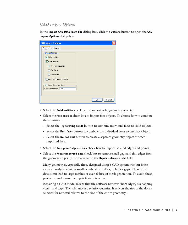
CAD Import Options
In the Import CAD Data From File dialog box, click the Options button to open the CAD
Import Options dialog box.
• Select the Solid entities check box to import solid geometry objects.
• Select the Face entities check box to import face objects. To choose how to combine these entities:
- Select the Try forming solids button to combine individual faces to solid objects.
- Select the Knit faces button to combine the individual faces to one face object.
- Select the Do not knit button to create a separate geometry object for each imported face.
• Select the Free point/edge entities check box to import isolated edges and points.
• Select the Repair imported data check box to remove small gaps and tiny edges from the geometry. Specify the tolerance in the Repair tolerance edit field.
Many geometries, especially those designed using a CAD system without finite element analysis, contain small details: short edges, holes, or gaps. These small details can lead to large meshes or even failure of mesh generation. To avoid these problems, make sure the repair feature is active.
Repairing a CAD model means that the software removes short edges, overlapping edges, and gaps. The tolerance is a relative quantity. It reflects the size of the details selected for removal relative to the size of the entire geometry.
I M P O R T I N G A P A R T F R O M A F I L E | 9

10 | C H A P T E R
Impo r t i n g an A s s emb l y f r om a F i l e
A CAD model represented as an “assembly” is a collection of objects. When importing such a model, each object becomes a COMSOL Multiphysics geometry object.
With several geometry objects present, there are three ways to continue the modeling process:
• Move each geometry object to a separate geometry tab and use coupling variables to link the objects.
This is clearly the best option and is illustrated in the section “Example of Importing an Assembly from a File” on page 11.
• Keep the objects in the same geometry. When you leave Draw mode, the software combines them into one object. You achieve the same result by clicking the Union button on the Draw toolbar.
This option does not always work because when combining the objects the software can encounter problems (usually resolving the subdomains). Even if combining the objects is successful, this approach restricts modeling freedom because you cannot mesh each object individually.
• Combine the assembly to one object (a “part”) while still working in your CAD system. Then import the resulting part, which the CAD Import Module translates into one COMSOL Multiphysics geometry object.
Use this option with caution because it could change the object significantly depending on the CAD system. Often this method deletes internal boundaries, and thus it takes areas you might want to model as individual subdomains and combines them into one. You also loose the freedom to create a mesh for each object separately.
The CAD import options are exactly the same whether importing assemblies or parts. See the section “CAD Import Options” on page 9 for details.
2 : U S I N G T H E C A D I M P O R T M O D U L E

Example of Importing an Assembly from a File
1 Open the Model Navigator and start a new 3D model.
2 Select the menu item File>Import>CAD Data From File.
3 In the Files of type list choose Parasolid file.
4 Locate the COMSOL32 installation directory, go to the cad directory, then select the file demo3.x_t.
5 Click Import to close the dialog box and import the geometry. This action also opens the Import CAD Data From File progress window.
6 Click the Headlight button on the Camera toolbar to get a better 3D impression of the geometry.
With this example file you get three objects in the same geometry. Move them each to an individual geometry by following these steps:
1 From the Multiphysics menu select Model Navigator.
2 Click the Add Geometry button, and in the resulting dialog box click OK.
3 Repeat Step 2 to create a third geometry.
4 Click OK in the Model Navigator dialog box.
5 Now you have created three geometries. View the original one by selecting the Geom1 tab.
6 Select the rightmost geometry object by clicking on it.
I M P O R T I N G A N A S S E M B L Y F R O M A F I L E | 11

12 | C H A P T E R
7 From the Edit menu select Cut.
8 Select the Geom3 tab.
9 From the Edit menu select Paste, then click OK in the Paste dialog box.
10 Return to the original geometry by selecting the Geom1 tab.
11 From the two remaining geometry objects, select the one to the right by clicking on it.
12 From the Edit menu select Cut.
13 Select the Geom2 tab.
14 From the Edit menu select Paste, then click OK in the Paste dialog box.
15 Return to the original geometry by selecting the Geom1 tab.
16 To visualize the two objects you have moved to Geom2 and Geom3, select the menu item Options>View Geometries.
17 Select both Geom2 and Geom3, then click OK.
Now the model has three geometries with one geometry object in each of them. You are ready to set up coupling variables with identity boundary conditions. For a detailed description on how to do so and continue the modeling process, go to the COMSOL Multiphysics User’s Guide and read the section “Multigeometry Linking” on page 240.
2 : U S I N G T H E C A D I M P O R T M O D U L E

S o l i dWo rk s L i v e C onn e c t i o n
With the CAD Import Module you can set up a live connection between COMSOL Multiphysics and the SolidWorks CAD system. In this way, the modeling environment mirrors the SolidWorks model as a COMSOL Multiphysics geometry. The connection is truly bidirectional. On the one hand, you can modify a model in SolidWorks and simultaneously update the COMSOL Multiphysics geometry. On the other hand, you can define constants in COMSOL Multiphysics, which SolidWorks can use as geometric parameters.
A typical design and modeling process includes some or all of the following steps:
1 Create a CAD model in SolidWorks.
2 Initialize the connection from COMSOL Multiphysics.
3 Perform initial modeling studies.
4 Modify the CAD model in SolidWorks.
5 Update the geometry in COMSOL Multiphysics from the new CAD model. The program maps the boundary conditions from the old model to the new one. Note that this step is based on common-sense heuristics and might give undesired results in some cases.
6 Continue modeling in COMSOL Multiphysics.
7 Define constants that serve as parameters to the geometric model.
8 Update the connection between the two programs. SolidWorks reads the defined constants and changes the CAD model accordingly, and the connection updates the COMSOL Multiphysics object.
9 Perform a parameter study by changing the values of the constants and updating the connection repeatedly.
Note that a geometry object, which mirrors a CAD model in SolidWorks, should not be manipulated in COMSOL Multiphysics. However, you can draw additional objects in COMSOL Multiphysics. This means that your model can contain both geometry objects imported from SolidWorks and geometry objects drawn in COMSOL Multiphysics.
The live connection transfers only the geometry from SolidWorks to COMSOL Multiphysics; it ignores everything else. Furthermore, the connection requires that both programs are running on the same PC.
S O L I D W O R K S L I V E C O N N E C T I O N | 13

14 | C H A P T E R
To specify options on how to translate a SolidWorks model to a COMSOL Multiphysics geometry object, select the menu item File>SolidWorks
Connection>Options. The options are exactly the same as for importing CAD models from files and are discussed in the section “CAD Import Options” on page 9.
Example of Using the SolidWorks Live Connection
Start the program SolidWorks on your computer. Locate the COMSOL32 installation directory, go to the cad folder, then open the file demo4.SLDPRT.
Set up the live connection to COMSOL Multiphysics using the following steps:
1 Open the Model Navigator and start a new 3D model.
2 From the File menu select SolidWorks Connection>Initialize.
3 A progress window opens, and the connection translates the SolidWorks model to a COMSOL Multiphysics geometry.
Now modify the SolidWorks model, which is mirrored in the COMSOL Multiphysics geometry.
2 : U S I N G T H E C A D I M P O R T M O D U L E

1 In the Feature tree on the left side of the SolidWorks window, locate the symbol called Equations. The constant fillet_radius is presently set to 5. This value determines the size of the fillet that is slightly darker than the rest of the drawing.
2 Select Edit Equation by right-clicking on the text fillet_radius.
3 Change the value to 1, and the fillet in the model becomes very small.
4 Return to the COMSOL Multiphysics window. Select the menu item File>SolidWorks Connection>Update to adjust the geometry to the changes you just made in SolidWorks.
As another exercise, assume that this radius is too small for your modeling needs, but you want to control its size from within COMSOL Multiphysics. This is possible and illustrates the bidirectional nature of the connection.
1 In COMSOL Multiphysics select the menu item Options>Constants.
S O L I D W O R K S L I V E C O N N E C T I O N | 15

16 | C H A P T E R
2 Define a constant with the name fillet_radius and in the corresponding Expression edit field enter 4, then click OK.
3 Select the menu item File>SolidWorks Connection>Update.
4 This action updates the fillet in the COMSOL Multiphysics geometry to the new value. In addition, the connection updates the value of fillet_radius and the drawing in SolidWorks.
2 : U S I N G T H E C A D I M P O R T M O D U L E

3
C o m m a n d R e f e r e n c e
17

18 | C H A P T E R
S umma r y o f C ommand sgeomimport on page 20
geomupdate on page 22
swbody on page 23
swinit on page 24
3 : C O M M A N D R E F E R E N C E

Command s G r oup ed b y Fun c t i o n
Geometry Functions
Geometry Objects
FUNCTION PURPOSE
geomimport Import geometry objects from file
geomupdate Update geometry data in FEM structure
swinit Initialize connection with SolidWorks
FUNCTION PURPOSE
swbody SolidWorks imported body
C O M M A N D S G R O U P E D B Y F U N C T I O N | 19

geomimport
20 | C H A P T E
geomimportPurpose Import geometry objects from a file.
Syntax gl = geomimport(filename,...)
Description gl = geomimport(filename,...) reads the geometry file filename and translates the geometry data using the specified properties into a cell array of geometries gl.
filename can be any of the following formats:
Note 1: This format requires a license for the COMSOL CAD Import Module.
Note 2: This format requires a license for a format-specific module from COMSOL.
This command supports the following properties:
TABLE 3-1: SUPPORTED FILE FORMATS
FILE FORMAT NOTE FILE EXTENSIONS
Autodesk Inventor 2 .ipt
CATIA V4 2 .model
CATIA V5 2 .CATPart, .CATProduct
COMSOL Multiphysics Binary .mphbin
COMSOL Multiphysics Text .mphtxt
DXF .dxf
GDS .gds
IGES 1 .igs, .iges
Parasolid 1 .x_t, .x_b
Pro/ENGINEER 2 .prt, .asm
SAT 1 .sat, .sab
STEP 1 .step, .stp
STL .stl
VDA-FS 2 .vda
VRML .wrl, .vrml
TABLE 3-2: VALID PROPERTY/VALUE PAIRS
PROPERTY NAME PROPERTY VALUE
DEFAULT DESCRIPTION
Coercion solid | face | off
solid Coerce the imported geometry
Keepbnd on | off on Keep boundary entities
R 3 : C O M M A N D R E F E R E N C E

geomimport
When importing COMSOL Multiphysics files and those in the GDS format, the command ignores these properties.
For DXF import, the default for Coercion is curve.
For STL and VRML imports, the command supports all properties in meshenrich (see the entry on meshenrich in the COMSOL Multiphysics Command Reference).
Coercion can force the import process to knit boundary segments together and possibly try to form solid entities.
Keepbnd, Keepfree, and Keepsolid indicate which type of entities the module should consider in the imported data.
Repair determines if the module should process the imported data to improve the quality. These operations include the snapping of points, removal of small entities, and improvement of geometric data.
Repairtol is a relative tolerance. It indicates the size of entities to remove, which points to snap together, and similar features.
Report determines if a progress window should appear during the call.
Examples filepath = which('demo1.dxf');% Importing the DXF file demo1.dxf as a curve2 object.g = geomimport(filepath);geomplot(g{1})
Diagnostics geomimport replaces the functionality of the COMSOL Multiphysics 3.0 functions dxfread, igesread, stlread, and vrmlread. We no longer support those functions and their properties and thus do not document them.
See Also geom0, geom1, geom2, geom3, meshimport, geomexport
Keepfree on | off off Keep free edge/point entities
Keepsolid on | off on Keep solid entities
Repair on | off on Repair imported data
Repairtol positive scalar
1e-4 Repair tolerance
Report on | off on Display a progress window
TABLE 3-2: VALID PROPERTY/VALUE PAIRS
PROPERTY NAME PROPERTY VALUE
DEFAULT DESCRIPTION
21
geomupdate
22 | C H A P T E
geomupdatePurpose Update geometry data contained in an FEM structure.
Syntax fem = geomupdate(fem,...)
Description fem = geomupdate(fem,...) updates geometry objects contained in the FEM structure fem.
If fem contains geometry objects of type swbody and there is an existing SolidWorks connection, the SolidWorks geometry is updated according to variables the geomupdate command passes, and these bodies are synchronized with SolidWorks.
Use geomanalyze to update the rest of the FEM structure after updating the geometry objects.
This command supports the following properties:
This command supports all properties of geomimport.
See Also geomanalyze, geomimport
TABLE 3-3: VALID PROPERTY/VALUE PAIRS
PROPERTY NAME PROPERTY VALUE
DEFAULT DESCRIPTION
Const cell array Definition of constants
Geomnum integer 1 Number of the FEM structure in an extended FEM structure
R 3 : C O M M A N D R E F E R E N C E

swbody
swbodyPurpose Create a SolidWorks synchronized geometry object.
Syntax s3 = swbody
Description s3 = swbody creates a SolidWorks synchronized geometry object.
A swbody is a geom3 object that is generated from a SolidWorks connection and that can be updated from SolidWorks by calling geomupdate.
If there is no active SolidWorks connection, the swbody object acts as an ordinary geom3 object.
See Also geom0, geom1, geom2, geom3, geomupdate
23

swinit
24 | C H A P T E
swinitPurpose Initialize a connection with SolidWorks.
Syntax gl = swinit(doc,...)
Description gl = swinit(doc,...) returns a cell array of SolidWorks bodies obtained from the part document doc. If doc is an empty string, the current document is used.
See Also geomanalyze, geomupdate
R 3 : C O M M A N D R E F E R E N C E

4
G l o s s a r y
This glossary contains CAD-specific terms that describe file formats and software packages in a general context. For geometric terms specific to COMSOL Multiphysics, see the glossary in the COMSOL Multiphysics User’s Guide. To find references that point to more information about a term, see the index.
Glossary of Terms
ACIS A geometry kernel from Spatial Corp. with SAT as its native file format.
AutoCAD A 2D CAD system from Autodesk, Inc.
Autodesk Inventor Name of both a CAD system and its native file format (.ipt). from Autodesk, Inc. The kernel of this CAD system is based on ACIS.
CAD Computer-aided design.
CATIA V4 Name of both a CAD system and its native file format (.model) from Dassault Systèmes S.A. It is fundamentally different to CATIA V5.
25

26 | C H A P T E R
CATIA V5 Name of both a CAD system and its native file format (.CATPart, .CATProduct) from Dassault Systèmes S.A. It is fundamentally different to CATIA V4.
DXF The 2D file format (.dxf) native to AutoCAD from Autodesk, Inc.
GDS A 2D file format (.gds) based on a neutral standard.
IGES A file format (.igs, .iges) based on a neutral standard not native to any geometry kernel.
NX A CAD system (formerly known as Unigraphics) from UGS Corp. using the Parasolid kernel.
Parasolid Name of both a geometry kernel and its native file format (.x_t, .x_b) from UGS Corp.
Pro/ENGINEER Name of both a CAD system and its native file format (.prt, .asm) from Parametric Technology Corp.
SAT The native file format (.sat, .sab) of the ACIS geometry kernel from Spatial Corp.
Solid Edge A CAD system from UGS Corp. using the Parasolid kernel.
SolidWorks A CAD system from SolidWorks Corp. using the Parasolid kernel.
STEP A file format (.step, .stp) based on a neutral standard not native to any geometry kernel.
STL A file format (.stl) based on a neutral standard using surface-mesh representations.
VDA-FS A file format (.vda) based on a neutral standard not native to any geometry kernel.
VRML A file format (.wrl, .vrml) based on a neutral standard using surface mesh representations.
4 : G L O S S A R Y

I N D E X
A ACIS 3
assembly
example 11
importing 10
Autodesk Inventor 4, 5
C CAD files
formats 4
importing 6
CAD software 5
CAD systems 5
CATIA V4 4, 5
CATIA V5 4, 5
coupling variables 10
D DXF 4
E example
assembly 11
importing 6
part 8
SolidWorks 14
F file extensions 4
file formats 3
Autodesk Inventor 4
CATIA V4 4
CATIA V5 4
DXF 3
GDS 3
IGES 3
Parasolid 3
Pro/ENGINEER 4
SAT 3
STEP 3
STL 3
VDA-FS 4
VRML 3
G GDS 4
geometry kernels 3
ACIS 3
Parasolid 3
I IGES 4
importing
assembly 10
CAD files 6
options 9
part 8
L live connection 13
N NX 5
O options 9
P parameter study 13
Parasolid 4
part
example 8
importing 8
Pro/ENGINEER 4, 5
Q quick start 6
R repairing 9
S SAT 4
Solid Edge 5
SolidWorks 5, 13
example 14
live connection 13
STEP 4
STL 4
T tolerance
repairing 9
V VDA-FS 4
VRML 4
I N D E X | 27

28 | I N D E X